WO2021090391A1 - 空気調和装置の室外機、及び、空気調和装置の室外機の組み立て方法 - Google Patents
空気調和装置の室外機、及び、空気調和装置の室外機の組み立て方法 Download PDFInfo
- Publication number
- WO2021090391A1 WO2021090391A1 PCT/JP2019/043429 JP2019043429W WO2021090391A1 WO 2021090391 A1 WO2021090391 A1 WO 2021090391A1 JP 2019043429 W JP2019043429 W JP 2019043429W WO 2021090391 A1 WO2021090391 A1 WO 2021090391A1
- Authority
- WO
- WIPO (PCT)
- Prior art keywords
- oil separator
- outdoor unit
- air conditioner
- partition plate
- bed
- Prior art date
Links
Images


Classifications
-
- F—MECHANICAL ENGINEERING; LIGHTING; HEATING; WEAPONS; BLASTING
- F24—HEATING; RANGES; VENTILATING
- F24F—AIR-CONDITIONING; AIR-HUMIDIFICATION; VENTILATION; USE OF AIR CURRENTS FOR SCREENING
- F24F1/00—Room units for air-conditioning, e.g. separate or self-contained units or units receiving primary air from a central station
- F24F1/06—Separate outdoor units, e.g. outdoor unit to be linked to a separate room comprising a compressor and a heat exchanger
- F24F1/46—Component arrangements in separate outdoor units
-
- F—MECHANICAL ENGINEERING; LIGHTING; HEATING; WEAPONS; BLASTING
- F24—HEATING; RANGES; VENTILATING
- F24F—AIR-CONDITIONING; AIR-HUMIDIFICATION; VENTILATION; USE OF AIR CURRENTS FOR SCREENING
- F24F1/00—Room units for air-conditioning, e.g. separate or self-contained units or units receiving primary air from a central station
- F24F1/06—Separate outdoor units, e.g. outdoor unit to be linked to a separate room comprising a compressor and a heat exchanger
- F24F1/56—Casing or covers of separate outdoor units, e.g. fan guards
Definitions
- the present invention relates to an outdoor unit of an air conditioner having a structure for fixing an oil separator to a partition plate using auxiliary parts, and a method of assembling an outdoor unit of an air conditioner.
- the inside of the outdoor unit of the air conditioner is divided into a blower room and a machine room by a partition plate.
- the blower room is equipped with a blower and a heat exchanger, and the machine room contains electronic parts and piping assemblies. It is equipped.
- a component called an accumulator that stores refrigerant is connected to the assembly of piping in the machine room.
- an accumulator is arranged above the compressor in order to reduce the size of the machine room.
- the accumulator is fixed to the partition plate above the compressor.
- Patent Document 1 proposes that a reinforcing plate is attached to a partition plate and an accumulator is directly attached to the reinforcing plate.
- the present invention has been made to solve the above problems, and is an outdoor unit of an air conditioner capable of improving workability when attaching an oil separator to a partition plate, and an air conditioner. This is to obtain a method for assembling the outdoor unit.
- the outdoor unit of the air conditioner according to the present invention includes a blower room, a machine room, and a partition plate that separates the blower room and the machine room, and the compressor and the oil separator are housed in the machine room.
- the oil separator is fixed to the partition plate by an auxiliary part, and the auxiliary part is detachably attached to the leg portion fixed to the partition plate and the leg portion.
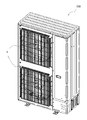
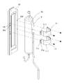
- FIG. 1 is a perspective view of the appearance of the outdoor unit 100 of the air conditioner according to the present embodiment.
- FIG. 2 is a perspective view of the inside of the outdoor unit 100 of the air conditioner according to the present embodiment.
- the outdoor unit 100 of the air conditioner has, for example, two blowers 4 provided side by side in the vertical direction.
- the inside of the outdoor unit 100 of the air conditioner is divided into a blower room 2 and a machine room 3 by a partition plate 1.
- a blower 4 and a heat exchanger 5 are arranged in the blower room 2.
- a compressor 6, an electric component box 7, and an oil separator assembly 8 are arranged.
- the oil separator assembly 8 is configured by connecting a plurality of pipes to the oil separator 8a.
- the oil separator 8a has a cylindrical shape and has a function of separating oil from the gas refrigerant discharged from the compressor 6.
- the oil separator assembly 8 is arranged above the compressor 6 and is connected to the discharge pipe 6a of the compressor 6.
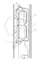
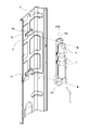
- FIG. 3 is a perspective view showing a state in which the oil separator assembly 8 according to the embodiment is attached to the partition plate 1. As shown in FIG. 3, the oil separator assembly 8 is attached to the partition plate 1 by an auxiliary part composed of a leg portion 9, a bed portion 10, and a band portion 11.
- the bed portion 10 is fixed to the leg portion 9 fixed to the partition plate 1, and the oil separator assembly 8 is supported by the bed portion 10, so that the partition plate 1 is formed. It is attached. Further, the oil separator assembly 8 is fixed to the bed portion 10 by the band portion 11.
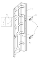
- FIG. 4 is a detailed view of the leg portion 9 according to the embodiment.
- FIG. 5 is a detailed view of the leg portion 9 according to the embodiment, and is a view of the leg portion 9 of FIG. 4 as viewed from the opposite side.
- the leg portion 9 includes a flat surface portion 91 located at both ends in the longitudinal direction of the leg portion 9, a central portion 92 located between the two flat surface portions 91, and a flat surface portion 91. It is composed of a connecting portion 93 that connects to the central portion 92.
- the connecting portion 93 extends in a direction intersecting the flat surface portion 91 and the central portion 92, and connects the flat surface portion 91 extending in parallel with each other and the central portion 92 in a stepped shape.
- a total of three alignment holes 9a are formed in the flat surfaces 91 at both ends.
- the alignment hole 9a is provided to align the leg portion 9 with the mounting position of the partition plate 1.
- one alignment hole 9a is formed in one of the flat surface portions 91 at both ends, and two are formed in the other flat surface portion 91.
- the two alignment holes 9a formed in the other flat surface portion 91 are formed, for example, in different dimensions from each other.
- the three alignment holes 9a provided in the flat surfaces 91 at both ends clarify the vertical and horizontal directions of the legs 9 and facilitate keeping the height positions of the flat portions 91 at both ends horizontal.
- the central portion 92 and the connecting portion 93 of the leg portion 9 have a leg flange 9b formed by bending the upper edge and the lower edge.
- the rigidity of the leg portion 9 can be increased by forming the leg flange 9b extending in the direction intersecting the flat plate surfaces of the central portion 92 and the connecting portion 93.
- a screw hole 9c is formed in the central portion 92 of the leg portion 9.
- the screw hole 9c is a hole into which a screw for fixing the bed portion 10 is inserted into the leg portion 9.
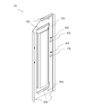
- FIG. 6 is a detailed view of the bed portion 10 according to the embodiment.
- FIG. 7 is a detailed view of the bed portion 10 according to the embodiment, and is a view of the bed portion 10 of FIG. 6 as viewed from the opposite side.
- the bed portion 10 has a recessed portion 10a formed in the center.
- a flat plate surface is provided on the outer periphery of the recessed portion 10a.
- the flat plate-shaped region on the outer circumference of the recessed portion 10a is referred to as the outer peripheral portion 101.
- a screw hole 10e is provided on the outer peripheral portion 101 of the bed portion 10 in the lateral direction.
- the bed portion 10 is detachably attached to the leg portion 9 with the outer peripheral portion 101 of the flat surface in contact with the central portion 92 of the leg portion 9 by a screw inserted into the screw hole 10e of the bed portion 10.
- the bed portion 10 has a bed portion flange 10b extending from the edge of the outer peripheral portion 101 in a direction intersecting with the outer peripheral portion 101.
- the bed flange 10b is formed by bending the edge of the outer peripheral portion 101, for example.
- the bed portion flange 10b is formed of, for example, a member provided so as to protrude from the bed portion 10.
- the bed portion flange 10b of the bed portion 10 is provided to hook the bed portion 10 to the leg portion flange 9b of the leg portion 9 when the bed portion 10 is attached to the leg portion 9. Therefore, the bed flange 10b has a shape that follows the shape of the leg flange 9b of the leg 9.
- the recessed portion 10a of the bed portion 10 has a contour having a shape extending along the longitudinal direction of the bed portion 10, and is recessed in the same direction as the extending direction of the bed portion flange 10b.
- the oil separator 8a of the oil separator assembly 8 is fitted in the recessed portion 10a, whereby the oil separator assembly 8 is supported by the bed portion 10.
- a cushioning material 10d is attached to the inner surface of the recessed portion 10a.
- the cushioning material 10d for example, a sponge or the like can be used.
- a screw hole 10f and a quadrangular square hole 10c are formed in the outer peripheral portion 101 of the bed portion 10 along the longitudinal direction of the bed portion 10.
- the square hole 10c of the bed portion 10 is formed to align the band portion 11 with the mounting position.
- the screw hole 10f of the bed portion 10 is formed to fix the band portion 11 to the bed portion 10.
- FIG. 8 is a detailed view of the band portion 11 according to the embodiment.
- FIG. 9 is a detailed view of the band portion 11 according to the embodiment, and is a view of the band portion 11 of FIG. 8 as viewed from the opposite side.
- the band portion 11 is composed of a curved surface portion 111 at the center and flat surface portions 112 on both sides of the curved surface portion 111.
- the curved surface portion 111 has a curved surface shape along the outer peripheral surface of the oil separator 8a.
- a cushioning material 11b is attached to the inside of the curved surface portion 111. Since the curved surface portion 111 of the band portion 11 serves as a contact surface with the oil separator 8a, the gap between the band portion 11 and the oil separator 8a can be reduced by providing the cushioning material 11b. As a result, the oil separator 8a is strongly pressed against the band portion 11, so that the transmission of vibration is suppressed and abnormal noise is reduced.
- a claw portion 11a projecting downward from the lower end is formed on one of the flat surface portions 112 on both sides of the curved surface portion 111.
- the claw portion 11a is inserted into the square hole 10c of the bed portion 10, and the band portion 11 and the bed portion 10 are aligned with each other.
- Screw holes 11c are formed in each of the flat surface portions 112 on both sides of the curved surface portion 111.
- the screw hole 11c of the band portion 11 is screwed to the screw hole 10e of the bed portion 10, and the band portion 11 is fixed to the bed portion 10.
- FIG. 10 is a perspective view showing a step of fixing the leg portion 9 according to the embodiment to the partition plate 1.
- the leg portion 9 in the step of fixing the leg portion 9 to the partition plate 1, the leg portion 9 is arranged so that the longitudinal direction of the leg portion 9 is along the width direction of the partition plate 1.
- the partition plate 1 and the leg portion 9 are aligned so that the alignment hole 9a of the leg portion 9 is fitted into the embossed portion 1a formed on the partition plate 1.
- the flat surface portions 91 are fixed to the partition plate 1 by spot welding in a state where the flat surface portions 91 at both ends of the leg portion 9 are in contact with the partition plate 1.
- the leg portion 9 is fixed to the partition plate 1.
- the embossed portion 1a has a shape in which a part of the partition plate 1 projects from the blower chamber 2 toward the machine chamber 3.
- the embossed portion 1a is formed by, for example, embossing.
- the legs 9 are attached to the partition plate 1 at two locations in the vertical direction.
- the legs 9 may be provided at two or more locations in the vertical direction of the partition plate 1. It is preferable that the number of legs 9 is two or more because the load is dispersed and the load applied to one leg 9 is suppressed. Further, since the leg portion 9 is formed with three alignment holes 9a, the mounting positions of the partition plate 1 in the vertical direction and the horizontal direction become more accurate.
- FIG. 11 is a perspective view showing a step of fixing the oil separator assembly 8, the bed portion 10, and the band portion 11 according to the embodiment.
- the oil separator 8a is placed on the recessed portion 10a of the bed portion 10.
- the oil separator assembly 8 is fixed to the bed portion 10 by the band portion 11. Specifically, the curved surface portion 111 of the band portion 11 is aligned with the outer peripheral surface of the oil separator 8a, and the flat surface portion 112 of the band portion 11 is aligned with the outer peripheral portion 101 of the bed portion 10. Then, the claw portion 11a of the band portion 11 is inserted into the square hole 10c of the bed portion 10 to position the band portion 11, and the band portion 112 is in contact with the outer peripheral portion 101 of the bed portion 10 and the flat portion 112 of the band portion 11. The screw hole 11c of the portion 11 and the screw hole 10e of the bed portion 10 are screwed together.
- the oil separator assembly 8 is fixed to the bed portion 10 by the band portion 11. Similar to the leg portion 9, the band portion 11 is attached at two locations in the vertical direction of the oil separator 8a, but the band portion 11 may be provided at two or more locations in the vertical direction of the oil separator 8a. It is preferable that the number of band portions 11 is two or more because the oil separator 8a is more firmly fixed.
- FIG. 12 is a perspective view showing a process of attaching the oil separator assembly 8 according to the embodiment to the partition plate 1.
- the bed portion flange 10b of the bed portion 10 to which the oil separator assembly 8 is fixed by the band portion 11 is fixed to the partition plate 1.
- Hook on the leg flange 9b of the leg 9 is fixed to the partition plate 1.
- the piping of the oil separator assembly 8 and the discharge piping 6a of the compressor 6 are connected to complete the assembly of the outdoor unit 100 of the air conditioner.
- the oil separator assembly 8 is mounted on the legs 9 fixed to the partition plate 1 and the oil separator assembly 8. It is fixed to the partition plate 1 by an auxiliary part having a bed portion 10. Therefore, even if the weight of the oil separator assembly 8 increases, the partition plate 1 can be reinforced by the auxiliary member to ensure the rigidity of the partition plate 1. Further, since the leg portion 9 of the auxiliary part fixed to the partition plate 1 and the bed portion 10 on which the oil separator assembly 8 is placed can be attached and detached, the work of attaching the oil separator assembly 8 to the partition plate 1 becomes easier.
- the oil separator assembly 8 is fixed to the partition plate 1, it is not necessary for the operator to support the oil separator assembly 8 when connecting the compressor 6 to the oil separator assembly 8, and the connection work is easy. It becomes. Further, since the leg portion 9 and the bed portion 10 which are auxiliary parts are interposed between the oil separator assembly 8 and the partition plate 1, the oil separator assembly 8 is directly fixed to the partition plate 1. It is possible to suppress the vibration transmitted to the partition plate 1 as compared with the above. As a result, the vibration of the pipe during the operation of the outdoor unit 100 is transmitted to the oil separator assembly 8, and the vibration of the pipe connected to the oil separator assembly 8 is suppressed.
- the oil separator assembly 8 is integrated with the bed portion 10 by the band portion 11, the work of attaching the oil separator assembly 8 to the partition plate 1 becomes easy.
- the alignment between the leg portion 9 and the partition plate 1 becomes easy.
- the rigidity of the leg portion 9 and the bed portion 10 can be increased by the leg flange 9b of the leg portion 9 and the bed portion flange 10b of the bed portion 10.
- the leg portion 9 and the bed portion 10 can be easily aligned and fixed.
- leg portion 9 in the state where the oil separator assembly 8 is not attached is easy to handle, it is easy to attach it to the partition plate 1.
- the leg portion 9 and the partition plate 1 are securely fixed.
- the bed portion 10 is fixed to the leg portion 9 with a screw, the work of attaching the oil separator assembly 8 to the partition plate 1 becomes easy.
- the gap between the bed portion 10 and the oil separator assembly 8 can be reduced, so that the bed portion 10 and the oil separator assembly 8 are less likely to be displaced due to vibration or the like. , Noise can also be reduced.
- the cushioning material 11b in the band portion 11 the gap between the band portion 11 and the oil separator assembly 8 can be reduced, so that noise can be reduced.
- the oil separator 8a is fitted into the recessed portion 10a of the bed portion 10, the posture of the oil separator 8a placed on the bed portion 10 is stable.
Landscapes
- Engineering & Computer Science (AREA)
- Chemical & Material Sciences (AREA)
- Combustion & Propulsion (AREA)
- Mechanical Engineering (AREA)
- General Engineering & Computer Science (AREA)
- Other Air-Conditioning Systems (AREA)
- Applications Or Details Of Rotary Compressors (AREA)
Abstract
補助部品を用いてオイルセパレータを仕切り板に固定する構造を備えた空気調和装置の室外機、及び、空気調和装置の室外機の組み立て方法。空気調和装置の室外機は、送風機室と、機械室と、送風機室と機械室とを仕切る仕切り板と、を備え、機械室に圧縮機及びオイルセパレータが収容された空気調和装置の室外機において、オイルセパレータは、補助部品により仕切り板に固定されており、補助部品は、仕切り板に固定された脚部と、脚部に着脱可能に取り付けられ、オイルセパレータを支持しているベッド部と、を備えている。
Description
本発明は、補助部品を用いてオイルセパレータを仕切り板に固定する構造を備えた空気調和装置の室外機、及び、空気調和装置の室外機の組み立て方法に関する。
空気調和装置の室外機の内部は、仕切り板により送風機室と機械室とに区割りされており、送風機室には送風機及び熱交換器が備えられ、機械室には電子部品及び配管の組立品が備えられている。機械室の配管の組立品には、アキュムレータと呼ばれる冷媒を貯蔵する部品が接続されている。室外機の機種によっては、機械室を小型化するために、アキュムレータが圧縮機の上方に配置されている。このような構成の室外機として、アキュムレータを圧縮機上方で仕切り板に固定するものがある。
特許文献1では、仕切り板に補強板を宛がい、その補強板に直にアキュムレータを取り付けることが提案されている。補強板を取り付けて仕切り板の剛性を高めることで、アキュムレータの重量に耐えうる仕切り板の剛性を確保し、また、アキュムレータから仕切り板に伝わる振動を抑制している。
特許文献1にあるようなアキュムレータを仕切り板に固定するものにおいては、重量の大きいアキュムレータを補強板に固定しなければならず、他の部品を組立てる際の作業性に難がある。オイルセパレータとオイルセパレータに接続される配管とから構成されるオイルセパレータ組立品についてもアキュムレータと同様である。すなわち、仕切り板の剛性を確保するため、特許文献1のように、補強板を介してオイルセパレータ組立品を仕切り板に取り付けようとした場合にも、オイルセパレータ組立品を仕切り板に固定された補強板に固定しなければない。そのため、作業性が悪くなるという問題が生じる。
本発明は、上記のような課題を解決するためになされたものであり、オイルセパレータを仕切り板に取り付ける際の作業性を改善することができる空気調和装置の室外機、及び、空気調和装置の室外機の組み立て方法を得るものである。
本発明に係る空気調和装置の室外機は、送風機室と、機械室と、前記送風機室と前記機械室とを仕切る仕切り板と、を備え、前記機械室に圧縮機及びオイルセパレータが収容された空気調和装置の室外機において、前記オイルセパレータは、補助部品により前記仕切り板に固定されており、前記補助部品は、前記仕切り板に固定された脚部と、前記脚部に着脱可能に取り付けられ、前記オイルセパレータを支持しているベッド部と、を備えている。
本発明に係る空気調和装置の室外機によれば、オイルセパレータを仕切り板に取り付ける際の作業性を向上させることができる。
図1は、本実施の形態に係る空気調和装置の室外機100の外観の斜視図である。また、図2は、本実施の形態に係る空気調和装置の室外機100の内部の斜視図である。図1に示すように、空気調和装置の室外機100は、例えば、上下方向に並べて設けた2つの送風機4を有している。図2に示すように、空気調和装置の室外機100の内部は、仕切り板1により、送風機室2と、機械室3とに区割りされている。送風機室2には、送風機4と、熱交換器5とが配置されている。機械室3には、圧縮機6と、電気品箱7と、オイルセパレータ組立品8とが配置されている。
オイルセパレータ組立品8は、オイルセパレータ8aに複数の配管が接続されて構成されている。オイルセパレータ8aは、円筒形状を有し、圧縮機6から吐出されたガス冷媒から油分を分離させる機能を有する。オイルセパレータ組立品8は、圧縮機6の上方に配置されており、圧縮機6の吐出配管6aと接続されている。
図3は、実施の形態に係るオイルセパレータ組立品8が仕切り板1に取り付けられた状態を示す斜視図である。図3に示すように、オイルセパレータ組立品8は、脚部9と、ベッド部10と、バンド部11とにより構成された補助部品により仕切り板1に取り付けられている。
具体的には、オイルセパレータ組立品8は、仕切り板1に固定された脚部9にベッド部10が固定され、ベッド部10にオイルセパレータ組立品8が支持されることで、仕切り板1に取り付けられている。また、オイルセパレータ組立品8は、バンド部11によりベッド部10に固定されている。
図4は、実施の形態に係る脚部9の詳細図である。図5は、実施の形態に係る脚部9の詳細図であって、図4の脚部9を反対側から見た図である。図4及び図5に示すように、脚部9は、脚部9の長手方向の両端に位置する平面部91と、2つの平面部91の間に位置する中央部92と、平面部91と中央部92とを接続する接続部93とにより構成されている。接続部93は、平面部91及び中央部92に交差する方向に延びており、互いに平行に延びる平面部91と中央部92とを段差状に接続している。
両端の平面部91には、合計3つの位置合わせ穴9aが形成されている。位置合わせ穴9aは、脚部9を仕切り板1の取付位置に位置合わせするために設けられている。位置合わせ穴9aは、例えば、両端の平面部91のうちの一方の平面部91に1つ、他方の平面部91に2つ形成されている。また、他方の平面部91に形成された2つの位置合わせ穴9aは、例えば、互いに異なる寸法に形成されている。両端の平面部91に設けられた3つの位置合わせ穴9aは、脚部9の上下方向及び左右方向を明確にし、両端の平面部91の高さ位置を水平に保つことを容易にしている。
脚部9の中央部92及び接続部93は、上縁及び下縁が折り曲げられて形成された脚部フランジ9bを有する。中央部92及び接続部93の平板面に対して交差する方向に延びる脚部フランジ9bが形成されていることで、脚部9の剛性を高めることができる。
脚部9の中央部92には、ネジ穴9cが形成されている。ネジ穴9cは、脚部9にベッド部10を固定するためのネジが挿入される穴である。
図6は、実施の形態に係るベッド部10の詳細図である。図7は、実施の形態に係るベッド部10の詳細図であって、図6のベッド部10を反対側から見た図である。図6及び図7に示すように、ベッド部10は、中央に形成された窪み部10aを有する。窪み部10aの外周は、平板面が設けられている。窪み部10aの外周の平板状の領域を外周部101と称する。
ベッド部10の短手方向における外周部101には、ネジ穴10eが設けられている。ベッド部10は、ベッド部10のネジ穴10eに挿通されるネジにより、平面の外周部101が脚部9の中央部92に接した状態で脚部9に着脱可能に取り付けられる。
ベッド部10は、外周部101の縁から外周部101と交差する方向に延びるベッド部フランジ10bを有する。ベッド部フランジ10bは、例えば、外周部101の縁部を折り曲げて形成されている。また、ベッド部フランジ10bは、例えば、ベッド部10から突出するように設けられた部材により形成されている。ベッド部10のベッド部フランジ10bは、ベッド部10を脚部9に取り付ける際に脚部9の脚部フランジ9bに引っかけるために設けられている。従って、ベッド部フランジ10bは、脚部9の脚部フランジ9bの形状に沿った形状を有する。ベッド部10にベッド部フランジ10bを設けることで、ベッド部10を脚部9に取り付ける作業が容易になる。
ベッド部10の窪み部10aは、ベッド部10の長手方向に沿って延びた形状の輪郭を有し、ベッド部フランジ10bが延びる方向と同じ方向に窪んでいる。窪み部10aには、オイルセパレータ組立品8のオイルセパレータ8aがはめ込まれ、これによりオイルセパレータ組立品8がベッド部10に支持される。
窪み部10aの内面には、緩衝材10dが貼り付けられている。緩衝材10dとして、例えば、スポンジなどを用いることができる。ベッド部10とオイルセパレータ8aとの接触面となる窪み部10aに緩衝材10dを設けることで、ベッド部10とオイルセパレータ8aとの隙間を縮小できる。これにより、振動によるオイルセパレータ組立品8とベッド部10とのズレなどが生じにくくなる。
ベッド部10の外周部101には、ネジ穴10fと、四角形の角穴10cとがベッド部10の長手方向に沿って形成されている。ベッド部10の角穴10cは、バンド部11を取付位置に位置合わせするために形成されている。ベッド部10のネジ穴10fは、ベッド部10にバンド部11を固定するために形成されている。
図8は、実施の形態に係るバンド部11の詳細図である。図9は、実施の形態に係るバンド部11の詳細図であって、図8のバンド部11を反対側から見た図である。図8及び図9に示すように、バンド部11は、中央の曲面部111と、曲面部111の両側の平面部112とにより構成されている。
曲面部111は、オイルセパレータ8aの外周面に沿った曲面形状になっている。曲面部111の内側には、緩衝材11bが貼り付けられている。バンド部11の曲面部111は、オイルセパレータ8aとの接触面となるため、緩衝材11bが設けられていることでバンド部11とオイルセパレータ8aとの隙間を縮小できる。これにより、オイルセパレータ8aがバンド部11に強く押さえつけられるため、振動の伝達が抑制されて異音が低減される。
曲面部111の両側の平面部112のうちの一方には、下端から下方に突出する爪部11aが形成されている。爪部11aがベッド部10の角穴10cに挿入されて、バンド部11とベッド部10とが位置合わせされる。
曲面部111の両側の平面部112のそれぞれには、ネジ穴11cが形成されている。
バンド部11のネジ穴11cが、ベッド部10のネジ穴10eとネジ止めされて、バンド部11がベッド部10に固定される。
バンド部11のネジ穴11cが、ベッド部10のネジ穴10eとネジ止めされて、バンド部11がベッド部10に固定される。
続いて、本実施の形態に係る空気調和装置の室外機100の組み立て方法について説明する。
図10は、実施の形態に係る脚部9を仕切り板1に固定する工程を示す斜視図である。図10に示すように、脚部9を仕切り板1に固定する工程では、脚部9の長手方向が仕切り板1の幅方向に沿うように脚部9を配置する。そして、脚部9の位置合わせ穴9aを、仕切り板1に形成されたエンボス部1aに嵌めるように、仕切り板1と脚部9とを位置合わせする。そして、脚部9の両端の平面部91が仕切り板1に接した状態で、スポット溶接により平面部91を仕切り板1に固定する。これにより、脚部9が仕切り板1に固定される。
エンボス部1aは、仕切り板1の一部が送風機室2から機械室3に向けて突出する形状である。エンボス部1aは、例えば、型押しなどにより形成されている。脚部9は、仕切り板1の上下方向の2箇所に取り付けられている。脚部9は、仕切り板1の上下方向の2箇所以上に設けてもよい。脚部9の数を2個以上とすることで荷重が分散され、1つの脚部9にかかる荷重が抑制されるため好ましい。また、脚部9に位置合わせ穴9aが3つ形成されていることで、仕切り板1の上下方向及び左右方向の取付位置がより正確になる。
図11は、実施の形態に係るオイルセパレータ組立品8とベッド部10とバンド部11とを固定する工程を示す斜視図である。オイルセパレータ組立品8とベッド部10とバンド部11とを固定する工程では、まず、オイルセパレータ8aをベッド部10の窪み部10aにあてがい載置する。
次に、バンド部11によりオイルセパレータ組立品8をベッド部10に固定する。具体的には、バンド部11の曲面部111をオイルセパレータ8aの外周面に沿わせ、バンド部11の平面部112をベッド部10の外周部101に沿わせる。そして、バンド部11の爪部11aをベッド部10の角穴10cに挿入してバンド部11を位置決めし、ベッド部10の外周部101にバンド部11の平面部112が接した状態で、バンド部11のネジ穴11cとベッド部10のネジ穴10eとをネジ止めする。
これにより、オイルセパレータ組立品8がバンド部11によりベッド部10に固定される。なお、バンド部11は、脚部9と同様、オイルセパレータ8aの上下方向の2箇所取り付けられているが、オイルセパレータ8aの上下方向の2箇所以上に設けてもよい。バンド部11の数を2個以上とすることでオイルセパレータ8aがより強固に固定されるため好ましい。
図12は、実施の形態に係るオイルセパレータ組立品8を仕切り板1に取り付ける工程を示す斜視図である。図12に示すように、オイルセパレータ組立品8を仕切り板1に取り付ける工程では、バンド部11によりオイルセパレータ組立品8が固定されたベッド部10のベッド部フランジ10bを、仕切り板1に固定された脚部9の脚部フランジ9bに引っかける。そして、ベッド部10のネジ穴10eと、脚部9のネジ穴9cとをネジにより固定することで、オイルセパレータ組立品8が仕切り板1に取り付けられる。
オイルセパレータ組立品8を仕切り板1に取り付けた後、オイルセパレータ組立品8の配管と、圧縮機6の吐出配管6aとを接続し、空気調和装置の室外機100の組み立てが完了する。
以上説明した、本実施の形態に係る空気調和装置の室外機100によれば、オイルセパレータ組立品8を、仕切り板1に固定された脚部9と、オイルセパレータ組立品8が載置されるベッド部10とを有する補助部品により、仕切り板1に固定している。そのため、オイルセパレータ組立品8の重量が増加しても、仕切り板1が補助部材により補強されて仕切り板1の剛性を確保することができる。また、仕切り板1に固定された補助部品の脚部9と、オイルセパレータ組立品8が載置されたベッド部10とが着脱可能であるため、オイルセパレータ組立品8を仕切り板1に取り付ける作業が容易になる。また、オイルセパレータ組立品8が仕切り板1に固定されることで、オイルセパレータ組立品8に圧縮機6を接続する際にオイルセパレータ組立品8を作業者が支える必要がなくなり、接続作業が容易となる。また、オイルセパレータ組立品8と仕切り板1との間に補助部品である脚部9及びベッド部10が介在する構成であるため、オイルセパレータ組立品8が直で仕切り板1に固定された場合に比べ、仕切り板1に伝達する振動を抑制することができる。これにより、室外機100の運転時における配管の振動がオイルセパレータ組立品8に伝達し、オイルセパレータ組立品8に接続された配管が振動することが抑制される。
また、バンド部11によりオイルセパレータ組立品8がベッド部10と一体となるため、オイルセパレータ組立品8を仕切り板1に取り付ける作業が容易となる。
また、仕切り板1にエンボス部1aを設けることで、脚部9と仕切り板1との位置合わせが容易となる。
また、脚部9の脚部フランジ9b及びベッド部10のベッド部フランジ10bにより、脚部9及びベッド部10の剛性を高めることができる。また、脚部9とベッド部10との位置合わせ及び固定が容易となる。
また、オイルセパレータ組立品8が取り付けられていない状態の脚部9は、取り扱いが容易であるため、仕切り板1に取り付けることが容易である。脚部9と仕切り板1とをスポット溶接により固定することで、脚部9と仕切り板1との固定が確実となる。一方、ベッド部10は、脚部9にネジにより固定されるため、オイルセパレータ組立品8の仕切り板1への取付作業が容易となる。
また、ベッド部10に緩衝材10dを設けることで、ベッド部10とオイルセパレータ組立品8との隙間を縮小できるため、振動などによるベッド部10とオイルセパレータ組立品8とのズレが発生しにくく、騒音を低減することもできる。同様に、バンド部11に緩衝材11bを設けることで、バンド部11とオイルセパレータ組立品8との隙間を縮小できるため、騒音を低減することができる。
また、オイルセパレータ8aは、ベッド部10の窪み部10aにはめ込まれるため、ベッド部10に載置されたオイルセパレータ8aの姿勢が安定する。
1 仕切り板、1a エンボス部、2 送風機室、3 機械室、4 送風機、5 熱交換器、6 圧縮機、6a 吐出配管、7 電気品箱、8 オイルセパレータ組立品、8a オイルセパレータ、9 脚部、9a 位置合わせ穴、9b 脚部フランジ、9c ネジ穴、10 ベッド部、10a 窪み部、10b ベッド部フランジ、10c 角穴、10d 緩衝材、10e ネジ穴、10f ネジ穴、11 バンド部、11a 爪部、11b 緩衝材、11c ネジ穴、91 平面部、92 中央部、93 接続部、100 室外機、101 外周、111 曲面部、112 平面部。
Claims (10)
- 送風機室と、機械室と、前記送風機室と前記機械室とを仕切る仕切り板と、を備え、
前記機械室に圧縮機及びオイルセパレータが収容された空気調和装置の室外機において、
前記オイルセパレータは、補助部品により前記仕切り板に固定されており、
前記補助部品は、
前記仕切り板に固定された脚部と、
前記脚部に着脱可能に取り付けられ、前記オイルセパレータを支持しているベッド部と、を備えている
空気調和装置の室外機。 - 前記補助部品は、
前記ベッド部に前記オイルセパレータを固定しているバンド部を更に備えた
請求項1に記載の空気調和装置の室外機。 - 前記ベッド部と、前記バンド部とは、ネジにより固定されている
請求項2に記載の空気調和装置の室外機。 - 前記脚部は、位置合わせ穴を有し、
前記仕切り板は、エンボス部を有し、
前記エンボス部が前記位置合わせ穴に嵌め合わされている
請求項1~3の何れか一項に記載の空気調和装置の室外機。 - 前記脚部には、脚部フランジが形成されており、
前記ベッド部には、ベッド部フランジが形成されており、
前記脚部と、前記ベッド部とは、前記脚部フランジに前記ベッド部フランジが引っかけられて固定されている
請求項1~4の何れか一項に記載の空気調和装置の室外機。 - 前記脚部は、前記仕切り板に、スポット溶接により固定されており、
前記脚部と、前記ベッド部とは、ネジにより固定されている
請求項1~5の何れか一項に記載の空気調和装置の室外機。 - 前記補助部品と、前記オイルセパレータとの接触面に、緩衝材が設けられている
請求項1~6の何れか一項に記載の空気調和装置の室外機。 - 前記ベッド部は、上下方向に延びる窪みを有する
請求項1~7の何れか一項に記載の空気調和装置の室外機。 - 送風機室と機械室とを仕切る仕切り板の前記機械室側に、補助部品の脚部を固定する工程と、
前記脚部に、オイルセパレータが載置された前記補助部品のベッド部を固定する工程と、
前記オイルセパレータに、前記機械室に収容された圧縮機の吐出配管を接続する工程と、
を有する空気調和装置の室外機の組み立て方法。 - 前記脚部に、前記オイルセパレータが載置された前記補助部品の前記ベッド部を固定する工程の前に、
前記ベッド部に前記オイルセパレータを載置する工程と、
前記ベッド部に載置した前記オイルセパレータを、前記補助部品のバンド部により、前記ベッド部に固定する工程と、
を有する請求項9に記載の空気調和装置の室外機の組み立て方法。
Priority Applications (5)
| Application Number | Priority Date | Filing Date | Title |
|---|---|---|---|
| CN201980101432.2A CN114599920A (zh) | 2019-11-06 | 2019-11-06 | 空调装置的室外机以及空调装置的室外机的组装方法 |
| JP2021554459A JPWO2021090391A1 (ja) | 2019-11-06 | 2019-11-06 | |
| DE112019007872.0T DE112019007872T5 (de) | 2019-11-06 | 2019-11-06 | Außeneinheit für eine Klimaanlage und Verfahren zum Zusammenbauen einer Außeneinheit für eine Klimaanlage |
| PCT/JP2019/043429 WO2021090391A1 (ja) | 2019-11-06 | 2019-11-06 | 空気調和装置の室外機、及び、空気調和装置の室外機の組み立て方法 |
| US17/637,215 US20220299214A1 (en) | 2019-11-06 | 2019-11-06 | Outdoor unit for air-conditioning apparatus and method for assembling outdoor unit for air-conditioning apparatus |
Applications Claiming Priority (1)
| Application Number | Priority Date | Filing Date | Title |
|---|---|---|---|
| PCT/JP2019/043429 WO2021090391A1 (ja) | 2019-11-06 | 2019-11-06 | 空気調和装置の室外機、及び、空気調和装置の室外機の組み立て方法 |
Publications (1)
| Publication Number | Publication Date |
|---|---|
| WO2021090391A1 true WO2021090391A1 (ja) | 2021-05-14 |
Family
ID=75848829
Family Applications (1)
| Application Number | Title | Priority Date | Filing Date |
|---|---|---|---|
| PCT/JP2019/043429 WO2021090391A1 (ja) | 2019-11-06 | 2019-11-06 | 空気調和装置の室外機、及び、空気調和装置の室外機の組み立て方法 |
Country Status (5)
| Country | Link |
|---|---|
| US (1) | US20220299214A1 (ja) |
| JP (1) | JPWO2021090391A1 (ja) |
| CN (1) | CN114599920A (ja) |
| DE (1) | DE112019007872T5 (ja) |
| WO (1) | WO2021090391A1 (ja) |
Citations (6)
| Publication number | Priority date | Publication date | Assignee | Title |
|---|---|---|---|---|
| JP2004270919A (ja) * | 2002-09-23 | 2004-09-30 | Tecumseh Products Co | コンプレッサの取付けブラケットと製造方法 |
| JP2008267651A (ja) * | 2007-04-18 | 2008-11-06 | Matsushita Electric Ind Co Ltd | 組立式換気扇 |
| JP2013194960A (ja) * | 2012-03-16 | 2013-09-30 | Daikin Industries Ltd | 冷凍装置の室外機 |
| CN207865564U (zh) * | 2017-12-08 | 2018-09-14 | 大金工业株式会社 | 一种空调室外机 |
| CN208846576U (zh) * | 2018-08-23 | 2019-05-10 | 宁波奥克斯电气股份有限公司 | 减震抱攀及空调机 |
| JP2019163878A (ja) * | 2018-03-19 | 2019-09-26 | 株式会社富士通ゼネラル | 空気調和機の室外機 |
Family Cites Families (6)
| Publication number | Priority date | Publication date | Assignee | Title |
|---|---|---|---|---|
| KR100995432B1 (ko) * | 2007-09-25 | 2010-11-18 | 산요덴키가부시키가이샤 | 공기 조화 장치의 실외 유닛 |
| JP4859801B2 (ja) | 2007-09-28 | 2012-01-25 | 三洋電機株式会社 | 空気調和装置の室外ユニット |
| CN202547029U (zh) * | 2012-04-16 | 2012-11-21 | 珠海格力电器股份有限公司 | 用于油分离器的固定装置 |
| CN104197430B (zh) * | 2014-09-17 | 2017-03-15 | 珠海格力电器股份有限公司 | 空调室外机 |
| JP6732110B2 (ja) * | 2017-04-18 | 2020-07-29 | 三菱電機株式会社 | 室外機、空気調和機、及び、室外機の製造方法 |
| CN108826514B (zh) * | 2018-08-23 | 2023-08-11 | 宁波奥克斯电气股份有限公司 | 一体式固定支架、油分气分固定组件及空调器 |
-
2019
- 2019-11-06 CN CN201980101432.2A patent/CN114599920A/zh active Pending
- 2019-11-06 JP JP2021554459A patent/JPWO2021090391A1/ja active Pending
- 2019-11-06 DE DE112019007872.0T patent/DE112019007872T5/de active Pending
- 2019-11-06 WO PCT/JP2019/043429 patent/WO2021090391A1/ja active Application Filing
- 2019-11-06 US US17/637,215 patent/US20220299214A1/en active Pending
Patent Citations (6)
| Publication number | Priority date | Publication date | Assignee | Title |
|---|---|---|---|---|
| JP2004270919A (ja) * | 2002-09-23 | 2004-09-30 | Tecumseh Products Co | コンプレッサの取付けブラケットと製造方法 |
| JP2008267651A (ja) * | 2007-04-18 | 2008-11-06 | Matsushita Electric Ind Co Ltd | 組立式換気扇 |
| JP2013194960A (ja) * | 2012-03-16 | 2013-09-30 | Daikin Industries Ltd | 冷凍装置の室外機 |
| CN207865564U (zh) * | 2017-12-08 | 2018-09-14 | 大金工业株式会社 | 一种空调室外机 |
| JP2019163878A (ja) * | 2018-03-19 | 2019-09-26 | 株式会社富士通ゼネラル | 空気調和機の室外機 |
| CN208846576U (zh) * | 2018-08-23 | 2019-05-10 | 宁波奥克斯电气股份有限公司 | 减震抱攀及空调机 |
Also Published As
| Publication number | Publication date |
|---|---|
| DE112019007872T5 (de) | 2022-09-01 |
| JPWO2021090391A1 (ja) | 2021-05-14 |
| CN114599920A (zh) | 2022-06-07 |
| US20220299214A1 (en) | 2022-09-22 |
Similar Documents
| Publication | Publication Date | Title |
|---|---|---|
| JP4768664B2 (ja) | 冷却機器 | |
| JP6219763B2 (ja) | 圧縮機のワッシャー固定治具および圧縮機の固定方法 | |
| WO2021090391A1 (ja) | 空気調和装置の室外機、及び、空気調和装置の室外機の組み立て方法 | |
| JP2006226644A (ja) | 空気調和機の室外機 | |
| KR101543004B1 (ko) | 차량용 배터리 마운팅 유닛 | |
| US20150000867A1 (en) | Compression apparatus and cooler unit | |
| JP5994323B2 (ja) | 空気調和機の室外機 | |
| JP2021067006A (ja) | 振れ止め装置 | |
| JP2016090166A (ja) | 冷凍装置 | |
| JP6272110B2 (ja) | 車両用空気調和装置 | |
| US7281907B2 (en) | Offset mounting foot | |
| JP2015107805A (ja) | 室外機運搬体および運搬用枠体 | |
| JP2007303789A (ja) | 空気調和機の室外機及び室外機の取付け脚の製造方法 | |
| JP4712679B2 (ja) | ヒートポンプ装置 | |
| CN216448285U (zh) | 一种空调外机的支架组件及空调器 | |
| CN213841452U (zh) | 一种车载冰箱 | |
| WO2016103447A1 (ja) | 室外機 | |
| WO2020059142A1 (ja) | 輸送用冷凍ユニット及び輸送用冷凍ユニット組立方法 | |
| JP2016138495A (ja) | 電動圧縮機の取付構造 | |
| WO2018138792A1 (ja) | 空気調和機の室外機 | |
| CN219344908U (zh) | 限位减振装置及具有其的空调器 | |
| US20230052219A1 (en) | Vibration isolator and outdoor unit for air-conditioning apparatus | |
| CN111018361B (zh) | 托架 | |
| JP6984039B2 (ja) | 空気調和機の室内機 | |
| WO2018116334A1 (ja) | 空気調和機の室外機 |
Legal Events
| Date | Code | Title | Description |
|---|---|---|---|
| 121 | Ep: the epo has been informed by wipo that ep was designated in this application |
Ref document number: 19952093 Country of ref document: EP Kind code of ref document: A1 |
|
| ENP | Entry into the national phase |
Ref document number: 2021554459 Country of ref document: JP Kind code of ref document: A |
|
| 122 | Ep: pct application non-entry in european phase |
Ref document number: 19952093 Country of ref document: EP Kind code of ref document: A1 |