WO2021085070A1 - 車両用操向装置 - Google Patents
車両用操向装置 Download PDFInfo
- Publication number
- WO2021085070A1 WO2021085070A1 PCT/JP2020/038170 JP2020038170W WO2021085070A1 WO 2021085070 A1 WO2021085070 A1 WO 2021085070A1 JP 2020038170 W JP2020038170 W JP 2020038170W WO 2021085070 A1 WO2021085070 A1 WO 2021085070A1
- Authority
- WO
- WIPO (PCT)
- Prior art keywords
- steering angle
- steering
- control unit
- ecu
- unit
- Prior art date
- Legal status (The legal status is an assumption and is not a legal conclusion. Google has not performed a legal analysis and makes no representation as to the accuracy of the status listed.)
- Ceased
Links
Images





Classifications
-
- B—PERFORMING OPERATIONS; TRANSPORTING
- B62—LAND VEHICLES FOR TRAVELLING OTHERWISE THAN ON RAILS
- B62D—MOTOR VEHICLES; TRAILERS
- B62D5/00—Power-assisted or power-driven steering
- B62D5/04—Power-assisted or power-driven steering electrical, e.g. using an electric servo-motor connected to, or forming part of, the steering gear
- B62D5/0421—Electric motor acting on or near steering gear
-
- B—PERFORMING OPERATIONS; TRANSPORTING
- B62—LAND VEHICLES FOR TRAVELLING OTHERWISE THAN ON RAILS
- B62D—MOTOR VEHICLES; TRAILERS
- B62D5/00—Power-assisted or power-driven steering
- B62D5/04—Power-assisted or power-driven steering electrical, e.g. using an electric servo-motor connected to, or forming part of, the steering gear
- B62D5/0457—Power-assisted or power-driven steering electrical, e.g. using an electric servo-motor connected to, or forming part of, the steering gear characterised by control features of the drive means as such
- B62D5/046—Controlling the motor
-
- B—PERFORMING OPERATIONS; TRANSPORTING
- B62—LAND VEHICLES FOR TRAVELLING OTHERWISE THAN ON RAILS
- B62D—MOTOR VEHICLES; TRAILERS
- B62D15/00—Steering not otherwise provided for
- B62D15/02—Steering position indicators ; Steering position determination; Steering aids
- B62D15/021—Determination of steering angle
- B62D15/0215—Determination of steering angle by measuring on the steering column
- B62D15/022—Determination of steering angle by measuring on the steering column on or near the connection between the steering wheel and steering column
-
- B—PERFORMING OPERATIONS; TRANSPORTING
- B62—LAND VEHICLES FOR TRAVELLING OTHERWISE THAN ON RAILS
- B62D—MOTOR VEHICLES; TRAILERS
- B62D15/00—Steering not otherwise provided for
- B62D15/02—Steering position indicators ; Steering position determination; Steering aids
- B62D15/021—Determination of steering angle
- B62D15/0225—Determination of steering angle by measuring on a steering gear element, e.g. on a rack bar
-
- B—PERFORMING OPERATIONS; TRANSPORTING
- B62—LAND VEHICLES FOR TRAVELLING OTHERWISE THAN ON RAILS
- B62D—MOTOR VEHICLES; TRAILERS
- B62D5/00—Power-assisted or power-driven steering
- B62D5/04—Power-assisted or power-driven steering electrical, e.g. using an electric servo-motor connected to, or forming part of, the steering gear
- B62D5/0457—Power-assisted or power-driven steering electrical, e.g. using an electric servo-motor connected to, or forming part of, the steering gear characterised by control features of the drive means as such
- B62D5/046—Controlling the motor
- B62D5/0463—Controlling the motor calculating assisting torque from the motor based on driver input
-
- B—PERFORMING OPERATIONS; TRANSPORTING
- B62—LAND VEHICLES FOR TRAVELLING OTHERWISE THAN ON RAILS
- B62D—MOTOR VEHICLES; TRAILERS
- B62D5/00—Power-assisted or power-driven steering
- B62D5/04—Power-assisted or power-driven steering electrical, e.g. using an electric servo-motor connected to, or forming part of, the steering gear
- B62D5/0457—Power-assisted or power-driven steering electrical, e.g. using an electric servo-motor connected to, or forming part of, the steering gear characterised by control features of the drive means as such
- B62D5/046—Controlling the motor
- B62D5/0466—Controlling the motor for returning the steering wheel to neutral position
-
- B—PERFORMING OPERATIONS; TRANSPORTING
- B62—LAND VEHICLES FOR TRAVELLING OTHERWISE THAN ON RAILS
- B62D—MOTOR VEHICLES; TRAILERS
- B62D5/00—Power-assisted or power-driven steering
- B62D5/04—Power-assisted or power-driven steering electrical, e.g. using an electric servo-motor connected to, or forming part of, the steering gear
- B62D5/0457—Power-assisted or power-driven steering electrical, e.g. using an electric servo-motor connected to, or forming part of, the steering gear characterised by control features of the drive means as such
- B62D5/0481—Power-assisted or power-driven steering electrical, e.g. using an electric servo-motor connected to, or forming part of, the steering gear characterised by control features of the drive means as such monitoring the steering system, e.g. failures
-
- B—PERFORMING OPERATIONS; TRANSPORTING
- B62—LAND VEHICLES FOR TRAVELLING OTHERWISE THAN ON RAILS
- B62D—MOTOR VEHICLES; TRAILERS
- B62D5/00—Power-assisted or power-driven steering
- B62D5/04—Power-assisted or power-driven steering electrical, e.g. using an electric servo-motor connected to, or forming part of, the steering gear
- B62D5/0457—Power-assisted or power-driven steering electrical, e.g. using an electric servo-motor connected to, or forming part of, the steering gear characterised by control features of the drive means as such
- B62D5/0481—Power-assisted or power-driven steering electrical, e.g. using an electric servo-motor connected to, or forming part of, the steering gear characterised by control features of the drive means as such monitoring the steering system, e.g. failures
- B62D5/0484—Power-assisted or power-driven steering electrical, e.g. using an electric servo-motor connected to, or forming part of, the steering gear characterised by control features of the drive means as such monitoring the steering system, e.g. failures for reaction to failures, e.g. limp home
-
- B—PERFORMING OPERATIONS; TRANSPORTING
- B62—LAND VEHICLES FOR TRAVELLING OTHERWISE THAN ON RAILS
- B62D—MOTOR VEHICLES; TRAILERS
- B62D5/00—Power-assisted or power-driven steering
- B62D5/04—Power-assisted or power-driven steering electrical, e.g. using an electric servo-motor connected to, or forming part of, the steering gear
- B62D5/0457—Power-assisted or power-driven steering electrical, e.g. using an electric servo-motor connected to, or forming part of, the steering gear characterised by control features of the drive means as such
- B62D5/0481—Power-assisted or power-driven steering electrical, e.g. using an electric servo-motor connected to, or forming part of, the steering gear characterised by control features of the drive means as such monitoring the steering system, e.g. failures
- B62D5/049—Power-assisted or power-driven steering electrical, e.g. using an electric servo-motor connected to, or forming part of, the steering gear characterised by control features of the drive means as such monitoring the steering system, e.g. failures detecting sensor failures
-
- B—PERFORMING OPERATIONS; TRANSPORTING
- B62—LAND VEHICLES FOR TRAVELLING OTHERWISE THAN ON RAILS
- B62D—MOTOR VEHICLES; TRAILERS
- B62D5/00—Power-assisted or power-driven steering
- B62D5/04—Power-assisted or power-driven steering electrical, e.g. using an electric servo-motor connected to, or forming part of, the steering gear
- B62D5/0457—Power-assisted or power-driven steering electrical, e.g. using an electric servo-motor connected to, or forming part of, the steering gear characterised by control features of the drive means as such
- B62D5/0481—Power-assisted or power-driven steering electrical, e.g. using an electric servo-motor connected to, or forming part of, the steering gear characterised by control features of the drive means as such monitoring the steering system, e.g. failures
- B62D5/0493—Power-assisted or power-driven steering electrical, e.g. using an electric servo-motor connected to, or forming part of, the steering gear characterised by control features of the drive means as such monitoring the steering system, e.g. failures detecting processor errors, e.g. plausibility of steering direction
Definitions
- the present invention relates to a vehicle steering device.
- a steering reaction force generator (FFA: Force Feedback Actuator, steering mechanism) in which the driver steers, and a tire steering device (RWA: Road Wheel Actuator, steering mechanism) that steers the vehicle.
- FFA Force Feedback Actuator
- RWA Road Wheel Actuator, steering mechanism
- SBW Steer By Wire
- the steering mechanism and the steering mechanism are electrically connected via a control unit (ECU: Electronic Control Unit), and an electric signal is used between the steering mechanism and the steering mechanism. Is generally controlled.
- ECU Electronic Control Unit
- an electric signal is used between the steering mechanism and the steering mechanism. Is generally controlled.
- a configuration in which the steering mechanism and the steering mechanism are controlled by different ECUs can be considered (for example, Patent Document 1).
- the present invention has been made in view of the above problems, and an object of the present invention is to provide a vehicle steering device capable of realizing a fail-safe function of a vehicle system with a simple configuration.
- Any one of the detected values of the plurality of rudder angle sensors is controlled as the steering angle of the handle, and is output to the first control unit via the communication system to control the first control.
- the unit controls the reaction force device based on the steering angle of the handle input from the second control unit via the communication system.
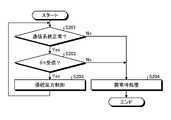
- a safe stop processing according to the automatic driving level is performed, and the driver is notified that the steering angle detection function has failed.
- a safer vehicle system fail-safe function can be realized.
- FIG. 1 is a diagram showing an overall configuration of a steering device for a steer-by-wire vehicle.
- FIG. 2 is a schematic diagram showing a hardware configuration of a control unit that controls an SBW system.
- FIG. 3 is a diagram showing an example of the internal block configuration of the control unit.
- FIG. 4 is a block diagram showing a configuration example of the twist angle control unit.
- FIG. 5 is a block diagram showing a configuration example of the target steering angle generation unit.
- FIG. 6 is a block diagram showing a configuration example of the steering angle control unit.
- FIG. 7 is a flowchart showing an operation example of the steering angle control unit.
- FIG. 8 is a diagram showing an example of a system schematic configuration of a steering device for a vehicle of a steer-by-wire type according to an embodiment.
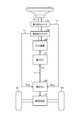
- FIG. 1 is a diagram showing the overall configuration of a steer-by-wire type vehicle steering device.
- the steer-by-wire (SBW: Steer By Wheel) type vehicle steering device (hereinafter, also referred to as “SBW system”) shown in FIG. 1 includes a reaction force device 60 and a drive device 70, and the operation of the steering wheel 1 is an electric signal. It is a system that transmits to the steering mechanism consisting of steering wheels 8L, 8R, etc.
- the control unit (ECU) 50 as a control unit controls both the reaction force device 60 and the drive device 70 is illustrated.
- the reaction force device 60 transmits the motion state of the vehicle transmitted from the steering wheels 8L and 8R to the driver as reaction force torque.
- the reaction force torque is generated by the reaction force motor 61.
- the drive device 70 includes a drive motor 71, a gear 72, and the like.
- the driving force generated by the driving motor 71 is connected to the steering wheels 8L and 8R via the gear 72, the pinion rack mechanism 5, the tie rods 6a and 6b, and further via the hub units 7a and 7b.
- ROM 1002 stores a control program for controlling the SBW system. Further, the RAM 1003 is used as a work memory for operating the control program.
- the EEPROM 1004 stores control data and the like input and output by the control program. The control data is used on the control computer program expanded in the RAM 1003 after the power is turned on to the control unit 30, and is overwritten on the EEPROM 1004 at a predetermined timing.
- ROM 1002, RAM 1003, EEPROM 1004, etc. are storage devices for storing information, and are storage devices (primary storage devices) that can be directly accessed by the CPU 1001.
- Interface 1005 is connected to CAN40.
- the interface 1005 is for receiving a vehicle speed V signal (vehicle speed pulse) from the vehicle speed sensor 12.
- the PWM controller 1007 outputs PWM control signals for each phase of UVW based on the current command values for the reaction force motor 61 and the drive motor 71.
- the target steering torque generation unit 200 generates the target steering torque Tref, which is the target value of the steering torque when the steering system of the vehicle is assisted and controlled in the present disclosure.
- the conversion unit 500 converts the target steering torque Tref into the target twist angle ⁇ ref.
- the torsion angle control unit 300 generates a motor current command value Imc, which is a control target value of the current supplied to the reaction force motor 61.
- twist angle control unit 300 will be described with reference to FIG.
- the target twist angle ⁇ ref output from the conversion unit 500 is additionally input to the subtraction unit 361.
- the twist angle ⁇ is subtracted and input to the subtraction unit 361 and input to the torsion angular velocity calculation unit 320.
- the motor angular velocity ⁇ m is input to the stabilization compensation unit 340.
- the subtraction unit 333 calculates the difference ( ⁇ ref- ⁇ t) between the target torsional velocity ⁇ ref and the torsional angular velocity ⁇ t.
- the integration unit 331 integrates the difference ( ⁇ ref ⁇ t) between the target torsional velocity ⁇ ref and the torsional angular velocity ⁇ t, and adds and inputs the integration result to the subtraction unit 334.
- the addition unit 362 adds the motor current command value Imca1 from the speed control unit 330 and the motor current command value Imca2 from the stabilization compensation unit 340, and outputs the motor current command value Imccb.
- the configuration of the twist angle control unit 300 in this embodiment is an example, and may be different from the configuration shown in FIG.
- the twist angle control unit 300 may not include the stabilization compensation unit 340.
- the target steering angle generation unit 910 In the steering angle control, the target steering angle generation unit 910 generates the target steering angle ⁇ tref based on the steering angle ⁇ h.
- the target steering angle ⁇ tref is input to the steering angle control unit 920 together with the steering angle ⁇ t, and the motor current command value Imct so that the steering angle ⁇ t becomes the target steering angle ⁇ tref in the steering angle control unit 920. Is calculated. Then, based on the motor current command value Imct and the current value Imd of the drive motor 71 detected by the motor current detector 940, the current control unit 930 has the same configuration and operation as the current control unit 130, and the drive motor has the same configuration and operation. The 71 is driven to control the current.
- the target steering angle generation unit 910 will be described with reference to FIG.
- FIG. 6 is a block diagram showing a configuration example of the steering angle control unit.
- the steering angle control unit 920 calculates the motor current command value Imct based on the target steering angle ⁇ tref and the steering angles ⁇ t of the steering wheels 8L and 8R.
- the steering angle control unit 920 includes a steering angle feedback (FB) compensation unit 921, a steering angular velocity calculation unit 922, a speed control unit 923, an output limiting unit 926, and a subtraction unit 927.
- FB steering angle feedback
- the target steering angle ⁇ tref output from the target steering angle generation unit 910 is additionally input to the subtraction unit 927.
- the steering angle ⁇ t is subtracted and input to the subtracting unit 927 and input to the steering angular velocity calculation unit 922.
- the target steering angular velocity ⁇ tref is input to the speed control unit 923.
- the steering angle FB compensation unit 921 and the speed control unit 923 make it possible to make the steering angle ⁇ t follow the target steering angle ⁇ tref and realize a desired torque.
- the speed control unit 923 calculates the motor current command value Imcta such that the steering angular velocity ⁇ tt follows the target steering angular velocity ⁇ tre by IP control (proportional leading PI control).
- the speed control unit 923 is not an IP control, but a PI control, a P (proportional) control, a PID (proportional integral differential) control, a PI-D control (differential leading PID control), a model matching control, and a model norm.
- the motor current command value Imcta may be calculated by a commonly used control method such as control.
- the steering angular velocity calculation unit 922 inputs the steering angle ⁇ t, calculates the steering angular velocity ⁇ tt by a differential calculation with respect to the steering angle ⁇ t (step S220), and outputs the steering angular velocity ⁇ tt to the speed control unit 923.
- the speed control unit 923 calculates the motor current command value Imcta by IP control in the same manner as the speed control unit 330 (step S230), and outputs the motor current command value Imcta to the output limiting unit 926.
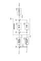
- FIG. 8 is a diagram showing an example of a system schematic configuration of a steering device for a vehicle of a steer-by-wire type according to an embodiment.
- the first ECU 51 for the reaction force device 60 and the second ECU 52 for the drive device 70 transmit and receive data via the communication line Lc.
- the first ECU 51 corresponds to the first control unit in the present disclosure. Further, the second ECU 52 corresponds to the second control unit in the present disclosure.
- the hardware configurations of the first ECU 51 and the second ECU 52 are the same as those shown in FIG. 2, and thus the description thereof will be omitted here.
- the steering angle ⁇ ha and the steering angle ⁇ hb which are the detected values of the first steering angle sensor 41 and the second steering angle sensor 42, are the driving device 70 (driving motor 71).
- the communication system including the communication line Lc with the first ECU 51 that controls the reaction force device 60 (reaction force motor 61) or the first ECU 51 fails by being input to the second ECU 52 that controls The operation can be continued by the device 70, and the fail-safe function of the vehicle system can be realized with a simple configuration. That is, in the configuration of the present embodiment shown in FIG. 8, as will be described later in FIG. 10, the second ECU 52 may have redundancy, and the first ECU 51 does not necessarily have to have redundancy.
- a mode of displaying on a display unit such as a meter panel a mode of causing a light emitting element such as an LED to emit light, or an alarm may be used. It may be a mode that emits a sound. It is not limited by the mode of processing at the time of abnormality in the second ECU 52.
- the rudder angle detection function may be further multiplexed to enhance redundancy.
- the elements to be multiplexed are not limited to the steering angle detection function, and may be, for example, a torque detection function corresponding to the torque sensor 10 shown in FIG. 1 or a configuration in which the power supply system supplied to each element is multiplexed.
- the internal configuration of the first ECU 51 and the second ECU 52 may be multiplexed.
- the hardware configuration provided on the semiconductor chips constituting the first ECU 51 and the second ECU 52 may be multiplexed, or a configuration in which a plurality of the same semiconductor chips are mounted may be used.
Landscapes
- Engineering & Computer Science (AREA)
- Chemical & Material Sciences (AREA)
- Combustion & Propulsion (AREA)
- Transportation (AREA)
- Mechanical Engineering (AREA)
- Steering Control In Accordance With Driving Conditions (AREA)
- Power Steering Mechanism (AREA)
Priority Applications (4)
| Application Number | Priority Date | Filing Date | Title |
|---|---|---|---|
| DE112020005378.4T DE112020005378T5 (de) | 2019-10-31 | 2020-10-08 | Fahrzeuglenkanlage |
| US17/642,754 US11975771B2 (en) | 2019-10-31 | 2020-10-08 | Vehicle steering device |
| CN202080075826.8A CN114616165B (zh) | 2019-10-31 | 2020-10-08 | 车辆用转向装置 |
| JP2021554259A JP7539909B2 (ja) | 2019-10-31 | 2020-10-08 | 車両用操向装置 |
Applications Claiming Priority (2)
| Application Number | Priority Date | Filing Date | Title |
|---|---|---|---|
| JP2019199286 | 2019-10-31 | ||
| JP2019-199286 | 2019-10-31 |
Publications (1)
| Publication Number | Publication Date |
|---|---|
| WO2021085070A1 true WO2021085070A1 (ja) | 2021-05-06 |
Family
ID=75715151
Family Applications (1)
| Application Number | Title | Priority Date | Filing Date |
|---|---|---|---|
| PCT/JP2020/038170 Ceased WO2021085070A1 (ja) | 2019-10-31 | 2020-10-08 | 車両用操向装置 |
Country Status (5)
| Country | Link |
|---|---|
| US (1) | US11975771B2 (https=) |
| JP (1) | JP7539909B2 (https=) |
| CN (1) | CN114616165B (https=) |
| DE (1) | DE112020005378T5 (https=) |
| WO (1) | WO2021085070A1 (https=) |
Cited By (2)
| Publication number | Priority date | Publication date | Assignee | Title |
|---|---|---|---|---|
| JP2023108207A (ja) * | 2022-01-25 | 2023-08-04 | 日本精工株式会社 | 車両制御システム及び転舵制御装置 |
| JP2024005645A (ja) * | 2022-06-30 | 2024-01-17 | 株式会社ジェイテクト | 車両用制御装置 |
Families Citing this family (2)
| Publication number | Priority date | Publication date | Assignee | Title |
|---|---|---|---|---|
| KR102167906B1 (ko) | 2019-06-20 | 2020-10-20 | 주식회사 만도 | 조향 제어 장치 및 이를 포함하는 조향 보조 시스템 |
| DE102023126410A1 (de) * | 2022-09-30 | 2024-04-04 | Steering Solutions Ip Holding Corporation | Systeme und verfahren zur bereitstellung von fahrerwarnungen unmittelbar nach einem ereignis |
Citations (5)
| Publication number | Priority date | Publication date | Assignee | Title |
|---|---|---|---|---|
| JP2003175846A (ja) * | 2001-12-10 | 2003-06-24 | Nissan Motor Co Ltd | 操舵制御装置 |
| JP2005053404A (ja) * | 2003-08-06 | 2005-03-03 | Koyo Seiko Co Ltd | 車両用操舵装置 |
| JP2006205878A (ja) * | 2005-01-27 | 2006-08-10 | Jtekt Corp | 車両用操舵装置 |
| JP2009248660A (ja) * | 2008-04-03 | 2009-10-29 | Nsk Ltd | 車両用電動式操舵装置 |
| JP2013028312A (ja) * | 2011-07-29 | 2013-02-07 | Ntn Corp | 冗長機能付きステアバイワイヤ式操舵装置の制御装置 |
Family Cites Families (15)
| Publication number | Priority date | Publication date | Assignee | Title |
|---|---|---|---|---|
| JP3871639B2 (ja) * | 2002-11-22 | 2007-01-24 | 株式会社ジェイテクト | 車両用操舵装置 |
| JP4449397B2 (ja) * | 2003-10-02 | 2010-04-14 | 日産自動車株式会社 | 車両用操舵装置 |
| JP4848027B2 (ja) * | 2004-01-30 | 2011-12-28 | 日立オートモティブシステムズ株式会社 | 車両制御装置 |
| JP4604750B2 (ja) | 2005-02-10 | 2011-01-05 | 株式会社ジェイテクト | 車両用操舵装置 |
| JP4725132B2 (ja) * | 2005-03-01 | 2011-07-13 | 日産自動車株式会社 | 操舵制御装置 |
| CN102026864B (zh) * | 2008-05-16 | 2013-03-06 | 本田技研工业株式会社 | 电动转向设备 |
| JP2010254266A (ja) * | 2009-03-30 | 2010-11-11 | Honda Motor Co Ltd | 車両の操舵制御装置 |
| JP5224419B2 (ja) * | 2011-02-09 | 2013-07-03 | 本田技研工業株式会社 | 電動パワーステアリング装置 |
| US9321480B2 (en) * | 2011-06-01 | 2016-04-26 | Toyota Jidosha Kabushiki Kaisha | Vehicle steering control apparatus |
| JP5971512B2 (ja) * | 2011-12-02 | 2016-08-17 | 株式会社ジェイテクト | 車両用操舵装置 |
| JP2014210496A (ja) * | 2013-04-18 | 2014-11-13 | 株式会社ジェイテクト | 油圧パワーステアリング装置の制御装置 |
| JP6583403B2 (ja) * | 2015-04-09 | 2019-10-02 | 日産自動車株式会社 | 車線維持支援装置 |
| CN108290606B (zh) * | 2015-12-10 | 2019-07-09 | 日本精工株式会社 | 电动助力转向装置 |
| DE102016009684A1 (de) * | 2016-08-10 | 2018-02-15 | Thyssenkrupp Ag | Regelung eines Steer-by-Wire-Lenksystems |
| JP2018052311A (ja) * | 2016-09-29 | 2018-04-05 | 日立オートモティブシステムズ株式会社 | アクチュエータシステム、異常検知装置 |
-
2020
- 2020-10-08 US US17/642,754 patent/US11975771B2/en active Active
- 2020-10-08 CN CN202080075826.8A patent/CN114616165B/zh active Active
- 2020-10-08 DE DE112020005378.4T patent/DE112020005378T5/de active Pending
- 2020-10-08 JP JP2021554259A patent/JP7539909B2/ja active Active
- 2020-10-08 WO PCT/JP2020/038170 patent/WO2021085070A1/ja not_active Ceased
Patent Citations (5)
| Publication number | Priority date | Publication date | Assignee | Title |
|---|---|---|---|---|
| JP2003175846A (ja) * | 2001-12-10 | 2003-06-24 | Nissan Motor Co Ltd | 操舵制御装置 |
| JP2005053404A (ja) * | 2003-08-06 | 2005-03-03 | Koyo Seiko Co Ltd | 車両用操舵装置 |
| JP2006205878A (ja) * | 2005-01-27 | 2006-08-10 | Jtekt Corp | 車両用操舵装置 |
| JP2009248660A (ja) * | 2008-04-03 | 2009-10-29 | Nsk Ltd | 車両用電動式操舵装置 |
| JP2013028312A (ja) * | 2011-07-29 | 2013-02-07 | Ntn Corp | 冗長機能付きステアバイワイヤ式操舵装置の制御装置 |
Cited By (3)
| Publication number | Priority date | Publication date | Assignee | Title |
|---|---|---|---|---|
| JP2023108207A (ja) * | 2022-01-25 | 2023-08-04 | 日本精工株式会社 | 車両制御システム及び転舵制御装置 |
| JP7774457B2 (ja) | 2022-01-25 | 2025-11-21 | Nskステアリング&コントロール株式会社 | 車両制御システム及び転舵制御装置 |
| JP2024005645A (ja) * | 2022-06-30 | 2024-01-17 | 株式会社ジェイテクト | 車両用制御装置 |
Also Published As
| Publication number | Publication date |
|---|---|
| CN114616165B (zh) | 2024-01-30 |
| US11975771B2 (en) | 2024-05-07 |
| CN114616165A (zh) | 2022-06-10 |
| JP7539909B2 (ja) | 2024-08-26 |
| JPWO2021085070A1 (https=) | 2021-05-06 |
| US20220332362A1 (en) | 2022-10-20 |
| DE112020005378T5 (de) | 2022-08-18 |
Similar Documents
| Publication | Publication Date | Title |
|---|---|---|
| JP7539909B2 (ja) | 車両用操向装置 | |
| US11597434B2 (en) | Steering control system | |
| EP3192722B1 (en) | Electric power steering device | |
| EP2116443B1 (en) | Electric power steering apparatus | |
| CN107914765B (zh) | 车辆用转向操纵装置 | |
| JPWO2020115973A1 (ja) | 車両用操向装置 | |
| CN114245781B (zh) | 转向控制装置、转向控制方法和转向支持系统 | |
| US12240546B2 (en) | Steering control device and standard value adjustment method | |
| JP2021160638A (ja) | 車両用操向装置 | |
| JP2020192908A (ja) | 車両用操向装置 | |
| US12559165B2 (en) | Apparatus and method for controlling steering of host vehicle | |
| KR102885651B1 (ko) | 조향 반력장치 고장시 조향 제어가능한 스티어 바이 와이어 시스템 및 그 조향 제어방법 | |
| JP5092509B2 (ja) | 電動パワーステアリング装置 | |
| KR100802741B1 (ko) | 듀얼모터식 좌우독립형 sbw 시스템의 듀얼모터 제어방법 | |
| JP2021147018A (ja) | 車両用操向装置 | |
| JP4380362B2 (ja) | 車両の転舵装置 | |
| JP2018076072A (ja) | 電動パワーステアリング装置の制御装置 | |
| JP4333399B2 (ja) | 車両操舵装置 | |
| JP4802641B2 (ja) | 車両用操舵装置 | |
| JP7846483B2 (ja) | 制御ユニット | |
| US20260103233A1 (en) | Steering control system and method | |
| JP4594129B2 (ja) | 車両の操舵装置 | |
| JP4474298B2 (ja) | 車両の操舵装置 | |
| JP4285369B2 (ja) | 車両の操舵装置 | |
| JP2018076073A (ja) | 電動パワーステアリング装置の制御装置 |
Legal Events
| Date | Code | Title | Description |
|---|---|---|---|
| 121 | Ep: the epo has been informed by wipo that ep was designated in this application |
Ref document number: 20882742 Country of ref document: EP Kind code of ref document: A1 |
|
| ENP | Entry into the national phase |
Ref document number: 2021554259 Country of ref document: JP Kind code of ref document: A |
|
| 122 | Ep: pct application non-entry in european phase |
Ref document number: 20882742 Country of ref document: EP Kind code of ref document: A1 |