WO2021075149A1 - レバー式コネクタ - Google Patents
レバー式コネクタ Download PDFInfo
- Publication number
- WO2021075149A1 WO2021075149A1 PCT/JP2020/031610 JP2020031610W WO2021075149A1 WO 2021075149 A1 WO2021075149 A1 WO 2021075149A1 JP 2020031610 W JP2020031610 W JP 2020031610W WO 2021075149 A1 WO2021075149 A1 WO 2021075149A1
- Authority
- WO
- WIPO (PCT)
- Prior art keywords
- lever
- housing
- axis
- fitting
- shaft
- Prior art date
Links
Images
Classifications
-
- H—ELECTRICITY
- H01—ELECTRIC ELEMENTS
- H01R—ELECTRICALLY-CONDUCTIVE CONNECTIONS; STRUCTURAL ASSOCIATIONS OF A PLURALITY OF MUTUALLY-INSULATED ELECTRICAL CONNECTING ELEMENTS; COUPLING DEVICES; CURRENT COLLECTORS
- H01R13/00—Details of coupling devices of the kinds covered by groups H01R12/70 or H01R24/00 - H01R33/00
- H01R13/62—Means for facilitating engagement or disengagement of coupling parts or for holding them in engagement
- H01R13/629—Additional means for facilitating engagement or disengagement of coupling parts, e.g. aligning or guiding means, levers, gas pressure electrical locking indicators, manufacturing tolerances
- H01R13/62933—Comprising exclusively pivoting lever
- H01R13/62966—Comprising two pivoting levers
-
- H—ELECTRICITY
- H01—ELECTRIC ELEMENTS
- H01R—ELECTRICALLY-CONDUCTIVE CONNECTIONS; STRUCTURAL ASSOCIATIONS OF A PLURALITY OF MUTUALLY-INSULATED ELECTRICAL CONNECTING ELEMENTS; COUPLING DEVICES; CURRENT COLLECTORS
- H01R13/00—Details of coupling devices of the kinds covered by groups H01R12/70 or H01R24/00 - H01R33/00
- H01R13/62—Means for facilitating engagement or disengagement of coupling parts or for holding them in engagement
- H01R13/629—Additional means for facilitating engagement or disengagement of coupling parts, e.g. aligning or guiding means, levers, gas pressure electrical locking indicators, manufacturing tolerances
- H01R13/62933—Comprising exclusively pivoting lever
- H01R13/62938—Pivoting lever comprising own camming means
-
- H—ELECTRICITY
- H01—ELECTRIC ELEMENTS
- H01R—ELECTRICALLY-CONDUCTIVE CONNECTIONS; STRUCTURAL ASSOCIATIONS OF A PLURALITY OF MUTUALLY-INSULATED ELECTRICAL CONNECTING ELEMENTS; COUPLING DEVICES; CURRENT COLLECTORS
- H01R13/00—Details of coupling devices of the kinds covered by groups H01R12/70 or H01R24/00 - H01R33/00
- H01R13/62—Means for facilitating engagement or disengagement of coupling parts or for holding them in engagement
- H01R13/629—Additional means for facilitating engagement or disengagement of coupling parts, e.g. aligning or guiding means, levers, gas pressure electrical locking indicators, manufacturing tolerances
- H01R13/62977—Pivoting levers actuating linearly camming means
Definitions
- This disclosure relates to a lever type connector.
- Patent Document 1 discloses a lever fitting type connector in which a rotatable lever is attached to a connector housing. When mating the lever fitting type connector with the mating connector, the lever is rotated while the driven pin of the mating connector is inserted into the cam hole of the lever. When the lever is operated to slide the cam hole and the driven pin into contact with each other, a boosting effect is exerted by the lever action, and the lever fitting type connector and the mating connector are fitted.
- the lever type connector of the present disclosure is completed based on the above circumstances, and an object thereof is to reduce the operating force without increasing the size.
- the lever type connector of the present disclosure is With the housing A first lever attached to the housing so that it can rotate about the first axis, A second lever attached to the housing so that it can rotate about the second axis, It is provided with a boosting function unit that exerts a boosting function by interlocking with the rotation of the second lever.
- the first lever has a guide portion extending from the operation portion of the first lever toward the first axis.
- the second lever has a connecting portion that is connected to the first lever so that it can be displaced relative to the guide portion.
- the first lever and the second lever are interlocked between an initial position at which the housing and the mating housing start to be fitted and a fitting position at which the housing and the mating housing are completed. It is rotatable and can be rotated. When a virtual line passing through the second axis and the connecting portion is set with the second lever in the initial position, the first axis is located closer to the fitting position than the virtual line.
- the operating force can be reduced without increasing the size.
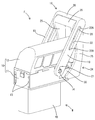
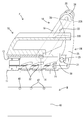
- FIG. 1 is a perspective view showing a state in which the lever type connector of the first embodiment and the mating connector are started to be fitted.
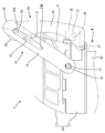
- FIG. 2 is a side view showing a state in which the first lever and the second lever are in the initial positions.
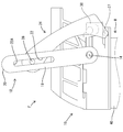
- FIG. 3 is a side view showing a state in which the first lever and the second lever are located between the initial position and the fitting position.
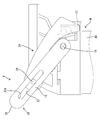
- FIG. 4 is a side view showing a state in which the first lever and the second lever are in the mating position.
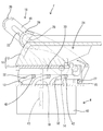
- FIG. 5 is a side sectional view showing a state in which the first lever and the second lever are in the initial positions and the lever type connector and the mating side connector are separated from each other.
- FIG. 6 is a side sectional view showing a state in which the first lever and the second lever are in the fitting position and the lever type connector and the mating side connector are fitted.
- the lever type connector of the present disclosure is (1) A housing, a first lever attached to the housing so as to rotate about the first axis, and a second lever attached to the housing so as to rotate about the second axis.
- a boosting function unit that exerts a boosting function by interlocking with the rotation of the second lever is provided, and the first lever is a guide portion extending from the operating portion of the first lever toward the first axis.
- the second lever has a connecting portion connected to the first lever so as to be relatively displaced along the guide portion, and the first lever and the second lever are the housing.
- the second lever can rotate in conjunction with the initial position at which the mating with the mating housing starts and the mating position at which the mating between the housing and the mating housing is completed.
- the first axis is located closer to the fitting position than the virtual line.
- the operating force applied to the operating portion is applied to the operating portion via the connecting portion and the second lever.
- the boosting function is exerted.
- the connecting portion is displaced relative to the first axis side from the operating portion side along the guide portion, so that the operating portion is displaced so as to move away from the second axis. Therefore, the operating force required to rotate the second shaft can be small. Since it is not necessary to lengthen the first lever and the second lever, the operating force can be reduced without increasing the size.
- the connecting portion is arranged at the tip end portion on the side opposite to the second axis in the length direction of the second lever. According to this configuration, the tip of the second lever does not protrude from the side edge of the first lever in the process of rotating the first lever and the second lever in conjunction with each other.
- the connecting portion is located at the operation side end portion of the both ends in the length direction of the guide portion, which is closer to the operation portion. It is preferable to do so. According to this configuration, when both levers in the initial position are to be rotated to the side opposite to the fitting position, the connecting portion abuts on the operation side end portion of the guide portion. As a result, it is possible to prevent both levers in the initial position from rotating to the side opposite to the fitting position.
- the operating portion is located at the tip of both ends of the first lever in the length direction opposite to the first axis, and the first shaft of both ends of the guide portion in the length direction. It is preferable that the operation side end portion on the opposite side to the operation portion is located adjacent to the operation portion. According to this configuration, the dimension in which the tip of the first lever protrudes from the side edge of the second lever when both levers are in the initial positions can be shortened.
- the connecting portion is preferably located on a straight line connecting the first axis and the second axis. .. According to this configuration, the direction of the operating force applied to the operation unit for rotating the first lever around the first axis coincides with the direction of rotating the second lever around the second axis. Therefore, the operating force applied to the operating unit is exerted as a force for rotating the second lever without loss.
- the lever type connector F of this embodiment is fitted so as to approach the mating connector M from above.
- the mating side connector M has a mating side housing 40 and a plurality of male terminal fittings 43 (see FIG. 6) housed inside the mating side housing 40.
- a plurality of (three in this embodiment) cam followers 42 are formed on the left and right outer surfaces of the mating connector M at intervals in the front-rear direction.
- the upper surface of the mating housing 40 is a fitting surface facing the lever type connector F.
- the lever-type connector F has one housing 10, a plurality of female terminal fittings 16 (see FIG. 6), one first lever 18, one second lever 24, and a pair of left and right sliders 30. ..
- the housing 10 has a two-part structure in which a housing body 11 made of synthetic resin and an electric wire cover 12 made of synthetic resin are assembled.
- a plurality of female terminal fittings 16 are housed in the housing body 11.
- the lower surface of the housing body 11 is a fitting surface that faces the fitting surface of the mating connector M in the vertical direction.
- An electric wire (not shown) connected to each female terminal fitting 16 is led out upward from the upper surface of the housing main body 11, that is, the outer surface on the side opposite to the fitting direction to the mating housing 40.
- An electric wire cover 12 is attached to the upper surface of the housing body 11. Inside the electric wire cover 12, a plurality of electric wires led out from the housing main body 11 are turned so as to bend rearward. The converted electric wire is pulled out to the rear of the electric wire cover 12.
- a pair of left and right guide grooves 13 are formed inside the housing body 11.
- the guide grooves 13 are arranged along the left and right outer surfaces of the housing main body 11 and extend in the front-rear direction orthogonal to the fitting direction of both connectors F and M. Both front and rear ends of the guide groove 13 are open to the outside of the housing body 11.
- first shaft 14 On both the left and right outer surfaces of the housing body 11, a pair of first axes 14 whose axes are directed in the left-right direction, that is, in the direction orthogonal to the fitting direction of both connectors F and M, are formed coaxially.
- the first shaft 14 In the front-rear direction, the first shaft 14 is arranged at a position in front of the center of the housing 10. In the vertical direction, the first shaft 14 is arranged above the central height of the housing body 11.
- a pair of bearing portions 15 are formed on both the left and right outer surfaces of the housing body 11.
- the bearing portion 15 In the front-rear direction, the bearing portion 15 is arranged at the rear end portion of the housing 10, that is, at a position rearward from the first shaft 14.
- the bearing portion 15 In the vertical direction, the bearing portion 15 is arranged at the lower end portion of the housing body 11, that is, at a position below the first shaft 14.
- the bearing portion 15 is arranged at a position obliquely downward and rearward with respect to the
- the first lever 18 is a single component having a pair of symmetrical first arm portions 19 and an operation portion 20 in which the tip portions of both first arm portions 19 are connected to each other.
- a bearing hole 21 is formed at the base end portion of the first arm portion 19 so as to penetrate the first arm portion 19 in the left-right direction.
- the first lever 18 is attached so as to be able to rotate relative to the housing 10 by fitting the bearing hole 21 into the first shaft 14.
- the first arm portion 19 is positioned so as to overlap the outer surface of the housing 10 with a clearance in the left-right direction.
- the first arm portion 19 has an elongated plate shape extending in a straight line.
- Guide portions 22 are formed on both the left and right first arm portions 19 so as to penetrate the first arm portions 19 to the left and right, respectively.
- the guide portion 22 extends linearly from the operation portion 20 side toward the first shaft 14 side in parallel with the first arm portion 19 to form a groove shape.
- the guide portion 22 is closed at the operation side end portion 22A on the side closer to the operation portion 20 and the shaft side end portion 22B near the first shaft 14 side of both ends in the length direction of the guide portion 22.
- the second lever 24 is a single component having a pair of symmetrical second arm portions 25 and a connecting portion 26 in which the tip portions of both second arm portions 25 are connected to each other.
- a pair of second shafts 27 are formed at the base ends of both the left and right second arm portions 25.
- the pair of second axes 27 have a form in which the axes project from the inner surface of the base end portion in the left-right direction, and are arranged coaxially with each other.
- the second lever 24 is attached so as to be able to rotate relative to the housing 10 by fitting the second shaft 27 to the bearing portion 15.
- the second arm portion 25 When the second lever 24 is attached to the housing 10, the second arm portion 25 is positioned so as to overlap the outer surface of the housing 10 with a clearance in the left-right direction, and is located on the inner surface of the first arm portion 19. On the other hand, it is located so that it overlaps with a clearance in the left-right direction.
- the second arm portion 25 has an elongated curved shape when viewed in parallel with the axis of the second axis 27.
- a pair of connecting portions 28 are formed at the tip portions of the pair of second arm portions 25.
- the pair of connecting portions 28 have a cylindrical shape with the axes oriented in the left-right direction, that is, in the direction parallel to the first axis 14 and the second axis 27.
- the pair of connecting portions 28 project in the left-right direction from the outer surface of the tip end portion of the second arm portion 25.
- the outer diameter of the connecting portion 28 is the same as the width dimension of the guide portion 22, or slightly smaller than the width dimension of the guide portion 22.
- a pair of drive shafts 29 are formed on both the left and right second levers 24.
- the drive shaft 29 is arranged between the center of the second lever 24 and the second shaft 27. That is, the length dimension from the second shaft 27 to the drive shaft 29 is shorter than the length dimension from the second shaft 27 to the connecting portion 28.
- the drive shaft 29 has a form in which the axis line is directed in the left-right direction and protrudes from the inner surface of the second arm portion 25.
- the first lever 18 and the second lever 24 are connected so that they can rotate in conjunction with each other while being relatively displaced by fitting the connecting portion 28 into the guide portion 22.
- the connected first lever 18 and second lever 24 rotate between the initial position shown in FIGS. 1, 2 and 5 and the fitting position shown in FIGS. 4 and 6.
- the first lever 18 and the first shaft 14 rotate around the first lever 18, and the second lever 24 rotates about the second shaft 27.
- the first lever 18 takes a backward tilted posture so that the operation unit 20 is located behind the first axis 14 and the second axis 27.
- the second lever 24 is tilted backward so that the connecting portion 28 is located behind the second shaft 27.
- the connecting portion 28 is located at the operation side end portion 22A of the guide portion 22.
- Both levers 18 and 24 in the initial position are displaced to the fitting position by rotating in the counterclockwise direction in the side view shown in FIGS. 2 to 6.
- the first lever 18 takes a forward tilted posture so that the operating portion 20 is positioned in front of the first shaft 14.
- the second lever 24 takes a forward tilted posture so that the connecting portion 28 is located in front of the first shaft 14 and the second shaft 27.
- the line connecting the connecting portion 28 and the second axis 27 is defined as the virtual line V.
- the front area is defined as the area on the fitting position side among the two areas on the front side and the rear side partitioned by the virtual line V.
- the region on the rear side is defined as the region on the initial position side.
- the region on the fitting position side is a region in which the connecting portion 28 moves when the second lever 24 at the initial position rotates toward the fitting position.
- the first axis 14 is located in the region on the fitting position side with respect to the virtual line V.
- the first axis 14 is located inside the locus circle drawn by the connecting portion 28 as the second lever 24 rotates.
- the operation unit 20 is located outside the locus circle drawn by the connecting unit 28.
- the pair of sliders 30 are mounted in the guide groove 13 of the housing body 11 so as to be relatively displaced in the front-rear direction.
- a passive recess 31 is formed at the rear end of the slider 30.
- the slider 30 is formed with a plurality of (three in this embodiment) cam grooves 32 that function as boosting function units.
- the cam groove 32 has a groove portion in an oblique direction with respect to both the fitting direction of both connectors F and M and the moving direction of the slider 30.
- the entrance of the cam groove 32 is open to the lower end edge of the slider 30.
- the slider 30 is connected to the second lever 24 by fitting the passive recess 31 to the drive shaft 29.
- the second lever 24 can rotate relative to the slider 30 about the drive shaft 29.
- the operating force applied to the operating portion 20 of the first lever 18 acts as a rotational force with respect to the second lever 24 by passing through the guide portion 22 and the connecting portion 28. Be transmitted. Since the first axis 14 is arranged on the fitting position side with respect to the virtual line V, in the process in which both levers 18 and 24 rotate in the fitting direction, the connecting portion 28 moves along the guide portion 22 on the operating side. The relative displacement is performed from the end portion 22A toward the shaft side end portion 22B. As the connecting portion 28 moves toward the shaft side end portion 22B, the operating portion 20 moves away from the outer peripheral side with respect to the locus circle (not shown) drawn by the connecting portion 28 about the second axis 27. Displace relative to. As a result, the distance from the second shaft 27, which is interlocked with the boosting function, to the operating unit 20 to which the operating force is applied becomes long, so that the operating force required for the cam groove 32 to exert the boosting function is increased. It becomes smaller.
- the connecting portion 28 is a portion for transmitting rotational power from the first lever 18 to the second lever 24, when the first lever 18 is used as a lever and the first shaft 14 is used as a fulcrum for the lever,
- the connecting portion 28 is the point of action of the lever.
- the operation unit 20 is the point of effort of the lever, and the position of the operation unit 20 does not change even if the first lever 18 rotates.
- the connecting portion 28, which is the point of action approaches the first axis 14, which is the fulcrum of the lever, as both levers 18 and 24 rotate toward the fitting position side. Therefore, the boosting function when the operating force applied to the operating unit 20 is transmitted to the second lever 24 increases as the rotation of both levers 18 and 24 toward the fitting position progresses. ..
- the first lever 18 and the second lever 24 rotate relative to each other around the connecting portion 28.
- the angle ⁇ formed by the half straight line from the connecting portion 28 to the first axis 14 and the virtual line V from the connecting portion 28 to the second axis 27 fluctuates as it goes to the fitting position.
- the direction in which the second lever 24 rotates is a direction perpendicular to the virtual line V connecting the second shaft 27 and the connecting portion 28.
- the rotational power transmitted to the second lever 24 is transmitted to the slider 30 via the drive shaft 29 and the passive recess 31, and the slider 30 slides forward.
- the connecting portion 28 becomes the power point of the lever and the drive shaft 29 becomes the action point of the lever. Since the length from the second shaft 27 to the drive shaft 29 is shorter than the length from the second shaft 27 to the connecting portion 28, the driving force transmitted from the second lever 24 to the slider 30 is amplified by the action of the lever. Will be done.
- the first axis 14 is a region on the fitting position side with respect to the virtual line V connecting the second axis 27 and the connecting portion 28. It is kept in the state of being located in.
- the first shaft 14, the second shaft 27, and the connecting portion 28 are arranged so as to be substantially aligned with each other. This form means that the direction of the operating force acting on the operating unit 20 and the rotating direction of the second lever 24 are substantially parallel to each other. Therefore, the operating force applied to the operating unit 20 is transmitted as a driving force for rotating the second lever 24 as it is.
- the fitting resistance generated in the fitting process between the housing 10 and the mating housing 40 is maximized.
- the lever type connector F of this embodiment includes a housing 10, a first lever 18, a second lever 24, and a cam groove 32.
- the first lever 18 is attached to the housing 10 so as to be able to rotate about the first shaft 14.
- the second lever 24 is attached to the housing 10 so as to be able to rotate about the second shaft 27.
- the cam groove 32 is a boosting function unit that exerts a boosting function by interlocking with the rotation of the second lever 24.
- the first lever 18 has a guide portion 22 extending from the operation portion 20 of the first lever 18 toward the first shaft 14.
- the second lever 24 has a connecting portion 28 that is connected to the first lever 18 so as to be relatively displaced along the guide portion 22.
- the connecting portion 28 By fitting the connecting portion 28 into the guide portion 22, the first lever 18 and the second lever 24 are at the initial position where the housing 10 and the mating side housing 40 start to fit, and the housing 10 and the mating side housing 40. It rotates in conjunction with the fitting position that completes the fitting with.
- the first axis 14 is arranged in the area closer to the fitting position than the virtual line V. There is.
- the operating force applied to the operating portion 20 is applied to the connecting portion 28.
- the boosting function is exhibited by being transmitted to the second shaft 27 via the second lever 24.
- the connecting portion 28 is displaced relative to the first shaft 14 side from the operating portion 20 side along the guide portion 22, so that the operating portion 20 is displaced so as to move away from the second shaft 27. Therefore, the operating force required to rotate the second shaft 27 can be small. Since it is not necessary to lengthen the first lever 18 and the second lever 24, the operating force can be reduced without increasing the size.
- the connecting portion 28 is arranged at the tip end portion on the side opposite to the second axis 27 in the length direction of the second lever 24. According to this configuration, the tip of the second lever 24 does not protrude from the side edge of the first lever 18 in the process of rotating the first lever 18 and the second lever 24 in conjunction with each other.
- the connecting portion 28 In the state where the first lever 18 and the second lever 24 are in the initial positions, the connecting portion 28 is located at the operation side end portion 22A on the side closer to the operation portion 20 among both ends in the length direction of the guide portion 22. .. According to this configuration, when both levers 18 and 24 in the initial position are to be rotated to the side opposite to the fitting position, the connecting portion 28 abuts on the operating side end portion 22A of the guide portion 22. As a result, it is possible to prevent both levers 18 and 24 in the initial position from rotating to the side opposite to the fitting position.
- the operation unit 20 is located at the tip of the first lever 18 at both ends in the length direction opposite to the first axis 14. Of both ends of the guide portion 22 in the length direction, the operation side end portion 22A opposite to the first shaft 14 is located adjacent to the operation portion 20.
- the direction in which the operation side end 22A and the operation unit 20 are adjacent to each other is the length direction of the first lever 18, that is, the direction connecting the first shaft 14 and the operation unit 20. According to this configuration, when both levers 18 and 24 are in the initial positions, the dimension in which the tip of the first lever 18 protrudes from the side edge of the second lever 24 can be shortened.
- the connecting portion 28 is located on a straight line connecting the first shaft 14 and the second shaft 27. According to this configuration, the direction of the operating force applied to the operation unit 20 for rotating the first lever 18 around the first axis 14 rotates the second lever 24 around the second axis 27. Match the orientation. Therefore, the operating force applied to the operating unit 20 is exerted as a force for rotating the second lever 24 without loss.
- the connecting portion is arranged at the tip of the second lever, but the connecting portion may be arranged at a position closer to the second axis than the tip of the second lever.
- the connecting portion when both levers are in the initial position, the connecting portion is located at the operating side end of the guide portion, but when both levers are in the initial position, the connecting portion is located at the operating side end of the guide portion. It may be located on the first axis side.
- the operation unit is arranged at the tip of the first lever, but the operation unit may be arranged at a position closer to the first axis than the tip of the first lever.
- the operation side end portion of the guide portion is arranged so as to be adjacent to the operation portion, but the operation side end portion of the guide portion may be arranged at a position away from the operation portion.
- the rotational power of the second lever is transmitted to the slider, and the cam groove formed in the slider exerts a boosting function.
- a cam groove as a boosting function portion may be formed in the second lever. ..
- the first axis when both levers are located between the initial position and the fitting position, the first axis is located in the area on the fitting position side of the virtual line connecting the second axis and the connecting portion.
- the first axis may be located in the region on the initial position side of the virtual line while both levers are from the initial position to the fitting position.
Landscapes
- Details Of Connecting Devices For Male And Female Coupling (AREA)
Abstract
大型化することなく操作力を低減する。 レバー式コネクタ(F)は、第1軸(14)を中心に回動する第1レバー(18)と、第2軸(27)を中心に回動する第2レバー(24)と、第2レバー(24)の回動に連動するカム溝(32)を備える。第1レバー(18)は、操作部(20)から第1軸(14)に向かって延びるガイド部(22)を有し、第2レバー(24)は、第1レバー(18)に対しガイド部(22)に沿って相対変位し得るように連結された連結部(28)を有する。両レバー(18,24)は、ハウジング(10)と相手側ハウジング(40)との嵌合を開始する初期位置と、ハウジング(10)と相手側ハウジング(40)との嵌合を完了する嵌合位置との間で連動して回動する。第2レバー(24)が初期位置にある状態で第2軸(27)と連結部(28)を通る仮想線(V)を設定したときに、第1軸(14)は仮想線(V)よりも嵌合位置側に位置する。
Description
本開示は、レバー式コネクタに関するものである。
特許文献1には、コネクタハウジングに回動可能なレバーを取り付けたレバー嵌合式コネクタが開示されている。このレバー嵌合式コネクタと相手側コネクタを嵌合する際には、レバーのカム孔に相手側コネクタの従動ピンを挿入した状態で、レバーを回動操作する。レバーを操作してカム孔と従動ピンを摺接させると、テコ作用によって倍力効果が発揮され、レバー嵌合式コネクタと相手側コネクタが嵌合する。
レバーに付与する操作力を低減するためには、レバーの支点から操作部までの長さ寸法を大きく確保すればよい。しかし、レバーの支点から操作部までを長くすると、レバー嵌合式コネクタが大型化する。
本開示のレバー式コネクタは、上記のような事情に基づいて完成されたものであって、大型化することなく操作力を低減することを目的とする。
本開示のレバー式コネクタは、
ハウジングと、
第1軸を中心として回動し得るように前記ハウジングに取り付けた第1レバーと、
第2軸を中心として回動し得るように前記ハウジングに取り付けた第2レバーと、
前記第2レバーの回動に連動することによって倍力機能を発揮する倍力機能部とを備え、
前記第1レバーは、前記第1レバーの操作部から前記第1軸に向かって延びるガイド部を有し、
前記第2レバーは、前記第1レバーに対し前記ガイド部に沿って相対変位し得るように連結された連結部を有し、
前記第1レバーと前記第2レバーは、前記ハウジングと相手側ハウジングとの嵌合を開始する初期位置と、前記ハウジングと前記相手側ハウジングとの嵌合を完了する嵌合位置との間で連動して回動可能であり、
前記第2レバーが前記初期位置にある状態で前記第2軸と前記連結部を通る仮想線を設定したときに、前記第1軸は前記仮想線よりも前記嵌合位置側に位置する。
本開示によれば、大型化することなく操作力を低減することができる。
[本開示の実施形態の説明]
最初に本開示の実施形態を列記して説明する。
本開示のレバー式コネクタは、
(1)ハウジングと、第1軸を中心として回動し得るように前記ハウジングに取り付けた第1レバーと、第2軸を中心として回動し得るように前記ハウジングに取り付けた第2レバーと、前記第2レバーの回動に連動することによって倍力機能を発揮する倍力機能部とを備え、前記第1レバーは、前記第1レバーの操作部から前記第1軸に向かって延びるガイド部を有し、前記第2レバーは、前記第1レバーに対し前記ガイド部に沿って相対変位し得るように連結された連結部を有し、前記第1レバーと前記第2レバーは、前記ハウジングと相手側ハウジングとの嵌合を開始する初期位置と、前記ハウジングと前記相手側ハウジングとの嵌合を完了する嵌合位置との間で連動して回動可能であり、前記第2レバーが前記初期位置にある状態で前記第2軸と前記連結部を通る仮想線を設定したときに、前記第1軸は前記仮想線よりも前記嵌合位置側に位置する。
本開示の構成によれば、第1レバーと第2レバーを初期位置から嵌合位置側へ回動させる過程では、操作部に付与した操作力が、連結部と第2レバーを介して第2軸に伝達されることによって、倍力機能が発揮される。この間、連結部が、ガイド部に沿って操作部側から第1軸側へ相対変位するので、操作部は、第2軸から遠ざかるように変位する。したがって、第2軸を回動させるために必要な操作力が小さくて済む。第1レバーと第2レバーを長くする必要がないので、大型化することなく操作力を低減することができる。
(2)前記連結部が、前記第2レバーの長さ方向における前記第2軸とは反対側の先端部に配置されていることが好ましい。この構成によれば、第1レバーと第2レバーが連動して回動する過程で、第2レバーの先端部が第1レバーの側縁から突出することがない。
(3)前記第1レバーと前記第2レバーが前記初期位置にある状態では、前記連結部が、前記ガイド部の長さ方向両端部のうち前記操作部に近い側の操作側端部に位置していることが好ましい。この構成によれば、初期位置にある両レバーを、嵌合位置とは反対側へ回動させようとすると、連結部がガイド部の操作側端部に突き当たる。これにより、初期位置の両レバーが嵌合位置とは反対側へ回動することを防止できる。
(4)前記操作部が、前記第1レバーの長さ方向両端部のうち前記第1軸とは反対側の先端部に位置し、前記ガイド部の長さ方向両端部のうち前記第1軸とは反対側の操作側端部が、前記操作部と隣り合うように位置していることが好ましい。この構成によれば、両レバーが初期位置にあるときに、第2レバーの側縁から第1レバーの先端部が突出する寸法を、短くすることができる。
(5)前記ハウジングと前記相手側ハウジングの嵌合過程で生じる嵌合抵抗が最大のときに、前記連結部が、前記第1軸と前記第2軸とを結ぶ直線上に位置することが好ましい。この構成によれば、第1軸を中心として第1レバーを回動させるための操作部に付与する操作力の向きが、第2軸を中心として第2レバーを回動させる向きと一致する。したがって、操作部に付与した操作力が、ロスなく第2レバーを回動させるための力として発揮される。
[本開示の実施形態の詳細]
[実施例1]
本開示のレバー式コネクタFを具体化した実施例1を、図1~図6を参照して説明する。なお、本発明はこれらの例示に限定されるものではなく、特許請求の範囲によって示され、特許請求の範囲と均等の意味および範囲内でのすべての変更が含まれることが意図される。本実施例1において、前後の方向については、図2~6における左方を前方と定義する。上下の方向については、図1~6にあらわれる向きを、そのまま上方、下方と定義する。
[実施例1]
本開示のレバー式コネクタFを具体化した実施例1を、図1~図6を参照して説明する。なお、本発明はこれらの例示に限定されるものではなく、特許請求の範囲によって示され、特許請求の範囲と均等の意味および範囲内でのすべての変更が含まれることが意図される。本実施例1において、前後の方向については、図2~6における左方を前方と定義する。上下の方向については、図1~6にあらわれる向きを、そのまま上方、下方と定義する。
本実施例のレバー式コネクタFは、相手側コネクタMに対し上方から接近させるようにして嵌合される。相手側コネクタMは、相手側ハウジング40と、相手側ハウジング40の内部に収容した複数の雄端子金具43(図6を参照)とを有する。図5,6に示すように、相手側コネクタMの左右両外側面には、それぞれ、複数(本実施例では3つ)のカムフォロア42が前後方向に間隔を空けて形成されている。相手側ハウジング40の上面は、レバー式コネクタFと対向する嵌合面となっている。
レバー式コネクタFは、1つのハウジング10と、複数の雌端子金具16(図6を参照)と、1つの第1レバー18と、1つの第2レバー24と、左右一対のスライダ30とを有する。ハウジング10は、合成樹脂製のハウジング本体11と、合成樹脂製の電線カバー12とを組み付けた2部品構造である。ハウジング本体11内には複数の雌端子金具16が収容されている。ハウジング本体11の下面は、相手側コネクタMの嵌合面に対し上下方向に対向する嵌合面となっている。
ハウジング本体11の上面、即ち相手側ハウジング40への嵌合方向とは反対側の外面からは、各雌端子金具16に接続した電線(図示省略)が上方へ導出されている。ハウジング本体11の上面には電線カバー12が取り付けられている。電線カバー12の内部では、ハウジング本体11から導出された複数本の電線が、後方へ屈曲するように転向させられている。転向した電線は、電線カバー12の後方へ外部へ引き出されている。
図5,6に示すように、ハウジング本体11の内部には左右一対のガイド溝13が形成されている。ガイド溝13は、ハウジング本体11の左右両外側面に沿うように配され、両コネクタF,Mの嵌合方向と直交する前後方向に延びている。ガイド溝13の前後両端は、ハウジング本体11の外部へ開放されている。
ハウジング本体11の左右両外側面には、軸線を左右方向、即ち両コネクタF,Mの嵌合方向と直交する方向に向けた一対の第1軸14が、同軸状に形成されている。前後方向において、第1軸14は、ハウジング10の中央よりも前方の位置に配置されている。上下方向において、第1軸14は、ハウジング本体11の中央高さよりも上方に配置されている。ハウジング本体11の左右両外側面には、一対の軸受部15(図6を参照)が形成されている。前後方向において、軸受部15は、ハウジング10の後端部、即ち第1軸14よりも後方の位置に配置されている。上下方向において、軸受部15は、ハウジング本体11の下端部、即ち第1軸14よりも下方の位置に配置されている。軸受部15は、第1軸14に対して斜め下後方へ離隔した位置に配置されている。
第1レバー18は、左右対称な一対の第1アーム部19と、両第1アーム部19の先端部同士を連結した形態の操作部20とを有する単一部品である。第1アーム部19の基端部には、第1アーム部19を左右方向に貫通した形態の軸受孔21が形成されている。第1レバー18は、軸受孔21を第1軸14に嵌合することにより、ハウジング10に対して相対的に回動し得るように取り付けられている。第1レバー18をハウジング10に取り付けた状態では、第1アーム部19が、ハウジング10の外側面に対し左右方向のクリアランスを空けて重なるように位置する。
第1アーム部19は、直線状に延びた細長い板状をなす。左右両第1アーム部19には、それぞれ、第1アーム部19を左右に貫通した形態のガイド部22が形成されている。ガイド部22は、操作部20側から第1軸14側に向かって第1アーム部19と平行に直線状に延び溝状をなす。ガイド部22は、ガイド部22の長さ方向両端部のうち操作部20に近い側の操作側端部22Aと、第1軸14側に近い軸側端部22Bにおいて閉じている。
第2レバー24は、左右対称な一対の第2アーム部25と、両第2アーム部25の先端部同士を連結した形態の繋ぎ部26とを有する単一部品である。左右両第2アーム部25の基端部には、一対の第2軸27が形成されている。一対の第2軸27は、軸線を左右方向に向けて基端部の内面から突出した形態であり、互いに同軸状に配置されている。第2レバー24は、第2軸27を軸受部15に嵌合することにより、ハウジング10に対して相対的に回動し得るように取り付けられている。第2レバー24をハウジング10に取り付けた状態では、第2アーム部25が、ハウジング10の外側面に対し左右方向のクリアランスを空けて重なるように位置するとともに、第1アーム部19の内側面に対して左右方向のクリアランスを空けて重なるように位置する。
第2アーム部25は、第2軸27の軸線と平行に見た側面視において、細長く湾曲した形状である。一対の第2アーム部25の先端部には、一対の連結部28が形成されている。一対の連結部28は、軸線を左右方向、即ち第1軸14及び第2軸27と平行な方向を向けた円柱形をなす。一対の連結部28は、第2アーム部25の先端部の外側面から左右方向へ突出している。連結部28の外径寸法は、ガイド部22の幅寸法と同じ寸法か、ガイド部22の幅寸法よりも僅かに小さい寸法である。
左右両第2レバー24には、一対の駆動軸29が形成されている。第2レバー24の長さ方向において、駆動軸29は、第2レバー24の中央と第2軸27との間に配置されている。つまり、第2軸27から駆動軸29までの長さ寸法は、第2軸27から連結部28までの長さ寸法よりも短い。駆動軸29は、軸線を左右方向に向けて第2アーム部25の内面から突出した形態である。
第1レバー18と第2レバー24は、連結部28をガイド部22に嵌入することによって、相対的に変位しつつ連動して回動し得るように連結されている。連結された第1レバー18と第2レバー24は、図1,2,5に示す初期位置と図4,6に示す嵌合位置との間で回動するようになっている。連動して回動する際には、第1レバー18と第1軸14を中心として回動し、第2レバー24は第2軸27を中心として回動する。
両レバー18,24が初期位置にあるときに、第1レバー18は、操作部20が第1軸14及び第2軸27よりも後方に位置するように後傾した姿勢をとる。第2レバー24は、連結部28が第2軸27よりも後方に位置するように後傾している。連結部28は、ガイド部22の操作側端部22Aに位置している。初期位置にある両レバー18,24は、図2~6に示す側面視において反時計周り方向へ回動させることにより、嵌合位置へ変位する。両レバー18,24が嵌合位置へ回動した状態では、第1レバー18は、操作部20が第1軸14よりも前方に位置するように前傾した姿勢をとる。第2レバー24は、連結部28が第1軸14及び第2軸27よりも前方に位置するように前傾した姿勢をとる。
両レバー18,24が初期位置にある状態において、連結部28と第2軸27を結んだ線を仮想線Vと定義する。第1軸14及び第2軸27の軸線と平行に見た側面視において、仮想線Vによって区画される前側と後側の2つの領域のうち、前側の領域を嵌合位置側の領域と定義する。仮想線Vによって区画される前側と後側の2つの領域のうち、後側の領域を初期位置側の領域と定義する。嵌合位置側の領域は、初期位置にある第2レバー24が嵌合位置に向かって回動するときに、連結部28が移動する領域である。両レバー18,24が初期位置にあるときに、第1軸14は仮想線Vよりも嵌合位置側の領域内に位置する。第1軸14は、第2レバー24の回動に伴って連結部28が描く軌跡円の内側に位置する。操作部20は、連結部28が描く軌跡円の外側に位置する。
一対のスライダ30は、ハウジング本体11のガイド溝13内に前後方向への相対変位を可能に取り付けられている。スライダ30の後端部には、受動凹部31が形成されている。図5,6に示すように、スライダ30には、倍力機能部として機能する複数(本実施例では3つ)のカム溝32が形成されている。カム溝32は、両コネクタF,Mの嵌合方向及びスライダ30の移動方向の両方向に対して斜め方向の溝部を有する。カム溝32の入口は、スライダ30の下端縁に開放されている。スライダ30は、受動凹部31を駆動軸29に嵌合させることにより、第2レバー24に連結されている。第2レバー24は、スライダ30に対して駆動軸29を中心として相対的に回動し得るようになっている。
レバー式コネクタFと相手側コネクタMを嵌合する際には、図5に示すように、両レバー18,24を初期位置に変位させた状態から、図2に示すように、相手側ハウジング40をハウジング10と浅く嵌合させる。両ハウジング10,40を浅く嵌合させると、カムフォロア42がカム溝32の入口に進入する。この状態から、第1レバー18の操作部20に操作力を加えて両レバー18,24を嵌合位置側へ回動させる。操作部20に付与される操作力の向きは、第1レバー18の長さ方向、即ち、第1軸14と操作部20を結んだ方向に対して直角な方向である。
両レバー18,24が回動する過程では、第1レバー18の操作部20に付与した操作力が、ガイド部22と連結部28を介すことにより、第2レバー24に対して回動力として伝達される。第1軸14は仮想線Vよりも嵌合位置側に配置されているので、両レバー18,24が嵌合方向へ回動する過程では、連結部28が、ガイド部22に沿って操作側端部22Aから軸側端部22Bに向かって相対変位する。連結部28が軸側端部22Bに向かって移動するのに伴い、操作部20は、連結部28が第2軸27を中心として描く軌跡円(図示省略)に対して、外周側へ遠ざかる方向へ相対的に変位する。これにより、倍力機能と連動する第2軸27から、操作力の付与対象である操作部20までの距離が長くなるので、カム溝32に倍力機能を発揮させるために必要な操作力が小さくなる。
また、連結部28の位置は、第1レバー18から第2レバー24へ回動力を伝達する部位であるから、第1レバー18をテコとし、第1軸14をテコの支点としたときに、連結部28はテコの作用点である。操作部20はテコの力点であり、操作部20の位置は第1レバー18が回動しても変化しない。作用点である連結部28は、両レバー18,24が嵌合位置側へ回動するのに伴って、テコの支点である第1軸14に接近していく。したがって、操作部20に付与した操作力を第2レバー24に伝達するときの倍力機能は、両レバー18,24の嵌合位置側への回動が進むのに伴って、増大していく。
また、第1レバー18と第2レバー24が初期位置から嵌合位置へ回動する過程では、第1レバー18と第2レバー24が、連結部28を中心として相対的に回動する。図2に示すように、連結部28から第1軸14に向かう半直線と、連結部28から第2軸27に向かう仮想線Vのなす角度θは、嵌合位置へ向かうのに伴って変動する。この連結部28を頂点として両レバー18,24のなす角度θが小さくなるほど、操作部20に作用する操作力の向きと、第2レバー24が回動する向きとのなす角度が、小さくなる。第2レバー24が回動する方向は、第2軸27と連結部28とを結んだ仮想線Vに対して直角な方向である。
第2レバー24に伝達された回動力は、駆動軸29と受動凹部31を介してスライダ30に伝達され、スライダ30は前方へスライドする。第2レバー24をテコとし、第2軸27をテコの支点としたときに、連結部28がテコの力点となり、駆動軸29がテコの作用点となる。第2軸27から駆動軸29までの長さは、第2軸27から連結部28までの長さよりも短いので、第2レバー24からスライダ30に伝達される駆動力は、テコの作用によって増幅される。
スライダ30がスライドすると、カムフォロア42がカム溝32の内側縁部に摺接することによって、相手側ハウジング40がハウジング10側へ引き込まれ、両コネクタF,Mの嵌合が進む。この間、カムフォロア42とカム溝32の摺接によって、倍力機能が発揮されるので、第2レバー24からスライダ30に付与すべき駆動力は小さくて済む。両レバー18,24が嵌合位置に到達すると、両コネクタF,Mが正規嵌合状態となる。
両レバー18,24が初期位置と嵌合位置との間に位置する状態では、第1軸14は、第2軸27と連結部28とを結んだ仮想線Vよりも嵌合位置側の領域に位置する状態に保たれる。両レバー18,24が嵌合位置に到達すると、第1軸14と第2軸27と連結部28とが、ほぼ一直線状に並ぶように配置される。この形態は、操作部20に作用する操作力の向きと、第2レバー24の回動方向とが、ほぼ平行になることを意味する。したがって、操作部20に付与された操作力が、そのまま第2レバー24に対して回動させるための駆動力として伝達される。本実施例では、両レバー18,24が嵌合位置に到達するときに、ハウジング10と相手側ハウジング40の嵌合過程で生じる嵌合抵抗が最大となる。
本実施例のレバー式コネクタFは、ハウジング10と、第1レバー18と、第2レバー24と、カム溝32とを備えている。第1レバー18は、第1軸14を中心として回動し得るようにハウジング10に取り付けられている。第2レバー24は、第2軸27を中心として回動し得るようにハウジング10に取り付けられている。カム溝32は、第2レバー24の回動に連動することによって倍力機能を発揮する倍力機能部である。
第1レバー18は、第1レバー18の操作部20から第1軸14に向かって延びるガイド部22を有している。第2レバー24は、第1レバー18に対しガイド部22に沿って相対変位し得るように連結された連結部28を有している。連結部28をガイド部22に嵌合することにより、第1レバー18と第2レバー24は、ハウジング10と相手側ハウジング40との嵌合を開始する初期位置と、ハウジング10と相手側ハウジング40との嵌合を完了する嵌合位置との間で連動して回動する。第2レバー24が初期位置にある状態で第2軸27と連結部28を通る仮想線Vを設定したときに、第1軸14は仮想線Vよりも嵌合位置側の領域に配置されている。
本実施例のレバー式コネクタFによれば、第1レバー18と第2レバー24を初期位置から嵌合位置側へ回動させる過程では、操作部20に付与した操作力が、連結部28と第2レバー24を介して第2軸27に伝達されることによって、倍力機能が発揮される。この間、連結部28が、ガイド部22に沿って操作部20側から第1軸14側へ相対変位するので、操作部20は、第2軸27から遠ざかるように変位する。したがって、第2軸27を回動させるために必要な操作力が小さくて済む。第1レバー18と第2レバー24を長くする必要がないので、大型化することなく操作力を低減することができる。
連結部28は、第2レバー24の長さ方向における第2軸27とは反対側の先端部に配置されている。この構成によれば、第1レバー18と第2レバー24が連動して回動する過程で、第2レバー24の先端部が第1レバー18の側縁から突出することがない。
第1レバー18と第2レバー24が初期位置にある状態では、連結部28が、ガイド部22の長さ方向両端部のうち操作部20に近い側の操作側端部22Aに位置している。この構成によれば、初期位置にある両レバー18,24を、嵌合位置とは反対側へ回動させようとすると、連結部28がガイド部22の操作側端部22Aに突き当たる。これにより、初期位置の両レバー18,24が嵌合位置とは反対側へ回動することを防止できる。
操作部20は、第1レバー18の長さ方向両端部のうち第1軸14とは反対側の先端部に位置している。ガイド部22の長さ方向両端部のうち第1軸14とは反対側の操作側端部22Aが、操作部20と隣り合うように位置している。操作側端部22Aと操作部20が隣り合う方向は、第1レバー18の長さ方向、即ち第1軸14と操作部20とを結ぶ方向である。この構成によれば、両レバー18,24が初期位置にあるときに、第2レバー24の側縁から第1レバー18の先端部が突出する寸法を、短くすることができる。
ハウジング10と相手側ハウジング40の嵌合過程で生じる嵌合抵抗が最大のときに、連結部28が、第1軸14と第2軸27とを結ぶ直線上に位置する。この構成によれば、第1軸14を中心として第1レバー18を回動させるための操作部20に付与する操作力の向きが、第2軸27を中心として第2レバー24を回動させる向きと一致する。したがって、操作部20に付与した操作力が、ロスなく第2レバー24を回動させるための力として発揮される。
[他の実施例]
本発明は、上記記述及び図面によって説明した実施例に限定されるものではなく、特許請求の範囲によって示される。本発明には、特許請求の範囲と均等の意味及び特許請求の範囲内でのすべての変更が含まれ、下記のような実施形態も含まれることが意図される。
上記実施例では、連結部を第2レバーの先端部に配置したが、連結部は、第2レバーの先端部よりも第2軸側の位置に配置してもよい。
上記実施例では、両レバーが初期位置にあるときに、連結部がガイド部の操作側端部に位置するが、両レバーが初期位置にあるときに、連結部はガイド部の操作側端部よりも第1軸側に位置してもよい。
上記実施例では、操作部を第1レバーの先端部に配置したが、操作部は、第1レバーの先端部よりも第1軸に近い位置に配置してもよい。
上記実施例では、ガイド部の操作側端部を、操作部と隣り合うように配置したが、ガイド部の操作側端部は、操作部から離れた位置に配置してもよい。
上記実施例では、第2レバーの回動力がスライダに伝達され、スライダに形成したカム溝が倍力機能を発揮するが、第2レバーに倍力機能部としてのカム溝を形成してもよい。
上記実施例では、両レバーが初期位置と嵌合位置との間に位置する状態では、第1軸が、第2軸と連結部とを結んだ仮想線よりも嵌合位置側の領域に位置するが、両レバーが初期位置から嵌合位置に至る間に、第1軸が上記仮想線よりも初期位置側の領域に位置するようになっていてもよい。
10…ハウジング
11…ハウジング本体
12…電線カバー
13…ガイド溝
14…第1軸
15…軸受部
16…雌端子金具
18…第1レバー
19…第1アーム部
20…操作部
21…軸受孔
22…ガイド部
22A:操作側端部
22B:軸側端部
24…第2レバー
25…第2アーム部
26…繋ぎ部
27…第2軸
28…連結部
29…駆動軸
30…スライダ
31…受動凹部
32…カム溝(倍力機能部)
40…相手側ハウジング
42…カムフォロア
43…雄端子金具
F…レバー式コネクタ
M…相手側コネクタ
V…仮想線
θ…第1レバーと第2レバーのなす角度
11…ハウジング本体
12…電線カバー
13…ガイド溝
14…第1軸
15…軸受部
16…雌端子金具
18…第1レバー
19…第1アーム部
20…操作部
21…軸受孔
22…ガイド部
22A:操作側端部
22B:軸側端部
24…第2レバー
25…第2アーム部
26…繋ぎ部
27…第2軸
28…連結部
29…駆動軸
30…スライダ
31…受動凹部
32…カム溝(倍力機能部)
40…相手側ハウジング
42…カムフォロア
43…雄端子金具
F…レバー式コネクタ
M…相手側コネクタ
V…仮想線
θ…第1レバーと第2レバーのなす角度
Claims (5)
- ハウジングと、
第1軸を中心として回動し得るように前記ハウジングに取り付けた第1レバーと、
第2軸を中心として回動し得るように前記ハウジングに取り付けた第2レバーと、
前記第2レバーの回動に連動することによって倍力機能を発揮する倍力機能部とを備え、
前記第1レバーは、前記第1レバーの操作部から前記第1軸に向かって延びるガイド部を有し、
前記第2レバーは、前記第1レバーに対し前記ガイド部に沿って相対変位し得るように連結された連結部を有し、
前記第1レバーと前記第2レバーは、前記ハウジングと相手側ハウジングとの嵌合を開始する初期位置と、前記ハウジングと前記相手側ハウジングとの嵌合を完了する嵌合位置との間で連動して回動可能であり、
前記第2レバーが前記初期位置にある状態で前記第2軸と前記連結部を通る仮想線を設定したときに、前記第1軸は前記仮想線よりも前記嵌合位置側に位置するレバー式コネクタ。 - 前記連結部が、前記第2レバーの長さ方向における前記第2軸とは反対側の先端部に配置されている請求項1に記載のレバー式コネクタ。
- 前記第1レバーと前記第2レバーが前記初期位置にある状態では、前記連結部が、前記ガイド部の長さ方向両端部のうち前記操作部に近い側の操作側端部に位置している請求項1又は請求項2に記載のレバー式コネクタ。
- 前記操作部が、前記第1レバーの長さ方向両端部のうち前記第1軸とは反対側の先端部に位置し、
前記ガイド部の長さ方向両端部のうち前記第1軸とは反対側の操作側端部が、前記操作部と隣り合うように位置している請求項1から請求項3のいずれか1項に記載のレバー式コネクタ。 - 前記ハウジングと前記相手側ハウジングの嵌合過程で生じる嵌合抵抗が最大のときに、前記連結部が、前記第1軸と前記第2軸とを結ぶ直線上に位置する請求項1から請求項4のいずれか1項に記載のレバー式コネクタ。
Priority Applications (2)
| Application Number | Priority Date | Filing Date | Title |
|---|---|---|---|
| US17/764,947 US20220368073A1 (en) | 2019-10-18 | 2020-08-21 | Lever-type connector |
| CN202080071748.4A CN114556714B (zh) | 2019-10-18 | 2020-08-21 | 杆式连接器 |
Applications Claiming Priority (2)
| Application Number | Priority Date | Filing Date | Title |
|---|---|---|---|
| JP2019190861A JP7249506B2 (ja) | 2019-10-18 | 2019-10-18 | レバー式コネクタ |
| JP2019-190861 | 2019-10-18 |
Publications (1)
| Publication Number | Publication Date |
|---|---|
| WO2021075149A1 true WO2021075149A1 (ja) | 2021-04-22 |
Family
ID=75537775
Family Applications (1)
| Application Number | Title | Priority Date | Filing Date |
|---|---|---|---|
| PCT/JP2020/031610 WO2021075149A1 (ja) | 2019-10-18 | 2020-08-21 | レバー式コネクタ |
Country Status (4)
| Country | Link |
|---|---|
| US (1) | US20220368073A1 (ja) |
| JP (1) | JP7249506B2 (ja) |
| CN (1) | CN114556714B (ja) |
| WO (1) | WO2021075149A1 (ja) |
Citations (4)
| Publication number | Priority date | Publication date | Assignee | Title |
|---|---|---|---|---|
| US20050221647A1 (en) * | 2004-03-31 | 2005-10-06 | Jst Corporation | Dual action mechanical assisted connector |
| JP2007005088A (ja) * | 2005-06-22 | 2007-01-11 | Tokai Rika Co Ltd | コネクタの連結構造 |
| JP2010244799A (ja) * | 2009-04-03 | 2010-10-28 | Sumitomo Wiring Syst Ltd | コネクタ |
| JP2013004419A (ja) * | 2011-06-20 | 2013-01-07 | Sumitomo Wiring Syst Ltd | レバー式コネクタ |
Family Cites Families (17)
| Publication number | Priority date | Publication date | Assignee | Title |
|---|---|---|---|---|
| IT1303186B1 (it) * | 1998-11-27 | 2000-10-30 | Framatome Connectors Italia | Connettore elettrico. |
| JP2001351729A (ja) * | 2000-06-07 | 2001-12-21 | Sumitomo Wiring Syst Ltd | レバー式コネクタ |
| JP2002219971A (ja) * | 2001-01-26 | 2002-08-06 | Auto Network Gijutsu Kenkyusho:Kk | パネル駆動装置 |
| US7070438B2 (en) * | 2004-03-31 | 2006-07-04 | Jst Corporation | Connector lever lock |
| ITTO20050089A1 (it) * | 2005-02-16 | 2006-08-17 | Fci Italia S P A | Connettore elettrico |
| CN101459297B (zh) * | 2007-12-14 | 2013-01-02 | 泰科电子(上海)有限公司 | 电气连接装置 |
| JP4468465B2 (ja) * | 2008-03-28 | 2010-05-26 | タイコエレクトロニクスジャパン合同会社 | レバー式コネクタ |
| US7789682B1 (en) * | 2009-04-21 | 2010-09-07 | Tyco Electronics Corporation | Electrical connector with lever and camming slide |
| US7862353B1 (en) * | 2010-06-22 | 2011-01-04 | J. S. T. Corporation | Electrical connector housing and electrical connector assembly incorporating the electrical connector housing |
| JP5748495B2 (ja) * | 2011-02-09 | 2015-07-15 | 矢崎総業株式会社 | レバー嵌合式コネクタ |
| EP2654134B1 (en) * | 2012-04-18 | 2018-09-19 | Tyco Electronics AMP Italia S.r.l. | Lever structures for electrical connectors |
| CN202906099U (zh) * | 2012-09-03 | 2013-04-24 | 泰科电子(上海)有限公司 | 带有杠杆机构的连接器及连接器组件 |
| US9407038B2 (en) * | 2012-09-18 | 2016-08-02 | Delphi Techologies, Inc. | Electrical distribution center |
| JP2014165031A (ja) * | 2013-02-26 | 2014-09-08 | Sumitomo Wiring Syst Ltd | 倍力機構付きコネクタ |
| JP6438360B2 (ja) * | 2015-07-10 | 2018-12-12 | モレックス エルエルシー | コネクタ及びコネクタ組立体 |
| DE102017125860A1 (de) * | 2017-11-06 | 2019-05-09 | Harting Electric Gmbh & Co. Kg | Verriegelungsbügel für ein Steckverbindergehäuse |
| JP6592475B2 (ja) * | 2017-04-27 | 2019-10-16 | 矢崎総業株式会社 | レバー嵌合式コネクタ |
-
2019
- 2019-10-18 JP JP2019190861A patent/JP7249506B2/ja active Active
-
2020
- 2020-08-21 WO PCT/JP2020/031610 patent/WO2021075149A1/ja active Application Filing
- 2020-08-21 US US17/764,947 patent/US20220368073A1/en active Pending
- 2020-08-21 CN CN202080071748.4A patent/CN114556714B/zh active Active
Patent Citations (4)
| Publication number | Priority date | Publication date | Assignee | Title |
|---|---|---|---|---|
| US20050221647A1 (en) * | 2004-03-31 | 2005-10-06 | Jst Corporation | Dual action mechanical assisted connector |
| JP2007005088A (ja) * | 2005-06-22 | 2007-01-11 | Tokai Rika Co Ltd | コネクタの連結構造 |
| JP2010244799A (ja) * | 2009-04-03 | 2010-10-28 | Sumitomo Wiring Syst Ltd | コネクタ |
| JP2013004419A (ja) * | 2011-06-20 | 2013-01-07 | Sumitomo Wiring Syst Ltd | レバー式コネクタ |
Also Published As
| Publication number | Publication date |
|---|---|
| CN114556714A (zh) | 2022-05-27 |
| JP7249506B2 (ja) | 2023-03-31 |
| US20220368073A1 (en) | 2022-11-17 |
| CN114556714B (zh) | 2024-03-22 |
| JP2021068516A (ja) | 2021-04-30 |
Similar Documents
| Publication | Publication Date | Title |
|---|---|---|
| JP4622930B2 (ja) | レバー式コネクタ | |
| JP3758525B2 (ja) | レバー式コネクタ | |
| US10090620B2 (en) | Lever-type connector having a lever with two arms with one ends of the arms joined by an operating portion and other ends joined by a coupling | |
| JP4904094B2 (ja) | コネクタ | |
| US20110271507A1 (en) | Connector | |
| JP5370261B2 (ja) | コネクタ | |
| JP2009158151A (ja) | コネクタ | |
| WO2021075149A1 (ja) | レバー式コネクタ | |
| JP2019021494A (ja) | レバー式コネクタ | |
| CN109863279A (zh) | 车辆内侧把手装置 | |
| US10367301B2 (en) | Lever-type connector | |
| JP2009277588A (ja) | コネクタ | |
| JP7456397B2 (ja) | コネクタ | |
| CN107689514A (zh) | 连接器 | |
| JP6930502B2 (ja) | レバー式コネクタ | |
| JP7476816B2 (ja) | コネクタ | |
| JP4075333B2 (ja) | レバー式コネクタ | |
| JPH06243927A (ja) | レバー結合式コネクタ | |
| JP3566588B2 (ja) | コネクタの結合構造 | |
| WO2021187047A1 (ja) | コネクタ | |
| GB2442845A (en) | Connector with lever and fulcrum boss | |
| WO2023210391A1 (ja) | レバー式コネクタ | |
| JP5163583B2 (ja) | コネクタ | |
| JP5557024B2 (ja) | コネクタ | |
| KR100895893B1 (ko) | 커넥터 어셈블리 |
Legal Events
| Date | Code | Title | Description |
|---|---|---|---|
| 121 | Ep: the epo has been informed by wipo that ep was designated in this application |
Ref document number: 20875682 Country of ref document: EP Kind code of ref document: A1 |
|
| NENP | Non-entry into the national phase |
Ref country code: DE |
|
| 122 | Ep: pct application non-entry in european phase |
Ref document number: 20875682 Country of ref document: EP Kind code of ref document: A1 |