WO2021070428A1 - 撮影装置 - Google Patents
撮影装置 Download PDFInfo
- Publication number
- WO2021070428A1 WO2021070428A1 PCT/JP2020/024787 JP2020024787W WO2021070428A1 WO 2021070428 A1 WO2021070428 A1 WO 2021070428A1 JP 2020024787 W JP2020024787 W JP 2020024787W WO 2021070428 A1 WO2021070428 A1 WO 2021070428A1
- Authority
- WO
- WIPO (PCT)
- Prior art keywords
- image
- sub
- terahertz wave
- light source
- radiation surface
- Prior art date
- Legal status (The legal status is an assumption and is not a legal conclusion. Google has not performed a legal analysis and makes no representation as to the accuracy of the status listed.)
- Ceased
Links
- 0 CC(C)C(C1(C2)C(C)C1)C2(CN)*(CN)N Chemical compound CC(C)C(C1(C2)C(C)C1)C2(CN)*(CN)N 0.000 description 1
- IQULLIFEBOGYKR-UHFFFAOYSA-N CC1(C)C2C(CC3)(CC4)C3C4C(C3)C2C3C1 Chemical compound CC1(C)C2C(CC3)(CC4)C3C4C(C3)C2C3C1 IQULLIFEBOGYKR-UHFFFAOYSA-N 0.000 description 1
- DQGVFPVNWKSFEB-UHFFFAOYSA-N OC1(CC2C3)C22C3CC(CC3)(C4)CCCC34C12 Chemical compound OC1(CC2C3)C22C3CC(CC3)(C4)CCCC34C12 DQGVFPVNWKSFEB-UHFFFAOYSA-N 0.000 description 1
Images






Classifications
-
- G—PHYSICS
- G01—MEASURING; TESTING
- G01N—INVESTIGATING OR ANALYSING MATERIALS BY DETERMINING THEIR CHEMICAL OR PHYSICAL PROPERTIES
- G01N21/00—Investigating or analysing materials by the use of optical means, i.e. using sub-millimetre waves, infrared, visible or ultraviolet light
- G01N21/17—Systems in which incident light is modified in accordance with the properties of the material investigated
- G01N21/25—Colour; Spectral properties, i.e. comparison of effect of material on the light at two or more different wavelengths or wavelength bands
- G01N21/31—Investigating relative effect of material at wavelengths characteristic of specific elements or molecules, e.g. atomic absorption spectrometry
- G01N21/35—Investigating relative effect of material at wavelengths characteristic of specific elements or molecules, e.g. atomic absorption spectrometry using infrared light
- G01N21/3581—Investigating relative effect of material at wavelengths characteristic of specific elements or molecules, e.g. atomic absorption spectrometry using infrared light using far infrared light; using Terahertz radiation
-
- H—ELECTRICITY
- H04—ELECTRIC COMMUNICATION TECHNIQUE
- H04N—PICTORIAL COMMUNICATION, e.g. TELEVISION
- H04N23/00—Cameras or camera modules comprising electronic image sensors; Control thereof
- H04N23/10—Cameras or camera modules comprising electronic image sensors; Control thereof for generating image signals from different wavelengths
- H04N23/11—Cameras or camera modules comprising electronic image sensors; Control thereof for generating image signals from different wavelengths for generating image signals from visible and infrared light wavelengths
-
- G—PHYSICS
- G01—MEASURING; TESTING
- G01N—INVESTIGATING OR ANALYSING MATERIALS BY DETERMINING THEIR CHEMICAL OR PHYSICAL PROPERTIES
- G01N21/00—Investigating or analysing materials by the use of optical means, i.e. using sub-millimetre waves, infrared, visible or ultraviolet light
- G01N21/17—Systems in which incident light is modified in accordance with the properties of the material investigated
- G01N21/55—Specular reflectivity
-
- G—PHYSICS
- G01—MEASURING; TESTING
- G01N—INVESTIGATING OR ANALYSING MATERIALS BY DETERMINING THEIR CHEMICAL OR PHYSICAL PROPERTIES
- G01N21/00—Investigating or analysing materials by the use of optical means, i.e. using sub-millimetre waves, infrared, visible or ultraviolet light
- G01N21/17—Systems in which incident light is modified in accordance with the properties of the material investigated
- G01N2021/1765—Method using an image detector and processing of image signal
Definitions
- Patent Document 1 a photographing device for photographing an object hidden under clothes or the like and not directly visible is known (see, for example, Patent Document 1).
- a point light source that radiates an electromagnetic wave transmitted through clothes or the like toward a person and a detector that receives a reflected wave of an electromagnetic wave radiated from the point light source are provided and hidden under the person's clothes or the like.
- a photographing device for photographing an object is known.
- electromagnetic waves transmitted through clothes and the like are specularly reflected by the human body, metal and the like. Therefore, with the above-mentioned conventional photographing apparatus, it is possible to photograph only a region of a human body, a metal, or the like that mirror-reflects an electromagnetic wave radiated from a point light source at an angle at which the reflected wave is incident on the detector. Therefore, with the above-mentioned conventional photographing apparatus, it is difficult to photograph the shape of a human body, metal, or the like that is hidden under clothes or the like and cannot be directly visually recognized with high accuracy.
- an object of the present invention is to provide a photographing device capable of photographing the shape of an object hidden under clothes or the like and which cannot be directly visually recognized, with higher accuracy than before.
- the photographing apparatus includes a first light source including a first radiation surface that radiates a sub-terahertz wave with respect to a measurement object, and a sub-terahertz wave radiated from the first radiation surface.
- a first detector including a first image sensor for detecting the intensity of the reflected wave by the measurement object.
- sub-terahertz wave means an electromagnetic wave having a frequency of 0.08 THz or more and 1 THz or less.
- the photographing apparatus it is possible to photograph the shape of an object hidden under clothes or the like that cannot be directly visually recognized, more accurately than before.
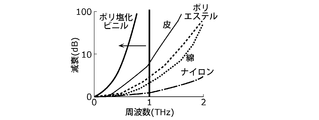
- FIG. 1 is a diagram showing the relationship between the attenuation factor and the frequency when an electromagnetic wave passes through a substance.
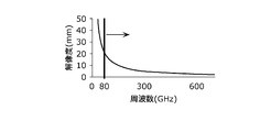
- FIG. 2 is a diagram showing the relationship between the frequency of electromagnetic waves and the resolution.
- FIG. 3 is a block diagram showing the configuration of the photographing apparatus according to the first embodiment.
- FIG. 4 is a schematic view showing the configuration of the light source according to the first embodiment.
- FIG. 5 is a schematic view showing a cross section of the detector according to the first embodiment receiving the reflected wave.
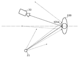
- FIG. 6 is a schematic view showing a cross section of a detector according to the first comparative example receiving a reflected wave.
- FIG. 7 is a schematic view showing how the photographing apparatus according to the first embodiment is installed.
- FIG. 1 is a diagram showing the relationship between the attenuation factor and the frequency when an electromagnetic wave passes through a substance.
- FIG. 2 is a diagram showing the relationship between the frequency of electromagnetic waves and the resolution.
- FIG. 3 is a block diagram showing the configuration of the
- FIG. 8 is a block diagram showing the configuration of the photographing apparatus according to the second embodiment.
- FIG. 9 is a schematic view showing a cross section of the detector according to the second embodiment receiving the reflected wave.
- FIG. 10 is a schematic view showing a cross section of the detector according to the second comparative example receiving the reflected wave.
- FIG. 11 is a schematic view showing a cross section of a state in which the photographing apparatus according to the second embodiment is installed.
- FIG. 12 is a flowchart of the image analysis process.
- FIG. 13 is a schematic view showing a part of the appearance of the photographing apparatus according to the modified example.
- the inventor has diligently studied a photographing device capable of detecting a dangerous object (for example, a knife) hidden under clothes or the like in a bag or the like.
- a dangerous object for example, a knife
- the inventor examined the relationship between the attenuation factor and frequency when electromagnetic waves are transmitted through substances that are materials such as clothes and bags.
- FIG. 1 is a diagram showing the relationship between the attenuation factor and the frequency when an electromagnetic wave passes through a substance.
- electromagnetic waves having a frequency of 1 THz or less can transmit most of the substances used as materials such as clothes and bags.
- the inventor examined the frequency that realizes the resolution that can capture the shape of a dangerous object.
- Equation 1 The relationship between the frequency (wavelength) of electromagnetic waves and the resolution (resolution) is expressed by (Equation 1) known as Abbe's equation.
- Equation 1 ⁇ is the resolution, ⁇ is the wavelength of the electromagnetic wave, NA is the numerical aperture of the lens, n is the refractive index of the medium between the object and the lens, and ⁇ is the maximum with respect to the optical axis of the light beam incident on the lens from the object. Indicates the angle.
- the entrance pupil diameter of the image pickup lens is D and the distance from the entrance pupil position of the image pickup lens to the object is d, d >> D, the approximation is obtained to obtain (Equation 2).
- the shape of a dangerous object such as a knife can be photographed by using an electromagnetic wave having a frequency of 80 GHz (0.08 THz) or higher.
- subterahertz which is an electromagnetic wave having a frequency of 0.08 THz or more and 1 THz or less, in order to perform photography capable of detecting dangerous substances hidden in a bag or the like under clothes or the like. We found that it is appropriate to use waves.
- sub-terahertz waves do not adversely affect the human body. Therefore, there is no problem from the viewpoint of safety to use the sub-terahertz wave as the electromagnetic wave radiated toward the human body.
- sub-terahertz waves are specularly reflected on the human body, metals, etc.
- a point light source here, sub-terahertz waves
- the shape of the human body, the shape of metallic dangerous objects such as blades, etc. must be photographed with high accuracy. Is difficult.
- the inventor examined the shape of the light source that radiates the sub-terahertz wave.
- the light source that emits the sub-terahertz wave is a surface light source
- the inventor can irradiate the object to be photographed with the sub-terahertz wave from various angles as compared with the case where the light source is a point light source. Since it is possible, it has been found that the shape of an object that mirror-reflects a sub-terahertz wave such as a human body or metal can be imaged more accurately than before.
- the inventor came up with the following imaging device based on the above findings.
- the photographing apparatus includes a first light source including a first radiation surface that radiates a sub-terahertz wave with respect to a measurement object, and a sub-terahertz wave radiated from the first radiation surface.
- a first detector including a first image sensor that receives a reflected wave from the measurement object.
- the above-mentioned photographing apparatus uses a sub-terahertz wave radiated from a first light source serving as a surface light source to perform photographing. Therefore, according to the above-mentioned photographing device, it is possible to photograph the shape of an object such as a human body or metal hidden under clothes or the like with higher accuracy than before.
- the first light source is a sub-terahertz wave radiated from the first radiation surface from one or more point light sources radiating a sub-terahertz wave and a sub-terahertz wave radiated from the one or more point light sources.
- the optical element may include a reflector that generates a sub-terahertz wave radiated from the first radiation surface by diffuse-reflecting the sub-terahertz wave radiated from the one or more point light sources. ..
- the optical element may include a diffuser plate that generates a sub-terahertz wave radiated from the first radiation surface by diffusing and transmitting the sub-terahertz wave radiated from the one or more point light sources.
- the first radiation surface may be a curved surface.
- the curved surface may include a part of the inner surface of the spheroidal surface.
- the spheroidal surface may be a spherical surface.
- the first radiation surface includes a part of the inner surface of the rotating elliptical surface
- the first light source is a point light source that emits a sub-terahertz wave and a sub-terahertz wave emitted from the point light source. It may include an optical element that generates a sub-terahertz wave radiated from the first radiation surface, and may be arranged at one of the two focal points of the rotating elliptical surface.
- a second light source including a second radiation surface that emits a sub-terahertz wave, and a second image sensor that receives a reflected wave of the sub-terahertz wave emitted from the second radiation surface.
- a second detector may be provided.
- the first image sensor outputs a first image based on the detected intensity of the sub-terahertz wave
- the second image sensor outputs a second image based on the detected intensity of the sub-terahertz wave.
- it may be provided with an image processing unit that comparatively brightly synthesizes the first image and the second image to generate a composite image and outputs the generated composite image.
- the image processing unit determines whether or not at least one of the first image and the second image contains an object having a predetermined feature, and the first image and the second image are described. When it is determined that at least one of the second image contains an object having the predetermined feature, a predetermined first detection signal is output, and the first image and the second image are output. If it is not determined that at least one of the images and the image contains the object having the predetermined feature, the composite image is generated, and the composite image further includes the object having the predetermined feature. When it is determined whether or not the composite image contains an object having the predetermined feature, a predetermined second detection signal may be output.
- the sub-terahertz wave may be an electromagnetic wave having a frequency of 0.08 THz or more and 1 THz or less.
- each of the embodiments shown here shows a specific example of the present disclosure. Therefore, the numerical values, shapes, components, arrangement and connection forms of the components, steps (processes), order of steps, etc. shown in the following embodiments are examples and do not limit the present disclosure. .. Further, each figure is a schematic view and is not necessarily exactly illustrated.
- the term plane means not only a plane that is exactly flat, but also a plane that is substantially flat.
- the term spheroidal surface means not only a surface that is exactly a spheroidal surface but also a surface that is substantially a spheroidal surface.
- the comprehensive or specific embodiment of the present disclosure may be realized by a recording medium such as a system, a method, an integrated circuit, a computer program or a computer-readable CD-ROM, and the system, the method, the integrated circuit, the computer. It may be realized by any combination of a program and a recording medium.
- FIG. 3 is a block diagram showing the configuration of the photographing apparatus 10 according to the first embodiment.
- the photographing apparatus 10 includes a light source 20, a detector 30, and an image processing unit 40.
- the light source 20 radiates a sub-terahertz wave to the object to be measured (here, the person 100).
- FIG. 4 is a schematic diagram showing the configuration of the light source 20.
- the light source 20 includes a point light source 21 and an optical element 23.
- the point light source 21 radiates a sub-terahertz wave radially in all directions around the point light source 21.
- the optical element 23 has a radiation surface 22 and generates a sub-terahertz wave radiated from the radiation surface 22 from the sub-terahertz wave radiated from the point light source 21.
- the radial surface 22 is a flat surface. Therefore, the optical element 23 functions as a surface light source that radiates a sub-terahertz wave from the plane radiation surface 22.
- the radiation surface of the sub-terahertz wave is a plane for convenience of explanation, but it may be an inner surface of a spheroid, an inner surface of a spherical surface, which will be described later, or an arbitrary curved surface.
- FIG. 5 is a schematic view showing a cross section of a light source 20 functioning as a surface light source that emits a sub-terahertz wave, and a detector 30 described later receiving a reflected wave from a measurement object.
- the optical element 23 is configured to include a diffuser plate 24, and the main plane on the front side thereof is a radiation surface 22.
- the diffuser plate 24 diffuses and transmits the sub-terahertz wave radiated from the point light source 21, thereby generating the sub-terahertz wave radiated from the radiation surface 22.
- the diffuser plate 24 has a flat plate shape parallel to the radiation surface 22 when viewed from a macro perspective. On the other hand, when viewed from a microscopic point of view, the diffuser plate 24 has minute undulations formed on the entire surface so that the transmitted sub-terahertz wave is diffused.
- the point light source 21 is arranged on the back side of the optical element 23.
- the sub-terahertz wave radiated from the point light source 21 penetrates into the inside of the optical element 23 from the main surface on the back side of the optical element 23 and reaches the diffuser plate 24.
- the sub-terahertz wave that has reached the diffuser plate 24 is diffused and transmitted through the diffuser plate 24.
- the sub-terahertz wave diffused and transmitted through the diffusion plate 24 propagates to the radiation surface 22 and is radiated to the outside from the radiation surface 22.
- the detector 30 includes an image sensor 31.
- the image sensor 31 converts an image of a sub-terahertz wave emitted from a subject into an electric signal according to its intensity. Then, the image sensor 31 generates an image based on the converted electric signal.
- imaging the fact that the image sensor 31 generates an image including an image of a subject is also referred to as “imaging”.
- the image sensor 31 Receives the reflected wave.
- the image sensor 31 receives the reflected wave from the region of the angle at which the mirror-reflected reflected wave is incident on the image sensor 31 among the body of the person 100 and the blade hidden by the person 100. Then, the image sensor 31 detects the intensity of the reflected wave to be received.
- the light source 20 functions as a surface light source that radiates a sub-terahertz wave from the radiation surface 22. Therefore, the light source 20 can irradiate the person 100 with sub-terahertz waves from various angles. Therefore, as shown in FIG. 5, the image sensor 31 reflects from a relatively wide range of the surface of the person 100, that is, the body of the person 100 and the surface of the blade hidden by the person 100. Can receive waves. Therefore, the photographing device 10 can image a relatively wide area 101 of the body of the person 100 and the surface of the blade hidden by the person 100.
- FIG. 6 shows a first image pickup device according to a first comparative example in which the optical element 23 is removed from the light source 20, that is, the first configuration in which the sub-terahertz wave radiated by the point light source 21 is radiated to the outside as it is. It is a schematic diagram which shows the cross section of the state which the detector 30 receives a reflected wave in the photographing apparatus which concerns on a comparative example.
- the photographing apparatus according to the first comparative example in the image sensor 31, the reflected wave reflected from the mirror surface of the body of the person 100 and the surface of the blade hidden by the person 100 is the image sensor 31. Only the reflected wave from the region 101a at an angle incident on the can be received. Therefore, the photographing apparatus according to the first comparative example can image only a relatively narrow range 101a of the body of the person 100 and the surface of the blade hidden by the person 100.
- the photographing device 10 according to the first embodiment can image the body of the person 100 and the shape of the blade hidden by the person 100 with higher accuracy than the photographing device according to the first comparative example.
- the detector 30 outputs the image generated by the image sensor 31 to the image processing unit 40.
- the image processing unit 40 When the image processing unit 40 receives an image from the detector 30, the image processing unit 40 outputs the received image to the outside, performs image processing on the received image, and outputs the result of the image processing to the outside.
- the image processing performed by the image processing unit 40 determines, for example, whether or not the image output from the detector 30 includes an object having a predetermined feature (for example, an object having the feature of a blade), and determines. When it is determined that an object having the characteristics of the above is included, the process may be a process of outputting a predetermined detection signal (for example, an alarm indicating that the object having the characteristics of the blade is being photographed).
- the image processing unit 40 includes, for example, a processor and a memory, and the processor may be realized by executing a program stored in the memory.
- the photographing device 10 having the above configuration is installed, for example, in a passage in an airport, near a ticket gate of a station, or the like.
- FIG. 7 is a schematic view showing how the photographing device 10 is installed in the passage in the airport.
- the photographing device 10 may be installed, for example, in which the optical element 23 and the detector 30 are embedded inside the wall of the crank-shaped passage 200 at the airport.
- the sub-terahertz wave radiated from the radiating surface 22 inside the wall passes through the wall and irradiates the person 100. Then, the reflected wave of the sub-terahertz wave reflected by the person 100 passes through the wall again and is incident on the detector 30. As a result, the photographing device 10 can photograph a dangerous object such as a knife hidden under clothes or the like by the person 100 passing through the passage 200.
- FIG. 8 is a block diagram showing the configuration of the photographing apparatus 10a according to the second embodiment.
- the light source 20 is changed to the first light source 20a and the second light source 20b from the photographing device 10 according to the first embodiment, and the detector 30 is the first detection.
- the device 30a and the second detector 30b are changed, and the image processing unit 40 is changed to the image processing unit 40a.
- the first light source 20a radiates a sub-terahertz wave to the object to be measured (here, the person 100).
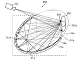
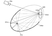
- FIG. 9 is a schematic view showing a cross section showing the configuration of the first light source 20a, how the first light source 20a functions as a surface light source, and how the first detector 30a, which will be described later, receives the reflected wave. ..
- the first light source 20a includes a point light source 21a and an optical element 23a.
- the point light source 21a radiates a sub-terahertz wave radially in all directions around the point light source 21a.
- the optical element 23a has a first radiation surface 22a, and generates a sub-terahertz wave radiated from the first radiation surface 22a from the sub-terahertz wave radiated from the point light source 21a.
- the first radial surface 22a is the inner surface of the spheroidal surface. Therefore, the optical element 23a functions as a surface light source that radiates a sub-terahertz wave from the first radiation surface 22a, which is the inner surface of the spheroidal surface.
- the optical element 23a is configured to include a reflector 24a, and the curved surface inside the optical element 23a is a first radiation surface 22a.
- the reflector 24a diffusely reflects the sub-terahertz wave radiated from the point light source 21a to generate the sub-terahertz wave radiated from the first radiation surface 22a. From a macroscopic point of view, the reflector 24a has a similar shape to the first radiation surface 22a, which is equal to or larger than the first radiation surface 22a, and the positions of the two focal points are the first radiation, respectively. It coincides with the positions of the two focal points on the surface 22a. On the other hand, when viewed from a microscopic point of view, the reflector 24a has minute undulations formed on the entire surface of the reflecting surface so that the reflected sub-terahertz wave is diffused.
- the point light source 21a is arranged at the focal point 301a of one of the two focal points of the first radiation surface 22a.
- the sub-terahertz wave radiated from the point light source 21a penetrates into the inside of the optical element 23a from the first radiation surface 22a and reaches the reflector 24a.
- the sub-terahertz wave that has reached the reflector 24a is diffusely reflected by the reflector 24a.
- the sub-terahertz wave diffusely reflected by the reflector 24a propagates to the first radiation surface 22a and is radiated to the outside from the first radiation surface 22a.
- the externally radiated sub-terahertz wave irradiates, for example, a person 100 in the vicinity of the other focal point 302a of the two focal points of the first radiation surface 22a.
- the second light source 20b in FIG. 8 has the same function as the first light source 20a, and its shape has a mirror image relationship with the first light source 20a. Therefore, the second light source 20b is replaced with the point light source 21b from the description of the first light source 20a, except that the shape of the second light source 20b has a mirror image relationship with the first light source 20a, and the optical element 23a Is replaced with an optical element 23b, a reflecting plate 24a is replaced with a reflecting plate 24b, one focal point 301a is replaced with one focal point 301b, and the other focal point 302a is replaced with the other focal point 302b.
- the first detector 30a includes the first image sensor 31a.
- the first detector 30a is the same as the detector 30 according to the first embodiment. That is, the first image sensor 31a is the same as the image sensor 31 according to the first embodiment.
- the second detector 30b is the same as the first detector 30a. Therefore, the second detector 30b will be described by replacing the first image sensor 31a with the second image sensor 31b from the description of the first detector 30a.
- the first light source 20a functions as a surface light source that radiates a sub-terahertz wave from the first radiation surface 22a. Therefore, the first light source 20a can irradiate the person 100 near the other focal point 302a with the sub-terahertz wave from various angles. Therefore, as shown in FIG. 9, the first image sensor 31a covers a relatively wide range of the surface of the person 100, that is, the body of the person 100 and the surface of the blade hidden by the person 100. Can receive the reflected wave of. Therefore, the photographing device 10a can image a relatively wide area 102 of the body of the person 100 and the surface of the blade hidden by the person 100.
- FIG. 10 shows that the first detector 30a receives the reflected wave in the photographing apparatus according to the second comparative example in which the reflector 24a is changed from the first light source 20a to the reflector 24aa.
- the reflector 24aa has the same shape as the reflector 24a when viewed from a macroscopic viewpoint, while the reflecting surface is mirror-reflected so that the reflected subterahertz wave is mirror-reflected when viewed from a microscopic viewpoint.
- the entire surface is formed smoothly. Therefore, all the sub-terahertz waves radiated from one focal point 301a and reflected by the reflector 24aa travel toward the other focal point 302a regardless of where the reflecting plate 24aa is reflected.
- the first image sensor 31a is the body of the person 100 near the other focal point 302a and the surface of the blade hidden by the person 100.
- the photographing apparatus according to the second comparative example can image only a relatively narrow range 102a of the body of the person 100 and the surface of the blade hidden by the person 100.
- the photographing device 10a according to the second embodiment can image the body of the person 100 and the shape of the blade hidden by the person 100 with higher accuracy than the photographing device according to the second comparative example.
- the first detector 30a and the second detector 30b transmit the first image and the second image generated by the first image sensor 31a and the second image sensor 31b to the image processing unit 40a, respectively. Output.
- the image processing unit 40a When the image processing unit 40a receives the first image and the second image from the first detector 30a and the second detector 30b, respectively, the image processing unit 40a sends the received first image and the second image to the outside. At the same time as outputting, image processing is performed on the received first image and second image, and the result of the image processing is output to the outside.
- the image processing performed by the image processing unit 40a is, for example, an object having predetermined characteristics in the first image and the second image output from the first detector 30a and the second detector 30b (for example, a blade).
- an object having the above-mentioned characteristics is included, and when it is determined that at least one of the first image and the second image contains an object having a predetermined characteristic.
- It may be a process of outputting a predetermined detection signal (for example, an alarm indicating that an object having the characteristics of a blade is being photographed).
- the image processing performed by the image processing unit 40a further determines that at least one of the first image and the second image contains an object having a predetermined feature, the first image.
- the image processing unit 40a may be realized by, for example, including a processor and a memory, and the processor executes a program stored in the memory.
- the photographing device 10a having the above configuration is installed, for example, in the passage in the airport or near the ticket gate of the station.
- FIG. 11 is a schematic view showing a cross section of the photographing device 10a installed in the passage near the ticket gate of the station.
- the photographing device 10a may be installed, for example, in which the optical element 23a and the optical element 23b are embedded inside the wall of the passage 400 near the ticket gate of the station. More specifically, the photographing apparatus 10a is installed, for example, by embedding the optical element 23a inside the wall 401a which is one side wall of the passage 400, and the optical element 23b is installed in the wall 401b which is the other side wall of the passage 400. It may be embedded and installed inside the. As described above, in the photographing apparatus 10a, the first light source 20a and the second light source 20b may be installed with the passage 400 interposed therebetween, and further, the first detector 30a and the second detector 30b may be installed. And may be installed across the passage 400.
- the first detector 30a is a reflected wave of the sub-terahertz wave emitted from the first radiation surface 22a and the second radiation surface 22b by the measurement object (here, the person 100) on the passage 400.
- the intensity of the subterahertz wave is detected by the first image sensor 31a
- the second detector 30b is the object to be measured on the passage 400 of the sub-terahertz wave emitted from the first radiation surface 22a and the second radiation surface 22b.
- the intensity of the reflected wave (here, the person 100) is detected by the second image sensor 31b.
- the optical element 23a and the optical element 23b may be installed so that the other focal point 302a of the optical element 23a and the other focal point 302b of the optical element 23b substantially coincide with each other on the center line of the passage 400.
- the sub-terahertz wave radiated from the point light source 21a and the sub-terahertz wave radiated from the point light source 21b are placed in a region near the other focal point 302a and the other focal point 302b (hereinafter,). , Also referred to as the "focus area”) can be irradiated from various angles. Therefore, as shown in FIG.
- the first image sensor 31a and the second image sensor 31b included in the first detector 30a and the second detector 30b are the person 100 walking in the focal region.
- the reflected wave can be received from a relatively wide range of the surface of the person 100, that is, the body of the person 100 and the surface of the blade hidden by the person 100. Therefore, the photographing device 10a can image a relatively wide area 103 of the body of the person 100 and the surface of the blade hidden by the person 100.
- the first image sensor 31a and the second image sensor 31b included in the first detector 30a and the second detector 30b each receive reflected waves from the region 103 at different angles. To do. Therefore, the photographing device 10a can image the body of the person 100 and the blade hidden by the person 100, which are the same subjects, from different angles.
- the photographing device 10a performs image analysis processing as an example.
- the photographing device 10a captures the first image and the second image, and based on the captured first image and the second image, an object having the characteristics of a blade is photographed. This is a process of outputting a detection signal, which is an alarm indicating that the image is running.
- FIG. 12 is a flowchart of the image analysis process performed by the photographing apparatus 10a.
- the image analysis process is started when a person invades the focal area.
- the photographing device 10a detects that the person has invaded the focal area.
- the photographing device 10a detects that a person has invaded the focal area by receiving, for example, a signal indicating that the person has invaded the focal area from an external sensor that detects that the person has invaded the focal area. You may.
- the first light source 20a and the second light source 20b radiate a sub-terahertz wave at the same timing in synchronization with each other (step S100). Further, the first detector 30a and the second detector 30b entered the focal region at the timing when the first light source 20a and the second light source 20b emit the sub-terahertz wave in synchronization with each other. An image of a person is taken (step S110). Then, the first detector 30a and the second detector 30b output the first image and the second image to the image processing unit 40a, respectively.
- the image processing unit 40a receives the output first image and the second image, and receives the first image and the second image. Is output to the outside (step S120). Then, the image processing unit 40a determines whether or not at least one of the first image and the second image includes an object having the characteristic of the blade, which is a predetermined characteristic (step S130).
- step S130 when it is not determined that at least one of the first image and the second image contains an object having a predetermined feature (step S130: No), the image processing unit 40a , The first image and the second image are comparatively brightly combined to generate a composite image, and the generated composite image is output to the outside (step S140). Then, the image processing unit 40a determines whether or not the generated composite image includes an object having the characteristics of the blade, which is a predetermined characteristic (step S150).
- step S130 when it is determined that at least one of the first image and the second image contains an object having a predetermined feature (step S130: Yes), and in the process of step S150.
- step S150: Yes the image processing unit 40a gives an alarm indicating that the object having the feature of the blade is being photographed.
- a certain detection signal is output to the outside (step S160).
- step S160 When the process of step S160 is completed, and when it is not determined in the process of step S150 that the composite image contains an object having a predetermined feature (step S150: No), the photographing device 10a captures the image. End the analysis process.
- the photographing apparatus 10a includes a first light source 20a including an optical element 23a having a first radiating surface 22a which is an inner surface of a spheroid surface, and a second light source 20a which is an inner surface of the spheroidal surface. It has been described that the configuration includes a second light source 20b including an optical element 23b having a radiation surface 22b of the above.
- the photographing apparatus according to the modified example according to another example of the present disclosure is the inner surface of the rotating ellipsoidal surface instead of the optical element 23a from the photographing apparatus 10a according to the second embodiment.
- the first light source according to the modified example in which the shape of the radial surface 22a of 1 is changed to the inner surface of a spherical surface is provided, and instead of the optical element 23b, the shape of the second radial surface 22b, which is the inner surface of the rotating ellipsoidal surface, is spherical. It may be modified and configured to include a second light source according to the modified example on the inner surface of the.
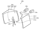
- FIG. 13 is a schematic view showing a part of the appearance of the photographing apparatus according to the modified example.
- the first light source 20c according to the modified example includes a point light source 21a and an optical element 23c having a first radiation surface 22c which is an inner surface of a spherical surface. Consists of.
- the point light source 21a is arranged near the center of the spherical surface.
- the second light source 20d according to the modified example includes a point light source 21b and an optical element 23d having a second radiation surface 22d which is an inner surface of a spherical surface.
- the point light source 21b is arranged near the center of the spherical surface.
- the optical element 23 has been described as being configured to include the diffuser plate 24.
- the optical element 23 may be the diffuser plate 24 itself. In this case, the surface of the diffusion plate 24 becomes the radiation surface 22.
- the optical element 23a and the optical element 23b have been described as including the reflector 24a and the reflector 24b, respectively.
- the optical element 23a and the optical element 23b may be the reflector 24a itself and the reflector 24b itself, respectively.
- the reflective surface of the reflector 24a and the reflective surface of the reflector 24b become the first radiation surface 22a and the second radiation surface 22b, respectively.
- the light source 20 includes one point light source 21.
- the number of point light sources included in the light source 20 is not necessarily limited to one, and may be plural.
- the optical element 23 generates a sub-terahertz wave radiated from the radiation surface 22 from the sub-terahertz wave radiated from these a plurality of point light sources.
- the first light source 20a and the second light source 20b include one point light source 21a and one point light source 21b, respectively.
- the number of point light sources included in the first light source 20a and the second light source 20b is not necessarily limited to one, and may be plural.
- the optical element 23a and the optical element 23b generate a sub-terahertz wave radiated from the first radiation surface 22a and the second radiation surface 22b from the sub-terahertz waves radiated from the plurality of point light sources, respectively. It will be.
- One aspect of the present disclosure may be not only the photographing apparatus according to the first and second embodiments, but also an imaging method in which a characteristic component included in the photographing apparatus is a step.
- One aspect of the present disclosure may be a program that causes a computer to perform each characteristic step included in the photographing method.
- one aspect of the present disclosure may be a computer-readable non-temporary recording medium on which such a program is recorded.
- This disclosure can be widely used in a photographing device for photographing an object.
- Imaging device 20 Light source 20a, 20c First light source 20b, 20d Second light source 21, 21a, 21b Point light source 22 Radiation surface 22a, 22c First radiation surface 22b, 22d Second radiation surface 23, 23a , 23b, 23c, 23d Optical element 24 Diffusing plate 24a, 24aa, 24b Reflector 30 Detector 30a First detector 30b Second detector 31 Image sensor 31a First image sensor 31b Second image sensor 40, 40a Image processing unit 100 People 101, 101a, 102, 102a, 103 Area 200, 400 Passage 301a, 301b One light source 302a, 302b The other light source 401a, 401b Wall
Landscapes
- Physics & Mathematics (AREA)
- Health & Medical Sciences (AREA)
- Spectroscopy & Molecular Physics (AREA)
- General Physics & Mathematics (AREA)
- Life Sciences & Earth Sciences (AREA)
- Chemical & Material Sciences (AREA)
- Analytical Chemistry (AREA)
- Biochemistry (AREA)
- General Health & Medical Sciences (AREA)
- Immunology (AREA)
- Pathology (AREA)
- Toxicology (AREA)
- Signal Processing (AREA)
- Multimedia (AREA)
- Engineering & Computer Science (AREA)
- Investigating Or Analysing Materials By Optical Means (AREA)
Priority Applications (4)
| Application Number | Priority Date | Filing Date | Title |
|---|---|---|---|
| JP2021550333A JP7561340B2 (ja) | 2019-10-09 | 2020-06-24 | 撮影装置 |
| CN202080062837.2A CN114402191A (zh) | 2019-10-09 | 2020-06-24 | 摄影装置 |
| EP20873366.7A EP4043865A4 (en) | 2019-10-09 | 2020-06-24 | PHOTOGRAPHY DEVICE |
| US17/707,331 US12279026B2 (en) | 2019-10-09 | 2022-03-29 | Imaging device |
Applications Claiming Priority (2)
| Application Number | Priority Date | Filing Date | Title |
|---|---|---|---|
| JP2019-185627 | 2019-10-09 | ||
| JP2019185627 | 2019-10-09 |
Related Child Applications (1)
| Application Number | Title | Priority Date | Filing Date |
|---|---|---|---|
| US17/707,331 Continuation US12279026B2 (en) | 2019-10-09 | 2022-03-29 | Imaging device |
Publications (1)
| Publication Number | Publication Date |
|---|---|
| WO2021070428A1 true WO2021070428A1 (ja) | 2021-04-15 |
Family
ID=75437083
Family Applications (1)
| Application Number | Title | Priority Date | Filing Date |
|---|---|---|---|
| PCT/JP2020/024787 Ceased WO2021070428A1 (ja) | 2019-10-09 | 2020-06-24 | 撮影装置 |
Country Status (5)
| Country | Link |
|---|---|
| US (1) | US12279026B2 (https=) |
| EP (1) | EP4043865A4 (https=) |
| JP (1) | JP7561340B2 (https=) |
| CN (1) | CN114402191A (https=) |
| WO (1) | WO2021070428A1 (https=) |
Cited By (4)
| Publication number | Priority date | Publication date | Assignee | Title |
|---|---|---|---|---|
| WO2022234685A1 (ja) * | 2021-05-06 | 2022-11-10 | パナソニックIpマネジメント株式会社 | 拡散部材 |
| US12259320B2 (en) | 2020-03-18 | 2025-03-25 | Panasonic Intellectual Property Management Co., Ltd. | Imaging device |
| US12306292B2 (en) | 2020-06-19 | 2025-05-20 | Panasonic Intellectual Property Management Co., Ltd. | Imaging apparatus including sub-terahertz wave reflective member |
| US12366651B2 (en) | 2020-06-19 | 2025-07-22 | Panasonic Intellectual Property Management Co., Ltd. | Imaging apparatus |
Families Citing this family (2)
| Publication number | Priority date | Publication date | Assignee | Title |
|---|---|---|---|---|
| WO2021070428A1 (ja) * | 2019-10-09 | 2021-04-15 | パナソニックIpマネジメント株式会社 | 撮影装置 |
| WO2022219833A1 (ja) * | 2021-04-15 | 2022-10-20 | パナソニックIpマネジメント株式会社 | 撮影装置 |
Citations (16)
| Publication number | Priority date | Publication date | Assignee | Title |
|---|---|---|---|---|
| JP2007218661A (ja) * | 2006-02-15 | 2007-08-30 | Canon Inc | 対象物の情報を検出する検出装置 |
| US20130015354A1 (en) * | 2010-03-29 | 2013-01-17 | Inspection Technologies Limited | Inspection apparatus and method |
| US8835849B1 (en) | 2010-02-10 | 2014-09-16 | Mvt Equity Llc | Method and apparatus for detection of concealed objects in passive thermal images using environment control |
| JP2015195562A (ja) * | 2014-03-20 | 2015-11-05 | 村上 幹次 | 送信信号処理装置及び方法、受信信号処理装置 |
| US20150378449A1 (en) * | 2008-06-27 | 2015-12-31 | Texas Instruments Incorporated | Imaging input/output with shared spatial modulator |
| JP2017009296A (ja) * | 2015-06-16 | 2017-01-12 | キヤノン株式会社 | 電磁波伝搬装置及び情報取得装置 |
| WO2017175770A1 (ja) * | 2016-04-05 | 2017-10-12 | 株式会社分光計測 | 生体組織力学的物性量観測方法および生体組織力学的物性量観測装置 |
| WO2018097035A1 (ja) * | 2016-11-28 | 2018-05-31 | キヤノン株式会社 | 画像取得装置、これを用いた画像取得方法及び照射装置 |
| JP2018110399A (ja) * | 2016-12-30 | 2018-07-12 | アクシス アーベー | 方法、装置、およびカメラ |
| EP3363357A1 (en) * | 2017-02-20 | 2018-08-22 | Koninklijke Philips N.V. | Contactless skin surface conductivity detector |
| JP2018201156A (ja) * | 2017-05-29 | 2018-12-20 | キヤノン株式会社 | 画像処理装置および画像処理方法 |
| WO2019059120A1 (ja) * | 2017-09-22 | 2019-03-28 | 日本電気株式会社 | 情報処理装置、情報処理システム、情報処理方法、及び、記録媒体 |
| US20190117109A1 (en) * | 2016-04-15 | 2019-04-25 | The Regents Of The University Of California | THz Sensing of Corneal Tissue Water Content |
| US20190120756A1 (en) * | 2017-10-25 | 2019-04-25 | Electronics And Telecommunications Research Institute | Terahertz reflection imaging system using rotating polyhedral mirror and telecentric f-theta lens |
| US10332089B1 (en) * | 2015-03-31 | 2019-06-25 | Amazon Technologies, Inc. | Data synchronization system |
| JP2019526812A (ja) * | 2016-07-17 | 2019-09-19 | ビー.ジー.ネゲブ テクノロジーズ アンド アプリケーションズ リミテッド, アット ベン‐グリオン ユニバーシティー | 撮像および通信のためのアップコンバージョンシステム |
Family Cites Families (45)
| Publication number | Priority date | Publication date | Assignee | Title |
|---|---|---|---|---|
| US5047783A (en) * | 1987-11-06 | 1991-09-10 | Millitech Corporation | Millimeter-wave imaging system |
| GB9700966D0 (en) * | 1997-01-17 | 1997-03-05 | Secr Defence | Millimetre wave imaging apparatus |
| US6777684B1 (en) * | 1999-08-23 | 2004-08-17 | Rose Research L.L.C. | Systems and methods for millimeter and sub-millimeter wave imaging |
| US7119740B2 (en) * | 2003-12-05 | 2006-10-10 | Safeview, Inc. | Millimeter-wave active imaging system with modular array |
| US7105820B2 (en) * | 2004-01-16 | 2006-09-12 | New Jersey Institute Of Technology | Terahertz imaging for near field objects |
| JP4547186B2 (ja) * | 2004-04-16 | 2010-09-22 | 潤一 西澤 | 殺菌装置 |
| GB0417394D0 (en) * | 2004-08-04 | 2004-09-08 | Council Cent Lab Res Councils | Scanning imaging device |
| US6965340B1 (en) * | 2004-11-24 | 2005-11-15 | Agilent Technologies, Inc. | System and method for security inspection using microwave imaging |
| WO2006131910A2 (en) * | 2005-06-08 | 2006-12-14 | Electro-Optics Research & Development Ltd. | Active millimeter wave imaging system and method |
| DE102006012715B4 (de) * | 2006-03-17 | 2008-04-24 | Technische Universität Braunschweig Carolo-Wilhelmina | Vorrichtung zum Abbilden eines Objektes mit einer Strahlungsquelle zur Emission einer Terahertzstrahlung |
| IL176411A0 (en) * | 2006-06-19 | 2007-07-04 | Ariel University Res And Dev C | Hand-held device and method for detecting concealed weapons and hidden objects |
| US20120120385A1 (en) * | 2006-06-27 | 2012-05-17 | Jian-Ping Jiang | Pathogen detection by simultaneous size/fluorescence measurement |
| US7642949B2 (en) * | 2006-08-03 | 2010-01-05 | Lockheed Martin Corporation | Illumination source for millimeter wave imaging |
| RU2442187C2 (ru) * | 2007-02-21 | 2012-02-10 | Смитс Хайманн Гмбх | Устройство для формирования изображения проверяемых объектов посредством электромагнитных волн, прежде всего, для контроля пассажиров на наличие подозрительных предметов |
| US7873182B2 (en) * | 2007-08-08 | 2011-01-18 | Brijot Imaging Systems, Inc. | Multiple camera imaging method and system for detecting concealed objects |
| US8628976B2 (en) * | 2007-12-03 | 2014-01-14 | Azbil BioVigilant, Inc. | Method for the detection of biologic particle contamination |
| EP2235736B1 (en) * | 2007-12-13 | 2015-04-01 | Azbil Corporation | Pathogen detection by simultaneous size/fluorescence measurement |
| US20140300502A9 (en) * | 2007-12-18 | 2014-10-09 | Brijot Imaging Systems, Inc. | Millimeter Wave Energy Sensing Wand and Method |
| US8021008B2 (en) * | 2008-05-27 | 2011-09-20 | Abl Ip Holding Llc | Solid state lighting using quantum dots in a liquid |
| FI20095065A0 (fi) * | 2009-01-26 | 2009-01-26 | Wallac Oy | Yhdistetty linssi ja heijastin sekä sitä käyttävä optinen laite |
| JP5363199B2 (ja) * | 2009-06-04 | 2013-12-11 | 日本分光株式会社 | 顕微全反射測定装置 |
| US8350223B2 (en) * | 2009-07-31 | 2013-01-08 | Raytheon Company | Quantum dot based radiation source and radiometric calibrator using the same |
| GB0916300D0 (en) * | 2009-09-17 | 2009-10-28 | Univ Manchester Metropolitan | Remote detection of bladed objects |
| CN101793953B (zh) * | 2010-02-09 | 2012-10-03 | 中国科学院上海微系统与信息技术研究所 | 用于室内毫米波成像安检系统的辅助源照射装置 |
| US20120075477A1 (en) * | 2010-09-29 | 2012-03-29 | Robert Patrick Daly | Handheld terahertz wave imaging system |
| EP2505540A1 (de) * | 2011-03-28 | 2012-10-03 | Inventio AG | Zugangsüberwachungsvorrichtung mit mindestens einer Videoeinheit |
| WO2012145741A2 (en) * | 2011-04-22 | 2012-10-26 | The University Of Memphis Reasearch Foundation | Spatially-selective disks, submillimeter imaging devices, methods of submillimeter imaging profiling scanners, spectrometry devices, and methods of spectrometry |
| US20120273681A1 (en) * | 2011-04-26 | 2012-11-01 | Zomega Terahertz Corporation | Terahertz spectrometer |
| CN103477196B (zh) * | 2011-10-13 | 2016-06-22 | 大塚电子株式会社 | 光学测量系统和光学测量方法 |
| DE102012204174B4 (de) * | 2012-03-16 | 2022-03-10 | Rohde & Schwarz GmbH & Co. Kommanditgesellschaft | Verfahren, System und Kalibrierobjekt zur automatischen Kalibrierung einer bildgebenden Antennenanordnung |
| JP5962167B2 (ja) * | 2012-04-19 | 2016-08-03 | セイコーエプソン株式会社 | 検出回路、センサーデバイス及び電子機器 |
| KR101411428B1 (ko) * | 2012-07-12 | 2014-06-24 | 한국과학기술원 | 집광식 휴대용 형광 검출 시스템 |
| EP3298432B1 (en) * | 2015-05-18 | 2019-07-10 | Lasermotive, Inc. | Multi-layered safety system |
| WO2017024074A1 (en) * | 2015-08-03 | 2017-02-09 | Phase Sensitive Innovations, Inc. | Distributed array for direction and frequency finding |
| US10330610B2 (en) * | 2015-09-16 | 2019-06-25 | Massachusetts Institute Of Technology | Methods and apparatus for imaging of near-field objects with microwave or terahertz radiation |
| US11217009B2 (en) * | 2015-11-30 | 2022-01-04 | Photopotech LLC | Methods for collecting and processing image information to produce digital assets |
| CN105675131B (zh) * | 2016-01-13 | 2018-03-27 | 南京邮电大学 | 基于衍射效应的太赫兹波谱测量装置及其测量方法 |
| IL248615B (en) * | 2016-10-30 | 2020-05-31 | Rohde & Schwarz | Method and system for security inspection using a detector gate |
| KR102450625B1 (ko) * | 2017-08-31 | 2022-10-07 | 서울바이오시스 주식회사 | 검출기 |
| WO2019156977A1 (en) * | 2018-02-06 | 2019-08-15 | Overhead Door Corporation | Secure exit lane door |
| CN109581530B (zh) * | 2018-12-28 | 2025-02-18 | 同方威视技术股份有限公司 | 便携式太赫兹安检设备 |
| US11553969B1 (en) * | 2019-02-14 | 2023-01-17 | Onpoint Medical, Inc. | System for computation of object coordinates accounting for movement of a surgical site for spinal and other procedures |
| JP2020204513A (ja) * | 2019-06-17 | 2020-12-24 | 株式会社東芝 | システム及び検査方法 |
| WO2021070428A1 (ja) * | 2019-10-09 | 2021-04-15 | パナソニックIpマネジメント株式会社 | 撮影装置 |
| US11297255B1 (en) * | 2020-09-18 | 2022-04-05 | Raytheon Company | On-board light source calibration |
-
2020
- 2020-06-24 WO PCT/JP2020/024787 patent/WO2021070428A1/ja not_active Ceased
- 2020-06-24 EP EP20873366.7A patent/EP4043865A4/en not_active Withdrawn
- 2020-06-24 JP JP2021550333A patent/JP7561340B2/ja active Active
- 2020-06-24 CN CN202080062837.2A patent/CN114402191A/zh active Pending
-
2022
- 2022-03-29 US US17/707,331 patent/US12279026B2/en active Active
Patent Citations (16)
| Publication number | Priority date | Publication date | Assignee | Title |
|---|---|---|---|---|
| JP2007218661A (ja) * | 2006-02-15 | 2007-08-30 | Canon Inc | 対象物の情報を検出する検出装置 |
| US20150378449A1 (en) * | 2008-06-27 | 2015-12-31 | Texas Instruments Incorporated | Imaging input/output with shared spatial modulator |
| US8835849B1 (en) | 2010-02-10 | 2014-09-16 | Mvt Equity Llc | Method and apparatus for detection of concealed objects in passive thermal images using environment control |
| US20130015354A1 (en) * | 2010-03-29 | 2013-01-17 | Inspection Technologies Limited | Inspection apparatus and method |
| JP2015195562A (ja) * | 2014-03-20 | 2015-11-05 | 村上 幹次 | 送信信号処理装置及び方法、受信信号処理装置 |
| US10332089B1 (en) * | 2015-03-31 | 2019-06-25 | Amazon Technologies, Inc. | Data synchronization system |
| JP2017009296A (ja) * | 2015-06-16 | 2017-01-12 | キヤノン株式会社 | 電磁波伝搬装置及び情報取得装置 |
| WO2017175770A1 (ja) * | 2016-04-05 | 2017-10-12 | 株式会社分光計測 | 生体組織力学的物性量観測方法および生体組織力学的物性量観測装置 |
| US20190117109A1 (en) * | 2016-04-15 | 2019-04-25 | The Regents Of The University Of California | THz Sensing of Corneal Tissue Water Content |
| JP2019526812A (ja) * | 2016-07-17 | 2019-09-19 | ビー.ジー.ネゲブ テクノロジーズ アンド アプリケーションズ リミテッド, アット ベン‐グリオン ユニバーシティー | 撮像および通信のためのアップコンバージョンシステム |
| WO2018097035A1 (ja) * | 2016-11-28 | 2018-05-31 | キヤノン株式会社 | 画像取得装置、これを用いた画像取得方法及び照射装置 |
| JP2018110399A (ja) * | 2016-12-30 | 2018-07-12 | アクシス アーベー | 方法、装置、およびカメラ |
| EP3363357A1 (en) * | 2017-02-20 | 2018-08-22 | Koninklijke Philips N.V. | Contactless skin surface conductivity detector |
| JP2018201156A (ja) * | 2017-05-29 | 2018-12-20 | キヤノン株式会社 | 画像処理装置および画像処理方法 |
| WO2019059120A1 (ja) * | 2017-09-22 | 2019-03-28 | 日本電気株式会社 | 情報処理装置、情報処理システム、情報処理方法、及び、記録媒体 |
| US20190120756A1 (en) * | 2017-10-25 | 2019-04-25 | Electronics And Telecommunications Research Institute | Terahertz reflection imaging system using rotating polyhedral mirror and telecentric f-theta lens |
Non-Patent Citations (1)
| Title |
|---|
| See also references of EP4043865A4 |
Cited By (4)
| Publication number | Priority date | Publication date | Assignee | Title |
|---|---|---|---|---|
| US12259320B2 (en) | 2020-03-18 | 2025-03-25 | Panasonic Intellectual Property Management Co., Ltd. | Imaging device |
| US12306292B2 (en) | 2020-06-19 | 2025-05-20 | Panasonic Intellectual Property Management Co., Ltd. | Imaging apparatus including sub-terahertz wave reflective member |
| US12366651B2 (en) | 2020-06-19 | 2025-07-22 | Panasonic Intellectual Property Management Co., Ltd. | Imaging apparatus |
| WO2022234685A1 (ja) * | 2021-05-06 | 2022-11-10 | パナソニックIpマネジメント株式会社 | 拡散部材 |
Also Published As
| Publication number | Publication date |
|---|---|
| EP4043865A1 (en) | 2022-08-17 |
| JP7561340B2 (ja) | 2024-10-04 |
| CN114402191A (zh) | 2022-04-26 |
| JPWO2021070428A1 (https=) | 2021-04-15 |
| US12279026B2 (en) | 2025-04-15 |
| US20220224845A1 (en) | 2022-07-14 |
| EP4043865A4 (en) | 2022-11-23 |
Similar Documents
| Publication | Publication Date | Title |
|---|---|---|
| WO2021070428A1 (ja) | 撮影装置 | |
| EP3904917B1 (en) | Portable terahertz security check apparatus | |
| RU2510036C2 (ru) | Адаптивная система обнаружения | |
| JP7455611B2 (ja) | 処理システム | |
| CN106353834B (zh) | 一种太赫兹成像系统及太赫兹安检装置 | |
| JP5328812B2 (ja) | 物体を検出するための補助照明のための装置及び方法 | |
| US20110178401A1 (en) | Biological information acquisition apparatus | |
| JP2021047377A (ja) | 撮像装置、撮像装置の制御方法、プログラム | |
| JPWO2021070428A5 (https=) | ||
| JP6276736B2 (ja) | 物質識別装置 | |
| WO2016022757A1 (en) | Single channel terahertz endoscopy | |
| US11621788B2 (en) | Terahertz wave camera system, entry/exit management apparatus, and method for controlling terahertz wave camera system | |
| US20210196135A1 (en) | Blood vessel detection device and method therefor | |
| WO2017020402A1 (zh) | 一种邮件检测装置和方法 | |
| US20090002718A1 (en) | Optical Measurement Device | |
| WO2021186822A1 (ja) | 撮影装置 | |
| JP7614809B2 (ja) | テラヘルツ波カメラシステム、およびテラヘルツ波カメラシステムの制御方法 | |
| KR20240043339A (ko) | 은닉된 위험물을 탐지하는 보안검색기 | |
| WO2019226261A2 (en) | Method and system for multispectral imaging | |
| JP2023063919A (ja) | 撮像システム、テラヘルツ撮像装置、テラヘルツ撮像装置の制御方法、プログラム、および記憶媒体 | |
| JP7786810B2 (ja) | 撮像装置、撮像方法、及びコンピュータプログラム | |
| RU2220454C1 (ru) | Ручной обнаружитель предметов, скрытых под одеждой людей | |
| JP7603240B2 (ja) | 撮影装置 | |
| JP2014139531A (ja) | 赤外線波長測定による距離検出方法 | |
| CN118377058A (zh) | 便携式电磁波安检设备及安全检测方法 |
Legal Events
| Date | Code | Title | Description |
|---|---|---|---|
| 121 | Ep: the epo has been informed by wipo that ep was designated in this application |
Ref document number: 20873366 Country of ref document: EP Kind code of ref document: A1 |
|
| ENP | Entry into the national phase |
Ref document number: 2021550333 Country of ref document: JP Kind code of ref document: A |
|
| NENP | Non-entry into the national phase |
Ref country code: DE |
|
| ENP | Entry into the national phase |
Ref document number: 2020873366 Country of ref document: EP Effective date: 20220509 |