WO2021070428A1 - Photography device - Google Patents
Photography device Download PDFInfo
- Publication number
- WO2021070428A1 WO2021070428A1 PCT/JP2020/024787 JP2020024787W WO2021070428A1 WO 2021070428 A1 WO2021070428 A1 WO 2021070428A1 JP 2020024787 W JP2020024787 W JP 2020024787W WO 2021070428 A1 WO2021070428 A1 WO 2021070428A1
- Authority
- WO
- WIPO (PCT)
- Prior art keywords
- image
- sub
- terahertz wave
- light source
- radiation surface
- Prior art date
Links
- 230000005855 radiation Effects 0.000 claims abstract description 67
- 238000005259 measurement Methods 0.000 claims abstract description 14
- 230000003287 optical effect Effects 0.000 claims description 50
- 239000002131 composite material Substances 0.000 claims description 18
- 238000003384 imaging method Methods 0.000 claims description 12
- 238000001514 detection method Methods 0.000 claims description 10
- 238000000034 method Methods 0.000 description 19
- 230000000052 comparative effect Effects 0.000 description 11
- 238000010586 diagram Methods 0.000 description 10
- 239000002184 metal Substances 0.000 description 7
- 229910052751 metal Inorganic materials 0.000 description 7
- 230000006870 function Effects 0.000 description 6
- 239000000126 substance Substances 0.000 description 6
- 238000010191 image analysis Methods 0.000 description 5
- 238000009792 diffusion process Methods 0.000 description 2
- 239000000463 material Substances 0.000 description 2
- 210000001747 pupil Anatomy 0.000 description 2
- 0 CC(C)C(C1(C2)C(C)C1)C2(CN)*(CN)N Chemical compound CC(C)C(C1(C2)C(C)C1)C2(CN)*(CN)N 0.000 description 1
- IQULLIFEBOGYKR-UHFFFAOYSA-N CC1(C)C2C(CC3)(CC4)C3C4C(C3)C2C3C1 Chemical compound CC1(C)C2C(CC3)(CC4)C3C4C(C3)C2C3C1 IQULLIFEBOGYKR-UHFFFAOYSA-N 0.000 description 1
- DQGVFPVNWKSFEB-UHFFFAOYSA-N OC1(CC2C3)C22C3CC(CC3)(C4)CCCC34C12 Chemical compound OC1(CC2C3)C22C3CC(CC3)(C4)CCCC34C12 DQGVFPVNWKSFEB-UHFFFAOYSA-N 0.000 description 1
- 230000002411 adverse Effects 0.000 description 1
- 238000004458 analytical method Methods 0.000 description 1
- 238000004590 computer program Methods 0.000 description 1
- 150000002739 metals Chemical class 0.000 description 1
- 238000012986 modification Methods 0.000 description 1
- 230000004048 modification Effects 0.000 description 1
Images


Classifications
-
- G—PHYSICS
- G01—MEASURING; TESTING
- G01N—INVESTIGATING OR ANALYSING MATERIALS BY DETERMINING THEIR CHEMICAL OR PHYSICAL PROPERTIES
- G01N21/00—Investigating or analysing materials by the use of optical means, i.e. using sub-millimetre waves, infrared, visible or ultraviolet light
- G01N21/17—Systems in which incident light is modified in accordance with the properties of the material investigated
- G01N21/25—Colour; Spectral properties, i.e. comparison of effect of material on the light at two or more different wavelengths or wavelength bands
- G01N21/31—Investigating relative effect of material at wavelengths characteristic of specific elements or molecules, e.g. atomic absorption spectrometry
- G01N21/35—Investigating relative effect of material at wavelengths characteristic of specific elements or molecules, e.g. atomic absorption spectrometry using infrared light
- G01N21/3581—Investigating relative effect of material at wavelengths characteristic of specific elements or molecules, e.g. atomic absorption spectrometry using infrared light using far infrared light; using Terahertz radiation
-
- H—ELECTRICITY
- H04—ELECTRIC COMMUNICATION TECHNIQUE
- H04N—PICTORIAL COMMUNICATION, e.g. TELEVISION
- H04N23/00—Cameras or camera modules comprising electronic image sensors; Control thereof
- H04N23/10—Cameras or camera modules comprising electronic image sensors; Control thereof for generating image signals from different wavelengths
- H04N23/11—Cameras or camera modules comprising electronic image sensors; Control thereof for generating image signals from different wavelengths for generating image signals from visible and infrared light wavelengths
-
- G—PHYSICS
- G01—MEASURING; TESTING
- G01N—INVESTIGATING OR ANALYSING MATERIALS BY DETERMINING THEIR CHEMICAL OR PHYSICAL PROPERTIES
- G01N21/00—Investigating or analysing materials by the use of optical means, i.e. using sub-millimetre waves, infrared, visible or ultraviolet light
- G01N21/17—Systems in which incident light is modified in accordance with the properties of the material investigated
- G01N21/55—Specular reflectivity
-
- G—PHYSICS
- G01—MEASURING; TESTING
- G01N—INVESTIGATING OR ANALYSING MATERIALS BY DETERMINING THEIR CHEMICAL OR PHYSICAL PROPERTIES
- G01N21/00—Investigating or analysing materials by the use of optical means, i.e. using sub-millimetre waves, infrared, visible or ultraviolet light
- G01N21/17—Systems in which incident light is modified in accordance with the properties of the material investigated
- G01N2021/1765—Method using an image detector and processing of image signal
Definitions
- Patent Document 1 a photographing device for photographing an object hidden under clothes or the like and not directly visible is known (see, for example, Patent Document 1).
- a point light source that radiates an electromagnetic wave transmitted through clothes or the like toward a person and a detector that receives a reflected wave of an electromagnetic wave radiated from the point light source are provided and hidden under the person's clothes or the like.
- a photographing device for photographing an object is known.
- electromagnetic waves transmitted through clothes and the like are specularly reflected by the human body, metal and the like. Therefore, with the above-mentioned conventional photographing apparatus, it is possible to photograph only a region of a human body, a metal, or the like that mirror-reflects an electromagnetic wave radiated from a point light source at an angle at which the reflected wave is incident on the detector. Therefore, with the above-mentioned conventional photographing apparatus, it is difficult to photograph the shape of a human body, metal, or the like that is hidden under clothes or the like and cannot be directly visually recognized with high accuracy.
- an object of the present invention is to provide a photographing device capable of photographing the shape of an object hidden under clothes or the like and which cannot be directly visually recognized, with higher accuracy than before.
- the photographing apparatus includes a first light source including a first radiation surface that radiates a sub-terahertz wave with respect to a measurement object, and a sub-terahertz wave radiated from the first radiation surface.
- a first detector including a first image sensor for detecting the intensity of the reflected wave by the measurement object.
- sub-terahertz wave means an electromagnetic wave having a frequency of 0.08 THz or more and 1 THz or less.
- the photographing apparatus it is possible to photograph the shape of an object hidden under clothes or the like that cannot be directly visually recognized, more accurately than before.
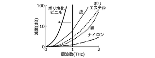
- FIG. 1 is a diagram showing the relationship between the attenuation factor and the frequency when an electromagnetic wave passes through a substance.
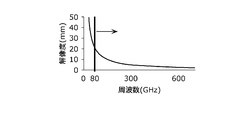
- FIG. 2 is a diagram showing the relationship between the frequency of electromagnetic waves and the resolution.
- FIG. 3 is a block diagram showing the configuration of the photographing apparatus according to the first embodiment.
- FIG. 4 is a schematic view showing the configuration of the light source according to the first embodiment.
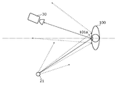
- FIG. 5 is a schematic view showing a cross section of the detector according to the first embodiment receiving the reflected wave.
- FIG. 6 is a schematic view showing a cross section of a detector according to the first comparative example receiving a reflected wave.
- FIG. 7 is a schematic view showing how the photographing apparatus according to the first embodiment is installed.
- FIG. 1 is a diagram showing the relationship between the attenuation factor and the frequency when an electromagnetic wave passes through a substance.
- FIG. 2 is a diagram showing the relationship between the frequency of electromagnetic waves and the resolution.
- FIG. 3 is a block diagram showing the configuration of the
- FIG. 8 is a block diagram showing the configuration of the photographing apparatus according to the second embodiment.
- FIG. 9 is a schematic view showing a cross section of the detector according to the second embodiment receiving the reflected wave.
- FIG. 10 is a schematic view showing a cross section of the detector according to the second comparative example receiving the reflected wave.
- FIG. 11 is a schematic view showing a cross section of a state in which the photographing apparatus according to the second embodiment is installed.
- FIG. 12 is a flowchart of the image analysis process.
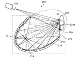
- FIG. 13 is a schematic view showing a part of the appearance of the photographing apparatus according to the modified example.
- the inventor has diligently studied a photographing device capable of detecting a dangerous object (for example, a knife) hidden under clothes or the like in a bag or the like.
- a dangerous object for example, a knife
- the inventor examined the relationship between the attenuation factor and frequency when electromagnetic waves are transmitted through substances that are materials such as clothes and bags.
- FIG. 1 is a diagram showing the relationship between the attenuation factor and the frequency when an electromagnetic wave passes through a substance.
- electromagnetic waves having a frequency of 1 THz or less can transmit most of the substances used as materials such as clothes and bags.
- the inventor examined the frequency that realizes the resolution that can capture the shape of a dangerous object.
- Equation 1 The relationship between the frequency (wavelength) of electromagnetic waves and the resolution (resolution) is expressed by (Equation 1) known as Abbe's equation.
- Equation 1 ⁇ is the resolution, ⁇ is the wavelength of the electromagnetic wave, NA is the numerical aperture of the lens, n is the refractive index of the medium between the object and the lens, and ⁇ is the maximum with respect to the optical axis of the light beam incident on the lens from the object. Indicates the angle.
- the entrance pupil diameter of the image pickup lens is D and the distance from the entrance pupil position of the image pickup lens to the object is d, d >> D, the approximation is obtained to obtain (Equation 2).
- the shape of a dangerous object such as a knife can be photographed by using an electromagnetic wave having a frequency of 80 GHz (0.08 THz) or higher.
- subterahertz which is an electromagnetic wave having a frequency of 0.08 THz or more and 1 THz or less, in order to perform photography capable of detecting dangerous substances hidden in a bag or the like under clothes or the like. We found that it is appropriate to use waves.
- sub-terahertz waves do not adversely affect the human body. Therefore, there is no problem from the viewpoint of safety to use the sub-terahertz wave as the electromagnetic wave radiated toward the human body.
- sub-terahertz waves are specularly reflected on the human body, metals, etc.
- a point light source here, sub-terahertz waves
- the shape of the human body, the shape of metallic dangerous objects such as blades, etc. must be photographed with high accuracy. Is difficult.
- the inventor examined the shape of the light source that radiates the sub-terahertz wave.
- the light source that emits the sub-terahertz wave is a surface light source
- the inventor can irradiate the object to be photographed with the sub-terahertz wave from various angles as compared with the case where the light source is a point light source. Since it is possible, it has been found that the shape of an object that mirror-reflects a sub-terahertz wave such as a human body or metal can be imaged more accurately than before.
- the inventor came up with the following imaging device based on the above findings.
- the photographing apparatus includes a first light source including a first radiation surface that radiates a sub-terahertz wave with respect to a measurement object, and a sub-terahertz wave radiated from the first radiation surface.
- a first detector including a first image sensor that receives a reflected wave from the measurement object.
- the above-mentioned photographing apparatus uses a sub-terahertz wave radiated from a first light source serving as a surface light source to perform photographing. Therefore, according to the above-mentioned photographing device, it is possible to photograph the shape of an object such as a human body or metal hidden under clothes or the like with higher accuracy than before.
- the first light source is a sub-terahertz wave radiated from the first radiation surface from one or more point light sources radiating a sub-terahertz wave and a sub-terahertz wave radiated from the one or more point light sources.
- the optical element may include a reflector that generates a sub-terahertz wave radiated from the first radiation surface by diffuse-reflecting the sub-terahertz wave radiated from the one or more point light sources. ..
- the optical element may include a diffuser plate that generates a sub-terahertz wave radiated from the first radiation surface by diffusing and transmitting the sub-terahertz wave radiated from the one or more point light sources.
- the first radiation surface may be a curved surface.
- the curved surface may include a part of the inner surface of the spheroidal surface.
- the spheroidal surface may be a spherical surface.
- the first radiation surface includes a part of the inner surface of the rotating elliptical surface
- the first light source is a point light source that emits a sub-terahertz wave and a sub-terahertz wave emitted from the point light source. It may include an optical element that generates a sub-terahertz wave radiated from the first radiation surface, and may be arranged at one of the two focal points of the rotating elliptical surface.
- a second light source including a second radiation surface that emits a sub-terahertz wave, and a second image sensor that receives a reflected wave of the sub-terahertz wave emitted from the second radiation surface.
- a second detector may be provided.
- the first image sensor outputs a first image based on the detected intensity of the sub-terahertz wave
- the second image sensor outputs a second image based on the detected intensity of the sub-terahertz wave.
- it may be provided with an image processing unit that comparatively brightly synthesizes the first image and the second image to generate a composite image and outputs the generated composite image.
- the image processing unit determines whether or not at least one of the first image and the second image contains an object having a predetermined feature, and the first image and the second image are described. When it is determined that at least one of the second image contains an object having the predetermined feature, a predetermined first detection signal is output, and the first image and the second image are output. If it is not determined that at least one of the images and the image contains the object having the predetermined feature, the composite image is generated, and the composite image further includes the object having the predetermined feature. When it is determined whether or not the composite image contains an object having the predetermined feature, a predetermined second detection signal may be output.
- the sub-terahertz wave may be an electromagnetic wave having a frequency of 0.08 THz or more and 1 THz or less.
- each of the embodiments shown here shows a specific example of the present disclosure. Therefore, the numerical values, shapes, components, arrangement and connection forms of the components, steps (processes), order of steps, etc. shown in the following embodiments are examples and do not limit the present disclosure. .. Further, each figure is a schematic view and is not necessarily exactly illustrated.
- the term plane means not only a plane that is exactly flat, but also a plane that is substantially flat.
- the term spheroidal surface means not only a surface that is exactly a spheroidal surface but also a surface that is substantially a spheroidal surface.
- the comprehensive or specific embodiment of the present disclosure may be realized by a recording medium such as a system, a method, an integrated circuit, a computer program or a computer-readable CD-ROM, and the system, the method, the integrated circuit, the computer. It may be realized by any combination of a program and a recording medium.
- FIG. 3 is a block diagram showing the configuration of the photographing apparatus 10 according to the first embodiment.
- the photographing apparatus 10 includes a light source 20, a detector 30, and an image processing unit 40.
- the light source 20 radiates a sub-terahertz wave to the object to be measured (here, the person 100).
- FIG. 4 is a schematic diagram showing the configuration of the light source 20.
- the light source 20 includes a point light source 21 and an optical element 23.
- the point light source 21 radiates a sub-terahertz wave radially in all directions around the point light source 21.
- the optical element 23 has a radiation surface 22 and generates a sub-terahertz wave radiated from the radiation surface 22 from the sub-terahertz wave radiated from the point light source 21.
- the radial surface 22 is a flat surface. Therefore, the optical element 23 functions as a surface light source that radiates a sub-terahertz wave from the plane radiation surface 22.
- the radiation surface of the sub-terahertz wave is a plane for convenience of explanation, but it may be an inner surface of a spheroid, an inner surface of a spherical surface, which will be described later, or an arbitrary curved surface.
- FIG. 5 is a schematic view showing a cross section of a light source 20 functioning as a surface light source that emits a sub-terahertz wave, and a detector 30 described later receiving a reflected wave from a measurement object.
- the optical element 23 is configured to include a diffuser plate 24, and the main plane on the front side thereof is a radiation surface 22.
- the diffuser plate 24 diffuses and transmits the sub-terahertz wave radiated from the point light source 21, thereby generating the sub-terahertz wave radiated from the radiation surface 22.
- the diffuser plate 24 has a flat plate shape parallel to the radiation surface 22 when viewed from a macro perspective. On the other hand, when viewed from a microscopic point of view, the diffuser plate 24 has minute undulations formed on the entire surface so that the transmitted sub-terahertz wave is diffused.
- the point light source 21 is arranged on the back side of the optical element 23.
- the sub-terahertz wave radiated from the point light source 21 penetrates into the inside of the optical element 23 from the main surface on the back side of the optical element 23 and reaches the diffuser plate 24.
- the sub-terahertz wave that has reached the diffuser plate 24 is diffused and transmitted through the diffuser plate 24.
- the sub-terahertz wave diffused and transmitted through the diffusion plate 24 propagates to the radiation surface 22 and is radiated to the outside from the radiation surface 22.
- the detector 30 includes an image sensor 31.
- the image sensor 31 converts an image of a sub-terahertz wave emitted from a subject into an electric signal according to its intensity. Then, the image sensor 31 generates an image based on the converted electric signal.
- imaging the fact that the image sensor 31 generates an image including an image of a subject is also referred to as “imaging”.
- the image sensor 31 Receives the reflected wave.
- the image sensor 31 receives the reflected wave from the region of the angle at which the mirror-reflected reflected wave is incident on the image sensor 31 among the body of the person 100 and the blade hidden by the person 100. Then, the image sensor 31 detects the intensity of the reflected wave to be received.
- the light source 20 functions as a surface light source that radiates a sub-terahertz wave from the radiation surface 22. Therefore, the light source 20 can irradiate the person 100 with sub-terahertz waves from various angles. Therefore, as shown in FIG. 5, the image sensor 31 reflects from a relatively wide range of the surface of the person 100, that is, the body of the person 100 and the surface of the blade hidden by the person 100. Can receive waves. Therefore, the photographing device 10 can image a relatively wide area 101 of the body of the person 100 and the surface of the blade hidden by the person 100.
- FIG. 6 shows a first image pickup device according to a first comparative example in which the optical element 23 is removed from the light source 20, that is, the first configuration in which the sub-terahertz wave radiated by the point light source 21 is radiated to the outside as it is. It is a schematic diagram which shows the cross section of the state which the detector 30 receives a reflected wave in the photographing apparatus which concerns on a comparative example.
- the photographing apparatus according to the first comparative example in the image sensor 31, the reflected wave reflected from the mirror surface of the body of the person 100 and the surface of the blade hidden by the person 100 is the image sensor 31. Only the reflected wave from the region 101a at an angle incident on the can be received. Therefore, the photographing apparatus according to the first comparative example can image only a relatively narrow range 101a of the body of the person 100 and the surface of the blade hidden by the person 100.
- the photographing device 10 according to the first embodiment can image the body of the person 100 and the shape of the blade hidden by the person 100 with higher accuracy than the photographing device according to the first comparative example.
- the detector 30 outputs the image generated by the image sensor 31 to the image processing unit 40.
- the image processing unit 40 When the image processing unit 40 receives an image from the detector 30, the image processing unit 40 outputs the received image to the outside, performs image processing on the received image, and outputs the result of the image processing to the outside.
- the image processing performed by the image processing unit 40 determines, for example, whether or not the image output from the detector 30 includes an object having a predetermined feature (for example, an object having the feature of a blade), and determines. When it is determined that an object having the characteristics of the above is included, the process may be a process of outputting a predetermined detection signal (for example, an alarm indicating that the object having the characteristics of the blade is being photographed).
- the image processing unit 40 includes, for example, a processor and a memory, and the processor may be realized by executing a program stored in the memory.
- the photographing device 10 having the above configuration is installed, for example, in a passage in an airport, near a ticket gate of a station, or the like.
- FIG. 7 is a schematic view showing how the photographing device 10 is installed in the passage in the airport.
- the photographing device 10 may be installed, for example, in which the optical element 23 and the detector 30 are embedded inside the wall of the crank-shaped passage 200 at the airport.
- the sub-terahertz wave radiated from the radiating surface 22 inside the wall passes through the wall and irradiates the person 100. Then, the reflected wave of the sub-terahertz wave reflected by the person 100 passes through the wall again and is incident on the detector 30. As a result, the photographing device 10 can photograph a dangerous object such as a knife hidden under clothes or the like by the person 100 passing through the passage 200.
- FIG. 8 is a block diagram showing the configuration of the photographing apparatus 10a according to the second embodiment.
- the light source 20 is changed to the first light source 20a and the second light source 20b from the photographing device 10 according to the first embodiment, and the detector 30 is the first detection.
- the device 30a and the second detector 30b are changed, and the image processing unit 40 is changed to the image processing unit 40a.
- the first light source 20a radiates a sub-terahertz wave to the object to be measured (here, the person 100).
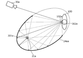
- FIG. 9 is a schematic view showing a cross section showing the configuration of the first light source 20a, how the first light source 20a functions as a surface light source, and how the first detector 30a, which will be described later, receives the reflected wave. ..
- the first light source 20a includes a point light source 21a and an optical element 23a.
- the point light source 21a radiates a sub-terahertz wave radially in all directions around the point light source 21a.
- the optical element 23a has a first radiation surface 22a, and generates a sub-terahertz wave radiated from the first radiation surface 22a from the sub-terahertz wave radiated from the point light source 21a.
- the first radial surface 22a is the inner surface of the spheroidal surface. Therefore, the optical element 23a functions as a surface light source that radiates a sub-terahertz wave from the first radiation surface 22a, which is the inner surface of the spheroidal surface.
- the optical element 23a is configured to include a reflector 24a, and the curved surface inside the optical element 23a is a first radiation surface 22a.
- the reflector 24a diffusely reflects the sub-terahertz wave radiated from the point light source 21a to generate the sub-terahertz wave radiated from the first radiation surface 22a. From a macroscopic point of view, the reflector 24a has a similar shape to the first radiation surface 22a, which is equal to or larger than the first radiation surface 22a, and the positions of the two focal points are the first radiation, respectively. It coincides with the positions of the two focal points on the surface 22a. On the other hand, when viewed from a microscopic point of view, the reflector 24a has minute undulations formed on the entire surface of the reflecting surface so that the reflected sub-terahertz wave is diffused.
- the point light source 21a is arranged at the focal point 301a of one of the two focal points of the first radiation surface 22a.
- the sub-terahertz wave radiated from the point light source 21a penetrates into the inside of the optical element 23a from the first radiation surface 22a and reaches the reflector 24a.
- the sub-terahertz wave that has reached the reflector 24a is diffusely reflected by the reflector 24a.
- the sub-terahertz wave diffusely reflected by the reflector 24a propagates to the first radiation surface 22a and is radiated to the outside from the first radiation surface 22a.
- the externally radiated sub-terahertz wave irradiates, for example, a person 100 in the vicinity of the other focal point 302a of the two focal points of the first radiation surface 22a.
- the second light source 20b in FIG. 8 has the same function as the first light source 20a, and its shape has a mirror image relationship with the first light source 20a. Therefore, the second light source 20b is replaced with the point light source 21b from the description of the first light source 20a, except that the shape of the second light source 20b has a mirror image relationship with the first light source 20a, and the optical element 23a Is replaced with an optical element 23b, a reflecting plate 24a is replaced with a reflecting plate 24b, one focal point 301a is replaced with one focal point 301b, and the other focal point 302a is replaced with the other focal point 302b.
- the first detector 30a includes the first image sensor 31a.
- the first detector 30a is the same as the detector 30 according to the first embodiment. That is, the first image sensor 31a is the same as the image sensor 31 according to the first embodiment.
- the second detector 30b is the same as the first detector 30a. Therefore, the second detector 30b will be described by replacing the first image sensor 31a with the second image sensor 31b from the description of the first detector 30a.
- the first light source 20a functions as a surface light source that radiates a sub-terahertz wave from the first radiation surface 22a. Therefore, the first light source 20a can irradiate the person 100 near the other focal point 302a with the sub-terahertz wave from various angles. Therefore, as shown in FIG. 9, the first image sensor 31a covers a relatively wide range of the surface of the person 100, that is, the body of the person 100 and the surface of the blade hidden by the person 100. Can receive the reflected wave of. Therefore, the photographing device 10a can image a relatively wide area 102 of the body of the person 100 and the surface of the blade hidden by the person 100.
- FIG. 10 shows that the first detector 30a receives the reflected wave in the photographing apparatus according to the second comparative example in which the reflector 24a is changed from the first light source 20a to the reflector 24aa.
- the reflector 24aa has the same shape as the reflector 24a when viewed from a macroscopic viewpoint, while the reflecting surface is mirror-reflected so that the reflected subterahertz wave is mirror-reflected when viewed from a microscopic viewpoint.
- the entire surface is formed smoothly. Therefore, all the sub-terahertz waves radiated from one focal point 301a and reflected by the reflector 24aa travel toward the other focal point 302a regardless of where the reflecting plate 24aa is reflected.
- the first image sensor 31a is the body of the person 100 near the other focal point 302a and the surface of the blade hidden by the person 100.
- the photographing apparatus according to the second comparative example can image only a relatively narrow range 102a of the body of the person 100 and the surface of the blade hidden by the person 100.
- the photographing device 10a according to the second embodiment can image the body of the person 100 and the shape of the blade hidden by the person 100 with higher accuracy than the photographing device according to the second comparative example.
- the first detector 30a and the second detector 30b transmit the first image and the second image generated by the first image sensor 31a and the second image sensor 31b to the image processing unit 40a, respectively. Output.
- the image processing unit 40a When the image processing unit 40a receives the first image and the second image from the first detector 30a and the second detector 30b, respectively, the image processing unit 40a sends the received first image and the second image to the outside. At the same time as outputting, image processing is performed on the received first image and second image, and the result of the image processing is output to the outside.
- the image processing performed by the image processing unit 40a is, for example, an object having predetermined characteristics in the first image and the second image output from the first detector 30a and the second detector 30b (for example, a blade).
- an object having the above-mentioned characteristics is included, and when it is determined that at least one of the first image and the second image contains an object having a predetermined characteristic.
- It may be a process of outputting a predetermined detection signal (for example, an alarm indicating that an object having the characteristics of a blade is being photographed).
- the image processing performed by the image processing unit 40a further determines that at least one of the first image and the second image contains an object having a predetermined feature, the first image.
- the image processing unit 40a may be realized by, for example, including a processor and a memory, and the processor executes a program stored in the memory.
- the photographing device 10a having the above configuration is installed, for example, in the passage in the airport or near the ticket gate of the station.
- FIG. 11 is a schematic view showing a cross section of the photographing device 10a installed in the passage near the ticket gate of the station.
- the photographing device 10a may be installed, for example, in which the optical element 23a and the optical element 23b are embedded inside the wall of the passage 400 near the ticket gate of the station. More specifically, the photographing apparatus 10a is installed, for example, by embedding the optical element 23a inside the wall 401a which is one side wall of the passage 400, and the optical element 23b is installed in the wall 401b which is the other side wall of the passage 400. It may be embedded and installed inside the. As described above, in the photographing apparatus 10a, the first light source 20a and the second light source 20b may be installed with the passage 400 interposed therebetween, and further, the first detector 30a and the second detector 30b may be installed. And may be installed across the passage 400.
- the first detector 30a is a reflected wave of the sub-terahertz wave emitted from the first radiation surface 22a and the second radiation surface 22b by the measurement object (here, the person 100) on the passage 400.
- the intensity of the subterahertz wave is detected by the first image sensor 31a
- the second detector 30b is the object to be measured on the passage 400 of the sub-terahertz wave emitted from the first radiation surface 22a and the second radiation surface 22b.
- the intensity of the reflected wave (here, the person 100) is detected by the second image sensor 31b.
- the optical element 23a and the optical element 23b may be installed so that the other focal point 302a of the optical element 23a and the other focal point 302b of the optical element 23b substantially coincide with each other on the center line of the passage 400.
- the sub-terahertz wave radiated from the point light source 21a and the sub-terahertz wave radiated from the point light source 21b are placed in a region near the other focal point 302a and the other focal point 302b (hereinafter,). , Also referred to as the "focus area”) can be irradiated from various angles. Therefore, as shown in FIG.
- the first image sensor 31a and the second image sensor 31b included in the first detector 30a and the second detector 30b are the person 100 walking in the focal region.
- the reflected wave can be received from a relatively wide range of the surface of the person 100, that is, the body of the person 100 and the surface of the blade hidden by the person 100. Therefore, the photographing device 10a can image a relatively wide area 103 of the body of the person 100 and the surface of the blade hidden by the person 100.
- the first image sensor 31a and the second image sensor 31b included in the first detector 30a and the second detector 30b each receive reflected waves from the region 103 at different angles. To do. Therefore, the photographing device 10a can image the body of the person 100 and the blade hidden by the person 100, which are the same subjects, from different angles.
- the photographing device 10a performs image analysis processing as an example.
- the photographing device 10a captures the first image and the second image, and based on the captured first image and the second image, an object having the characteristics of a blade is photographed. This is a process of outputting a detection signal, which is an alarm indicating that the image is running.
- FIG. 12 is a flowchart of the image analysis process performed by the photographing apparatus 10a.
- the image analysis process is started when a person invades the focal area.
- the photographing device 10a detects that the person has invaded the focal area.
- the photographing device 10a detects that a person has invaded the focal area by receiving, for example, a signal indicating that the person has invaded the focal area from an external sensor that detects that the person has invaded the focal area. You may.
- the first light source 20a and the second light source 20b radiate a sub-terahertz wave at the same timing in synchronization with each other (step S100). Further, the first detector 30a and the second detector 30b entered the focal region at the timing when the first light source 20a and the second light source 20b emit the sub-terahertz wave in synchronization with each other. An image of a person is taken (step S110). Then, the first detector 30a and the second detector 30b output the first image and the second image to the image processing unit 40a, respectively.
- the image processing unit 40a receives the output first image and the second image, and receives the first image and the second image. Is output to the outside (step S120). Then, the image processing unit 40a determines whether or not at least one of the first image and the second image includes an object having the characteristic of the blade, which is a predetermined characteristic (step S130).
- step S130 when it is not determined that at least one of the first image and the second image contains an object having a predetermined feature (step S130: No), the image processing unit 40a , The first image and the second image are comparatively brightly combined to generate a composite image, and the generated composite image is output to the outside (step S140). Then, the image processing unit 40a determines whether or not the generated composite image includes an object having the characteristics of the blade, which is a predetermined characteristic (step S150).
- step S130 when it is determined that at least one of the first image and the second image contains an object having a predetermined feature (step S130: Yes), and in the process of step S150.
- step S150: Yes the image processing unit 40a gives an alarm indicating that the object having the feature of the blade is being photographed.
- a certain detection signal is output to the outside (step S160).
- step S160 When the process of step S160 is completed, and when it is not determined in the process of step S150 that the composite image contains an object having a predetermined feature (step S150: No), the photographing device 10a captures the image. End the analysis process.
- the photographing apparatus 10a includes a first light source 20a including an optical element 23a having a first radiating surface 22a which is an inner surface of a spheroid surface, and a second light source 20a which is an inner surface of the spheroidal surface. It has been described that the configuration includes a second light source 20b including an optical element 23b having a radiation surface 22b of the above.
- the photographing apparatus according to the modified example according to another example of the present disclosure is the inner surface of the rotating ellipsoidal surface instead of the optical element 23a from the photographing apparatus 10a according to the second embodiment.
- the first light source according to the modified example in which the shape of the radial surface 22a of 1 is changed to the inner surface of a spherical surface is provided, and instead of the optical element 23b, the shape of the second radial surface 22b, which is the inner surface of the rotating ellipsoidal surface, is spherical. It may be modified and configured to include a second light source according to the modified example on the inner surface of the.
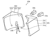
- FIG. 13 is a schematic view showing a part of the appearance of the photographing apparatus according to the modified example.
- the first light source 20c according to the modified example includes a point light source 21a and an optical element 23c having a first radiation surface 22c which is an inner surface of a spherical surface. Consists of.
- the point light source 21a is arranged near the center of the spherical surface.
- the second light source 20d according to the modified example includes a point light source 21b and an optical element 23d having a second radiation surface 22d which is an inner surface of a spherical surface.
- the point light source 21b is arranged near the center of the spherical surface.
- the optical element 23 has been described as being configured to include the diffuser plate 24.
- the optical element 23 may be the diffuser plate 24 itself. In this case, the surface of the diffusion plate 24 becomes the radiation surface 22.
- the optical element 23a and the optical element 23b have been described as including the reflector 24a and the reflector 24b, respectively.
- the optical element 23a and the optical element 23b may be the reflector 24a itself and the reflector 24b itself, respectively.
- the reflective surface of the reflector 24a and the reflective surface of the reflector 24b become the first radiation surface 22a and the second radiation surface 22b, respectively.
- the light source 20 includes one point light source 21.
- the number of point light sources included in the light source 20 is not necessarily limited to one, and may be plural.
- the optical element 23 generates a sub-terahertz wave radiated from the radiation surface 22 from the sub-terahertz wave radiated from these a plurality of point light sources.
- the first light source 20a and the second light source 20b include one point light source 21a and one point light source 21b, respectively.
- the number of point light sources included in the first light source 20a and the second light source 20b is not necessarily limited to one, and may be plural.
- the optical element 23a and the optical element 23b generate a sub-terahertz wave radiated from the first radiation surface 22a and the second radiation surface 22b from the sub-terahertz waves radiated from the plurality of point light sources, respectively. It will be.
- One aspect of the present disclosure may be not only the photographing apparatus according to the first and second embodiments, but also an imaging method in which a characteristic component included in the photographing apparatus is a step.
- One aspect of the present disclosure may be a program that causes a computer to perform each characteristic step included in the photographing method.
- one aspect of the present disclosure may be a computer-readable non-temporary recording medium on which such a program is recorded.
- This disclosure can be widely used in a photographing device for photographing an object.
- Imaging device 20 Light source 20a, 20c First light source 20b, 20d Second light source 21, 21a, 21b Point light source 22 Radiation surface 22a, 22c First radiation surface 22b, 22d Second radiation surface 23, 23a , 23b, 23c, 23d Optical element 24 Diffusing plate 24a, 24aa, 24b Reflector 30 Detector 30a First detector 30b Second detector 31 Image sensor 31a First image sensor 31b Second image sensor 40, 40a Image processing unit 100 People 101, 101a, 102, 102a, 103 Area 200, 400 Passage 301a, 301b One light source 302a, 302b The other light source 401a, 401b Wall
Abstract
This photography device (10) comprises a light source (20) including a radiation surface (22) for radiating a sub-terahertz wave onto an object under measurement and a detector (30) including an image sensor (31) for detecting the intensity of a sub-terahertz wave that has been radiated by the radiation surface (22) and reflected by the object under measurement.
Description
撮影装置に関する。
Regarding the shooting device.
従来、衣服等の下に隠れて直接視認することができない物体を撮影する撮影装置が知られている(例えば、特許文献1参照)。
Conventionally, a photographing device for photographing an object hidden under clothes or the like and not directly visible is known (see, for example, Patent Document 1).
従来、衣服等を透過する電磁波を人物に向けて放射する点光源と、点光源から放射された電磁波の反射波を受波する検知器とを備え、その人物の衣服等の下に隠れている物体を撮影する撮影装置が知られている。上記従来の撮影装置において、衣服等を透過する電磁波は、人体、金属等に対して鏡面反射する。このため、上記従来の撮影装置では、点光源から放射された電磁波を鏡面反射する人体、金属等のうち、反射波が検知器に入射する角度となる領域しか撮影することができない。従って、上記従来の撮影装置では、衣服等の下に隠れて直接視認することができない人体、金属等の形状を高精度に撮影することが困難である。
Conventionally, a point light source that radiates an electromagnetic wave transmitted through clothes or the like toward a person and a detector that receives a reflected wave of an electromagnetic wave radiated from the point light source are provided and hidden under the person's clothes or the like. A photographing device for photographing an object is known. In the above-mentioned conventional photographing apparatus, electromagnetic waves transmitted through clothes and the like are specularly reflected by the human body, metal and the like. Therefore, with the above-mentioned conventional photographing apparatus, it is possible to photograph only a region of a human body, a metal, or the like that mirror-reflects an electromagnetic wave radiated from a point light source at an angle at which the reflected wave is incident on the detector. Therefore, with the above-mentioned conventional photographing apparatus, it is difficult to photograph the shape of a human body, metal, or the like that is hidden under clothes or the like and cannot be directly visually recognized with high accuracy.
そこで、本発明は、衣服等の下に隠れて直接視認することができない物体の形状を、従来よりも精度よく撮影することができる撮影装置を提供することを目的とする。
Therefore, an object of the present invention is to provide a photographing device capable of photographing the shape of an object hidden under clothes or the like and which cannot be directly visually recognized, with higher accuracy than before.
本開示の一態様に係る撮影装置は、測定対象物に対してサブテラヘルツ波を放射する第1の放射面を含む第1の光源と、前記第1の放射面より放射されたサブテラヘルツ波の、前記測定対象物による反射波の強度を検出する第1のイメージセンサを含む第1の検出器と、を備える。なお、「サブテラヘルツ波」の語は、0.08THz以上1THz以下の周波数の電磁波を意味する。
The photographing apparatus according to one aspect of the present disclosure includes a first light source including a first radiation surface that radiates a sub-terahertz wave with respect to a measurement object, and a sub-terahertz wave radiated from the first radiation surface. A first detector including a first image sensor for detecting the intensity of the reflected wave by the measurement object. The term "sub-terahertz wave" means an electromagnetic wave having a frequency of 0.08 THz or more and 1 THz or less.
本開示の一態様に係る撮影装置によれば、衣服等の下に隠れて直接視認することができない物体の形状を、従来よりも精度よく撮影することができる。
According to the photographing apparatus according to one aspect of the present disclosure, it is possible to photograph the shape of an object hidden under clothes or the like that cannot be directly visually recognized, more accurately than before.
(本開示の一態様を得るに至った経緯)
発明者は、衣服等の下、カバンの中等に隠し持つ危険物(例えば、刃物等)の検知が可能となる撮影を行うことができる撮影装置について、鋭意検討を行った。 (History of obtaining one aspect of the present disclosure)
The inventor has diligently studied a photographing device capable of detecting a dangerous object (for example, a knife) hidden under clothes or the like in a bag or the like.
以下、発明者が行った検討の内容について説明する。
The contents of the examination conducted by the inventor will be described below.
発明者は、衣服、カバン等の材料となる物質を電磁波が透過する際の、減衰率と周波数との関係について検討した。
The inventor examined the relationship between the attenuation factor and frequency when electromagnetic waves are transmitted through substances that are materials such as clothes and bags.
図1は、電磁波が物質を透過する際の、減衰率と周波数との関係を示す図である。
FIG. 1 is a diagram showing the relationship between the attenuation factor and the frequency when an electromagnetic wave passes through a substance.
図1に示すように、1THz以下の周波数の電磁波は、衣服、カバン等の材料となる物質の多くを透過することができる。
As shown in FIG. 1, electromagnetic waves having a frequency of 1 THz or less can transmit most of the substances used as materials such as clothes and bags.
発明者は、上記検討の結果、衣服等の下、カバンの中等に隠し持った危険物を検知するためには、1THz以下の周波数の電磁波を利用することが適切であるとの知見を得た。
As a result of the above examination, the inventor has found that it is appropriate to use an electromagnetic wave having a frequency of 1 THz or less in order to detect a dangerous substance hidden in a bag or the like under clothes or the like.
また、発明者は、危険物の形状を撮影することができる解像度を実現する周波数について検討した。
In addition, the inventor examined the frequency that realizes the resolution that can capture the shape of a dangerous object.
電磁波の周波数(波長)と解像度(分解能)との関係は、アッベの式として知られている(式1)により表現される。
The relationship between the frequency (wavelength) of electromagnetic waves and the resolution (resolution) is expressed by (Equation 1) known as Abbe's equation.
式1において、δは分解能、λは電磁波の波長、NAはレンズの開口数、nは物体とレンズとの間の媒質の屈折率、θは、物体からレンズに入射する光線の光軸に対する最大角度を示す。ここで、撮像レンズの入射瞳径をDとし、撮像レンズの入射瞳位置から物体までの距離d、d≫Dであるとして近似をすると、(式2)が得られる。
In Equation 1, δ is the resolution, λ is the wavelength of the electromagnetic wave, NA is the numerical aperture of the lens, n is the refractive index of the medium between the object and the lens, and θ is the maximum with respect to the optical axis of the light beam incident on the lens from the object. Indicates the angle. Here, if the entrance pupil diameter of the image pickup lens is D and the distance from the entrance pupil position of the image pickup lens to the object is d, d >> D, the approximation is obtained to obtain (Equation 2).
図2は、空気環境下を想定してn=1とし、D=0.5m、d=2.5mの条件下で、(式2)をグラフ化した図である。
FIG. 2 is a graph of (Equation 2) under the conditions of n = 1 and D = 0.5 m and d = 2.5 m assuming an air environment.
図2に示すように、80GHz(0.08THz)以上の周波数の電磁波を利用することで、刃物等の危険物の形状を撮影することができる。
As shown in FIG. 2, the shape of a dangerous object such as a knife can be photographed by using an electromagnetic wave having a frequency of 80 GHz (0.08 THz) or higher.
発明者は、上記検討の結果、刃物等の危険物の形状を撮影するためには、0.08THz以上の周波数の電磁波を利用することが適切であるとの知見を得た。
As a result of the above examination, the inventor has found that it is appropriate to use an electromagnetic wave having a frequency of 0.08 THz or higher in order to photograph the shape of a dangerous object such as a knife.
すなわち、発明者は、これらの検討を通じて、衣服等の下、カバンの中等に隠し持つ危険物の検知が可能となる撮影を行うためには、0.08THz以上1THz以下の周波数の電磁波であるサブテラヘルツ波を利用することが適切であるとの知見を得た。
That is, the inventor, through these examinations, subterahertz, which is an electromagnetic wave having a frequency of 0.08 THz or more and 1 THz or less, in order to perform photography capable of detecting dangerous substances hidden in a bag or the like under clothes or the like. We found that it is appropriate to use waves.
また、サブテラヘルツ波は、人体に悪影響を生じないことが知られている。このため、人体に向けて放射する電磁波としてサブテラヘルツ波を利用することは、安全性の観点から問題はない。
It is also known that sub-terahertz waves do not adversely affect the human body. Therefore, there is no problem from the viewpoint of safety to use the sub-terahertz wave as the electromagnetic wave radiated toward the human body.
一方、サブテラヘルツ波は、人体、金属等に対して鏡面反射する。このため、従来のように、点光源から放射された電磁波(ここでは、サブテラヘルツ波)を利用する撮影では、人体の形状、刃物等といった金属性の危険物の形状を高精度に撮影することが困難である。この問題を解決するために、発明者は、サブテラヘルツ波を放射する光源の形状等について検討した。その結果、発明者は、サブテラヘルツ波を放出する光源が面光源であれば、点光源である場合と比べて、撮影対象となる物体に対して多様な角度からサブテラヘルツ波を照射することが可能となるため、人体、金属等のサブテラヘルツ波を鏡面反射する物体の形状を、従来よりも精度よく撮像することができるとの知見を得た。
On the other hand, sub-terahertz waves are specularly reflected on the human body, metals, etc. For this reason, in conventional photography using electromagnetic waves radiated from a point light source (here, sub-terahertz waves), the shape of the human body, the shape of metallic dangerous objects such as blades, etc. must be photographed with high accuracy. Is difficult. In order to solve this problem, the inventor examined the shape of the light source that radiates the sub-terahertz wave. As a result, if the light source that emits the sub-terahertz wave is a surface light source, the inventor can irradiate the object to be photographed with the sub-terahertz wave from various angles as compared with the case where the light source is a point light source. Since it is possible, it has been found that the shape of an object that mirror-reflects a sub-terahertz wave such as a human body or metal can be imaged more accurately than before.
発明者は、上記知見に基づいて、下記撮影装置に想到した。
The inventor came up with the following imaging device based on the above findings.
本開示の一態様に係る撮影装置は、測定対象物に対してサブテラヘルツ波を放射する第1の放射面を含む第1の光源と、前記第1の放射面より放射されたサブテラヘルツ波の、前記測定対象物による反射波を受波する第1のイメージセンサを含む第1の検出器と、を備える。
The photographing apparatus according to one aspect of the present disclosure includes a first light source including a first radiation surface that radiates a sub-terahertz wave with respect to a measurement object, and a sub-terahertz wave radiated from the first radiation surface. A first detector including a first image sensor that receives a reflected wave from the measurement object.
上記撮影装置は、面光源となる第1の光源から放射されたサブテラヘルツ波を利用して撮影を行う。このため、上記撮影装置によると、衣服等の下に隠れて直接視認することができない人体、金属等といった物体の形状を、従来よりも精度よく撮影することができる。
The above-mentioned photographing apparatus uses a sub-terahertz wave radiated from a first light source serving as a surface light source to perform photographing. Therefore, according to the above-mentioned photographing device, it is possible to photograph the shape of an object such as a human body or metal hidden under clothes or the like with higher accuracy than before.
また、前記第1の光源は、サブテラヘルツ波を放射する1以上の点光源と、前記1以上の点光源から放射されたサブテラヘルツ波から、前記第1の放射面から放射されるサブテラヘルツ波を生成する光学素子と、を含むとしてもよい。
Further, the first light source is a sub-terahertz wave radiated from the first radiation surface from one or more point light sources radiating a sub-terahertz wave and a sub-terahertz wave radiated from the one or more point light sources. May include an optical element that produces.
また、前記光学素子は、前記1以上の点光源から放射されたサブテラヘルツ波を拡散反射することで、前記第1の放射面から放射されるサブテラヘルツ波を生成する反射板を含むとしてもよい。
Further, the optical element may include a reflector that generates a sub-terahertz wave radiated from the first radiation surface by diffuse-reflecting the sub-terahertz wave radiated from the one or more point light sources. ..
また、前記光学素子は、前記1以上の点光源から放射されたサブテラヘルツ波を拡散透過することで、前記第1の放射面から放射するサブテラヘルツ波を生成する拡散板を含むとしてもよい。
Further, the optical element may include a diffuser plate that generates a sub-terahertz wave radiated from the first radiation surface by diffusing and transmitting the sub-terahertz wave radiated from the one or more point light sources.
また、前記第1の放射面は、曲面であるとしてもよい。
Further, the first radiation surface may be a curved surface.
また、前記曲面は、回転楕円面の内面の一部を含むとしてもよい。
Further, the curved surface may include a part of the inner surface of the spheroidal surface.
また、前記回転楕円面は、球面であるとしてもよい。
Further, the spheroidal surface may be a spherical surface.
また、前記第1の放射面は、回転楕円面の内面の一部を含み、前記第1の光源は、サブテラヘルツ波を放射する点光源と、前記点光源から放射されたサブテラヘルツ波から、前記第1の放射面から放射されるサブテラヘルツ波を生成する光学素子と、を含み、前記回転楕円面の2つの焦点のうちの一方に配置されるとしてもよい。
Further, the first radiation surface includes a part of the inner surface of the rotating elliptical surface, and the first light source is a point light source that emits a sub-terahertz wave and a sub-terahertz wave emitted from the point light source. It may include an optical element that generates a sub-terahertz wave radiated from the first radiation surface, and may be arranged at one of the two focal points of the rotating elliptical surface.
また、さらに、サブテラヘルツ波を放射する第2の放射面を含む第2の光源と、前記第2の放射面より放射されたサブテラヘルツ波の反射波を受波する第2のイメージセンサを含む第2の検出器と、を備えるとしてもよい。
Further, it further includes a second light source including a second radiation surface that emits a sub-terahertz wave, and a second image sensor that receives a reflected wave of the sub-terahertz wave emitted from the second radiation surface. A second detector may be provided.
また、前記第1のイメージセンサは、検出したサブテラヘルツ波の強度に基づく第1の画像を出力し、前記第2のイメージセンサは、検出したサブテラヘルツ波の強度に基づく第2の画像を出力し、さらに、前記第1の画像と前記第2の画像とを比較明合成して合成画像を生成し、生成した前記合成画像を出力する画像処理部を備えるとしてもよい。
Further, the first image sensor outputs a first image based on the detected intensity of the sub-terahertz wave, and the second image sensor outputs a second image based on the detected intensity of the sub-terahertz wave. Further, it may be provided with an image processing unit that comparatively brightly synthesizes the first image and the second image to generate a composite image and outputs the generated composite image.
また、前記画像処理部は、前記第1の画像と前記第2の画像との少なくともどちらかに、所定の特徴を有する物体が含まれているか否かを判定し、前記第1の画像と前記第2の画像との少なくともどちらかに、前記所定の特徴を有する物体が含まれていると判定する場合には、所定の第1の検知信号を出力し、前記第1の画像と前記第2の画像との少なくともどちらかに、前記所定の特徴を有する物体が含まれていると判定しない場合には、前記合成画像を生成し、さらに、前記合成画像に前記所定の特徴を有する物体が含まれているか否かを判定し、前記合成画像に前記所定の特徴を有する物体が含まれていると判定する場合には、所定の第2の検知信号を出力するとしてもよい。
Further, the image processing unit determines whether or not at least one of the first image and the second image contains an object having a predetermined feature, and the first image and the second image are described. When it is determined that at least one of the second image contains an object having the predetermined feature, a predetermined first detection signal is output, and the first image and the second image are output. If it is not determined that at least one of the images and the image contains the object having the predetermined feature, the composite image is generated, and the composite image further includes the object having the predetermined feature. When it is determined whether or not the composite image contains an object having the predetermined feature, a predetermined second detection signal may be output.
また、前記サブテラヘルツ波は、0.08THz以上1THz以下の周波数の電磁波であるとしてもよい。
Further, the sub-terahertz wave may be an electromagnetic wave having a frequency of 0.08 THz or more and 1 THz or less.
以下、本開示の一態様に係る撮影装置の具体例について、図面を参照しながら説明する。ここで示す実施の形態は、いずれも本開示の一具体例を示すものである。従って、以下の実施の形態で示される数値、形状、構成要素、構成要素の配置及び接続形態、並びに、ステップ(工程)及びステップの順序等は、一例であって本開示を限定するものではない。また、各図は、模式図であり、必ずしも厳密に図示されたものではない。以下において、平面という用語は、正確に平面である面だけでなく、実質的に平面である面を意味する。また、以下において、回転楕円面という用語は、正確に回転楕円面である面だけでなく、実質的に回転楕円面である面を意味する。
Hereinafter, a specific example of the photographing apparatus according to one aspect of the present disclosure will be described with reference to the drawings. Each of the embodiments shown here shows a specific example of the present disclosure. Therefore, the numerical values, shapes, components, arrangement and connection forms of the components, steps (processes), order of steps, etc. shown in the following embodiments are examples and do not limit the present disclosure. .. Further, each figure is a schematic view and is not necessarily exactly illustrated. In the following, the term plane means not only a plane that is exactly flat, but also a plane that is substantially flat. Further, in the following, the term spheroidal surface means not only a surface that is exactly a spheroidal surface but also a surface that is substantially a spheroidal surface.
なお、本開示の包括的又は具体的な態様は、システム、方法、集積回路、コンピュータプログラム又はコンピュータ読み取り可能なCD-ROMなどの記録媒体で実現されてもよく、システム、方法、集積回路、コンピュータプログラム及び記録媒体の任意な組み合わせで実現されてもよい。
In addition, the comprehensive or specific embodiment of the present disclosure may be realized by a recording medium such as a system, a method, an integrated circuit, a computer program or a computer-readable CD-ROM, and the system, the method, the integrated circuit, the computer. It may be realized by any combination of a program and a recording medium.
(実施の形態1)
ここでは、人物に対してサブテラヘルツ波を放射し、その人物により反射された反射波を受波し、受波した反射波の強度を検出することで、その人物が衣服等の下に隠し持つ刃物等の危険物を撮影する撮影装置について説明する。 (Embodiment 1)
Here, by radiating a sub-terahertz wave to a person, receiving the reflected wave reflected by the person, and detecting the intensity of the reflected wave received, the knife that the person hides under clothes or the like. An imaging device for photographing dangerous objects such as the above will be described.
図3は、実施の形態1に係る撮影装置10の構成を示すブロック図である。
FIG. 3 is a block diagram showing the configuration of the photographing apparatus 10 according to the first embodiment.
図3に示すように、撮影装置10は、光源20と、検出器30と、画像処理部40とを備える。
As shown in FIG. 3, the photographing apparatus 10 includes a light source 20, a detector 30, and an image processing unit 40.
光源20は、測定対象物(ここでは、人物100)に対してサブテラヘルツ波を放射する。
The light source 20 radiates a sub-terahertz wave to the object to be measured (here, the person 100).
図4は、光源20の構成を示す模式図である。
FIG. 4 is a schematic diagram showing the configuration of the light source 20.
図4に示すように、光源20は、点光源21と、光学素子23とを含んで構成される。
As shown in FIG. 4, the light source 20 includes a point light source 21 and an optical element 23.
点光源21は、サブテラヘルツ波を点光源21の周囲の全方位へ放射状に放射する。
The point light source 21 radiates a sub-terahertz wave radially in all directions around the point light source 21.
光学素子23は、放射面22を有し、点光源21から放射されたサブテラヘルツ波から、放射面22から放射するサブテラヘルツ波を生成する。ここで、放射面22は、平面である。このため、光学素子23は、平面である放射面22からサブテラヘルツ波を放射する面光源として機能する。ここで、サブテラヘルツ波の放射面は、説明の便宜上、平面としているが、後述する回転楕円体の内面、球面の内面でもよく、さらに、任意の曲面であってもよい。
The optical element 23 has a radiation surface 22 and generates a sub-terahertz wave radiated from the radiation surface 22 from the sub-terahertz wave radiated from the point light source 21. Here, the radial surface 22 is a flat surface. Therefore, the optical element 23 functions as a surface light source that radiates a sub-terahertz wave from the plane radiation surface 22. Here, the radiation surface of the sub-terahertz wave is a plane for convenience of explanation, but it may be an inner surface of a spheroid, an inner surface of a spherical surface, which will be described later, or an arbitrary curved surface.
図5は、光源20がサブテラヘルツ波を放出する面光源として機能する様子、及び、後述する検出器30が、測定対象物による反射波を受波する様子の断面を示す模式図である。
FIG. 5 is a schematic view showing a cross section of a light source 20 functioning as a surface light source that emits a sub-terahertz wave, and a detector 30 described later receiving a reflected wave from a measurement object.
図5に示すように、光学素子23は、拡散板24を含んで構成され、その表側の主平面を放射面22とする。
As shown in FIG. 5, the optical element 23 is configured to include a diffuser plate 24, and the main plane on the front side thereof is a radiation surface 22.
拡散板24は、点光源21から放射されたサブテラヘルツ波を拡散透過することで、放射面22から放射されるサブテラヘルツ波を生成する。拡散板24は、マクロ的視点で見ると、放射面22に平行な平板状である。一方で、拡散板24は、ミクロ的視点で見ると、透過するサブテラヘルツ波が拡散するように、全面に微小な起伏が形成されている。
The diffuser plate 24 diffuses and transmits the sub-terahertz wave radiated from the point light source 21, thereby generating the sub-terahertz wave radiated from the radiation surface 22. The diffuser plate 24 has a flat plate shape parallel to the radiation surface 22 when viewed from a macro perspective. On the other hand, when viewed from a microscopic point of view, the diffuser plate 24 has minute undulations formed on the entire surface so that the transmitted sub-terahertz wave is diffused.
図5に示すように、光源20において、点光源21は、光学素子23の裏側に配置される。点光源21から放射されたサブテラヘルツ波は、光学素子23の裏側の主表面から光学素子23の内部に侵入して拡散板24に到達する。拡散板24に到達したサブテラヘルツ波は、拡散板24を拡散透過する。そして、拡散板24を拡散透過したサブテラヘルツ波は、放射面22に伝搬し、放射面22から外部に放射される。
As shown in FIG. 5, in the light source 20, the point light source 21 is arranged on the back side of the optical element 23. The sub-terahertz wave radiated from the point light source 21 penetrates into the inside of the optical element 23 from the main surface on the back side of the optical element 23 and reaches the diffuser plate 24. The sub-terahertz wave that has reached the diffuser plate 24 is diffused and transmitted through the diffuser plate 24. Then, the sub-terahertz wave diffused and transmitted through the diffusion plate 24 propagates to the radiation surface 22 and is radiated to the outside from the radiation surface 22.
再び図3に戻り、撮影装置10の説明を続ける。
Returning to FIG. 3, the explanation of the photographing device 10 is continued.
検出器30は、イメージセンサ31を含んで構成される。
The detector 30 includes an image sensor 31.
イメージセンサ31は、被写体から発せられたサブテラヘルツ波の像を、その強度に応じた電気信号に変換する。そして、イメージセンサ31は、変換した電気信号に基づく画像を生成する。以下では、イメージセンサ31が被写体の像を含む画像を生成することを「撮像する」とも称する。図3に示すように、光源20から放射されたサブテラヘルツ波が被写体である測定対象物(ここでは、人物100)により反射され、その反射波がイメージセンサに到達する場合に、イメージセンサ31は、その反射波を受波する。
The image sensor 31 converts an image of a sub-terahertz wave emitted from a subject into an electric signal according to its intensity. Then, the image sensor 31 generates an image based on the converted electric signal. Hereinafter, the fact that the image sensor 31 generates an image including an image of a subject is also referred to as “imaging”. As shown in FIG. 3, when the sub-terahertz wave radiated from the light source 20 is reflected by the measurement object (here, the person 100) which is the subject and the reflected wave reaches the image sensor, the image sensor 31 , Receives the reflected wave.
前述したように、サブテラヘルツ波は、人体、金属等に対して鏡面反射する。このため、イメージセンサ31は、人物100の体、及び、人物100が隠し持つ刃物のうち、鏡面反射した反射波がイメージセンサ31に入射する角度の領域からの反射波を受波する。そして、イメージセンサ31は、受波する反射波の強度を検出する。
As mentioned above, the sub-terahertz wave is specularly reflected on the human body, metal, etc. Therefore, the image sensor 31 receives the reflected wave from the region of the angle at which the mirror-reflected reflected wave is incident on the image sensor 31 among the body of the person 100 and the blade hidden by the person 100. Then, the image sensor 31 detects the intensity of the reflected wave to be received.
前述したように、光源20は、放射面22からサブテラヘルツ波を放射する面光源として機能する。このため、光源20は、人物100に対して多様な角度からサブテラヘルツ波を照射することができる。このため、イメージセンサ31は、図5に示されるように、人物100の表面、すなわち、人物100の体、及び、人物100が隠し持つ刃物の表面のうち、比較的広い範囲の領域101からの反射波を受波することができる。従って、撮影装置10は、人物100の体、及び、人物100が隠し持つ刃物の表面のうち、比較的広い範囲の領域101を撮像することができる。
As described above, the light source 20 functions as a surface light source that radiates a sub-terahertz wave from the radiation surface 22. Therefore, the light source 20 can irradiate the person 100 with sub-terahertz waves from various angles. Therefore, as shown in FIG. 5, the image sensor 31 reflects from a relatively wide range of the surface of the person 100, that is, the body of the person 100 and the surface of the blade hidden by the person 100. Can receive waves. Therefore, the photographing device 10 can image a relatively wide area 101 of the body of the person 100 and the surface of the blade hidden by the person 100.
図6は、光源20から、光学素子23が削除されて構成される第1の比較例に係る撮影装置、すなわち、点光源21が放射するサブテラヘルツ波をそのまま外部に放射する構成の第1の比較例に係る撮影装置において、検出器30が反射波を受波する様子の断面を示す模式図である。
FIG. 6 shows a first image pickup device according to a first comparative example in which the optical element 23 is removed from the light source 20, that is, the first configuration in which the sub-terahertz wave radiated by the point light source 21 is radiated to the outside as it is. It is a schematic diagram which shows the cross section of the state which the detector 30 receives a reflected wave in the photographing apparatus which concerns on a comparative example.
図6に示すように、第1の比較例に係る撮影装置においては、イメージセンサ31は、人物100の体、及び、人物100が隠し持つ刃物の表面のうち、鏡面反射した反射波がイメージセンサ31に入射する角度の領域101aからの反射波しか受波することができない。従って、第1の比較例に係る撮影装置は、人物100の体、及び、人物100が隠し持つ刃物の表面のうち、比較的狭い範囲の領域101aしか撮像することができない。
As shown in FIG. 6, in the photographing apparatus according to the first comparative example, in the image sensor 31, the reflected wave reflected from the mirror surface of the body of the person 100 and the surface of the blade hidden by the person 100 is the image sensor 31. Only the reflected wave from the region 101a at an angle incident on the can be received. Therefore, the photographing apparatus according to the first comparative example can image only a relatively narrow range 101a of the body of the person 100 and the surface of the blade hidden by the person 100.
このように、実施の形態1に係る撮影装置10は、人物100の体、及び、人物100が隠し持つ刃物の形状を、第1の比較例に係る撮影装置よりも精度よく撮像することができる。
As described above, the photographing device 10 according to the first embodiment can image the body of the person 100 and the shape of the blade hidden by the person 100 with higher accuracy than the photographing device according to the first comparative example.
再び図3に戻り、撮影装置10の説明を続ける。検出器30は、イメージセンサ31により生成された画像を、画像処理部40に出力する。
Returning to FIG. 3, the explanation of the photographing device 10 is continued. The detector 30 outputs the image generated by the image sensor 31 to the image processing unit 40.
画像処理部40は、検出器30より画像を受け取ると、受け取った画像を外部に出力すると共に、受け取った画像に対して画像処理を行い、その画像処理の結果を外部に出力する。
When the image processing unit 40 receives an image from the detector 30, the image processing unit 40 outputs the received image to the outside, performs image processing on the received image, and outputs the result of the image processing to the outside.
画像処理部40が行う画像処理は、例えば、検出器30から出力された画像に、所定の特徴を有する物体(例えば、刃物の特徴を有する物体)が含まれているか否かを判定し、所定の特徴を有する物体が含まれていると判定する場合には、所定の検知信号(例えば、刃物の特徴を有する物体が撮影されている旨を示す警報)を出力する処理であってもよい。画像処理部40は、例えば、プロセッサとメモリとを備え、プロセッサが、メモリに記憶されるプログラムを実行することにより実現されてもよい。
The image processing performed by the image processing unit 40 determines, for example, whether or not the image output from the detector 30 includes an object having a predetermined feature (for example, an object having the feature of a blade), and determines. When it is determined that an object having the characteristics of the above is included, the process may be a process of outputting a predetermined detection signal (for example, an alarm indicating that the object having the characteristics of the blade is being photographed). The image processing unit 40 includes, for example, a processor and a memory, and the processor may be realized by executing a program stored in the memory.
上記構成の撮影装置10は、例えば、空港内の通路、駅の改札口付近等に設置される。
The photographing device 10 having the above configuration is installed, for example, in a passage in an airport, near a ticket gate of a station, or the like.
図7は、撮影装置10が空港内の通路に設置されている様子を示す模式図である。
FIG. 7 is a schematic view showing how the photographing device 10 is installed in the passage in the airport.
図7に示すように、撮影装置10は、例えば、光学素子23と検出器30とが、空港におけるクランク状の通路200の壁の内部に埋め込まれて設置されてもよい。
As shown in FIG. 7, the photographing device 10 may be installed, for example, in which the optical element 23 and the detector 30 are embedded inside the wall of the crank-shaped passage 200 at the airport.
図7において、壁の内部の放射面22から放射されたサブテラヘルツ波は、壁を透過して人物100に照射される。そして、人物100により反射されたサブテラヘルツ波の反射波は、再び壁を透過して検出器30に入射される。これにより、撮影装置10は、通路200を通行する人物100が衣服等の下に隠し持つ刃物等の危険物を撮影することができる。
In FIG. 7, the sub-terahertz wave radiated from the radiating surface 22 inside the wall passes through the wall and irradiates the person 100. Then, the reflected wave of the sub-terahertz wave reflected by the person 100 passes through the wall again and is incident on the detector 30. As a result, the photographing device 10 can photograph a dangerous object such as a knife hidden under clothes or the like by the person 100 passing through the passage 200.
(実施の形態2)
ここでは、実施の形態1に係る撮影装置10から、その構成の一部が変更された実施の形態2に係る撮影装置について説明する。以下では、実施の形態2に係る撮影装置について、撮影装置10との相違点を中心に説明する。 (Embodiment 2)
Here, the photographing apparatus according to the second embodiment in which a part of the configuration is changed from the photographingapparatus 10 according to the first embodiment will be described. Hereinafter, the photographing apparatus according to the second embodiment will be described focusing on the differences from the photographing apparatus 10.
ここでは、実施の形態1に係る撮影装置10から、その構成の一部が変更された実施の形態2に係る撮影装置について説明する。以下では、実施の形態2に係る撮影装置について、撮影装置10との相違点を中心に説明する。 (Embodiment 2)
Here, the photographing apparatus according to the second embodiment in which a part of the configuration is changed from the photographing
図8は、実施の形態2に係る撮影装置10aの構成を示すブロック図である。
FIG. 8 is a block diagram showing the configuration of the photographing apparatus 10a according to the second embodiment.
図8に示すように、撮影装置10aは、実施の形態1に係る撮影装置10から、光源20が第1の光源20aと第2の光源20bとに変更され、検出器30が第1の検出器30aと第2の検出器30bとに変更され、画像処理部40が画像処理部40aに変更されて構成される。
As shown in FIG. 8, in the photographing device 10a, the light source 20 is changed to the first light source 20a and the second light source 20b from the photographing device 10 according to the first embodiment, and the detector 30 is the first detection. The device 30a and the second detector 30b are changed, and the image processing unit 40 is changed to the image processing unit 40a.
第1の光源20aは、測定対象物(ここでは、人物100)に対してサブテラヘルツ波を放射する。
The first light source 20a radiates a sub-terahertz wave to the object to be measured (here, the person 100).
図9は、第1の光源20aの構成、第1の光源20aが面光源として機能する様子、及び、後述する第1の検出器30aが反射波を受光する様子の断面を示す模式図である。
FIG. 9 is a schematic view showing a cross section showing the configuration of the first light source 20a, how the first light source 20a functions as a surface light source, and how the first detector 30a, which will be described later, receives the reflected wave. ..
図9に示すように、第1の光源20aは、点光源21aと、光学素子23aとを含んで構成される。
As shown in FIG. 9, the first light source 20a includes a point light source 21a and an optical element 23a.
点光源21aは、サブテラヘルツ波を点光源21aの周囲の全方位へ放射状に放射する。
The point light source 21a radiates a sub-terahertz wave radially in all directions around the point light source 21a.
光学素子23aは、第1の放射面22aを有し、点光源21aから放射されたサブテラヘルツ波から、第1の放射面22aから放射するサブテラヘルツ波を生成する。ここで、第1の放射面22aは、回転楕円面の内面である。このため、光学素子23aは、回転楕円面の内面である第1の放射面22aからサブテラヘルツ波を放射する面光源として機能する。
The optical element 23a has a first radiation surface 22a, and generates a sub-terahertz wave radiated from the first radiation surface 22a from the sub-terahertz wave radiated from the point light source 21a. Here, the first radial surface 22a is the inner surface of the spheroidal surface. Therefore, the optical element 23a functions as a surface light source that radiates a sub-terahertz wave from the first radiation surface 22a, which is the inner surface of the spheroidal surface.
図9に示すように、光学素子23aは、反射板24aを含んで構成され、その内側の曲面を第1の放射面22aとする。
As shown in FIG. 9, the optical element 23a is configured to include a reflector 24a, and the curved surface inside the optical element 23a is a first radiation surface 22a.
反射板24aは、点光源21aから放射されたサブテラヘルツ波を拡散反射することで、第1の放射面22aから放射されるサブテラヘルツ波を生成する。反射板24aは、マクロ的視点で見ると、第1の放射面22aと同等もしくはより大きな、第1の放射面22aの相似形であり、その2つの焦点の位置は、それぞれ、第1の放射面22aの2つの焦点の位置と一致する。一方で、反射板24aは、ミクロ的視点で見ると、反射するサブテラヘルツ波が拡散するように、反射面全面に微小な起伏が形成されている。
The reflector 24a diffusely reflects the sub-terahertz wave radiated from the point light source 21a to generate the sub-terahertz wave radiated from the first radiation surface 22a. From a macroscopic point of view, the reflector 24a has a similar shape to the first radiation surface 22a, which is equal to or larger than the first radiation surface 22a, and the positions of the two focal points are the first radiation, respectively. It coincides with the positions of the two focal points on the surface 22a. On the other hand, when viewed from a microscopic point of view, the reflector 24a has minute undulations formed on the entire surface of the reflecting surface so that the reflected sub-terahertz wave is diffused.
図9に示すように、第1の光源20aにおいて、点光源21aは、第1の放射面22aの2つの焦点のうちの一方の焦点301aに配置される。点光源21aから放射されたサブテラヘルツ波は、第1の放射面22aから光学素子23aの内部に侵入して反射板24aに到達する。反射板24aに到達したサブテラヘルツ波は、反射板24aで拡散反射する。そして、反射板24aで拡散反射したサブテラヘルツ波は、第1の放射面22aに伝搬し、第1の放射面22aから外部に放射される。外部に放射されたサブテラヘルツ波は、例えば、第1の放射面22aの2つの焦点のうちの他方の焦点302aの近傍の人物100に照射される。
As shown in FIG. 9, in the first light source 20a, the point light source 21a is arranged at the focal point 301a of one of the two focal points of the first radiation surface 22a. The sub-terahertz wave radiated from the point light source 21a penetrates into the inside of the optical element 23a from the first radiation surface 22a and reaches the reflector 24a. The sub-terahertz wave that has reached the reflector 24a is diffusely reflected by the reflector 24a. Then, the sub-terahertz wave diffusely reflected by the reflector 24a propagates to the first radiation surface 22a and is radiated to the outside from the first radiation surface 22a. The externally radiated sub-terahertz wave irradiates, for example, a person 100 in the vicinity of the other focal point 302a of the two focal points of the first radiation surface 22a.
図8における第2の光源20bは、第1の光源20aと同様の機能であり、その形状は、第1の光源20aと鏡像関係にある。このため、第2の光源20bは、その形状が第1の光源20aと鏡像関係にある点を除いて、第1の光源20aの説明から、点光源21aを点光源21bに読み替え、光学素子23aを光学素子23bに読み替え、反射板24aを反射板24bに読み替え、一方の焦点301aを一方の焦点301bに読み替え、他方の焦点302aを他方の焦点302bに読み替えることで説明される。
The second light source 20b in FIG. 8 has the same function as the first light source 20a, and its shape has a mirror image relationship with the first light source 20a. Therefore, the second light source 20b is replaced with the point light source 21b from the description of the first light source 20a, except that the shape of the second light source 20b has a mirror image relationship with the first light source 20a, and the optical element 23a Is replaced with an optical element 23b, a reflecting plate 24a is replaced with a reflecting plate 24b, one focal point 301a is replaced with one focal point 301b, and the other focal point 302a is replaced with the other focal point 302b.
再び図8に戻り、撮影装置10aの説明を続ける。
Returning to FIG. 8 again, the explanation of the photographing apparatus 10a is continued.
第1の検出器30aは、第1のイメージセンサ31aを含んで構成される。第1の検出器30aは、実施の形態1に係る検出器30と同様である。すなわち、第1のイメージセンサ31aは、実施の形態1に係るイメージセンサ31と同様である。
The first detector 30a includes the first image sensor 31a. The first detector 30a is the same as the detector 30 according to the first embodiment. That is, the first image sensor 31a is the same as the image sensor 31 according to the first embodiment.
第2の検出器30bは、第1の検出器30aと同様である。このため、第2の検出器30bは、第1の検出器30aの説明から、第1のイメージセンサ31aを第2のイメージセンサ31bに読み替えることで説明される。
The second detector 30b is the same as the first detector 30a. Therefore, the second detector 30b will be described by replacing the first image sensor 31a with the second image sensor 31b from the description of the first detector 30a.
前述したように、第1の光源20aは、第1の放射面22aからサブテラヘルツ波を放射する面光源として機能する。このため、第1の光源20aは、他方の焦点302a近傍の人物100に対して多様な角度からサブテラヘルツ波を照射することができる。このため、第1のイメージセンサ31aは、図9に示すように、人物100の表面、すなわち、人物100の体、及び、人物100が隠し持つ刃物の表面のうち、比較的広い範囲の領域102からの反射波を受波することができる。従って、撮影装置10aは、人物100の体、及び、人物100が隠し持つ刃物の表面のうち、比較的広い範囲の領域102を撮像することができる。
As described above, the first light source 20a functions as a surface light source that radiates a sub-terahertz wave from the first radiation surface 22a. Therefore, the first light source 20a can irradiate the person 100 near the other focal point 302a with the sub-terahertz wave from various angles. Therefore, as shown in FIG. 9, the first image sensor 31a covers a relatively wide range of the surface of the person 100, that is, the body of the person 100 and the surface of the blade hidden by the person 100. Can receive the reflected wave of. Therefore, the photographing device 10a can image a relatively wide area 102 of the body of the person 100 and the surface of the blade hidden by the person 100.
図10は、第1の光源20aから、反射板24aが、反射板24aaに変更されて構成される第2の比較例に係る撮影装置において、第1の検出器30aが反射波を受波する様子の断面を示す模式図である。ここで、反射板24aaは、マクロ的視点で見ると、反射板24aと同等の形状をしている一方で、ミクロ的視点で見ると、反射するサブテラヘルツ波が鏡面反射するように、反射面全面が滑らかに形成されている。このため、一方の焦点301aから放射されて反射板24aaにより反射されたサブテラヘルツ波は、反射板24aaのいずれの場所で反射されたとしても、全て、他方の焦点302aに向けて進行する。このため、図10に示すように、第2の比較例に係る撮影装置においては、第1のイメージセンサ31aは、他方の焦点302a近傍の人物100の体、及び、人物100が隠し持つ刃物の表面のうち、他方の焦点302aに位置する領域102aからの反射波しか受波することができない。従って、第2の比較例に係る撮影装置は、人物100の体、及び、人物100が隠し持つ刃物の表面のうち、比較的狭い範囲の領域102aしか撮像することができない。
FIG. 10 shows that the first detector 30a receives the reflected wave in the photographing apparatus according to the second comparative example in which the reflector 24a is changed from the first light source 20a to the reflector 24aa. It is a schematic diagram which shows the cross section of the state. Here, the reflector 24aa has the same shape as the reflector 24a when viewed from a macroscopic viewpoint, while the reflecting surface is mirror-reflected so that the reflected subterahertz wave is mirror-reflected when viewed from a microscopic viewpoint. The entire surface is formed smoothly. Therefore, all the sub-terahertz waves radiated from one focal point 301a and reflected by the reflector 24aa travel toward the other focal point 302a regardless of where the reflecting plate 24aa is reflected. Therefore, as shown in FIG. 10, in the photographing apparatus according to the second comparative example, the first image sensor 31a is the body of the person 100 near the other focal point 302a and the surface of the blade hidden by the person 100. Of these, only the reflected wave from the region 102a located at the other focal point 302a can be received. Therefore, the photographing apparatus according to the second comparative example can image only a relatively narrow range 102a of the body of the person 100 and the surface of the blade hidden by the person 100.
このように、実施の形態2に係る撮影装置10aは、人物100の体、及び、人物100が隠し持つ刃物の形状を、第2の比較例に係る撮影装置よりも精度よく撮像することができる。
As described above, the photographing device 10a according to the second embodiment can image the body of the person 100 and the shape of the blade hidden by the person 100 with higher accuracy than the photographing device according to the second comparative example.
再び図8に戻り、撮影装置10aの説明を続ける。
Returning to FIG. 8 again, the explanation of the photographing apparatus 10a is continued.
第1の検出器30a及び第2の検出器30bは、それぞれ、第1のイメージセンサ31a及び第2のイメージセンサ31bにより生成された第1の画像及び第2の画像を、画像処理部40aに出力する。
The first detector 30a and the second detector 30b transmit the first image and the second image generated by the first image sensor 31a and the second image sensor 31b to the image processing unit 40a, respectively. Output.
画像処理部40aは、第1の検出器30a及び第2の検出器30bより、それぞれ、第1の画像及び第2の画像を受け取ると、受け取った第1の画像及び第2の画像を外部に出力すると共に、受け取った第1の画像及び第2の画像に対して画像処理を行い、その画像処理の結果を外部に出力する。
When the image processing unit 40a receives the first image and the second image from the first detector 30a and the second detector 30b, respectively, the image processing unit 40a sends the received first image and the second image to the outside. At the same time as outputting, image processing is performed on the received first image and second image, and the result of the image processing is output to the outside.
画像処理部40aが行う画像処理は、例えば、第1の検出器30a及び第2の検出器30bから出力された第1の画像及び第2の画像に、所定の特徴を有する物体(例えば、刃物の特徴を有する物体)が含まれているか否かを判定し、第1の画像と第2の画像との少なくともどちらかに、所定の特徴を有する物体が含まれていると判定する場合には、所定の検知信号(例えば、刃物の特徴を有する物体が撮影されている旨を示す警報)を出力する処理であってもよい。画像処理部40aが行う画像処理は、さらに、第1の画像と第2の画像との少なくともどちらかに、所定の特徴を有する物体が含まれていると判定しない場合には、第1の画像と第2の画像とを比較明合成して合成画像を生成し、生成した合成画像に所定の特徴を有する物体が含まれているか否かを判定し、合成画像に所定の特徴を有する物体が含まれていると判定する場合には、所定の検知信号を出力する処理を含んでいてもよい。画像処理部40aは、例えば、プロセッサとメモリとを備え、プロセッサが、メモリに記憶されるプログラムを実行することにより実現されてもよい。
The image processing performed by the image processing unit 40a is, for example, an object having predetermined characteristics in the first image and the second image output from the first detector 30a and the second detector 30b (for example, a blade). When it is determined whether or not an object having the above-mentioned characteristics is included, and when it is determined that at least one of the first image and the second image contains an object having a predetermined characteristic. , It may be a process of outputting a predetermined detection signal (for example, an alarm indicating that an object having the characteristics of a blade is being photographed). The image processing performed by the image processing unit 40a further determines that at least one of the first image and the second image contains an object having a predetermined feature, the first image. And the second image are compared and brightly combined to generate a composite image, it is determined whether or not the generated composite image contains an object having a predetermined feature, and the composite image contains an object having a predetermined feature. When it is determined that the image is included, a process of outputting a predetermined detection signal may be included. The image processing unit 40a may be realized by, for example, including a processor and a memory, and the processor executes a program stored in the memory.
上記構成の撮影装置10aは、例えば、空港内の通路、駅の改札口付近に設置される。
The photographing device 10a having the above configuration is installed, for example, in the passage in the airport or near the ticket gate of the station.
図11は、撮影装置10aが駅の改札口近傍の通路に設置されている様子の断面を示す模式図である。
FIG. 11 is a schematic view showing a cross section of the photographing device 10a installed in the passage near the ticket gate of the station.
図11に示すように、撮影装置10aは、例えば、光学素子23aと光学素子23bとが、駅の改札口付近の通路400の壁の内部に埋め込まれて設置されてもよい。より具体的には、撮影装置10aは、例えば、光学素子23aが通路400の一方の側壁である壁401aの内部に埋め込まれて設置され、光学素子23bが通路400の他方の側壁である壁401bの内部に埋め込まれて設置されてもよい。このように、撮影装置10aは、第1の光源20aと第2の光源20bとが、通路400を挟んで設置されてもよく、さらには、第1の検出器30aと第2の検出器30bとが、通路400を挟んで設置されてもよい。これにより、第1の検出器30aは、第1の放射面22a及び第2の放射面22bより放出されたサブテラヘルツ波の、通路400上の測定対象物(ここでは、人物100)による反射波の強度を第1のイメージセンサ31aで検出し、第2の検出器30bは、第1の放射面22a及び第2の放射面22bより放出されたサブテラヘルツ波の、通路400上の測定対象物(ここでは、人物100)による反射波の強度を第2のイメージセンサ31bで検出する。この際、光学素子23aの他方の焦点302aと、光学素子23bの他方の焦点302bとが、通路400の中心線上において略一致するように、光学素子23aと光学素子23bとが設置されることが望ましい。このように配置されることで、点光源21aから放射されるサブテラヘルツ波と、点光源21bから放射されるサブテラヘルツ波とを、他方の焦点302aと他方の焦点302bとの付近の領域(以下、「焦点領域」とも称する)に多様な角度から照射させることができる。このため、第1の検出器30a及び第2の検出器30bのそれぞれに含まれる第1のイメージセンサ31a及び第2のイメージセンサ31bは、図11に示すように、焦点領域を歩行する人物100の表面、すなわち、人物100の体、及び、人物100が隠し持つ刃物の表面のうち、比較的広い範囲の領域103からの反射波を受波することができる。従って、撮影装置10aは、人物100の体、及び、人物100が隠し持つ刃物の表面のうち、比較的広い範囲の領域103を撮像することができる。また、第1の検出器30a及び第2の検出器30bのそれぞれに含まれる第1のイメージセンサ31a及び第2のイメージセンサ31bは、それぞれ、領域103からの互いに異なる角度の反射波を受波する。従って、撮影装置10aは、同一の被写体である、人物100の体、及び、人物100が隠し持つ刃物を、互いに異なる角度から撮像することができる。
As shown in FIG. 11, the photographing device 10a may be installed, for example, in which the optical element 23a and the optical element 23b are embedded inside the wall of the passage 400 near the ticket gate of the station. More specifically, the photographing apparatus 10a is installed, for example, by embedding the optical element 23a inside the wall 401a which is one side wall of the passage 400, and the optical element 23b is installed in the wall 401b which is the other side wall of the passage 400. It may be embedded and installed inside the. As described above, in the photographing apparatus 10a, the first light source 20a and the second light source 20b may be installed with the passage 400 interposed therebetween, and further, the first detector 30a and the second detector 30b may be installed. And may be installed across the passage 400. As a result, the first detector 30a is a reflected wave of the sub-terahertz wave emitted from the first radiation surface 22a and the second radiation surface 22b by the measurement object (here, the person 100) on the passage 400. The intensity of the subterahertz wave is detected by the first image sensor 31a, and the second detector 30b is the object to be measured on the passage 400 of the sub-terahertz wave emitted from the first radiation surface 22a and the second radiation surface 22b. The intensity of the reflected wave (here, the person 100) is detected by the second image sensor 31b. At this time, the optical element 23a and the optical element 23b may be installed so that the other focal point 302a of the optical element 23a and the other focal point 302b of the optical element 23b substantially coincide with each other on the center line of the passage 400. desirable. By arranging in this way, the sub-terahertz wave radiated from the point light source 21a and the sub-terahertz wave radiated from the point light source 21b are placed in a region near the other focal point 302a and the other focal point 302b (hereinafter,). , Also referred to as the "focus area") can be irradiated from various angles. Therefore, as shown in FIG. 11, the first image sensor 31a and the second image sensor 31b included in the first detector 30a and the second detector 30b are the person 100 walking in the focal region. The reflected wave can be received from a relatively wide range of the surface of the person 100, that is, the body of the person 100 and the surface of the blade hidden by the person 100. Therefore, the photographing device 10a can image a relatively wide area 103 of the body of the person 100 and the surface of the blade hidden by the person 100. Further, the first image sensor 31a and the second image sensor 31b included in the first detector 30a and the second detector 30b each receive reflected waves from the region 103 at different angles. To do. Therefore, the photographing device 10a can image the body of the person 100 and the blade hidden by the person 100, which are the same subjects, from different angles.
以下、上記構成の撮影装置10aが行う動作について説明する。
Hereinafter, the operation performed by the photographing apparatus 10a having the above configuration will be described.
撮影装置10aは、一例として、画像解析処理を行う。画像解析処理とは、撮影装置10aが、第1の画像と第2の画像とを撮像し、撮像した第1の画像と第2の画像とに基づいて、刃物の特徴を有する物体が撮影されている旨を示す警報である検知信号を出力する処理である。
The photographing device 10a performs image analysis processing as an example. In the image analysis process, the photographing device 10a captures the first image and the second image, and based on the captured first image and the second image, an object having the characteristics of a blade is photographed. This is a process of outputting a detection signal, which is an alarm indicating that the image is running.
図12は、撮影装置10aが行う画像解析処理のフローチャートである。
FIG. 12 is a flowchart of the image analysis process performed by the photographing apparatus 10a.
画像解析処理は、焦点領域に人物が侵入したことにより開始される。
The image analysis process is started when a person invades the focal area.
焦点領域に人物が侵入すると、撮影装置10aは、焦点領域に人物が侵入したことを検知する。撮影装置10aは、例えば、焦点領域に人物が侵入したことを検知する外部センサから、焦点領域に人物が侵入した旨を示す信号を受信することで、焦点領域に人物が侵入したことを検知してもよい。
When a person invades the focal area, the photographing device 10a detects that the person has invaded the focal area. The photographing device 10a detects that a person has invaded the focal area by receiving, for example, a signal indicating that the person has invaded the focal area from an external sensor that detects that the person has invaded the focal area. You may.
焦点領域に人物が侵入したことが検知されると、第1の光源20aと第2の光源20bとは、互いに同期して、同じタイミングでサブテラヘルツ波を放射する(ステップS100)。また、第1の検出器30aと第2の検出器30bとは、互いに同期して、第1の光源20aと第2の光源20bとがサブテラヘルツ波を放出するタイミングで、焦点領域に侵入した人物を撮像する(ステップS110)。そして、第1の検出器30aと第2の検出器30bとは、それぞれ、第1の画像と第2の画像とを画像処理部40aに出力する。
When it is detected that a person has entered the focal region, the first light source 20a and the second light source 20b radiate a sub-terahertz wave at the same timing in synchronization with each other (step S100). Further, the first detector 30a and the second detector 30b entered the focal region at the timing when the first light source 20a and the second light source 20b emit the sub-terahertz wave in synchronization with each other. An image of a person is taken (step S110). Then, the first detector 30a and the second detector 30b output the first image and the second image to the image processing unit 40a, respectively.
第1の画像と第2の画像とが出力されると、画像処理部40aは、出力された第1の画像と第2の画像とを受け取り、受け取った第1の画像と第2の画像とを外部に出力する(ステップS120)。そして、画像処理部40aは、第1の画像と第2の画像との少なくともどちらかに、所定の特徴である刃物の特徴を有する物体が含まれるか否かを判定する(ステップS130)。
When the first image and the second image are output, the image processing unit 40a receives the output first image and the second image, and receives the first image and the second image. Is output to the outside (step S120). Then, the image processing unit 40a determines whether or not at least one of the first image and the second image includes an object having the characteristic of the blade, which is a predetermined characteristic (step S130).
ステップS130の処理において、第1の画像と第2の画像との少なくともどちらかに、所定の特徴を有する物体が含まれていると判定しない場合に(ステップS130:No)、画像処理部40aは、第1の画像と第2の画像とを比較明合成して合成画像を生成し、生成した合成画像を外部に出力する(ステップS140)。そして、画像処理部40aは、生成した合成画像に、所定の特徴である刃物の特徴を有する物体が含まれるか否かを判定する(ステップS150)。
In the process of step S130, when it is not determined that at least one of the first image and the second image contains an object having a predetermined feature (step S130: No), the image processing unit 40a , The first image and the second image are comparatively brightly combined to generate a composite image, and the generated composite image is output to the outside (step S140). Then, the image processing unit 40a determines whether or not the generated composite image includes an object having the characteristics of the blade, which is a predetermined characteristic (step S150).
ステップS130の処理において、第1の画像と第2の画像との少なくともどちらかに、所定の特徴を有する物体が含まれていると判定する場合と(ステップS130:Yes)、ステップS150の処理において、合成画像に所定の特徴を有する物体が含まれていると判定する場合と(ステップS150:Yes)に、画像処理部40aは、刃物の特徴を有する物体が撮影されている旨を示す警報である検知信号を外部に出力する(ステップS160)。
In the process of step S130, when it is determined that at least one of the first image and the second image contains an object having a predetermined feature (step S130: Yes), and in the process of step S150. When it is determined that the composite image contains an object having a predetermined feature (step S150: Yes), the image processing unit 40a gives an alarm indicating that the object having the feature of the blade is being photographed. A certain detection signal is output to the outside (step S160).
ステップS160の処理が終了した場合と、ステップS150の処理において、合成画像に所定の特徴を有する物体が含まれていると判定しない場合と(ステップS150:No)に、撮影装置10aは、その画像解析処理を終了する。
When the process of step S160 is completed, and when it is not determined in the process of step S150 that the composite image contains an object having a predetermined feature (step S150: No), the photographing device 10a captures the image. End the analysis process.
(他の実施の形態)
以上、本開示の一態様に係る撮影装置について、実施の形態1及び実施の形態2に基づいて説明したが、本開示は、これら実施の形態に限定されるものではない、本開示の趣旨を逸脱しない限り、当業者が思いつく各種変形をこれら実施の形態に施したものや、異なる実施の形態における構成要素を組み合わせて構築される形態も、本開示の1つまたは複数の態様の範囲内に含まれてもよい。 (Other embodiments)
The photographing apparatus according to one aspect of the present disclosure has been described above based on the first and second embodiments, but the present disclosure is not limited to these embodiments, and the gist of the present disclosure is described. As long as it does not deviate, various modifications that can be conceived by those skilled in the art are applied to these embodiments, and configurations constructed by combining components in different embodiments are also within the scope of one or more embodiments of the present disclosure. May be included.
(1)実施の形態2において、撮影装置10aは、回転楕円面の内面である第1の放射面22aを有する光学素子23aを含む第1の光源20aと、回転楕円面の内面である第2の放射面22bを有する光学素子23bを含む第2の光源20bとを含んで構成されるとして説明した。これに対して、本開示の一態様の他の一例である変形例に係る撮影装置は、実施の形態2に係る撮影装置10aから、光学素子23aの代わりに、回転楕円面の内面である第1の放射面22aの形状が球面の内面に変更された変形例に係る第1の光源を備え、光学素子23bの代わりに、回転楕円面の内面である第2の放射面22bの形状が球面の内面に変更された変形例に係る第2の光源を備えるように変更されて構成されてもよい。
(1) In the second embodiment, the photographing apparatus 10a includes a first light source 20a including an optical element 23a having a first radiating surface 22a which is an inner surface of a spheroid surface, and a second light source 20a which is an inner surface of the spheroidal surface. It has been described that the configuration includes a second light source 20b including an optical element 23b having a radiation surface 22b of the above. On the other hand, the photographing apparatus according to the modified example according to another example of the present disclosure is the inner surface of the rotating ellipsoidal surface instead of the optical element 23a from the photographing apparatus 10a according to the second embodiment. The first light source according to the modified example in which the shape of the radial surface 22a of 1 is changed to the inner surface of a spherical surface is provided, and instead of the optical element 23b, the shape of the second radial surface 22b, which is the inner surface of the rotating ellipsoidal surface, is spherical. It may be modified and configured to include a second light source according to the modified example on the inner surface of the.
図13は、変形例に係る撮影装置の外観の一部を示す模式図である。
FIG. 13 is a schematic view showing a part of the appearance of the photographing apparatus according to the modified example.
図13に示すように変形例に係る撮影装置10bにおいて、変形例に係る第1の光源20cは、点光源21aと、球面の内面である第1の放射面22cを有する光学素子23cとを含んで構成される。そして、点光源21aは、球面の中心近傍に配置される。また、変形例に係る第2の光源20dは、点光源21bと、球面の内面である第2の放射面22dを有する光学素子23dとを含んで構成される。そして、点光源21bは、球面の中心近傍に配置される。
As shown in FIG. 13, in the photographing apparatus 10b according to the modified example, the first light source 20c according to the modified example includes a point light source 21a and an optical element 23c having a first radiation surface 22c which is an inner surface of a spherical surface. Consists of. The point light source 21a is arranged near the center of the spherical surface. Further, the second light source 20d according to the modified example includes a point light source 21b and an optical element 23d having a second radiation surface 22d which is an inner surface of a spherical surface. The point light source 21b is arranged near the center of the spherical surface.
(2)実施の形態1において、光学素子23は、拡散板24を含んで構成されるとして説明した。これに対して、他の一例として、光学素子23は、拡散板24そのものであるとしてもよい。この場合、拡散板24の表面が放射面22となる。
(2) In the first embodiment, the optical element 23 has been described as being configured to include the diffuser plate 24. On the other hand, as another example, the optical element 23 may be the diffuser plate 24 itself. In this case, the surface of the diffusion plate 24 becomes the radiation surface 22.
(3)実施の形態2において、光学素子23a及び光学素子23bは、それぞれ、反射板24a及び反射板24bを含んで構成されるとして説明した。これに対して、他の一例として、光学素子23a及び光学素子23bは、それぞれ、反射板24aそのもの及び反射板24bそのものであるとしてもよい。この場合、反射板24aの反射面及び反射板24bの反射面が、それぞれ、第1の放射面22a及び第2の放射面22bとなる。
(3) In the second embodiment, the optical element 23a and the optical element 23b have been described as including the reflector 24a and the reflector 24b, respectively. On the other hand, as another example, the optical element 23a and the optical element 23b may be the reflector 24a itself and the reflector 24b itself, respectively. In this case, the reflective surface of the reflector 24a and the reflective surface of the reflector 24b become the first radiation surface 22a and the second radiation surface 22b, respectively.
(4)実施の形態1において、光源20には、点光源21が1つ含まれるとして説明した。しかしながら、光源20に含まれる点光源は、必ずしも1つに限定される必要はなく、複数であってもよい。この場合、光学素子23は、これら複数の点光源から放射されたサブテラヘルツ波から、放射面22から放射するサブテラヘルツ波を生成することとなる。
(4) In the first embodiment, it has been described that the light source 20 includes one point light source 21. However, the number of point light sources included in the light source 20 is not necessarily limited to one, and may be plural. In this case, the optical element 23 generates a sub-terahertz wave radiated from the radiation surface 22 from the sub-terahertz wave radiated from these a plurality of point light sources.
(5)実施の形態2において、第1の光源20a及び第2の光源20bには、それぞれ、点光源21a及び点光源21bが1つ含まれるとして説明した。しかしながら、第1の光源20a及び第2の光源20bに含まれる点光源は、必ずしもそれぞれ1つに限定される必要はなく、それぞれ複数であってもよい。この場合、光学素子23a及び光学素子23bは、それぞれ、これら複数の点光源から放射されたサブテラヘルツ波から、第1の放射面22a及び第2の放射面22bから放射するサブテラヘルツ波を生成することとなる。
(5) In the second embodiment, it has been described that the first light source 20a and the second light source 20b include one point light source 21a and one point light source 21b, respectively. However, the number of point light sources included in the first light source 20a and the second light source 20b is not necessarily limited to one, and may be plural. In this case, the optical element 23a and the optical element 23b generate a sub-terahertz wave radiated from the first radiation surface 22a and the second radiation surface 22b from the sub-terahertz waves radiated from the plurality of point light sources, respectively. It will be.
(6)本開示の一態様は、実施の形態1、実施の形態2に係る撮影装置だけではなく、撮影装置に含まれる特徴的な構成部をステップとする撮影方法であってもよい、また、本開示の一態様は、撮影方法に含まれる特徴的な各ステップをコンピュータに実行させるプログラムであってもよい。また、本開示の一態様は、そのようなプログラムが記録されたコンピュータ読み取り可能な非一時的な記録媒体であってもよい。
(6) One aspect of the present disclosure may be not only the photographing apparatus according to the first and second embodiments, but also an imaging method in which a characteristic component included in the photographing apparatus is a step. , One aspect of the present disclosure may be a program that causes a computer to perform each characteristic step included in the photographing method. Also, one aspect of the present disclosure may be a computer-readable non-temporary recording medium on which such a program is recorded.
本開示は、物体を撮影する撮影装置に広く利用可能である。
This disclosure can be widely used in a photographing device for photographing an object.
10、10a 撮影装置
20 光源
20a、20c 第1の光源
20b、20d 第2の光源
21、21a、21b 点光源
22 放射面
22a、22c 第1の放射面
22b、22d 第2の放射面
23、23a、23b、23c、23d 光学素子
24 拡散板
24a、24aa、24b 反射板
30 検出器
30a 第1の検出器
30b 第2の検出器
31 イメージセンサ
31a 第1のイメージセンサ
31b 第2のイメージセンサ
40、40a 画像処理部
100 人物
101、101a、102、102a、103 領域
200、400 通路
301a、301b 一方の焦点
302a、302b 他方の焦点
401a、401b 壁 10,10a Imaging device 20 Light source 20a, 20c First light source 20b, 20d Second light source 21, 21a, 21b Point light source 22 Radiation surface 22a, 22c First radiation surface 22b, 22d Second radiation surface 23, 23a , 23b, 23c, 23d Optical element 24 Diffusing plate 24a, 24aa, 24b Reflector 30 Detector 30a First detector 30b Second detector 31 Image sensor 31a First image sensor 31b Second image sensor 40, 40a Image processing unit 100 People 101, 101a, 102, 102a, 103 Area 200, 400 Passage 301a, 301b One light source 302a, 302b The other light source 401a, 401b Wall
20 光源
20a、20c 第1の光源
20b、20d 第2の光源
21、21a、21b 点光源
22 放射面
22a、22c 第1の放射面
22b、22d 第2の放射面
23、23a、23b、23c、23d 光学素子
24 拡散板
24a、24aa、24b 反射板
30 検出器
30a 第1の検出器
30b 第2の検出器
31 イメージセンサ
31a 第1のイメージセンサ
31b 第2のイメージセンサ
40、40a 画像処理部
100 人物
101、101a、102、102a、103 領域
200、400 通路
301a、301b 一方の焦点
302a、302b 他方の焦点
401a、401b 壁 10,
Claims (13)
- 測定対象物に対してサブテラヘルツ波を放射する第1の放射面を含む第1の光源と、
前記第1の放射面より放射されたサブテラヘルツ波の、前記測定対象物による反射波の強度を検出する第1のイメージセンサを含む第1の検出器と、を備える
撮影装置。 A first light source including a first radiation surface that radiates a sub-terahertz wave to the object to be measured,
An imaging device including a first detector including a first image sensor for detecting the intensity of the reflected wave of the sub-terahertz wave radiated from the first radiation surface by the measurement object. - 前記第1の光源は、
サブテラヘルツ波を放射する1以上の点光源と、
前記1以上の点光源から放射されたサブテラヘルツ波から、前記第1の放射面から放射されるサブテラヘルツ波を生成する光学素子と、を含む
請求項1に記載の撮影装置。 The first light source is
One or more point light sources that emit sub-terahertz waves,
The imaging apparatus according to claim 1, further comprising an optical element that generates a sub-terahertz wave radiated from the first radiation surface from the sub-terahertz wave radiated from the one or more point light sources. - 前記光学素子は、前記1以上の点光源から放射されたサブテラヘルツ波を拡散反射することで、前記第1の放射面から放射されるサブテラヘルツ波を生成する反射板を含む
請求項2に記載の撮影装置。 The second aspect of claim 2, wherein the optical element includes a reflector that generates a sub-terahertz wave radiated from the first radiation surface by diffuse-reflecting the sub-terahertz wave radiated from the one or more point light sources. Shooting equipment. - 前記光学素子は、前記1以上の点光源から放射されたサブテラヘルツ波を拡散透過することで、前記第1の放射面から放射するサブテラヘルツ波を生成する拡散板を含む
請求項2に記載の撮影装置。 The second aspect of claim 2, wherein the optical element includes a diffuser plate that generates a sub-terahertz wave radiated from the first radiation surface by diffusing and transmitting a sub-terahertz wave radiated from the one or more point light sources. Shooting device. - 前記第1の放射面は、曲面である
請求項1から請求項4のいずれか1項に記載の撮影装置。 The photographing apparatus according to any one of claims 1 to 4, wherein the first radiation surface is a curved surface. - 前記曲面は、回転楕円面の内面の一部を含む
請求項5に記載の撮影装置。 The imaging device according to claim 5, wherein the curved surface includes a part of an inner surface of a spheroidal surface. - 前記回転楕円面は、球面である
請求項6に記載の撮影装置。 The imaging device according to claim 6, wherein the spheroidal surface is a spherical surface. - 前記第1の放射面は、回転楕円面の内面の一部を含み、
前記第1の光源は、
サブテラヘルツ波を放射する点光源と、
前記点光源から放射されたサブテラヘルツ波から、前記第1の放射面から放射されるサブテラヘルツ波を生成する光学素子と、を含み、
前記回転楕円面の2つの焦点のうちの一方に配置される
請求項1に記載の撮影装置。 The first radial surface includes a part of the inner surface of the spheroidal surface.
The first light source is
A point light source that emits sub-terahertz waves,
An optical element that generates a sub-terahertz wave radiated from the first radiation surface from the sub-terahertz wave radiated from the point light source is included.
The imaging device according to claim 1, which is arranged at one of the two focal points of the spheroidal surface. - さらに、
前記測定対象物に対してサブテラヘルツ波を放射する第2の放射面を含む第2の光源と、
前記第2の放射面より放射されたサブテラヘルツ波の、前記測定対象物による反射波の強度を検出する第2のイメージセンサを含む第2の検出器と、を備える
請求項1から請求項8のいずれか1項に記載の撮影装置。 further,
A second light source including a second radiation surface that radiates a sub-terahertz wave to the measurement object,
Claims 1 to 8 include a second detector including a second image sensor for detecting the intensity of the reflected wave of the sub-terahertz wave radiated from the second radiation surface by the measurement object. The photographing apparatus according to any one of the above items. - 前記第1のイメージセンサは、検出したサブテラヘルツ波の強度に基づく第1の画像を出力し、
前記第2のイメージセンサは、検出したサブテラヘルツ波の強度に基づく第2の画像を出力し、
さらに、前記第1の画像と前記第2の画像とを比較明合成して合成画像を生成し、生成した前記合成画像を出力する画像処理部を備える
請求項9に記載の撮影装置。 The first image sensor outputs a first image based on the detected intensity of the sub-terahertz wave, and outputs the first image.
The second image sensor outputs a second image based on the detected intensity of the sub-terahertz wave, and outputs a second image.
The imaging device according to claim 9, further comprising an image processing unit that relatively brightly synthesizes the first image and the second image to generate a composite image and outputs the generated composite image. - 前記画像処理部は、前記第1の画像と前記第2の画像との少なくともどちらかに、所定の特徴を有する物体が含まれているか否かを判定し、
前記第1の画像と前記第2の画像との少なくともどちらかに、前記所定の特徴を有する物体が含まれていると判定する場合には、所定の第1の検知信号を出力し、
前記第1の画像と前記第2の画像との少なくともどちらかに、前記所定の特徴を有する物体が含まれていると判定しない場合には、前記合成画像を生成し、さらに、前記合成画像に前記所定の特徴を有する物体が含まれているか否かを判定し、
前記合成画像に前記所定の特徴を有する物体が含まれていると判定する場合には、所定の第2の検知信号を出力する
請求項10に記載の撮影装置。 The image processing unit determines whether or not at least one of the first image and the second image contains an object having a predetermined feature.
When it is determined that at least one of the first image and the second image contains an object having the predetermined feature, a predetermined first detection signal is output.
If it is not determined that at least one of the first image and the second image contains an object having the predetermined feature, the composite image is generated, and further, the composite image is added. It is determined whether or not an object having the predetermined characteristics is included, and the image is determined.
The imaging device according to claim 10, wherein when it is determined that the composite image contains an object having the predetermined characteristics, a predetermined second detection signal is output. - 前記第1の光源と前記第2の光源とが通路を挟んで設置され、
前記第1の検出器と前記第2の検出器とが前記通路を挟んで設置され、
前記第1の検出器は、前記第1の放射面及び前記第2の放射面より放射されたサブテラヘルツ波の、前記通路上の前記測定対象物による反射波の強度を前記第1のイメージセンサで検出し、
前記第2の検出器は、前記第1の放射面及び前記第2の放射面より放射されたサブテラヘルツ波の、前記通路上の前記測定対象物による反射波の強度を前記第2のイメージセンサで検出する、
請求項9に記載の撮影装置。 The first light source and the second light source are installed across a passage.
The first detector and the second detector are installed across the passage.
The first detector measures the intensity of the reflected wave of the sub-terahertz wave radiated from the first radiation surface and the second radiation surface by the measurement object on the passage to the first image sensor. Detected with
The second detector measures the intensity of the reflected wave of the sub-terahertz wave radiated from the first radiation surface and the second radiation surface by the measurement object on the passage to the second image sensor. Detect with,
The photographing apparatus according to claim 9. - 前記サブテラヘルツ波は、0.08THz以上1THz以下の周波数の電磁波である
請求項1から請求項12のいずれか1項に記載の撮影装置。 The photographing apparatus according to any one of claims 1 to 12, wherein the sub-terahertz wave is an electromagnetic wave having a frequency of 0.08 THz or more and 1 THz or less.
Priority Applications (4)
| Application Number | Priority Date | Filing Date | Title |
|---|---|---|---|
| JP2021550333A JPWO2021070428A1 (en) | 2019-10-09 | 2020-06-24 | |
| CN202080062837.2A CN114402191A (en) | 2019-10-09 | 2020-06-24 | Image pickup apparatus |
| EP20873366.7A EP4043865A4 (en) | 2019-10-09 | 2020-06-24 | Photography device |
| US17/707,331 US20220224845A1 (en) | 2019-10-09 | 2022-03-29 | Imaging device |
Applications Claiming Priority (2)
| Application Number | Priority Date | Filing Date | Title |
|---|---|---|---|
| JP2019-185627 | 2019-10-09 | ||
| JP2019185627 | 2019-10-09 |
Related Child Applications (1)
| Application Number | Title | Priority Date | Filing Date |
|---|---|---|---|
| US17/707,331 Continuation US20220224845A1 (en) | 2019-10-09 | 2022-03-29 | Imaging device |
Publications (1)
| Publication Number | Publication Date |
|---|---|
| WO2021070428A1 true WO2021070428A1 (en) | 2021-04-15 |
Family
ID=75437083
Family Applications (1)
| Application Number | Title | Priority Date | Filing Date |
|---|---|---|---|
| PCT/JP2020/024787 WO2021070428A1 (en) | 2019-10-09 | 2020-06-24 | Photography device |
Country Status (5)
| Country | Link |
|---|---|
| US (1) | US20220224845A1 (en) |
| EP (1) | EP4043865A4 (en) |
| JP (1) | JPWO2021070428A1 (en) |
| CN (1) | CN114402191A (en) |
| WO (1) | WO2021070428A1 (en) |
Cited By (1)
| Publication number | Priority date | Publication date | Assignee | Title |
|---|---|---|---|---|
| WO2022234685A1 (en) * | 2021-05-06 | 2022-11-10 | パナソニックIpマネジメント株式会社 | Diffusing member |
Citations (16)
| Publication number | Priority date | Publication date | Assignee | Title |
|---|---|---|---|---|
| JP2007218661A (en) * | 2006-02-15 | 2007-08-30 | Canon Inc | Detector for detecting information on object |
| US20130015354A1 (en) * | 2010-03-29 | 2013-01-17 | Inspection Technologies Limited | Inspection apparatus and method |
| US8835849B1 (en) | 2010-02-10 | 2014-09-16 | Mvt Equity Llc | Method and apparatus for detection of concealed objects in passive thermal images using environment control |
| JP2015195562A (en) * | 2014-03-20 | 2015-11-05 | 村上 幹次 | Transmission signal processing apparatus and method, and reception signal processing apparatus |
| US20150378449A1 (en) * | 2008-06-27 | 2015-12-31 | Texas Instruments Incorporated | Imaging input/output with shared spatial modulator |
| JP2017009296A (en) * | 2015-06-16 | 2017-01-12 | キヤノン株式会社 | Electromagnetic wave propagation device and information acquisition device |
| WO2017175770A1 (en) * | 2016-04-05 | 2017-10-12 | 株式会社分光計測 | Method for observing dynamic physical property of biological tissue, and device for observing dynamic physical property of biological tissue |
| WO2018097035A1 (en) * | 2016-11-28 | 2018-05-31 | キヤノン株式会社 | Image acquisition device, image acquisition method using same, and irradiation device |
| JP2018110399A (en) * | 2016-12-30 | 2018-07-12 | アクシス アーベー | Method, device, and camera |
| EP3363357A1 (en) * | 2017-02-20 | 2018-08-22 | Koninklijke Philips N.V. | Contactless skin surface conductivity detector |
| JP2018201156A (en) * | 2017-05-29 | 2018-12-20 | キヤノン株式会社 | Image processing apparatus and image processing method |
| WO2019059120A1 (en) * | 2017-09-22 | 2019-03-28 | 日本電気株式会社 | Information processing device, information processing system, information processing method and recording medium |
| US20190117109A1 (en) * | 2016-04-15 | 2019-04-25 | The Regents Of The University Of California | THz Sensing of Corneal Tissue Water Content |
| US20190120756A1 (en) * | 2017-10-25 | 2019-04-25 | Electronics And Telecommunications Research Institute | Terahertz reflection imaging system using rotating polyhedral mirror and telecentric f-theta lens |
| US10332089B1 (en) * | 2015-03-31 | 2019-06-25 | Amazon Technologies, Inc. | Data synchronization system |
| JP2019526812A (en) * | 2016-07-17 | 2019-09-19 | ビー.ジー.ネゲブ テクノロジーズ アンド アプリケーションズ リミテッド, アット ベン‐グリオン ユニバーシティー | Upconversion system for imaging and communication |
Family Cites Families (29)
| Publication number | Priority date | Publication date | Assignee | Title |
|---|---|---|---|---|
| GB9700966D0 (en) * | 1997-01-17 | 1997-03-05 | Secr Defence | Millimetre wave imaging apparatus |
| US6777684B1 (en) * | 1999-08-23 | 2004-08-17 | Rose Research L.L.C. | Systems and methods for millimeter and sub-millimeter wave imaging |
| US7119740B2 (en) * | 2003-12-05 | 2006-10-10 | Safeview, Inc. | Millimeter-wave active imaging system with modular array |
| US6965340B1 (en) * | 2004-11-24 | 2005-11-15 | Agilent Technologies, Inc. | System and method for security inspection using microwave imaging |
| WO2006131910A2 (en) * | 2005-06-08 | 2006-12-14 | Electro-Optics Research & Development Ltd. | Active millimeter wave imaging system and method |
| IL176411A0 (en) * | 2006-06-19 | 2007-07-04 | Ariel University Res And Dev C | Hand-held device and method for detecting concealed weapons and hidden objects |
| KR101418295B1 (en) * | 2006-06-27 | 2014-07-10 | 아즈빌 바이오비질런트, 인크. | Pathogen detection by simultaneous size/fluorescence measurement |
| US7642949B2 (en) * | 2006-08-03 | 2010-01-05 | Lockheed Martin Corporation | Illumination source for millimeter wave imaging |
| US8628976B2 (en) * | 2007-12-03 | 2014-01-14 | Azbil BioVigilant, Inc. | Method for the detection of biologic particle contamination |
| CN101939814B (en) * | 2007-12-13 | 2014-02-26 | 百维吉伦特系统有限公司 | Pathogen detection by simultaneous size/fluorescence measurement |
| US20140300502A9 (en) * | 2007-12-18 | 2014-10-09 | Brijot Imaging Systems, Inc. | Millimeter Wave Energy Sensing Wand and Method |
| US8021008B2 (en) * | 2008-05-27 | 2011-09-20 | Abl Ip Holding Llc | Solid state lighting using quantum dots in a liquid |
| FI20095065A0 (en) * | 2009-01-26 | 2009-01-26 | Wallac Oy | Combination of lens and reflector and optical device using the same |
| JP5363199B2 (en) * | 2009-06-04 | 2013-12-11 | 日本分光株式会社 | Microscopic total reflection measuring device |
| US8350223B2 (en) * | 2009-07-31 | 2013-01-08 | Raytheon Company | Quantum dot based radiation source and radiometric calibrator using the same |
| CN101793953B (en) * | 2010-02-09 | 2012-10-03 | 中国科学院上海微系统与信息技术研究所 | Auxiliary source irradiation system used for indoor millimeter wave imaging security verification system |
| US20120075477A1 (en) * | 2010-09-29 | 2012-03-29 | Robert Patrick Daly | Handheld terahertz wave imaging system |
| EP2505540A1 (en) * | 2011-03-28 | 2012-10-03 | Inventio AG | Access monitoring device with at least one video unit |
| US8780345B2 (en) * | 2011-04-22 | 2014-07-15 | The University Of Memphis Research Foundation | Spatially-selective disks, submillimeter imaging devices, methods of submillimeter imaging, profiling scanners, spectrometry devices, and methods of spectrometry |
| US20120273681A1 (en) * | 2011-04-26 | 2012-11-01 | Zomega Terahertz Corporation | Terahertz spectrometer |
| CN103477196B (en) * | 2011-10-13 | 2016-06-22 | 大塚电子株式会社 | Optical measuring system and measuring method |
| DE102012204174B4 (en) * | 2012-03-16 | 2022-03-10 | Rohde & Schwarz GmbH & Co. Kommanditgesellschaft | Method, system and calibration object for the automatic calibration of an imaging antenna arrangement |
| JP5962167B2 (en) * | 2012-04-19 | 2016-08-03 | セイコーエプソン株式会社 | Detection circuit, sensor device and electronic device |
| KR101411428B1 (en) * | 2012-07-12 | 2014-06-24 | 한국과학기술원 | Condensing type portable fluorescence detection system |
| IL248615B (en) * | 2016-10-30 | 2020-05-31 | Rohde & Schwarz | Method of walk-through security inspection and system thereof |
| KR102450625B1 (en) * | 2017-08-31 | 2022-10-07 | 서울바이오시스 주식회사 | Detector |
| WO2019156977A1 (en) * | 2018-02-06 | 2019-08-15 | Overhead Door Corporation | Secure exit lane door |
| CN109581530A (en) * | 2018-12-28 | 2019-04-05 | 同方威视技术股份有限公司 | Portable Terahertz rays safety detection apparatus |
| US11297255B1 (en) * | 2020-09-18 | 2022-04-05 | Raytheon Company | On-board light source calibration |
-
2020
- 2020-06-24 JP JP2021550333A patent/JPWO2021070428A1/ja active Pending
- 2020-06-24 WO PCT/JP2020/024787 patent/WO2021070428A1/en unknown
- 2020-06-24 EP EP20873366.7A patent/EP4043865A4/en not_active Withdrawn
- 2020-06-24 CN CN202080062837.2A patent/CN114402191A/en active Pending
-
2022
- 2022-03-29 US US17/707,331 patent/US20220224845A1/en active Pending
Patent Citations (16)
| Publication number | Priority date | Publication date | Assignee | Title |
|---|---|---|---|---|
| JP2007218661A (en) * | 2006-02-15 | 2007-08-30 | Canon Inc | Detector for detecting information on object |
| US20150378449A1 (en) * | 2008-06-27 | 2015-12-31 | Texas Instruments Incorporated | Imaging input/output with shared spatial modulator |
| US8835849B1 (en) | 2010-02-10 | 2014-09-16 | Mvt Equity Llc | Method and apparatus for detection of concealed objects in passive thermal images using environment control |
| US20130015354A1 (en) * | 2010-03-29 | 2013-01-17 | Inspection Technologies Limited | Inspection apparatus and method |
| JP2015195562A (en) * | 2014-03-20 | 2015-11-05 | 村上 幹次 | Transmission signal processing apparatus and method, and reception signal processing apparatus |
| US10332089B1 (en) * | 2015-03-31 | 2019-06-25 | Amazon Technologies, Inc. | Data synchronization system |
| JP2017009296A (en) * | 2015-06-16 | 2017-01-12 | キヤノン株式会社 | Electromagnetic wave propagation device and information acquisition device |
| WO2017175770A1 (en) * | 2016-04-05 | 2017-10-12 | 株式会社分光計測 | Method for observing dynamic physical property of biological tissue, and device for observing dynamic physical property of biological tissue |
| US20190117109A1 (en) * | 2016-04-15 | 2019-04-25 | The Regents Of The University Of California | THz Sensing of Corneal Tissue Water Content |
| JP2019526812A (en) * | 2016-07-17 | 2019-09-19 | ビー.ジー.ネゲブ テクノロジーズ アンド アプリケーションズ リミテッド, アット ベン‐グリオン ユニバーシティー | Upconversion system for imaging and communication |
| WO2018097035A1 (en) * | 2016-11-28 | 2018-05-31 | キヤノン株式会社 | Image acquisition device, image acquisition method using same, and irradiation device |
| JP2018110399A (en) * | 2016-12-30 | 2018-07-12 | アクシス アーベー | Method, device, and camera |
| EP3363357A1 (en) * | 2017-02-20 | 2018-08-22 | Koninklijke Philips N.V. | Contactless skin surface conductivity detector |
| JP2018201156A (en) * | 2017-05-29 | 2018-12-20 | キヤノン株式会社 | Image processing apparatus and image processing method |
| WO2019059120A1 (en) * | 2017-09-22 | 2019-03-28 | 日本電気株式会社 | Information processing device, information processing system, information processing method and recording medium |
| US20190120756A1 (en) * | 2017-10-25 | 2019-04-25 | Electronics And Telecommunications Research Institute | Terahertz reflection imaging system using rotating polyhedral mirror and telecentric f-theta lens |
Cited By (1)
| Publication number | Priority date | Publication date | Assignee | Title |
|---|---|---|---|---|
| WO2022234685A1 (en) * | 2021-05-06 | 2022-11-10 | パナソニックIpマネジメント株式会社 | Diffusing member |
Also Published As
| Publication number | Publication date |
|---|---|
| JPWO2021070428A1 (en) | 2021-04-15 |
| EP4043865A1 (en) | 2022-08-17 |
| US20220224845A1 (en) | 2022-07-14 |
| CN114402191A (en) | 2022-04-26 |
| EP4043865A4 (en) | 2022-11-23 |
Similar Documents
| Publication | Publication Date | Title |
|---|---|---|
| RU2510036C2 (en) | Adaptive detection system | |
| Doradla et al. | Detection of colon cancer by continuous-wave terahertz polarization imaging technique | |
| CN106353834B (en) | A kind of terahertz imaging system and Terahertz safety check apparatus | |
| JP5328812B2 (en) | Apparatus and method for auxiliary illumination for detecting objects | |
| WO2020134320A1 (en) | Portable terahertz security check apparatus | |
| US20150133765A1 (en) | Biological information acquisition apparatus | |
| US20120179022A1 (en) | Bioinformation acquisition apparatus | |
| US20140051971A1 (en) | Light irradiating apparatus, control method therefor, and object information acquiring apparatus | |
| KR20140147863A (en) | System and method to detect anomalies | |
| Bezuglyi et al. | Ellipsoidal reflectors in biomedical diagnostic | |
| Corredoura et al. | Millimeter-wave imaging system for personnel screening: scanning 10^ 7 points a second and using no moving parts | |
| US20090002718A1 (en) | Optical Measurement Device | |
| US20170146453A1 (en) | Single channel terahertz endoscopy | |
| WO2021070428A1 (en) | Photography device | |
| CN104640499B (en) | The control method of subject information acquisition device and subject information acquisition device | |
| CN110326029A (en) | The system and method for obtaining the data of characterization three dimensional object | |
| CN108027279A (en) | Modified Raman spectrum system | |
| JP6276736B2 (en) | Substance identification device | |
| US11621788B2 (en) | Terahertz wave camera system, entry/exit management apparatus, and method for controlling terahertz wave camera system | |
| CN107907527A (en) | Raman spectrum detection device and method based on reflected optical power and image recognition | |
| CN207779900U (en) | Raman spectrum detection device based on reflected optical power and image recognition | |
| WO2021186822A1 (en) | Photography device | |
| CN107874741B (en) | Biological tissue optical detection probe | |
| JPWO2021070428A5 (en) | ||
| KR20240043339A (en) | Security checker to detect hidden dangerous goods |
Legal Events
| Date | Code | Title | Description |
|---|---|---|---|
| 121 | Ep: the epo has been informed by wipo that ep was designated in this application |
Ref document number: 20873366 Country of ref document: EP Kind code of ref document: A1 |
|
| ENP | Entry into the national phase |
Ref document number: 2021550333 Country of ref document: JP Kind code of ref document: A |
|
| NENP | Non-entry into the national phase |
Ref country code: DE |
|
| ENP | Entry into the national phase |
Ref document number: 2020873366 Country of ref document: EP Effective date: 20220509 |