WO2021065294A1 - 空気入りタイヤ - Google Patents
空気入りタイヤ Download PDFInfo
- Publication number
- WO2021065294A1 WO2021065294A1 PCT/JP2020/033102 JP2020033102W WO2021065294A1 WO 2021065294 A1 WO2021065294 A1 WO 2021065294A1 JP 2020033102 W JP2020033102 W JP 2020033102W WO 2021065294 A1 WO2021065294 A1 WO 2021065294A1
- Authority
- WO
- WIPO (PCT)
- Prior art keywords
- tire
- ridges
- dimensional code
- ridge
- radial direction
- Prior art date
- Legal status (The legal status is an assumption and is not a legal conclusion. Google has not performed a legal analysis and makes no representation as to the accuracy of the status listed.)
- Ceased
Links
Images



Classifications
-
- B—PERFORMING OPERATIONS; TRANSPORTING
- B60—VEHICLES IN GENERAL
- B60C—VEHICLE TYRES; TYRE INFLATION; TYRE CHANGING; CONNECTING VALVES TO INFLATABLE ELASTIC BODIES IN GENERAL; DEVICES OR ARRANGEMENTS RELATED TO TYRES
- B60C13/00—Tyre sidewalls; Protecting, decorating, marking, or the like, thereof
- B60C13/001—Decorating, marking or the like
-
- B—PERFORMING OPERATIONS; TRANSPORTING
- B60—VEHICLES IN GENERAL
- B60C—VEHICLE TYRES; TYRE INFLATION; TYRE CHANGING; CONNECTING VALVES TO INFLATABLE ELASTIC BODIES IN GENERAL; DEVICES OR ARRANGEMENTS RELATED TO TYRES
- B60C11/00—Tyre tread bands; Tread patterns; Anti-skid inserts
- B60C11/01—Shape of the shoulders between tread and sidewall, e.g. rounded, stepped or cantilevered
Definitions
- the present invention relates to a pneumatic tire, specifically, a pneumatic tire having a two-dimensional code on the side surface of the tire.
- a pneumatic tire provided with a plurality of dot holes of such a two-dimensional code can read the two-dimensional code when it is new, but it is two-dimensional when it rolls under a load in an outdoor environment. Code reading could be slow.
- the reading of the two-dimensional code means the reading of the two-dimensional code by a two-dimensional code reader, for example, a mobile terminal or the like, and the deterioration of the reading means that the reading often fails.
- the two-dimensional code provided on the pneumatic tire is used by reading the information recorded on the two-dimensional code while the tire is in use.
- the surface of the two-dimensional code becomes uneven due to the generation and growth of cracks in the dot holes of the two-dimensional code, making it difficult to distinguish the shading elements and reducing the readability of the two-dimensional code. It is not preferable to do so. Therefore, it is preferable that the deterioration of the readability of the two-dimensional code is suppressed during the long-term use of the tire.
- the smooth surface is a smooth surface on which no pattern or ridge pattern due to surface irregularities is provided.
- the ridge pattern is a pattern formed by providing ridges having a protruding height of 0.2 mm or more that extend linearly at regular intervals.
- vulcanization failures have a glossy surface on the tire surface after vulcanization and can be easily identified by visual inspection, while others are difficult to identify by visual inspection because the degree of vulcanization failure is weak. There is also a vulcanization failure. Therefore, even if the tires having the vulcanization failure are excluded by the visual inspection, it is not possible to exclude all the tires having the vulcanization failure. For this reason, a two-dimensional code may be provided at a portion where a weak vulcanization failure that cannot be discriminated by visual inspection occurs.
- the present invention suppresses the occurrence of a vulcanization failure in the region where the two-dimensional code is provided, and thereby suppresses the deterioration of the readability of the two-dimensional code even when the tire is used for a long period of time.
- the purpose is to provide pneumatic tires.
- One aspect of the present invention is a pneumatic tire.
- the pneumatic tire A pair of annular bead cores and A toroidal carcass ply, which is wound around the pair of bead cores and provided between the pair of bead cores, A pair of side rubber members provided on each of the sidewall portions of the pneumatic tire so as to cover the carcass ply from the outside in the tire width direction are provided.
- At least one surface of the sidewall portion is formed by a region of a smooth surface and two types of shading elements that are in the region and are identifiable with each other by surface irregularities on the smooth surface.
- the cross-sectional height of the pneumatic tire from the innermost position of the bead core in the tire radial direction to the maximum outer diameter position of the tire along the tire radial direction is 80 mm or less.
- the surface of the pneumatic tire within the range between the edges is provided with one or a plurality of first ridges projecting with respect to the smooth surface and extending in the radial direction of the tire, and the said within the range.
- the portion other than the first ridge is the smooth surface.
- the first ridge is two first ridges, one of the two first ridges is provided on each side of the two-dimensional code in the tire circumferential direction, and the two first ridges are provided with each other. It is preferably parallel. It is preferable that the distance between each of the two first ridges and the closest edge of the two-dimensional code with respect to each of the two first ridges is the same.
- the protruding height of the first ridge from the smooth surface is preferably 0.3 to 1.0 mm. The protruding height is more preferably 0.4 to 0.8 mm.
- the first ridge is two first ridges, one of the two first ridges is provided on each side of the two-dimensional code in the tire circumferential direction, and the two first ridges are further provided.
- Two second ridges extending in the tire circumferential direction are provided to connect each of the two ends in the tire radial direction. It is preferable that the two-dimensional code is surrounded by the two first ridges and the two second ridges.
- the two first ridges are preferably parallel to each other. It is preferable that the first separation distance of each of the two first ridges to the nearest edge of the two-dimensional code with respect to each of the two first ridges is the same as each other. It is preferable that the second separation distance of each of the two second ridges to the nearest edge of the two-dimensional code with respect to each of the two second ridges is the same as each other.
- the second separation distances of each of the two second ridges to the closest edge of the two-dimensional code with respect to each of the two second ridges are the same as each other, and the first separation distance and the first separation distance are the same. It is preferable that the two separation distances are the same.
- the two second ridges are 50% of the length of the two-dimensional code along the surface of the sidewall portion between the outer edge in the tire radial direction and the inner edge in the tire radial direction. It is preferable that the two-dimensional code is provided within a range between a position separated from each edge of the two-dimensional code on both sides in the tire radial direction along the tire radial direction and the edge.
- a protrusion mark for a vent hole is provided at the end of the first ridge in the tire radial direction.
- the protruding height of the first ridge with respect to the smooth surface gradually increases from one end of the first ridge along the tire radial direction, and the protrusion mark for the vent hole is the protrusion mark of the first ridge.
- the tire is provided at the end having the higher protrusion height.
- the difference in protrusion height between one end of the first ridge and the other end is preferably 0.2 to 0.5 mm.
- the first ridge may be provided so as to straddle the boundary between one of the pair of side rubber members and the tread rubber member of the pneumatic tire.
- the protruding height of the second ridge from the smooth surface is preferably 0.3 to 1.0 mm.
- the protruding height is more preferably 0.4 to 0.8 mm.
- the number of the first ridges provided within the range is preferably two or less.
- the tire width direction is a direction parallel to the rotation axis of the pneumatic tire.
- the outside in the tire width direction is the side away from the tire equatorial line CL (see FIG. 1) representing the tire equatorial plane in the tire width direction.
- the inside in the tire width direction is the side approaching the tire equatorial line CL in the tire width direction.
- the tire circumferential direction is a direction in which the pneumatic tire rotates about the rotation axis as the center of rotation.
- the tire radial direction is a direction orthogonal to the rotation axis of the pneumatic tire.
- the outside in the tire radial direction refers to the side away from the rotation axis. Further, the inside in the tire radial direction refers to the side approaching the rotation axis.
- the tire cross-sectional height SH and the maximum tire width refer to the dimensions measured in a no-load state in which a tire is assembled on a specified rim and a specified internal pressure is applied.
- the specified rim is the "applicable rim” specified in JATMA when the tire conforms to JATAMA, the "Design Rim” specified in TRA when the tire conforms to TRA, or the tire conforms to ETRTO. When doing so, it means “Measuring Rim” specified in ETRTO.
- the specified internal pressure means the "maximum air pressure” specified in JATMA, the maximum value of "TIRE LOAD LIMITS AT VARIOUS COLD INFLATION PRESSURES" specified in TRA, or "INFLATION PRESSURES" specified in ETRTO.
- a two-dimensional code is provided on the side surface (sidewall portion) of the pneumatic tire of the embodiment described below.
- the two-dimensional code is provided, for example, by engraving.
- Engraving is a mode in which laser light is focused on the surface of the sidewall to concentrate energy and the rubber in the sidewall is locally heated and incinerated to form a plurality of minute dot holes on the surface. It includes an embodiment in which unevenness is formed by means to form a two-dimensional code.
- the two-dimensional code referred to in the embodiment is a matrix display type code that has information in two directions, unlike a one-dimensional code (bar code) that has information only in the horizontal direction.
- two-dimensional codes for example, QR code (registered trademark), data matrix (registered trademark), Maxicode, PDF-417 (registered trademark), 16K code (registered trademark), 49 code (registered trademark), Aztec code (registered trademark). ), SP code (registered trademark), Vericord (registered trademark), and CP code (registered trademark).
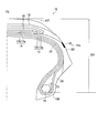
- FIG. 1 is a diagram showing an example of the configuration of a pneumatic tire 10 (hereinafter, simply referred to as a tire 10) of one embodiment.
- FIG. 1 shows a tire profile cross section on one side in the tire width direction with respect to the tire equatorial line CL.
- the tire 10 is provided on both sides of a tread portion 10T having a tread pattern, a pair of bead portions 10B on both sides in the tire width direction, and a pair of side portions connected to the pair of bead portions 10B and the tread portion 10T.
- a wall portion 10S is provided.
- the tread portion 10T is a portion that comes into contact with the road surface.
- the sidewall portion 10S is a portion provided so as to sandwich the tread portion 10T from both sides in the tire width direction.
- the bead portion 10B is a portion connected to the sidewall portion 10S and located inside the sidewall portion 10S in the tire radial direction.
- the tire 10 has a carcass ply 12, a belt 14, and a bead core 16 as skeleton materials, and around these skeleton materials, a tread rubber member 18, a side rubber member 20, and a bead filler rubber member 22 are provided. , A rim cushion rubber member 24 and an inner liner rubber member 26 are mainly provided.
- the carcass ply 12 is composed of carcass ply materials 12a and 12b in which organic fibers are coated with rubber, which are wound around a pair of annular bead cores 16 to form a toroidal shape.
- the carcass ply 12 is wound around the bead core 16 and extends outward in the tire radial direction.
- the carcass ply 12 is composed of two layers of carcass ply materials 12a and 12b.
- the carcass ply material 12a is wound around the bead core 16 and extends outward in the tire radial direction, extends to the inside of the belt 14 described below in the tire radial direction, and the carcass ply material 12b is wound around the bead core 16.
- a belt 14 composed of two belt members 14a and 14b is provided on the outside of the carcass ply 12 in the tire radial direction.
- the belt 14 is composed of a member in which rubber is coated on a steel cord arranged at a predetermined angle, for example, 20 to 30 degrees with respect to the tire circumferential direction, and the width of the lower belt material 14a in the tire width direction is It is wider than the width of the upper belt material 14b in the tire width direction.
- the inclination directions of the steel cords of the two-layer belt members 14a and 14b are opposite to each other. Therefore, the belt materials 14a and 14b are interlaced layers, and suppress the expansion of the carcass ply 12 due to the filled air pressure.
- a tread rubber member 18 is provided on the outer side of the belt 14 in the tire radial direction, and side rubber members 20 are connected to both ends of the tread rubber member 18 to form a sidewall portion 10S.
- a rim cushion rubber member 24 is provided at the inner end of the side rubber member 20 in the tire radial direction and comes into contact with the rim on which the tire 10 is mounted.
- the outside of the bead core 16 in the tire radial direction is sandwiched between the part of the carcass ply 12 before being wound around the bead core 16 and the part of the carcass ply 12 after being wound around the bead core 16.
- a bead filler rubber member 22 is provided.
- An inner liner rubber member 26 is provided on the inner surface of the tire 10 facing the air-filled tire cavity region surrounded by the tire 10 and the rim.
- the tread rubber member 18 shown in FIG. 1 includes a cap tread rubber member on the outer side in the tire radial direction and a base tread rubber member on the inner side in the tire radial direction.
- a two-layer belt cover 30 coated with rubber of organic fibers that covers the belt 14 from the outside in the tire radial direction of the belt 14 is provided between the belt material 14b and the tread rubber member 18.
- the belt cover 30 may be provided as needed and is not essential.
- the number of layers of the belt cover 30 is not limited to two, and may be one or three.
- a two-dimensional code 40 is provided on the surface of the sidewall portion 10S of the tire 10. In FIG. 1, the two-dimensional code 40 is drawn with a thick line.
- FIG. 2 is a diagram showing an example of a two-dimensional code 40 provided on the tire 10 of one embodiment.
- the two-dimensional code 40 is provided on the smooth surface 56.
- the smooth surface 56 is, for example, a surface having an arithmetic mean roughness Ra (JIS B 0601: 2001) of 10 ⁇ m to 100 ⁇ m.
- Such a two-dimensional code 40 is formed on both surfaces of the sidewall portions 10S on both sides in the tire width direction. According to another embodiment, it is formed on the surface of either sidewall portion 10S.
- the two-dimensional code 40 is a dot pattern formed by two types of shading elements formed so as to be distinguishable from each other by the unevenness of the surface.
- the two-dimensional code 40 of one embodiment is formed by concentrating laser light on the surface of the sidewall portion 10S, concentrating energy, locally heating and incinerating the side rubber member 20, and providing a plurality of minute dot holes on the surface. It is a pattern that has been made.
- the dot hole is, for example, a conical hole, the diameter on the surface is, for example, 0.1 to 1.0 mm, and the depth is, for example, 0.3 to 1.0 mm.
- the two-dimensional code 40 is configured by providing one dot hole (recess) in one unit cell region of the dark region among the unit cells that divide the light and shade elements of the two-dimensional code. That is, in the two-dimensional code 40, the dot holes are arranged so that one dot hole forms one unit cell region having a dark shade element in a plurality of unit cell regions having a rectangular shape of the same size divided in a grid pattern. Has a configured configuration. In FIG. 2, the dark area of the unit cell area is indicated by a black-filled area.
- the two-dimensional code 40 shown in FIG. 2 is a QR code (registered trademark) and includes a dot pattern region 42 in which a dot pattern is formed by two types of shading elements.
- a blank area 44 surrounded by the same light element as the light element among the light and shade elements is provided around the dot pattern area 42.
- the blank area 44 is indicated by an area between the rectangular frame surrounded by the alternate long and short dash line in FIG. 2 and the edge of the dot pattern area 42.
- the blank area 44 is an area that is regarded as a quiet zone in the QR code (registered trademark), and is an area required for reading the QR code (registered trademark).
- the blank area 44 surrounds the dot pattern area 42 is, for example, a unit in the dot pattern area 42. It is preferably 4 to 5 times the size of the cell region.
- the width of the blank area 44 is preferably 4% to 25% of the maximum size of the rectangular shape of the dot pattern area 42 in two directions.
- the two-dimensional code 40 shown in FIG. 2 is a QR code (registered trademark)
- the dot pattern area 42 includes a data cell area displaying a data cell of the QR code (registered trademark) and a cutout symbol area displaying a cutout symbol. And include.
- the two-dimensional code 40 is provided on the smooth surface 56, the readability is improved as compared with the case where the two-dimensional code 40 is provided in the ridge pattern region.
- the tire 10 provided with the two-dimensional code 40 is a tire having a tire cross-sectional height SH of 80 mm or less along the tire radial direction from the innermost position in the tire radial direction of the bead core 16 to the maximum outer diameter position of the tire.
- the ratio of the tire cross-sectional height SH to the maximum tire width in which the tire width in the tire width direction of the tire 10 is maximum is, for example, a low flat tire having a flatness ratio of 0.4 or less (flatness of 40% or less).
- the area of the sidewall portion 10S is small, and the ridge pattern region often occupies most of the sidewall portion 10S.
- the smooth surface 56 on which the two-dimensional code 40 can be provided is limited to the buttress region near the pattern end of the sidewall portion 10S. As described above, this part is a part where a vulcanization failure is likely to occur, and if a two-dimensional code 40 is provided at a place where the vulcanization failure occurs, even if the degree of the vulcanization failure is weak, the tire 10 can be used for a long period of time. The decrease in readability of the dimension code 40 tends to be large.
- the first ridge 60 described below is described in order to suppress the occurrence of a vulcanization failure in the area where the two-dimensional code 40 is planned to be arranged. Is provided near the planned placement area.
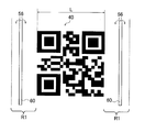
- FIG. 3 is a diagram showing an example of the arrangement of the two-dimensional code 40 and the first ridge 60 provided on the tire 10 of one embodiment.
- the width of the two-dimensional code 40 along the tire circumferential direction is L, and the position is separated from both edges of the two-dimensional code 40 in the tire circumferential direction by 50% of the width L along the tire circumferential direction.
- At least one first ridge 60 projecting from the smooth surface 56 and extending in the tire radial direction is provided on the surface of the tire 10 within the range R1 between (the position of the dotted line in FIG. 3) and the edge. ..
- the portion of the range R1 other than the first ridge 60 is a smooth surface 56.
- one first ridge 60 is provided on both sides of the two-dimensional code 40 in the tire circumferential direction, but one is provided only on one side of the two-dimensional code 40 in the tire circumferential direction.
- the first ridge 60 may be provided. If the first ridge 60 is provided outside the range R1, the occurrence of vulcanization failure in the planned arrangement region of the two-dimensional code 40 cannot be sufficiently suppressed.
- the arrangement range in the tire radial direction in which the first ridge 60 is arranged preferably includes the arrangement range in the tire radial direction in which the two-dimensional code 40 is arranged. Further, the number of first ridges provided in one of the range R1 is preferably 2 or less.
- the first ridge 60 is provided in the range R1, but as described above, in order to secure the blank area 44 (see FIG. 2), the two-dimensional code is at least the width of the blank area 44 described above. It is provided apart from the edge of 40.
- one or a plurality of first ridges 60 extending in the tire radial direction are provided on the surface within the range R1 with respect to the two-dimensional code 40, and the portion other than the first ridge 60 is a smooth surface 56.
- the surface of the smooth surface 56 within the range R1 with respect to the planned placement area of the two-dimensional code 40 is formed.
- One or a plurality of first ridges 60 extending in the tire radial direction are provided, and the portion other than the first ridge 60 is a smooth surface 56.
- the plurality of first ridges 60 are different from the ridges in the ridge pattern in which three or more ridges are continuously arranged at equal intervals.
- the first ridge 60 is formed by a groove corresponding to the first ridge 60 on the inner surface of the vulcanization die. Therefore, when the raw tire is expanded and brought into contact with the vulcanization mold for vulcanization, the gas in the gap between the raw tire and the inner surface in the planned arrangement area of the two-dimensional code 40 is vulcanized. Since it can flow into the groove provided on the inner surface of the mold, it is possible to suppress the occurrence of vulcanization failure in the planned arrangement region.
- the contact range of the raw tire gradually expands from the position where the contact starts to the direction corresponding to the tire radial direction. Therefore, by providing the groove in the direction corresponding to the tire radial direction, the gas in the gap between the raw tire and the inner surface can be efficiently flowed into the groove.
- one first ridge 60 is provided on each side of the two-dimensional code 40 in the tire circumferential direction, and the two first ridges 60 are provided with each other. It is preferable that the two first ridges 60 are parallel to each other, and the distance from each of the two first ridges 60 to the nearest edge of the two-dimensional code 40 with respect to each of the first ridges 60 is preferably the same. ..
- the flow of gas between the raw tire and the inner surface of the vulcanization mold in the area where the two-dimensional code 40 is planned to be arranged is transferred to the tire in the area where the two-dimensional code 40 is planned to be arranged. It can be formed in the same manner on both sides in the circumferential direction to reduce the bias of the occurrence of vulcanization failure.
- the height of protrusion of the first ridge 60 from the smooth surface 56 is preferably 0.3 to 1.0 mm.
- the protrusion height is less than 0.3 mm, the effect of allowing gas to flow into the groove from the planned arrangement region of the two-dimensional code 40 is small, and the occurrence of vulcanization failure cannot be sufficiently suppressed.
- the protruding height is larger than 1.0 mm, the rubber flow caused by the groove cannot be ignored during vulcanization, and poor appearance is likely to occur.
- the protruding height is more preferably 0.4 to 0.8 mm, for example.
- the width of the first ridge 60 is not particularly limited, but is, for example, 0.5 mm to 4.0 mm.
- the width is less than 0.5 mm, the effect of allowing gas to flow into the groove from the area where the two-dimensional code 40 is planned to be arranged is small, and the occurrence of vulcanization failure cannot be sufficiently suppressed.
- the width is larger than 4.0 mm, the rubber flow caused by the groove during vulcanization cannot be ignored, and poor appearance is likely to occur.
- FIG. 4 is a diagram showing another example of the arrangement of the two-dimensional code 40 and the first ridge 60 provided on the tire 10 of one embodiment.
- Two first ridges 60 are provided on both sides of the two-dimensional code 40 shown in FIG. 4 in the tire circumferential direction, and the ends of the two first ridges 60 on both sides in the tire radial direction are connected.
- Two second ridges 62 extending in the tire circumferential direction are provided.
- the two-dimensional code 40 is surrounded by the first ridge 60 and the second ridge 62 from four directions.
- the two second ridges 62 are also preferably parallel to each other, and further, the closest of the two-dimensional code 40 to each of the first ridges 60 of each of the second ridges 62 in Japan.
- the distances to the edges are the same as each other.
- the two first ridges 60 are parallel to each other, the two second ridges 62 are also parallel to each other, and each of the two first ridges 60 is parallel to the first ridge 60, respectively.
- the first distance to the nearest edge of the two-dimensional code 40 is the same as each other, and the closest edge of the two-dimensional code 40 to each of the two second ridges 62 and each of the second ridges 62.
- the second separation distances up to are the same as each other.
- the tire in the area where the gas flow between the raw tire and the inner surface of the vulcanization die in the area where the two-dimensional code 40 is planned to be arranged is to be arranged. It can be formed in the same manner on both sides in the circumferential direction and the tire radial direction to reduce the bias of occurrence of vulcanization failure. In this case, it is particularly preferable that the first separation distance and the second separation distance are the same.
- the gas flow between the raw tire and the inner surface of the vulcanization die can be made uniform, and the occurrence of vulcanization failure can be further suppressed.
- the second ridge 62 is provided on the outer side and the inner side in the tire radial direction with respect to the two-dimensional code 40, when the raw tire is expanded and brought into contact with the vulcanization mold for vulcanization, the second ridge is formed. Since the gas in the gap between the raw tire and the inner surface of the vulcanization mold in the area where the dimension code 40 is to be arranged can flow into the groove provided on the inner surface of the vulcanization mold. , The degree of suppressing the occurrence of vulcanization failure in the planned placement area will increase.
- the protruding height of the second ridge 62 from the smooth surface 56 is preferably 0.3 to 1.0 mm for the same reason as that of the first ridge 60.
- the protruding height of the second ridge 62 is more preferably 0.4 to 0.8 mm, for example.
- the second ridge 62 has a length along the surface of the sidewall portion 10S between the outer edge in the tire radial direction and the inner edge in the tire radial direction of the two-dimensional code 40. Only 50% of the length is provided within the range R2 (see FIG. 4) between a position separated from each edge of the two-dimensional code 40 on both sides in the tire radial direction along the tire radial direction and the edge. Is preferable.
- the second ridge 62 By providing the second ridge 62 within the range R2, it is possible to further suppress the occurrence of vulcanization failure in the region where the two-dimensional code 40 is planned to be arranged.
- the second ridge 62 is provided in the range R2, but as described above, in order to secure the blank area 44 (see FIG. 2), the two-dimensional code is at least the width of the blank area 44 described above. Separate from the edge of 40.
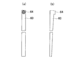
- FIG. 5A is a diagram illustrating an example of one end of the first ridge 60.
- a protrusion mark 64 for a vent hole is provided at one end of the first ridge 60 in the tire radial direction.
- the protrusion mark 64 for the vent hole is a portion slightly protruding from the top of the first ridge 60.
- the vent hole protrusion mark 64 is a mark after cutting the vent hole protrusion formed on the tire 10 immediately after vulcanization in the vicinity of the protrusion base portion.
- the vent hole is a gas discharge hole provided in the vulcanization die, and has a function of discharging the gas between the raw tire and the inner surface of the vulcanization die to the outside of the vulcanization die.
- the vent hole protrusion is a whisker-shaped protrusion formed by flowing excess rubber or the like into the vent hole, which is a gas discharge hole, after the gas is discharged to the outside, and is also called a spew. Therefore, the protrusion mark 64 for the vent hole means that the vent hole is provided at the groove bottom at the end of the groove corresponding to the first ridge 60 in the vulcanization die. Therefore, in such a vulcanization die, the gas in the area where the two-dimensional code 40 is planned to be arranged and between the raw tire and the inner surface of the vulcanization die is passed through the vent hole of the vulcanization die.
- the protrusion marks 64 for the vent hole may be provided at both ends of the first ridge 60.
- the outer diameter of the protrusion mark 64 for the vent hole is preferably 2.0 to 4.0 mm, for example.
- FIG. 5B is a diagram illustrating an example of one end of the first ridge 60.
- the vent hole it is preferable that the protrusion marks 64 are provided at the ends of the first ridge 60 on both sides in the tire radial direction, whichever has the higher protrusion height.
- the groove depth of the groove provided in the vulcanization die corresponding to the first ridge 60 gradually becomes deeper along the direction corresponding to the tire radial direction. It means that a vent hole is provided at the end of the deeper groove depth.
- the gas flowing into the groove is allowed to flow toward the end side having a deep groove depth, and the vent hole provided on this end side is sent to the outside of the vulcanization die. Since it can be discharged, the frequency of vulcanization failures in the area where the two-dimensional code 40 is planned to be arranged can be further reduced.
- the difference in protrusion height between one end of the first ridge 60 and the other end is, for example, 0.2 to 0.5 mm.
- the protrusion height may change linearly or curvedly.
- FIG. 6 is a diagram illustrating an example of arrangement of the two-dimensional code 40 provided on the tire 10 of one embodiment.
- the smooth surface 56 on which the planned arrangement area of the two-dimensional code 40 is set is small in the sidewall portion 10S and is limited to the buttress area.
- the buttress region has a boundary portion between the tread rubber member 18 and the side rubber member 20. As described above, this boundary portion often has a step that easily induces a vulcanization failure in the raw tire.
- the planned arrangement area of the two-dimensional code 40 is set so as to straddle the boundary portion. Even if it is, it is possible to suppress the occurrence of vulcanization failure in this planned arrangement area.
- the reading of the two-dimensional code 40 was performed with a two-dimensional code reader.
- a predetermined illumination light is applied to the two-dimensional code 40 from a predetermined direction (10 directions) to read the two-dimensional code 40 of 10 tires, and the ratio of the number of times correctly read to the number of times the two-dimensional code 40 is read is read.
- the success rate of. In each case, the obtained reading success rate was lower than the reading success rate at the start of use of the tire, but among the reduced success rates, the reading success rate of the comparative example in which the first ridge 60 was not provided. was set to 100, and the reading success rate of each example was indexed to obtain the evaluation result of readability during long-term use of the tire. The evaluation results are shown in Tables 1 and 2 below.
- the two-dimensional code 40 is engraved with a QR code (registered trademark) having a dot hole depth of 1.5 mm and a square unit cell length of 0.6 mm for dividing the shading elements. did.
- the protruding height of the first ridge 60 and the second ridge 62 was 0.5 mm or 0.3 to 0.8 mm, and the width of the first ridge 60 and the second ridge 62 was 0.6 mm.
- the outer diameter of the protrusion mark 64 for the vent hole was set to 0.5 mm.
- the center position of the width of the first ridge 60 is located at a position away from the edge of the two-dimensional code 40 by 30% of the width of the two-dimensional code 40 in the tire circumferential direction from the edge of the two-dimensional code 40.
- the second ridge 62 is provided, only 30% of the length along the surface of the sidewall portion 10S between the outer edge of the second ridge 62 in the tire radial direction and the inner edge in the tire radial direction is two-dimensional.
- the center position of the width of the second ridge 62 is provided at a position away from the edge of the cord 40.
- “on one side” means that the first ridge 60 is provided on one side of the two-dimensional code 40 in the tire circumferential direction
- “on both sides” means that the first ridge 60 is provided. It means that the two-dimensional code 40 is provided on both sides in the tire circumferential direction.
- “existing on the outside in the tire radial direction” means that the second ridge 62 is provided on the outside in the tire radial direction of the two-dimensional code 40
- “existing on the inside and outside in the tire radial direction” means that the second ridge 62 is provided on the outside in the tire radial direction. It means that 62 is provided inside and outside the tire radial direction of the two-dimensional code 40.
- “At one end” in Example 6 means that the protrusion mark 64 for a vent hole is provided at the end on the side having a high protrusion height.
- the protruding height of the outer end in the tire radial direction was made higher than the protruding height of the inner end.
- the protrusion height of the first ridge 60 is constant, and the protrusion mark 64 for the vent hole is provided at the outer end in the tire radial direction.
- the readability was lower than the readability at the start of use of the tire, but from Table 1, by providing at least one first ridge 60 within the range R1, during long-term use of the tire. It can be seen that the decrease in readability of the two-dimensional code 40 is suppressed as compared with the case where the first ridge 60 is not provided.
Landscapes
- Engineering & Computer Science (AREA)
- Mechanical Engineering (AREA)
- Tires In General (AREA)
Abstract
空気入りタイヤのサイドウォール部の表面は、スムース面の領域と、該領域内にあり、前記スムース面に対して表面凹凸によって互いに識別可能に形成された2種類の濃淡要素でドットパターンが形成された二次元コードと、を備える。前記空気入りタイヤの、ビードコアのタイヤ径方向の最も内側の位置からタイヤ最大外径位置までのタイヤ径方向に沿ったタイヤ断面高さSHは80mm以下であり、前記二次元コードの前記タイヤ周方向に沿った幅の50%の長さ、前記二次元コードのタイヤ周方向の両側それぞれの縁から前記タイヤ周方向に沿って離れた位置と当該縁との間の範囲内の前記空気入りタイヤの表面には、前記スムース面に対して突出してタイヤ径方向に延びる第1リッジが少なくとも1本設けられ、前記第1リッジ以外の部分は、前記スムース面である。
Description
本発明は、空気入りタイヤに関し、具体的には、タイヤの側面に二次元コードを備える空気入りタイヤに関する。
近年、空気入りタイヤ(以降、単にタイヤともいう)の側面(サイドウォール部)に、情報を記録した二次元コードを設けることが提案されている。二次元コードは、一次元コードに比べて多くの情報を含ませることができるので、種々の情報を二次元コードに含ませて、タイヤを管理することができる。サイドウォール部に、ドット孔で所定のパターンを刻印することにより、濃淡要素のパターンで構成された二次元コードをサイドウォール部に設けることが提案されている(特許文献1)。
このような二次元コードの複数のドット孔を設けた空気入りタイヤは、新品時において二次元コードの読み取りは可能であるが、屋外の環境下、荷重を負荷して転動した場合に二次元コードの読み取りが低下する場合があった。二次元コードの読み取りとは、二次元コード読み取り器、例えば、携帯端末等による二次元コードの読み取りであり、読み取りの低下とは、読み取りを失敗する場合が多くなることをいう。空気入りタイヤに設けられる二次元コードは、タイヤの使用中に二次元コードに記録された情報を読み取って活用することが行われる。このため、タイヤを長期使用したとき、二次元コードのドット孔におけるクラックの発生と進展によって二次元コードの表面に凹凸が発生し、濃淡要素の区別が困難になり二次元コードの読み取り性が低下することは好ましくない。このため、タイヤの長期使用の際に二次元コードの読み取り性の低下が抑制されることが好ましい。
このような二次元コードは、空気入りタイヤの使用初期段階において、二次元コードの濃淡要素が明確に区別でき、高い読み取り性を有するために、サイドウォール部のスムース面に設けられることが好ましい。スムース面は、表面凹凸による模様やリッジ模様が設けられない、平滑な面である。リッジ模様とは、線状に延びる突出高さ0.2mm以上のリッジを一定の間隔で設けることにより形成される模様である。
ところで、タイヤ断面高さが80mm以下の空気入りタイヤでは、サイドウォール部の表面の面積が小さいため、二次元コードを配置する程度の広さを有するスムース面は少なく、スムース面は、トレッドパターンエンドからサイドウォール部のタイヤ径方向上方にあるバットレス領域に制限される。このため、タイヤ断面高さが80mm以下の空気入りタイヤでは、バットレス領域のスムース面に二次元コードは設けられる。
しかし、このバットレス領域には、トレッドゴム部材とサイドゴム部材との境界部分があり、この境界部分には、生タイヤにおいて僅かな段差が生じる場合が多く、この段差によって、加硫故障が生じ易い。加硫故障は、生タイヤを拡張させて加熱した加硫金型の内表面に押し付けるとき、加硫金型の内表面と生タイヤとの間にある気体の排出が十分にできず気体が残り、この気体が、高温に制御された加硫金型の内表面と生タイヤとの接触を阻害して生タイヤの加硫を十分にさせないことにより生じる。したがって、段差のある上記境界部分では、上記気体が残り加硫故障が発生する場合が多い。この加硫故障には、加硫終了後のタイヤの表面において光沢のある面となって目視検査で容易に判別できるものもあれば、加硫故障の程度が弱いため、目視検査では判別が困難な加硫故障もある。
したがって、目視検査により加硫故障の発生しているタイヤを排除しても、加硫故障したタイヤをすべて排除することはできない。このため、目視検査で判別できない、程度の弱い加硫故障の発生部分に二次元コードを設ける場合もある。程度の弱い加硫故障であっても、この加硫故障の発生した部分に二次元コードを設けると、加硫が十分でないことに起因して、タイヤの長期使用によって二次元コードのドット孔周りに発生するクラックが多くなる。このクラックの発生は、加硫故障の無い部分に二次元コードを設ける場合に比べて多い。このため二次元コードの表面凹凸が変化して二次元コードの読み取り性は低下し易い。
このように二次元コードを設ける領域に加硫故障があることは好ましくない。
したがって、目視検査により加硫故障の発生しているタイヤを排除しても、加硫故障したタイヤをすべて排除することはできない。このため、目視検査で判別できない、程度の弱い加硫故障の発生部分に二次元コードを設ける場合もある。程度の弱い加硫故障であっても、この加硫故障の発生した部分に二次元コードを設けると、加硫が十分でないことに起因して、タイヤの長期使用によって二次元コードのドット孔周りに発生するクラックが多くなる。このクラックの発生は、加硫故障の無い部分に二次元コードを設ける場合に比べて多い。このため二次元コードの表面凹凸が変化して二次元コードの読み取り性は低下し易い。
このように二次元コードを設ける領域に加硫故障があることは好ましくない。
そこで、本発明は、二次元コードが設けられる領域に加硫故障が発生することを抑制し、これにより、タイヤを長期使用しても、二次元コードの読み取り性の低下を抑制することができる空気入りタイヤを提供することを目的とする。
本発明の一態様は、空気入りタイヤである。当該空気入りタイヤは、
円環状の一対のビードコアと、
前記一対のビードコアの周りに巻きまわして前記一対のビードコア間に設けられた、トロイダル状のカーカスプライと、
前記カーカスプライをタイヤ幅方向の外側から覆うように前記空気入りタイヤのサイドウォール部のそれぞれに設けられた一対のサイドゴム部材と、を備え、
前記サイドウォール部の少なくとも一方の表面は、スムース面の領域と、該領域内にあり、前記スムース面に対して表面凹凸によって互いに識別可能に形成された2種類の濃淡要素でドットパターンが形成された二次元コードと、を備え、
前記空気入りタイヤの、前記ビードコアのタイヤ径方向の最も内側の位置からタイヤ最大外径位置までの前記タイヤ径方向に沿った断面高さは80mm以下であり、
前記二次元コードの前記空気入りタイヤのタイヤ周方向に沿った幅の50%の長さ、前記二次元コードの前記タイヤ周方向の両側それぞれの縁から前記タイヤ周方向に沿って離れた位置と該縁との間の範囲内の前記空気入りタイヤの表面には、前記スムース面に対して突出して前記タイヤ径方向に延びる1本または複数本の第1リッジが設けられ、前記範囲内の前記第1リッジ以外の部分は、前記スムース面である。
円環状の一対のビードコアと、
前記一対のビードコアの周りに巻きまわして前記一対のビードコア間に設けられた、トロイダル状のカーカスプライと、
前記カーカスプライをタイヤ幅方向の外側から覆うように前記空気入りタイヤのサイドウォール部のそれぞれに設けられた一対のサイドゴム部材と、を備え、
前記サイドウォール部の少なくとも一方の表面は、スムース面の領域と、該領域内にあり、前記スムース面に対して表面凹凸によって互いに識別可能に形成された2種類の濃淡要素でドットパターンが形成された二次元コードと、を備え、
前記空気入りタイヤの、前記ビードコアのタイヤ径方向の最も内側の位置からタイヤ最大外径位置までの前記タイヤ径方向に沿った断面高さは80mm以下であり、
前記二次元コードの前記空気入りタイヤのタイヤ周方向に沿った幅の50%の長さ、前記二次元コードの前記タイヤ周方向の両側それぞれの縁から前記タイヤ周方向に沿って離れた位置と該縁との間の範囲内の前記空気入りタイヤの表面には、前記スムース面に対して突出して前記タイヤ径方向に延びる1本または複数本の第1リッジが設けられ、前記範囲内の前記第1リッジ以外の部分は、前記スムース面である。
前記第1リッジは2本の第1リッジであり、前記二次元コードの前記タイヤ周方向の両側のそれぞれに前記2本の第1リッジの1つが設けられ、前記2本の第1リッジは互いに平行である、ことが好ましい。
前記2本の第1リッジそれぞれの、前記2本の第1リッジそれぞれに対して前記二次元コードの最も近い縁までの離間距離は、互いに同じである、ことが好ましい。
前記第1リッジの前記スムース面からの突出高さは、0.3~1.0mmである、ことが好ましい。前記突出高さは、より好ましくは、0.4~0.8mmである。
前記第1リッジは2本の第1リッジであり、前記二次元コードの前記タイヤ周方向の両側のそれぞれに前記2本の第1リッジの1つが設けられ、さらに、前記2本の第1リッジの前記タイヤ径方向の両側の端のそれぞれを接続する、前記タイヤ周方向に延びる2本の第2リッジが設けられ、
前記2本の第1リッジと前記2本の第2リッジにより、前記二次元コードは囲まれている、ことが好ましい。
前記2本の第1リッジは、互いに平行である、ことが好ましい。
前記2本の第1リッジそれぞれの、前記2本の第1リッジそれぞれに対して前記二次元コードの最も近い縁までの第1離間距離は、互いに同じである、ことが好ましい。
前記2本の第2リッジそれぞれの、前記2本の第2リッジそれぞれに対して前記二次元コードの最も近い縁までの第2離間距離は、互いに同じである、ことが好ましい。
前記2本の第2リッジそれぞれの、前記2本の第2リッジそれぞれに対して前記二次元コードの最も近い縁までの第2離間距離は、互いに同じであり、前記第1離間距離と前記第2離間距離は、同じである、ことが好ましい。
前記2本の第1リッジそれぞれの、前記2本の第1リッジそれぞれに対して前記二次元コードの最も近い縁までの離間距離は、互いに同じである、ことが好ましい。
前記第1リッジの前記スムース面からの突出高さは、0.3~1.0mmである、ことが好ましい。前記突出高さは、より好ましくは、0.4~0.8mmである。
前記第1リッジは2本の第1リッジであり、前記二次元コードの前記タイヤ周方向の両側のそれぞれに前記2本の第1リッジの1つが設けられ、さらに、前記2本の第1リッジの前記タイヤ径方向の両側の端のそれぞれを接続する、前記タイヤ周方向に延びる2本の第2リッジが設けられ、
前記2本の第1リッジと前記2本の第2リッジにより、前記二次元コードは囲まれている、ことが好ましい。
前記2本の第1リッジは、互いに平行である、ことが好ましい。
前記2本の第1リッジそれぞれの、前記2本の第1リッジそれぞれに対して前記二次元コードの最も近い縁までの第1離間距離は、互いに同じである、ことが好ましい。
前記2本の第2リッジそれぞれの、前記2本の第2リッジそれぞれに対して前記二次元コードの最も近い縁までの第2離間距離は、互いに同じである、ことが好ましい。
前記2本の第2リッジそれぞれの、前記2本の第2リッジそれぞれに対して前記二次元コードの最も近い縁までの第2離間距離は、互いに同じであり、前記第1離間距離と前記第2離間距離は、同じである、ことが好ましい。
前記2本の第2リッジは、前記二次元コードの、前記タイヤ径方向の外側の縁と前記タイヤ径方向の内側の縁との間の前記サイドウォール部の表面に沿った長さの50%の長さだけ、前記二次元コードの前記タイヤ径方向の両側それぞれの縁から前記タイヤ径方向に沿って離れた位置と該縁との間の範囲内に設けられる、ことが好ましい。
前記第1リッジの前記タイヤ径方向における端には、ベントホール用突起痕が設けられている、ことが好ましい。
前記第1リッジの、前記スムース面に対する突出高さは、前記第1リッジの一方の端から前記タイヤ径方向に沿って徐々に高くなり、前記ベントホール用突起痕は、前記第1リッジの前記タイヤ径方向の両側の端のうち、前記突出高さの高い方の端に設けられている、ことが好ましい。
前記第1リッジの一方の端と他方の端との間の突出高さの差は、0.2~0.5mmである、ことが好ましい。
前記第1リッジの一方の端と他方の端との間の突出高さの差は、0.2~0.5mmである、ことが好ましい。
前記第1リッジは、前記一対のサイドゴム部材の1つと、前記空気入りタイヤのトレッドゴム部材との境界を跨ぐように設けられていてもよい。
前記第2リッジの前記スムース面からの突出高さは、0.3~1.0mmである、ことが好ましい。前記突出高さは、より好ましくは、0.4~0.8mmである。
前記範囲内に設けられる前記第1リッジの個数は2つ以下である、ことが好ましい。
前記第2リッジの前記スムース面からの突出高さは、0.3~1.0mmである、ことが好ましい。前記突出高さは、より好ましくは、0.4~0.8mmである。
前記範囲内に設けられる前記第1リッジの個数は2つ以下である、ことが好ましい。
以下、実施形態の空気入りタイヤについて詳細に説明する。
本明細書において、タイヤ幅方向は、空気入りタイヤの回転軸と平行な方向である。タイヤ幅方向の外側は、タイヤ幅方向において、タイヤ赤道面を表すタイヤ赤道線CL(図1参照)から離れる側である。また、タイヤ幅方向の内側は、タイヤ幅方向において、タイヤ赤道線CLに近づく側である。タイヤ周方向は、空気入りタイヤの回転軸を回転の中心として回転する方向である。タイヤ径方向は、空気入りタイヤの回転軸に直交する方向である。タイヤ径方向の外側は、前記回転軸から離れる側をいう。また、タイヤ径方向の内側は、前記回転軸に近づく側をいう。
本明細書で後述するタイヤ断面高さSH及びタイヤ最大幅は、タイヤを規定リムに組んで、規定内圧を加えた無負荷状態において測定される寸法をいう。ここで、規定リムとは、タイヤがJATAMAに準拠する場合、JATMAに規定される「適用リム」、タイヤがTRAに準拠する場合、TRAに規定される「Design Rim」、又はタイヤがETRTOに準拠する場合、ETRTOに規定される「Measuring Rim」をいう。また、規定内圧とは、JATMAに規定される「最高空気圧」、TRAに規定される「TIRE LOAD LIMITS AT VARIOUS COLD INFLATION PRESSURES」の最大値、又はETRTOに規定される「INFLATION PRESSURES」をいう。
なお、以下に説明する実施形態の空気入りタイヤの側面(サイドウォール部)には二次元コードが設けられている。二次元コードは、例えば刻印により設けられる。刻印は、レーザ光をサイドウォール部の表面で集束させてエネルギを集中しサイドウォール部のゴムを局所的に加熱焼却して表面に微小なドット孔を複数形成する態様の他、ゴムに別の手段で凹凸を形成して二次元コードを形成する態様を含む。
実施形態で言う二次元コードは、横方向にしか情報を持たない一次元コード(バーコード)とは異なり、二方向に情報を持つマトリックス表示方式のコードである。二次元コードとして、例えば、QRコード(登録商標)、データマトリクス(登録商標)、Maxicode、PDF-417(登録商標)、16Kコード(登録商標)、49コード(登録商標)、Aztecコード(登録商標)、SPコード(登録商標)、ベリコード(登録商標)、及び、CPコード(登録商標)を含む。
(空気入りタイヤ)
図1は、一実施形態の空気入りタイヤ10(以降、単にタイヤ10という)の構成の一例を示す図である。図1は、タイヤ赤道線CLに対してタイヤ幅方向の一方の側のタイヤプロファイル断面を示す。
図1は、一実施形態の空気入りタイヤ10(以降、単にタイヤ10という)の構成の一例を示す図である。図1は、タイヤ赤道線CLに対してタイヤ幅方向の一方の側のタイヤプロファイル断面を示す。
タイヤ10は、トレッドパターンを有するトレッド部10Tと、タイヤ幅方向両側の一対のビード部10Bと、トレッド部10Tの両側に設けられ、一対のビード部10Bとトレッド部10Tに接続される一対のサイドウォール部10Sと、を備える。トレッド部10Tは路面と接触する部分である。サイドウォール部10Sは、トレッド部10Tをタイヤ幅方向の両側から挟むように設けられた部分である。ビード部10Bは、サイドウォール部10Sに接続され、サイドウォール部10Sに対してタイヤ径方向の内側に位置する部分である。
タイヤ10は、骨格材として、カーカスプライ12と、ベルト14と、ビードコア16と、を有し、これらの骨格材の周りに、トレッドゴム部材18と、サイドゴム部材20と、ビードフィラーゴム部材22と、リムクッションゴム部材24と、インナーライナゴム部材26と、を主に有する。
カーカスプライ12は、一対の円環状のビードコア16の間を巻きまわしてトロイダル形状を成した、有機繊維をゴムで被覆したカーカスプライ材12a,12bで構成されている。カーカスプライ12は、ビードコア16の周りに巻きまわされてタイヤ径方向の外側に延びている。カーカスプライ12は、2層のカーカスプライ材12a,12bで構成される。カーカスプライ材12aは、ビードコア16の周りに巻きまわされてタイヤ径方向の外側に延び、下記に説明するベルト14のタイヤ径方向の内側まで延び、カーカスプライ材12bは、ビードコア16の周りに巻きまわされて、以降で説明するビードフィラーゴム部材22に接する状態で終端している。カーカスプライ12のタイヤ径方向の外側に2枚のベルト材14a,14bで構成されるベルト14が設けられている。ベルト14は、タイヤ周方向に対して、所定の角度、例えば20~30度傾斜して配されたスチールコードにゴムを被覆した部材で構成され、下層のベルト材14aのタイヤ幅方向の幅が上層のベルト材14bのタイヤ幅方向の幅に比べて広い。2層のベルト材14a,14bのスチールコードの傾斜方向は互いに逆方向である。このため、ベルト材14a,14bは、交錯層となっており、充填された空気圧によるカーカスプライ12の膨張を抑制する。
ベルト14のタイヤ径方向の外側には、トレッドゴム部材18が設けられ、トレッドゴム部材18の両端部には、サイドゴム部材20が接続されてサイドウォール部10Sを形成している。サイドゴム部材20のタイヤ径方向の内側の端には、リムクッションゴム部材24が設けられ、タイヤ10を装着するリムと接触する。ビードコア16のタイヤ径方向の外側には、ビードコア16の周りに巻きまわす前のカーカスプライ12の部分と、ビードコア16の周りに巻きまわした後のカーカスプライ12の部分との間に挟まれるようにビードフィラーゴム部材22が設けられている。タイヤ10とリムとで囲まれる空気を充填するタイヤ空洞領域に面するタイヤ10の内表面には、インナーライナゴム部材26が設けられている。
なお、図1に示すトレッドゴム部材18は、タイヤ径方向の外側にあるキャップトレッドゴム部材と、タイヤ径方向の内側にあるベーストレッドゴム部材とを備える。
なお、図1に示すトレッドゴム部材18は、タイヤ径方向の外側にあるキャップトレッドゴム部材と、タイヤ径方向の内側にあるベーストレッドゴム部材とを備える。
この他に、ベルト材14bとトレッドゴム部材18との間には、ベルト14のタイヤ径方向の外側からベルト14を覆う、有機繊維をゴムで被覆した2層のベルトカバー30を備える。ベルトカバー30は、必要に応じて設ければよく、必須ではない。ベルトカバー30の層数も2枚に限定されず、1枚あるいは3枚であってもよい。
このようなタイヤ10のサイドウォール部10Sの表面に二次元コード40が設けられている。図1では、二次元コード40を太い線で記している。
このようなタイヤ10のサイドウォール部10Sの表面に二次元コード40が設けられている。図1では、二次元コード40を太い線で記している。
(二次元コード)
図2は、一実施形態のタイヤ10に設けられる二次元コード40の一例を示す図である。図2に示すように、二次元コード40が、スムース面56上に設けられている。スムース面56は、例えば、算術平均粗さRa(JIS B 0601:2001)が、10μm~100μmである面である。このような二次元コード40は、タイヤ幅方向の両側にあるサイドウォール部10Sの双方の表面に形成される。別の一実施形態によれば、いずれか一方のサイドウォール部10Sの表面に形成される。
図2は、一実施形態のタイヤ10に設けられる二次元コード40の一例を示す図である。図2に示すように、二次元コード40が、スムース面56上に設けられている。スムース面56は、例えば、算術平均粗さRa(JIS B 0601:2001)が、10μm~100μmである面である。このような二次元コード40は、タイヤ幅方向の両側にあるサイドウォール部10Sの双方の表面に形成される。別の一実施形態によれば、いずれか一方のサイドウォール部10Sの表面に形成される。
二次元コード40は、表面の凹凸によって互いに識別可能に形成された2種類の濃淡要素でドットパターンを形成したものである。一実施形態の二次元コード40は、レーザ光をサイドウォール部10Sの表面で集束させてエネルギを集中しサイドゴム部材20を局所的に加熱焼却して表面に微小なドット孔を複数設けることにより形成されたパターンである。ドット孔は、例えば円錐形状の孔であり、表面における直径は、例えば0.1~1.0mmであり、深さは、例えば0.3~1.0mmである。
二次元コード40は、二次元コードの濃淡要素を区分けする単位セルのうち濃領域の1つの単位セル領域に1つのドット孔(凹部)が設けられて構成されている。すなわち、二次元コード40は、格子状に分割した同一サイズの矩形形状の複数の単位セル領域において、1つのドット孔が濃淡要素の濃い1つの単位セル領域を形成するように、ドット孔が配置された構成を有する。図2中、単位セル領域の濃領域は、黒く塗りつぶされた領域で示されている。
二次元コード40は、二次元コードの濃淡要素を区分けする単位セルのうち濃領域の1つの単位セル領域に1つのドット孔(凹部)が設けられて構成されている。すなわち、二次元コード40は、格子状に分割した同一サイズの矩形形状の複数の単位セル領域において、1つのドット孔が濃淡要素の濃い1つの単位セル領域を形成するように、ドット孔が配置された構成を有する。図2中、単位セル領域の濃領域は、黒く塗りつぶされた領域で示されている。
図2に示す二次元コード40は、QRコード(登録商標)であり、2種類の濃淡要素でドットパターンが形成されたドットパターン領域42を含む。ドットパターン領域42の周りには、濃淡要素のうち淡い要素と同じ淡い要素が取り囲む空白領域44が設けられている。空白領域44は、図2中の一点鎖線で囲んだ矩形枠とドットパターン領域42の縁の間の領域で示されている。空白領域44は、QRコード(登録商標)においてクワイエットゾーンとされる領域であり、QRコード(登録商標)を読み取る際に必要な領域である。空白領域44がドットパターン領域42の周りを取り囲む幅(図2に示す一点鎖線で囲んだ矩形枠とドットパターン領域42の縁との間の距離寸法)は、例えば、ドットパターン領域42内の単位セル領域の寸法サイズの4~5倍であることが好ましい。例えば、空白領域44の幅は、ドットパターン領域42の矩形形状における2方向の寸法のうち最大寸法の4%~25%であることが好ましい。
図2に示す二次元コード40はQRコード(登録商標)であるので、ドットパターン領域42は、QRコード(登録商標)のデータセルを表示したデータセル領域と、切り出しシンボルを表示した切り出しシンボル領域とを含む。
このように、二次元コード40は、スムース面56上に設けられているので、読み取り性はリッジ模様領域に二次元コード40を設ける場合に比べて向上する。
図2に示す二次元コード40はQRコード(登録商標)であるので、ドットパターン領域42は、QRコード(登録商標)のデータセルを表示したデータセル領域と、切り出しシンボルを表示した切り出しシンボル領域とを含む。
このように、二次元コード40は、スムース面56上に設けられているので、読み取り性はリッジ模様領域に二次元コード40を設ける場合に比べて向上する。
二次元コード40が設けられるタイヤ10は、ビードコア16のタイヤ径方向の最も内側の位置からタイヤ最大外径位置までのタイヤ径方向に沿ったタイヤ断面高さSHは80mm以下のタイヤである。タイヤ10におけるタイヤ幅方向におけるタイヤ幅が最大であるタイヤ最大幅に対するタイヤ断面高さSHの比は、例えば、0.4以下(偏平率40%以下)である低扁平タイヤである。
このようなタイヤ10では、サイドウォール部10Sの面積が小さく、サイドウォール部10Sの大部分をリッジ模様領域が占有している場合が多い。二次元コード40を設けることができるスムース面56は、サイドウォール部10Sのパターンエンドに近いバットレス領域に制限される。上述したように、この部分は、加硫故障が生じ易い部分であり、加硫故障のある場所に二次元コード40を設けると、加硫故障の程度が弱くてもタイヤ10の長期使用による二次元コード40の読み取り性の低下は大きくなり易い。
このため、実施形態では、加硫後のタイヤ10に二次元コード40を設けるときの、二次元コード40の配置予定領域において加硫故障の発生を抑制するために、以下説明する第1リッジ60が配置予定領域近傍に設けられる。
このようなタイヤ10では、サイドウォール部10Sの面積が小さく、サイドウォール部10Sの大部分をリッジ模様領域が占有している場合が多い。二次元コード40を設けることができるスムース面56は、サイドウォール部10Sのパターンエンドに近いバットレス領域に制限される。上述したように、この部分は、加硫故障が生じ易い部分であり、加硫故障のある場所に二次元コード40を設けると、加硫故障の程度が弱くてもタイヤ10の長期使用による二次元コード40の読み取り性の低下は大きくなり易い。
このため、実施形態では、加硫後のタイヤ10に二次元コード40を設けるときの、二次元コード40の配置予定領域において加硫故障の発生を抑制するために、以下説明する第1リッジ60が配置予定領域近傍に設けられる。
図3は、一実施形態のタイヤ10に設けられる二次元コード40と第1リッジ60の配置の一例を示す図である。
具体的には、二次元コード40のタイヤ周方向に沿った幅をLとし、二次元コード40のタイヤ周方向の両側の縁からタイヤ周方向に沿って上記幅Lの50%だけ離れた位置(図3中の点線の位置)と該縁との間の範囲R1内のタイヤ10の表面には、スムース面56に対して突出してタイヤ径方向に延びる第1リッジ60が少なくとも1本設けられる。範囲R1内の第1リッジ60以外の部分は、スムース面56である。図3に示す例では、1つの第1リッジ60が、二次元コード40のタイヤ周方向の両側それぞれに設けられているが、二次元コード40のタイヤ周方向の一方の側にのみ、1つの第1リッジ60が設けられてもよい。第1リッジ60を範囲R1の範囲外に設けると、二次元コード40の配置予定領域における加硫故障の発生を十分に抑制できない。第1リッジ60が配置されるタイヤ径方向の配置範囲は、二次元コード40が配置されるタイヤ径方向の配置範囲を含むことが好ましい。
また、範囲R1の1つに設けられる第1リッジの個数は、2個以下であることが好ましい。第1リッジの個数が3個以上の場合、個数2個の場合における加硫故障の発生頻度に対する低下量が小さくなり、第1リッジの個数を増やしたことによる効果は十分でなくなる。
なお、第1リッジ60は、範囲R1内に設けられるが、上述したように、空白領域44(図2参照)を確保するために、少なくとも上述した空白領域44の幅の分だけ、二次元コード40の縁から離間して設けられる。
具体的には、二次元コード40のタイヤ周方向に沿った幅をLとし、二次元コード40のタイヤ周方向の両側の縁からタイヤ周方向に沿って上記幅Lの50%だけ離れた位置(図3中の点線の位置)と該縁との間の範囲R1内のタイヤ10の表面には、スムース面56に対して突出してタイヤ径方向に延びる第1リッジ60が少なくとも1本設けられる。範囲R1内の第1リッジ60以外の部分は、スムース面56である。図3に示す例では、1つの第1リッジ60が、二次元コード40のタイヤ周方向の両側それぞれに設けられているが、二次元コード40のタイヤ周方向の一方の側にのみ、1つの第1リッジ60が設けられてもよい。第1リッジ60を範囲R1の範囲外に設けると、二次元コード40の配置予定領域における加硫故障の発生を十分に抑制できない。第1リッジ60が配置されるタイヤ径方向の配置範囲は、二次元コード40が配置されるタイヤ径方向の配置範囲を含むことが好ましい。
また、範囲R1の1つに設けられる第1リッジの個数は、2個以下であることが好ましい。第1リッジの個数が3個以上の場合、個数2個の場合における加硫故障の発生頻度に対する低下量が小さくなり、第1リッジの個数を増やしたことによる効果は十分でなくなる。
なお、第1リッジ60は、範囲R1内に設けられるが、上述したように、空白領域44(図2参照)を確保するために、少なくとも上述した空白領域44の幅の分だけ、二次元コード40の縁から離間して設けられる。
このように、二次元コード40に対する範囲R1内の表面には、タイヤ径方向に延びる第1リッジ60が1本あるいは複数本設けられ、第1リッジ60以外の部分は、スムース面56であるので、生タイヤを加硫金型で加硫した直後のタイヤで、二次元コード40が設けられる前のタイヤ10では、二次元コード40の配置予定領域に対する範囲R1内のスムース面56の表面に、タイヤ径方向に延びる第1リッジ60が1本あるいは複数本設けられ、第1リッジ60以外の部分は、スムース面56となっている。複数本の第1リッジ60が設けられる場合でも、複数本の第1リッジ60は、等間隔で3本以上のリッジが連続的に配置されるリッジ模様におけるリッジとは異なる。第1リッジ60は、加硫金型の内表面の、第1リッジ60に対応した溝によって形成される。したがって、生タイヤを拡張して加硫金型に当接させて加硫を行うとき、二次元コード40の配置予定領域の、生タイヤと内表面に挟まれた隙間にある気体を、加硫金型の内表面に設けられた上記溝内に流入させることができるので、配置予定領域における加硫故障の発生を抑制することができる。生タイヤが拡張して加硫金型の内表面と当接を開始するとき、当接を開始する位置からタイヤ径方向に対応する方向に沿って生タイヤの当接する範囲が徐々に広がっていくので、上記溝をタイヤ径方向に対応する方向に設けることにより、生タイヤと内表面に挟まれた隙間にある気体を上記溝内に効率よく流すことができる。
一実施形態によれば、2本の第1リッジ60については、二次元コード40のタイヤ周方向の両側のそれぞれに1つの第1リッジ60が設けられ、2本の第1リッジ60は、互いに平行であることが好ましく、さらに、2本の第1リッジ60のそれぞれの、第1リッジ60それぞれに対して二次元コード40の最も近い縁までの離間距離は、互いに同じであることが、好ましい。これにより、加硫金型を用いて加硫をする時、二次元コード40の配置予定領域の、生タイヤと加硫金型の内表面との間にある気体の流れを配置予定領域のタイヤ周方向の両側で同じように形成させ、加硫故障の発生の偏りを小さくすることができる。
なお、第1リッジ60のスムース面56からの突出高さは、0.3~1.0mmであることが好ましい。上記突出高さが0.3mm未満の場合、二次元コード40の配置予定領域から気体を溝に流入させる効果は小さく、加硫故障の発生を十分に抑制することはできない。上記突出高さが1.0mmより大きい場合、加硫時、上記溝に起因したゴム流れが無視できなくなり、外観不良が発生しやすい。上記突出高さは、例えば、0.4~0.8mmであることがより好ましい。
第1リッジ60の幅は、特に制限されないが、例えば0.5mm~4.0mmである。幅が0.5mm未満の場合、二次元コード40の配置予定領域から気体を上記溝内に流入させる効果は小さく、加硫故障の発生を十分に抑制することはできない。幅が4.0mmより大きい場合、加硫時の上記溝に起因したゴム流れが無視できなくなり、外観不良が発生しやすい。
第1リッジ60の幅は、特に制限されないが、例えば0.5mm~4.0mmである。幅が0.5mm未満の場合、二次元コード40の配置予定領域から気体を上記溝内に流入させる効果は小さく、加硫故障の発生を十分に抑制することはできない。幅が4.0mmより大きい場合、加硫時の上記溝に起因したゴム流れが無視できなくなり、外観不良が発生しやすい。
図4は、一実施形態のタイヤ10に設けられる二次元コード40と第1リッジ60の配置の他の一例を示す図である。
図4に示す二次元コード40のタイヤ周方向の両側には、2本の第1リッジ60が設けられ、この2本の第1リッジ60のタイヤ径方向の両側の端のそれぞれを接続する、タイヤ周方向に延びる第2リッジ62が2本設けられている。この第1リッジ60と第2リッジ62により、二次元コード40は四方向から囲まれている。
一実施形態によれば、2本の第2リッジ62も互いに平行であることが好ましく、さらに、日本の第2リッジ62のそれぞれの、第1リッジ60それぞれに対して二次元コード40の最も近い縁までの離間距離は、互いに同じであることが、好ましい。
一実施形態によれば、2本の第1リッジ60は互いに平行であり、2本の第2リッジ62も互いに平行であり、しかも、2本の第1リッジ60それぞれの、第1リッジ60それぞれに対して二次元コード40の最も近い縁までの第1離間距離は、互いに同じであり、2本の第2リッジ62それぞれの、第2リッジ62それぞれに対して二次元コード40の最も近い縁までの第2離間距離は、互いに同じであることが好ましい。これにより、加硫金型を用いて加硫をする時、二次元コード40の配置予定領域の、生タイヤと加硫金型の内表面との間にある気体の流れを配置予定領域のタイヤ周方向及びタイヤ径方向の両側で同じように形成させ、加硫故障の発生の偏りを小さくすることができる。この場合、第1離間距離と第2離間距離は同じであることが特に好ましい。生タイヤと加硫金型の内表面との間にある気体の流れを均等にすることができ、加硫故障の発生をより大きく抑えることができる。
図4に示す二次元コード40のタイヤ周方向の両側には、2本の第1リッジ60が設けられ、この2本の第1リッジ60のタイヤ径方向の両側の端のそれぞれを接続する、タイヤ周方向に延びる第2リッジ62が2本設けられている。この第1リッジ60と第2リッジ62により、二次元コード40は四方向から囲まれている。
一実施形態によれば、2本の第2リッジ62も互いに平行であることが好ましく、さらに、日本の第2リッジ62のそれぞれの、第1リッジ60それぞれに対して二次元コード40の最も近い縁までの離間距離は、互いに同じであることが、好ましい。
一実施形態によれば、2本の第1リッジ60は互いに平行であり、2本の第2リッジ62も互いに平行であり、しかも、2本の第1リッジ60それぞれの、第1リッジ60それぞれに対して二次元コード40の最も近い縁までの第1離間距離は、互いに同じであり、2本の第2リッジ62それぞれの、第2リッジ62それぞれに対して二次元コード40の最も近い縁までの第2離間距離は、互いに同じであることが好ましい。これにより、加硫金型を用いて加硫をする時、二次元コード40の配置予定領域の、生タイヤと加硫金型の内表面との間にある気体の流れを配置予定領域のタイヤ周方向及びタイヤ径方向の両側で同じように形成させ、加硫故障の発生の偏りを小さくすることができる。この場合、第1離間距離と第2離間距離は同じであることが特に好ましい。生タイヤと加硫金型の内表面との間にある気体の流れを均等にすることができ、加硫故障の発生をより大きく抑えることができる。
このように、二次元コード40に対してタイヤ径方向の外側及び内側に第2リッジ62が設けられるので、生タイヤを拡張して加硫金型に当接させて加硫を行うとき、二次元コード40の配置予定領域の、生タイヤと加硫金型の内表面に挟まれた隙間にある気体を、上記加硫金型の内表面に設けられた溝内に流入させることができるので、配置予定領域における加硫故障の発生を抑制する程度は大きくなる。
なお、第2リッジ62のスムース面56からの突出高さは、第1リッジ60と同様の理由から、0.3~1.0mmであることが好ましい。第2リッジ62の上記突出高さは、例えば、0.4~0.8mmであることがより好ましい。
また、一実施形態によれば、第2リッジ62は、二次元コード40の、タイヤ径方向の外側の縁とタイヤ径方向の内側の縁との間のサイドウォール部10Sの表面に沿った長さの50%の長さだけ、二次元コード40のタイヤ径方向の両側それぞれの縁からタイヤ径方向に沿って離れた位置と該縁との間の範囲R2(図4参照)内に設けられることが好ましい。第2リッジ62を範囲R2内に設けることにより、二次元コード40の配置予定領域における加硫故障の発生をいっそう抑制することができる。
なお、第2リッジ62は、範囲R2内に設けられるが、上述したように、空白領域44(図2参照)を確保するために、少なくとも上述した空白領域44の幅の分だけ、二次元コード40の縁から離間する。
また、一実施形態によれば、第2リッジ62は、二次元コード40の、タイヤ径方向の外側の縁とタイヤ径方向の内側の縁との間のサイドウォール部10Sの表面に沿った長さの50%の長さだけ、二次元コード40のタイヤ径方向の両側それぞれの縁からタイヤ径方向に沿って離れた位置と該縁との間の範囲R2(図4参照)内に設けられることが好ましい。第2リッジ62を範囲R2内に設けることにより、二次元コード40の配置予定領域における加硫故障の発生をいっそう抑制することができる。
なお、第2リッジ62は、範囲R2内に設けられるが、上述したように、空白領域44(図2参照)を確保するために、少なくとも上述した空白領域44の幅の分だけ、二次元コード40の縁から離間する。
図5(a)は、第1リッジ60の一方の端の一例を説明する図である。図5(a)に示すように、第1リッジ60のタイヤ径方向における一方の端には、ベントホール用突起痕64が設けられている。ベントホール用突起痕64は、第1リッジ60の頂部から僅かに突出した部分である。具体的には、ベントホール用突起痕64は、加硫直後タイヤ10に形成されるベントホール用突起を突起基部近傍で切断した後の痕跡である。ベントホールは、加硫金型に設けられた気体排出孔であり、生タイヤと加硫金型の内表面との間にある気体を加硫金型の外部に排出する機能を有する。ベントホール用突起は、この気体排出孔であるベントホールに、上記気体の外部への排出後、余分なゴム等が流れ込むことによってできたひげ状の突起であり、スピューとも言われる。したがって、ベントホール用突起痕64は、加硫金型において、第1リッジ60に対応する溝の端の溝底にベントホールが設けられることを意味する。したがって、このような加硫金型では、二次元コード40の配置予定領域にあり、生タイヤと加硫金型の内表面との間にある気体を、ベントホールを介して加硫金型の外部に排出することができるので、二次元コード40の配置予定領域の加硫故障の発生頻度は、ますます少なくなる。なお、ベントホール用突起痕64は、第1リッジ60の両側の端に設けられてもよい。ベントホール用突起痕64の外径は、例えば2.0~4.0mmであることが好ましい。
図5(b)は、第1リッジ60の一方の端の一例を説明する図である。
一実施形態によれば、図5(b)に示すように、第1リッジ60の、スムース面56に対する突出高さが、一方の端からタイヤ径方向に沿って徐々に高くなる場合、ベントホール用突起痕64は、第1リッジ60のタイヤ径方向の両側の端のうち、突出高さの高い方の端に設けられていることが好ましい。このような形態は、加硫金型において、加硫金型に第1リッジ60に対応して設けられた溝の溝深さが、タイヤ径方向に対応する方向に沿って徐々に深くなり、溝深さの深い方の端にベントホールが設けられていることを意味する。したがって、このような加硫金型では、上記溝に流入した気体を、溝深さの深い端の側に向かって流し、この端の側に設けられたベントホールから加硫金型の外部に排出することができるので、二次元コード40の配置予定領域の加硫故障の発生頻度を、より一層少なくすることができる。第1リッジ60の一方の端と他方の端との間の突出高さの差は、例えば0.2~0.5mmである。突出高さは、直線状に変化してもよく、曲線状に変化してもよい。
一実施形態によれば、図5(b)に示すように、第1リッジ60の、スムース面56に対する突出高さが、一方の端からタイヤ径方向に沿って徐々に高くなる場合、ベントホール用突起痕64は、第1リッジ60のタイヤ径方向の両側の端のうち、突出高さの高い方の端に設けられていることが好ましい。このような形態は、加硫金型において、加硫金型に第1リッジ60に対応して設けられた溝の溝深さが、タイヤ径方向に対応する方向に沿って徐々に深くなり、溝深さの深い方の端にベントホールが設けられていることを意味する。したがって、このような加硫金型では、上記溝に流入した気体を、溝深さの深い端の側に向かって流し、この端の側に設けられたベントホールから加硫金型の外部に排出することができるので、二次元コード40の配置予定領域の加硫故障の発生頻度を、より一層少なくすることができる。第1リッジ60の一方の端と他方の端との間の突出高さの差は、例えば0.2~0.5mmである。突出高さは、直線状に変化してもよく、曲線状に変化してもよい。
図6は、一実施形態のタイヤ10に設けられる二次元コード40の配置の一例を説明する図である。上述したように、タイヤ断面高さSHが80mm以下のタイヤ10の場合、二次元コード40の配置予定領域が設定されるスムース面56は、サイドウォール部10Sにおいて少なく、バットレス領域に制限される。バットレス領域には、図6に示すように、トレッドゴム部材18とサイドゴム部材20の境界部分がある。上述したように、この境界部分は、生タイヤにおいて加硫故障を誘発させ易い段差がある場合が多い。しかし、加硫故障が発生しやすいトレッドゴム部材18とサイドゴム部材20の境界部分を跨ぐように第1リッジ60が設けられるので、上記境界部分を跨ぐように二次元コード40の配置予定領域が設定されているとしても、この配置予定領域における加硫故障の発生を抑制することができる。
(実験例、比較例)
タイヤ10の効果を確認するために、二次元コード40、具体的にはQRコード(登録商標)をサイドウォール部10Sのバットレス領域のサイドゴム部材とトレッドゴム部材の境界部分を跨ぐように刻印したタイヤ(タイヤサイズ 295/25ZR21(96Y))を作製した。タイヤ断面高さSHは、72mmである。作製したタイヤは、21×10.5Jのリムに装着した。このタイヤに対して、オゾン濃度100pphmの条件でオゾン照射をした後、FMVSS139に準拠した低圧試験(XL:空気圧160kPa、荷重100%LI)による室内ドラム走行(速度120km/時)を行いつつ、上記濃度のオゾン照射を所定の時間間隔で行って、1.5時間走行させた。この試験は、タイヤの長期使用によるタイヤの劣化を再現したものである。
実施例、比較例それぞれの10本のタイヤに、二次元コード40を設けて上記試験を行った。上記試験を行った後、二次元コード40の読み取りを行った。
タイヤ10の効果を確認するために、二次元コード40、具体的にはQRコード(登録商標)をサイドウォール部10Sのバットレス領域のサイドゴム部材とトレッドゴム部材の境界部分を跨ぐように刻印したタイヤ(タイヤサイズ 295/25ZR21(96Y))を作製した。タイヤ断面高さSHは、72mmである。作製したタイヤは、21×10.5Jのリムに装着した。このタイヤに対して、オゾン濃度100pphmの条件でオゾン照射をした後、FMVSS139に準拠した低圧試験(XL:空気圧160kPa、荷重100%LI)による室内ドラム走行(速度120km/時)を行いつつ、上記濃度のオゾン照射を所定の時間間隔で行って、1.5時間走行させた。この試験は、タイヤの長期使用によるタイヤの劣化を再現したものである。
実施例、比較例それぞれの10本のタイヤに、二次元コード40を設けて上記試験を行った。上記試験を行った後、二次元コード40の読み取りを行った。
二次元コード40の読み取りは、二次元コード読み取り器で行った。二次元コード40に所定の方向(10方向)から所定の照明光を当てて10本のタイヤの二次元コード40の読み取りを行い、二次元コード40の読み取り回数に対する正しく読み取った回数の比率を読み取りの成功率とした。
求めた読み取りの成功率は、いずれの場合も、タイヤの使用開始時の読み取りの成功率よりも低下したが、低下した成功率のうち、第1リッジ60を設けない比較例の読み取りの成功率を100として、各実施例の読み取りの成功率を指数化して、タイヤの長期使用時の読み取り性の評価結果とした。
下記表1,2に評価結果を示す。
求めた読み取りの成功率は、いずれの場合も、タイヤの使用開始時の読み取りの成功率よりも低下したが、低下した成功率のうち、第1リッジ60を設けない比較例の読み取りの成功率を100として、各実施例の読み取りの成功率を指数化して、タイヤの長期使用時の読み取り性の評価結果とした。
下記表1,2に評価結果を示す。
下記表1、2において、二次元コード40は、ドット孔の深さが1.5mmで、濃淡要素を区分けする正方形の単位セルの長さが0.6mmであるQRコード(登録商標)を刻印した。第1リッジ60、第2リッジ62の突出高さは、0.5mmあるいは0.3~0.8mmとし、第1リッジ60及び第2リッジ62の幅を0.6mmとした。ベントホール用突起痕64の外径は0.5mmとした。第1リッジ60を設ける場合、二次元コード40の縁から二次元コード40のタイヤ周方向の幅の30%だけ、二次元コード40の縁から離れた位置に第1リッジ60の幅の中心位置が来るようにを設けた。第2リッジ62を設ける場合、第2リッジ62のタイヤ径方向の外側の縁とタイヤ径方向の内側の縁との間のサイドウォール部10Sの表面に沿った長さの30%だけ、二次元コード40の縁から離れた位置に第2リッジ62の幅の中心位置が来るように設けた。
表1,2において、「片側に有り」は、第1リッジ60を二次元コード40のタイヤ周方向の一方の側に設けたことを意味し、「両側に有り」は、第1リッジ60を二次元コード40のタイヤ周方向の両側に設けたことを意味する。
また、「タイヤ径方向外側に有り」は、第2リッジ62を二次元コード40のタイヤ径方向の外側に設けたことを意味し、「タイヤ径方向内側及び外側に有り」は、第2リッジ62を二次元コード40のタイヤ径方向の内側及び外側に設けたことを意味する。
実施例6における「片側の端に有り」は、ベントホール用突起痕64を突出高さの高い側の端に設けたことを意味する。タイヤ径方向の外側の端の突出高さを、内側の端の突出高さに比べて高くした。
実施例5では、第1リッジ60の突出高さは一定であり、ベントホール用突起痕64をタイヤ径方向の外側の端に設けた。
また、「タイヤ径方向外側に有り」は、第2リッジ62を二次元コード40のタイヤ径方向の外側に設けたことを意味し、「タイヤ径方向内側及び外側に有り」は、第2リッジ62を二次元コード40のタイヤ径方向の内側及び外側に設けたことを意味する。
実施例6における「片側の端に有り」は、ベントホール用突起痕64を突出高さの高い側の端に設けたことを意味する。タイヤ径方向の外側の端の突出高さを、内側の端の突出高さに比べて高くした。
実施例5では、第1リッジ60の突出高さは一定であり、ベントホール用突起痕64をタイヤ径方向の外側の端に設けた。
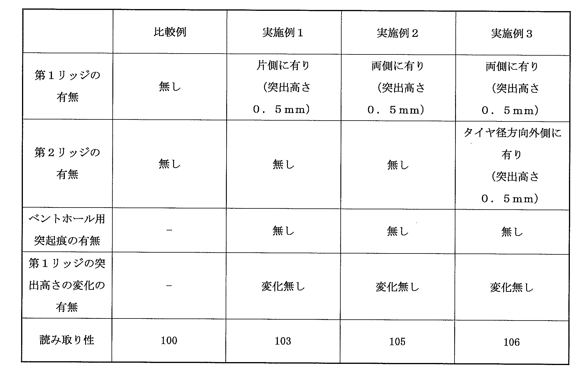
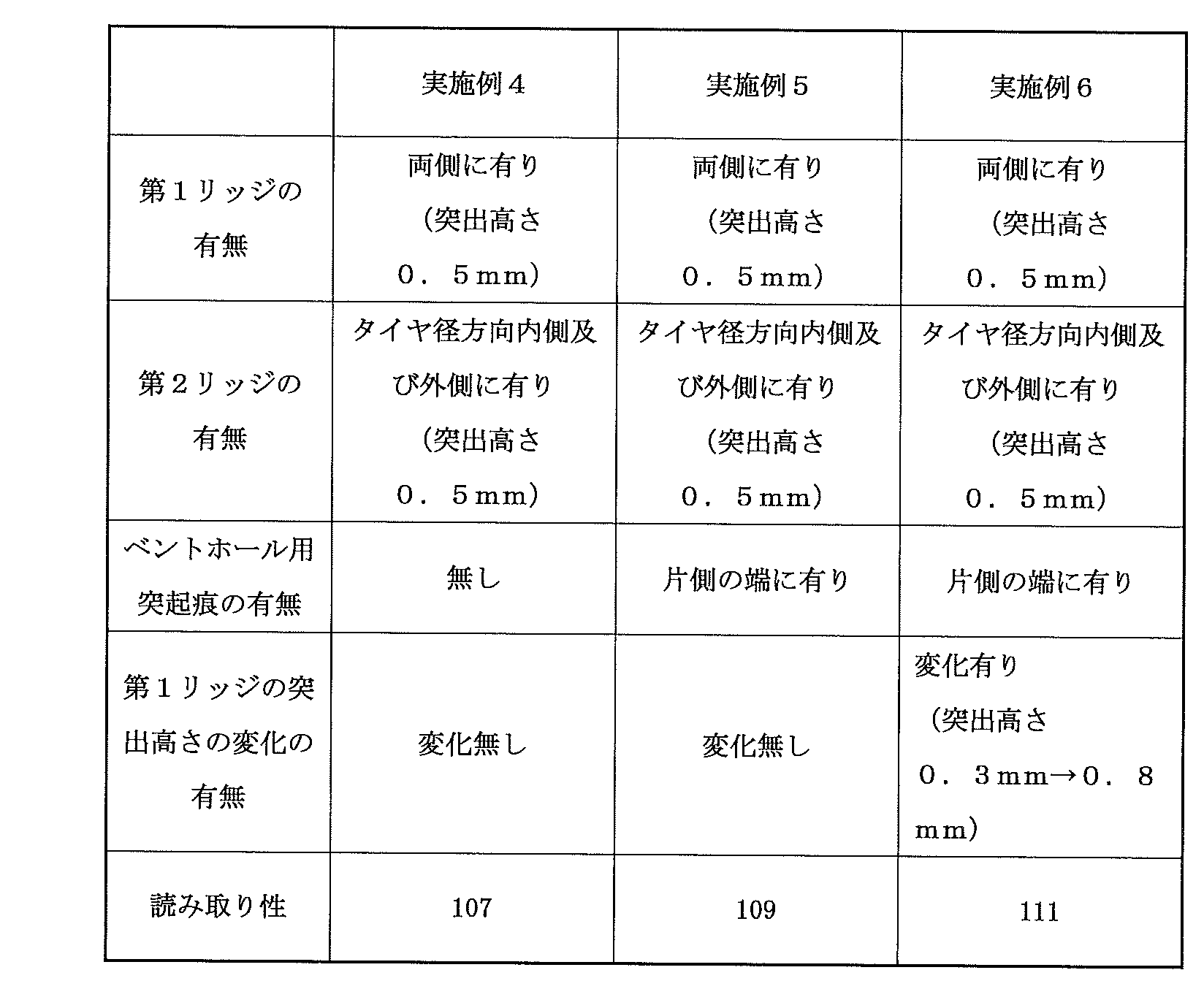
読み取り性は、いずれの例でも、タイヤの使用開始時の読み取り性よりも低下したが、表1より、範囲R1内に、少なくとも1つ第1リッジ60を設けることにより、タイヤの長期使用時の二次元コード40の読み取り性の低下は、第1リッジ60を設けない場合に比べて抑制される、ことがわかる。また、表1,2より、タイヤ周方向に延びる第2リッジ62を範囲R2内に設ける場合、ベントホール用突起痕64が第1リッジ60の端にある場合、第1リッジ60の突出高さを徐々に高くして突出高さの高い側の第1リッジ60の端にベントホール用突起痕64がある場合、タイヤの長期使用時の二次元コード40の読み取り性の低下は抑制される、ことがわかる。
以上、本発明の空気入りタイヤについて詳細に説明したが、本発明は上記実施形態及び実施例に限定されず、本発明の主旨を逸脱しない範囲において、種々の改良や変更してもよいのはもちろんである。
10 空気入りタイヤ
10T トレッド部
10S サイドウォール部
10B ビード部
12 カーカスプライ
12a,12b カーカスプライ材
14 ベルト
14a,14b ベルト材
16 ビードコア
18 トレッドゴム部材
20 サイドゴム部材
22 ビードフィラーゴム部材
24 リムクッションゴム部材
26 インナーライナゴム部材
30 ベルトカバー
40 二次元コード
44 空白領域
56 スムース面
60 第1リッジ
62 第2リッジ
64 ベントホール用突起痕
10T トレッド部
10S サイドウォール部
10B ビード部
12 カーカスプライ
12a,12b カーカスプライ材
14 ベルト
14a,14b ベルト材
16 ビードコア
18 トレッドゴム部材
20 サイドゴム部材
22 ビードフィラーゴム部材
24 リムクッションゴム部材
26 インナーライナゴム部材
30 ベルトカバー
40 二次元コード
44 空白領域
56 スムース面
60 第1リッジ
62 第2リッジ
64 ベントホール用突起痕
Claims (16)
- 空気入りタイヤであって、
円環状の一対のビードコアと、
前記一対のビードコアの周りに巻きまわして前記一対のビードコア間に設けられた、トロイダル状のカーカスプライと、
前記カーカスプライをタイヤ幅方向の外側から覆うように前記空気入りタイヤの側面のそれぞれに設けられた一対のサイドゴム部材と、を備え、
前記側面の少なくとも一方の表面は、スムース面の領域と、該領域内にあり、前記スムース面に対して表面凹凸によって互いに識別可能に形成された2種類の濃淡要素でドットパターンが形成された二次元コードと、を備え、
前記空気入りタイヤの、前記一対のビードコアそれぞれのタイヤ径方向の最も内側の位置からタイヤ最大外径位置までの前記タイヤ径方向に沿った断面高さは80mm以下であり、
前記二次元コードの前記空気入りタイヤのタイヤ周方向に沿った幅の50%の長さだけ、前記二次元コードの前記タイヤ周方向の両側それぞれの縁から前記タイヤ周方向に沿って離れた位置と該縁との間の範囲内の前記空気入りタイヤの表面には、前記スムース面に対して突出して前記タイヤ径方向に延びる1本または複数本の第1リッジが設けられ、前記範囲内の前記第1リッジ以外の部分は、前記スムース面である、ことを特徴とする空気入りタイヤ。 - 前記第1リッジは2本の第1リッジであり、
前記二次元コードの前記タイヤ周方向の両側のそれぞれに前記2本の第1リッジの1つが設けられ、
前記2本の第1リッジは互いに平行である、請求項1に記載の空気入りタイヤ。 - 前記2本の第1リッジそれぞれの、前記2本の第1リッジそれぞれに対して前記二次元コードの最も近い縁までの離間距離は、互いに同じである、請求項2に記載の空気入りタイヤ。
- 前記第1リッジの前記スムース面からの突出高さは、0.3~1.0mmである、請求項1~3のいずれか1項に記載の空気入りタイヤ。
- 前記第1リッジは2本の第1リッジであり、
前記二次元コードの前記タイヤ周方向の両側のそれぞれに前記2本の第1リッジの1つが設けられ、さらに、前記2本の第1リッジの前記タイヤ径方向の両側の端のそれぞれを接続する、前記タイヤ周方向に延びる2本の第2リッジが設けられ、
前記2本の第1リッジと前記2本の第2リッジにより、前記二次元コードは囲まれている、請求項1または4に記載の空気入りタイヤ。 - 前記2本の第1リッジは、互いに平行である、請求項5に記載の空気入りタイヤ。
- 前記2本の第1リッジそれぞれの、前記2本の第1リッジそれぞれに対して前記二次元コードの最も近い縁までの第1離間距離は、互いに同じである、請求項5または6に記載の空気入りタイヤ。
- 前記2本の第2リッジそれぞれの、前記2本の第2リッジそれぞれに対して前記二次元コードの最も近い縁までの第2離間距離は、互いに同じである、請求項5~7のいずれか1項に記載の空気入りタイヤ。
- 前記2本の第2リッジそれぞれの、前記2本の第2リッジそれぞれに対して前記二次元コードの最も近い縁までの第2離間距離は、互いに同じであり、
前記第1離間距離と前記第2離間距離は、同じである、請求項7に記載の空気入りタイヤ。 - 前記2本の第2リッジは、前記二次元コードの、前記タイヤ径方向の外側の縁と前記タイヤ径方向の内側の縁との間の前記側面に沿った長さの50%の長さだけ、前記二次元コードの前記タイヤ径方向の両側それぞれの縁から前記タイヤ径方向に沿って離れ位置と該縁との間の範囲内に設けられる、請求項5~9のいずれか1項に記載の空気入りタイヤ。
- 前記2本の第2リッジの前記スムース面からの突出高さは、0.3~1.0mmである、請求項5~10のいずれか1項に記載の空気入りタイヤ。
- 前記第1リッジの前記タイヤ径方向における端には、ベントホール用突起痕が設けられている、請求項1~11のいずれか1項に記載の空気入りタイヤ。
- 前記第1リッジの、前記スムース面に対する突出高さは、前記第1リッジの一方の端から前記タイヤ径方向に沿って徐々に高くなり、前記ベントホール用突起痕は、前記第1リッジの前記タイヤ径方向の両側の端のうち、前記突出高さの高い方の端に設けられている、請求項12に記載の空気入りタイヤ。
- 前記第1リッジの一方の端と他方の端との間の前記突出高さの差は、0.2~0.5mmである、請求項13に記載の空気入りタイヤ。
- 前記第1リッジは、前記一対のサイドゴム部材の1つと、前記空気入りタイヤのトレッドゴム部材との境界を跨ぐように設けられている、請求項1~14のいずれか1項に記載の空気入りタイヤ。
- 前記範囲内に設けられる前記第1リッジの個数は2つ以下である、請求項1~15のいずれか1項に記載の空気入りタイヤ。
Priority Applications (4)
| Application Number | Priority Date | Filing Date | Title |
|---|---|---|---|
| DE112020003546.8T DE112020003546T5 (de) | 2019-09-30 | 2020-09-01 | Luftreifen |
| JP2021550458A JPWO2021065294A1 (ja) | 2019-09-30 | 2020-09-01 | |
| US17/754,187 US20220297481A1 (en) | 2019-09-30 | 2020-09-01 | Pneumatic tire |
| CN202080067423.9A CN114450177B (zh) | 2019-09-30 | 2020-09-01 | 充气轮胎 |
Applications Claiming Priority (2)
| Application Number | Priority Date | Filing Date | Title |
|---|---|---|---|
| JP2019-178278 | 2019-09-30 | ||
| JP2019178278 | 2019-09-30 |
Publications (1)
| Publication Number | Publication Date |
|---|---|
| WO2021065294A1 true WO2021065294A1 (ja) | 2021-04-08 |
Family
ID=75337881
Family Applications (1)
| Application Number | Title | Priority Date | Filing Date |
|---|---|---|---|
| PCT/JP2020/033102 Ceased WO2021065294A1 (ja) | 2019-09-30 | 2020-09-01 | 空気入りタイヤ |
Country Status (5)
| Country | Link |
|---|---|
| US (1) | US20220297481A1 (ja) |
| JP (1) | JPWO2021065294A1 (ja) |
| CN (1) | CN114450177B (ja) |
| DE (1) | DE112020003546T5 (ja) |
| WO (1) | WO2021065294A1 (ja) |
Citations (3)
| Publication number | Priority date | Publication date | Assignee | Title |
|---|---|---|---|---|
| JP2017514728A (ja) * | 2014-04-30 | 2017-06-08 | コンパニー ゼネラール デ エタブリッスマン ミシュラン | マークを有するタイヤ用モールドのためのモールド要素 |
| WO2018180497A1 (ja) * | 2017-03-28 | 2018-10-04 | 横浜ゴム株式会社 | 空気入りタイヤ、空気入りタイヤの金型、二次元コードの刻印の検査方法、及び空気入りタイヤを製造する方法 |
| US20190135011A1 (en) * | 2017-11-03 | 2019-05-09 | The Goodyear Tire & Rubber Company | Quiet zone for digital code pattern on a rubber article |
Family Cites Families (13)
| Publication number | Priority date | Publication date | Assignee | Title |
|---|---|---|---|---|
| JPH09249006A (ja) * | 1996-01-12 | 1997-09-22 | Yokohama Rubber Co Ltd:The | 偏平空気入りラジアルタイヤ |
| JP4169571B2 (ja) * | 2002-10-21 | 2008-10-22 | 横浜ゴム株式会社 | タイヤ金型及び空気入りタイヤ |
| JP4568274B2 (ja) | 2003-06-23 | 2010-10-27 | ブリヂストン アメリカズ タイヤ オペレイションズ エルエルシー | 空気入りタイヤに刻印する方法及びシステム |
| US8256479B2 (en) * | 2006-05-24 | 2012-09-04 | The Yokohama Rubber Co., Ltd. | Pneumatic tire |
| JP4687811B2 (ja) * | 2009-04-10 | 2011-05-25 | 横浜ゴム株式会社 | 空気入りタイヤ |
| EP2738015B1 (en) * | 2011-07-28 | 2019-06-05 | Bridgestone Corporation | Pneumatic radial tire for passenger vehicle and method for using same |
| FR3020594B1 (fr) * | 2014-04-30 | 2018-01-05 | Compagnie Generale Des Etablissements Michelin | Pneumatique comportant un symbole matriciel a fort contraste sur le flanc |
| DE112015004233T5 (de) * | 2014-09-17 | 2017-06-14 | The Yokohama Rubber Co., Ltd. | Luftreifen |
| JP6947578B2 (ja) * | 2017-08-01 | 2021-10-13 | Toyo Tire株式会社 | 空気入りタイヤ |
| JP7124312B2 (ja) * | 2017-12-20 | 2022-08-24 | 横浜ゴム株式会社 | 空気入りタイヤ |
| JP7140144B2 (ja) * | 2018-01-30 | 2022-09-21 | 横浜ゴム株式会社 | 空気入りタイヤ |
| CN109816078A (zh) * | 2019-03-29 | 2019-05-28 | 安徽佳通乘用子午线轮胎有限公司 | 一种轮胎胎侧可识别的二维码 |
| JP7393628B2 (ja) * | 2019-09-30 | 2023-12-07 | 横浜ゴム株式会社 | 空気入りタイヤ |
-
2020
- 2020-09-01 JP JP2021550458A patent/JPWO2021065294A1/ja active Pending
- 2020-09-01 US US17/754,187 patent/US20220297481A1/en active Pending
- 2020-09-01 CN CN202080067423.9A patent/CN114450177B/zh active Active
- 2020-09-01 DE DE112020003546.8T patent/DE112020003546T5/de active Pending
- 2020-09-01 WO PCT/JP2020/033102 patent/WO2021065294A1/ja not_active Ceased
Patent Citations (3)
| Publication number | Priority date | Publication date | Assignee | Title |
|---|---|---|---|---|
| JP2017514728A (ja) * | 2014-04-30 | 2017-06-08 | コンパニー ゼネラール デ エタブリッスマン ミシュラン | マークを有するタイヤ用モールドのためのモールド要素 |
| WO2018180497A1 (ja) * | 2017-03-28 | 2018-10-04 | 横浜ゴム株式会社 | 空気入りタイヤ、空気入りタイヤの金型、二次元コードの刻印の検査方法、及び空気入りタイヤを製造する方法 |
| US20190135011A1 (en) * | 2017-11-03 | 2019-05-09 | The Goodyear Tire & Rubber Company | Quiet zone for digital code pattern on a rubber article |
Also Published As
| Publication number | Publication date |
|---|---|
| JPWO2021065294A1 (ja) | 2021-04-08 |
| US20220297481A1 (en) | 2022-09-22 |
| CN114450177B (zh) | 2023-11-21 |
| DE112020003546T5 (de) | 2022-04-14 |
| CN114450177A (zh) | 2022-05-06 |
Similar Documents
| Publication | Publication Date | Title |
|---|---|---|
| JP7140144B2 (ja) | 空気入りタイヤ | |
| JP7136126B2 (ja) | 空気入りタイヤ | |
| JP7393628B2 (ja) | 空気入りタイヤ | |
| JP7124312B2 (ja) | 空気入りタイヤ | |
| CN114450177B (zh) | 充气轮胎 | |
| WO2019069487A1 (ja) | 空気入りタイヤ | |
| JP7200486B2 (ja) | 空気入りタイヤ | |
| JP7417111B2 (ja) | 空気入りタイヤ | |
| JP7279409B2 (ja) | 空気入りタイヤ | |
| JP7043855B2 (ja) | 空気入りタイヤ | |
| JP7448784B2 (ja) | 空気入りタイヤ | |
| JP7211370B2 (ja) | 空気入りタイヤ | |
| JP7035659B2 (ja) | 空気入りタイヤ | |
| JP7151326B2 (ja) | 空気入りタイヤ | |
| JP7159573B2 (ja) | 空気入りタイヤ | |
| JPWO2019069487A1 (ja) | 空気入りタイヤ | |
| JP4577005B2 (ja) | 小型トラック用空気入りタイヤ |
Legal Events
| Date | Code | Title | Description |
|---|---|---|---|
| 121 | Ep: the epo has been informed by wipo that ep was designated in this application |
Ref document number: 20871492 Country of ref document: EP Kind code of ref document: A1 |
|
| ENP | Entry into the national phase |
Ref document number: 2021550458 Country of ref document: JP Kind code of ref document: A |
|
| 122 | Ep: pct application non-entry in european phase |
Ref document number: 20871492 Country of ref document: EP Kind code of ref document: A1 |