WO2021065129A1 - Dispositif d'étanchéité - Google Patents
Dispositif d'étanchéité Download PDFInfo
- Publication number
- WO2021065129A1 WO2021065129A1 PCT/JP2020/026027 JP2020026027W WO2021065129A1 WO 2021065129 A1 WO2021065129 A1 WO 2021065129A1 JP 2020026027 W JP2020026027 W JP 2020026027W WO 2021065129 A1 WO2021065129 A1 WO 2021065129A1
- Authority
- WO
- WIPO (PCT)
- Prior art keywords
- lip portion
- sealing
- main body
- target side
- sealing target
- Prior art date
Links
- 238000007789 sealing Methods 0.000 title claims description 159
- 230000013011 mating Effects 0.000 claims description 73
- XLYOFNOQVPJJNP-UHFFFAOYSA-N water Substances O XLYOFNOQVPJJNP-UHFFFAOYSA-N 0.000 description 10
- 239000012530 fluid Substances 0.000 description 7
- 230000003014 reinforcing effect Effects 0.000 description 7
- 230000002093 peripheral effect Effects 0.000 description 5
- 230000000052 comparative effect Effects 0.000 description 4
- 238000000465 moulding Methods 0.000 description 4
- 239000007787 solid Substances 0.000 description 4
- 229920000459 Nitrile rubber Polymers 0.000 description 3
- 238000004132 cross linking Methods 0.000 description 2
- 229920001971 elastomer Polymers 0.000 description 2
- 239000000463 material Substances 0.000 description 2
- 239000005060 rubber Substances 0.000 description 2
- 229920000800 acrylic rubber Polymers 0.000 description 1
- 230000001174 ascending effect Effects 0.000 description 1
- 238000005452 bending Methods 0.000 description 1
- 239000010960 cold rolled steel Substances 0.000 description 1
- 230000000694 effects Effects 0.000 description 1
- 229920001973 fluoroelastomer Polymers 0.000 description 1
- -1 for example Substances 0.000 description 1
- 238000005242 forging Methods 0.000 description 1
- 229920000058 polyacrylate Polymers 0.000 description 1
- 239000010935 stainless steel Substances 0.000 description 1
- 229910001220 stainless steel Inorganic materials 0.000 description 1
- 229920003051 synthetic elastomer Polymers 0.000 description 1
- 239000005061 synthetic rubber Substances 0.000 description 1
- 238000004073 vulcanization Methods 0.000 description 1
Images


Classifications
-
- F—MECHANICAL ENGINEERING; LIGHTING; HEATING; WEAPONS; BLASTING
- F16—ENGINEERING ELEMENTS AND UNITS; GENERAL MEASURES FOR PRODUCING AND MAINTAINING EFFECTIVE FUNCTIONING OF MACHINES OR INSTALLATIONS; THERMAL INSULATION IN GENERAL
- F16J—PISTONS; CYLINDERS; SEALINGS
- F16J15/00—Sealings
- F16J15/16—Sealings between relatively-moving surfaces
- F16J15/34—Sealings between relatively-moving surfaces with slip-ring pressed against a more or less radial face on one member
- F16J15/3436—Pressing means
- F16J15/3456—Pressing means without external means for pressing the ring against the face, e.g. slip-ring with a resilient lip
-
- F—MECHANICAL ENGINEERING; LIGHTING; HEATING; WEAPONS; BLASTING
- F02—COMBUSTION ENGINES; HOT-GAS OR COMBUSTION-PRODUCT ENGINE PLANTS
- F02F—CYLINDERS, PISTONS OR CASINGS, FOR COMBUSTION ENGINES; ARRANGEMENTS OF SEALINGS IN COMBUSTION ENGINES
- F02F11/00—Arrangements of sealings in combustion engines
-
- F—MECHANICAL ENGINEERING; LIGHTING; HEATING; WEAPONS; BLASTING
- F02—COMBUSTION ENGINES; HOT-GAS OR COMBUSTION-PRODUCT ENGINE PLANTS
- F02P—IGNITION, OTHER THAN COMPRESSION IGNITION, FOR INTERNAL-COMBUSTION ENGINES; TESTING OF IGNITION TIMING IN COMPRESSION-IGNITION ENGINES
- F02P13/00—Sparking plugs structurally combined with other parts of internal-combustion engines
-
- F—MECHANICAL ENGINEERING; LIGHTING; HEATING; WEAPONS; BLASTING
- F02—COMBUSTION ENGINES; HOT-GAS OR COMBUSTION-PRODUCT ENGINE PLANTS
- F02P—IGNITION, OTHER THAN COMPRESSION IGNITION, FOR INTERNAL-COMBUSTION ENGINES; TESTING OF IGNITION TIMING IN COMPRESSION-IGNITION ENGINES
- F02P15/00—Electric spark ignition having characteristics not provided for in, or of interest apart from, groups F02P1/00 - F02P13/00 and combined with layout of ignition circuits
-
- F—MECHANICAL ENGINEERING; LIGHTING; HEATING; WEAPONS; BLASTING
- F16—ENGINEERING ELEMENTS AND UNITS; GENERAL MEASURES FOR PRODUCING AND MAINTAINING EFFECTIVE FUNCTIONING OF MACHINES OR INSTALLATIONS; THERMAL INSULATION IN GENERAL
- F16J—PISTONS; CYLINDERS; SEALINGS
- F16J15/00—Sealings
- F16J15/16—Sealings between relatively-moving surfaces
- F16J15/32—Sealings between relatively-moving surfaces with elastic sealings, e.g. O-rings
- F16J15/3204—Sealings between relatively-moving surfaces with elastic sealings, e.g. O-rings with at least one lip
-
- F—MECHANICAL ENGINEERING; LIGHTING; HEATING; WEAPONS; BLASTING
- F16—ENGINEERING ELEMENTS AND UNITS; GENERAL MEASURES FOR PRODUCING AND MAINTAINING EFFECTIVE FUNCTIONING OF MACHINES OR INSTALLATIONS; THERMAL INSULATION IN GENERAL
- F16J—PISTONS; CYLINDERS; SEALINGS
- F16J15/00—Sealings
- F16J15/16—Sealings between relatively-moving surfaces
- F16J15/32—Sealings between relatively-moving surfaces with elastic sealings, e.g. O-rings
- F16J15/3268—Mounting of sealing rings
- F16J15/3276—Mounting of sealing rings with additional static sealing between the sealing, or its casing or support, and the surface on which it is mounted
-
- F—MECHANICAL ENGINEERING; LIGHTING; HEATING; WEAPONS; BLASTING
- F16—ENGINEERING ELEMENTS AND UNITS; GENERAL MEASURES FOR PRODUCING AND MAINTAINING EFFECTIVE FUNCTIONING OF MACHINES OR INSTALLATIONS; THERMAL INSULATION IN GENERAL
- F16J—PISTONS; CYLINDERS; SEALINGS
- F16J15/00—Sealings
- F16J15/56—Other sealings for reciprocating rods
Definitions
- the present invention relates to a sealing device.
- Patent Document 1 discloses a sealing device that seals an annular gap between a plug tube of an ignition device provided in an engine head of an engine and an annular gap between the head cover of the engine.
- the sealing device is composed of a plug tube sealing member that seals oil and a waterproof sealing member having a U-shaped cross section, and it is required to integrate these members to reduce the number of parts.
- the sealing device When integrating the sealing device, it is conceivable to newly provide a lip portion.
- the position of the mating member for example, the upper part of the coil body of the ignition device
- a desired surface pressure can be obtained when the crushing allowance of the new lip portion is small, but the contact area is obtained when the crushing allowance is large. May become large (become solid) and the desired surface pressure may not be obtained. Therefore, according to the present invention, the number of parts can be reduced, and the sealing property can be improved by obtaining a desired surface pressure not only when the crushing allowance of the side lip portion is small but also when the crushing allowance is large. It is an object of the present invention to provide a sealing device that can be secured.
- the present invention is a sealing device including an elastic body portion that seals an annular gap between an inner member and an outer member, wherein the elastic body portion includes an annular main body portion arranged in the gap and the main body.
- the seal lip portion extending from the sealing target side of the portion and contacting the inner member and the surface extending outward from the end of the main body portion on the anti-sealing target side, and the surface on the sealing target side contacts the outer member.
- Flange portion, side lip portion extending in a direction away from the end of the main body portion on the anti-sealing target side, and the surface of the flange portion on the anti-sealing target side in the circumferential direction. It is characterized in that the back surface of the side lip portion comes into contact with the protrusion by pressing the side lip portion with the formed protrusion and the mating member arranged on the anti-sealing target side.
- the present invention is a sealing device including an elastic body portion that seals an annular gap between the inner member and the outer member, wherein the elastic body portion includes an annular main body portion arranged in the gap and an annular main body portion.
- the seal lip portion extending from the sealing target side of the main body portion and coming into contact with the inner member and the sealing lip portion extending outward from the end of the main body portion on the anti-sealing target side, and the surface on the sealing target side is the outer member.
- a flange portion that comes into contact with the surface a side lip portion that extends from the end of the main body portion on the anti-sealing target side in a direction away from the sealing target side, and a side lip portion that is formed on the back surface of the side lip portion in the circumferential direction. It is characterized in that the side lip portion is pressed by a mating member arranged on the anti-sealing target side, so that the protrusion portion comes into contact with the flange portion.
- the present invention is a sealing device including an elastic body portion that seals an annular gap between the inner member and the outer member, wherein the elastic body portion includes an annular main body portion arranged in the gap and an annular main body portion.
- the seal lip portion extending from the sealing target side of the main body portion and coming into contact with the inner member and the sealing lip portion extending outward from the end of the main body portion on the anti-sealing target side, and the surface on the sealing target side is the outer member.
- a flange portion that comes into contact with the main body portion, a side lip portion that extends in a direction away from the sealing target side from the end of the main body portion on the anti-sealing target side, and an extension of the side lip portion on the surface of the side lip portion.
- the side lip portion is pressed by a mating member arranged on the anti-sealing target side, which has protrusions formed in a plurality of directions in the circumferential direction, so that the back surface of the side lip portion is pressed.
- the flange portion comes into contact with the surface of the flange portion on the anti-sealing target side, and the protrusion portion comes into contact with the mating member.
- the present invention is a sealing device including an elastic body portion that seals an annular gap between an inner member and an outer member, wherein the elastic body portion includes an annular main body portion arranged in the gap and an annular main body portion.
- the seal lip portion extending from the sealing target side of the main body portion and coming into contact with the inner member and the sealing lip portion extending outward from the end of the main body portion on the anti-sealing target side, and the surface on the sealing target side is the outer member.
- a flange portion that comes into contact with the main body portion a side lip portion that extends in a direction away from the sealing target side from the end of the main body portion on the anti-sealing target side, and a circumferential direction with the back surface side of the side lip portion as a convex side. It is characterized in that the bent portion has a bent portion that is bent over the entire surface, and the side lip portion is pressed by a mating member arranged on the anti-sealing target side so that the bent portion comes into contact with the flange portion.
- the seal lip portion and the side lip portion on the elastic body portion, it is possible to achieve both the sealing function of the fluid to be sealed such as oil and the waterproof function, and to reduce the number of parts. Can be done. Further, when the sealing device is assembled, if the gap between the mating member and the sealing portion is small due to the variation in the position of the mating member, the side lip portion comes into contact with the protrusion provided on the flange portion, so that a desired surface pressure can be obtained. It is possible to secure the sealing property. Further, when the gap between the mating member and the sealing portion is large, the side lip portion comes into contact with the mating member, so that a desired surface pressure can be obtained and the sealing property can be ensured.
- the side lip portion has a protrusion
- the gap between the mating member and the seal portion is small due to the variation in the position of the mating member, the protruding portion of the side lip portion comes into contact with the flange portion, so that the desired surface is formed. It is possible to obtain pressure and secure the sealing property. Further, when the gap between the mating member and the sealing portion is large, the side lip portion comes into contact with the mating member, so that a desired surface pressure can be obtained and the sealing property can be ensured.
- the gap between the mating member and the seal portion is small due to the variation in the position of the mating member, the plurality of protrusions of the side lip portion come into contact with the mating member. Therefore, a desired surface pressure can be obtained and the sealing property can be ensured. Further, when the gap between the mating member and the sealing portion is large, the side lip portion comes into contact with the mating member, so that a desired surface pressure can be obtained and the sealing property can be ensured.
- the sealing device According to the sealing device according to the present invention, the number of parts can be reduced, and a desired surface pressure can be obtained not only when the crushing allowance of the side lip portion is small but also when the crushing allowance is large. , Sealing property can be secured.
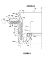
- the sealing device 1 includes an elastic body portion 2 that seals an annular gap between the inner member 101 and the outer member 102.
- the elastic body portion 2 includes a main body portion 11, a seal lip portion 12, a flange portion 13, a side lip portion 14, and a protrusion portion 15.
- the sealing device 1 As shown in FIG. 1, the sealing device 1 according to the first embodiment includes a columnar inner member 101 (for example, a plug tube) that covers the periphery of a spark plug attached to an engine head of an engine (not shown), and an inner member 101. It is a member that seals an annular gap with an outer member 102 (for example, an engine head cover) arranged on the outer side in the radial direction of the engine.
- an outer member 102 for example, an engine head cover
- the sealing device 1 is mainly composed of an elastic body portion 2, a reinforcing ring 3, and a spring member 4.
- the elastic body portion 2 includes a main body portion 11, a seal lip portion 12, a flange portion 13, a side lip portion 14, and a protrusion portion 15.
- the elastic body portion 2 is integrally formed of, for example, various rubber materials.
- the rubber material for example, synthetic rubber such as nitrile rubber (NBR), hydrogenated nitrile rubber (H-NBR), acrylic rubber (ACM), and fluororubber (FKM) can be used.
- the elastic body portion 2 is molded by cross-linking (vulcanization) molding using a molding die. At the time of this cross-linking molding, the reinforcing ring 3 and the spring member 4 arranged in the molding die are cross-linked and bonded to the elastic body portion 2, and each member is integrally formed.
- the main body 11 has an annular shape.
- the main body 11 is arranged in a gap between the outer peripheral surface 101a of the inner member 101 and the inner peripheral surface 102a of the outer member 102.
- the outer peripheral surface 11a of the main body 11 is in contact with the inner peripheral surface 102a of the outer member 102.
- the seal lip portion 12 is a plate-shaped portion extending diagonally upward (anti-sealing target side O) from the end of the main body portion 11 on the sealing target side M toward the inner member 101 side.
- the lip portion 12a of the seal lip portion 12 is in contact with the outer peripheral surface 101a of the inner member 101 in the circumferential direction. As a result, the fluid to be sealed is sealed.
- the flange portion 13 is a plate-shaped portion that projects outward in the radial direction from the end portion of the main body portion 11 on the anti-sealing target side O.
- the flange portion 13 is formed along the main body portion 11 over the entire circumferential direction.
- the back surface (the surface on the sealing target side) 13c of the flange portion 13 is in contact with the end surface 102b of the outer member 102.
- the side lip portion 14 is a plate-shaped portion extending from the end portion of the main body portion 11 on the anti-sealing target side O toward the anti-sealing target side O side (the side separated from the sealing target side M).
- the side lip portion 14 is provided over the entire circumferential direction of the main body portion 11, and the plate thickness becomes thinner toward the tip end. Before assembling, the side lip portion 14 is inclined so as to expand in diameter toward the anti-sealing target side O, as shown in FIG. On the other hand, the side lip portion 14 is pressed by the mating member 103 shown in FIG. 2 to form a seal region between the side lip portion 14 and the protrusion portion 15 to prevent water, muddy water, and the like from entering.
- the mating member is, for example, the upper part of the coil body of the ignition device.
- the protrusion 15 is a protrusion formed over the entire circumferential direction on the surface (the surface on the anti-sealing target side) 13a of the flange portion 13.
- the cross-sectional shape of the protrusion 15 is not particularly limited, but in this embodiment, it is tapered toward the tip. That is, the tip of the protrusion 15 is inclined downward from the surface 13a of the flange 13, and even on the opposite side of the protrusion 15 from the surface 13a of the flange 13, the tip of the protrusion 15 to the groove 13d It slopes down toward the bottom. As a result, the protrusion 15 becomes thicker as it is closer to the base end.
- the bottom portion of the groove portion 13d is deeper than the surface 13a of the flange portion 13.
- the protrusion 15 is formed on the surface 13a of the flange 13 at a position where it can come into contact with the side lip 14.
- the reinforcing ring 3 is a reinforcing member that reinforces the main body portion 11 and the flange portion 13.
- the reinforcing ring 3 is made of, for example, stainless steel, SPCC (cold rolled steel), or the like.
- the reinforcing ring 3 has a side portion 3a arranged inside the main body portion 11 and an overhanging portion 3b arranged inside the flange portion 13, and has an L-shaped cross section.
- the reinforcing ring 3 is manufactured by, for example, pressing or forging.
- the spring member 4 is arranged at the tip of the seal lip 12 in the circumferential direction.
- a garter spring can be used as the spring member 4.
- the spring member 4 applies a tense force in the direction of reducing the diameter at the lip portion 12a of the seal lip 12.
- FIG. 2 is a semi-cross-sectional view at the time of assembly showing the sealing device according to the first embodiment cut by a plane passing through the axis.
- the seal lip portion 12 comes into contact with the inner member 101 in the circumferential direction due to the urging force tilting toward the inner member 101 and the tense force of the spring member 4.
- the sealing device 1 is incorporated, and the surface 14a of the side lip portion 14 is pressed by the mating member 103, so that the tip end side of the side lip portion 14 is tilted in the out-diameter direction, and the back surface 14b of the side lip portion 14 is projected.
- Contact part 15 A seal region is formed between the back surface 14b of the side lip portion 14 and the protrusion 15 to prevent water, muddy water, and the like from entering.
- the elastic body portion 2 by providing the elastic body portion 2 with the seal lip portion 12 and the side lip portion 14, it is possible to achieve both the sealing function of the fluid to be sealed such as oil and the waterproof function, and the number of parts. Can be reduced. Further, when the sealing device 1 is assembled, even if the gap between the mating member 103 and the outer member 102 is small due to the variation in the position of the mating member 103, the side lip portion 14 has a flange portion 13 due to the side lip portion 14 having a large crushing allowance. Since the crushing allowance of the protrusion 15 provided on the surface is also large, the sealing property can be ensured by obtaining a desired surface pressure.
- the protrusion 15 has no crushing allowance or is in a small state, but the side When the lip portion 14 and the mating member 103 come into contact with each other, a desired surface pressure can be obtained and the sealing property can be ensured.
- the flange portion is not provided with a protrusion and the flange portion and the side lip portion are brought into contact with each other, the flange portion and the side lip portion become solid and it becomes difficult to increase the surface pressure.
- the tapered protrusion 15 since the tapered protrusion 15 is provided, the surface pressure between the side lip portion 14 and the protrusion 15 can be increased. Further, due to the variation in the position of the mating member 103 (variation in the axis Z direction), a desired surface pressure can be obtained regardless of whether the gap between the mating member 103 and the outer member 102 is small or large. Therefore, the sealing property between the side lip portion 14 and the protrusion portion 15 can be ensured.
- the sealing device 1A according to the second embodiment will be described.
- the second embodiment is different from the first embodiment in that the protrusion 15A is provided on the side lip portion 14.
- the parts different from the first embodiment will be mainly described.
- a protrusion 15A is provided on the tip end side of the back surface 14b of the side lip portion 14 (the surface of the side lip portion 14 on the flange portion 13 side).
- the protrusion 15A is inclined upward from the tip to the tip of the side lip 14, and the protrusion 15A is from the tip to the back surface 14b of the side lip 14 even on the side close to the base end side of the side lip 14 on the opposite side. Ascending and sloping. As a result, the protrusion 15A becomes thicker as it is closer to the base end.
- the protrusion 15A is formed over the entire circumferential direction.
- the cross-sectional shape of the protrusion 15A is tapered toward the tip.
- the surface (the surface on the anti-sealing target side) 13b of the flange portion 13 is flat.
- a seal region is formed between the protrusion 15A of the side lip portion 14 and the surface 13b of the flange portion 13 to prevent water, muddy water, and the like from entering.
- the protrusion 15A has no crushing allowance or is in a small state, but the side When the lip portion 14 and the mating member 103 come into contact with each other, a desired surface pressure can be obtained and the sealing property can be ensured.
- the elastic body portion 2 by providing the elastic body portion 2 with the seal lip portion 12 and the side lip portion 14, it is possible to achieve both the sealing function of the fluid to be sealed such as oil and the waterproof function, and the number of parts. Can be reduced. Further, when the sealing device 1A is assembled, a desired surface pressure can be obtained regardless of whether the gap between the mating member 103 and the outer member 102 is small or large due to the variation in the position of the mating member 103 (variation in the axis Z direction). , Sealing property can be ensured.
- the third embodiment is different from the first embodiment in that the protrusions 15B are provided at a plurality of positions on the surface 14a of the side lip portion 14 in the extending direction of the side lip portion 14.
- the parts different from the first embodiment will be mainly described.
- the protrusions 15B are formed at a plurality of locations in the extending direction of the side lip portion 14 on the surface 14a (the surface on the semi-sealed target side) of the side lip portion 14 over the circumferential direction.
- a plurality of protrusions 15B are provided at predetermined intervals in the extending direction of the side lip portion 14.
- two protrusions 15B are provided, one on the outside of the side lip portion 14 in the extending direction and the other on the inside of the side lip portion 14 in the extending direction.
- Each of the protrusions 15B has a tapered shape.
- two protrusions 15B are provided, but three or more protrusions 15B may be provided.
- the surface 14a of the side lip portion 14 is the mating. It is pressed by the member 103. Therefore, the tip end side of the side lip portion 14 is tilted in the out-of-diameter direction, the back surface 14b of the side lip portion 14 abuts on the surface 13a of the flange portion 13, and the protrusions 15B and 15B abut on the mating member 103.
- a seal region is formed between the back surface 14b of the side lip portion 14 and the surface 13a of the flange portion 13 to prevent water, muddy water, and the like from entering.
- the surface pressure can be increased without the flange portion 13 and the side lip portion 14 becoming solid.
- the gap between the mating member 103 and the outer member 102 is large due to the variation in the position of the mating member 103, the side lip portion 14 and the mating member 103 come into contact with each other to obtain a desired surface pressure, and the sealing property is obtained. Can be secured.
- the surface pressure can be increased at the position corresponding to the protrusion 15B, and the sealing property is ensured. be able to.
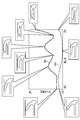
- FIG. 8 shows a case where the horizontal axis is the crushing allowance of the side lip portion 14 and the vertical axis is the maximum value (peak surface pressure) of the surface pressure between the side lip portion 14 and the mating member 103 in the sealing device 1B.
- the graph is shown.
- Graph line 50 shows the value of the sealing device 1B.
- the graph line 150 shows the value of the comparative example which is the configuration in which the protrusion 15 is removed from the sealing device 1 of the first embodiment.
- the balloons attached to the graph lines 50 and 150 indicate the crushed state of the side lip portion 14 when the value is taken.
- the value of the graph line 50 of the sealing device 1B consistently shows a large peak surface pressure as compared with the graph line 150 of the comparative example, regardless of the size of the crushing allowance on the horizontal axis.
- the elastic body portion 2 with the seal lip portion 12 and the side lip portion 14, it is possible to achieve both the sealing function of the fluid to be sealed such as oil and the waterproof function, and the number of parts. Can be reduced.
- a desired surface pressure can be obtained regardless of whether the gap between the mating member 103 and the outer member 102 is small or large due to the variation in the position of the mating member 103 (variation in the axis Z direction). , Sealing property can be ensured.
- the sealing device 1C according to the fourth embodiment will be described.
- the side lip portion 14 is formed with a bent portion 15C bent in the circumferential direction with the back surface 14b side (sealing target side) as the convex side. Therefore, the tip side of the side lip portion 14 with respect to the bent portion 15C is in a state of standing up toward the anti-sealing target side O.
- the surface 14a of the side lip portion 14 is the mating member. Pressed by 103. Therefore, the tip end side of the side lip portion 14 is tilted in the out-of-diameter direction, the convex shape of the bent portion 15C abuts on the front surface 13a of the flange portion 13 on the back surface 14b side of the side lip portion 14, and the back surface 14b of the side lip portion 14 The side abuts on the mating member 103.
- a seal region is formed between the back surface 14b of the side lip portion 14 and the surface 13a of the flange portion 13 to prevent water, muddy water, and the like from entering.
- the surface pressure can be increased without the flange portion 13 and the side lip portion 14 becoming solid.
- the gap between the mating member 103 and the outer member 102 is large due to the variation in the position of the mating member 103, the tip of the side lip portion 14 and the mating member 103 come into contact with each other, so that a desired surface pressure can be obtained. Sealability can be ensured.
- the horizontal axis is the crushing allowance of the side lip portion 14, and the vertical axis is the maximum value (peak surface pressure) of the surface pressure between the side lip portion 14 and the mating member 103.
- the graph is shown.
- the graph line 51 shows the value of the sealing device 1C.
- the graph line 151 shows the value of the comparative example which is the configuration in which the protrusion 15 is removed from the sealing device 1 of the first embodiment.
- the balloons attached to the graph lines 51 and 151 indicate the crushed state of the side lip portion 14 when the value is taken.
- the value of the graph line 51 of the sealing device 1B can consistently maintain a substantially constant peak surface pressure regardless of the size of the crushing allowance on the horizontal axis, as compared with the graph line 151 of the comparative example. .. Therefore, according to the sealing device 1B, the peak surface pressure does not become excessively weak regardless of the size of the crushing allowance.
- the elastic body portion 2 by providing the elastic body portion 2 with the seal lip portion 12 and the side lip portion 14, it is possible to achieve both the sealing function of the fluid to be sealed such as oil and the waterproof function, and the number of parts. Can be reduced.
- sealing device 1C when the sealing device 1C is assembled, a desired surface pressure can be obtained regardless of whether the gap between the mating member 103 and the outer member 102 is small or large due to the variation in the position of the mating member 103 (variation in the axis Z direction). , Sealing property can be ensured.
Landscapes
- Engineering & Computer Science (AREA)
- General Engineering & Computer Science (AREA)
- Mechanical Engineering (AREA)
- Chemical & Material Sciences (AREA)
- Combustion & Propulsion (AREA)
- Gasket Seals (AREA)
- Sealing With Elastic Sealing Lips (AREA)
Abstract
La présente invention concerne une partie (2) d'un corps élastique qui comprend une partie corps principal annulaire (11) disposée dans un espace, une partie lèvre d'étanchéité (12) qui s'étend à partir du côté de la partie corps principal (11) étanche, et qui vient en contact avec un élément intérieur (101), une partie bride (13) qui s'étend vers l'extérieur à partir d'une partie de bord de la partie de corps principal (11) sur le côté opposé au côté scellé, et dont une surface sur le côté scellé entre en contact avec un élément extérieur (102), une partie lèvre latérale (14) s'étendant à partir de la partie de bord de la partie corps principal (11) sur le côté opposé au côté scellé, dans une direction s'éloignant du côté scellé, et une partie en saillie (15) formée s'étendant dans la direction circonférentielle sur la surface de la partie bride (13) sur le côté opposé au côté scellé, caractérisé en ce qu'une surface arrière (14b) de la partie lèvre latérale (14) est amenée en contact avec la partie en saillie (15) par la partie lèvre latérale (14) qui est pressée par un élément de contrepartie (103) disposé sur le côté opposé au côté scellé.
Priority Applications (3)
| Application Number | Priority Date | Filing Date | Title |
|---|---|---|---|
| CN202080060075.2A CN114341478A (zh) | 2019-09-30 | 2020-07-02 | 密封装置 |
| JP2021550341A JP7441849B2 (ja) | 2019-09-30 | 2020-07-02 | 密封装置 |
| US17/764,605 US20220341493A1 (en) | 2019-09-30 | 2020-07-02 | Sealing device |
Applications Claiming Priority (4)
| Application Number | Priority Date | Filing Date | Title |
|---|---|---|---|
| JP2019178229 | 2019-09-30 | ||
| JP2019-178229 | 2019-09-30 | ||
| JP2020-074781 | 2020-04-20 | ||
| JP2020074781 | 2020-04-20 |
Publications (1)
| Publication Number | Publication Date |
|---|---|
| WO2021065129A1 true WO2021065129A1 (fr) | 2021-04-08 |
Family
ID=75336393
Family Applications (1)
| Application Number | Title | Priority Date | Filing Date |
|---|---|---|---|
| PCT/JP2020/026027 WO2021065129A1 (fr) | 2019-09-30 | 2020-07-02 | Dispositif d'étanchéité |
Country Status (4)
| Country | Link |
|---|---|
| US (1) | US20220341493A1 (fr) |
| JP (1) | JP7441849B2 (fr) |
| CN (1) | CN114341478A (fr) |
| WO (1) | WO2021065129A1 (fr) |
Citations (4)
| Publication number | Priority date | Publication date | Assignee | Title |
|---|---|---|---|---|
| JPS5167961U (fr) * | 1974-11-22 | 1976-05-29 | ||
| JP2014101897A (ja) * | 2012-11-16 | 2014-06-05 | Koyo Sealing Techno Co Ltd | 密封装置 |
| JP2017089801A (ja) * | 2015-11-12 | 2017-05-25 | 光洋シーリングテクノ株式会社 | デフサイド用の密封装置 |
| JP2017198253A (ja) * | 2016-04-26 | 2017-11-02 | Nok株式会社 | 密封装置 |
Family Cites Families (19)
| Publication number | Priority date | Publication date | Assignee | Title |
|---|---|---|---|---|
| US2873153A (en) * | 1956-06-29 | 1959-02-10 | Federal Mogul Bower Bearings | Bearing shaft seal |
| JP2002098231A (ja) * | 2000-09-21 | 2002-04-05 | Toyoda Gosei Co Ltd | 弾性ガスケット |
| JP4014423B2 (ja) * | 2001-03-09 | 2007-11-28 | 株式会社マーレ フィルターシステムズ | シリンダヘッドカバーにおける点火栓チューブ挿入部のシール装置 |
| DE102005004323A1 (de) * | 2005-01-31 | 2006-09-28 | Robert Bosch Gmbh | Dichtelement und Antriebseinheit beinhaltend ein Dichtelement |
| JP2009103177A (ja) | 2007-10-22 | 2009-05-14 | Nok Corp | オイルシール |
| CN102016365A (zh) * | 2008-04-25 | 2011-04-13 | Nok株式会社 | 密封装置 |
| JP5469497B2 (ja) * | 2010-03-26 | 2014-04-16 | Ntn株式会社 | 車輪用軸受装置 |
| CN102947629A (zh) * | 2010-06-15 | 2013-02-27 | 内山工业株式会社 | 环状弹性密封圈 |
| JP5677565B2 (ja) * | 2011-04-06 | 2015-02-25 | 本田技研工業株式会社 | シール部材及びエンジンのプラグチューブシール構造 |
| JP5778238B2 (ja) * | 2013-11-18 | 2015-09-16 | Nok株式会社 | 密封装置の製造方法 |
| JP6490348B2 (ja) * | 2014-03-31 | 2019-03-27 | Ntn株式会社 | プーリユニット |
| EP3147544A4 (fr) * | 2014-05-20 | 2018-02-28 | NOK Corporation | Dispositif d'étanchéité |
| JP6864624B2 (ja) * | 2015-09-25 | 2021-04-28 | Nok株式会社 | ディファレンシャル機構用密封装置 |
| JP2017150531A (ja) * | 2016-02-23 | 2017-08-31 | Ntn株式会社 | 油圧式オートテンショナ |
| DE102016124571B4 (de) * | 2016-12-16 | 2019-10-10 | Schaeffler Technologies AG & Co. KG | Dichtungsvorrichtung und Dichtungsanordnung |
| CA3064941A1 (fr) * | 2017-06-13 | 2018-12-20 | Stemco Products, Inc. | Joint d'ensemble d'extremite de roue |
| JP6890489B2 (ja) * | 2017-07-07 | 2021-06-18 | Nok株式会社 | 密封装置 |
| JP7391646B2 (ja) * | 2019-12-10 | 2023-12-05 | Nok株式会社 | 密封装置 |
| US20210341058A1 (en) * | 2020-05-04 | 2021-11-04 | Saint-Gobain Performance Plastics Corporation | Metallic seal for valve assembly |
-
2020
- 2020-07-02 CN CN202080060075.2A patent/CN114341478A/zh active Pending
- 2020-07-02 JP JP2021550341A patent/JP7441849B2/ja active Active
- 2020-07-02 WO PCT/JP2020/026027 patent/WO2021065129A1/fr active Application Filing
- 2020-07-02 US US17/764,605 patent/US20220341493A1/en active Pending
Patent Citations (4)
| Publication number | Priority date | Publication date | Assignee | Title |
|---|---|---|---|---|
| JPS5167961U (fr) * | 1974-11-22 | 1976-05-29 | ||
| JP2014101897A (ja) * | 2012-11-16 | 2014-06-05 | Koyo Sealing Techno Co Ltd | 密封装置 |
| JP2017089801A (ja) * | 2015-11-12 | 2017-05-25 | 光洋シーリングテクノ株式会社 | デフサイド用の密封装置 |
| JP2017198253A (ja) * | 2016-04-26 | 2017-11-02 | Nok株式会社 | 密封装置 |
Also Published As
| Publication number | Publication date |
|---|---|
| CN114341478A (zh) | 2022-04-12 |
| US20220341493A1 (en) | 2022-10-27 |
| JPWO2021065129A1 (fr) | 2021-04-08 |
| JP7441849B2 (ja) | 2024-03-01 |
Similar Documents
| Publication | Publication Date | Title |
|---|---|---|
| JP6502318B2 (ja) | ガスケット | |
| US20150354703A1 (en) | Lip seal with inversion prevention feature | |
| US7648144B2 (en) | Sealing device | |
| KR101396834B1 (ko) | 독립적인 시일 립들을 갖춘 샤프트 시일 | |
| CA2975705C (fr) | Appareil d'etancheisation | |
| JP7052089B2 (ja) | 密封装置及び密封構造 | |
| WO2017122539A1 (fr) | Dispositif d'étanchéité | |
| JP2001263499A (ja) | リップ型シール | |
| WO2021065129A1 (fr) | Dispositif d'étanchéité | |
| JP7391646B2 (ja) | 密封装置 | |
| JP6836968B2 (ja) | シール構造 | |
| JP2012072822A (ja) | 密封装置 | |
| JP6718734B2 (ja) | 密封装置 | |
| JP5520556B2 (ja) | 密封装置 | |
| JP6868438B2 (ja) | 密封装置 | |
| JP7051310B2 (ja) | 密封装置 | |
| JP4128802B2 (ja) | 耐プラズマ性シール | |
| JP7489816B2 (ja) | 密封装置および密封構造 | |
| JPH09280373A (ja) | ピストンリング | |
| KR20180059662A (ko) | 고압에 강건한 산업엔진용 오일씰 | |
| KR20200097800A (ko) | 밀봉장치 | |
| JP2018035844A (ja) | 密封装置 | |
| JP4609636B2 (ja) | 密封装置 | |
| JP2008019900A (ja) | オイルシール | |
| WO2021010104A1 (fr) | Dispositif d'étanchéité |
Legal Events
| Date | Code | Title | Description |
|---|---|---|---|
| 121 | Ep: the epo has been informed by wipo that ep was designated in this application |
Ref document number: 20872714 Country of ref document: EP Kind code of ref document: A1 |
|
| ENP | Entry into the national phase |
Ref document number: 2021550341 Country of ref document: JP Kind code of ref document: A |
|
| NENP | Non-entry into the national phase |
Ref country code: DE |
|
| 122 | Ep: pct application non-entry in european phase |
Ref document number: 20872714 Country of ref document: EP Kind code of ref document: A1 |