WO2021065129A1 - Sealing device - Google Patents
Sealing device Download PDFInfo
- Publication number
- WO2021065129A1 WO2021065129A1 PCT/JP2020/026027 JP2020026027W WO2021065129A1 WO 2021065129 A1 WO2021065129 A1 WO 2021065129A1 JP 2020026027 W JP2020026027 W JP 2020026027W WO 2021065129 A1 WO2021065129 A1 WO 2021065129A1
- Authority
- WO
- WIPO (PCT)
- Prior art keywords
- lip portion
- sealing
- main body
- target side
- sealing target
- Prior art date
Links
Images


Classifications
-
- F—MECHANICAL ENGINEERING; LIGHTING; HEATING; WEAPONS; BLASTING
- F16—ENGINEERING ELEMENTS AND UNITS; GENERAL MEASURES FOR PRODUCING AND MAINTAINING EFFECTIVE FUNCTIONING OF MACHINES OR INSTALLATIONS; THERMAL INSULATION IN GENERAL
- F16J—PISTONS; CYLINDERS; SEALINGS
- F16J15/00—Sealings
- F16J15/02—Sealings between relatively-stationary surfaces
- F16J15/021—Sealings between relatively-stationary surfaces with elastic packing
- F16J15/022—Sealings between relatively-stationary surfaces with elastic packing characterised by structure or material
- F16J15/024—Sealings between relatively-stationary surfaces with elastic packing characterised by structure or material the packing being locally weakened in order to increase elasticity
- F16J15/025—Sealings between relatively-stationary surfaces with elastic packing characterised by structure or material the packing being locally weakened in order to increase elasticity and with at least one flexible lip
-
- F—MECHANICAL ENGINEERING; LIGHTING; HEATING; WEAPONS; BLASTING
- F16—ENGINEERING ELEMENTS AND UNITS; GENERAL MEASURES FOR PRODUCING AND MAINTAINING EFFECTIVE FUNCTIONING OF MACHINES OR INSTALLATIONS; THERMAL INSULATION IN GENERAL
- F16J—PISTONS; CYLINDERS; SEALINGS
- F16J15/00—Sealings
- F16J15/16—Sealings between relatively-moving surfaces
- F16J15/34—Sealings between relatively-moving surfaces with slip-ring pressed against a more or less radial face on one member
- F16J15/3436—Pressing means
- F16J15/3456—Pressing means without external means for pressing the ring against the face, e.g. slip-ring with a resilient lip
-
- F—MECHANICAL ENGINEERING; LIGHTING; HEATING; WEAPONS; BLASTING
- F02—COMBUSTION ENGINES; HOT-GAS OR COMBUSTION-PRODUCT ENGINE PLANTS
- F02F—CYLINDERS, PISTONS OR CASINGS, FOR COMBUSTION ENGINES; ARRANGEMENTS OF SEALINGS IN COMBUSTION ENGINES
- F02F11/00—Arrangements of sealings in combustion engines
-
- F—MECHANICAL ENGINEERING; LIGHTING; HEATING; WEAPONS; BLASTING
- F02—COMBUSTION ENGINES; HOT-GAS OR COMBUSTION-PRODUCT ENGINE PLANTS
- F02P—IGNITION, OTHER THAN COMPRESSION IGNITION, FOR INTERNAL-COMBUSTION ENGINES; TESTING OF IGNITION TIMING IN COMPRESSION-IGNITION ENGINES
- F02P13/00—Sparking plugs structurally combined with other parts of internal-combustion engines
-
- F—MECHANICAL ENGINEERING; LIGHTING; HEATING; WEAPONS; BLASTING
- F02—COMBUSTION ENGINES; HOT-GAS OR COMBUSTION-PRODUCT ENGINE PLANTS
- F02P—IGNITION, OTHER THAN COMPRESSION IGNITION, FOR INTERNAL-COMBUSTION ENGINES; TESTING OF IGNITION TIMING IN COMPRESSION-IGNITION ENGINES
- F02P15/00—Electric spark ignition having characteristics not provided for in, or of interest apart from, groups F02P1/00 - F02P13/00 and combined with layout of ignition circuits
-
- F—MECHANICAL ENGINEERING; LIGHTING; HEATING; WEAPONS; BLASTING
- F16—ENGINEERING ELEMENTS AND UNITS; GENERAL MEASURES FOR PRODUCING AND MAINTAINING EFFECTIVE FUNCTIONING OF MACHINES OR INSTALLATIONS; THERMAL INSULATION IN GENERAL
- F16J—PISTONS; CYLINDERS; SEALINGS
- F16J15/00—Sealings
- F16J15/02—Sealings between relatively-stationary surfaces
- F16J15/06—Sealings between relatively-stationary surfaces with solid packing compressed between sealing surfaces
- F16J15/10—Sealings between relatively-stationary surfaces with solid packing compressed between sealing surfaces with non-metallic packing
- F16J15/12—Sealings between relatively-stationary surfaces with solid packing compressed between sealing surfaces with non-metallic packing with metal reinforcement or covering
- F16J15/121—Sealings between relatively-stationary surfaces with solid packing compressed between sealing surfaces with non-metallic packing with metal reinforcement or covering with metal reinforcement
-
- F—MECHANICAL ENGINEERING; LIGHTING; HEATING; WEAPONS; BLASTING
- F16—ENGINEERING ELEMENTS AND UNITS; GENERAL MEASURES FOR PRODUCING AND MAINTAINING EFFECTIVE FUNCTIONING OF MACHINES OR INSTALLATIONS; THERMAL INSULATION IN GENERAL
- F16J—PISTONS; CYLINDERS; SEALINGS
- F16J15/00—Sealings
- F16J15/16—Sealings between relatively-moving surfaces
- F16J15/32—Sealings between relatively-moving surfaces with elastic sealings, e.g. O-rings
- F16J15/3204—Sealings between relatively-moving surfaces with elastic sealings, e.g. O-rings with at least one lip
-
- F—MECHANICAL ENGINEERING; LIGHTING; HEATING; WEAPONS; BLASTING
- F16—ENGINEERING ELEMENTS AND UNITS; GENERAL MEASURES FOR PRODUCING AND MAINTAINING EFFECTIVE FUNCTIONING OF MACHINES OR INSTALLATIONS; THERMAL INSULATION IN GENERAL
- F16J—PISTONS; CYLINDERS; SEALINGS
- F16J15/00—Sealings
- F16J15/16—Sealings between relatively-moving surfaces
- F16J15/32—Sealings between relatively-moving surfaces with elastic sealings, e.g. O-rings
- F16J15/3268—Mounting of sealing rings
- F16J15/3276—Mounting of sealing rings with additional static sealing between the sealing, or its casing or support, and the surface on which it is mounted
-
- F—MECHANICAL ENGINEERING; LIGHTING; HEATING; WEAPONS; BLASTING
- F16—ENGINEERING ELEMENTS AND UNITS; GENERAL MEASURES FOR PRODUCING AND MAINTAINING EFFECTIVE FUNCTIONING OF MACHINES OR INSTALLATIONS; THERMAL INSULATION IN GENERAL
- F16J—PISTONS; CYLINDERS; SEALINGS
- F16J15/00—Sealings
- F16J15/56—Other sealings for reciprocating rods
Definitions
- the present invention relates to a sealing device.
- Patent Document 1 discloses a sealing device that seals an annular gap between a plug tube of an ignition device provided in an engine head of an engine and an annular gap between the head cover of the engine.
- the sealing device is composed of a plug tube sealing member that seals oil and a waterproof sealing member having a U-shaped cross section, and it is required to integrate these members to reduce the number of parts.
- the sealing device When integrating the sealing device, it is conceivable to newly provide a lip portion.
- the position of the mating member for example, the upper part of the coil body of the ignition device
- a desired surface pressure can be obtained when the crushing allowance of the new lip portion is small, but the contact area is obtained when the crushing allowance is large. May become large (become solid) and the desired surface pressure may not be obtained. Therefore, according to the present invention, the number of parts can be reduced, and the sealing property can be improved by obtaining a desired surface pressure not only when the crushing allowance of the side lip portion is small but also when the crushing allowance is large. It is an object of the present invention to provide a sealing device that can be secured.
- the present invention is a sealing device including an elastic body portion that seals an annular gap between an inner member and an outer member, wherein the elastic body portion includes an annular main body portion arranged in the gap and the main body.
- the seal lip portion extending from the sealing target side of the portion and contacting the inner member and the surface extending outward from the end of the main body portion on the anti-sealing target side, and the surface on the sealing target side contacts the outer member.
- Flange portion, side lip portion extending in a direction away from the end of the main body portion on the anti-sealing target side, and the surface of the flange portion on the anti-sealing target side in the circumferential direction. It is characterized in that the back surface of the side lip portion comes into contact with the protrusion by pressing the side lip portion with the formed protrusion and the mating member arranged on the anti-sealing target side.
- the present invention is a sealing device including an elastic body portion that seals an annular gap between the inner member and the outer member, wherein the elastic body portion includes an annular main body portion arranged in the gap and an annular main body portion.
- the seal lip portion extending from the sealing target side of the main body portion and coming into contact with the inner member and the sealing lip portion extending outward from the end of the main body portion on the anti-sealing target side, and the surface on the sealing target side is the outer member.
- a flange portion that comes into contact with the surface a side lip portion that extends from the end of the main body portion on the anti-sealing target side in a direction away from the sealing target side, and a side lip portion that is formed on the back surface of the side lip portion in the circumferential direction. It is characterized in that the side lip portion is pressed by a mating member arranged on the anti-sealing target side, so that the protrusion portion comes into contact with the flange portion.
- the present invention is a sealing device including an elastic body portion that seals an annular gap between the inner member and the outer member, wherein the elastic body portion includes an annular main body portion arranged in the gap and an annular main body portion.
- the seal lip portion extending from the sealing target side of the main body portion and coming into contact with the inner member and the sealing lip portion extending outward from the end of the main body portion on the anti-sealing target side, and the surface on the sealing target side is the outer member.
- a flange portion that comes into contact with the main body portion, a side lip portion that extends in a direction away from the sealing target side from the end of the main body portion on the anti-sealing target side, and an extension of the side lip portion on the surface of the side lip portion.
- the side lip portion is pressed by a mating member arranged on the anti-sealing target side, which has protrusions formed in a plurality of directions in the circumferential direction, so that the back surface of the side lip portion is pressed.
- the flange portion comes into contact with the surface of the flange portion on the anti-sealing target side, and the protrusion portion comes into contact with the mating member.
- the present invention is a sealing device including an elastic body portion that seals an annular gap between an inner member and an outer member, wherein the elastic body portion includes an annular main body portion arranged in the gap and an annular main body portion.
- the seal lip portion extending from the sealing target side of the main body portion and coming into contact with the inner member and the sealing lip portion extending outward from the end of the main body portion on the anti-sealing target side, and the surface on the sealing target side is the outer member.
- a flange portion that comes into contact with the main body portion a side lip portion that extends in a direction away from the sealing target side from the end of the main body portion on the anti-sealing target side, and a circumferential direction with the back surface side of the side lip portion as a convex side. It is characterized in that the bent portion has a bent portion that is bent over the entire surface, and the side lip portion is pressed by a mating member arranged on the anti-sealing target side so that the bent portion comes into contact with the flange portion.
- the seal lip portion and the side lip portion on the elastic body portion, it is possible to achieve both the sealing function of the fluid to be sealed such as oil and the waterproof function, and to reduce the number of parts. Can be done. Further, when the sealing device is assembled, if the gap between the mating member and the sealing portion is small due to the variation in the position of the mating member, the side lip portion comes into contact with the protrusion provided on the flange portion, so that a desired surface pressure can be obtained. It is possible to secure the sealing property. Further, when the gap between the mating member and the sealing portion is large, the side lip portion comes into contact with the mating member, so that a desired surface pressure can be obtained and the sealing property can be ensured.
- the side lip portion has a protrusion
- the gap between the mating member and the seal portion is small due to the variation in the position of the mating member, the protruding portion of the side lip portion comes into contact with the flange portion, so that the desired surface is formed. It is possible to obtain pressure and secure the sealing property. Further, when the gap between the mating member and the sealing portion is large, the side lip portion comes into contact with the mating member, so that a desired surface pressure can be obtained and the sealing property can be ensured.
- the gap between the mating member and the seal portion is small due to the variation in the position of the mating member, the plurality of protrusions of the side lip portion come into contact with the mating member. Therefore, a desired surface pressure can be obtained and the sealing property can be ensured. Further, when the gap between the mating member and the sealing portion is large, the side lip portion comes into contact with the mating member, so that a desired surface pressure can be obtained and the sealing property can be ensured.
- the sealing device According to the sealing device according to the present invention, the number of parts can be reduced, and a desired surface pressure can be obtained not only when the crushing allowance of the side lip portion is small but also when the crushing allowance is large. , Sealing property can be secured.
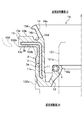
- the sealing device 1 includes an elastic body portion 2 that seals an annular gap between the inner member 101 and the outer member 102.
- the elastic body portion 2 includes a main body portion 11, a seal lip portion 12, a flange portion 13, a side lip portion 14, and a protrusion portion 15.
- the sealing device 1 As shown in FIG. 1, the sealing device 1 according to the first embodiment includes a columnar inner member 101 (for example, a plug tube) that covers the periphery of a spark plug attached to an engine head of an engine (not shown), and an inner member 101. It is a member that seals an annular gap with an outer member 102 (for example, an engine head cover) arranged on the outer side in the radial direction of the engine.
- an outer member 102 for example, an engine head cover
- the sealing device 1 is mainly composed of an elastic body portion 2, a reinforcing ring 3, and a spring member 4.
- the elastic body portion 2 includes a main body portion 11, a seal lip portion 12, a flange portion 13, a side lip portion 14, and a protrusion portion 15.
- the elastic body portion 2 is integrally formed of, for example, various rubber materials.
- the rubber material for example, synthetic rubber such as nitrile rubber (NBR), hydrogenated nitrile rubber (H-NBR), acrylic rubber (ACM), and fluororubber (FKM) can be used.
- the elastic body portion 2 is molded by cross-linking (vulcanization) molding using a molding die. At the time of this cross-linking molding, the reinforcing ring 3 and the spring member 4 arranged in the molding die are cross-linked and bonded to the elastic body portion 2, and each member is integrally formed.
- the main body 11 has an annular shape.
- the main body 11 is arranged in a gap between the outer peripheral surface 101a of the inner member 101 and the inner peripheral surface 102a of the outer member 102.
- the outer peripheral surface 11a of the main body 11 is in contact with the inner peripheral surface 102a of the outer member 102.
- the seal lip portion 12 is a plate-shaped portion extending diagonally upward (anti-sealing target side O) from the end of the main body portion 11 on the sealing target side M toward the inner member 101 side.
- the lip portion 12a of the seal lip portion 12 is in contact with the outer peripheral surface 101a of the inner member 101 in the circumferential direction. As a result, the fluid to be sealed is sealed.
- the flange portion 13 is a plate-shaped portion that projects outward in the radial direction from the end portion of the main body portion 11 on the anti-sealing target side O.
- the flange portion 13 is formed along the main body portion 11 over the entire circumferential direction.
- the back surface (the surface on the sealing target side) 13c of the flange portion 13 is in contact with the end surface 102b of the outer member 102.
- the side lip portion 14 is a plate-shaped portion extending from the end portion of the main body portion 11 on the anti-sealing target side O toward the anti-sealing target side O side (the side separated from the sealing target side M).
- the side lip portion 14 is provided over the entire circumferential direction of the main body portion 11, and the plate thickness becomes thinner toward the tip end. Before assembling, the side lip portion 14 is inclined so as to expand in diameter toward the anti-sealing target side O, as shown in FIG. On the other hand, the side lip portion 14 is pressed by the mating member 103 shown in FIG. 2 to form a seal region between the side lip portion 14 and the protrusion portion 15 to prevent water, muddy water, and the like from entering.
- the mating member is, for example, the upper part of the coil body of the ignition device.
- the protrusion 15 is a protrusion formed over the entire circumferential direction on the surface (the surface on the anti-sealing target side) 13a of the flange portion 13.
- the cross-sectional shape of the protrusion 15 is not particularly limited, but in this embodiment, it is tapered toward the tip. That is, the tip of the protrusion 15 is inclined downward from the surface 13a of the flange 13, and even on the opposite side of the protrusion 15 from the surface 13a of the flange 13, the tip of the protrusion 15 to the groove 13d It slopes down toward the bottom. As a result, the protrusion 15 becomes thicker as it is closer to the base end.
- the bottom portion of the groove portion 13d is deeper than the surface 13a of the flange portion 13.
- the protrusion 15 is formed on the surface 13a of the flange 13 at a position where it can come into contact with the side lip 14.
- the reinforcing ring 3 is a reinforcing member that reinforces the main body portion 11 and the flange portion 13.
- the reinforcing ring 3 is made of, for example, stainless steel, SPCC (cold rolled steel), or the like.
- the reinforcing ring 3 has a side portion 3a arranged inside the main body portion 11 and an overhanging portion 3b arranged inside the flange portion 13, and has an L-shaped cross section.
- the reinforcing ring 3 is manufactured by, for example, pressing or forging.
- the spring member 4 is arranged at the tip of the seal lip 12 in the circumferential direction.
- a garter spring can be used as the spring member 4.
- the spring member 4 applies a tense force in the direction of reducing the diameter at the lip portion 12a of the seal lip 12.
- FIG. 2 is a semi-cross-sectional view at the time of assembly showing the sealing device according to the first embodiment cut by a plane passing through the axis.
- the seal lip portion 12 comes into contact with the inner member 101 in the circumferential direction due to the urging force tilting toward the inner member 101 and the tense force of the spring member 4.
- the sealing device 1 is incorporated, and the surface 14a of the side lip portion 14 is pressed by the mating member 103, so that the tip end side of the side lip portion 14 is tilted in the out-diameter direction, and the back surface 14b of the side lip portion 14 is projected.
- Contact part 15 A seal region is formed between the back surface 14b of the side lip portion 14 and the protrusion 15 to prevent water, muddy water, and the like from entering.
- the elastic body portion 2 by providing the elastic body portion 2 with the seal lip portion 12 and the side lip portion 14, it is possible to achieve both the sealing function of the fluid to be sealed such as oil and the waterproof function, and the number of parts. Can be reduced. Further, when the sealing device 1 is assembled, even if the gap between the mating member 103 and the outer member 102 is small due to the variation in the position of the mating member 103, the side lip portion 14 has a flange portion 13 due to the side lip portion 14 having a large crushing allowance. Since the crushing allowance of the protrusion 15 provided on the surface is also large, the sealing property can be ensured by obtaining a desired surface pressure.
- the protrusion 15 has no crushing allowance or is in a small state, but the side When the lip portion 14 and the mating member 103 come into contact with each other, a desired surface pressure can be obtained and the sealing property can be ensured.
- the flange portion is not provided with a protrusion and the flange portion and the side lip portion are brought into contact with each other, the flange portion and the side lip portion become solid and it becomes difficult to increase the surface pressure.
- the tapered protrusion 15 since the tapered protrusion 15 is provided, the surface pressure between the side lip portion 14 and the protrusion 15 can be increased. Further, due to the variation in the position of the mating member 103 (variation in the axis Z direction), a desired surface pressure can be obtained regardless of whether the gap between the mating member 103 and the outer member 102 is small or large. Therefore, the sealing property between the side lip portion 14 and the protrusion portion 15 can be ensured.
- the sealing device 1A according to the second embodiment will be described.
- the second embodiment is different from the first embodiment in that the protrusion 15A is provided on the side lip portion 14.
- the parts different from the first embodiment will be mainly described.
- a protrusion 15A is provided on the tip end side of the back surface 14b of the side lip portion 14 (the surface of the side lip portion 14 on the flange portion 13 side).
- the protrusion 15A is inclined upward from the tip to the tip of the side lip 14, and the protrusion 15A is from the tip to the back surface 14b of the side lip 14 even on the side close to the base end side of the side lip 14 on the opposite side. Ascending and sloping. As a result, the protrusion 15A becomes thicker as it is closer to the base end.
- the protrusion 15A is formed over the entire circumferential direction.
- the cross-sectional shape of the protrusion 15A is tapered toward the tip.
- the surface (the surface on the anti-sealing target side) 13b of the flange portion 13 is flat.
- a seal region is formed between the protrusion 15A of the side lip portion 14 and the surface 13b of the flange portion 13 to prevent water, muddy water, and the like from entering.
- the protrusion 15A has no crushing allowance or is in a small state, but the side When the lip portion 14 and the mating member 103 come into contact with each other, a desired surface pressure can be obtained and the sealing property can be ensured.
- the elastic body portion 2 by providing the elastic body portion 2 with the seal lip portion 12 and the side lip portion 14, it is possible to achieve both the sealing function of the fluid to be sealed such as oil and the waterproof function, and the number of parts. Can be reduced. Further, when the sealing device 1A is assembled, a desired surface pressure can be obtained regardless of whether the gap between the mating member 103 and the outer member 102 is small or large due to the variation in the position of the mating member 103 (variation in the axis Z direction). , Sealing property can be ensured.
- the third embodiment is different from the first embodiment in that the protrusions 15B are provided at a plurality of positions on the surface 14a of the side lip portion 14 in the extending direction of the side lip portion 14.
- the parts different from the first embodiment will be mainly described.
- the protrusions 15B are formed at a plurality of locations in the extending direction of the side lip portion 14 on the surface 14a (the surface on the semi-sealed target side) of the side lip portion 14 over the circumferential direction.
- a plurality of protrusions 15B are provided at predetermined intervals in the extending direction of the side lip portion 14.
- two protrusions 15B are provided, one on the outside of the side lip portion 14 in the extending direction and the other on the inside of the side lip portion 14 in the extending direction.
- Each of the protrusions 15B has a tapered shape.
- two protrusions 15B are provided, but three or more protrusions 15B may be provided.
- the surface 14a of the side lip portion 14 is the mating. It is pressed by the member 103. Therefore, the tip end side of the side lip portion 14 is tilted in the out-of-diameter direction, the back surface 14b of the side lip portion 14 abuts on the surface 13a of the flange portion 13, and the protrusions 15B and 15B abut on the mating member 103.
- a seal region is formed between the back surface 14b of the side lip portion 14 and the surface 13a of the flange portion 13 to prevent water, muddy water, and the like from entering.
- the surface pressure can be increased without the flange portion 13 and the side lip portion 14 becoming solid.
- the gap between the mating member 103 and the outer member 102 is large due to the variation in the position of the mating member 103, the side lip portion 14 and the mating member 103 come into contact with each other to obtain a desired surface pressure, and the sealing property is obtained. Can be secured.
- the surface pressure can be increased at the position corresponding to the protrusion 15B, and the sealing property is ensured. be able to.
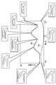
- FIG. 8 shows a case where the horizontal axis is the crushing allowance of the side lip portion 14 and the vertical axis is the maximum value (peak surface pressure) of the surface pressure between the side lip portion 14 and the mating member 103 in the sealing device 1B.
- the graph is shown.
- Graph line 50 shows the value of the sealing device 1B.
- the graph line 150 shows the value of the comparative example which is the configuration in which the protrusion 15 is removed from the sealing device 1 of the first embodiment.
- the balloons attached to the graph lines 50 and 150 indicate the crushed state of the side lip portion 14 when the value is taken.
- the value of the graph line 50 of the sealing device 1B consistently shows a large peak surface pressure as compared with the graph line 150 of the comparative example, regardless of the size of the crushing allowance on the horizontal axis.
- the elastic body portion 2 with the seal lip portion 12 and the side lip portion 14, it is possible to achieve both the sealing function of the fluid to be sealed such as oil and the waterproof function, and the number of parts. Can be reduced.
- a desired surface pressure can be obtained regardless of whether the gap between the mating member 103 and the outer member 102 is small or large due to the variation in the position of the mating member 103 (variation in the axis Z direction). , Sealing property can be ensured.
- the sealing device 1C according to the fourth embodiment will be described.
- the side lip portion 14 is formed with a bent portion 15C bent in the circumferential direction with the back surface 14b side (sealing target side) as the convex side. Therefore, the tip side of the side lip portion 14 with respect to the bent portion 15C is in a state of standing up toward the anti-sealing target side O.
- the surface 14a of the side lip portion 14 is the mating member. Pressed by 103. Therefore, the tip end side of the side lip portion 14 is tilted in the out-of-diameter direction, the convex shape of the bent portion 15C abuts on the front surface 13a of the flange portion 13 on the back surface 14b side of the side lip portion 14, and the back surface 14b of the side lip portion 14 The side abuts on the mating member 103.
- a seal region is formed between the back surface 14b of the side lip portion 14 and the surface 13a of the flange portion 13 to prevent water, muddy water, and the like from entering.
- the surface pressure can be increased without the flange portion 13 and the side lip portion 14 becoming solid.
- the gap between the mating member 103 and the outer member 102 is large due to the variation in the position of the mating member 103, the tip of the side lip portion 14 and the mating member 103 come into contact with each other, so that a desired surface pressure can be obtained. Sealability can be ensured.
- the horizontal axis is the crushing allowance of the side lip portion 14, and the vertical axis is the maximum value (peak surface pressure) of the surface pressure between the side lip portion 14 and the mating member 103.
- the graph is shown.
- the graph line 51 shows the value of the sealing device 1C.
- the graph line 151 shows the value of the comparative example which is the configuration in which the protrusion 15 is removed from the sealing device 1 of the first embodiment.
- the balloons attached to the graph lines 51 and 151 indicate the crushed state of the side lip portion 14 when the value is taken.
- the value of the graph line 51 of the sealing device 1B can consistently maintain a substantially constant peak surface pressure regardless of the size of the crushing allowance on the horizontal axis, as compared with the graph line 151 of the comparative example. .. Therefore, according to the sealing device 1B, the peak surface pressure does not become excessively weak regardless of the size of the crushing allowance.
- the elastic body portion 2 by providing the elastic body portion 2 with the seal lip portion 12 and the side lip portion 14, it is possible to achieve both the sealing function of the fluid to be sealed such as oil and the waterproof function, and the number of parts. Can be reduced.
- sealing device 1C when the sealing device 1C is assembled, a desired surface pressure can be obtained regardless of whether the gap between the mating member 103 and the outer member 102 is small or large due to the variation in the position of the mating member 103 (variation in the axis Z direction). , Sealing property can be ensured.
Landscapes
- Engineering & Computer Science (AREA)
- General Engineering & Computer Science (AREA)
- Mechanical Engineering (AREA)
- Chemical & Material Sciences (AREA)
- Combustion & Propulsion (AREA)
- Gasket Seals (AREA)
- Sealing With Elastic Sealing Lips (AREA)
Abstract
A resilient body portion (2) includes an annular main body portion (11) arranged in a gap, a seal lip portion (12) which is provided extending from the side of the main body portion (11) that is being sealed, and which comes into contact with an inside member (101), a flange portion (13) which is provided extending outward from an edge portion of the main body portion (11) on the opposite side to the side being sealed, and of which a surface on the side being sealed comes into contact with an outside member (102), a side lip portion (14) provided extending from the edge portion of the main body portion (11) on the opposite side to the side being sealed, in a direction moving away from the side being sealed, and a protruding portion (15) formed extending in the circumferential direction on the surface of the flange portion (13) on the opposite side to the side being sealed, characterized in that a rear surface (14b) of the side lip portion (14) is brought into contact with the protruding portion (15) by the side lip portion (14) being pressed by a counterpart member (103) disposed on the opposite side to the side being sealed.
Description
本発明は、密封装置に関する。
The present invention relates to a sealing device.
特許文献1には、エンジンのエンジンヘッドに設けられた点火装置のプラグチューブと、エンジンのヘッドカバーとの環状の隙間を密封する密封装置が開示されている。当該密封装置は、オイルをシールするプラグチューブシール部材と、断面コ字状の防水シール部材とで構成されているが、これらの部材を一体化して部品点数を削減することが求められている。
Patent Document 1 discloses a sealing device that seals an annular gap between a plug tube of an ignition device provided in an engine head of an engine and an annular gap between the head cover of the engine. The sealing device is composed of a plug tube sealing member that seals oil and a waterproof sealing member having a U-shaped cross section, and it is required to integrate these members to reduce the number of parts.
密封装置の一体化にあたり、新たにリップ部を設けることが考えられる。しかし、相手部材(例えば、点火装置のコイル本体上部)の位置のばらつきが大きいため、新たなリップ部の潰し代が小さい場合は所望の面圧が得られるが、潰し代が大きい場合は接触面積が大きくなり(ベタ当りとなり)所望の面圧が得られないおそれがある。
そこで、本発明は、部品点数を削減することができるとともに、サイドリップ部の潰し代が小さい場合のみならず、潰し代が大きい場合であっても所望の面圧を得ることで、シール性を確保できる密封装置を提供することを目的とする。 When integrating the sealing device, it is conceivable to newly provide a lip portion. However, since the position of the mating member (for example, the upper part of the coil body of the ignition device) varies widely, a desired surface pressure can be obtained when the crushing allowance of the new lip portion is small, but the contact area is obtained when the crushing allowance is large. May become large (become solid) and the desired surface pressure may not be obtained.
Therefore, according to the present invention, the number of parts can be reduced, and the sealing property can be improved by obtaining a desired surface pressure not only when the crushing allowance of the side lip portion is small but also when the crushing allowance is large. It is an object of the present invention to provide a sealing device that can be secured.
本発明は、内側部材と外側部材との間の環状の隙間を密封する弾性体部を備える密封装置であって、前記弾性体部は、前記隙間に配置される環状の本体部と、前記本体部の密封対象側から延設され、前記内側部材に接触するシールリップ部と、前記本体部の反密封対象側の端部から外側に延設され、密封対象側の面が前記外側部材に接触するフランジ部と、前記本体部の反密封対象側の端部から密封対象側から離間する方向に延設されたサイドリップ部と、前記フランジ部の反密封対象側の面に周方向に亘って形成された突起部と、を有し、反密封対象側に配置された相手部材によって前記サイドリップ部が押圧されることにより、前記サイドリップ部の裏面が前記突起部に接触することを特徴とする。
The present invention is a sealing device including an elastic body portion that seals an annular gap between an inner member and an outer member, wherein the elastic body portion includes an annular main body portion arranged in the gap and the main body. The seal lip portion extending from the sealing target side of the portion and contacting the inner member and the surface extending outward from the end of the main body portion on the anti-sealing target side, and the surface on the sealing target side contacts the outer member. Flange portion, side lip portion extending in a direction away from the end of the main body portion on the anti-sealing target side, and the surface of the flange portion on the anti-sealing target side in the circumferential direction. It is characterized in that the back surface of the side lip portion comes into contact with the protrusion by pressing the side lip portion with the formed protrusion and the mating member arranged on the anti-sealing target side. To do.
また、本発明は、内側部材と外側部材との間の環状の隙間を密封する弾性体部を備える密封装置であって、前記弾性体部は、前記隙間に配置される環状の本体部と、前記本体部の密封対象側から延設され、前記内側部材に接触するシールリップ部と、前記本体部の反密封対象側の端部から外側に延設され、密封対象側の面が前記外側部材に接触するフランジ部と、前記本体部の反密封対象側の端部から密封対象側から離間する方向に延設されたサイドリップ部と、前記サイドリップ部の裏面に周方向に亘って形成された突起部と、を有し、反密封対象側に配置された相手部材によって前記サイドリップ部が押圧されることにより、前記突起部が前記フランジ部に接触することを特徴とする。
Further, the present invention is a sealing device including an elastic body portion that seals an annular gap between the inner member and the outer member, wherein the elastic body portion includes an annular main body portion arranged in the gap and an annular main body portion. The seal lip portion extending from the sealing target side of the main body portion and coming into contact with the inner member and the sealing lip portion extending outward from the end of the main body portion on the anti-sealing target side, and the surface on the sealing target side is the outer member. A flange portion that comes into contact with the surface, a side lip portion that extends from the end of the main body portion on the anti-sealing target side in a direction away from the sealing target side, and a side lip portion that is formed on the back surface of the side lip portion in the circumferential direction. It is characterized in that the side lip portion is pressed by a mating member arranged on the anti-sealing target side, so that the protrusion portion comes into contact with the flange portion.
また、本発明は、内側部材と外側部材との間の環状の隙間を密封する弾性体部を備える密封装置であって、前記弾性体部は、前記隙間に配置される環状の本体部と、前記本体部の密封対象側から延設され、前記内側部材に接触するシールリップ部と、前記本体部の反密封対象側の端部から外側に延設され、密封対象側の面が前記外側部材に接触するフランジ部と、前記本体部の反密封対象側の端部から密封対象側から離間する方向に延設されたサイドリップ部と、前記サイドリップ部の表面における当該サイドリップ部の延出方向の複数個所に周方向に亘って形成された突起部と、を有し、反密封対象側に配置された相手部材によって前記サイドリップ部が押圧されることにより、前記サイドリップ部の裏面が前記フランジ部の反密封対象側の面に接触し、前記突起部は前記相手部材に接触することを特徴とする。
Further, the present invention is a sealing device including an elastic body portion that seals an annular gap between the inner member and the outer member, wherein the elastic body portion includes an annular main body portion arranged in the gap and an annular main body portion. The seal lip portion extending from the sealing target side of the main body portion and coming into contact with the inner member and the sealing lip portion extending outward from the end of the main body portion on the anti-sealing target side, and the surface on the sealing target side is the outer member. A flange portion that comes into contact with the main body portion, a side lip portion that extends in a direction away from the sealing target side from the end of the main body portion on the anti-sealing target side, and an extension of the side lip portion on the surface of the side lip portion. The side lip portion is pressed by a mating member arranged on the anti-sealing target side, which has protrusions formed in a plurality of directions in the circumferential direction, so that the back surface of the side lip portion is pressed. The flange portion comes into contact with the surface of the flange portion on the anti-sealing target side, and the protrusion portion comes into contact with the mating member.
また、本発明は、内側部材と外側部材との間の環状の隙間を密封する弾性体部を備える密封装置であって、前記弾性体部は、前記隙間に配置される環状の本体部と、前記本体部の密封対象側から延設され、前記内側部材に接触するシールリップ部と、前記本体部の反密封対象側の端部から外側に延設され、密封対象側の面が前記外側部材に接触するフランジ部と、前記本体部の反密封対象側の端部から密封対象側から離間する方向に延設されたサイドリップ部と、前記サイドリップ部の裏面側を凸側として周方向に亘って屈曲している屈曲部と、を有し、反密封対象側に配置された相手部材によって前記サイドリップ部が押圧されることにより、前記屈曲部が前記フランジ部に接触することを特徴とする。
Further, the present invention is a sealing device including an elastic body portion that seals an annular gap between an inner member and an outer member, wherein the elastic body portion includes an annular main body portion arranged in the gap and an annular main body portion. The seal lip portion extending from the sealing target side of the main body portion and coming into contact with the inner member and the sealing lip portion extending outward from the end of the main body portion on the anti-sealing target side, and the surface on the sealing target side is the outer member. A flange portion that comes into contact with the main body portion, a side lip portion that extends in a direction away from the sealing target side from the end of the main body portion on the anti-sealing target side, and a circumferential direction with the back surface side of the side lip portion as a convex side. It is characterized in that the bent portion has a bent portion that is bent over the entire surface, and the side lip portion is pressed by a mating member arranged on the anti-sealing target side so that the bent portion comes into contact with the flange portion. To do.
本発明によれば、弾性体部にシールリップ部及びサイドリップ部を設けることにより、オイル等の密封対象流体のシール機能と、防水機能の両立を図ることができるとともに、部品点数を削減することができる。また、密封装置の組み込み時に、相手部材の位置のばらつきにより、相手部材とシール部分との隙間が小さい場合、サイドリップ部がフランジ部に設けられた突起部に接触するので、所望の面圧を得てシール性を確保することができる。また、相手部材とシール部分との隙間が大きい場合、相手部材にサイドリップ部が接触するので、所望の面圧を得てシール性を確保することができる。
According to the present invention, by providing the seal lip portion and the side lip portion on the elastic body portion, it is possible to achieve both the sealing function of the fluid to be sealed such as oil and the waterproof function, and to reduce the number of parts. Can be done. Further, when the sealing device is assembled, if the gap between the mating member and the sealing portion is small due to the variation in the position of the mating member, the side lip portion comes into contact with the protrusion provided on the flange portion, so that a desired surface pressure can be obtained. It is possible to secure the sealing property. Further, when the gap between the mating member and the sealing portion is large, the side lip portion comes into contact with the mating member, so that a desired surface pressure can be obtained and the sealing property can be ensured.
または、サイドリップ部に突起部がある場合も、相手部材の位置のばらつきにより、相手部材とシール部分との隙間が小さい場合、サイドリップ部の突起部がフランジ部に接触するので、所望の面圧を得てシール性を確保することができる。また、相手部材とシール部分との隙間が大きい場合、相手部材にサイドリップ部が接触するので、所望の面圧を得てシール性を確保することができる。
Alternatively, even if the side lip portion has a protrusion, if the gap between the mating member and the seal portion is small due to the variation in the position of the mating member, the protruding portion of the side lip portion comes into contact with the flange portion, so that the desired surface is formed. It is possible to obtain pressure and secure the sealing property. Further, when the gap between the mating member and the sealing portion is large, the side lip portion comes into contact with the mating member, so that a desired surface pressure can be obtained and the sealing property can be ensured.
または、サイドリップ部の表面に複数の突起部がある場合でも、相手部材の位置のばらつきにより、相手部材とシール部分との隙間が小さい場合、サイドリップ部の複数の突起部が相手部材に接触するので、所望の面圧を得てシール性を確保することができる。また、相手部材とシール部分との隙間が大きい場合、相手部材にサイドリップ部が接触するので、所望の面圧を得てシール性を確保することができる。
Alternatively, even if there are a plurality of protrusions on the surface of the side lip portion, if the gap between the mating member and the seal portion is small due to the variation in the position of the mating member, the plurality of protrusions of the side lip portion come into contact with the mating member. Therefore, a desired surface pressure can be obtained and the sealing property can be ensured. Further, when the gap between the mating member and the sealing portion is large, the side lip portion comes into contact with the mating member, so that a desired surface pressure can be obtained and the sealing property can be ensured.
または、サイドリップ部の裏面側を凸側として周方向に亘って屈曲している屈曲部がある場合でも、相手部材の位置のばらつきにより、相手部材とシール部分との隙間が小さい場合、屈曲部の凸形状がフランジ部に接触するので、所望の面圧を得てシール性を確保することができる。また、相手部材とシール部分との隙間が大きい場合、相手部材にサイドリップ部が接触するので、所望の面圧を得てシール性を確保することができる。
Alternatively, even if there is a bent portion that is bent in the circumferential direction with the back surface side of the side lip portion as the convex side, if the gap between the mating member and the seal portion is small due to the variation in the position of the mating member, the bent portion. Since the convex shape of the above comes into contact with the flange portion, a desired surface pressure can be obtained and the sealing property can be ensured. Further, when the gap between the mating member and the sealing portion is large, the side lip portion comes into contact with the mating member, so that a desired surface pressure can be obtained and the sealing property can be ensured.
本発明に係る密封装置によれば、部品点数を少なくすることができるとともに、サイドリップ部の潰し代が小さい場合のみならず、潰し代が大きい場合であっても所望の面圧を得ることで、シール性を確保できる。
According to the sealing device according to the present invention, the number of parts can be reduced, and a desired surface pressure can be obtained not only when the crushing allowance of the side lip portion is small but also when the crushing allowance is large. , Sealing property can be secured.
以下の説明において、「表面」は「裏面」と反対側の面という意味である。図1に示すように、実施形態に係る密封装置1は、内側部材101と外側部材102との間の環状の隙間を密封する弾性体部2を備えている。弾性体部2は、本体部11と、シールリップ部12と、フランジ部13と、サイドリップ部14と、突起部15とを備えている。
In the following explanation, "front side" means the side opposite to "back side". As shown in FIG. 1, the sealing device 1 according to the embodiment includes an elastic body portion 2 that seals an annular gap between the inner member 101 and the outer member 102. The elastic body portion 2 includes a main body portion 11, a seal lip portion 12, a flange portion 13, a side lip portion 14, and a protrusion portion 15.
図2に示すように、反密封対象側Oに配置された相手部材103によってサイドリップ部14が押圧されることにより、サイドリップ部14の裏面14bが突起部15に接触する。このように、弾性体部2にシールリップ部12とサイドリップ部14を設けることにより、部品点数を削減することができる。また、密封装置1の組み込み時に、相手部材103の位置のばらつきによって、相手部材103と外側部材102との隙間が小さい場合でも、潰し代の大きいサイドリップ部14がフランジ部13に設けられた突起部15を押圧して突起部15の潰し代を大きくするので、所望の面圧を得ることで、シール性を確保することができる。また、図3に示すように、相手部材103と外側部材102との隙間が大きくて潰し代の小さいサイドリップ部14の押圧によって突起部15の潰し代がない、又は潰し代が小さい場合でも、所望の面圧を得ることで、シール性を確保することができる。以下、実施例1~4について詳細に説明する。
As shown in FIG. 2, when the side lip portion 14 is pressed by the mating member 103 arranged on the anti-sealing target side O, the back surface 14b of the side lip portion 14 comes into contact with the protrusion portion 15. By providing the elastic body portion 2 with the seal lip portion 12 and the side lip portion 14 in this way, the number of parts can be reduced. Further, when the sealing device 1 is assembled, even if the gap between the mating member 103 and the outer member 102 is small due to the variation in the position of the mating member 103, the side lip portion 14 having a large crushing allowance is provided on the flange portion 13. Since the portion 15 is pressed to increase the crushing allowance of the protrusion portion 15, the sealing property can be ensured by obtaining a desired surface pressure. Further, as shown in FIG. 3, even when the protrusion portion 15 has no crushing allowance or the crushing allowance is small due to the pressing of the side lip portion 14 having a large gap between the mating member 103 and the outer member 102 and a small crushing allowance. By obtaining a desired surface pressure, the sealing property can be ensured. Hereinafter, Examples 1 to 4 will be described in detail.
[実施例1]
実施例1に係る密封装置1は、図1に示すように、図示しないエンジンのエンジンヘッドに取り付けられている点火プラグの周囲を覆う柱状の内側部材101(例えば、プラグチューブ)と、内側部材101の径方向外側に配置される外側部材102(例えば、エンジンのヘッドカバー)との間の環状の隙間を密封する部材である。密封装置1は、本実施例ではプラグチューブシールとして用いている場合を例示するが、インジェクターポンプシール等他の用途で用いてもよい。密封装置1は、弾性体部2と、補強環3と、ばね部材4とで主に構成されている。 [Example 1]
As shown in FIG. 1, thesealing device 1 according to the first embodiment includes a columnar inner member 101 (for example, a plug tube) that covers the periphery of a spark plug attached to an engine head of an engine (not shown), and an inner member 101. It is a member that seals an annular gap with an outer member 102 (for example, an engine head cover) arranged on the outer side in the radial direction of the engine. Although the sealing device 1 is used as a plug tube seal in this embodiment, it may be used for other purposes such as an injector pump seal. The sealing device 1 is mainly composed of an elastic body portion 2, a reinforcing ring 3, and a spring member 4.
実施例1に係る密封装置1は、図1に示すように、図示しないエンジンのエンジンヘッドに取り付けられている点火プラグの周囲を覆う柱状の内側部材101(例えば、プラグチューブ)と、内側部材101の径方向外側に配置される外側部材102(例えば、エンジンのヘッドカバー)との間の環状の隙間を密封する部材である。密封装置1は、本実施例ではプラグチューブシールとして用いている場合を例示するが、インジェクターポンプシール等他の用途で用いてもよい。密封装置1は、弾性体部2と、補強環3と、ばね部材4とで主に構成されている。 [Example 1]
As shown in FIG. 1, the
弾性体部2は、本体部11と、シールリップ部12と、フランジ部13と、サイドリップ部14と、突起部15とを備えている。弾性体部2は、例えば、各種ゴム材で一体形成されている。ゴム材としては、例えば、ニトリルゴム(NBR)、水素添加ニトリルゴム(H-NBR)、アクリルゴム(ACM)、フッ素ゴム(FKM)等の合成ゴムを用いることができる。
弾性体部2は、成形型を用いて架橋(加硫)成型によって成形される。この架橋成型の際、成形型の中に配置された補強環3及びばね部材4が弾性体部2に架橋接着され、各部材が一体的に形成される。 Theelastic body portion 2 includes a main body portion 11, a seal lip portion 12, a flange portion 13, a side lip portion 14, and a protrusion portion 15. The elastic body portion 2 is integrally formed of, for example, various rubber materials. As the rubber material, for example, synthetic rubber such as nitrile rubber (NBR), hydrogenated nitrile rubber (H-NBR), acrylic rubber (ACM), and fluororubber (FKM) can be used.
Theelastic body portion 2 is molded by cross-linking (vulcanization) molding using a molding die. At the time of this cross-linking molding, the reinforcing ring 3 and the spring member 4 arranged in the molding die are cross-linked and bonded to the elastic body portion 2, and each member is integrally formed.
弾性体部2は、成形型を用いて架橋(加硫)成型によって成形される。この架橋成型の際、成形型の中に配置された補強環3及びばね部材4が弾性体部2に架橋接着され、各部材が一体的に形成される。 The
The
本体部11は、円環状を呈する。本体部11は、内側部材101の外周面101aと外側部材102の内周面102aとの間の隙間に配置されている。本体部11の外周面11aは、外側部材102の内周面102aに接触している。
シールリップ部12は、本体部11の密封対象側Mの端部から、内側部材101側に向けて斜め上側(反密封対象側O)に延設された板状部である。シールリップ部12のリップ部12aは、内側部材101の外周面101aに周方向に亘って接触している。これにより、密封対象流体がシールされる。 Themain body 11 has an annular shape. The main body 11 is arranged in a gap between the outer peripheral surface 101a of the inner member 101 and the inner peripheral surface 102a of the outer member 102. The outer peripheral surface 11a of the main body 11 is in contact with the inner peripheral surface 102a of the outer member 102.
Theseal lip portion 12 is a plate-shaped portion extending diagonally upward (anti-sealing target side O) from the end of the main body portion 11 on the sealing target side M toward the inner member 101 side. The lip portion 12a of the seal lip portion 12 is in contact with the outer peripheral surface 101a of the inner member 101 in the circumferential direction. As a result, the fluid to be sealed is sealed.
シールリップ部12は、本体部11の密封対象側Mの端部から、内側部材101側に向けて斜め上側(反密封対象側O)に延設された板状部である。シールリップ部12のリップ部12aは、内側部材101の外周面101aに周方向に亘って接触している。これにより、密封対象流体がシールされる。 The
The
フランジ部13は、本体部11の反密封対象側Oの端部から、径方向外側に張り出す板状部である。フランジ部13は、本体部11に沿って周方向全体に亘って形成されている。フランジ部13の裏面(密封対象側の面)13cは、外側部材102の端面102bに接触している。
サイドリップ部14は、本体部11の反密封対象側Oの端部から、反密封対象側O側(密封対象側Mから離間する側)に向けて延設された板状部である。サイドリップ部14は、本体部11の周方向全体に亘って設けられ、先端に向かうにつれて板厚が薄くなっている。サイドリップ部14は、組み込み前においては図1に示すように、反密封対象側Oに拡径する形状に傾斜している。一方、サイドリップ部14は、図2に示す相手部材103によって押圧されることにより、突起部15との間で水、泥水等の侵入を防ぐシール領域を形成する。相手部材は、例えば、点火装置のコイル本体上部である。 Theflange portion 13 is a plate-shaped portion that projects outward in the radial direction from the end portion of the main body portion 11 on the anti-sealing target side O. The flange portion 13 is formed along the main body portion 11 over the entire circumferential direction. The back surface (the surface on the sealing target side) 13c of the flange portion 13 is in contact with the end surface 102b of the outer member 102.
Theside lip portion 14 is a plate-shaped portion extending from the end portion of the main body portion 11 on the anti-sealing target side O toward the anti-sealing target side O side (the side separated from the sealing target side M). The side lip portion 14 is provided over the entire circumferential direction of the main body portion 11, and the plate thickness becomes thinner toward the tip end. Before assembling, the side lip portion 14 is inclined so as to expand in diameter toward the anti-sealing target side O, as shown in FIG. On the other hand, the side lip portion 14 is pressed by the mating member 103 shown in FIG. 2 to form a seal region between the side lip portion 14 and the protrusion portion 15 to prevent water, muddy water, and the like from entering. The mating member is, for example, the upper part of the coil body of the ignition device.
サイドリップ部14は、本体部11の反密封対象側Oの端部から、反密封対象側O側(密封対象側Mから離間する側)に向けて延設された板状部である。サイドリップ部14は、本体部11の周方向全体に亘って設けられ、先端に向かうにつれて板厚が薄くなっている。サイドリップ部14は、組み込み前においては図1に示すように、反密封対象側Oに拡径する形状に傾斜している。一方、サイドリップ部14は、図2に示す相手部材103によって押圧されることにより、突起部15との間で水、泥水等の侵入を防ぐシール領域を形成する。相手部材は、例えば、点火装置のコイル本体上部である。 The
The
突起部15は、フランジ部13の表面(反密封対象側の面)13aにおいて周方向全体に亘って形成された突起である。突起部15の断面形状は特に制限されないが、本実施例では先端に向けて先細りとなっている。すなわち、突起部15の先端部からフランジ部13の表面13aまでは下り傾斜しており、フランジ部13の表面13a側とは突起部15の反対側でも、突起部15の先端部から溝部13dの底部に向けて下り傾斜している。これによって、突起部15は基端部に近い部分程厚くなっている。そして、溝部13dの底部は、フランジ部13の表面13aよりも深くなっている。突起部15は、フランジ部13の表面13aにおいて、サイドリップ部14と接触可能な位置に形成されている。
The protrusion 15 is a protrusion formed over the entire circumferential direction on the surface (the surface on the anti-sealing target side) 13a of the flange portion 13. The cross-sectional shape of the protrusion 15 is not particularly limited, but in this embodiment, it is tapered toward the tip. That is, the tip of the protrusion 15 is inclined downward from the surface 13a of the flange 13, and even on the opposite side of the protrusion 15 from the surface 13a of the flange 13, the tip of the protrusion 15 to the groove 13d It slopes down toward the bottom. As a result, the protrusion 15 becomes thicker as it is closer to the base end. The bottom portion of the groove portion 13d is deeper than the surface 13a of the flange portion 13. The protrusion 15 is formed on the surface 13a of the flange 13 at a position where it can come into contact with the side lip 14.
フランジ部13において、突起部15とサイドリップ部14との間に溝部13dが設けられている。溝部13dの大きさ、深さを調節することで、相手部材103に押圧された時のサイドリップ部14の傾倒具合を調節することができる。
補強環3は、本体部11及びフランジ部13を補強する補強部材である。補強環3は、例えば、ステンレス鋼、SPCC(冷間圧延鋼)などで形成されたものである。補強環3は、本体部11の内部に配置される側部3aと、フランジ部13の内部に配置される張出部3bとを有し、断面L字状を呈する。補強環3は、例えば、プレス加工や鍛造によって製造される。 In theflange portion 13, a groove portion 13d is provided between the protrusion portion 15 and the side lip portion 14. By adjusting the size and depth of the groove portion 13d, it is possible to adjust the degree of inclination of the side lip portion 14 when pressed by the mating member 103.
The reinforcingring 3 is a reinforcing member that reinforces the main body portion 11 and the flange portion 13. The reinforcing ring 3 is made of, for example, stainless steel, SPCC (cold rolled steel), or the like. The reinforcing ring 3 has a side portion 3a arranged inside the main body portion 11 and an overhanging portion 3b arranged inside the flange portion 13, and has an L-shaped cross section. The reinforcing ring 3 is manufactured by, for example, pressing or forging.
補強環3は、本体部11及びフランジ部13を補強する補強部材である。補強環3は、例えば、ステンレス鋼、SPCC(冷間圧延鋼)などで形成されたものである。補強環3は、本体部11の内部に配置される側部3aと、フランジ部13の内部に配置される張出部3bとを有し、断面L字状を呈する。補強環3は、例えば、プレス加工や鍛造によって製造される。 In the
The reinforcing
ばね部材4は、シールリップ12の先端部において周方向に亘って配置されている。ばね部材4として、例えば、ガータースプリングを用いることができる。ばね部材4は、シールリップ12のリップ部12aにおいて縮径する方向に緊迫力を付与している。
The spring member 4 is arranged at the tip of the seal lip 12 in the circumferential direction. As the spring member 4, for example, a garter spring can be used. The spring member 4 applies a tense force in the direction of reducing the diameter at the lip portion 12a of the seal lip 12.
次に、実施例1の作用効果について説明する。図2は、実施例1に係る密封装置を、軸心を通る平面で切断して示す組み込み時の半断面図である。シールリップ部12は、内側部材101側に傾倒する付勢力及びばね部材4の緊迫力で内側部材101と周方向に亘って接触する。これにより、密封対象流体がシールされる。
また、密封装置1が組み込まれ、サイドリップ部14の表面14aが相手部材103により押圧されることにより、サイドリップ部14の先端側が径外方向に傾倒され、サイドリップ部14の裏面14bが突起部15に接触する。サイドリップ部14の裏面14bと突起部15との間で水、泥水等の侵入を防ぐシール領域が形成される。 Next, the action and effect of Example 1 will be described. FIG. 2 is a semi-cross-sectional view at the time of assembly showing the sealing device according to the first embodiment cut by a plane passing through the axis. Theseal lip portion 12 comes into contact with the inner member 101 in the circumferential direction due to the urging force tilting toward the inner member 101 and the tense force of the spring member 4. As a result, the fluid to be sealed is sealed.
Further, thesealing device 1 is incorporated, and the surface 14a of the side lip portion 14 is pressed by the mating member 103, so that the tip end side of the side lip portion 14 is tilted in the out-diameter direction, and the back surface 14b of the side lip portion 14 is projected. Contact part 15. A seal region is formed between the back surface 14b of the side lip portion 14 and the protrusion 15 to prevent water, muddy water, and the like from entering.
また、密封装置1が組み込まれ、サイドリップ部14の表面14aが相手部材103により押圧されることにより、サイドリップ部14の先端側が径外方向に傾倒され、サイドリップ部14の裏面14bが突起部15に接触する。サイドリップ部14の裏面14bと突起部15との間で水、泥水等の侵入を防ぐシール領域が形成される。 Next, the action and effect of Example 1 will be described. FIG. 2 is a semi-cross-sectional view at the time of assembly showing the sealing device according to the first embodiment cut by a plane passing through the axis. The
Further, the
実施例1によれば、弾性体部2にシールリップ部12及びサイドリップ部14を設けることにより、オイル等の密封対象流体のシール機能と、防水機能の両立を図ることができるとともに、部品点数を削減することができる。また、密封装置1の組み込み時に、相手部材103の位置のばらつきによって相手部材103と外側部材102との隙間が小さい場合でも、潰し代の大きいサイドリップ部14によって、サイドリップ部14がフランジ部13に設けられた突起部15の潰し代も大きくなるので、所望の面圧を得ることで、シール性を確保することができる。
According to the first embodiment, by providing the elastic body portion 2 with the seal lip portion 12 and the side lip portion 14, it is possible to achieve both the sealing function of the fluid to be sealed such as oil and the waterproof function, and the number of parts. Can be reduced. Further, when the sealing device 1 is assembled, even if the gap between the mating member 103 and the outer member 102 is small due to the variation in the position of the mating member 103, the side lip portion 14 has a flange portion 13 due to the side lip portion 14 having a large crushing allowance. Since the crushing allowance of the protrusion 15 provided on the surface is also large, the sealing property can be ensured by obtaining a desired surface pressure.
また、図3に示すように、相手部材103の位置のばらつきによって相手部材103と外側部材102との隙間が大きい場合には、突起部15は潰し代がない、あるいは小さい状態となるが、サイドリップ部14と相手部材103とが当接することで所望の面圧が得られ、シール性を確保することができる。
ここで、仮に、フランジ部に突起部を設けず、当該フランジ部とサイドリップ部とを接触させると、フランジ部とサイドリップ部とがベタ当りとなり面圧を大きくすることが困難となる。しかし、本実施例によれば、先細りとなる突起部15を設けているため、サイドリップ部14と突起部15との面圧を大きくすることができる。また、相手部材103の位置のばらつき(軸心Z方向のばらつき)によって、相手部材103と外側部材102との隙間が小さくても大きくても所望の面圧を得ることができる。よって、サイドリップ部14と突起部15との間のシール性を確保することができる。 Further, as shown in FIG. 3, when the gap between themating member 103 and the outer member 102 is large due to the variation in the position of the mating member 103, the protrusion 15 has no crushing allowance or is in a small state, but the side When the lip portion 14 and the mating member 103 come into contact with each other, a desired surface pressure can be obtained and the sealing property can be ensured.
Here, if the flange portion is not provided with a protrusion and the flange portion and the side lip portion are brought into contact with each other, the flange portion and the side lip portion become solid and it becomes difficult to increase the surface pressure. However, according to this embodiment, since the taperedprotrusion 15 is provided, the surface pressure between the side lip portion 14 and the protrusion 15 can be increased. Further, due to the variation in the position of the mating member 103 (variation in the axis Z direction), a desired surface pressure can be obtained regardless of whether the gap between the mating member 103 and the outer member 102 is small or large. Therefore, the sealing property between the side lip portion 14 and the protrusion portion 15 can be ensured.
ここで、仮に、フランジ部に突起部を設けず、当該フランジ部とサイドリップ部とを接触させると、フランジ部とサイドリップ部とがベタ当りとなり面圧を大きくすることが困難となる。しかし、本実施例によれば、先細りとなる突起部15を設けているため、サイドリップ部14と突起部15との面圧を大きくすることができる。また、相手部材103の位置のばらつき(軸心Z方向のばらつき)によって、相手部材103と外側部材102との隙間が小さくても大きくても所望の面圧を得ることができる。よって、サイドリップ部14と突起部15との間のシール性を確保することができる。 Further, as shown in FIG. 3, when the gap between the
Here, if the flange portion is not provided with a protrusion and the flange portion and the side lip portion are brought into contact with each other, the flange portion and the side lip portion become solid and it becomes difficult to increase the surface pressure. However, according to this embodiment, since the tapered
[実施例2]
次に、実施例2に係る密封装置1Aについて説明する。実施例2では、サイドリップ部14に突起部15Aを設ける点で実施例1と相違する。実施例2では、実施例1と相違する部分を中心に説明する。 [Example 2]
Next, thesealing device 1A according to the second embodiment will be described. The second embodiment is different from the first embodiment in that the protrusion 15A is provided on the side lip portion 14. In the second embodiment, the parts different from the first embodiment will be mainly described.
次に、実施例2に係る密封装置1Aについて説明する。実施例2では、サイドリップ部14に突起部15Aを設ける点で実施例1と相違する。実施例2では、実施例1と相違する部分を中心に説明する。 [Example 2]
Next, the
図4に示すように、サイドリップ部14の裏面14b(サイドリップ部14のフランジ部13側の面)の先端側には、突起部15Aが設けられている。突起部15Aは先端部からサイドリップ部14の先端まで上り傾斜しており、その反対側のサイドリップ部14の基端側に近い側でも突起部15Aは先端部からサイドリップ部14の裏面14bまで昇り傾斜している。これによって、突起部15Aは基端部に近い部分程厚くなっている。突起部15Aは、周方向全体に亘って形成されている。突起部15Aの断面形状は、先端に向けて先細りとなっている。フランジ部13の表面(反密封対象側の面)13bは、平坦になっている。
As shown in FIG. 4, a protrusion 15A is provided on the tip end side of the back surface 14b of the side lip portion 14 (the surface of the side lip portion 14 on the flange portion 13 side). The protrusion 15A is inclined upward from the tip to the tip of the side lip 14, and the protrusion 15A is from the tip to the back surface 14b of the side lip 14 even on the side close to the base end side of the side lip 14 on the opposite side. Ascending and sloping. As a result, the protrusion 15A becomes thicker as it is closer to the base end. The protrusion 15A is formed over the entire circumferential direction. The cross-sectional shape of the protrusion 15A is tapered toward the tip. The surface (the surface on the anti-sealing target side) 13b of the flange portion 13 is flat.
図5に示すように、密封装置1が組み込まれ、相手部材103の位置のばらつきによって相手部材103と外側部材102との隙間が小さく潰し代が大きい場合は、サイドリップ部14の表面14aが相手部材103により押圧されることにより、サイドリップ部14の先端側が径外方向に傾倒され、サイドリップ部14の突起部15Aがフランジ部13の表面13bに当接して突起部15Aの潰し代が大きくなる。これにより、サイドリップ部14の突起部15Aとフランジ部13の表面13bとの間で水、泥水等の侵入を防ぐシール領域が形成される。また、実施例1と同様に、相手部材103の位置のばらつきによって相手部材103と外側部材102との隙間が大きい場合には、突起部15Aは潰し代がない、あるいは小さい状態となるが、サイドリップ部14と相手部材103とが当接することで所望の面圧が得られ、シール性を確保することができる。
As shown in FIG. 5, when the sealing device 1 is incorporated and the gap between the mating member 103 and the outer member 102 is small and the crushing allowance is large due to the variation in the position of the mating member 103, the surface 14a of the side lip portion 14 is the mating. By being pressed by the member 103, the tip end side of the side lip portion 14 is tilted in the out-of-diameter direction, the protrusion 15A of the side lip portion 14 comes into contact with the surface 13b of the flange portion 13, and the crushing allowance of the protrusion 15A is large. Become. As a result, a seal region is formed between the protrusion 15A of the side lip portion 14 and the surface 13b of the flange portion 13 to prevent water, muddy water, and the like from entering. Further, as in the first embodiment, when the gap between the mating member 103 and the outer member 102 is large due to the variation in the position of the mating member 103, the protrusion 15A has no crushing allowance or is in a small state, but the side When the lip portion 14 and the mating member 103 come into contact with each other, a desired surface pressure can be obtained and the sealing property can be ensured.
実施例2によれば、弾性体部2にシールリップ部12及びサイドリップ部14を設けることにより、オイル等の密封対象流体のシール機能と、防水機能の両立を図ることができるとともに、部品点数を削減することができる。また、密封装置1Aの組み込み時に、相手部材103の位置のばらつき(軸心Z方向のばらつき)によって相手部材103と外側部材102との隙間が小さくても大きくても所望の面圧を得ることで、シール性を確保することができる。
According to the second embodiment, by providing the elastic body portion 2 with the seal lip portion 12 and the side lip portion 14, it is possible to achieve both the sealing function of the fluid to be sealed such as oil and the waterproof function, and the number of parts. Can be reduced. Further, when the sealing device 1A is assembled, a desired surface pressure can be obtained regardless of whether the gap between the mating member 103 and the outer member 102 is small or large due to the variation in the position of the mating member 103 (variation in the axis Z direction). , Sealing property can be ensured.
[実施例3]
次に、実施例3に係る密封装置1Bについて説明する。実施例3では、サイドリップ部14の表面14aにおけるサイドリップ部14の延出方向の複数個所に突起部15Bを設ける点で実施例1と相違する。実施例3では、実施例1と相違する部分を中心に説明する。 [Example 3]
Next, thesealing device 1B according to the third embodiment will be described. The third embodiment is different from the first embodiment in that the protrusions 15B are provided at a plurality of positions on the surface 14a of the side lip portion 14 in the extending direction of the side lip portion 14. In the third embodiment, the parts different from the first embodiment will be mainly described.
次に、実施例3に係る密封装置1Bについて説明する。実施例3では、サイドリップ部14の表面14aにおけるサイドリップ部14の延出方向の複数個所に突起部15Bを設ける点で実施例1と相違する。実施例3では、実施例1と相違する部分を中心に説明する。 [Example 3]
Next, the
図6に示すように、突起部15Bは、サイドリップ部14の表面14a(半密封対象側の面)におけるサイドリップ部14の延出方向の複数個所に周方向に亘って形成されている。突起部15Bは、サイドリップ部14の延出方向に互いに所定間隔を空けて複数個設けられている。本実施例では、2つの突起部15Bが、一つはサイドリップ部14の延出方向の外側に、他の一つはサイドリップ部14の延出方向の内側に設けられている。いずれの突起部15Bも先細り形状をしている。なお、本実施例では突起部15Bを2つ設けたが、突起部15Bを3つ以上設けてもよい。
As shown in FIG. 6, the protrusions 15B are formed at a plurality of locations in the extending direction of the side lip portion 14 on the surface 14a (the surface on the semi-sealed target side) of the side lip portion 14 over the circumferential direction. A plurality of protrusions 15B are provided at predetermined intervals in the extending direction of the side lip portion 14. In this embodiment, two protrusions 15B are provided, one on the outside of the side lip portion 14 in the extending direction and the other on the inside of the side lip portion 14 in the extending direction. Each of the protrusions 15B has a tapered shape. In this embodiment, two protrusions 15B are provided, but three or more protrusions 15B may be provided.
図7に示すように、密封装置1Bが組み込まれ、相手部材103の位置のばらつきによって相手部材103と外側部材102との隙間が小さく潰し代が大きい場合は、サイドリップ部14の表面14aが相手部材103により押圧される。よって、サイドリップ部14の先端側が径外方向に傾倒されて、サイドリップ部14の裏面14bがフランジ部13の表面13aに当接し、突起部15B,15Bは相手部材103に当接する。これにより、サイドリップ部14の裏面14bとフランジ部13の表面13aとの間で水、泥水等の侵入を防ぐシール領域が形成される。この際、突起部15Bに対応する位置では、フランジ部13とサイドリップ部14とがベタ当りとならずに面圧を大きくすることができる。また、相手部材103の位置のばらつきによって相手部材103と外側部材102との隙間が大きい場合には、サイドリップ部14と相手部材103とが当接することで所望の面圧が得られ、シール性を確保することができる。より詳しくは、サイドリップ部14の突起部15Bと相手部材103とが1箇所又は2箇所で当接するため、突起部15Bに対応する位置で面圧を大きくすることができ、シール性を確保することができる。
As shown in FIG. 7, when the sealing device 1B is incorporated and the gap between the mating member 103 and the outer member 102 is small and the crushing allowance is large due to the variation in the position of the mating member 103, the surface 14a of the side lip portion 14 is the mating. It is pressed by the member 103. Therefore, the tip end side of the side lip portion 14 is tilted in the out-of-diameter direction, the back surface 14b of the side lip portion 14 abuts on the surface 13a of the flange portion 13, and the protrusions 15B and 15B abut on the mating member 103. As a result, a seal region is formed between the back surface 14b of the side lip portion 14 and the surface 13a of the flange portion 13 to prevent water, muddy water, and the like from entering. At this time, at the position corresponding to the protrusion 15B, the surface pressure can be increased without the flange portion 13 and the side lip portion 14 becoming solid. Further, when the gap between the mating member 103 and the outer member 102 is large due to the variation in the position of the mating member 103, the side lip portion 14 and the mating member 103 come into contact with each other to obtain a desired surface pressure, and the sealing property is obtained. Can be secured. More specifically, since the protrusion 15B of the side lip portion 14 and the mating member 103 come into contact with each other at one or two places, the surface pressure can be increased at the position corresponding to the protrusion 15B, and the sealing property is ensured. be able to.
図8は、密封装置1Bにおいて、横軸をサイドリップ部14の潰し代とし、縦軸をサイドリップ部14と相手部材103との間の面圧の最大値(ピーク面圧)とした場合のグラフを示している。グラフ線50は、密封装置1Bの値を示している。グラフ線150は、実施例1の密封装置1から突起部15を除いた構成である比較例の値を示している。グラフ線50,150に付された吹き出しは、その値をとった際のサイドリップ部14の潰れ状態を示している。
FIG. 8 shows a case where the horizontal axis is the crushing allowance of the side lip portion 14 and the vertical axis is the maximum value (peak surface pressure) of the surface pressure between the side lip portion 14 and the mating member 103 in the sealing device 1B. The graph is shown. Graph line 50 shows the value of the sealing device 1B. The graph line 150 shows the value of the comparative example which is the configuration in which the protrusion 15 is removed from the sealing device 1 of the first embodiment. The balloons attached to the graph lines 50 and 150 indicate the crushed state of the side lip portion 14 when the value is taken.
図8において、密封装置1Bのグラフ線50の値は、比較例のグラフ線150と比べ、横軸の潰し代の大小にかかわらず、一貫して大きなピーク面圧を示している。
実施例3によれば、弾性体部2にシールリップ部12及びサイドリップ部14を設けることにより、オイル等の密封対象流体のシール機能と、防水機能の両立を図ることができるとともに、部品点数を削減することができる。また、密封装置1Bの組み込み時に、相手部材103の位置のばらつき(軸心Z方向のばらつき)によって相手部材103と外側部材102との隙間が小さくても大きくても所望の面圧を得ることで、シール性を確保することができる。 In FIG. 8, the value of thegraph line 50 of the sealing device 1B consistently shows a large peak surface pressure as compared with the graph line 150 of the comparative example, regardless of the size of the crushing allowance on the horizontal axis.
According to the third embodiment, by providing theelastic body portion 2 with the seal lip portion 12 and the side lip portion 14, it is possible to achieve both the sealing function of the fluid to be sealed such as oil and the waterproof function, and the number of parts. Can be reduced. Further, when the sealing device 1B is assembled, a desired surface pressure can be obtained regardless of whether the gap between the mating member 103 and the outer member 102 is small or large due to the variation in the position of the mating member 103 (variation in the axis Z direction). , Sealing property can be ensured.
実施例3によれば、弾性体部2にシールリップ部12及びサイドリップ部14を設けることにより、オイル等の密封対象流体のシール機能と、防水機能の両立を図ることができるとともに、部品点数を削減することができる。また、密封装置1Bの組み込み時に、相手部材103の位置のばらつき(軸心Z方向のばらつき)によって相手部材103と外側部材102との隙間が小さくても大きくても所望の面圧を得ることで、シール性を確保することができる。 In FIG. 8, the value of the
According to the third embodiment, by providing the
[実施例4]
次に、実施例4に係る密封装置1Cについて説明する。図9に示すように、実施例4では、サイドリップ部14に、その裏面14b側(密封対象側)を凸側として周方向に亘って屈曲させた屈曲部15Cを形成している。そのため、サイドリップ部14の屈曲部15Cよりも先端側は、反密封対象側Oに向けて立ち上がった状態となっている。 [Example 4]
Next, thesealing device 1C according to the fourth embodiment will be described. As shown in FIG. 9, in the fourth embodiment, the side lip portion 14 is formed with a bent portion 15C bent in the circumferential direction with the back surface 14b side (sealing target side) as the convex side. Therefore, the tip side of the side lip portion 14 with respect to the bent portion 15C is in a state of standing up toward the anti-sealing target side O.
次に、実施例4に係る密封装置1Cについて説明する。図9に示すように、実施例4では、サイドリップ部14に、その裏面14b側(密封対象側)を凸側として周方向に亘って屈曲させた屈曲部15Cを形成している。そのため、サイドリップ部14の屈曲部15Cよりも先端側は、反密封対象側Oに向けて立ち上がった状態となっている。 [Example 4]
Next, the
図10に示すように、密封装置1C組み込まれ、相手部材103の位置のばらつきによって相手部材103と外側部材102との隙間が小さく潰し代が大きい場合は、サイドリップ部14の表面14aが相手部材103により押圧される。よって、サイドリップ部14の先端側が径外方向に傾倒されて、サイドリップ部14の裏面14b側で屈曲部15Cの凸形状がフランジ部13の表面13aに当接し、サイドリップ部14の裏面14b側は相手部材103に当接する。これにより、サイドリップ部14の裏面14bとフランジ部13の表面13aとの間で水、泥水等の侵入を防ぐシール領域が形成される。この際、屈曲部15Cに対応する位置では、フランジ部13とサイドリップ部14とがベタ当りとならずに面圧を大きくすることができる。また、相手部材103の位置のばらつきによって相手部材103と外側部材102との隙間が大きい場合には、サイドリップ部14の先端と相手部材103とが当接するため、所望の面圧が得られ、シール性を確保することができる。
As shown in FIG. 10, when the sealing device 1C is incorporated and the gap between the mating member 103 and the outer member 102 is small and the crushing allowance is large due to the variation in the position of the mating member 103, the surface 14a of the side lip portion 14 is the mating member. Pressed by 103. Therefore, the tip end side of the side lip portion 14 is tilted in the out-of-diameter direction, the convex shape of the bent portion 15C abuts on the front surface 13a of the flange portion 13 on the back surface 14b side of the side lip portion 14, and the back surface 14b of the side lip portion 14 The side abuts on the mating member 103. As a result, a seal region is formed between the back surface 14b of the side lip portion 14 and the surface 13a of the flange portion 13 to prevent water, muddy water, and the like from entering. At this time, at the position corresponding to the bent portion 15C, the surface pressure can be increased without the flange portion 13 and the side lip portion 14 becoming solid. Further, when the gap between the mating member 103 and the outer member 102 is large due to the variation in the position of the mating member 103, the tip of the side lip portion 14 and the mating member 103 come into contact with each other, so that a desired surface pressure can be obtained. Sealability can be ensured.
図11は、密封装置1Cにおいて、横軸をサイドリップ部14の潰し代とし、縦軸をサイドリップ部14と相手部材103との間の面圧の最大値(ピーク面圧)とした場合のグラフを示している。グラフ線51は、密封装置1Cの値を示している。グラフ線151は、実施例1の密封装置1から突起部15を除いた構成である比較例の値を示している。グラフ線51,151に付された吹き出しは、その値をとった際のサイドリップ部14の潰れ状態を示している。
In FIG. 11, in the sealing device 1C, the horizontal axis is the crushing allowance of the side lip portion 14, and the vertical axis is the maximum value (peak surface pressure) of the surface pressure between the side lip portion 14 and the mating member 103. The graph is shown. The graph line 51 shows the value of the sealing device 1C. The graph line 151 shows the value of the comparative example which is the configuration in which the protrusion 15 is removed from the sealing device 1 of the first embodiment. The balloons attached to the graph lines 51 and 151 indicate the crushed state of the side lip portion 14 when the value is taken.
図11において、密封装置1Bのグラフ線51の値は、比較例のグラフ線151と比べると、横軸の潰し代の大小にかかわらず、一貫して略一定のピーク面圧を維持できることがわかる。そのため、密封装置1Bによれば、潰し代の大小にかかわらず、ピーク面圧が過度に弱くなってしまうことがない。
実施例4によれば、弾性体部2にシールリップ部12及びサイドリップ部14を設けることにより、オイル等の密封対象流体のシール機能と、防水機能の両立を図ることができるとともに、部品点数を削減することができる。また、密封装置1Cの組み込み時に、相手部材103の位置のばらつき(軸心Z方向のばらつき)によって相手部材103と外側部材102との隙間が小さくても大きくても所望の面圧を得ることで、シール性を確保することができる。 In FIG. 11, it can be seen that the value of thegraph line 51 of the sealing device 1B can consistently maintain a substantially constant peak surface pressure regardless of the size of the crushing allowance on the horizontal axis, as compared with the graph line 151 of the comparative example. .. Therefore, according to the sealing device 1B, the peak surface pressure does not become excessively weak regardless of the size of the crushing allowance.
According to the fourth embodiment, by providing theelastic body portion 2 with the seal lip portion 12 and the side lip portion 14, it is possible to achieve both the sealing function of the fluid to be sealed such as oil and the waterproof function, and the number of parts. Can be reduced. Further, when the sealing device 1C is assembled, a desired surface pressure can be obtained regardless of whether the gap between the mating member 103 and the outer member 102 is small or large due to the variation in the position of the mating member 103 (variation in the axis Z direction). , Sealing property can be ensured.
実施例4によれば、弾性体部2にシールリップ部12及びサイドリップ部14を設けることにより、オイル等の密封対象流体のシール機能と、防水機能の両立を図ることができるとともに、部品点数を削減することができる。また、密封装置1Cの組み込み時に、相手部材103の位置のばらつき(軸心Z方向のばらつき)によって相手部材103と外側部材102との隙間が小さくても大きくても所望の面圧を得ることで、シール性を確保することができる。 In FIG. 11, it can be seen that the value of the
According to the fourth embodiment, by providing the
1,1A,1B,1C 密封装置
2 弾性体部
11 本体部
12 シールリップ部
13 フランジ部
14 サイドリップ部
14a 表面
14b 裏面
15,15A,15B 突起部
15C 屈曲部
101 内側部材(プラグチューブ)
102 外側部材(ヘッドカバー)
103 相手部材 1,1A, 1B,1C Sealing device 2 Elastic body 11 Main body 12 Seal lip 13 Flange 14 Side lip 14a Front surface 14b Back surface 15, 15A, 15B Protrusion 15C Bending 101 Inner member (plug tube)
102 Outer member (head cover)
103 mating member
2 弾性体部
11 本体部
12 シールリップ部
13 フランジ部
14 サイドリップ部
14a 表面
14b 裏面
15,15A,15B 突起部
15C 屈曲部
101 内側部材(プラグチューブ)
102 外側部材(ヘッドカバー)
103 相手部材 1,1A, 1B,
102 Outer member (head cover)
103 mating member
Claims (5)
- 内側部材と外側部材との間の環状の隙間を密封する弾性体部を備える密封装置であって、
前記弾性体部は、
前記隙間に配置される環状の本体部と、
前記本体部の密封対象側から延設され、前記内側部材に接触するシールリップ部と、
前記本体部の反密封対象側の端部から外側に延設され、密封対象側の面が前記外側部材に接触するフランジ部と、
前記本体部の反密封対象側の端部から密封対象側から離間する方向に延設されたサイドリップ部と、
前記フランジ部の反密封対象側の面に周方向に亘って形成された突起部と、を有し、
反密封対象側に配置された相手部材によって前記サイドリップ部が押圧されることにより、前記サイドリップ部の裏面が前記突起部に接触することを特徴とする密封装置。 A sealing device including an elastic body portion that seals an annular gap between an inner member and an outer member.
The elastic body portion
An annular main body arranged in the gap and
A seal lip portion extending from the sealing target side of the main body portion and contacting the inner member, and a seal lip portion.
A flange portion extending outward from the end of the main body on the non-sealing target side and having a surface on the sealing target side in contact with the outer member.
A side lip portion extending in a direction away from the sealing target side from the end of the main body portion on the anti-sealing target side, and a side lip portion.
It has a protrusion formed in the circumferential direction on the surface of the flange portion on the anti-sealing target side, and has.
A sealing device characterized in that the back surface of the side lip portion comes into contact with the protrusion when the side lip portion is pressed by a mating member arranged on the anti-sealing target side. - 内側部材と外側部材との間の環状の隙間を密封する弾性体部を備える密封装置であって、
前記弾性体部は、
前記隙間に配置される環状の本体部と、
前記本体部の密封対象側から延設され、前記内側部材に接触するシールリップ部と、
前記本体部の反密封対象側の端部から外側に延設され、密封対象側の面が前記外側部材に接触するフランジ部と、
前記本体部の反密封対象側の端部から密封対象側から離間する方向に延設されたサイドリップ部と、
前記サイドリップ部の裏面に周方向に亘って形成された突起部と、を有し、
反密封対象側に配置された相手部材によって前記サイドリップ部が押圧されることにより、前記突起部が前記フランジ部に接触することを特徴とする密封装置。 A sealing device including an elastic body portion that seals an annular gap between an inner member and an outer member.
The elastic body portion
An annular main body arranged in the gap and
A seal lip portion extending from the sealing target side of the main body portion and contacting the inner member, and a seal lip portion.
A flange portion extending outward from the end of the main body on the non-sealing target side and having a surface on the sealing target side in contact with the outer member.
A side lip portion extending in a direction away from the sealing target side from the end of the main body portion on the anti-sealing target side, and a side lip portion.
It has a protrusion formed on the back surface of the side lip portion in the circumferential direction.
A sealing device characterized in that the protrusion portion comes into contact with the flange portion when the side lip portion is pressed by a mating member arranged on the anti-sealing target side. - 内側部材と外側部材との間の環状の隙間を密封する弾性体部を備える密封装置であって、
前記弾性体部は、
前記隙間に配置される環状の本体部と、
前記本体部の密封対象側から延設され、前記内側部材に接触するシールリップ部と、
前記本体部の反密封対象側の端部から外側に延設され、密封対象側の面が前記外側部材に接触するフランジ部と、
前記本体部の反密封対象側の端部から密封対象側から離間する方向に延設されたサイドリップ部と、
前記サイドリップ部の表面における当該サイドリップ部の延出方向の複数個所に周方向に亘って形成された突起部と、を有し、
反密封対象側に配置された相手部材によって前記サイドリップ部が押圧されることにより、前記突起部が前記相手部材に接触し且つ前記サイドリップ部の裏面が前記フランジ部の反密封対象側の面に接触することを特徴とする密封装置。 A sealing device including an elastic body portion that seals an annular gap between an inner member and an outer member.
The elastic body portion
An annular main body arranged in the gap and
A seal lip portion extending from the sealing target side of the main body portion and contacting the inner member, and a seal lip portion.
A flange portion extending outward from the end of the main body on the non-sealing target side and having a surface on the sealing target side in contact with the outer member.
A side lip portion extending in a direction away from the sealing target side from the end of the main body portion on the anti-sealing target side, and a side lip portion.
It has protrusions formed over the circumferential direction at a plurality of positions on the surface of the side lip portion in the extending direction of the side lip portion.
When the side lip portion is pressed by the mating member arranged on the anti-sealing target side, the protruding portion comes into contact with the mating member and the back surface of the side lip portion is the surface of the flange portion on the anti-sealing target side. A sealing device characterized by contact with. - 前記突起部の断面形状は、先細り形状であることを特徴とする請求項1乃至請求項3の何れかの一項に記載の密封装置。 The sealing device according to any one of claims 1 to 3, wherein the cross-sectional shape of the protrusion is a tapered shape.
- 内側部材と外側部材との間の環状の隙間を密封する弾性体部を備える密封装置であって、
前記弾性体部は、
前記隙間に配置される環状の本体部と、
前記本体部の密封対象側から延設され、前記内側部材に接触するシールリップ部と、
前記本体部の反密封対象側の端部から外側に延設され、密封対象側の面が前記外側部材に接触するフランジ部と、
前記本体部の反密封対象側の端部から密封対象側から離間する方向に延設されたサイドリップ部と、
前記サイドリップ部の裏面側を凸側として周方向に亘って屈曲している屈曲部と、を有し、
反密封対象側に配置された相手部材によって前記サイドリップ部が押圧されることにより、前記屈曲部が前記フランジ部に接触することを特徴とする密封装置。 A sealing device including an elastic body portion that seals an annular gap between an inner member and an outer member.
The elastic body portion
An annular main body arranged in the gap and
A seal lip portion extending from the sealing target side of the main body portion and contacting the inner member, and a seal lip portion.
A flange portion extending outward from the end of the main body on the non-sealing target side and having a surface on the sealing target side in contact with the outer member.
A side lip portion extending in a direction away from the sealing target side from the end of the main body portion on the anti-sealing target side, and a side lip portion.
It has a bent portion that is bent in the circumferential direction with the back surface side of the side lip portion as a convex side.
A sealing device characterized in that the bent portion comes into contact with the flange portion when the side lip portion is pressed by a mating member arranged on the anti-sealing target side.
Priority Applications (3)
| Application Number | Priority Date | Filing Date | Title |
|---|---|---|---|
| US17/764,605 US20220341493A1 (en) | 2019-09-30 | 2020-07-02 | Sealing device |
| CN202080060075.2A CN114341478A (en) | 2019-09-30 | 2020-07-02 | Sealing device |
| JP2021550341A JP7441849B2 (en) | 2019-09-30 | 2020-07-02 | sealing device |
Applications Claiming Priority (4)
| Application Number | Priority Date | Filing Date | Title |
|---|---|---|---|
| JP2019178229 | 2019-09-30 | ||
| JP2019-178229 | 2019-09-30 | ||
| JP2020-074781 | 2020-04-20 | ||
| JP2020074781 | 2020-04-20 |
Publications (1)
| Publication Number | Publication Date |
|---|---|
| WO2021065129A1 true WO2021065129A1 (en) | 2021-04-08 |
Family
ID=75336393
Family Applications (1)
| Application Number | Title | Priority Date | Filing Date |
|---|---|---|---|
| PCT/JP2020/026027 WO2021065129A1 (en) | 2019-09-30 | 2020-07-02 | Sealing device |
Country Status (4)
| Country | Link |
|---|---|
| US (1) | US20220341493A1 (en) |
| JP (1) | JP7441849B2 (en) |
| CN (1) | CN114341478A (en) |
| WO (1) | WO2021065129A1 (en) |
Citations (4)
| Publication number | Priority date | Publication date | Assignee | Title |
|---|---|---|---|---|
| JPS5167961U (en) * | 1974-11-22 | 1976-05-29 | ||
| JP2014101897A (en) * | 2012-11-16 | 2014-06-05 | Koyo Sealing Techno Co Ltd | Sealing device |
| JP2017089801A (en) * | 2015-11-12 | 2017-05-25 | 光洋シーリングテクノ株式会社 | Sealing device for differential side |
| JP2017198253A (en) * | 2016-04-26 | 2017-11-02 | Nok株式会社 | Sealing device |
Family Cites Families (19)
| Publication number | Priority date | Publication date | Assignee | Title |
|---|---|---|---|---|
| US2873153A (en) * | 1956-06-29 | 1959-02-10 | Federal Mogul Bower Bearings | Bearing shaft seal |
| JP2002098231A (en) * | 2000-09-21 | 2002-04-05 | Toyoda Gosei Co Ltd | Elastic gasket |
| JP4014423B2 (en) * | 2001-03-09 | 2007-11-28 | 株式会社マーレ フィルターシステムズ | Sealing device for spark plug tube insertion portion in cylinder head cover |
| DE102005004323A1 (en) * | 2005-01-31 | 2006-09-28 | Robert Bosch Gmbh | Sealing element and drive unit containing a sealing element |
| JP2009103177A (en) | 2007-10-22 | 2009-05-14 | Nok Corp | Oil seal |
| CN102016365A (en) * | 2008-04-25 | 2011-04-13 | Nok株式会社 | Sealing device |
| JP5469497B2 (en) * | 2010-03-26 | 2014-04-16 | Ntn株式会社 | Wheel bearing device |
| WO2011158750A1 (en) * | 2010-06-15 | 2011-12-22 | 内山工業株式会社 | Annular elastic gasket |
| EP2696114B1 (en) * | 2011-04-06 | 2017-03-01 | Honda Motor Co., Ltd. | Seal member, and plug tube seal structure for engine |
| JP5778238B2 (en) * | 2013-11-18 | 2015-09-16 | Nok株式会社 | Manufacturing method of sealing device |
| JP6490348B2 (en) * | 2014-03-31 | 2019-03-27 | Ntn株式会社 | Pulley unit |
| CN106461085B (en) * | 2014-05-20 | 2018-06-22 | Nok株式会社 | Sealing device |
| CN108027067B (en) * | 2015-09-25 | 2020-07-28 | Nok株式会社 | Sealing device for differential mechanism |
| JP2017150531A (en) * | 2016-02-23 | 2017-08-31 | Ntn株式会社 | Hydraulic pressure type automatic tensioner |
| DE102016124571B4 (en) * | 2016-12-16 | 2019-10-10 | Schaeffler Technologies AG & Co. KG | Sealing device and seal arrangement |
| EP3638931B1 (en) * | 2017-06-13 | 2022-08-03 | Stemco Products, Inc. | Wheelend assembly seal |
| JP6890489B2 (en) * | 2017-07-07 | 2021-06-18 | Nok株式会社 | Sealing device |
| JP7391646B2 (en) * | 2019-12-10 | 2023-12-05 | Nok株式会社 | sealing device |
| US20210341058A1 (en) * | 2020-05-04 | 2021-11-04 | Saint-Gobain Performance Plastics Corporation | Metallic seal for valve assembly |
-
2020
- 2020-07-02 US US17/764,605 patent/US20220341493A1/en active Pending
- 2020-07-02 WO PCT/JP2020/026027 patent/WO2021065129A1/en active Application Filing
- 2020-07-02 CN CN202080060075.2A patent/CN114341478A/en active Pending
- 2020-07-02 JP JP2021550341A patent/JP7441849B2/en active Active
Patent Citations (4)
| Publication number | Priority date | Publication date | Assignee | Title |
|---|---|---|---|---|
| JPS5167961U (en) * | 1974-11-22 | 1976-05-29 | ||
| JP2014101897A (en) * | 2012-11-16 | 2014-06-05 | Koyo Sealing Techno Co Ltd | Sealing device |
| JP2017089801A (en) * | 2015-11-12 | 2017-05-25 | 光洋シーリングテクノ株式会社 | Sealing device for differential side |
| JP2017198253A (en) * | 2016-04-26 | 2017-11-02 | Nok株式会社 | Sealing device |
Also Published As
| Publication number | Publication date |
|---|---|
| JPWO2021065129A1 (en) | 2021-04-08 |
| JP7441849B2 (en) | 2024-03-01 |
| CN114341478A (en) | 2022-04-12 |
| US20220341493A1 (en) | 2022-10-27 |
Similar Documents
| Publication | Publication Date | Title |
|---|---|---|
| JP6502318B2 (en) | gasket | |
| US20150354703A1 (en) | Lip seal with inversion prevention feature | |
| US7648144B2 (en) | Sealing device | |
| KR101396834B1 (en) | Shaft seal having independent sealing lips | |
| CA2975705C (en) | Sealing device | |
| JP7052089B2 (en) | Sealing device and sealing structure | |
| WO2017122539A1 (en) | Sealing device | |
| JP2001263499A (en) | Lip type seal | |
| WO2021065129A1 (en) | Sealing device | |
| JP7391646B2 (en) | sealing device | |
| JP6836968B2 (en) | Seal structure | |
| JP2012072822A (en) | Sealing device | |
| JP2002276814A (en) | Sealing device | |
| JP6718734B2 (en) | Sealing device | |
| JP5520556B2 (en) | Sealing device | |
| JP6868438B2 (en) | Sealing device | |
| JP7051310B2 (en) | Sealing device | |
| JP4128802B2 (en) | Plasma resistant seal | |
| KR20180059662A (en) | Oil seal for industrial engine which is resistant to high pressures | |
| JP2018035844A (en) | Sealing device | |
| JP4609636B2 (en) | Sealing device | |
| JP2008019900A (en) | Oil seal | |
| WO2021010104A1 (en) | Sealing device | |
| JP4324782B2 (en) | Sealing device | |
| JP7465632B2 (en) | Sealing device |
Legal Events
| Date | Code | Title | Description |
|---|---|---|---|
| 121 | Ep: the epo has been informed by wipo that ep was designated in this application |
Ref document number: 20872714 Country of ref document: EP Kind code of ref document: A1 |
|
| ENP | Entry into the national phase |
Ref document number: 2021550341 Country of ref document: JP Kind code of ref document: A |
|
| NENP | Non-entry into the national phase |
Ref country code: DE |
|
| 122 | Ep: pct application non-entry in european phase |
Ref document number: 20872714 Country of ref document: EP Kind code of ref document: A1 |