WO2021064791A1 - 画像表示装置、表示制御装置、及び表示制御方法、並びにプログラム及び記録媒体 - Google Patents
画像表示装置、表示制御装置、及び表示制御方法、並びにプログラム及び記録媒体 Download PDFInfo
- Publication number
- WO2021064791A1 WO2021064791A1 PCT/JP2019/038511 JP2019038511W WO2021064791A1 WO 2021064791 A1 WO2021064791 A1 WO 2021064791A1 JP 2019038511 W JP2019038511 W JP 2019038511W WO 2021064791 A1 WO2021064791 A1 WO 2021064791A1
- Authority
- WO
- WIPO (PCT)
- Prior art keywords
- image
- image display
- display unit
- driver
- glare
- Prior art date
- Legal status (The legal status is an assumption and is not a legal conclusion. Google has not performed a legal analysis and makes no representation as to the accuracy of the status listed.)
- Ceased
Links
Images







Classifications
-
- G—PHYSICS
- G06—COMPUTING OR CALCULATING; COUNTING
- G06F—ELECTRIC DIGITAL DATA PROCESSING
- G06F3/00—Input arrangements for transferring data to be processed into a form capable of being handled by the computer; Output arrangements for transferring data from processing unit to output unit, e.g. interface arrangements
- G06F3/01—Input arrangements or combined input and output arrangements for interaction between user and computer
- G06F3/011—Arrangements for interaction with the human body, e.g. for user immersion in virtual reality
- G06F3/013—Eye tracking input arrangements
-
- B—PERFORMING OPERATIONS; TRANSPORTING
- B60—VEHICLES IN GENERAL
- B60K—ARRANGEMENT OR MOUNTING OF PROPULSION UNITS OR OF TRANSMISSIONS IN VEHICLES; ARRANGEMENT OR MOUNTING OF PLURAL DIVERSE PRIME-MOVERS IN VEHICLES; AUXILIARY DRIVES FOR VEHICLES; INSTRUMENTATION OR DASHBOARDS FOR VEHICLES; ARRANGEMENTS IN CONNECTION WITH COOLING, AIR INTAKE, GAS EXHAUST OR FUEL SUPPLY OF PROPULSION UNITS IN VEHICLES
- B60K35/00—Instruments specially adapted for vehicles; Arrangement of instruments in or on vehicles
- B60K35/10—Input arrangements, i.e. from user to vehicle, associated with vehicle functions or specially adapted therefor
-
- B—PERFORMING OPERATIONS; TRANSPORTING
- B60—VEHICLES IN GENERAL
- B60K—ARRANGEMENT OR MOUNTING OF PROPULSION UNITS OR OF TRANSMISSIONS IN VEHICLES; ARRANGEMENT OR MOUNTING OF PLURAL DIVERSE PRIME-MOVERS IN VEHICLES; AUXILIARY DRIVES FOR VEHICLES; INSTRUMENTATION OR DASHBOARDS FOR VEHICLES; ARRANGEMENTS IN CONNECTION WITH COOLING, AIR INTAKE, GAS EXHAUST OR FUEL SUPPLY OF PROPULSION UNITS IN VEHICLES
- B60K35/00—Instruments specially adapted for vehicles; Arrangement of instruments in or on vehicles
- B60K35/20—Output arrangements, i.e. from vehicle to user, associated with vehicle functions or specially adapted therefor
- B60K35/21—Output arrangements, i.e. from vehicle to user, associated with vehicle functions or specially adapted therefor using visual output, e.g. blinking lights or matrix displays
- B60K35/22—Display screens
-
- B—PERFORMING OPERATIONS; TRANSPORTING
- B60—VEHICLES IN GENERAL
- B60K—ARRANGEMENT OR MOUNTING OF PROPULSION UNITS OR OF TRANSMISSIONS IN VEHICLES; ARRANGEMENT OR MOUNTING OF PLURAL DIVERSE PRIME-MOVERS IN VEHICLES; AUXILIARY DRIVES FOR VEHICLES; INSTRUMENTATION OR DASHBOARDS FOR VEHICLES; ARRANGEMENTS IN CONNECTION WITH COOLING, AIR INTAKE, GAS EXHAUST OR FUEL SUPPLY OF PROPULSION UNITS IN VEHICLES
- B60K35/00—Instruments specially adapted for vehicles; Arrangement of instruments in or on vehicles
- B60K35/20—Output arrangements, i.e. from vehicle to user, associated with vehicle functions or specially adapted therefor
- B60K35/21—Output arrangements, i.e. from vehicle to user, associated with vehicle functions or specially adapted therefor using visual output, e.g. blinking lights or matrix displays
- B60K35/23—Head-up displays [HUD]
- B60K35/235—Head-up displays [HUD] with means for detecting the driver's gaze direction or eye points
-
- B—PERFORMING OPERATIONS; TRANSPORTING
- B60—VEHICLES IN GENERAL
- B60K—ARRANGEMENT OR MOUNTING OF PROPULSION UNITS OR OF TRANSMISSIONS IN VEHICLES; ARRANGEMENT OR MOUNTING OF PLURAL DIVERSE PRIME-MOVERS IN VEHICLES; AUXILIARY DRIVES FOR VEHICLES; INSTRUMENTATION OR DASHBOARDS FOR VEHICLES; ARRANGEMENTS IN CONNECTION WITH COOLING, AIR INTAKE, GAS EXHAUST OR FUEL SUPPLY OF PROPULSION UNITS IN VEHICLES
- B60K35/00—Instruments specially adapted for vehicles; Arrangement of instruments in or on vehicles
- B60K35/60—Instruments characterised by their location or relative disposition in or on vehicles
-
- B—PERFORMING OPERATIONS; TRANSPORTING
- B60—VEHICLES IN GENERAL
- B60K—ARRANGEMENT OR MOUNTING OF PROPULSION UNITS OR OF TRANSMISSIONS IN VEHICLES; ARRANGEMENT OR MOUNTING OF PLURAL DIVERSE PRIME-MOVERS IN VEHICLES; AUXILIARY DRIVES FOR VEHICLES; INSTRUMENTATION OR DASHBOARDS FOR VEHICLES; ARRANGEMENTS IN CONNECTION WITH COOLING, AIR INTAKE, GAS EXHAUST OR FUEL SUPPLY OF PROPULSION UNITS IN VEHICLES
- B60K35/00—Instruments specially adapted for vehicles; Arrangement of instruments in or on vehicles
- B60K35/80—Arrangements for controlling instruments
- B60K35/81—Arrangements for controlling instruments for controlling displays
-
- G—PHYSICS
- G06—COMPUTING OR CALCULATING; COUNTING
- G06V—IMAGE OR VIDEO RECOGNITION OR UNDERSTANDING
- G06V20/00—Scenes; Scene-specific elements
- G06V20/50—Context or environment of the image
- G06V20/59—Context or environment of the image inside of a vehicle, e.g. relating to seat occupancy, driver state or inner lighting conditions
- G06V20/597—Recognising the driver's state or behaviour, e.g. attention or drowsiness
-
- G—PHYSICS
- G06—COMPUTING OR CALCULATING; COUNTING
- G06V—IMAGE OR VIDEO RECOGNITION OR UNDERSTANDING
- G06V40/00—Recognition of biometric, human-related or animal-related patterns in image or video data
- G06V40/10—Human or animal bodies, e.g. vehicle occupants or pedestrians; Body parts, e.g. hands
- G06V40/18—Eye characteristics, e.g. of the iris
- G06V40/193—Preprocessing; Feature extraction
-
- G—PHYSICS
- G09—EDUCATION; CRYPTOGRAPHY; DISPLAY; ADVERTISING; SEALS
- G09G—ARRANGEMENTS OR CIRCUITS FOR CONTROL OF INDICATING DEVICES USING STATIC MEANS TO PRESENT VARIABLE INFORMATION
- G09G3/00—Control arrangements or circuits, of interest only in connection with visual indicators other than cathode-ray tubes
- G09G3/20—Control arrangements or circuits, of interest only in connection with visual indicators other than cathode-ray tubes for presentation of an assembly of a number of characters, e.g. a page, by composing the assembly by combination of individual elements arranged in a matrix no fixed position being assigned to or needed to be assigned to the individual characters or partial characters
- G09G3/34—Control arrangements or circuits, of interest only in connection with visual indicators other than cathode-ray tubes for presentation of an assembly of a number of characters, e.g. a page, by composing the assembly by combination of individual elements arranged in a matrix no fixed position being assigned to or needed to be assigned to the individual characters or partial characters by control of light from an independent source
- G09G3/3406—Control of illumination source
-
- G—PHYSICS
- G09—EDUCATION; CRYPTOGRAPHY; DISPLAY; ADVERTISING; SEALS
- G09G—ARRANGEMENTS OR CIRCUITS FOR CONTROL OF INDICATING DEVICES USING STATIC MEANS TO PRESENT VARIABLE INFORMATION
- G09G3/00—Control arrangements or circuits, of interest only in connection with visual indicators other than cathode-ray tubes
- G09G3/20—Control arrangements or circuits, of interest only in connection with visual indicators other than cathode-ray tubes for presentation of an assembly of a number of characters, e.g. a page, by composing the assembly by combination of individual elements arranged in a matrix no fixed position being assigned to or needed to be assigned to the individual characters or partial characters
- G09G3/34—Control arrangements or circuits, of interest only in connection with visual indicators other than cathode-ray tubes for presentation of an assembly of a number of characters, e.g. a page, by composing the assembly by combination of individual elements arranged in a matrix no fixed position being assigned to or needed to be assigned to the individual characters or partial characters by control of light from an independent source
- G09G3/36—Control arrangements or circuits, of interest only in connection with visual indicators other than cathode-ray tubes for presentation of an assembly of a number of characters, e.g. a page, by composing the assembly by combination of individual elements arranged in a matrix no fixed position being assigned to or needed to be assigned to the individual characters or partial characters by control of light from an independent source using liquid crystals
-
- G—PHYSICS
- G09—EDUCATION; CRYPTOGRAPHY; DISPLAY; ADVERTISING; SEALS
- G09G—ARRANGEMENTS OR CIRCUITS FOR CONTROL OF INDICATING DEVICES USING STATIC MEANS TO PRESENT VARIABLE INFORMATION
- G09G2354/00—Aspects of interface with display user
-
- G—PHYSICS
- G09—EDUCATION; CRYPTOGRAPHY; DISPLAY; ADVERTISING; SEALS
- G09G—ARRANGEMENTS OR CIRCUITS FOR CONTROL OF INDICATING DEVICES USING STATIC MEANS TO PRESENT VARIABLE INFORMATION
- G09G2360/00—Aspects of the architecture of display systems
- G09G2360/14—Detecting light within display terminals, e.g. using a single or a plurality of photosensors
- G09G2360/144—Detecting light within display terminals, e.g. using a single or a plurality of photosensors the light being ambient light
-
- G—PHYSICS
- G09—EDUCATION; CRYPTOGRAPHY; DISPLAY; ADVERTISING; SEALS
- G09G—ARRANGEMENTS OR CIRCUITS FOR CONTROL OF INDICATING DEVICES USING STATIC MEANS TO PRESENT VARIABLE INFORMATION
- G09G2360/00—Aspects of the architecture of display systems
- G09G2360/14—Detecting light within display terminals, e.g. using a single or a plurality of photosensors
- G09G2360/145—Detecting light within display terminals, e.g. using a single or a plurality of photosensors the light originating from the display screen
-
- G—PHYSICS
- G09—EDUCATION; CRYPTOGRAPHY; DISPLAY; ADVERTISING; SEALS
- G09G—ARRANGEMENTS OR CIRCUITS FOR CONTROL OF INDICATING DEVICES USING STATIC MEANS TO PRESENT VARIABLE INFORMATION
- G09G2380/00—Specific applications
- G09G2380/10—Automotive applications
Definitions
- the present invention relates to an image display device, a display control device, and a display control method.
- the present invention particularly relates to improving the visibility of an image displayed on an image display unit mounted in a vehicle.
- the present invention also relates to programs and recording media.
- an electronic mirror device has been proposed as an alternative to a physical mirror used as a rearview mirror and a side mirror.
- the electronic mirror device displays an image obtained by imaging with a camera directed to the rear of the vehicle or the like on a display device.
- the pupil diameter of the driver is acquired from the image of the driver obtained by the driver monitoring system (DMS), and is displayed based on the difference between the acquired pupil diameter and the diameter stored in advance.
- DMS driver monitoring system
- a technique for controlling brightness has been proposed.
- the brightness of the display may not be properly controlled.
- the driver when the driver is looking at the display screen in the vehicle in an environment with high illuminance such as daytime, the driver's eyes may get outside light and feel dazzling.
- the lights of an oncoming vehicle may get into the driver's eyes and feel dazzling.
- the brightness of the display is lowered according to the teaching of Patent Document 1, the visibility of the displayed image is lowered.
- An object of the present invention is to improve the visibility of the displayed image even when the driver feels dazzling due to external light entering the eyes.
- the image display device of the present invention An image display unit that is installed in the vehicle and displays images, A driver imaging unit that captures the driver of the vehicle, The image of the driver is acquired from the image obtained by the image captured by the driver imaging unit, the line of sight of the driver is detected from the image of the driver, and the detected line of sight and the image display unit are used. It is determined from the information indicating the position whether the driver is looking at the image display unit or the outside of the image display unit, and the glare felt by the driver from the image of the driver. Is provided, and a display control device for determining the brightness level of the display image in the image display unit from the glare when looking at the image display unit and the glare when looking at the outside of the image display unit is provided. , The image display unit displays an image at a brightness level determined by the display control device.
- the display control device of the present invention In a display control device that is mounted in a vehicle and adjusts the brightness of a display image in an image display unit that displays an image.
- the driver's line of sight is detected from the driver's image obtained by imaging, and the driver is looking at the image display unit from the detected line of sight and information indicating the position of the image display unit.
- a line-of-sight detection unit that determines whether you are looking outside the image display unit
- a glare detection unit that detects the glare felt by the driver from the driver's image
- It is provided with a brightness control unit that determines the brightness level of the displayed image in the image display unit from the glare when looking at the image display unit and the glare when looking at the outside of the image display unit.
- the image display unit displays an image at a brightness level determined by the brightness control unit.
- the visibility of the displayed image can be improved even when the driver feels dazzling due to external light entering the eyes.
- FIG. 5 is a flowchart showing a processing procedure by a processor when the display control device of FIG. 11 is composed of a computer.
- FIG. 5 is a flowchart showing a processing procedure by a processor when the display control device of FIG. 14 is composed of a computer. It is a block diagram which shows the structural example of the image display part used in Embodiment 4 of this invention. It is a table which shows the example of the set of the rule of brightness level adjustment applied in Embodiment 5 of this invention. It is a table which shows the example of the set of the rule of brightness level adjustment applied in Embodiment 6 of this invention.
- FIG. 1 is a diagram showing a configuration of an image display device according to a first embodiment of the present invention.
- the illustrated image display device includes an image display unit 2, a peripheral image pickup unit 3, a driver image pickup section 4, and a display control device 5.
- the image display unit 2 is mounted in the vehicle and is arranged at a position suitable for the driver to see the display screen.
- the driver is the person sitting in the driver's seat.
- the vehicle on which the image display unit 2 is mounted may be referred to as a own vehicle.
- the image display unit 2 has a display panel 21 and a backlight 22, as shown in FIG. 2, for example.
- the display panel 21 is composed of, for example, a transmissive display panel, for example, a transmissive LCD (Liquid Crystal Display) panel.
- the backlight 22 is provided on the back side of the display panel 21.
- the peripheral imaging unit 3 includes, for example, one or more cameras, images the periphery of the own vehicle, and outputs the image Ea obtained by the imaging.
- the driver imaging unit 4 includes, for example, one or more cameras, images the driver, and outputs the image Da obtained by the imaging.
- the display control device 5 receives the image Ea output from the peripheral imaging unit 3, and causes the image display unit 2 to display the image or an image obtained by processing the image Ea.
- the display control device 5 detects the glare felt by the driver based on the image Da output from the driver imaging unit 4, and whether the driver is looking at the image display unit 2 or the image display unit 2 It is determined whether or not the image is viewed from the outside, the brightness level is determined based on the result of the above detection and the result of the above determination, and the brightness level of the image displayed by the image display unit 2 is controlled.
- the display control device 5 includes a peripheral image acquisition unit 11, a driver image acquisition unit 12, a line-of-sight detection unit 13, a glare detection unit 14, and a brightness control unit 15.
- the peripheral image acquisition unit 11 receives the image Ea output from the peripheral image pickup unit 3, acquires an image (peripheral image) Eb showing the situation around the own vehicle, and outputs the image Eb.
- the peripheral image acquisition unit 11 may output the image obtained by imaging with the camera as it is as the peripheral image Eb, and the peripheral image acquisition unit 11 may output the image obtained by the camera as it is. A part of the obtained image may be cut out and output as a peripheral image Eb.
- the peripheral image acquisition unit 11 selects an image obtained by imaging with one of the two or more cameras, and uses the selected image as the peripheral image Eb as it is. It may be output, or a part of the selected image may be cut out and output as a peripheral image Eb. Further, the peripheral image acquisition unit 11 may generate a composite image based on the images obtained by imaging with two or more cameras, and output the generated composite image as the peripheral image Eb.
- the peripheral image acquisition unit 11 may output an image of the own vehicle in a fixed direction as a peripheral image Eb.
- an image in a different direction may be output as a peripheral image Eb according to the driving situation of the own vehicle. For example, when making a right turn, making a left turn, changing lanes, moving backward, etc., an image in a direction with a high degree of necessity for driving may be output as a peripheral image Eb.
- the image display unit 2 displays the peripheral image Eb output from the peripheral image acquisition unit 11 on the display panel 21.
- the driver image acquisition unit 12 receives the image Da output from the driver image pickup unit 4, acquires the driver image (driver image) Db, and outputs the image Da.
- the driver image Db is an image including the driver's face.
- the driver image acquisition unit 12 may output the image obtained by the image pickup by the camera as it is as the driver image Db, and the camera may output the image.
- a part of the image obtained by the imaging of the above may be cut out and output as a driver image Db.
- the image obtained by capturing with a camera includes not only the driver but also the surroundings of the driver, and the image obtained by cutting out a part of such an image is used as the driver image Db. You may output it.
- the driver image acquisition unit 12 selects an image obtained by imaging with one of the two or more cameras, and the selected image is used as it is by the driver. It may be output as an image Db, or a part of the selected image may be cut out and output as a driver image Db. Further, two or more images obtained by photographing the driver from different directions using two or more cameras may be output as a driver image Db, and such two or more images may be combined. The image obtained by the above may be output as the driver image Db.
- the line-of-sight detection unit 13 detects the line of sight from the driver image Db output from the driver image acquisition unit 12.
- Line-of-sight detection includes detection of the position of the viewpoint and detection of the direction of the line of sight.
- the line-of-sight detection unit 13 may calculate the line-of-sight from the direction of the driver's face and the positions of the pupils of the driver's left and right eyes.
- the line-of-sight detection unit 13 further determines whether the driver is looking at the image display unit 2 from the result of the line-of-sight detection and the information PL indicating the position of the image display unit 2 stored in advance in an internal memory (not shown). , It is determined whether or not the outside of the image display unit 2 is being viewed, and information (line-of-sight determination information) LS indicating the determination result is output.
- the image display unit 2 In determining whether the image display unit 2 is being viewed or the outside of the image display unit 2 is being viewed, the image display unit 2 is limited to viewing a specific portion of the image display unit 2, for example, the central portion of the display screen. It may be determined that the image is being viewed, or it may be determined that the image display unit 2 is being viewed even when the user is looking at any point within a range slightly wider than the image display unit 2.
- determining that the image display unit 2 is looking outside only when the driver is looking in a specific direction outside the image display unit 2, for example, when the driver is looking ahead, " It may be determined that "the outside of the image display unit 2 is being viewed”. Further, if it does not correspond to "when looking at the image display unit 2", it may be determined that "looking at the outside of the image display unit 2". In the latter case, "when looking at the outside of the image display unit 2" includes a time when the viewpoint is not fixed and no one is looking at anything.
- the glare detection unit 14 detects the glare level felt by the driver from the driver image Db output from the driver image acquisition unit 12, and outputs information (glare information) GZ indicating the detected glare level. Output.
- the glare detection unit 14 includes, for example, a pupil diameter information acquisition unit 41, a facial muscle information acquisition unit 42, and a glare calculation unit 43.
- the pupil diameter information acquisition unit 41 measures the pupil diameter Dp, acquires information indicating the measured pupil diameter Dp (pupil diameter information), and outputs the information (pupil diameter information).
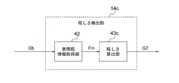
- the facial muscle information acquisition unit 42 detects the feature amount Fm of the facial muscle from the image of the driver's face, acquires information indicating the detected feature amount Fm (facial muscle information), and outputs the information (facial muscle information).
- the glare calculation unit 43 includes a pupil diameter Dp represented by pupil diameter information output from the pupil diameter information acquisition unit 41 and a feature amount Fm represented by facial muscle information output from the facial muscle information acquisition unit 42. From, the glare for the driver is calculated.
- the pupil diameter information acquisition unit 41 measures the pupil diameter Dp from the eye region of the image of the driver's face, and outputs the measurement result to the glare calculation unit 43.
- the facial muscle information acquisition unit 42 detects the feature amount Fm of the facial muscle from the image of the driver's face, and outputs the detection result to the glare calculation unit 43.
- the feature amount Fm of the facial muscles referred to here is an amount that increases due to a change in the state of the facial muscles when squinting due to glare, and may be an amount that represents the state of the facial muscles at each time point. It may be an amount calculated based on a change with the passage of time, for example, an amount obtained by integrating the amount of the above change.
- the glare calculation unit 43 calculates the glare level from the pupil diameter Dp and the feature amount Fm of the facial muscles, and outputs the information (glare information) GZ indicating the calculated glare level. For example, it is determined that the smaller the pupil diameter Dp, the greater the degree of glare, and the larger the pupil diameter Dp, the smaller the degree of glare. Further, it is determined that the larger the feature amount Fm of the facial muscle, the greater the degree of glare. The glare calculation unit 43 integrates these determination results to determine glare. For example, it is determined whether the glare level is "high”, “medium”, or "low” according to the magnitude of the glare.
- the glare level was set to 3 levels of "high”, “medium”, and “low", but the number of levels may be 2 or more than 3. For example, it may be about 10 steps.
- the brightness control unit 15 determines the brightness level of the display image in the image display unit 2 based on the line-of-sight determination information LS output from the line-of-sight detection unit 13 and the glare information GZ output from the glare detection unit 14. To do.
- the brightness level of the displayed image is determined in consideration of factors other than the line-of-sight determination information LS and the glare information GZ (hereinafter, referred to as “other factors” and indicated by reference numerals FC). For example, it is determined based on a signal indicating the brightness setting by the user and a signal based on the brightness of the image input to the image display unit 2.
- the determination of the luminance level based on the line-of-sight determination information LS and the glare information is performed as an adjustment or change with respect to the luminance level determined based on the other factor FC.
- the brightness level is determined, for example, by determining the emission brightness of the backlight 22.
- the brightness of each pixel of the display image is determined by the emission brightness of the backlight 22 and the value (pixel value) of the signal used to drive each pixel of the display panel 21.
- the brightness level of the displayed image is adjusted as follows.
- the luminance control unit 15 determines at each time point whether the driver is looking at the image display unit 2 or the outside of the image display unit 2 based on the line-of-sight determination information LS.
- the brightness control unit 15 stores a glare level when looking at the image display unit 2 and a glare level when looking at the outside of the image display unit 2 in an internal memory (not shown).
- the stored glare level is updated when new data representing the glare level is acquired. Data acquisition is performed every processing cycle.
- the glare level detected when it is determined that "the driver is looking at the image display unit 2" is stored as “the glare level when the driver is looking at the image display unit 2".
- the glare level detected when it is determined that "the driver is looking at the outside of the image display unit 2" is stored as "the glare level when looking at the outside of the image display unit 2". Will be done.
- the luminance control unit 15 determines whether the driver is looking at the image display unit 2 or the outside of the image display unit 2, and the glare level when the driver is looking at the image display unit 2. From the glare level when looking at the outside of the image display unit 2, it is determined whether or not it is necessary to adjust the brightness level, and if so, how to make the adjustment.
- the "glare level when looking at the image display unit 2" is the level of glare detected by the glare detection unit 14 at the present time.
- the "glare level when looking at the outside of the image display unit 2” means “looking at the outside of the image display unit 2" before the present time, which is stored in the brightness control unit 15. It means "the level of glare of time”.
- the "glare level when looking at the outside of the image display unit 2" is the glare detected by the glare detection unit 14 at the present time.
- the "glare level when looking at the image display unit 2” means the level of "glare when looking at the image display unit 2" before the present time, which is stored in the brightness control unit 15. It means "the level of the image”.
- the degree of adjustment means the width of adjustment or the coefficient used for adjustment.
- the adjustment width is added or subtracted with respect to the brightness level determined by the other factor FC.
- the adjustment range is added, and when the brightness level is decreased, the adjustment range is subtracted.
- the width of adjustment when raising and the width of adjustment when lowering may be different from each other.
- the adjustment factor is multiplied by the brightness level determined by the other factor FC. A coefficient greater than 1 is used to increase the luminance level, and a coefficient less than 1 is used to decrease the luminance level.
- the degree of adjustment is constant and predetermined, and in the determination regarding the adjustment of the luminance level, it is determined whether the luminance level should be increased, decreased, or maintained. Will be done.
- the decision regarding the adjustment of the brightness level is made according to, for example, a set of rules shown in FIG.
- the rules included in the set of rules shown in FIG. 5 are as follows.
- the brightness control unit 15 adjusts the brightness level according to the set of the above rules, and outputs a brightness control signal BA indicating the adjusted brightness level.
- the image display unit 2 controls the brightness of the backlight 22 according to the brightness control signal BA from the brightness control unit 15. Since the brightness level indicated by the brightness control signal BA is adjusted based on both the glare of the image display unit 2 and the glare of the external light, the display image in the image display unit 2 is the image display unit 2. The visibility is high regardless of the glare of the image and the glare of the outside light.
- FIG. 6 shows a set of rules for adjusting the brightness level in the comparative example.
- the luminance level is lowered when the glare level is “high”, and the luminance level is set when the glare level is “medium”. Maintain and increase the brightness level when the glare level is "low”.
- the driver may be strongly affected by the outside light.
- the illuminance is very high in the daytime on a sunny day in summer, and even when looking at the image display unit 2, a lot of outside light enters the driver's eyes.
- a large amount of outside light may enter the driver's eyes even when looking at the image display unit 2, such as reflected light from a vehicle in front, a high beam of an oncoming vehicle at night, or a sunset in the evening.
- the visibility of the image display unit 2 is lowered due to the influence of external light.
- the glare level when looking at the image display unit 2 is “high”, so that the brightness level is lowered, and as a result, the visibility is further lowered.
- the glare detection unit 14 in FIG. 3 includes a pupil diameter information acquisition unit 41 and a facial muscle information acquisition unit 42
- a glare detection unit including only one of these may be used. That is, as shown in FIG. 7, a glare detection unit 14b including a pupil diameter information acquisition unit 41 and a glare calculation unit 43b may be used, and as shown in FIG. 8, the facial muscle information acquisition unit 42 and the glare calculation A glare detection unit 14c including a unit 43c may be used.
- the glare calculation unit 43b of FIG. 7 determines the glare based on the pupil diameter Dp output from the pupil diameter information acquisition unit 41.
- the glare calculation unit 43c of FIG. 8 determines the glare based on the feature amount Fm output from the facial muscle information acquisition unit 42.
- the glare detection unit may detect glare based on at least one of the measurement result of the pupil diameter and the detection result of the feature amount of the facial muscle.
- the display control device 5 of FIG. 1 may be partially or wholly composed of a processing circuit.
- the functions of each part of the display control device 5 may be realized by separate processing circuits, or the functions of a plurality of parts may be collectively realized by one processing circuit.
- the processing circuit may be composed of hardware or software, that is, a programmed computer. Of the functions of each part of the display control device 5, a part may be realized by hardware and the other part may be realized by software.
- FIG. 9 shows a computer 9 that realizes all the functions of the display control device 5, together with an image display unit 2, a peripheral image pickup unit 3, and a driver image pickup unit 4.
- the computer 9 has a processor 91 and a memory 92.
- the memory 92 stores a program for realizing the functions of each part of the display control device 5.
- the processor 91 uses, for example, a CPU (Central Processing Unit), a GPU (Graphics Processing Unit), a microprocessor, a microcontroller, a DSP (Digital Signal Processor), or the like.
- a CPU Central Processing Unit
- GPU Graphics Processing Unit
- microprocessor a microcontroller
- DSP Digital Signal Processor
- the memory 92 includes, for example, a RAM (Random Access Memory), a ROM (Read Only Memory), a flash memory, an EPROM (Erasable Programmable Lead Only Memory), an EEPROM (Electrically Memory Memory, etc.) Alternatively, a photomagnetic disk or the like is used.
- the processor 91 realizes the function of the display control device 5 by executing the program stored in the memory 92.
- the function of the display control device 5 includes control of the display in the image display unit 2 (supply of a signal to the display panel 21 and control of the emission brightness of the backlight 22).
- the computer of FIG. 9 includes a single processor, but may include two or more processors.
- step ST1 the peripheral image Eb is acquired and output. This process is the same as the process in the peripheral image acquisition unit 11 of FIG.
- the output peripheral image Eb is supplied to the image display unit 2 and displayed by the image display unit 2.
- step ST3 the driver image is acquired and output.
- step ST4 line-of-sight detection is performed.
- step ST5 glare detection is performed.
- step ST6 the brightness is controlled.
- This process is the same as the process in the luminance control unit 15 of FIG.
- steps ST1 and steps ST3 to ST6 may be executed in different processing cycles.
- the brightness level of the displayed image can be appropriately controlled even when the driver's eyes are dazzled by external light, and the visibility of the displayed image is improved.
- FIG. 11 is a diagram showing a configuration of an image display device according to a second embodiment of the present invention.
- the image display device according to the second embodiment is generally the same as the image display device according to the first embodiment shown in FIG. However, an illuminance detection unit 6 is added, and a display control device 5b is provided instead of the display control device 5.
- the display control device 5b is generally the same as the display control device 5 of FIG. 1, but an illuminance acquisition unit 16 and a limit value determination unit 17 are added, and the brightness control unit 15b is added instead of the brightness control unit 15 of FIG. To be equipped.
- the illuminance detection unit 6 detects the illuminance around the image display unit 2 in the own vehicle or around the driver, and outputs the detection signal La.
- the illuminance detection unit 6 may be provided in the same housing as the image display unit 2. In the following, it is assumed that the illuminance around the driver is detected.
- the illuminance acquisition unit 16 receives the detection signal La from the illuminance detection unit 6 and acquires and outputs data (illuminance data) Lb indicating the illuminance.
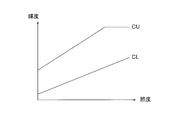
- the limit value determination unit 17 determines the upper limit value CU and the lower limit value CL based on the illuminance data Lb output from the illuminance acquisition unit 16.
- FIG. 12 is a diagram showing an example of an upper limit value CU and a lower limit value CL determined by the limit value determination unit 17.
- the limit value determination unit 17 stores in advance a table (limit value table) showing the relationship between the illuminance and the upper limit value and the lower limit value in an internal memory (not shown), and from the input illuminance, the upper limit value CU and the lower limit value CL. Is determined and output to the brightness control unit 15b.
- the limit value table may have an upper limit value CU and a lower limit value CL for each of the values that the detected illuminance can take, but is not limited to this. That is, for the illuminance having the upper limit value and the lower limit value discretely with respect to the illuminance value and not having the upper limit value and the lower limit value, the corresponding upper limit value and the lower limit value may be obtained by interpolation. This interpolation can be performed, for example, by using the upper limit value and the lower limit value corresponding to the illuminance value (table point) having the upper limit value and the lower limit value.
- the luminance control unit 15b receives the line-of-sight determination information LS output from the line-of-sight detection unit 13, the glare information GZ output from the glare detection unit 14, the other factor FC described above, and the limit value determination unit 17.
- the brightness level of the display image in the image display unit 2 is determined based on the upper limit value CU and the lower limit value CL. Specifically, the emission brightness of the backlight is determined.
- the determination of the luminance level based on the line-of-sight determination information LS, the glare information GZ, and the other factor FC is performed in the same manner as described in the first embodiment.
- the brightness control unit 15b sets the upper limit CU when the brightness level determined based on the line-of-sight determination information LS, the glare information GZ, and other factor FC, that is, the emission brightness of the backlight 22 exceeds the upper limit CU. Do not exceed the lower limit CL, and if it falls below the lower limit CL, do not fall below the lower limit CL. This process is performed, for example, by clipping. That is, the value above the upper limit CU is changed to match the upper limit CU, and the value below the lower limit CL is changed to match the lower limit CL.
- the display control device 5b of FIG. 11 may be partially or wholly composed of a processing circuit.
- the processing circuit may be configured by, for example, a computer similar to that shown in FIG.
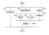
- the procedure of processing by the processor 91 when the display control device 5b described above is configured by a similar computer will be described with reference to FIG.
- the processing procedure shown in FIG. 13 is generally the same as the processing procedure shown in FIG. However, steps ST11 and ST12 are added, and step ST6 is replaced with step ST6b.
- step ST11 data indicating the illuminance is acquired and output.
- step ST12 the upper limit value CU and the lower limit value CL are determined.
- step ST6b the brightness is controlled. This process is the same as the process in the luminance control unit 15b of FIG.
- the luminance control unit 15b determines the upper limit value CU and the lower limit value CL according to the illuminance, and controls so that the luminance level of the displayed image does not exceed the upper limit value CU and does not fall below the lower limit value CL. It is possible to prevent the brightness of the displayed image from becoming excessively high or low.
- both the upper limit value CU and the lower limit value CL are used, but only one of the upper limit value CU and the lower limit value CL may be used. That is, the limit value determination unit 17 determines only one of the upper limit value CU and the lower limit value CL, and the brightness control unit does not exceed the upper limit value CU or the lower limit value CL so that the brightness level of the displayed image does not exceed the upper limit value CU.
- the control may be performed by 15b.
- FIG. 14 is a diagram showing a configuration of an image display device according to a third embodiment of the present invention.
- the image display device according to the third embodiment is generally the same as the image display device according to the first embodiment shown in FIG.
- the peripheral imaging unit 3 of FIG. 1 is not provided, an image supply source 7 is provided instead, and a display control device 5c is provided instead of the display control device 5.
- the display control device 5c is generally the same as the display control device 5 of FIG. 1, but is not provided with the peripheral image acquisition unit 11, but is provided with an image receiving unit 18 instead.
- the image supply source 7 supplies an image Ga other than the peripheral image.
- the image other than the peripheral image is, for example, a car navigation image, an image representing an instrument, or the like.
- the instrument referred to here is, for example, an instrument included in the instrument panel of a vehicle, for example, a speedometer, a fuel gauge, or the like.
- the image receiving unit 18 receives the image Ga supplied from the image supply source 7, converts it into a form suitable for display on the image display unit 2, and outputs the image Gb obtained by the conversion.
- the image display unit 2 displays the image Gb output from the image receiving unit 18 on the display panel 21.
- the image display unit 2 also controls the brightness of the backlight 22 according to the brightness control signal BA output from the brightness control unit 15. Therefore, the visibility of the displayed image can be improved according to both the glare of the image display unit 2 and the glare of the outside light for the driver.
- the display control device 5c of FIG. 14 may be partially or wholly composed of a processing circuit.
- the processing circuit may be configured by, for example, a computer similar to that shown in FIG.
- the procedure of processing by the processor 91 when the display control device 5c described above is configured by a similar computer will be described with reference to FIG.
- step ST1 of FIG. 10 is not provided, and step ST21 is provided instead.
- step ST21 the image Ga is received and converted, and the converted image Gb is output. This process is the same as the process in the image receiving unit 18 of FIG.
- the same effect as that of the first embodiment can be obtained even when an image other than the peripheral image is displayed on the image display unit 2.
- Embodiment 4 the image display unit 2 shown in FIG. 2 is used.
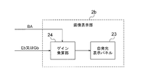
- the image display unit 2b shown in FIG. 16 may be used.
- the image display unit 2b shown in FIG. 16 includes a self-luminous display panel 23 and a gain multiplication unit 24.
- the self-luminous display panel 23 is composed of, for example, an organic EL (Electroluminescence) panel.
- the gain multiplication unit 24 determines the gain according to the luminance control signal BA, and multiplies the determined gain by the image data representing the image Eb or Gb. A larger gain is used when increasing the luminance level, and a smaller gain is used when decreasing the luminance level.
- the self-luminous display panel 23 displays an image based on the image data obtained as a result of the multiplication in the gain multiplication unit 24.
- the image display unit 2b controls the brightness level of the displayed image by determining the gain according to the brightness control signal BA. Also in the fourth embodiment, the same effects as those of the first to third embodiments can be obtained.
- Embodiment 5 The following modifications can be made to the set of rules regarding the adjustment of the brightness level in the brightness control unit 15 or 15b.
- the set of rules shown in FIG. 17 can be used instead of the set of rules described with reference to FIG.
- the set of rules shown in FIG. 17 is generally the same as the set of rules shown in FIG. However, instead of the above rules (a11) to (a13), the following rule (a1) is used.
- the process of maximizing the brightness level of the displayed image is performed by maximizing the emission brightness of the backlight 22.
- the above "maximum” means the upper limit value CU. This is because clipping is performed.
- the process of maximizing the brightness level of the display image is the image obtained as a result of the multiplication by the gain multiplication unit 24.
- the maximum gradation value of the data should be the maximum value within the range of values that can be accepted by the display panel.
- the rule (a1) is applied to the configuration obtained by adding the modification of the fourth embodiment to the second embodiment, the above "maximum value" means the upper limit value CU. This is because clipping is performed.
- the glare level when looking at the outside of the image display unit 2 is “high”, the glare when looking at the image display unit 2 Since the brightness of the image display unit 2 is maximized regardless of the level, the visibility of the displayed image can be improved even when the driver feels that the outside light is dazzling.
- Embodiment 6 instead of the set of rules described with reference to FIG. 5, the set of rules shown in FIG. 18 can also be used.
- the set of rules shown in FIG. 18 is generally the same as the set of rules shown in FIG. However, instead of the above rule (a11), the following rule (a11b) is used. (A11b) When the glare level when looking at the outside of the image display unit 2 is "high” and the glare level when looking at the image display unit 2 is "high”, the brightness level of the displayed image is lowered. Let me.
- the sixth embodiment assumes that the light received by the driver from the image display unit is stronger than the light received from the outside light.
- the glare level when looking at the outside of the image display unit 2 is "high” according to the above rule (a11b), and the image display unit.
- the glare level when looking at 2 is "high”
- the brightness level of the displayed image is lowered, so that the glare of the image display unit 2 can be reduced and the visibility of the displayed image is improved.
- the image display device includes one image display unit.
- two or more display control devices corresponding to the image display units may be provided, and each display control device may control the display in the corresponding image display unit. ..
- at least a part of the peripheral image pickup unit 3, the driver image pickup section 4, the illuminance detection section 6, and the image supply source 7 may be shared.
- a part of two or more display control devices may be shared.
- a portion of the driver image acquisition unit 12, the glare detection unit 14, and the line-of-sight detection unit 13 that detects the line of sight may be shared.
- a single display control device having the above-mentioned common portion and a portion provided corresponding to each image display unit may be configured.
- the display control device constituting the image display device, the image display method implemented by the image display device, and the display control method implemented by the display control device are also a part of the present invention.
- a program that causes a computer to execute a process in the above-mentioned display control device or display control method, and a computer-readable recording medium that records the program, for example, a non-temporary recording medium, also form a part of the present invention.
- 2,2b image display unit 3 peripheral image acquisition unit, 4 driver imaging unit, 5,5b, 5c display control device, 6 illuminance detection unit, 7 image supply source, 11 peripheral image acquisition unit, 12 driver image acquisition unit, 13 line-of-sight detection unit, 14, 14b, 14c glare detection unit, 15, 15b brightness control unit, 16 illuminance acquisition unit, 17 limit value determination unit, 18 image reception unit, 21 display panel, 22 backlight, 23 self-luminous display Panel, 24 gain multiplication unit, 41 pupil diameter information acquisition unit, 42 facial muscle information acquisition unit, 43, 43b, 43c glare calculation unit.
Landscapes
- Engineering & Computer Science (AREA)
- Chemical & Material Sciences (AREA)
- Combustion & Propulsion (AREA)
- Transportation (AREA)
- Mechanical Engineering (AREA)
- Theoretical Computer Science (AREA)
- Physics & Mathematics (AREA)
- General Physics & Mathematics (AREA)
- Human Computer Interaction (AREA)
- Computer Hardware Design (AREA)
- General Engineering & Computer Science (AREA)
- Multimedia (AREA)
- Crystallography & Structural Chemistry (AREA)
- Ophthalmology & Optometry (AREA)
- General Health & Medical Sciences (AREA)
- Health & Medical Sciences (AREA)
- Computer Vision & Pattern Recognition (AREA)
- Controls And Circuits For Display Device (AREA)
- Instrument Panels (AREA)
- Two-Way Televisions, Distribution Of Moving Picture Or The Like (AREA)
- Image Analysis (AREA)
Priority Applications (5)
| Application Number | Priority Date | Filing Date | Title |
|---|---|---|---|
| CN201980100296.5A CN114450185B (zh) | 2019-09-30 | 2019-09-30 | 图像显示装置、显示控制装置、显示控制方法以及记录介质 |
| DE112019007765.1T DE112019007765T5 (de) | 2019-09-30 | 2019-09-30 | Bildanzeigeeinrichtung, Anzeigesteuerungseinrichtung, und Anzeigesteuerungsverfahren, und Programm und Aufzeichnungsmedium |
| US17/633,587 US11675431B2 (en) | 2019-09-30 | 2019-09-30 | Image display device, display control device, and display control method, and program and recording medium |
| JP2021550751A JP7199562B2 (ja) | 2019-09-30 | 2019-09-30 | 画像表示装置、表示制御装置、及び表示制御方法、並びにプログラム及び記録媒体 |
| PCT/JP2019/038511 WO2021064791A1 (ja) | 2019-09-30 | 2019-09-30 | 画像表示装置、表示制御装置、及び表示制御方法、並びにプログラム及び記録媒体 |
Applications Claiming Priority (1)
| Application Number | Priority Date | Filing Date | Title |
|---|---|---|---|
| PCT/JP2019/038511 WO2021064791A1 (ja) | 2019-09-30 | 2019-09-30 | 画像表示装置、表示制御装置、及び表示制御方法、並びにプログラム及び記録媒体 |
Publications (1)
| Publication Number | Publication Date |
|---|---|
| WO2021064791A1 true WO2021064791A1 (ja) | 2021-04-08 |
Family
ID=75337779
Family Applications (1)
| Application Number | Title | Priority Date | Filing Date |
|---|---|---|---|
| PCT/JP2019/038511 Ceased WO2021064791A1 (ja) | 2019-09-30 | 2019-09-30 | 画像表示装置、表示制御装置、及び表示制御方法、並びにプログラム及び記録媒体 |
Country Status (5)
| Country | Link |
|---|---|
| US (1) | US11675431B2 (https=) |
| JP (1) | JP7199562B2 (https=) |
| CN (1) | CN114450185B (https=) |
| DE (1) | DE112019007765T5 (https=) |
| WO (1) | WO2021064791A1 (https=) |
Cited By (1)
| Publication number | Priority date | Publication date | Assignee | Title |
|---|---|---|---|---|
| CN115269653A (zh) * | 2022-07-29 | 2022-11-01 | 中汽研汽车检验中心(武汉)有限公司 | 一种针对安全达标车型检测项目的自动视同判定方法 |
Families Citing this family (1)
| Publication number | Priority date | Publication date | Assignee | Title |
|---|---|---|---|---|
| CN116823929B (zh) * | 2023-05-23 | 2026-03-24 | 清华大学 | 基于视觉图像与点云地图的跨模态匹配定位方法及系统 |
Citations (5)
| Publication number | Priority date | Publication date | Assignee | Title |
|---|---|---|---|---|
| JP2007276766A (ja) * | 2006-03-15 | 2007-10-25 | Omron Corp | 監視装置および方法、記録媒体、並びに、プログラム |
| JP2011093413A (ja) * | 2009-10-29 | 2011-05-12 | Nippon Seiki Co Ltd | 車両用表示装置 |
| JP2013147187A (ja) * | 2012-01-20 | 2013-08-01 | Denso Corp | 防眩制御装置 |
| JP2018125707A (ja) * | 2017-02-01 | 2018-08-09 | ソニーセミコンダクタソリューションズ株式会社 | 表示制御装置および方法、並びにプログラム |
| JP2018185654A (ja) * | 2017-04-26 | 2018-11-22 | 日本精機株式会社 | ヘッドアップディスプレイ装置 |
Family Cites Families (11)
| Publication number | Priority date | Publication date | Assignee | Title |
|---|---|---|---|---|
| JP4481187B2 (ja) * | 2005-02-10 | 2010-06-16 | 本田技研工業株式会社 | 車両用操作装置 |
| CN101034524B (zh) * | 2006-03-10 | 2011-01-12 | 精工爱普生株式会社 | 显示方法、显示装置及电子机器 |
| JP2007245911A (ja) * | 2006-03-15 | 2007-09-27 | Omron Corp | 監視装置および方法、記録媒体、並びに、プログラム |
| JP4687573B2 (ja) | 2006-06-14 | 2011-05-25 | トヨタ自動車株式会社 | 車両用運転支援装置 |
| JP5208711B2 (ja) | 2008-12-17 | 2013-06-12 | アイシン精機株式会社 | 眼開閉判別装置及びプログラム |
| JP5802926B2 (ja) * | 2011-02-04 | 2015-11-04 | 富士重工業株式会社 | 車載表示装置の輝度制御装置、輝度制御プログラムおよび輝度制御方法 |
| JP5983693B2 (ja) * | 2014-09-10 | 2016-09-06 | 株式会社Jvcケンウッド | 表示機能付きミラー装置および表示切替方法 |
| KR20180027590A (ko) * | 2015-08-14 | 2018-03-14 | 젠텍스 코포레이션 | 헤드업 디스플레이 시스템 |
| JP6410987B2 (ja) * | 2016-02-25 | 2018-10-24 | 富士フイルム株式会社 | 運転支援装置、運転支援方法、及び、運転支援プログラム |
| JP6587254B2 (ja) | 2016-09-16 | 2019-10-09 | 株式会社東海理化電機製作所 | 輝度制御装置、輝度制御システム及び輝度制御方法 |
| KR20180060788A (ko) * | 2016-11-29 | 2018-06-07 | 삼성전자주식회사 | 눈부심 방지 장치 및 방법 |
-
2019
- 2019-09-30 DE DE112019007765.1T patent/DE112019007765T5/de active Pending
- 2019-09-30 CN CN201980100296.5A patent/CN114450185B/zh active Active
- 2019-09-30 US US17/633,587 patent/US11675431B2/en active Active
- 2019-09-30 JP JP2021550751A patent/JP7199562B2/ja active Active
- 2019-09-30 WO PCT/JP2019/038511 patent/WO2021064791A1/ja not_active Ceased
Patent Citations (5)
| Publication number | Priority date | Publication date | Assignee | Title |
|---|---|---|---|---|
| JP2007276766A (ja) * | 2006-03-15 | 2007-10-25 | Omron Corp | 監視装置および方法、記録媒体、並びに、プログラム |
| JP2011093413A (ja) * | 2009-10-29 | 2011-05-12 | Nippon Seiki Co Ltd | 車両用表示装置 |
| JP2013147187A (ja) * | 2012-01-20 | 2013-08-01 | Denso Corp | 防眩制御装置 |
| JP2018125707A (ja) * | 2017-02-01 | 2018-08-09 | ソニーセミコンダクタソリューションズ株式会社 | 表示制御装置および方法、並びにプログラム |
| JP2018185654A (ja) * | 2017-04-26 | 2018-11-22 | 日本精機株式会社 | ヘッドアップディスプレイ装置 |
Cited By (2)
| Publication number | Priority date | Publication date | Assignee | Title |
|---|---|---|---|---|
| CN115269653A (zh) * | 2022-07-29 | 2022-11-01 | 中汽研汽车检验中心(武汉)有限公司 | 一种针对安全达标车型检测项目的自动视同判定方法 |
| CN115269653B (zh) * | 2022-07-29 | 2023-07-04 | 中汽研汽车检验中心(武汉)有限公司 | 一种针对安全达标车型检测项目的自动视同判定方法 |
Also Published As
| Publication number | Publication date |
|---|---|
| CN114450185B (zh) | 2024-07-16 |
| US20220308663A1 (en) | 2022-09-29 |
| CN114450185A (zh) | 2022-05-06 |
| US11675431B2 (en) | 2023-06-13 |
| JPWO2021064791A1 (https=) | 2021-04-08 |
| DE112019007765T5 (de) | 2022-06-15 |
| JP7199562B2 (ja) | 2023-01-05 |
Similar Documents
| Publication | Publication Date | Title |
|---|---|---|
| US9041807B2 (en) | Image processing device and image processing method | |
| US9269330B2 (en) | Head mounted display apparatus and backlight adjustment method thereof | |
| CN109996052B (zh) | 一种车载显示装置、车载显示方法、存储介质及车辆 | |
| US10587819B2 (en) | Video display system, video display device, and video display method | |
| JP4812008B2 (ja) | 画像表示装置 | |
| JP5802926B2 (ja) | 車載表示装置の輝度制御装置、輝度制御プログラムおよび輝度制御方法 | |
| EP2748809A1 (en) | Display device control | |
| EP3559900A1 (en) | System and method for compensation of reflection on a display device | |
| JP6775442B2 (ja) | 車両に用いられる表示装置、車両に用いられる表示制御装置、及び車両に用いられる表示制御方法 | |
| JP6186465B2 (ja) | 注視追跡に基づく電子ディスプレイの調整 | |
| EP3240288A1 (en) | Image capturing system | |
| JP2012521726A (ja) | 熱画像から明るい画像を適応的に抽出する方法及びシステム | |
| JP7199562B2 (ja) | 画像表示装置、表示制御装置、及び表示制御方法、並びにプログラム及び記録媒体 | |
| JP7182368B2 (ja) | 車載表示装置、車載表示装置を制御する方法及びコンピュータプログラム | |
| TW202013007A (zh) | 近眼顯示系統及其顯示方法 | |
| JP2017112486A (ja) | 画像処理装置 | |
| CN120108310B (zh) | 一种显示屏的显示方法、装置和电子设备 | |
| JP2020003704A (ja) | 情報処理装置 | |
| JP2005219583A (ja) | 前方視界の視認性向上方法、及び車両用表示装置 | |
| JP4710403B2 (ja) | 車両用画像生成装置および方法 | |
| JP2014202941A (ja) | 表示装置、表示方法、およびプログラム | |
| JP7698998B2 (ja) | 画像表示システムおよび画像表示方法 | |
| WO2011155228A1 (ja) | 画像表示装置 | |
| JP2011181019A (ja) | 俯瞰画像生成装置 | |
| JP7635977B2 (ja) | 調光装置 |
Legal Events
| Date | Code | Title | Description |
|---|---|---|---|
| 121 | Ep: the epo has been informed by wipo that ep was designated in this application |
Ref document number: 19947705 Country of ref document: EP Kind code of ref document: A1 |
|
| ENP | Entry into the national phase |
Ref document number: 2021550751 Country of ref document: JP Kind code of ref document: A |
|
| 122 | Ep: pct application non-entry in european phase |
Ref document number: 19947705 Country of ref document: EP Kind code of ref document: A1 |