WO2021064791A1 - Image display device, display control device, display control method, program, and recording medium - Google Patents
Image display device, display control device, display control method, program, and recording medium Download PDFInfo
- Publication number
- WO2021064791A1 WO2021064791A1 PCT/JP2019/038511 JP2019038511W WO2021064791A1 WO 2021064791 A1 WO2021064791 A1 WO 2021064791A1 JP 2019038511 W JP2019038511 W JP 2019038511W WO 2021064791 A1 WO2021064791 A1 WO 2021064791A1
- Authority
- WO
- WIPO (PCT)
- Prior art keywords
- image
- image display
- display unit
- driver
- glare
- Prior art date
Links
- 238000000034 method Methods 0.000 title claims description 44
- 230000004313 glare Effects 0.000 claims abstract description 146
- 238000003384 imaging method Methods 0.000 claims abstract description 22
- 238000001514 detection method Methods 0.000 claims description 55
- 230000002093 peripheral effect Effects 0.000 claims description 40
- 210000001747 pupil Anatomy 0.000 claims description 28
- 210000001097 facial muscle Anatomy 0.000 claims description 21
- 238000005259 measurement Methods 0.000 claims description 4
- 238000012545 processing Methods 0.000 description 25
- 238000010586 diagram Methods 0.000 description 14
- 230000006870 function Effects 0.000 description 8
- 238000012986 modification Methods 0.000 description 6
- 230000004048 modification Effects 0.000 description 6
- 230000000052 comparative effect Effects 0.000 description 4
- 230000003247 decreasing effect Effects 0.000 description 3
- 230000000694 effects Effects 0.000 description 3
- 239000002131 composite material Substances 0.000 description 2
- 101001139126 Homo sapiens Krueppel-like factor 6 Proteins 0.000 description 1
- 208000004350 Strabismus Diseases 0.000 description 1
- 238000006243 chemical reaction Methods 0.000 description 1
- 230000008602 contraction Effects 0.000 description 1
- 238000005401 electroluminescence Methods 0.000 description 1
- 239000000446 fuel Substances 0.000 description 1
- 239000004973 liquid crystal related substance Substances 0.000 description 1
- 238000012544 monitoring process Methods 0.000 description 1
- 210000001525 retina Anatomy 0.000 description 1
Images


Classifications
-
- G—PHYSICS
- G06—COMPUTING; CALCULATING OR COUNTING
- G06F—ELECTRIC DIGITAL DATA PROCESSING
- G06F3/00—Input arrangements for transferring data to be processed into a form capable of being handled by the computer; Output arrangements for transferring data from processing unit to output unit, e.g. interface arrangements
- G06F3/01—Input arrangements or combined input and output arrangements for interaction between user and computer
- G06F3/011—Arrangements for interaction with the human body, e.g. for user immersion in virtual reality
- G06F3/013—Eye tracking input arrangements
-
- B—PERFORMING OPERATIONS; TRANSPORTING
- B60—VEHICLES IN GENERAL
- B60K—ARRANGEMENT OR MOUNTING OF PROPULSION UNITS OR OF TRANSMISSIONS IN VEHICLES; ARRANGEMENT OR MOUNTING OF PLURAL DIVERSE PRIME-MOVERS IN VEHICLES; AUXILIARY DRIVES FOR VEHICLES; INSTRUMENTATION OR DASHBOARDS FOR VEHICLES; ARRANGEMENTS IN CONNECTION WITH COOLING, AIR INTAKE, GAS EXHAUST OR FUEL SUPPLY OF PROPULSION UNITS IN VEHICLES
- B60K35/00—Arrangement of adaptations of instruments
-
- B60K35/10—
-
- B60K35/22—
-
- G—PHYSICS
- G06—COMPUTING; CALCULATING OR COUNTING
- G06V—IMAGE OR VIDEO RECOGNITION OR UNDERSTANDING
- G06V20/00—Scenes; Scene-specific elements
- G06V20/50—Context or environment of the image
- G06V20/59—Context or environment of the image inside of a vehicle, e.g. relating to seat occupancy, driver state or inner lighting conditions
- G06V20/597—Recognising the driver's state or behaviour, e.g. attention or drowsiness
-
- G—PHYSICS
- G06—COMPUTING; CALCULATING OR COUNTING
- G06V—IMAGE OR VIDEO RECOGNITION OR UNDERSTANDING
- G06V40/00—Recognition of biometric, human-related or animal-related patterns in image or video data
- G06V40/10—Human or animal bodies, e.g. vehicle occupants or pedestrians; Body parts, e.g. hands
- G06V40/18—Eye characteristics, e.g. of the iris
- G06V40/193—Preprocessing; Feature extraction
-
- G—PHYSICS
- G09—EDUCATION; CRYPTOGRAPHY; DISPLAY; ADVERTISING; SEALS
- G09G—ARRANGEMENTS OR CIRCUITS FOR CONTROL OF INDICATING DEVICES USING STATIC MEANS TO PRESENT VARIABLE INFORMATION
- G09G3/00—Control arrangements or circuits, of interest only in connection with visual indicators other than cathode-ray tubes
- G09G3/20—Control arrangements or circuits, of interest only in connection with visual indicators other than cathode-ray tubes for presentation of an assembly of a number of characters, e.g. a page, by composing the assembly by combination of individual elements arranged in a matrix no fixed position being assigned to or needed to be assigned to the individual characters or partial characters
- G09G3/34—Control arrangements or circuits, of interest only in connection with visual indicators other than cathode-ray tubes for presentation of an assembly of a number of characters, e.g. a page, by composing the assembly by combination of individual elements arranged in a matrix no fixed position being assigned to or needed to be assigned to the individual characters or partial characters by control of light from an independent source
- G09G3/3406—Control of illumination source
-
- G—PHYSICS
- G09—EDUCATION; CRYPTOGRAPHY; DISPLAY; ADVERTISING; SEALS
- G09G—ARRANGEMENTS OR CIRCUITS FOR CONTROL OF INDICATING DEVICES USING STATIC MEANS TO PRESENT VARIABLE INFORMATION
- G09G3/00—Control arrangements or circuits, of interest only in connection with visual indicators other than cathode-ray tubes
- G09G3/20—Control arrangements or circuits, of interest only in connection with visual indicators other than cathode-ray tubes for presentation of an assembly of a number of characters, e.g. a page, by composing the assembly by combination of individual elements arranged in a matrix no fixed position being assigned to or needed to be assigned to the individual characters or partial characters
- G09G3/34—Control arrangements or circuits, of interest only in connection with visual indicators other than cathode-ray tubes for presentation of an assembly of a number of characters, e.g. a page, by composing the assembly by combination of individual elements arranged in a matrix no fixed position being assigned to or needed to be assigned to the individual characters or partial characters by control of light from an independent source
- G09G3/36—Control arrangements or circuits, of interest only in connection with visual indicators other than cathode-ray tubes for presentation of an assembly of a number of characters, e.g. a page, by composing the assembly by combination of individual elements arranged in a matrix no fixed position being assigned to or needed to be assigned to the individual characters or partial characters by control of light from an independent source using liquid crystals
-
- B60K2360/149—
-
- B60K2360/349—
-
- G—PHYSICS
- G09—EDUCATION; CRYPTOGRAPHY; DISPLAY; ADVERTISING; SEALS
- G09G—ARRANGEMENTS OR CIRCUITS FOR CONTROL OF INDICATING DEVICES USING STATIC MEANS TO PRESENT VARIABLE INFORMATION
- G09G2354/00—Aspects of interface with display user
-
- G—PHYSICS
- G09—EDUCATION; CRYPTOGRAPHY; DISPLAY; ADVERTISING; SEALS
- G09G—ARRANGEMENTS OR CIRCUITS FOR CONTROL OF INDICATING DEVICES USING STATIC MEANS TO PRESENT VARIABLE INFORMATION
- G09G2360/00—Aspects of the architecture of display systems
- G09G2360/14—Detecting light within display terminals, e.g. using a single or a plurality of photosensors
- G09G2360/144—Detecting light within display terminals, e.g. using a single or a plurality of photosensors the light being ambient light
-
- G—PHYSICS
- G09—EDUCATION; CRYPTOGRAPHY; DISPLAY; ADVERTISING; SEALS
- G09G—ARRANGEMENTS OR CIRCUITS FOR CONTROL OF INDICATING DEVICES USING STATIC MEANS TO PRESENT VARIABLE INFORMATION
- G09G2360/00—Aspects of the architecture of display systems
- G09G2360/14—Detecting light within display terminals, e.g. using a single or a plurality of photosensors
- G09G2360/145—Detecting light within display terminals, e.g. using a single or a plurality of photosensors the light originating from the display screen
-
- G—PHYSICS
- G09—EDUCATION; CRYPTOGRAPHY; DISPLAY; ADVERTISING; SEALS
- G09G—ARRANGEMENTS OR CIRCUITS FOR CONTROL OF INDICATING DEVICES USING STATIC MEANS TO PRESENT VARIABLE INFORMATION
- G09G2380/00—Specific applications
- G09G2380/10—Automotive applications
Definitions
- the present invention relates to an image display device, a display control device, and a display control method.
- the present invention particularly relates to improving the visibility of an image displayed on an image display unit mounted in a vehicle.
- the present invention also relates to programs and recording media.
- an electronic mirror device has been proposed as an alternative to a physical mirror used as a rearview mirror and a side mirror.
- the electronic mirror device displays an image obtained by imaging with a camera directed to the rear of the vehicle or the like on a display device.
- the pupil diameter of the driver is acquired from the image of the driver obtained by the driver monitoring system (DMS), and is displayed based on the difference between the acquired pupil diameter and the diameter stored in advance.
- DMS driver monitoring system
- a technique for controlling brightness has been proposed.
- the brightness of the display may not be properly controlled.
- the driver when the driver is looking at the display screen in the vehicle in an environment with high illuminance such as daytime, the driver's eyes may get outside light and feel dazzling.
- the lights of an oncoming vehicle may get into the driver's eyes and feel dazzling.
- the brightness of the display is lowered according to the teaching of Patent Document 1, the visibility of the displayed image is lowered.
- An object of the present invention is to improve the visibility of the displayed image even when the driver feels dazzling due to external light entering the eyes.
- the image display device of the present invention An image display unit that is installed in the vehicle and displays images, A driver imaging unit that captures the driver of the vehicle, The image of the driver is acquired from the image obtained by the image captured by the driver imaging unit, the line of sight of the driver is detected from the image of the driver, and the detected line of sight and the image display unit are used. It is determined from the information indicating the position whether the driver is looking at the image display unit or the outside of the image display unit, and the glare felt by the driver from the image of the driver. Is provided, and a display control device for determining the brightness level of the display image in the image display unit from the glare when looking at the image display unit and the glare when looking at the outside of the image display unit is provided. , The image display unit displays an image at a brightness level determined by the display control device.
- the display control device of the present invention In a display control device that is mounted in a vehicle and adjusts the brightness of a display image in an image display unit that displays an image.
- the driver's line of sight is detected from the driver's image obtained by imaging, and the driver is looking at the image display unit from the detected line of sight and information indicating the position of the image display unit.
- a line-of-sight detection unit that determines whether you are looking outside the image display unit
- a glare detection unit that detects the glare felt by the driver from the driver's image
- It is provided with a brightness control unit that determines the brightness level of the displayed image in the image display unit from the glare when looking at the image display unit and the glare when looking at the outside of the image display unit.
- the image display unit displays an image at a brightness level determined by the brightness control unit.
- the visibility of the displayed image can be improved even when the driver feels dazzling due to external light entering the eyes.
- FIG. 5 is a flowchart showing a processing procedure by a processor when the display control device of FIG. 11 is composed of a computer.
- FIG. 5 is a flowchart showing a processing procedure by a processor when the display control device of FIG. 14 is composed of a computer. It is a block diagram which shows the structural example of the image display part used in Embodiment 4 of this invention. It is a table which shows the example of the set of the rule of brightness level adjustment applied in Embodiment 5 of this invention. It is a table which shows the example of the set of the rule of brightness level adjustment applied in Embodiment 6 of this invention.
- FIG. 1 is a diagram showing a configuration of an image display device according to a first embodiment of the present invention.
- the illustrated image display device includes an image display unit 2, a peripheral image pickup unit 3, a driver image pickup section 4, and a display control device 5.
- the image display unit 2 is mounted in the vehicle and is arranged at a position suitable for the driver to see the display screen.
- the driver is the person sitting in the driver's seat.
- the vehicle on which the image display unit 2 is mounted may be referred to as a own vehicle.
- the image display unit 2 has a display panel 21 and a backlight 22, as shown in FIG. 2, for example.
- the display panel 21 is composed of, for example, a transmissive display panel, for example, a transmissive LCD (Liquid Crystal Display) panel.
- the backlight 22 is provided on the back side of the display panel 21.
- the peripheral imaging unit 3 includes, for example, one or more cameras, images the periphery of the own vehicle, and outputs the image Ea obtained by the imaging.
- the driver imaging unit 4 includes, for example, one or more cameras, images the driver, and outputs the image Da obtained by the imaging.
- the display control device 5 receives the image Ea output from the peripheral imaging unit 3, and causes the image display unit 2 to display the image or an image obtained by processing the image Ea.
- the display control device 5 detects the glare felt by the driver based on the image Da output from the driver imaging unit 4, and whether the driver is looking at the image display unit 2 or the image display unit 2 It is determined whether or not the image is viewed from the outside, the brightness level is determined based on the result of the above detection and the result of the above determination, and the brightness level of the image displayed by the image display unit 2 is controlled.
- the display control device 5 includes a peripheral image acquisition unit 11, a driver image acquisition unit 12, a line-of-sight detection unit 13, a glare detection unit 14, and a brightness control unit 15.
- the peripheral image acquisition unit 11 receives the image Ea output from the peripheral image pickup unit 3, acquires an image (peripheral image) Eb showing the situation around the own vehicle, and outputs the image Eb.
- the peripheral image acquisition unit 11 may output the image obtained by imaging with the camera as it is as the peripheral image Eb, and the peripheral image acquisition unit 11 may output the image obtained by the camera as it is. A part of the obtained image may be cut out and output as a peripheral image Eb.
- the peripheral image acquisition unit 11 selects an image obtained by imaging with one of the two or more cameras, and uses the selected image as the peripheral image Eb as it is. It may be output, or a part of the selected image may be cut out and output as a peripheral image Eb. Further, the peripheral image acquisition unit 11 may generate a composite image based on the images obtained by imaging with two or more cameras, and output the generated composite image as the peripheral image Eb.
- the peripheral image acquisition unit 11 may output an image of the own vehicle in a fixed direction as a peripheral image Eb.
- an image in a different direction may be output as a peripheral image Eb according to the driving situation of the own vehicle. For example, when making a right turn, making a left turn, changing lanes, moving backward, etc., an image in a direction with a high degree of necessity for driving may be output as a peripheral image Eb.
- the image display unit 2 displays the peripheral image Eb output from the peripheral image acquisition unit 11 on the display panel 21.
- the driver image acquisition unit 12 receives the image Da output from the driver image pickup unit 4, acquires the driver image (driver image) Db, and outputs the image Da.
- the driver image Db is an image including the driver's face.
- the driver image acquisition unit 12 may output the image obtained by the image pickup by the camera as it is as the driver image Db, and the camera may output the image.
- a part of the image obtained by the imaging of the above may be cut out and output as a driver image Db.
- the image obtained by capturing with a camera includes not only the driver but also the surroundings of the driver, and the image obtained by cutting out a part of such an image is used as the driver image Db. You may output it.
- the driver image acquisition unit 12 selects an image obtained by imaging with one of the two or more cameras, and the selected image is used as it is by the driver. It may be output as an image Db, or a part of the selected image may be cut out and output as a driver image Db. Further, two or more images obtained by photographing the driver from different directions using two or more cameras may be output as a driver image Db, and such two or more images may be combined. The image obtained by the above may be output as the driver image Db.
- the line-of-sight detection unit 13 detects the line of sight from the driver image Db output from the driver image acquisition unit 12.
- Line-of-sight detection includes detection of the position of the viewpoint and detection of the direction of the line of sight.
- the line-of-sight detection unit 13 may calculate the line-of-sight from the direction of the driver's face and the positions of the pupils of the driver's left and right eyes.
- the line-of-sight detection unit 13 further determines whether the driver is looking at the image display unit 2 from the result of the line-of-sight detection and the information PL indicating the position of the image display unit 2 stored in advance in an internal memory (not shown). , It is determined whether or not the outside of the image display unit 2 is being viewed, and information (line-of-sight determination information) LS indicating the determination result is output.
- the image display unit 2 In determining whether the image display unit 2 is being viewed or the outside of the image display unit 2 is being viewed, the image display unit 2 is limited to viewing a specific portion of the image display unit 2, for example, the central portion of the display screen. It may be determined that the image is being viewed, or it may be determined that the image display unit 2 is being viewed even when the user is looking at any point within a range slightly wider than the image display unit 2.
- determining that the image display unit 2 is looking outside only when the driver is looking in a specific direction outside the image display unit 2, for example, when the driver is looking ahead, " It may be determined that "the outside of the image display unit 2 is being viewed”. Further, if it does not correspond to "when looking at the image display unit 2", it may be determined that "looking at the outside of the image display unit 2". In the latter case, "when looking at the outside of the image display unit 2" includes a time when the viewpoint is not fixed and no one is looking at anything.
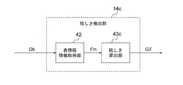
- the glare detection unit 14 detects the glare level felt by the driver from the driver image Db output from the driver image acquisition unit 12, and outputs information (glare information) GZ indicating the detected glare level. Output.
- the glare detection unit 14 includes, for example, a pupil diameter information acquisition unit 41, a facial muscle information acquisition unit 42, and a glare calculation unit 43.
- the pupil diameter information acquisition unit 41 measures the pupil diameter Dp, acquires information indicating the measured pupil diameter Dp (pupil diameter information), and outputs the information (pupil diameter information).
- the facial muscle information acquisition unit 42 detects the feature amount Fm of the facial muscle from the image of the driver's face, acquires information indicating the detected feature amount Fm (facial muscle information), and outputs the information (facial muscle information).
- the glare calculation unit 43 includes a pupil diameter Dp represented by pupil diameter information output from the pupil diameter information acquisition unit 41 and a feature amount Fm represented by facial muscle information output from the facial muscle information acquisition unit 42. From, the glare for the driver is calculated.
- the pupil diameter information acquisition unit 41 measures the pupil diameter Dp from the eye region of the image of the driver's face, and outputs the measurement result to the glare calculation unit 43.
- the facial muscle information acquisition unit 42 detects the feature amount Fm of the facial muscle from the image of the driver's face, and outputs the detection result to the glare calculation unit 43.
- the feature amount Fm of the facial muscles referred to here is an amount that increases due to a change in the state of the facial muscles when squinting due to glare, and may be an amount that represents the state of the facial muscles at each time point. It may be an amount calculated based on a change with the passage of time, for example, an amount obtained by integrating the amount of the above change.
- the glare calculation unit 43 calculates the glare level from the pupil diameter Dp and the feature amount Fm of the facial muscles, and outputs the information (glare information) GZ indicating the calculated glare level. For example, it is determined that the smaller the pupil diameter Dp, the greater the degree of glare, and the larger the pupil diameter Dp, the smaller the degree of glare. Further, it is determined that the larger the feature amount Fm of the facial muscle, the greater the degree of glare. The glare calculation unit 43 integrates these determination results to determine glare. For example, it is determined whether the glare level is "high”, “medium”, or "low” according to the magnitude of the glare.
- the glare level was set to 3 levels of "high”, “medium”, and “low", but the number of levels may be 2 or more than 3. For example, it may be about 10 steps.
- the brightness control unit 15 determines the brightness level of the display image in the image display unit 2 based on the line-of-sight determination information LS output from the line-of-sight detection unit 13 and the glare information GZ output from the glare detection unit 14. To do.
- the brightness level of the displayed image is determined in consideration of factors other than the line-of-sight determination information LS and the glare information GZ (hereinafter, referred to as “other factors” and indicated by reference numerals FC). For example, it is determined based on a signal indicating the brightness setting by the user and a signal based on the brightness of the image input to the image display unit 2.
- the determination of the luminance level based on the line-of-sight determination information LS and the glare information is performed as an adjustment or change with respect to the luminance level determined based on the other factor FC.
- the brightness level is determined, for example, by determining the emission brightness of the backlight 22.
- the brightness of each pixel of the display image is determined by the emission brightness of the backlight 22 and the value (pixel value) of the signal used to drive each pixel of the display panel 21.
- the brightness level of the displayed image is adjusted as follows.
- the luminance control unit 15 determines at each time point whether the driver is looking at the image display unit 2 or the outside of the image display unit 2 based on the line-of-sight determination information LS.
- the brightness control unit 15 stores a glare level when looking at the image display unit 2 and a glare level when looking at the outside of the image display unit 2 in an internal memory (not shown).
- the stored glare level is updated when new data representing the glare level is acquired. Data acquisition is performed every processing cycle.
- the glare level detected when it is determined that "the driver is looking at the image display unit 2" is stored as “the glare level when the driver is looking at the image display unit 2".
- the glare level detected when it is determined that "the driver is looking at the outside of the image display unit 2" is stored as "the glare level when looking at the outside of the image display unit 2". Will be done.
- the luminance control unit 15 determines whether the driver is looking at the image display unit 2 or the outside of the image display unit 2, and the glare level when the driver is looking at the image display unit 2. From the glare level when looking at the outside of the image display unit 2, it is determined whether or not it is necessary to adjust the brightness level, and if so, how to make the adjustment.
- the "glare level when looking at the image display unit 2" is the level of glare detected by the glare detection unit 14 at the present time.
- the "glare level when looking at the outside of the image display unit 2” means “looking at the outside of the image display unit 2" before the present time, which is stored in the brightness control unit 15. It means "the level of glare of time”.
- the "glare level when looking at the outside of the image display unit 2" is the glare detected by the glare detection unit 14 at the present time.
- the "glare level when looking at the image display unit 2” means the level of "glare when looking at the image display unit 2" before the present time, which is stored in the brightness control unit 15. It means "the level of the image”.
- the degree of adjustment means the width of adjustment or the coefficient used for adjustment.
- the adjustment width is added or subtracted with respect to the brightness level determined by the other factor FC.
- the adjustment range is added, and when the brightness level is decreased, the adjustment range is subtracted.
- the width of adjustment when raising and the width of adjustment when lowering may be different from each other.
- the adjustment factor is multiplied by the brightness level determined by the other factor FC. A coefficient greater than 1 is used to increase the luminance level, and a coefficient less than 1 is used to decrease the luminance level.
- the degree of adjustment is constant and predetermined, and in the determination regarding the adjustment of the luminance level, it is determined whether the luminance level should be increased, decreased, or maintained. Will be done.
- the decision regarding the adjustment of the brightness level is made according to, for example, a set of rules shown in FIG.
- the rules included in the set of rules shown in FIG. 5 are as follows.
- the brightness control unit 15 adjusts the brightness level according to the set of the above rules, and outputs a brightness control signal BA indicating the adjusted brightness level.
- the image display unit 2 controls the brightness of the backlight 22 according to the brightness control signal BA from the brightness control unit 15. Since the brightness level indicated by the brightness control signal BA is adjusted based on both the glare of the image display unit 2 and the glare of the external light, the display image in the image display unit 2 is the image display unit 2. The visibility is high regardless of the glare of the image and the glare of the outside light.
- FIG. 6 shows a set of rules for adjusting the brightness level in the comparative example.
- the luminance level is lowered when the glare level is “high”, and the luminance level is set when the glare level is “medium”. Maintain and increase the brightness level when the glare level is "low”.
- the driver may be strongly affected by the outside light.
- the illuminance is very high in the daytime on a sunny day in summer, and even when looking at the image display unit 2, a lot of outside light enters the driver's eyes.
- a large amount of outside light may enter the driver's eyes even when looking at the image display unit 2, such as reflected light from a vehicle in front, a high beam of an oncoming vehicle at night, or a sunset in the evening.
- the visibility of the image display unit 2 is lowered due to the influence of external light.
- the glare level when looking at the image display unit 2 is “high”, so that the brightness level is lowered, and as a result, the visibility is further lowered.
- the glare detection unit 14 in FIG. 3 includes a pupil diameter information acquisition unit 41 and a facial muscle information acquisition unit 42
- a glare detection unit including only one of these may be used. That is, as shown in FIG. 7, a glare detection unit 14b including a pupil diameter information acquisition unit 41 and a glare calculation unit 43b may be used, and as shown in FIG. 8, the facial muscle information acquisition unit 42 and the glare calculation A glare detection unit 14c including a unit 43c may be used.
- the glare calculation unit 43b of FIG. 7 determines the glare based on the pupil diameter Dp output from the pupil diameter information acquisition unit 41.
- the glare calculation unit 43c of FIG. 8 determines the glare based on the feature amount Fm output from the facial muscle information acquisition unit 42.
- the glare detection unit may detect glare based on at least one of the measurement result of the pupil diameter and the detection result of the feature amount of the facial muscle.
- the display control device 5 of FIG. 1 may be partially or wholly composed of a processing circuit.
- the functions of each part of the display control device 5 may be realized by separate processing circuits, or the functions of a plurality of parts may be collectively realized by one processing circuit.
- the processing circuit may be composed of hardware or software, that is, a programmed computer. Of the functions of each part of the display control device 5, a part may be realized by hardware and the other part may be realized by software.
- FIG. 9 shows a computer 9 that realizes all the functions of the display control device 5, together with an image display unit 2, a peripheral image pickup unit 3, and a driver image pickup unit 4.
- the computer 9 has a processor 91 and a memory 92.
- the memory 92 stores a program for realizing the functions of each part of the display control device 5.
- the processor 91 uses, for example, a CPU (Central Processing Unit), a GPU (Graphics Processing Unit), a microprocessor, a microcontroller, a DSP (Digital Signal Processor), or the like.
- a CPU Central Processing Unit
- GPU Graphics Processing Unit
- microprocessor a microcontroller
- DSP Digital Signal Processor
- the memory 92 includes, for example, a RAM (Random Access Memory), a ROM (Read Only Memory), a flash memory, an EPROM (Erasable Programmable Lead Only Memory), an EEPROM (Electrically Memory Memory, etc.) Alternatively, a photomagnetic disk or the like is used.
- the processor 91 realizes the function of the display control device 5 by executing the program stored in the memory 92.
- the function of the display control device 5 includes control of the display in the image display unit 2 (supply of a signal to the display panel 21 and control of the emission brightness of the backlight 22).
- the computer of FIG. 9 includes a single processor, but may include two or more processors.
- step ST1 the peripheral image Eb is acquired and output. This process is the same as the process in the peripheral image acquisition unit 11 of FIG.
- the output peripheral image Eb is supplied to the image display unit 2 and displayed by the image display unit 2.
- step ST3 the driver image is acquired and output.
- step ST4 line-of-sight detection is performed.
- step ST5 glare detection is performed.
- step ST6 the brightness is controlled.
- This process is the same as the process in the luminance control unit 15 of FIG.
- steps ST1 and steps ST3 to ST6 may be executed in different processing cycles.
- the brightness level of the displayed image can be appropriately controlled even when the driver's eyes are dazzled by external light, and the visibility of the displayed image is improved.
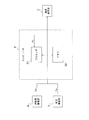
- FIG. 11 is a diagram showing a configuration of an image display device according to a second embodiment of the present invention.
- the image display device according to the second embodiment is generally the same as the image display device according to the first embodiment shown in FIG. However, an illuminance detection unit 6 is added, and a display control device 5b is provided instead of the display control device 5.
- the display control device 5b is generally the same as the display control device 5 of FIG. 1, but an illuminance acquisition unit 16 and a limit value determination unit 17 are added, and the brightness control unit 15b is added instead of the brightness control unit 15 of FIG. To be equipped.
- the illuminance detection unit 6 detects the illuminance around the image display unit 2 in the own vehicle or around the driver, and outputs the detection signal La.
- the illuminance detection unit 6 may be provided in the same housing as the image display unit 2. In the following, it is assumed that the illuminance around the driver is detected.
- the illuminance acquisition unit 16 receives the detection signal La from the illuminance detection unit 6 and acquires and outputs data (illuminance data) Lb indicating the illuminance.
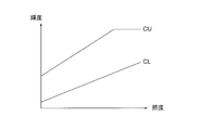
- the limit value determination unit 17 determines the upper limit value CU and the lower limit value CL based on the illuminance data Lb output from the illuminance acquisition unit 16.
- FIG. 12 is a diagram showing an example of an upper limit value CU and a lower limit value CL determined by the limit value determination unit 17.
- the limit value determination unit 17 stores in advance a table (limit value table) showing the relationship between the illuminance and the upper limit value and the lower limit value in an internal memory (not shown), and from the input illuminance, the upper limit value CU and the lower limit value CL. Is determined and output to the brightness control unit 15b.
- the limit value table may have an upper limit value CU and a lower limit value CL for each of the values that the detected illuminance can take, but is not limited to this. That is, for the illuminance having the upper limit value and the lower limit value discretely with respect to the illuminance value and not having the upper limit value and the lower limit value, the corresponding upper limit value and the lower limit value may be obtained by interpolation. This interpolation can be performed, for example, by using the upper limit value and the lower limit value corresponding to the illuminance value (table point) having the upper limit value and the lower limit value.
- the luminance control unit 15b receives the line-of-sight determination information LS output from the line-of-sight detection unit 13, the glare information GZ output from the glare detection unit 14, the other factor FC described above, and the limit value determination unit 17.
- the brightness level of the display image in the image display unit 2 is determined based on the upper limit value CU and the lower limit value CL. Specifically, the emission brightness of the backlight is determined.
- the determination of the luminance level based on the line-of-sight determination information LS, the glare information GZ, and the other factor FC is performed in the same manner as described in the first embodiment.
- the brightness control unit 15b sets the upper limit CU when the brightness level determined based on the line-of-sight determination information LS, the glare information GZ, and other factor FC, that is, the emission brightness of the backlight 22 exceeds the upper limit CU. Do not exceed the lower limit CL, and if it falls below the lower limit CL, do not fall below the lower limit CL. This process is performed, for example, by clipping. That is, the value above the upper limit CU is changed to match the upper limit CU, and the value below the lower limit CL is changed to match the lower limit CL.
- the display control device 5b of FIG. 11 may be partially or wholly composed of a processing circuit.
- the processing circuit may be configured by, for example, a computer similar to that shown in FIG.
- the procedure of processing by the processor 91 when the display control device 5b described above is configured by a similar computer will be described with reference to FIG.
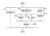
- the processing procedure shown in FIG. 13 is generally the same as the processing procedure shown in FIG. However, steps ST11 and ST12 are added, and step ST6 is replaced with step ST6b.
- step ST11 data indicating the illuminance is acquired and output.
- step ST12 the upper limit value CU and the lower limit value CL are determined.
- step ST6b the brightness is controlled. This process is the same as the process in the luminance control unit 15b of FIG.
- the luminance control unit 15b determines the upper limit value CU and the lower limit value CL according to the illuminance, and controls so that the luminance level of the displayed image does not exceed the upper limit value CU and does not fall below the lower limit value CL. It is possible to prevent the brightness of the displayed image from becoming excessively high or low.
- both the upper limit value CU and the lower limit value CL are used, but only one of the upper limit value CU and the lower limit value CL may be used. That is, the limit value determination unit 17 determines only one of the upper limit value CU and the lower limit value CL, and the brightness control unit does not exceed the upper limit value CU or the lower limit value CL so that the brightness level of the displayed image does not exceed the upper limit value CU.
- the control may be performed by 15b.
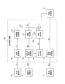
- FIG. 14 is a diagram showing a configuration of an image display device according to a third embodiment of the present invention.
- the image display device according to the third embodiment is generally the same as the image display device according to the first embodiment shown in FIG.
- the peripheral imaging unit 3 of FIG. 1 is not provided, an image supply source 7 is provided instead, and a display control device 5c is provided instead of the display control device 5.
- the display control device 5c is generally the same as the display control device 5 of FIG. 1, but is not provided with the peripheral image acquisition unit 11, but is provided with an image receiving unit 18 instead.
- the image supply source 7 supplies an image Ga other than the peripheral image.
- the image other than the peripheral image is, for example, a car navigation image, an image representing an instrument, or the like.
- the instrument referred to here is, for example, an instrument included in the instrument panel of a vehicle, for example, a speedometer, a fuel gauge, or the like.
- the image receiving unit 18 receives the image Ga supplied from the image supply source 7, converts it into a form suitable for display on the image display unit 2, and outputs the image Gb obtained by the conversion.
- the image display unit 2 displays the image Gb output from the image receiving unit 18 on the display panel 21.
- the image display unit 2 also controls the brightness of the backlight 22 according to the brightness control signal BA output from the brightness control unit 15. Therefore, the visibility of the displayed image can be improved according to both the glare of the image display unit 2 and the glare of the outside light for the driver.
- the display control device 5c of FIG. 14 may be partially or wholly composed of a processing circuit.
- the processing circuit may be configured by, for example, a computer similar to that shown in FIG.
- the procedure of processing by the processor 91 when the display control device 5c described above is configured by a similar computer will be described with reference to FIG.
- step ST1 of FIG. 10 is not provided, and step ST21 is provided instead.
- step ST21 the image Ga is received and converted, and the converted image Gb is output. This process is the same as the process in the image receiving unit 18 of FIG.
- the same effect as that of the first embodiment can be obtained even when an image other than the peripheral image is displayed on the image display unit 2.
- Embodiment 4 the image display unit 2 shown in FIG. 2 is used.
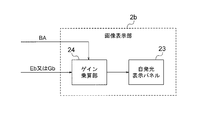
- the image display unit 2b shown in FIG. 16 may be used.
- the image display unit 2b shown in FIG. 16 includes a self-luminous display panel 23 and a gain multiplication unit 24.
- the self-luminous display panel 23 is composed of, for example, an organic EL (Electroluminescence) panel.
- the gain multiplication unit 24 determines the gain according to the luminance control signal BA, and multiplies the determined gain by the image data representing the image Eb or Gb. A larger gain is used when increasing the luminance level, and a smaller gain is used when decreasing the luminance level.
- the self-luminous display panel 23 displays an image based on the image data obtained as a result of the multiplication in the gain multiplication unit 24.
- the image display unit 2b controls the brightness level of the displayed image by determining the gain according to the brightness control signal BA. Also in the fourth embodiment, the same effects as those of the first to third embodiments can be obtained.
- Embodiment 5 The following modifications can be made to the set of rules regarding the adjustment of the brightness level in the brightness control unit 15 or 15b.
- the set of rules shown in FIG. 17 can be used instead of the set of rules described with reference to FIG.
- the set of rules shown in FIG. 17 is generally the same as the set of rules shown in FIG. However, instead of the above rules (a11) to (a13), the following rule (a1) is used.
- the process of maximizing the brightness level of the displayed image is performed by maximizing the emission brightness of the backlight 22.
- the above "maximum” means the upper limit value CU. This is because clipping is performed.
- the process of maximizing the brightness level of the display image is the image obtained as a result of the multiplication by the gain multiplication unit 24.
- the maximum gradation value of the data should be the maximum value within the range of values that can be accepted by the display panel.
- the rule (a1) is applied to the configuration obtained by adding the modification of the fourth embodiment to the second embodiment, the above "maximum value" means the upper limit value CU. This is because clipping is performed.
- the glare level when looking at the outside of the image display unit 2 is “high”, the glare when looking at the image display unit 2 Since the brightness of the image display unit 2 is maximized regardless of the level, the visibility of the displayed image can be improved even when the driver feels that the outside light is dazzling.
- Embodiment 6 instead of the set of rules described with reference to FIG. 5, the set of rules shown in FIG. 18 can also be used.
- the set of rules shown in FIG. 18 is generally the same as the set of rules shown in FIG. However, instead of the above rule (a11), the following rule (a11b) is used. (A11b) When the glare level when looking at the outside of the image display unit 2 is "high” and the glare level when looking at the image display unit 2 is "high”, the brightness level of the displayed image is lowered. Let me.
- the sixth embodiment assumes that the light received by the driver from the image display unit is stronger than the light received from the outside light.
- the glare level when looking at the outside of the image display unit 2 is "high” according to the above rule (a11b), and the image display unit.
- the glare level when looking at 2 is "high”
- the brightness level of the displayed image is lowered, so that the glare of the image display unit 2 can be reduced and the visibility of the displayed image is improved.
- the image display device includes one image display unit.
- two or more display control devices corresponding to the image display units may be provided, and each display control device may control the display in the corresponding image display unit. ..
- at least a part of the peripheral image pickup unit 3, the driver image pickup section 4, the illuminance detection section 6, and the image supply source 7 may be shared.
- a part of two or more display control devices may be shared.
- a portion of the driver image acquisition unit 12, the glare detection unit 14, and the line-of-sight detection unit 13 that detects the line of sight may be shared.
- a single display control device having the above-mentioned common portion and a portion provided corresponding to each image display unit may be configured.
- the display control device constituting the image display device, the image display method implemented by the image display device, and the display control method implemented by the display control device are also a part of the present invention.
- a program that causes a computer to execute a process in the above-mentioned display control device or display control method, and a computer-readable recording medium that records the program, for example, a non-temporary recording medium, also form a part of the present invention.
- 2,2b image display unit 3 peripheral image acquisition unit, 4 driver imaging unit, 5,5b, 5c display control device, 6 illuminance detection unit, 7 image supply source, 11 peripheral image acquisition unit, 12 driver image acquisition unit, 13 line-of-sight detection unit, 14, 14b, 14c glare detection unit, 15, 15b brightness control unit, 16 illuminance acquisition unit, 17 limit value determination unit, 18 image reception unit, 21 display panel, 22 backlight, 23 self-luminous display Panel, 24 gain multiplication unit, 41 pupil diameter information acquisition unit, 42 facial muscle information acquisition unit, 43, 43b, 43c glare calculation unit.
Abstract
The present invention involves: (13) detecting the line of sight of a driver from an image of the driver obtained by means of imaging, and determining from the detected line of sight whether the driver is looking at an image display unit or outside the image display unit; (14) detecting the glare felt by the driver from the image of the driver; and (15) determining the luminance level of the displayed image on the image display unit on the basis of the glare when looking at the image display unit and the glare when looking outside the image display unit. For example, if the glare when the driver is looking at the image display unit is large and the glare when the driver is looking outside the image display unit is large, the luminance level of the display image is increased. Thus, even when the driver feels dazzled by external light entering the eyes, the visibility of the display image can be improved.
Description
本発明は、画像表示装置、表示制御装置、及び表示制御方法に関する。本発明は特に、車両内に搭載された画像表示部に表示される画像の視認性の向上に関する。本発明はまた、プログラム及び記録媒体に関する。
The present invention relates to an image display device, a display control device, and a display control method. The present invention particularly relates to improving the visibility of an image displayed on an image display unit mounted in a vehicle. The present invention also relates to programs and recording media.
近年、バックミラー、サイドミラーとして用いられる物理鏡の代わりとして、電子ミラー装置が提案されている。電子ミラー装置は、車両の後方等に向けられたカメラでの撮像で得られた画像を表示装置で表示するものである。
In recent years, an electronic mirror device has been proposed as an alternative to a physical mirror used as a rearview mirror and a side mirror. The electronic mirror device displays an image obtained by imaging with a camera directed to the rear of the vehicle or the like on a display device.
そのような表示装置においては、表示の輝度をどのように調整するかが一つの課題である。
例えば特許文献1には、ドライバモニタリングシステム(DMS)で得られた運転者の画像から、運転者の瞳孔径を取得し、取得した瞳孔径と予め記憶された径との差に基づいて表示の輝度を制御する技術が提案されている。 In such a display device, how to adjust the brightness of the display is one of the issues.
For example, inPatent Document 1, the pupil diameter of the driver is acquired from the image of the driver obtained by the driver monitoring system (DMS), and is displayed based on the difference between the acquired pupil diameter and the diameter stored in advance. A technique for controlling brightness has been proposed.
例えば特許文献1には、ドライバモニタリングシステム(DMS)で得られた運転者の画像から、運転者の瞳孔径を取得し、取得した瞳孔径と予め記憶された径との差に基づいて表示の輝度を制御する技術が提案されている。 In such a display device, how to adjust the brightness of the display is one of the issues.
For example, in
特許文献1の技術では、表示の輝度が適切に制御されない場合がある。例えば、昼間など照度が高い環境下で運転者が車両内の表示画面を見ている場合、運転者の目に外光が入って、眩しく感じる場合がある。同様に夜間での運転中に、対向車のライト等が運転者の目に入って、眩しく感じる場合がある。このような場合、特許文献1の教示に従って表示の輝度を下げると、表示画像の視認性が低下してしまう。
In the technique of Patent Document 1, the brightness of the display may not be properly controlled. For example, when the driver is looking at the display screen in the vehicle in an environment with high illuminance such as daytime, the driver's eyes may get outside light and feel dazzling. Similarly, while driving at night, the lights of an oncoming vehicle may get into the driver's eyes and feel dazzling. In such a case, if the brightness of the display is lowered according to the teaching of Patent Document 1, the visibility of the displayed image is lowered.
以上、画像表示装置により、車両の周辺の画像が表示される場合について述べたが、車両の周辺の画像以外の画像、例えばカーナビゲーション装置から供給される画像が表示される場合にも同様の問題がある。
The case where the image around the vehicle is displayed by the image display device has been described above, but the same problem occurs when an image other than the image around the vehicle, for example, an image supplied from the car navigation device is displayed. There is.
本発明の目的は、運転者の目に外光が入って眩しいと感じる場合にも、表示画像の視認性を高め得るようにすることである。
An object of the present invention is to improve the visibility of the displayed image even when the driver feels dazzling due to external light entering the eyes.
本発明の画像表示装置は、
車両内に搭載され、画像を表示する画像表示部と、
前記車両の運転者を撮像する運転者撮像部と、
前記運転者撮像部での撮像で得られた画像から、前記運転者の画像を取得し、前記運転者の画像から前記運転者の視線を検出し、検出された視線と、前記画像表示部の位置を示す情報とから前記運転者が前記画像表示部を見ているか、前記画像表示部の外部を見ているか否かを判定し、前記運転者の画像から前記運転者が感じている眩しさを検出し、前記画像表示部を見ている時の眩しさと前記画像表示部の外部を見ている時の眩しさとから前記画像表示部における表示画像の輝度レベルを決定する表示制御装置とを備え、
前記画像表示部は、前記表示制御装置で決定された輝度レベルで、画像を表示する。 The image display device of the present invention
An image display unit that is installed in the vehicle and displays images,
A driver imaging unit that captures the driver of the vehicle,
The image of the driver is acquired from the image obtained by the image captured by the driver imaging unit, the line of sight of the driver is detected from the image of the driver, and the detected line of sight and the image display unit are used. It is determined from the information indicating the position whether the driver is looking at the image display unit or the outside of the image display unit, and the glare felt by the driver from the image of the driver. Is provided, and a display control device for determining the brightness level of the display image in the image display unit from the glare when looking at the image display unit and the glare when looking at the outside of the image display unit is provided. ,
The image display unit displays an image at a brightness level determined by the display control device.
本発明の表示制御装置は、
車両内に搭載され、画像を表示する画像表示部における表示画像の輝度を調整する表示制御装置において、
撮像で得られた運転者の画像から前記運転者の視線を検出し、検出された視線と、前記画像表示部の位置を示す情報とから前記運転者が前記画像表示部を見ているか、前記画像表示部の外部を見ているかを判定する視線検出部と、
前記運転者の画像から前記運転者が感じている眩しさを検出する眩しさ検出部と、
前記画像表示部を見ている時の眩しさと前記画像表示部の外部を見ている時の眩しさとから前記画像表示部における表示画像の輝度レベルを決定する輝度制御部と
を備え、
前記画像表示部に、前記輝度制御部で決定された輝度レベルで、画像を表示させる。 The display control device of the present invention
In a display control device that is mounted in a vehicle and adjusts the brightness of a display image in an image display unit that displays an image.
The driver's line of sight is detected from the driver's image obtained by imaging, and the driver is looking at the image display unit from the detected line of sight and information indicating the position of the image display unit. A line-of-sight detection unit that determines whether you are looking outside the image display unit,
A glare detection unit that detects the glare felt by the driver from the driver's image, and
It is provided with a brightness control unit that determines the brightness level of the displayed image in the image display unit from the glare when looking at the image display unit and the glare when looking at the outside of the image display unit.
The image display unit displays an image at a brightness level determined by the brightness control unit.
本発明によれば、運転者の目に外光が入って眩しいと感じる場合にも、表示画像の視認性を高めることができる。
According to the present invention, the visibility of the displayed image can be improved even when the driver feels dazzling due to external light entering the eyes.
実施の形態1.
図1は、本発明の実施の形態1に係る画像表示装置の構成を示す図である。
図示の画像表示装置は、画像表示部2と、周辺撮像部3と、運転者撮像部4と、表示制御装置5とを有する。Embodiment 1.
FIG. 1 is a diagram showing a configuration of an image display device according to a first embodiment of the present invention.
The illustrated image display device includes animage display unit 2, a peripheral image pickup unit 3, a driver image pickup section 4, and a display control device 5.
図1は、本発明の実施の形態1に係る画像表示装置の構成を示す図である。
図示の画像表示装置は、画像表示部2と、周辺撮像部3と、運転者撮像部4と、表示制御装置5とを有する。
FIG. 1 is a diagram showing a configuration of an image display device according to a first embodiment of the present invention.
The illustrated image display device includes an
画像表示部2は、車両内に搭載されており、運転者が表示画面を見るのに適した位置に配置されている。運転者は運転席に座っている人である。
以下、画像表示部2が搭載された車両を自車両と言うことがある。
画像表示部2は、例えば図2に示されるように、表示パネル21及びバックライト22を有する。表示パネル21は、例えば透過型の表示パネル、例えば透過型のLCD(Liquid Crystal Display)パネルで構成されている。バックライト22は、表示パネル21の背面側に設けられている。 Theimage display unit 2 is mounted in the vehicle and is arranged at a position suitable for the driver to see the display screen. The driver is the person sitting in the driver's seat.
Hereinafter, the vehicle on which theimage display unit 2 is mounted may be referred to as a own vehicle.
Theimage display unit 2 has a display panel 21 and a backlight 22, as shown in FIG. 2, for example. The display panel 21 is composed of, for example, a transmissive display panel, for example, a transmissive LCD (Liquid Crystal Display) panel. The backlight 22 is provided on the back side of the display panel 21.
以下、画像表示部2が搭載された車両を自車両と言うことがある。
画像表示部2は、例えば図2に示されるように、表示パネル21及びバックライト22を有する。表示パネル21は、例えば透過型の表示パネル、例えば透過型のLCD(Liquid Crystal Display)パネルで構成されている。バックライト22は、表示パネル21の背面側に設けられている。 The
Hereinafter, the vehicle on which the
The
周辺撮像部3は、例えば1以上のカメラを含み、自車両の周辺を撮像して、撮像で得られた画像Eaを出力する。
The peripheral imaging unit 3 includes, for example, one or more cameras, images the periphery of the own vehicle, and outputs the image Ea obtained by the imaging.
運転者撮像部4は、例えば1以上のカメラを含み、運転者を撮像して、撮像で得られた画像Daを出力する。
The driver imaging unit 4 includes, for example, one or more cameras, images the driver, and outputs the image Da obtained by the imaging.
表示制御装置5は、周辺撮像部3から出力される画像Eaを受け、該画像又はこれを処理することで得られる画像を画像表示部2に表示させる。
表示制御装置5は、運転者撮像部4から出力される画像Daに基づいて、運転者が感じている眩しさを検出するとともに、運転者が画像表示部2を見ているか、画像表示部2の外部を見ているかを判定し、上記の検出の結果及び上記の判定の結果に基づいて輝度レベルを決定し、画像表示部2で表示される画像の輝度レベルを制御する。 Thedisplay control device 5 receives the image Ea output from the peripheral imaging unit 3, and causes the image display unit 2 to display the image or an image obtained by processing the image Ea.
Thedisplay control device 5 detects the glare felt by the driver based on the image Da output from the driver imaging unit 4, and whether the driver is looking at the image display unit 2 or the image display unit 2 It is determined whether or not the image is viewed from the outside, the brightness level is determined based on the result of the above detection and the result of the above determination, and the brightness level of the image displayed by the image display unit 2 is controlled.
表示制御装置5は、運転者撮像部4から出力される画像Daに基づいて、運転者が感じている眩しさを検出するとともに、運転者が画像表示部2を見ているか、画像表示部2の外部を見ているかを判定し、上記の検出の結果及び上記の判定の結果に基づいて輝度レベルを決定し、画像表示部2で表示される画像の輝度レベルを制御する。 The
The
表示制御装置5は、周辺画像取得部11、運転者画像取得部12、視線検出部13、眩しさ検出部14、及び輝度制御部15を備える。
The display control device 5 includes a peripheral image acquisition unit 11, a driver image acquisition unit 12, a line-of-sight detection unit 13, a glare detection unit 14, and a brightness control unit 15.
周辺画像取得部11は、周辺撮像部3から出力される画像Eaを受け、自車両の周辺の状況を表す画像(周辺画像)Ebを取得し、出力する。
周辺撮像部3が1個のカメラで構成される場合、周辺画像取得部11は、該カメラでの撮像で得られた画像をそのまま周辺画像Ebとして出力しても良く、該カメラでの撮像で得られた画像の一部を切り出して、周辺画像Ebとして出力しても良い。 The peripheralimage acquisition unit 11 receives the image Ea output from the peripheral image pickup unit 3, acquires an image (peripheral image) Eb showing the situation around the own vehicle, and outputs the image Eb.
When the peripheralimage pickup unit 3 is composed of one camera, the peripheral image acquisition unit 11 may output the image obtained by imaging with the camera as it is as the peripheral image Eb, and the peripheral image acquisition unit 11 may output the image obtained by the camera as it is. A part of the obtained image may be cut out and output as a peripheral image Eb.
周辺撮像部3が1個のカメラで構成される場合、周辺画像取得部11は、該カメラでの撮像で得られた画像をそのまま周辺画像Ebとして出力しても良く、該カメラでの撮像で得られた画像の一部を切り出して、周辺画像Ebとして出力しても良い。 The peripheral
When the peripheral
周辺撮像部3が2以上のカメラで構成される場合、周辺画像取得部11は、2以上のカメラのいずれかでの撮像で得られた画像を選択し、選択した画像をそのまま周辺画像Ebとして出力しても良く、選択した画像の一部を切り出して周辺画像Ebとして出力しても良い。また、周辺画像取得部11は、2以上のカメラでの撮像で得られた画像に基づいて合成画像を生成して、生成した合成画像を周辺画像Ebとして出力しても良い。
When the peripheral image pickup unit 3 is composed of two or more cameras, the peripheral image acquisition unit 11 selects an image obtained by imaging with one of the two or more cameras, and uses the selected image as the peripheral image Eb as it is. It may be output, or a part of the selected image may be cut out and output as a peripheral image Eb. Further, the peripheral image acquisition unit 11 may generate a composite image based on the images obtained by imaging with two or more cameras, and output the generated composite image as the peripheral image Eb.
周辺画像取得部11は、自車両の固定された方向の画像を、周辺画像Ebとして出力しても良い。代わりに、自車両の運転状況に応じて異なる方向の画像を周辺画像Ebとして出力しても良い。例えば、右折を行うとき、左折を行うとき、車線を変更するとき、後進するときなど、各々の場合に運転における必要性の程度の高い方向の画像を周辺画像Ebとして出力することとしても良い。
The peripheral image acquisition unit 11 may output an image of the own vehicle in a fixed direction as a peripheral image Eb. Alternatively, an image in a different direction may be output as a peripheral image Eb according to the driving situation of the own vehicle. For example, when making a right turn, making a left turn, changing lanes, moving backward, etc., an image in a direction with a high degree of necessity for driving may be output as a peripheral image Eb.
画像表示部2は周辺画像取得部11から出力される周辺画像Ebを表示パネル21に表示する。
The image display unit 2 displays the peripheral image Eb output from the peripheral image acquisition unit 11 on the display panel 21.
運転者画像取得部12は、運転者撮像部4から出力される画像Daを受け、運転者の画像(運転者画像)Dbを取得し、出力する。運転者画像Dbは、運転者の顔を含む画像である。
運転者撮像部4が1個のカメラで構成される場合、運転者画像取得部12は、該カメラでの撮像で得られた画像をそのまま運転者画像Dbとして出力しても良く、該カメラでの撮像で得られた画像の一部を切り出して、運転者画像Dbとして出力しても良い。
例えば、カメラでの撮像で得られる画像は、運転者のみならず、運転者の周囲をも含むものであり、そのような画像の一部を切り出すことで得られた画像を運転者画像Dbとして出力しても良い。 The driverimage acquisition unit 12 receives the image Da output from the driver image pickup unit 4, acquires the driver image (driver image) Db, and outputs the image Da. The driver image Db is an image including the driver's face.
When the driverimage pickup unit 4 is composed of one camera, the driver image acquisition unit 12 may output the image obtained by the image pickup by the camera as it is as the driver image Db, and the camera may output the image. A part of the image obtained by the imaging of the above may be cut out and output as a driver image Db.
For example, the image obtained by capturing with a camera includes not only the driver but also the surroundings of the driver, and the image obtained by cutting out a part of such an image is used as the driver image Db. You may output it.
運転者撮像部4が1個のカメラで構成される場合、運転者画像取得部12は、該カメラでの撮像で得られた画像をそのまま運転者画像Dbとして出力しても良く、該カメラでの撮像で得られた画像の一部を切り出して、運転者画像Dbとして出力しても良い。
例えば、カメラでの撮像で得られる画像は、運転者のみならず、運転者の周囲をも含むものであり、そのような画像の一部を切り出すことで得られた画像を運転者画像Dbとして出力しても良い。 The driver
When the driver
For example, the image obtained by capturing with a camera includes not only the driver but also the surroundings of the driver, and the image obtained by cutting out a part of such an image is used as the driver image Db. You may output it.
運転者撮像部4が2以上のカメラで構成される場合、運転者画像取得部12は、2以上のカメラのいずれかでの撮像で得られた画像を選択し、選択した画像をそのまま運転者画像Dbとして出力しても良く、選択した画像の一部を切り出して運転者画像Dbとして出力しても良い。また、2以上のカメラを用い、運転者を異なる方向から撮像することで得られた、2以上の画像を、それぞれ運転者画像Dbとして出力しても良く、そのような2以上の画像を合成することで得られる画像を運転者画像Dbとして出力しても良い。
When the driver image pickup unit 4 is composed of two or more cameras, the driver image acquisition unit 12 selects an image obtained by imaging with one of the two or more cameras, and the selected image is used as it is by the driver. It may be output as an image Db, or a part of the selected image may be cut out and output as a driver image Db. Further, two or more images obtained by photographing the driver from different directions using two or more cameras may be output as a driver image Db, and such two or more images may be combined. The image obtained by the above may be output as the driver image Db.
視線検出部13は、運転者画像取得部12から出力される運転者画像Dbから視線を検出する。視線の検出は、視点の位置の検出及び視線の方向の検出を含む。
視線検出部13は運転者の顔の向きと運転者の左右の目の瞳孔の位置とから視線を算出しても良い。 The line-of-sight detection unit 13 detects the line of sight from the driver image Db output from the driver image acquisition unit 12. Line-of-sight detection includes detection of the position of the viewpoint and detection of the direction of the line of sight.
The line-of-sight detection unit 13 may calculate the line-of-sight from the direction of the driver's face and the positions of the pupils of the driver's left and right eyes.
視線検出部13は運転者の顔の向きと運転者の左右の目の瞳孔の位置とから視線を算出しても良い。 The line-of-
The line-of-
視線検出部13はさらに、上記の視線検出の結果と、図示しない内部のメモリに予め記憶されている画像表示部2の位置を示す情報PLとから、運転者が画像表示部2を見ているか、画像表示部2の外部を見ているかを判定し、判定結果を示す情報(視線判定情報)LSを出力する。
The line-of-sight detection unit 13 further determines whether the driver is looking at the image display unit 2 from the result of the line-of-sight detection and the information PL indicating the position of the image display unit 2 stored in advance in an internal memory (not shown). , It is determined whether or not the outside of the image display unit 2 is being viewed, and information (line-of-sight determination information) LS indicating the determination result is output.
画像表示部2を見ているか、画像表示部2の外部を見ているかの判定においては、画像表示部2の特定の部分、例えば表示画面の中央部を見ている時に限り、画像表示部2を見ていると判定しても良いし、画像表示部2より少し広い範囲内のいずれかの点を見ている時も画像表示部2を見ていると判定しても良い。
In determining whether the image display unit 2 is being viewed or the outside of the image display unit 2 is being viewed, the image display unit 2 is limited to viewing a specific portion of the image display unit 2, for example, the central portion of the display screen. It may be determined that the image is being viewed, or it may be determined that the image display unit 2 is being viewed even when the user is looking at any point within a range slightly wider than the image display unit 2.
画像表示部2の外部を見ているとの判定を行なうに当たっては、運転者が画像表示部2の外部の特定の方向を見ているとき、例えば運転者が前方を見ている時のみ、「画像表示部2の外部を見ている」と判定しても良い。また、「画像表示部2を見ている時」に該当しない場合は全て「画像表示部2の外部を見ている」と判定しても良い。後者の場合、「画像表示部2の外部を見ている時」には、視点が定まらず格別どこも見ていない時が含まれる。
In determining that the image display unit 2 is looking outside, only when the driver is looking in a specific direction outside the image display unit 2, for example, when the driver is looking ahead, " It may be determined that "the outside of the image display unit 2 is being viewed". Further, if it does not correspond to "when looking at the image display unit 2", it may be determined that "looking at the outside of the image display unit 2". In the latter case, "when looking at the outside of the image display unit 2" includes a time when the viewpoint is not fixed and no one is looking at anything.
眩しさ検出部14は、運転者画像取得部12から出力される運転者画像Dbから運転者が感じている眩しさレベルを検出し、検出した眩しさレベルを示す情報(眩しさ情報)GZを出力する。
The glare detection unit 14 detects the glare level felt by the driver from the driver image Db output from the driver image acquisition unit 12, and outputs information (glare information) GZ indicating the detected glare level. Output.
眩しさ検出部14は、例えば、図3に示すように、瞳孔径情報取得部41、表情筋情報取得部42、及び眩しさ算出部43を有する。
As shown in FIG. 3, the glare detection unit 14 includes, for example, a pupil diameter information acquisition unit 41, a facial muscle information acquisition unit 42, and a glare calculation unit 43.
瞳孔径情報取得部41は、瞳孔径Dpを測定し、測定された瞳孔径Dpを示す情報(瞳孔径情報)を取得し、出力する。
表情筋情報取得部42は、運転者の顔の画像から表情筋の特徴量Fmを検出し、検出された特徴量Fmを示す情報(表情筋情報)を取得し、出力する。
眩しさ算出部43は、瞳孔径情報取得部41から出力される瞳孔径情報で表される瞳孔径Dpと、表情筋情報取得部42から出力される表情筋情報で表される特徴量Fmとから、運転者にとっての眩しさを算出する。 The pupil diameterinformation acquisition unit 41 measures the pupil diameter Dp, acquires information indicating the measured pupil diameter Dp (pupil diameter information), and outputs the information (pupil diameter information).
The facial muscleinformation acquisition unit 42 detects the feature amount Fm of the facial muscle from the image of the driver's face, acquires information indicating the detected feature amount Fm (facial muscle information), and outputs the information (facial muscle information).
Theglare calculation unit 43 includes a pupil diameter Dp represented by pupil diameter information output from the pupil diameter information acquisition unit 41 and a feature amount Fm represented by facial muscle information output from the facial muscle information acquisition unit 42. From, the glare for the driver is calculated.
表情筋情報取得部42は、運転者の顔の画像から表情筋の特徴量Fmを検出し、検出された特徴量Fmを示す情報(表情筋情報)を取得し、出力する。
眩しさ算出部43は、瞳孔径情報取得部41から出力される瞳孔径情報で表される瞳孔径Dpと、表情筋情報取得部42から出力される表情筋情報で表される特徴量Fmとから、運転者にとっての眩しさを算出する。 The pupil diameter
The facial muscle
The
図4(a)及び(b)は、人の目の瞳孔PP及びその周囲の虹彩IRを示す。一般的に網膜に投射する光量を調節するために、虹彩IRの伸縮により瞳孔PPの大きさが変えられる。瞳孔径Dpは、眩しい状況では図4(a)に示すように小さくなり、暗い場所では図4(b)に示すように大きくなる。
瞳孔径情報取得部41は運転者の顔の画像の目の領域から瞳孔径Dpを測定し、測定結果を眩しさ算出部43へ出力する。 4 (a) and 4 (b) show the pupil PP of the human eye and the iris IR around it. Generally, in order to adjust the amount of light projected on the retina, the size of the pupil PP is changed by the expansion and contraction of the iris IR. The pupil diameter Dp becomes smaller as shown in FIG. 4 (a) in a dazzling situation and becomes larger as shown in FIG. 4 (b) in a dark place.
The pupil diameterinformation acquisition unit 41 measures the pupil diameter Dp from the eye region of the image of the driver's face, and outputs the measurement result to the glare calculation unit 43.
瞳孔径情報取得部41は運転者の顔の画像の目の領域から瞳孔径Dpを測定し、測定結果を眩しさ算出部43へ出力する。 4 (a) and 4 (b) show the pupil PP of the human eye and the iris IR around it. Generally, in order to adjust the amount of light projected on the retina, the size of the pupil PP is changed by the expansion and contraction of the iris IR. The pupil diameter Dp becomes smaller as shown in FIG. 4 (a) in a dazzling situation and becomes larger as shown in FIG. 4 (b) in a dark place.
The pupil diameter
また、眩しさに応じて目を細めると、目の周辺を含む顔の表情筋の状態も変化する。表情筋情報取得部42は運転者の顔の画像から表情筋の特徴量Fmを検出し、検出結果を眩しさ算出部43へ出力する。ここで言う表情筋の特徴量Fmは、眩しさのために目を細める際の表情筋の状態の変化によって大きくなる量であり、各時点における表情筋の状態を表す量であっても良く、時間の経過に伴う変化に基づいて算出される量、例えば、上記の変化の量を積算することで求められる量であっても良い。
Also, if you squint according to the glare, the condition of the facial muscles including the area around the eyes will change. The facial muscle information acquisition unit 42 detects the feature amount Fm of the facial muscle from the image of the driver's face, and outputs the detection result to the glare calculation unit 43. The feature amount Fm of the facial muscles referred to here is an amount that increases due to a change in the state of the facial muscles when squinting due to glare, and may be an amount that represents the state of the facial muscles at each time point. It may be an amount calculated based on a change with the passage of time, for example, an amount obtained by integrating the amount of the above change.
眩しさ算出部43では瞳孔径Dpと表情筋の特徴量Fmとから眩しさレベルを算出し、算出した眩しさレベルを示す情報(眩しさ情報)GZを出力する。
例えば、瞳孔径Dpが小さいほど眩しさの程度は大きく、瞳孔径Dpが大きければ眩しさの程度は小さいと判定する。また、表情筋の特徴量Fmが大きいほど眩しさの程度が大きいと判定する。眩しさ算出部43は、これらの判定結果を統合して、眩しさを判定する。
例えば、眩しさが大きさに応じて、眩しさレベルが「高」、「中」、「低」のいずれであるかを判定する。 Theglare calculation unit 43 calculates the glare level from the pupil diameter Dp and the feature amount Fm of the facial muscles, and outputs the information (glare information) GZ indicating the calculated glare level.
For example, it is determined that the smaller the pupil diameter Dp, the greater the degree of glare, and the larger the pupil diameter Dp, the smaller the degree of glare. Further, it is determined that the larger the feature amount Fm of the facial muscle, the greater the degree of glare. Theglare calculation unit 43 integrates these determination results to determine glare.
For example, it is determined whether the glare level is "high", "medium", or "low" according to the magnitude of the glare.
例えば、瞳孔径Dpが小さいほど眩しさの程度は大きく、瞳孔径Dpが大きければ眩しさの程度は小さいと判定する。また、表情筋の特徴量Fmが大きいほど眩しさの程度が大きいと判定する。眩しさ算出部43は、これらの判定結果を統合して、眩しさを判定する。
例えば、眩しさが大きさに応じて、眩しさレベルが「高」、「中」、「低」のいずれであるかを判定する。 The
For example, it is determined that the smaller the pupil diameter Dp, the greater the degree of glare, and the larger the pupil diameter Dp, the smaller the degree of glare. Further, it is determined that the larger the feature amount Fm of the facial muscle, the greater the degree of glare. The
For example, it is determined whether the glare level is "high", "medium", or "low" according to the magnitude of the glare.
眩しさレベルは、「高」、「中」、「低」の3段階としたが段階の数は2であっても良く3より多くても良い。例えば、10段階程度であっても良い。
The glare level was set to 3 levels of "high", "medium", and "low", but the number of levels may be 2 or more than 3. For example, it may be about 10 steps.
輝度制御部15は、視線検出部13から出力される視線判定情報LSと、眩しさ検出部14から出力される眩しさ情報GZとに基づいて、画像表示部2における表示画像の輝度レベルを決定する。
The brightness control unit 15 determines the brightness level of the display image in the image display unit 2 based on the line-of-sight determination information LS output from the line-of-sight detection unit 13 and the glare information GZ output from the glare detection unit 14. To do.
表示画像の輝度レベルは、視線判定情報LS及び眩しさ情報GZ以外の要因(以下、「他の要因」と言い、符号FCで示す。)をも考慮して決定される。例えば、ユーザによる明るさの設定を表す信号、画像表示部2に入力される画像の明るさに基づく信号にも基づいて定められる。
視線判定情報LS及び眩しさ情報に基づく輝度レベルの決定は、他の要因FCに基づいて決定された輝度レベルに対する調整乃至変更として行われる。 The brightness level of the displayed image is determined in consideration of factors other than the line-of-sight determination information LS and the glare information GZ (hereinafter, referred to as “other factors” and indicated by reference numerals FC). For example, it is determined based on a signal indicating the brightness setting by the user and a signal based on the brightness of the image input to theimage display unit 2.
The determination of the luminance level based on the line-of-sight determination information LS and the glare information is performed as an adjustment or change with respect to the luminance level determined based on the other factor FC.
視線判定情報LS及び眩しさ情報に基づく輝度レベルの決定は、他の要因FCに基づいて決定された輝度レベルに対する調整乃至変更として行われる。 The brightness level of the displayed image is determined in consideration of factors other than the line-of-sight determination information LS and the glare information GZ (hereinafter, referred to as “other factors” and indicated by reference numerals FC). For example, it is determined based on a signal indicating the brightness setting by the user and a signal based on the brightness of the image input to the
The determination of the luminance level based on the line-of-sight determination information LS and the glare information is performed as an adjustment or change with respect to the luminance level determined based on the other factor FC.
輝度レベルの決定は、例えばバックライト22の発光輝度の決定により行われる。
表示画像の各画素の輝度は、バックライト22の発光輝度と、表示パネル21の各画素の駆動に用いられる信号の値(画素値)とによって決まる。 The brightness level is determined, for example, by determining the emission brightness of thebacklight 22.
The brightness of each pixel of the display image is determined by the emission brightness of thebacklight 22 and the value (pixel value) of the signal used to drive each pixel of the display panel 21.
表示画像の各画素の輝度は、バックライト22の発光輝度と、表示パネル21の各画素の駆動に用いられる信号の値(画素値)とによって決まる。 The brightness level is determined, for example, by determining the emission brightness of the
The brightness of each pixel of the display image is determined by the emission brightness of the
表示画像の輝度レベルの調整は以下のように行われる。
輝度制御部15は、各時点で、視線判定情報LSに基づいて、各時点で運転者が画像表示部2を見ているか画像表示部2の外部を見ているかの判断をする。
輝度制御部15は、図示しない内部のメモリに、画像表示部2を見ている時の眩しさレベルと、画像表示部2の外部を見ている時の眩しさレベルとを格納する。
格納されている眩しさレベルは、眩しさレベルを表すデータが新たに取得されると更新される。データの取得は、処理周期毎に行われる。 The brightness level of the displayed image is adjusted as follows.
Theluminance control unit 15 determines at each time point whether the driver is looking at the image display unit 2 or the outside of the image display unit 2 based on the line-of-sight determination information LS.
Thebrightness control unit 15 stores a glare level when looking at the image display unit 2 and a glare level when looking at the outside of the image display unit 2 in an internal memory (not shown).
The stored glare level is updated when new data representing the glare level is acquired. Data acquisition is performed every processing cycle.
輝度制御部15は、各時点で、視線判定情報LSに基づいて、各時点で運転者が画像表示部2を見ているか画像表示部2の外部を見ているかの判断をする。
輝度制御部15は、図示しない内部のメモリに、画像表示部2を見ている時の眩しさレベルと、画像表示部2の外部を見ている時の眩しさレベルとを格納する。
格納されている眩しさレベルは、眩しさレベルを表すデータが新たに取得されると更新される。データの取得は、処理周期毎に行われる。 The brightness level of the displayed image is adjusted as follows.
The
The
The stored glare level is updated when new data representing the glare level is acquired. Data acquisition is performed every processing cycle.
例えば、「運転者が画像表示部2を見ている」と判断された時に検出された眩しさレベルは、「画像表示部2を見ている時の眩しさレベル」として格納される。同様に、「運転者が画像表示部2の外部を見ている」と判断された時に検出された眩しさレベルは、「画像表示部2の外部を見ている時の眩しさレベル」として格納される。
For example, the glare level detected when it is determined that "the driver is looking at the image display unit 2" is stored as "the glare level when the driver is looking at the image display unit 2". Similarly, the glare level detected when it is determined that "the driver is looking at the outside of the image display unit 2" is stored as "the glare level when looking at the outside of the image display unit 2". Will be done.
輝度制御部15は、現時点において、運転者が画像表示部2を見ているか画像表示部2の外部を見ているかの判定結果と、画像表示部2を見ている時の眩しさレベルと、画像表示部2の外部を見ている時の眩しさレベルとから、輝度レベルの調整を行う必要があるか否か、及び調整を行う場合には調整をどのように行うかを決定する。
At present, the luminance control unit 15 determines whether the driver is looking at the image display unit 2 or the outside of the image display unit 2, and the glare level when the driver is looking at the image display unit 2. From the glare level when looking at the outside of the image display unit 2, it is determined whether or not it is necessary to adjust the brightness level, and if so, how to make the adjustment.
現時点で運転者が画像表示部2を見ている場合、「画像表示部2を見ている時の眩しさレベル」は、現時点での眩しさ検出部14にて検出されている眩しさのレベルを意味し、「画像表示部2の外部を見ている時の眩しさレベル」は、輝度制御部15内に格納されている、現時点より前の、「画像表示部2の外部を見ていた時の眩しさのレベル」を意味する。
When the driver is looking at the image display unit 2 at the present time, the "glare level when looking at the image display unit 2" is the level of glare detected by the glare detection unit 14 at the present time. The "glare level when looking at the outside of the image display unit 2" means "looking at the outside of the image display unit 2" before the present time, which is stored in the brightness control unit 15. It means "the level of glare of time".
現時点で運転者が画像表示部2の外部を見ている場合、「画像表示部2の外部を見ている時の眩しさレベル」は、現時点で眩しさ検出部14で検出されている眩しさのレベルを意味し、「画像表示部2を見ている時の眩しさレベル」は、輝度制御部15内に格納されている、現時点より前の、「画像表示部2を見ていた時眩しさのレベル」を意味する。
When the driver is looking at the outside of the image display unit 2 at the present time, the "glare level when looking at the outside of the image display unit 2" is the glare detected by the glare detection unit 14 at the present time. The "glare level when looking at the image display unit 2" means the level of "glare when looking at the image display unit 2" before the present time, which is stored in the brightness control unit 15. It means "the level of the image".
調整をどのように行うかには、調整の程度が含まれる。
調整の程度は、調整の幅、或いは調整に用いる係数を意味する。
調整の幅が用いられる場合、他の要因FCで決定されている輝度レベルに対して、調整の幅が加算又は減算される。輝度レベルを上昇させる場合には、調整の幅が加算され、輝度レベルを低下させる場合には、調整の幅が減算される。上昇させる場合の調整の幅と低下させる場合の調整の幅とが互いに異なっていても良い。
調整の係数が用いられる場合、他の要因FCで決定されている輝度レベルに対して、調整の係数が乗算される。輝度レベルを上昇させる場合には、1より大きい係数が用いられ、輝度レベルを低下させる場合には、1より小さい係数が用いられる。 How the adjustment is made includes the degree of adjustment.
The degree of adjustment means the width of adjustment or the coefficient used for adjustment.
When the adjustment width is used, the adjustment width is added or subtracted with respect to the brightness level determined by the other factor FC. When the brightness level is increased, the adjustment range is added, and when the brightness level is decreased, the adjustment range is subtracted. The width of adjustment when raising and the width of adjustment when lowering may be different from each other.
When the adjustment factor is used, the adjustment factor is multiplied by the brightness level determined by the other factor FC. A coefficient greater than 1 is used to increase the luminance level, and a coefficient less than 1 is used to decrease the luminance level.
本実施の形態では、調整の程度は一定であり、予め定められており、輝度レベルの調整に関する決定においては、輝度レベルを上昇させるべきか、低下させるべきか、或いは維持すべきか、の決定が行われる。
In the present embodiment, the degree of adjustment is constant and predetermined, and in the determination regarding the adjustment of the luminance level, it is determined whether the luminance level should be increased, decreased, or maintained. Will be done.
輝度レベルの調整に関する決定は、例えば図5に示される規則の組に従って行われる。図5に示される規則の組に含まれる規則は以下の通りである。
The decision regarding the adjustment of the brightness level is made according to, for example, a set of rules shown in FIG. The rules included in the set of rules shown in FIG. 5 are as follows.
(a) 現時点で運転者が画像表示部2を見ている場合には以下のように処理する。
(a11) 画像表示部2の外部を見ている時の眩しさレベルが「高」、画像表示部2を見ている時の眩しさレベルが「高」の場合、表示画像の輝度レベルを上昇させる。
(a12) 画像表示部2の外部を見ている時の眩しさレベルが「高」、画像表示部2を見ている時の眩しさレベルが「中」の場合、表示画像の輝度レベルを維持する。
(a13) 画像表示部2の外部を見ている時の眩しさレベルが「高」、画像表示部2を見ている時の眩しさレベルが「低」の場合、表示画像の輝度レベルを上昇させる。
(a21) 画像表示部2の外部を見ている時の眩しさレベルが「中」、画像表示部2を見ている時の眩しさレベルが「高」の場合、表示画像の輝度レベルを低下させる。
(a22) 画像表示部2の外部を見ている時の眩しさレベルが「中」、画像表示部2を見ている時の眩しさレベルが「中」の場合、表示画像の輝度レベルを維持する。
(a23) 画像表示部2の外部を見ている時の眩しさレベルが「中」、画像表示部2を見ている時の眩しさレベルが「低」の場合、表示画像の輝度レベルを上昇させる。
(a31) 画像表示部2の外部を見ている時の眩しさレベルが「低」、画像表示部2を見ている時の眩しさレベルが「高」の場合、表示画像の輝度レベルを低下させる。
(a32) 画像表示部2の外部を見ている時の眩しさレベルが「低」、画像表示部2を見ている時の眩しさレベルが「中」の場合、表示画像の輝度レベルを維持する。
(a33) 画像表示部2の外部を見ている時の眩しさレベルが「低」、画像表示部2を見ている時の眩しさレベルが「低」の場合、表示画像の輝度レベルを上昇させる。
(b) 現時点で運転者が画像表示部2の外部を見ている場合、画像表示部2を見ている時の眩しさレベルと画像表示部2の外部を見ている時の眩しさレベルに関わらず表示画像の輝度レベルを維持する。 (A) If the driver is currently looking at theimage display unit 2, the process is as follows.
(A11) When the glare level when looking at the outside of theimage display unit 2 is "high" and the glare level when looking at the image display unit 2 is "high", the brightness level of the displayed image is increased. Let me.
(A12) When the glare level when looking at the outside of theimage display unit 2 is "high" and the glare level when looking at the image display unit 2 is "medium", the brightness level of the displayed image is maintained. To do.
(A13) When the glare level when looking at the outside of theimage display unit 2 is "high" and the glare level when looking at the image display unit 2 is "low", the brightness level of the displayed image is increased. Let me.
(A21) When the glare level when looking at the outside of theimage display unit 2 is "medium" and the glare level when looking at the image display unit 2 is "high", the brightness level of the displayed image is lowered. Let me.
(A22) When the glare level when looking at the outside of theimage display unit 2 is "medium" and the glare level when looking at the image display unit 2 is "medium", the brightness level of the displayed image is maintained. To do.
(A23) When the glare level when looking at the outside of theimage display unit 2 is "medium" and the glare level when looking at the image display unit 2 is "low", the brightness level of the displayed image is increased. Let me.
(A31) When the glare level when looking at the outside of theimage display unit 2 is "low" and the glare level when looking at the image display unit 2 is "high", the brightness level of the displayed image is lowered. Let me.
(A32) When the glare level when looking at the outside of theimage display unit 2 is “low” and the glare level when looking at the image display unit 2 is “medium”, the brightness level of the displayed image is maintained. To do.
(A33) When the glare level when looking at the outside of theimage display unit 2 is "low" and the glare level when looking at the image display unit 2 is "low", the brightness level of the displayed image is increased. Let me.
(B) When the driver is currently looking at the outside of theimage display unit 2, the glare level when looking at the image display unit 2 and the glare level when looking at the outside of the image display unit 2 are set. Regardless, the brightness level of the displayed image is maintained.
(a11) 画像表示部2の外部を見ている時の眩しさレベルが「高」、画像表示部2を見ている時の眩しさレベルが「高」の場合、表示画像の輝度レベルを上昇させる。
(a12) 画像表示部2の外部を見ている時の眩しさレベルが「高」、画像表示部2を見ている時の眩しさレベルが「中」の場合、表示画像の輝度レベルを維持する。
(a13) 画像表示部2の外部を見ている時の眩しさレベルが「高」、画像表示部2を見ている時の眩しさレベルが「低」の場合、表示画像の輝度レベルを上昇させる。
(a21) 画像表示部2の外部を見ている時の眩しさレベルが「中」、画像表示部2を見ている時の眩しさレベルが「高」の場合、表示画像の輝度レベルを低下させる。
(a22) 画像表示部2の外部を見ている時の眩しさレベルが「中」、画像表示部2を見ている時の眩しさレベルが「中」の場合、表示画像の輝度レベルを維持する。
(a23) 画像表示部2の外部を見ている時の眩しさレベルが「中」、画像表示部2を見ている時の眩しさレベルが「低」の場合、表示画像の輝度レベルを上昇させる。
(a31) 画像表示部2の外部を見ている時の眩しさレベルが「低」、画像表示部2を見ている時の眩しさレベルが「高」の場合、表示画像の輝度レベルを低下させる。
(a32) 画像表示部2の外部を見ている時の眩しさレベルが「低」、画像表示部2を見ている時の眩しさレベルが「中」の場合、表示画像の輝度レベルを維持する。
(a33) 画像表示部2の外部を見ている時の眩しさレベルが「低」、画像表示部2を見ている時の眩しさレベルが「低」の場合、表示画像の輝度レベルを上昇させる。
(b) 現時点で運転者が画像表示部2の外部を見ている場合、画像表示部2を見ている時の眩しさレベルと画像表示部2の外部を見ている時の眩しさレベルに関わらず表示画像の輝度レベルを維持する。 (A) If the driver is currently looking at the
(A11) When the glare level when looking at the outside of the
(A12) When the glare level when looking at the outside of the
(A13) When the glare level when looking at the outside of the
(A21) When the glare level when looking at the outside of the
(A22) When the glare level when looking at the outside of the
(A23) When the glare level when looking at the outside of the
(A31) When the glare level when looking at the outside of the
(A32) When the glare level when looking at the outside of the
(A33) When the glare level when looking at the outside of the
(B) When the driver is currently looking at the outside of the
輝度制御部15は、上記の規則の組に従って輝度レベルの調整を行い、調整後の輝度レベルを示す輝度制御信号BAを出力する。
The brightness control unit 15 adjusts the brightness level according to the set of the above rules, and outputs a brightness control signal BA indicating the adjusted brightness level.
画像表示部2は輝度制御部15からの輝度制御信号BAに応じてバックライト22の輝度を制御する。
輝度制御信号BAで指示される輝度レベルは、画像表示部2の眩しさと外光の眩しさの両方に基づいて調整されたものであるので、画像表示部2における表示画像は、画像表示部2の眩しさ及び外光の眩しさの如何を問わず、視認性が高いものとなる。 Theimage display unit 2 controls the brightness of the backlight 22 according to the brightness control signal BA from the brightness control unit 15.
Since the brightness level indicated by the brightness control signal BA is adjusted based on both the glare of theimage display unit 2 and the glare of the external light, the display image in the image display unit 2 is the image display unit 2. The visibility is high regardless of the glare of the image and the glare of the outside light.
輝度制御信号BAで指示される輝度レベルは、画像表示部2の眩しさと外光の眩しさの両方に基づいて調整されたものであるので、画像表示部2における表示画像は、画像表示部2の眩しさ及び外光の眩しさの如何を問わず、視認性が高いものとなる。 The
Since the brightness level indicated by the brightness control signal BA is adjusted based on both the glare of the
ここで画像表示部2の外光の眩しさレベルを考慮しない構成(比較例)の動作を説明する。図6は比較例における輝度レベル調整の規則の組を示す。図6に示される例では、現時点で運転者が画像表示部2を見ている場合、眩しさレベルが「高」の時には輝度レベルを低下させ、眩しさレベルが「中」の時には輝度レベルを維持し、眩しさレベルが「低」の時には輝度レベルを上昇させる。
Here, the operation of the configuration (comparative example) in which the glare level of the external light of the image display unit 2 is not considered will be described. FIG. 6 shows a set of rules for adjusting the brightness level in the comparative example. In the example shown in FIG. 6, when the driver is currently looking at the image display unit 2, the luminance level is lowered when the glare level is “high”, and the luminance level is set when the glare level is “medium”. Maintain and increase the brightness level when the glare level is "low".
例えば、画像表示部2を見ていても、運転者が外光の影響を強く受けてしまうことがある。例えば夏の晴れた日の昼などは非常に照度が高くて、画像表示部2を見ていても運転者の目に外光が多く入る。また、前方の車両からの反射光、夜の対向車のハイビーム、夕方の夕日など、画像表示部2を見ていても運転者の目に外光が多く入る場合がある。このような状況では外光の影響で画像表示部2の視認性が低下する。この場合、比較例では、画像表示部2を見ている時の眩しさレベルは「高」となるため、輝度レベルを低下させることになり、その結果視認性がさらに低くなる。
For example, even when looking at the image display unit 2, the driver may be strongly affected by the outside light. For example, the illuminance is very high in the daytime on a sunny day in summer, and even when looking at the image display unit 2, a lot of outside light enters the driver's eyes. In addition, a large amount of outside light may enter the driver's eyes even when looking at the image display unit 2, such as reflected light from a vehicle in front, a high beam of an oncoming vehicle at night, or a sunset in the evening. In such a situation, the visibility of the image display unit 2 is lowered due to the influence of external light. In this case, in the comparative example, the glare level when looking at the image display unit 2 is “high”, so that the brightness level is lowered, and as a result, the visibility is further lowered.
これに対し、図5に示される規則の組に従って行われる調整では、外光による眩しさレベルが高い場合には、表示画像の輝度レベルを上昇させる。その結果、表示画像の視認性を高くすることができる。
On the other hand, in the adjustment performed according to the set of rules shown in FIG. 5, when the glare level due to external light is high, the brightness level of the displayed image is increased. As a result, the visibility of the displayed image can be improved.
なお、図3の眩しさ検出部14は、瞳孔径情報取得部41と表情筋情報取得部42とを備えているが、これらのうちの一方のみを備える眩しさ検出部を用いても良い。即ち、図7のように、瞳孔径情報取得部41と眩しさ算出部43bとを備える眩しさ検出部14bを用いても良く、図8のように、表情筋情報取得部42と眩しさ算出部43cとを備える眩しさ検出部14cを用いても良い。図7の眩しさ算出部43bは、瞳孔径情報取得部41から出力される瞳孔径Dpに基づいて眩しさ判定を行なう。図8の眩しさ算出部43cは、表情筋情報取得部42から出力される特徴量Fmに基づいて眩しさ判定を行なう。
Although the glare detection unit 14 in FIG. 3 includes a pupil diameter information acquisition unit 41 and a facial muscle information acquisition unit 42, a glare detection unit including only one of these may be used. That is, as shown in FIG. 7, a glare detection unit 14b including a pupil diameter information acquisition unit 41 and a glare calculation unit 43b may be used, and as shown in FIG. 8, the facial muscle information acquisition unit 42 and the glare calculation A glare detection unit 14c including a unit 43c may be used. The glare calculation unit 43b of FIG. 7 determines the glare based on the pupil diameter Dp output from the pupil diameter information acquisition unit 41. The glare calculation unit 43c of FIG. 8 determines the glare based on the feature amount Fm output from the facial muscle information acquisition unit 42.
要するには、眩しさ検出部は、瞳孔径の測定結果及び表情筋の特徴量の検出結果の少なくとも一方に基づいて、眩しさを検出するものであれば良い。
In short, the glare detection unit may detect glare based on at least one of the measurement result of the pupil diameter and the detection result of the feature amount of the facial muscle.
図1の表示制御装置5は、その一部又は全部を処理回路で構成し得る。
例えば、表示制御装置5の各部分の機能をそれぞれ別個の処理回路で実現しても良いし、複数の部分の機能を纏めて1つの処理回路で実現しても良い。
処理回路はハードウェアで構成されていても良く、ソフトウェアで、即ちプログラムされたコンピュータで構成されていても良い。
表示制御装置5の各部分の機能のうち、一部をハードウェアで実現し、他の一部をソフトウェアで実現するようにしても良い。 Thedisplay control device 5 of FIG. 1 may be partially or wholly composed of a processing circuit.
For example, the functions of each part of thedisplay control device 5 may be realized by separate processing circuits, or the functions of a plurality of parts may be collectively realized by one processing circuit.
The processing circuit may be composed of hardware or software, that is, a programmed computer.
Of the functions of each part of thedisplay control device 5, a part may be realized by hardware and the other part may be realized by software.
例えば、表示制御装置5の各部分の機能をそれぞれ別個の処理回路で実現しても良いし、複数の部分の機能を纏めて1つの処理回路で実現しても良い。
処理回路はハードウェアで構成されていても良く、ソフトウェアで、即ちプログラムされたコンピュータで構成されていても良い。
表示制御装置5の各部分の機能のうち、一部をハードウェアで実現し、他の一部をソフトウェアで実現するようにしても良い。 The
For example, the functions of each part of the
The processing circuit may be composed of hardware or software, that is, a programmed computer.
Of the functions of each part of the
図9は、表示制御装置5の全ての機能を実現するコンピュータ9を、画像表示部2、周辺撮像部3、及び運転者撮像部4とともに示す。
図示の例ではコンピュータ9は、プロセッサ91及びメモリ92を有する。
メモリ92には、表示制御装置5の各部の機能を実現するためのプログラムが記憶されている。 FIG. 9 shows acomputer 9 that realizes all the functions of the display control device 5, together with an image display unit 2, a peripheral image pickup unit 3, and a driver image pickup unit 4.
In the illustrated example, thecomputer 9 has a processor 91 and a memory 92.
Thememory 92 stores a program for realizing the functions of each part of the display control device 5.
図示の例ではコンピュータ9は、プロセッサ91及びメモリ92を有する。
メモリ92には、表示制御装置5の各部の機能を実現するためのプログラムが記憶されている。 FIG. 9 shows a
In the illustrated example, the
The
プロセッサ91は、例えば、CPU(Central Processing Unit)、GPU(Graphics Processing Unit)、マイクロプロセッサ、マイクロコントローラ又はDSP(Digital Signal Processor)等を用いたものである。
The processor 91 uses, for example, a CPU (Central Processing Unit), a GPU (Graphics Processing Unit), a microprocessor, a microcontroller, a DSP (Digital Signal Processor), or the like.
メモリ92は、例えばRAM(Random Access Memory)、ROM(Read Only Memory)、フラッシュメモリ、EPROM(Erasable Programmable Read Only Memory)若しくはEEPROM(Electrically Erasable Programmable Read Only Memory)等の半導体メモリ、磁気ディスク、光ディスク、又は光磁気ディスク等を用いたものである。
The memory 92 includes, for example, a RAM (Random Access Memory), a ROM (Read Only Memory), a flash memory, an EPROM (Erasable Programmable Lead Only Memory), an EEPROM (Electrically Memory Memory, etc.) Alternatively, a photomagnetic disk or the like is used.
プロセッサ91は、メモリ92に記憶されているプログラムを実行することにより、表示制御装置5の機能を実現する。
表示制御装置5の機能には、画像表示部2における表示の制御(表示パネル21への信号の供給及びバックライト22の発光輝度の制御)が含まれる。 Theprocessor 91 realizes the function of the display control device 5 by executing the program stored in the memory 92.
The function of thedisplay control device 5 includes control of the display in the image display unit 2 (supply of a signal to the display panel 21 and control of the emission brightness of the backlight 22).
表示制御装置5の機能には、画像表示部2における表示の制御(表示パネル21への信号の供給及びバックライト22の発光輝度の制御)が含まれる。 The
The function of the
図9のコンピュータは単一のプロセッサを含むが、2以上のプロセッサを含んでいても良い。
The computer of FIG. 9 includes a single processor, but may include two or more processors.
上記した表示制御装置5が図9のコンピュータで構成されている場合の、プロセッサ91による処理の手順を図10を参照して説明する。図10の処理は処理周期毎に行われる。
The procedure of processing by the processor 91 when the display control device 5 described above is configured by the computer of FIG. 9 will be described with reference to FIG. The processing of FIG. 10 is performed every processing cycle.
ステップST1では、周辺画像Ebの取得及び出力が行われる。この処理は、図1の周辺画像取得部11における処理と同様である。
出力された周辺画像Ebは、画像表示部2に供給され、画像表示部2で表示される。 In step ST1, the peripheral image Eb is acquired and output. This process is the same as the process in the peripheralimage acquisition unit 11 of FIG.
The output peripheral image Eb is supplied to theimage display unit 2 and displayed by the image display unit 2.
出力された周辺画像Ebは、画像表示部2に供給され、画像表示部2で表示される。 In step ST1, the peripheral image Eb is acquired and output. This process is the same as the process in the peripheral
The output peripheral image Eb is supplied to the
ステップST3では、運転者画像の取得及び出力が行われる。この処理は、図1の運転者画像取得部12における処理と同様である。
ステップST4では、視線検出が行われる。この処理は、図1の視線検出部13における処理と同様である。
ステップST5では、眩しさ検出が行われる。この処理は、図1の眩しさ検出部14、図7の眩しさ検出部14b又は図8の眩しさ検出部14cにおける処理と同様である。
ステップST6では輝度の制御が行われる。この処理は、図1の輝度制御部15における処理と同様である。 In step ST3, the driver image is acquired and output. This process is the same as the process in the driverimage acquisition unit 12 of FIG.
In step ST4, line-of-sight detection is performed. This process is the same as the process in the line-of-sight detection unit 13 of FIG.
In step ST5, glare detection is performed. This process is the same as the process in theglare detection unit 14 of FIG. 1, the glare detection unit 14b of FIG. 7, or the glare detection unit 14c of FIG.
In step ST6, the brightness is controlled. This process is the same as the process in theluminance control unit 15 of FIG.
ステップST4では、視線検出が行われる。この処理は、図1の視線検出部13における処理と同様である。
ステップST5では、眩しさ検出が行われる。この処理は、図1の眩しさ検出部14、図7の眩しさ検出部14b又は図8の眩しさ検出部14cにおける処理と同様である。
ステップST6では輝度の制御が行われる。この処理は、図1の輝度制御部15における処理と同様である。 In step ST3, the driver image is acquired and output. This process is the same as the process in the driver
In step ST4, line-of-sight detection is performed. This process is the same as the process in the line-of-
In step ST5, glare detection is performed. This process is the same as the process in the
In step ST6, the brightness is controlled. This process is the same as the process in the
なお、ステップST1と、ステップST3~ST6とは異なる処理周期で実行されても良い。
Note that steps ST1 and steps ST3 to ST6 may be executed in different processing cycles.
実施の形態1によれば、運転者の目に外光が入って眩しく感じる場合にも、表示画像の輝度レベルを適切に制御することができ、表示画像の視認性が向上する。
According to the first embodiment, the brightness level of the displayed image can be appropriately controlled even when the driver's eyes are dazzled by external light, and the visibility of the displayed image is improved.
実施の形態2.
図11は、本発明の実施の形態2に係る画像表示装置の構成を示す図である。
実施の形態2に係る画像表示装置は、図1に示される実施の形態1の画像表示装置と概して同じである。但し、照度検出部6が付加されており、表示制御装置5の代わりに、表示制御装置5bを備える。
表示制御装置5bは、図1の表示制御装置5と概して同じであるが、照度取得部16及び制限値決定部17が付加されており、図1の輝度制御部15の代わりに輝度制御部15bを備える。Embodiment 2.
FIG. 11 is a diagram showing a configuration of an image display device according to a second embodiment of the present invention.
The image display device according to the second embodiment is generally the same as the image display device according to the first embodiment shown in FIG. However, anilluminance detection unit 6 is added, and a display control device 5b is provided instead of the display control device 5.
Thedisplay control device 5b is generally the same as the display control device 5 of FIG. 1, but an illuminance acquisition unit 16 and a limit value determination unit 17 are added, and the brightness control unit 15b is added instead of the brightness control unit 15 of FIG. To be equipped.
図11は、本発明の実施の形態2に係る画像表示装置の構成を示す図である。
実施の形態2に係る画像表示装置は、図1に示される実施の形態1の画像表示装置と概して同じである。但し、照度検出部6が付加されており、表示制御装置5の代わりに、表示制御装置5bを備える。
表示制御装置5bは、図1の表示制御装置5と概して同じであるが、照度取得部16及び制限値決定部17が付加されており、図1の輝度制御部15の代わりに輝度制御部15bを備える。
FIG. 11 is a diagram showing a configuration of an image display device according to a second embodiment of the present invention.
The image display device according to the second embodiment is generally the same as the image display device according to the first embodiment shown in FIG. However, an
The
照度検出部6は、自車両内の画像表示部2の周辺又は運転者の周辺の照度を検出し、検出信号Laを出力する。例えば、照度検出部6は、画像表示部2と同じ筐体内に設けられていても良い。以下では、運転者の周辺の照度を検出するものとする。
The illuminance detection unit 6 detects the illuminance around the image display unit 2 in the own vehicle or around the driver, and outputs the detection signal La. For example, the illuminance detection unit 6 may be provided in the same housing as the image display unit 2. In the following, it is assumed that the illuminance around the driver is detected.
照度取得部16は、照度検出部6からの検出信号Laを受けて、照度を示すデータ(照度データ)Lbを取得し、出力する。
制限値決定部17は、照度取得部16から出力される照度データLbに基づいて、上限値CU及び下限値CLを決定する。 Theilluminance acquisition unit 16 receives the detection signal La from the illuminance detection unit 6 and acquires and outputs data (illuminance data) Lb indicating the illuminance.
The limitvalue determination unit 17 determines the upper limit value CU and the lower limit value CL based on the illuminance data Lb output from the illuminance acquisition unit 16.
制限値決定部17は、照度取得部16から出力される照度データLbに基づいて、上限値CU及び下限値CLを決定する。 The
The limit
図12は制限値決定部17で決定される上限値CU及び下限値CLの一例を示す図である。制限値決定部17は、図示しない内部のメモリに、照度と上限値及び下限値との関係を示すテーブル(制限値テーブル)を予め格納しており、入力の照度から上限値CU及び下限値CLを決定し、輝度制御部15bへ出力する。
FIG. 12 is a diagram showing an example of an upper limit value CU and a lower limit value CL determined by the limit value determination unit 17. The limit value determination unit 17 stores in advance a table (limit value table) showing the relationship between the illuminance and the upper limit value and the lower limit value in an internal memory (not shown), and from the input illuminance, the upper limit value CU and the lower limit value CL. Is determined and output to the brightness control unit 15b.
制限値テーブルは、検出される照度が取り得る値の各々に対して、上限値CU及び下限値CLを持つものであっても良いが、これに限定されない。即ち、照度の値に対し、離散的に上限値及び下限値を持ち、上限値及び下限値を持たない照度については、補間によって対応する上限値及び下限値を求めても良い。この補間は、例えば、上限値及び下限値を持つ照度の値(テーブル点)に対応する上限値及び下限値を用いて行うことができる。
The limit value table may have an upper limit value CU and a lower limit value CL for each of the values that the detected illuminance can take, but is not limited to this. That is, for the illuminance having the upper limit value and the lower limit value discretely with respect to the illuminance value and not having the upper limit value and the lower limit value, the corresponding upper limit value and the lower limit value may be obtained by interpolation. This interpolation can be performed, for example, by using the upper limit value and the lower limit value corresponding to the illuminance value (table point) having the upper limit value and the lower limit value.
輝度制御部15bは、視線検出部13から出力される視線判定情報LSと、眩しさ検出部14から出力される眩しさ情報GZと、上記の他の要因FCと、制限値決定部17からの上限値CU及び下限値CLとに基づいて、画像表示部2における表示画像の輝度レベルを決定する。具体的には、バックライトの発光輝度を決定する。
視線判定情報LS、眩しさ情報GZ、及び他の要因FCに基づく輝度レベルの決定は、実施の形態1で述べたのと同様に行われる。 Theluminance control unit 15b receives the line-of-sight determination information LS output from the line-of-sight detection unit 13, the glare information GZ output from the glare detection unit 14, the other factor FC described above, and the limit value determination unit 17. The brightness level of the display image in the image display unit 2 is determined based on the upper limit value CU and the lower limit value CL. Specifically, the emission brightness of the backlight is determined.
The determination of the luminance level based on the line-of-sight determination information LS, the glare information GZ, and the other factor FC is performed in the same manner as described in the first embodiment.
視線判定情報LS、眩しさ情報GZ、及び他の要因FCに基づく輝度レベルの決定は、実施の形態1で述べたのと同様に行われる。 The
The determination of the luminance level based on the line-of-sight determination information LS, the glare information GZ, and the other factor FC is performed in the same manner as described in the first embodiment.
輝度制御部15bは、視線判定情報LS、眩しさ情報GZ、及び他の要因FCに基づいて決定される輝度レベル、即ちバックライト22の発光輝度が、上限値CUを上回る場合は上限値CUを上回らないようにし、下限値CLを下回る場合は下限値CLを下回らないようにする。
この処理は例えばクリッピングにより行われる。即ち、上限値CUを上回る値は上限値CUに一致するように変更され、下限値CLを下回る値は下限値CLに一致するように変更される。 Thebrightness control unit 15b sets the upper limit CU when the brightness level determined based on the line-of-sight determination information LS, the glare information GZ, and other factor FC, that is, the emission brightness of the backlight 22 exceeds the upper limit CU. Do not exceed the lower limit CL, and if it falls below the lower limit CL, do not fall below the lower limit CL.
This process is performed, for example, by clipping. That is, the value above the upper limit CU is changed to match the upper limit CU, and the value below the lower limit CL is changed to match the lower limit CL.
この処理は例えばクリッピングにより行われる。即ち、上限値CUを上回る値は上限値CUに一致するように変更され、下限値CLを下回る値は下限値CLに一致するように変更される。 The
This process is performed, for example, by clipping. That is, the value above the upper limit CU is changed to match the upper limit CU, and the value below the lower limit CL is changed to match the lower limit CL.
図11の表示制御装置5bも、図1の表示制御装置5と同様に、その一部又は全部を処理回路で構成し得る。処理回路は例えば、図9と同様のコンピュータで構成されていても良い。
上記した表示制御装置5bが同様のコンピュータで構成されている場合の、プロセッサ91による処理の手順を図13を参照して説明する。 Similar to thedisplay control device 5 of FIG. 1, the display control device 5b of FIG. 11 may be partially or wholly composed of a processing circuit. The processing circuit may be configured by, for example, a computer similar to that shown in FIG.
The procedure of processing by theprocessor 91 when the display control device 5b described above is configured by a similar computer will be described with reference to FIG.
上記した表示制御装置5bが同様のコンピュータで構成されている場合の、プロセッサ91による処理の手順を図13を参照して説明する。 Similar to the
The procedure of processing by the
図13に示される処理の手順は、図10に示される処理の手順と概して同じである。
但し、ステップST11及びST12が付加されており、ステップST6がステップST6bに置き換えられている。 The processing procedure shown in FIG. 13 is generally the same as the processing procedure shown in FIG.
However, steps ST11 and ST12 are added, and step ST6 is replaced with step ST6b.
但し、ステップST11及びST12が付加されており、ステップST6がステップST6bに置き換えられている。 The processing procedure shown in FIG. 13 is generally the same as the processing procedure shown in FIG.
However, steps ST11 and ST12 are added, and step ST6 is replaced with step ST6b.
ステップST11では、照度を示すデータの取得及び出力が行われる。この処理は、図11の照度取得部16における処理と同様である。
ステップST12では、上限値CU及び下限値CLの決定が行われる。この処理は、図11の制限値決定部17における処理と同様である。
ステップST6bでは、輝度の制御が行われる。この処理は、図11の輝度制御部15bにおける処理と同様である。 In step ST11, data indicating the illuminance is acquired and output. This process is the same as the process in theilluminance acquisition unit 16 of FIG.
In step ST12, the upper limit value CU and the lower limit value CL are determined. This process is the same as the process in the limitvalue determination unit 17 of FIG.
In step ST6b, the brightness is controlled. This process is the same as the process in theluminance control unit 15b of FIG.
ステップST12では、上限値CU及び下限値CLの決定が行われる。この処理は、図11の制限値決定部17における処理と同様である。
ステップST6bでは、輝度の制御が行われる。この処理は、図11の輝度制御部15bにおける処理と同様である。 In step ST11, data indicating the illuminance is acquired and output. This process is the same as the process in the
In step ST12, the upper limit value CU and the lower limit value CL are determined. This process is the same as the process in the limit
In step ST6b, the brightness is controlled. This process is the same as the process in the
実施の形態2でも実施の形態1と同様の効果が得られる。
また、輝度制御部15bが、照度に応じた上限値CU及び下限値CLを決定し、表示画像の輝度レベルが上限値CUを上回らず、かつ下限値CLを下回らないように制御を行なうので、表示画像の輝度が過度に高くなったり、低くなったりすることを防ぐことができる。 The same effect as that of the first embodiment can be obtained in the second embodiment.
Further, theluminance control unit 15b determines the upper limit value CU and the lower limit value CL according to the illuminance, and controls so that the luminance level of the displayed image does not exceed the upper limit value CU and does not fall below the lower limit value CL. It is possible to prevent the brightness of the displayed image from becoming excessively high or low.
また、輝度制御部15bが、照度に応じた上限値CU及び下限値CLを決定し、表示画像の輝度レベルが上限値CUを上回らず、かつ下限値CLを下回らないように制御を行なうので、表示画像の輝度が過度に高くなったり、低くなったりすることを防ぐことができる。 The same effect as that of the first embodiment can be obtained in the second embodiment.
Further, the
なお、上記の例では、上限値CU及び下限値CLの双方を用いるが、上限値CU及び下限値CLの一方のみを用いても良い。即ち、制限値決定部17が上限値CU及び下限値CLの一方のみを決定し、表示画像の輝度レベルが上限値CUを上回らないように、又は下限値CLを下回らないように、輝度制御部15bが制御を行なうこととしても良い。
In the above example, both the upper limit value CU and the lower limit value CL are used, but only one of the upper limit value CU and the lower limit value CL may be used. That is, the limit value determination unit 17 determines only one of the upper limit value CU and the lower limit value CL, and the brightness control unit does not exceed the upper limit value CU or the lower limit value CL so that the brightness level of the displayed image does not exceed the upper limit value CU. The control may be performed by 15b.
実施の形態3.
図14は、本発明の実施の形態3に係る画像表示装置の構成を示す図である。
実施の形態3に係る画像表示装置は、図1に示される実施の形態1の画像表示装置と概して同じである。但し、図1の周辺撮像部3が設けられておらず、代わりに画像供給源7が設けられ、表示制御装置5の代わりに表示制御装置5cが設けられている。
表示制御装置5cは、図1の表示制御装置5と概して同じであるが、周辺画像取得部11が設けられておらず、代わりに画像受信部18を備える。Embodiment 3.
FIG. 14 is a diagram showing a configuration of an image display device according to a third embodiment of the present invention.
The image display device according to the third embodiment is generally the same as the image display device according to the first embodiment shown in FIG. However, theperipheral imaging unit 3 of FIG. 1 is not provided, an image supply source 7 is provided instead, and a display control device 5c is provided instead of the display control device 5.
Thedisplay control device 5c is generally the same as the display control device 5 of FIG. 1, but is not provided with the peripheral image acquisition unit 11, but is provided with an image receiving unit 18 instead.
図14は、本発明の実施の形態3に係る画像表示装置の構成を示す図である。
実施の形態3に係る画像表示装置は、図1に示される実施の形態1の画像表示装置と概して同じである。但し、図1の周辺撮像部3が設けられておらず、代わりに画像供給源7が設けられ、表示制御装置5の代わりに表示制御装置5cが設けられている。
表示制御装置5cは、図1の表示制御装置5と概して同じであるが、周辺画像取得部11が設けられておらず、代わりに画像受信部18を備える。
FIG. 14 is a diagram showing a configuration of an image display device according to a third embodiment of the present invention.
The image display device according to the third embodiment is generally the same as the image display device according to the first embodiment shown in FIG. However, the
The
画像供給源7は、周辺画像以外の画像Gaを供給する。周辺画像以外の画像は、例えば、カーナビゲーションの画像、計器を表す画像等である。ここで言う計器は、例えば車両の計器盤に含まれる計器、例えば速度計、燃料計等である。
The image supply source 7 supplies an image Ga other than the peripheral image. The image other than the peripheral image is, for example, a car navigation image, an image representing an instrument, or the like. The instrument referred to here is, for example, an instrument included in the instrument panel of a vehicle, for example, a speedometer, a fuel gauge, or the like.
画像受信部18は、画像供給源7から供給された画像Gaを受信して、画像表示部2での表示に適した形態に変換して、変換で得られた画像Gbを出力する。
The image receiving unit 18 receives the image Ga supplied from the image supply source 7, converts it into a form suitable for display on the image display unit 2, and outputs the image Gb obtained by the conversion.
画像表示部2は画像受信部18から出力された画像Gbを表示パネル21に表示する。画像表示部2はまた、輝度制御部15から出力された輝度制御信号BAに応じてバックライト22の輝度を制御する。従って運転者にとっての、画像表示部2の眩しさと外光の眩しさの両方に応じて、表示画像の視認性を向上させることができる。
The image display unit 2 displays the image Gb output from the image receiving unit 18 on the display panel 21. The image display unit 2 also controls the brightness of the backlight 22 according to the brightness control signal BA output from the brightness control unit 15. Therefore, the visibility of the displayed image can be improved according to both the glare of the image display unit 2 and the glare of the outside light for the driver.
図14の表示制御装置5cも、図1の表示制御装置5と同様に、その一部又は全部を処理回路で構成し得る。処理回路は例えば、図9と同様のコンピュータで構成されていても良い。
上記した表示制御装置5cが同様のコンピュータで構成されている場合の、プロセッサ91による処理の手順を図15を参照して説明する。 Similar to thedisplay control device 5 of FIG. 1, the display control device 5c of FIG. 14 may be partially or wholly composed of a processing circuit. The processing circuit may be configured by, for example, a computer similar to that shown in FIG.
The procedure of processing by theprocessor 91 when the display control device 5c described above is configured by a similar computer will be described with reference to FIG.
上記した表示制御装置5cが同様のコンピュータで構成されている場合の、プロセッサ91による処理の手順を図15を参照して説明する。 Similar to the
The procedure of processing by the
図15に示される処理の手順は、図10に示される処理の手順と概して同じである。
但し、図10のステップST1が設けられておらず、代わりにステップST21が設けられている。
ステップST21では、画像Gaの受信及び変換、並びに変換後の画像Gbの出力が行われる。この処理は、図14の画像受信部18における処理と同様である。 The processing procedure shown in FIG. 15 is generally the same as the processing procedure shown in FIG.
However, step ST1 of FIG. 10 is not provided, and step ST21 is provided instead.
In step ST21, the image Ga is received and converted, and the converted image Gb is output. This process is the same as the process in theimage receiving unit 18 of FIG.
但し、図10のステップST1が設けられておらず、代わりにステップST21が設けられている。
ステップST21では、画像Gaの受信及び変換、並びに変換後の画像Gbの出力が行われる。この処理は、図14の画像受信部18における処理と同様である。 The processing procedure shown in FIG. 15 is generally the same as the processing procedure shown in FIG.
However, step ST1 of FIG. 10 is not provided, and step ST21 is provided instead.
In step ST21, the image Ga is received and converted, and the converted image Gb is output. This process is the same as the process in the
実施の形態3では、周辺画像以外の画像が画像表示部2に表示される場合にも、実施の形態1と同様の効果が得られる。
In the third embodiment, the same effect as that of the first embodiment can be obtained even when an image other than the peripheral image is displayed on the image display unit 2.
実施の形態4.
実施の形態1~3では、図2に示される画像表示部2が用いられている。代わりに、図16に示される画像表示部2bを用いても良い。
図16に示される画像表示部2bは、自発光表示パネル23及びゲイン乗算部24を有する。自発光表示パネル23は、例えば有機EL(Electro Luminescence)パネルで構成されている。Embodiment 4.
In the first to third embodiments, theimage display unit 2 shown in FIG. 2 is used. Alternatively, the image display unit 2b shown in FIG. 16 may be used.
Theimage display unit 2b shown in FIG. 16 includes a self-luminous display panel 23 and a gain multiplication unit 24. The self-luminous display panel 23 is composed of, for example, an organic EL (Electroluminescence) panel.
実施の形態1~3では、図2に示される画像表示部2が用いられている。代わりに、図16に示される画像表示部2bを用いても良い。
図16に示される画像表示部2bは、自発光表示パネル23及びゲイン乗算部24を有する。自発光表示パネル23は、例えば有機EL(Electro Luminescence)パネルで構成されている。
In the first to third embodiments, the
The
ゲイン乗算部24は、輝度制御信号BAに応じてゲインを決定し、決定したゲインを画像Eb又はGbを表す画像データに乗算する。輝度レベルを上昇させるときは、より大きいゲインが用いられ、輝度レベルを低下させるときは、より小さいゲインが用いられる。
自発光表示パネル23は、ゲイン乗算部24における乗算の結果得られた画像データに基づき、画像の表示を行う。 Thegain multiplication unit 24 determines the gain according to the luminance control signal BA, and multiplies the determined gain by the image data representing the image Eb or Gb. A larger gain is used when increasing the luminance level, and a smaller gain is used when decreasing the luminance level.
The self-luminous display panel 23 displays an image based on the image data obtained as a result of the multiplication in the gain multiplication unit 24.
自発光表示パネル23は、ゲイン乗算部24における乗算の結果得られた画像データに基づき、画像の表示を行う。 The
The self-
このように、画像表示部2bは、輝度制御信号BAに応じてゲインを決定することで、表示画像の輝度レベルを制御する。
実施の形態4でも、実施の形態1~3と同様の効果が得られる。 In this way, theimage display unit 2b controls the brightness level of the displayed image by determining the gain according to the brightness control signal BA.
Also in the fourth embodiment, the same effects as those of the first to third embodiments can be obtained.
実施の形態4でも、実施の形態1~3と同様の効果が得られる。 In this way, the
Also in the fourth embodiment, the same effects as those of the first to third embodiments can be obtained.
実施の形態5.
輝度制御部15又は15bにおける輝度レベルの調整に関する規則の組について、以下のような変形が可能である。Embodiment 5.
The following modifications can be made to the set of rules regarding the adjustment of the brightness level in the brightness control unit 15 or 15b.
輝度制御部15又は15bにおける輝度レベルの調整に関する規則の組について、以下のような変形が可能である。
The following modifications can be made to the set of rules regarding the adjustment of the brightness level in the
例えば、図5を参照して説明した規則の組の代わりに図17に示す規則の組を用いることができる。
図17に示す規則の組は図5に示す規則の組と概して同じである。
但し、上記の規則(a11)~(a13)の代わりに、下記の規則(a1)を用いる。 For example, the set of rules shown in FIG. 17 can be used instead of the set of rules described with reference to FIG.
The set of rules shown in FIG. 17 is generally the same as the set of rules shown in FIG.
However, instead of the above rules (a11) to (a13), the following rule (a1) is used.
(a1) 画像表示部2の外部を見ている時の眩しさレベルが「高」の場合、画像表示部2を見ている時の眩しさレベルに関わらず、表示画像の輝度レベルを最高にする。
(A1) When the glare level when looking at the outside of the image display unit 2 is "high", the brightness level of the displayed image is maximized regardless of the glare level when looking at the image display unit 2. To do.
実施の形態1~3のようにバックライトを備えた画像表示部2が用いられる場合、表示画像の輝度レベルを最高にする処理は、バックライト22の発光輝度を最大にすることで行われる。
但し、実施の形態2に規則(a1)を適用する場合、上記の「最大」は、上限値CUを意味する。クリッピングが行われるためである。 When theimage display unit 2 provided with the backlight is used as in the first to third embodiments, the process of maximizing the brightness level of the displayed image is performed by maximizing the emission brightness of the backlight 22.
However, when the rule (a1) is applied to the second embodiment, the above "maximum" means the upper limit value CU. This is because clipping is performed.
但し、実施の形態2に規則(a1)を適用する場合、上記の「最大」は、上限値CUを意味する。クリッピングが行われるためである。 When the
However, when the rule (a1) is applied to the second embodiment, the above "maximum" means the upper limit value CU. This is because clipping is performed.
実施の形態4のように、ゲイン乗算部24を備えた画像表示部2bが用いられる場合には、表示画像の輝度レベルを最高にする処理は、ゲイン乗算部24での乗算の結果得られる画像データの最大階調値が、表示パネルで受付可能な値の範囲内の最大の値になるようにすることを意味する。
但し、実施の形態2に実施の形態4の変形を加えることで得られる構成に規則(a1)を適用する場合、上記の「最大の値」は、上限値CUを意味する。クリッピングが行われるためである。 When theimage display unit 2b provided with the gain multiplication unit 24 is used as in the fourth embodiment, the process of maximizing the brightness level of the display image is the image obtained as a result of the multiplication by the gain multiplication unit 24. This means that the maximum gradation value of the data should be the maximum value within the range of values that can be accepted by the display panel.
However, when the rule (a1) is applied to the configuration obtained by adding the modification of the fourth embodiment to the second embodiment, the above "maximum value" means the upper limit value CU. This is because clipping is performed.
但し、実施の形態2に実施の形態4の変形を加えることで得られる構成に規則(a1)を適用する場合、上記の「最大の値」は、上限値CUを意味する。クリッピングが行われるためである。 When the
However, when the rule (a1) is applied to the configuration obtained by adding the modification of the fourth embodiment to the second embodiment, the above "maximum value" means the upper limit value CU. This is because clipping is performed.
実施の形態5によれば、上記の規則(a1)により、画像表示部2の外部を見ている時の眩しさレベルが「高」の場合、画像表示部2を見ている時の眩しさレベルに関わらず、画像表示部2の輝度を最高にするので、運転者が外光が眩しいと感じる場合にも、表示画像の視認性を高くすることができる。
According to the fifth embodiment, according to the above rule (a1), when the glare level when looking at the outside of the image display unit 2 is “high”, the glare when looking at the image display unit 2 Since the brightness of the image display unit 2 is maximized regardless of the level, the visibility of the displayed image can be improved even when the driver feels that the outside light is dazzling.
実施の形態6.
図5を参照して説明した規則の組の代わりに図18に示す規則の組を用いることもできる。
図18に示す規則の組は図5に示す規則の組と概して同じである。
但し、上記の規則(a11)の代わりに、以下の規則(a11b)を用いる。
(a11b) 画像表示部2の外部を見ている時の眩しさレベルが「高」、画像表示部2を見ている時の眩しさレベルが「高」の場合、表示画像の輝度レベルを低下させる。Embodiment 6.
Instead of the set of rules described with reference to FIG. 5, the set of rules shown in FIG. 18 can also be used.
The set of rules shown in FIG. 18 is generally the same as the set of rules shown in FIG.
However, instead of the above rule (a11), the following rule (a11b) is used.
(A11b) When the glare level when looking at the outside of theimage display unit 2 is "high" and the glare level when looking at the image display unit 2 is "high", the brightness level of the displayed image is lowered. Let me.
図5を参照して説明した規則の組の代わりに図18に示す規則の組を用いることもできる。
図18に示す規則の組は図5に示す規則の組と概して同じである。
但し、上記の規則(a11)の代わりに、以下の規則(a11b)を用いる。
(a11b) 画像表示部2の外部を見ている時の眩しさレベルが「高」、画像表示部2を見ている時の眩しさレベルが「高」の場合、表示画像の輝度レベルを低下させる。
Instead of the set of rules described with reference to FIG. 5, the set of rules shown in FIG. 18 can also be used.
The set of rules shown in FIG. 18 is generally the same as the set of rules shown in FIG.
However, instead of the above rule (a11), the following rule (a11b) is used.
(A11b) When the glare level when looking at the outside of the
実施の形態6は、運転者が画像表示部から受ける光が、外光から受ける光よりも強い場合を想定している。
The sixth embodiment assumes that the light received by the driver from the image display unit is stronger than the light received from the outside light.
実施の形態6によれば、輝度が高い画像表示部が用いられる場合、上記の規則(a11b)により、画像表示部2の外部を見ている時の眩しさレベルが「高」、画像表示部2を見ている時の眩しさレベルが「高」の場合、表示画像の輝度レベルを低下させるので、画像表示部2の眩しさを低減することができ、表示画像の視認性が向上する。
According to the sixth embodiment, when an image display unit having high brightness is used, the glare level when looking at the outside of the image display unit 2 is "high" according to the above rule (a11b), and the image display unit. When the glare level when looking at 2 is "high", the brightness level of the displayed image is lowered, so that the glare of the image display unit 2 can be reduced and the visibility of the displayed image is improved.
変形例.
本発明の実施の形態について説明したが、本発明はこれらの実施の形態に限るものではなく、種々の変形が可能である。
例えば、実施の形態1に関し、図1の眩しさ検出部14の代わりに、図7の眩しさ検出部14b又は図8の眩しさ検出部14cを用い得る旨述べたが、実施の形態2及び実施の形態3においても同様である。
また、実施の形態3を実施の形態1に対する変形として説明したが、実施の形態2にも同様の変形を加えることができる。 Modification example.
Although the embodiments of the present invention have been described, the present invention is not limited to these embodiments, and various modifications are possible.
For example, regarding the first embodiment, it has been stated that theglare detection unit 14b of FIG. 7 or the glare detection unit 14c of FIG. 8 can be used instead of the glare detection unit 14 of FIG. The same applies to the third embodiment.
Further, although the third embodiment has been described as a modification with respect to the first embodiment, the same modification can be applied to the second embodiment.
本発明の実施の形態について説明したが、本発明はこれらの実施の形態に限るものではなく、種々の変形が可能である。
例えば、実施の形態1に関し、図1の眩しさ検出部14の代わりに、図7の眩しさ検出部14b又は図8の眩しさ検出部14cを用い得る旨述べたが、実施の形態2及び実施の形態3においても同様である。
また、実施の形態3を実施の形態1に対する変形として説明したが、実施の形態2にも同様の変形を加えることができる。 Modification example.
Although the embodiments of the present invention have been described, the present invention is not limited to these embodiments, and various modifications are possible.
For example, regarding the first embodiment, it has been stated that the
Further, although the third embodiment has been described as a modification with respect to the first embodiment, the same modification can be applied to the second embodiment.
以上画像表示装置が1つの画像表示部を備える場合について説明した。2以上の画像表示部が設けられている場合には、それぞれ画像表示部に対応する2以上の表示制御装置を設け、各表示制御装置で対応する画像表示部における表示の制御を行なっても良い。この場合、周辺撮像部3、運転者撮像部4、照度検出部6、及び画像供給源7の少なくとも一部を共用しても良い。また、2以上の表示制御装置の一部を共用しても良い。例えば、運転者画像取得部12及び眩しさ検出部14、並びに視線検出部13のうち視線を検出する部分を共用しても良い。また、上記の共用部分と、個々の画像表示部に対応して設けられた部分とを有する単一の表示制御装置を構成しても良い。
The case where the image display device includes one image display unit has been described above. When two or more image display units are provided, two or more display control devices corresponding to the image display units may be provided, and each display control device may control the display in the corresponding image display unit. .. In this case, at least a part of the peripheral image pickup unit 3, the driver image pickup section 4, the illuminance detection section 6, and the image supply source 7 may be shared. Further, a part of two or more display control devices may be shared. For example, a portion of the driver image acquisition unit 12, the glare detection unit 14, and the line-of-sight detection unit 13 that detects the line of sight may be shared. Further, a single display control device having the above-mentioned common portion and a portion provided corresponding to each image display unit may be configured.
以上本発明の画像表示装置について説明したが、画像表示装置を構成する表示制御装置、画像表示装置で実施される画像表示方法、表示制御装置で実施される表示制御方法もまた本発明の一部を成す。さらに、上記の表示制御装置又は表示制御方法における処理をコンピュータに実行させるプログラム、及び該プログラムを記録したコンピュータで読み取り可能な記録媒体、例えば非一時的記録媒体もまた本発明の一部を成す。
Although the image display device of the present invention has been described above, the display control device constituting the image display device, the image display method implemented by the image display device, and the display control method implemented by the display control device are also a part of the present invention. Make up. Further, a program that causes a computer to execute a process in the above-mentioned display control device or display control method, and a computer-readable recording medium that records the program, for example, a non-temporary recording medium, also form a part of the present invention.
2,2b 画像表示部、 3 周辺撮像部、 4 運転者撮像部、 5,5b,5c 表示制御装置、 6 照度検出部、 7 画像供給源、 11 周辺画像取得部、 12 運転者画像取得部、 13 視線検出部、 14,14b,14c 眩しさ検出部、 15,15b 輝度制御部、 16 照度取得部、 17 制限値決定部、 18 画像受信部、 21 表示パネル、 22 バックライト、 23 自発光表示パネル、 24 ゲイン乗算部、 41 瞳孔径情報取得部、 42 表情筋情報取得部、 43,43b,43c 眩しさ算出部。
2,2b image display unit, 3 peripheral image acquisition unit, 4 driver imaging unit, 5,5b, 5c display control device, 6 illuminance detection unit, 7 image supply source, 11 peripheral image acquisition unit, 12 driver image acquisition unit, 13 line-of-sight detection unit, 14, 14b, 14c glare detection unit, 15, 15b brightness control unit, 16 illuminance acquisition unit, 17 limit value determination unit, 18 image reception unit, 21 display panel, 22 backlight, 23 self-luminous display Panel, 24 gain multiplication unit, 41 pupil diameter information acquisition unit, 42 facial muscle information acquisition unit, 43, 43b, 43c glare calculation unit.
Claims (13)
- 車両内に搭載され、画像を表示する画像表示部と、
前記車両の運転者を撮像する運転者撮像部と、
前記運転者撮像部での撮像で得られた画像から、前記運転者の画像を取得し、前記運転者の画像から前記運転者の視線を検出し、検出された視線と、前記画像表示部の位置を示す情報とから前記運転者が前記画像表示部を見ているか、前記画像表示部の外部を見ているか否かを判定し、前記運転者の画像から前記運転者が感じている眩しさを検出し、前記画像表示部を見ている時の眩しさと前記画像表示部の外部を見ている時の眩しさとから前記画像表示部における表示画像の輝度レベルを決定する表示制御装置とを備え、
前記画像表示部は、前記表示制御装置で決定された輝度レベルで、画像を表示する
画像表示装置。 An image display unit that is installed in the vehicle and displays images,
A driver imaging unit that captures the driver of the vehicle,
The image of the driver is acquired from the image obtained by the image captured by the driver imaging unit, the line of sight of the driver is detected from the image of the driver, and the detected line of sight and the image display unit are used. It is determined from the information indicating the position whether the driver is looking at the image display unit or the outside of the image display unit, and the glare felt by the driver from the image of the driver. Is provided, and a display control device for determining the brightness level of the display image in the image display unit from the glare when looking at the image display unit and the glare when looking at the outside of the image display unit is provided. ,
The image display unit is an image display device that displays an image at a brightness level determined by the display control device. - 前記表示制御装置は、前記画像表示部を見ている時の眩しさが大きく、かつ前記画像表示部の外部を見ている時の眩しさが大きい場合、前記表示画像の輝度レベルをより高くする
ことを特徴とする請求項1に記載の画像表示装置。 The display control device raises the brightness level of the display image when the glare when looking at the image display unit is large and the glare when looking at the outside of the image display unit is large. The image display device according to claim 1. - 前記表示制御装置は、前記画像表示部の外部を見ている時の眩しさが大きい場合、前記表示画像の輝度レベルを最高にする
請求項1又は2に記載の画像表示装置。 The image display device according to claim 1 or 2, wherein the display control device maximizes the brightness level of the display image when the glare when looking at the outside of the image display unit is large. - 前記表示制御装置は、前記車両内の照度に基づいて前記表示画像の輝度の上限値及び下限値を決定し、前記表示画像の輝度レベルが、前記上限値を上回らず、かつ前記下限値を下回らないように制御する
請求項1から3のいずれか1項に記載の画像表示装置。 The display control device determines the upper limit value and the lower limit value of the brightness of the display image based on the illuminance in the vehicle, and the brightness level of the display image does not exceed the upper limit value and falls below the lower limit value. The image display device according to any one of claims 1 to 3, which is controlled so as not to be present. - 前記表示制御装置は、
前記運転者の画像から、瞳孔径の測定及び表情筋の特徴量の検出の少なくとも一方を行ない、前記測定及び検出の少なくとも一方の結果から前記眩しさを検出する
請求項1から4のいずれか1項に記載の画像表示装置。 The display control device is
Any one of claims 1 to 4 in which at least one of the measurement of the pupil diameter and the detection of the feature amount of the facial muscle is performed from the image of the driver, and the glare is detected from the result of at least one of the measurement and the detection. The image display device according to the section. - 前記表示制御装置は、前記車両の周辺の状況を表す周辺画像を取得し、
前記画像表示部は、前記表示制御装置で取得された周辺画像を表示する
請求項1から5のいずれか1項に記載の画像表示装置。 The display control device acquires a peripheral image showing the situation around the vehicle, and obtains a peripheral image.
The image display device according to any one of claims 1 to 5, wherein the image display unit displays a peripheral image acquired by the display control device. - 前記表示制御装置は、画像供給源からの画像を取得し、
前記画像表示部は、前記表示制御装置で取得された画像を表示する
る
請求項1から5のいずれか1項に記載の画像表示装置。 The display control device acquires an image from an image source and obtains an image.
The image display device according to any one of claims 1 to 5, wherein the image display unit displays an image acquired by the display control device. - 前記画像表示部は、透過型の表示パネルと、前記表示パネルの背面側に設けられたバックライトとを有し、前記表示制御装置で決定された輝度レベルに基づいて、前記バックライトの発光輝度を調整する
請求項1から7のいずれか1項に記載の画像表示装置。 The image display unit has a transmissive display panel and a backlight provided on the back side of the display panel, and the emission brightness of the backlight is based on a brightness level determined by the display control device. The image display device according to any one of claims 1 to 7. - 前記画像表示部は、前記画像表示部に入力された、画像を表す画像データに対してゲインを乗算するゲイン乗算部と、前記ゲイン乗算部でゲインが乗算された画像データに基づいて表示を行う表示パネルとを有し、前記表示制御装置で決定された輝度レベルに基づいて、前記ゲイン乗算部のゲインを決定する
請求項1から7のいずれか1項に記載の画像表示装置。 The image display unit displays based on a gain multiplication unit that multiplies the image data representing the image input to the image display unit by a gain and the image data in which the gain is multiplied by the gain multiplication unit. The image display device according to any one of claims 1 to 7, which has a display panel and determines the gain of the gain multiplication unit based on the brightness level determined by the display control device. - 車両内に搭載され、画像を表示する画像表示部における表示画像の輝度を調整する表示制御装置において、
撮像で得られた運転者の画像から前記運転者の視線を検出し、検出された視線と、前記画像表示部の位置を示す情報とから前記運転者が前記画像表示部を見ているか、前記画像表示部の外部を見ているかを判定する視線検出部と、
前記運転者の画像から前記運転者が感じている眩しさを検出する眩しさ検出部と、
前記画像表示部を見ている時の眩しさと前記画像表示部の外部を見ている時の眩しさとから前記画像表示部における表示画像の輝度レベルを決定する輝度制御部と
を備え、
前記画像表示部に、前記輝度制御部で決定された輝度レベルで、画像を表示させる
表示制御装置。 In a display control device that is mounted in a vehicle and adjusts the brightness of a display image in an image display unit that displays an image.
The driver's line of sight is detected from the driver's image obtained by imaging, and the driver is looking at the image display unit from the detected line of sight and information indicating the position of the image display unit. A line-of-sight detection unit that determines whether you are looking outside the image display unit,
A glare detection unit that detects the glare felt by the driver from the driver's image, and
It is provided with a brightness control unit that determines the brightness level of the displayed image in the image display unit from the glare when looking at the image display unit and the glare when looking at the outside of the image display unit.
A display control device for displaying an image on the image display unit at a brightness level determined by the brightness control unit. - 車両内に搭載され、画像を表示する画像表示部における表示画像の輝度を調整する表示制御方法において、
撮像で得られた運転者の画像から前記運転者の視線を検出し、検出された視線と、前記画像表示部の位置を示す情報とから前記運転者が前記画像表示部を見ているか、前記画像表示部の外部を見ているか否かを判定し、
前記運転者の画像から前記運転者が感じている眩しさを検出し、
前記画像表示部を見ている時の眩しさと前記画像表示部の外部を見ている時の眩しさとから前記画像表示部における表示画像の輝度レベルを決定し、
前記画像表示部に、前記決定された輝度レベルで、画像を表示させる
表示制御方法。 In a display control method for adjusting the brightness of a displayed image in an image display unit that is mounted in a vehicle and displays an image.
The driver's line of sight is detected from the driver's image obtained by imaging, and the driver is looking at the image display unit from the detected line of sight and information indicating the position of the image display unit. Determine if you are looking outside the image display
The glare felt by the driver is detected from the image of the driver,
The brightness level of the display image in the image display unit is determined from the glare when looking at the image display unit and the glare when looking at the outside of the image display unit.
A display control method for displaying an image on the image display unit at the determined luminance level. - 請求項11に記載の表示制御方法における処理をコンピュータに実行させるためのプログラム。 A program for causing a computer to execute the process according to the display control method according to claim 11.
- 請求項12に記載のプログラムが記録された、コンピュータで読み取り可能な記録媒体。 A computer-readable recording medium on which the program according to claim 12 is recorded.
Priority Applications (5)
| Application Number | Priority Date | Filing Date | Title |
|---|---|---|---|
| US17/633,587 US11675431B2 (en) | 2019-09-30 | 2019-09-30 | Image display device, display control device, and display control method, and program and recording medium |
| DE112019007765.1T DE112019007765T5 (en) | 2019-09-30 | 2019-09-30 | Image display device, display control device, and display control method, and program and recording medium |
| CN201980100296.5A CN114450185A (en) | 2019-09-30 | 2019-09-30 | Image display device, display control method, program, and recording medium |
| PCT/JP2019/038511 WO2021064791A1 (en) | 2019-09-30 | 2019-09-30 | Image display device, display control device, display control method, program, and recording medium |
| JP2021550751A JP7199562B2 (en) | 2019-09-30 | 2019-09-30 | Image display device, display control device, display control method, program and recording medium |
Applications Claiming Priority (1)
| Application Number | Priority Date | Filing Date | Title |
|---|---|---|---|
| PCT/JP2019/038511 WO2021064791A1 (en) | 2019-09-30 | 2019-09-30 | Image display device, display control device, display control method, program, and recording medium |
Publications (1)
| Publication Number | Publication Date |
|---|---|
| WO2021064791A1 true WO2021064791A1 (en) | 2021-04-08 |
Family
ID=75337779
Family Applications (1)
| Application Number | Title | Priority Date | Filing Date |
|---|---|---|---|
| PCT/JP2019/038511 WO2021064791A1 (en) | 2019-09-30 | 2019-09-30 | Image display device, display control device, display control method, program, and recording medium |
Country Status (5)
| Country | Link |
|---|---|
| US (1) | US11675431B2 (en) |
| JP (1) | JP7199562B2 (en) |
| CN (1) | CN114450185A (en) |
| DE (1) | DE112019007765T5 (en) |
| WO (1) | WO2021064791A1 (en) |
Cited By (1)
| Publication number | Priority date | Publication date | Assignee | Title |
|---|---|---|---|---|
| CN115269653A (en) * | 2022-07-29 | 2022-11-01 | 中汽研汽车检验中心(武汉)有限公司 | Automatic vision determination method for safe standard-reaching vehicle type detection items |
Citations (5)
| Publication number | Priority date | Publication date | Assignee | Title |
|---|---|---|---|---|
| JP2007276766A (en) * | 2006-03-15 | 2007-10-25 | Omron Corp | Monitoring device and method, recording medium, and program |
| JP2011093413A (en) * | 2009-10-29 | 2011-05-12 | Nippon Seiki Co Ltd | Display device for vehicle |
| JP2013147187A (en) * | 2012-01-20 | 2013-08-01 | Denso Corp | Anti-glare control device |
| JP2018125707A (en) * | 2017-02-01 | 2018-08-09 | ソニーセミコンダクタソリューションズ株式会社 | Display controller and method, and program |
| JP2018185654A (en) * | 2017-04-26 | 2018-11-22 | 日本精機株式会社 | Head-up display device |
Family Cites Families (11)
| Publication number | Priority date | Publication date | Assignee | Title |
|---|---|---|---|---|
| JP4481187B2 (en) * | 2005-02-10 | 2010-06-16 | 本田技研工業株式会社 | Vehicle control device |
| CN101034524B (en) * | 2006-03-10 | 2011-01-12 | 精工爱普生株式会社 | Display method, display device, and electronic apparatus |
| JP2007245911A (en) * | 2006-03-15 | 2007-09-27 | Omron Corp | Monitoring device and method, recording medium and program |
| JP4687573B2 (en) | 2006-06-14 | 2011-05-25 | トヨタ自動車株式会社 | Vehicle driving support device |
| JP5208711B2 (en) | 2008-12-17 | 2013-06-12 | アイシン精機株式会社 | Eye open / close discrimination device and program |
| JP5802926B2 (en) * | 2011-02-04 | 2015-11-04 | 富士重工業株式会社 | Luminance control device for in-vehicle display device, luminance control program, and luminance control method |
| JP5983693B2 (en) * | 2014-09-10 | 2016-09-06 | 株式会社Jvcケンウッド | Mirror device with display function and display switching method |
| CN107924084A (en) * | 2015-08-14 | 2018-04-17 | 金泰克斯公司 | Head-up display system |
| JP6410987B2 (en) * | 2016-02-25 | 2018-10-24 | 富士フイルム株式会社 | Driving support device, driving support method, and driving support program |
| JP6587254B2 (en) | 2016-09-16 | 2019-10-09 | 株式会社東海理化電機製作所 | Luminance control device, luminance control system, and luminance control method |
| KR20180060788A (en) * | 2016-11-29 | 2018-06-07 | 삼성전자주식회사 | Method and device to prevent glariness |
-
2019
- 2019-09-30 WO PCT/JP2019/038511 patent/WO2021064791A1/en active Application Filing
- 2019-09-30 US US17/633,587 patent/US11675431B2/en active Active
- 2019-09-30 CN CN201980100296.5A patent/CN114450185A/en active Pending
- 2019-09-30 JP JP2021550751A patent/JP7199562B2/en active Active
- 2019-09-30 DE DE112019007765.1T patent/DE112019007765T5/en active Pending
Patent Citations (5)
| Publication number | Priority date | Publication date | Assignee | Title |
|---|---|---|---|---|
| JP2007276766A (en) * | 2006-03-15 | 2007-10-25 | Omron Corp | Monitoring device and method, recording medium, and program |
| JP2011093413A (en) * | 2009-10-29 | 2011-05-12 | Nippon Seiki Co Ltd | Display device for vehicle |
| JP2013147187A (en) * | 2012-01-20 | 2013-08-01 | Denso Corp | Anti-glare control device |
| JP2018125707A (en) * | 2017-02-01 | 2018-08-09 | ソニーセミコンダクタソリューションズ株式会社 | Display controller and method, and program |
| JP2018185654A (en) * | 2017-04-26 | 2018-11-22 | 日本精機株式会社 | Head-up display device |
Cited By (2)
| Publication number | Priority date | Publication date | Assignee | Title |
|---|---|---|---|---|
| CN115269653A (en) * | 2022-07-29 | 2022-11-01 | 中汽研汽车检验中心(武汉)有限公司 | Automatic vision determination method for safe standard-reaching vehicle type detection items |
| CN115269653B (en) * | 2022-07-29 | 2023-07-04 | 中汽研汽车检验中心(武汉)有限公司 | Automatic vision-identity judging method for safety standard-reaching vehicle type detection project |
Also Published As
| Publication number | Publication date |
|---|---|
| US20220308663A1 (en) | 2022-09-29 |
| CN114450185A (en) | 2022-05-06 |
| JP7199562B2 (en) | 2023-01-05 |
| US11675431B2 (en) | 2023-06-13 |
| JPWO2021064791A1 (en) | 2021-04-08 |
| DE112019007765T5 (en) | 2022-06-15 |
Similar Documents
| Publication | Publication Date | Title |
|---|---|---|
| US9041807B2 (en) | Image processing device and image processing method | |
| JP6537602B2 (en) | Head mounted display and head up display | |
| US9269330B2 (en) | Head mounted display apparatus and backlight adjustment method thereof | |
| JP4812008B2 (en) | Image display device | |
| CN109996052B (en) | Vehicle-mounted display device, vehicle-mounted display method, storage medium and vehicle | |
| EP3240288B1 (en) | Imaging system | |
| WO2013026891A1 (en) | Display device control | |
| JP5802926B2 (en) | Luminance control device for in-vehicle display device, luminance control program, and luminance control method | |
| US11077793B2 (en) | Rearview display device, rearview display method, and program | |
| WO2020012546A1 (en) | In-vehicle display control device and in-vehicle display control program | |
| JP6775442B2 (en) | Display devices used in vehicles, display control devices used in vehicles, and display control methods used in vehicles. | |
| WO2021064791A1 (en) | Image display device, display control device, display control method, program, and recording medium | |
| KR20150079004A (en) | Dispay apparatus of vehicle and contolling method for the same | |
| JP2017112486A (en) | Image processing apparatus | |
| KR102076506B1 (en) | Apparatus and method for controlling brightness of display based on eye tracking | |
| CN110751919B (en) | Transparent display system and method of operating the same | |
| JP7182368B2 (en) | VEHICLE DISPLAY DEVICE, METHOD AND COMPUTER PROGRAM FOR CONTROLLING VEHICLE DISPLAY DEVICE | |
| US11250811B2 (en) | System and method for compensation of reflection on a display device | |
| WO2011155228A1 (en) | Image display device | |
| US10578877B1 (en) | Near-eye display system and display method thereof | |
| WO2020129146A1 (en) | Display control device and display control method | |
| US20180268779A1 (en) | Image display apparatus, image display method, and storage medium | |
| JP2020003704A (en) | Information processing device | |
| WO2023276566A1 (en) | Image display system and image display method | |
| US20240031545A1 (en) | Information processing apparatus, information processing method, and storage medium |
Legal Events
| Date | Code | Title | Description |
|---|---|---|---|
| 121 | Ep: the epo has been informed by wipo that ep was designated in this application |
Ref document number: 19947705 Country of ref document: EP Kind code of ref document: A1 |
|
| ENP | Entry into the national phase |
Ref document number: 2021550751 Country of ref document: JP Kind code of ref document: A |
|
| 122 | Ep: pct application non-entry in european phase |
Ref document number: 19947705 Country of ref document: EP Kind code of ref document: A1 |