WO2021060546A1 - 電子制御装置 - Google Patents
電子制御装置 Download PDFInfo
- Publication number
- WO2021060546A1 WO2021060546A1 PCT/JP2020/036483 JP2020036483W WO2021060546A1 WO 2021060546 A1 WO2021060546 A1 WO 2021060546A1 JP 2020036483 W JP2020036483 W JP 2020036483W WO 2021060546 A1 WO2021060546 A1 WO 2021060546A1
- Authority
- WO
- WIPO (PCT)
- Prior art keywords
- control unit
- switch
- power supply
- command
- power
- Prior art date
- Legal status (The legal status is an assumption and is not a legal conclusion. Google has not performed a legal analysis and makes no representation as to the accuracy of the status listed.)
- Ceased
Links
Images


Classifications
-
- B—PERFORMING OPERATIONS; TRANSPORTING
- B60—VEHICLES IN GENERAL
- B60L—PROPULSION OF ELECTRICALLY-PROPELLED VEHICLES; SUPPLYING ELECTRIC POWER FOR AUXILIARY EQUIPMENT OF ELECTRICALLY-PROPELLED VEHICLES; ELECTRODYNAMIC BRAKE SYSTEMS FOR VEHICLES IN GENERAL; MAGNETIC SUSPENSION OR LEVITATION FOR VEHICLES; MONITORING OPERATING VARIABLES OF ELECTRICALLY-PROPELLED VEHICLES; ELECTRIC SAFETY DEVICES FOR ELECTRICALLY-PROPELLED VEHICLES
- B60L3/00—Electric devices on electrically-propelled vehicles for safety purposes; Monitoring operating variables, e.g. speed, deceleration or energy consumption
- B60L3/0023—Detecting, eliminating, remedying or compensating for drive train abnormalities, e.g. failures within the drive train
- B60L3/0046—Detecting, eliminating, remedying or compensating for drive train abnormalities, e.g. failures within the drive train relating to electric energy storage systems, e.g. batteries or capacitors
-
- B—PERFORMING OPERATIONS; TRANSPORTING
- B60—VEHICLES IN GENERAL
- B60R—VEHICLES, VEHICLE FITTINGS, OR VEHICLE PARTS, NOT OTHERWISE PROVIDED FOR
- B60R16/00—Electric or fluid circuits specially adapted for vehicles and not otherwise provided for; Arrangement of elements of electric or fluid circuits specially adapted for vehicles and not otherwise provided for
- B60R16/02—Electric or fluid circuits specially adapted for vehicles and not otherwise provided for; Arrangement of elements of electric or fluid circuits specially adapted for vehicles and not otherwise provided for electric constitutive elements
- B60R16/023—Electric or fluid circuits specially adapted for vehicles and not otherwise provided for; Arrangement of elements of electric or fluid circuits specially adapted for vehicles and not otherwise provided for electric constitutive elements for transmission of signals between vehicle parts or subsystems
- B60R16/0231—Circuits relating to the driving or the functioning of the vehicle
-
- B—PERFORMING OPERATIONS; TRANSPORTING
- B60—VEHICLES IN GENERAL
- B60L—PROPULSION OF ELECTRICALLY-PROPELLED VEHICLES; SUPPLYING ELECTRIC POWER FOR AUXILIARY EQUIPMENT OF ELECTRICALLY-PROPELLED VEHICLES; ELECTRODYNAMIC BRAKE SYSTEMS FOR VEHICLES IN GENERAL; MAGNETIC SUSPENSION OR LEVITATION FOR VEHICLES; MONITORING OPERATING VARIABLES OF ELECTRICALLY-PROPELLED VEHICLES; ELECTRIC SAFETY DEVICES FOR ELECTRICALLY-PROPELLED VEHICLES
- B60L58/00—Methods or circuit arrangements for monitoring or controlling batteries or fuel cells, specially adapted for electric vehicles
- B60L58/10—Methods or circuit arrangements for monitoring or controlling batteries or fuel cells, specially adapted for electric vehicles for monitoring or controlling batteries
- B60L58/18—Methods or circuit arrangements for monitoring or controlling batteries or fuel cells, specially adapted for electric vehicles for monitoring or controlling batteries of two or more battery modules
- B60L58/22—Balancing the charge of battery modules
-
- B—PERFORMING OPERATIONS; TRANSPORTING
- B60—VEHICLES IN GENERAL
- B60R—VEHICLES, VEHICLE FITTINGS, OR VEHICLE PARTS, NOT OTHERWISE PROVIDED FOR
- B60R16/00—Electric or fluid circuits specially adapted for vehicles and not otherwise provided for; Arrangement of elements of electric or fluid circuits specially adapted for vehicles and not otherwise provided for
- B60R16/02—Electric or fluid circuits specially adapted for vehicles and not otherwise provided for; Arrangement of elements of electric or fluid circuits specially adapted for vehicles and not otherwise provided for electric constitutive elements
- B60R16/03—Electric or fluid circuits specially adapted for vehicles and not otherwise provided for; Arrangement of elements of electric or fluid circuits specially adapted for vehicles and not otherwise provided for electric constitutive elements for supply of electrical power to vehicle subsystems or for
- B60R16/033—Electric or fluid circuits specially adapted for vehicles and not otherwise provided for; Arrangement of elements of electric or fluid circuits specially adapted for vehicles and not otherwise provided for electric constitutive elements for supply of electrical power to vehicle subsystems or for characterised by the use of electrical cells or batteries
-
- H—ELECTRICITY
- H01—ELECTRIC ELEMENTS
- H01H—ELECTRIC SWITCHES; RELAYS; SELECTORS; EMERGENCY PROTECTIVE DEVICES
- H01H9/00—Details of switching devices, not covered by groups H01H1/00 - H01H7/00
- H01H9/54—Circuit arrangements not adapted to a particular application of the switching device and for which no provision exists elsewhere
-
- H—ELECTRICITY
- H01—ELECTRIC ELEMENTS
- H01M—PROCESSES OR MEANS, e.g. BATTERIES, FOR THE DIRECT CONVERSION OF CHEMICAL ENERGY INTO ELECTRICAL ENERGY
- H01M10/00—Secondary cells; Manufacture thereof
- H01M10/42—Methods or arrangements for servicing or maintenance of secondary cells or secondary half-cells
- H01M10/44—Methods for charging or discharging
-
- H—ELECTRICITY
- H02—GENERATION; CONVERSION OR DISTRIBUTION OF ELECTRIC POWER
- H02J—ELECTRIC POWER NETWORKS; CIRCUIT ARRANGEMENTS OR SYSTEMS FOR SUPPLYING OR DISTRIBUTING ELECTRIC POWER; SYSTEMS FOR STORING ELECTRIC ENERGY
- H02J1/00—Circuit arrangements for DC mains or DC distribution networks
-
- H—ELECTRICITY
- H02—GENERATION; CONVERSION OR DISTRIBUTION OF ELECTRIC POWER
- H02J—ELECTRIC POWER NETWORKS; CIRCUIT ARRANGEMENTS OR SYSTEMS FOR SUPPLYING OR DISTRIBUTING ELECTRIC POWER; SYSTEMS FOR STORING ELECTRIC ENERGY
- H02J7/00—Circuit arrangements for charging or discharging batteries or for supplying loads from batteries
- H02J7/02—Circuit arrangements for charging or discharging batteries or for supplying loads from batteries for charging batteries from AC mains by converters
-
- B—PERFORMING OPERATIONS; TRANSPORTING
- B60—VEHICLES IN GENERAL
- B60L—PROPULSION OF ELECTRICALLY-PROPELLED VEHICLES; SUPPLYING ELECTRIC POWER FOR AUXILIARY EQUIPMENT OF ELECTRICALLY-PROPELLED VEHICLES; ELECTRODYNAMIC BRAKE SYSTEMS FOR VEHICLES IN GENERAL; MAGNETIC SUSPENSION OR LEVITATION FOR VEHICLES; MONITORING OPERATING VARIABLES OF ELECTRICALLY-PROPELLED VEHICLES; ELECTRIC SAFETY DEVICES FOR ELECTRICALLY-PROPELLED VEHICLES
- B60L2240/00—Control parameters of input or output; Target parameters
- B60L2240/40—Drive Train control parameters
- B60L2240/54—Drive Train control parameters related to batteries
- B60L2240/547—Voltage
-
- Y—GENERAL TAGGING OF NEW TECHNOLOGICAL DEVELOPMENTS; GENERAL TAGGING OF CROSS-SECTIONAL TECHNOLOGIES SPANNING OVER SEVERAL SECTIONS OF THE IPC; TECHNICAL SUBJECTS COVERED BY FORMER USPC CROSS-REFERENCE ART COLLECTIONS [XRACs] AND DIGESTS
- Y02—TECHNOLOGIES OR APPLICATIONS FOR MITIGATION OR ADAPTATION AGAINST CLIMATE CHANGE
- Y02E—REDUCTION OF GREENHOUSE GAS [GHG] EMISSIONS, RELATED TO ENERGY GENERATION, TRANSMISSION OR DISTRIBUTION
- Y02E60/00—Enabling technologies; Technologies with a potential or indirect contribution to GHG emissions mitigation
- Y02E60/10—Energy storage using batteries
Definitions
- the present disclosure relates to an electronic control device for a vehicle that controls an electric device or the like mounted on the vehicle.
- Vehicles are usually equipped with various electric devices and various electronic control devices (ECUs) that control them. Then, some electronic control devices have a plurality of microcomputers, for example, those of the following Patent Document 1.
- Some of the electronic control devices for vehicles can operate as needed even in a main power off state in which the main power switch of the vehicle is turned off, such as a battery ECU that constitutes a part of a battery monitoring system.
- a main power off state in which the main power switch of the vehicle is turned off
- the electronic control device is put into a sleep state without being completely stopped, the dark current consumed by the vehicle becomes large.
- a first control unit such as a main microcomputer and a second control unit such as a sub microcomputer are provided in the electronic control device, and a power switch is provided in the first control unit. Then, while the main power supply is OFF, the power switch of the first control unit is turned off and only the second control unit is put to sleep. Then, the second control unit wakes up from the sleep state in response to a signal or the like from outside the electronic control device, and turns on the power switch of the first control unit.
- the present disclosure has been made in view of the above circumstances, and its main purpose is to detect the abnormality and make it easier to deal with the abnormality when an abnormality occurs in the power switch of the first control unit. To do.
- the control system of the present disclosure has a first control unit and a second control unit.
- the first control unit is activated by being supplied with power from a predetermined first power supply path to enter an activated state, and controls a predetermined electronic device mounted on the vehicle.
- the second control unit is supplied with power from a second power supply path different from the first power supply path.
- a predetermined power switch is provided in the power supply path.
- the power switch is turned on when the predetermined switch command is in the state of the predetermined connection command to enable energization of the first power supply path, and is turned off when the switch command is in the state of the predetermined cutoff command. 1 Disable the power supply path.
- the first control unit transmits a status signal indicating whether it is in the activated state or the stopped state in which the activation is stopped.
- the second control unit determines that the power switch is abnormal on the condition that the state signal indicates the stopped state when the switch command is the connection command, and the switch command is the cutoff command. At this time, at least one of the ON sticking diagnosis for determining that the power switch is abnormal is performed on condition that the status signal indicates the activation state.
- the following effects can be obtained. If the status signal indicates a stopped state even though the switch command is a connection command, there is a high possibility that the power switch is stuck at OFF and has failed. Further, if the status signal indicates the activation state even though the switch command is a cutoff command, there is a high possibility that the power switch is ON and has a failure.
- the second control unit is provided on the condition that the status signal indicates a stopped state when the switch command is a connection command, or on the condition that the status signal indicates an activated state when the switch command is a cutoff command. Judge the power switch as abnormal. Therefore, it is possible to detect an abnormality in the power switch by using the switch command and the status signal.
- the abnormality when the abnormality is found, for example, the driver or the like is notified of the abnormality, power is supplied to the first control unit from a route other than the first power supply route, or the first power supply is performed by means other than the power switch. It becomes easier to take some measures such as blocking the route. Therefore, it becomes easy to deal with the abnormality.
- FIG. 1 is a circuit diagram showing the electronic control device of the first embodiment and its surroundings.
- FIG. 2 is a flowchart showing power supply control.
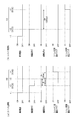
- FIG. 3 is a time chart showing power supply control.
- FIG. 4 is a circuit diagram showing the electronic control device of the second embodiment.
- FIG. 5 is a flowchart showing power supply control.
- FIG. 6 is a time chart showing power supply control.
- FIG. 7 is a flowchart showing the switch diagnosis of the third embodiment.
- FIG. 8 is a time chart showing power supply control.
- FIG. 9 is a time chart showing power supply control.
- FIG. 10 is a flowchart showing the power supply control of the fourth embodiment.
- FIG. 10 is a flowchart showing the power supply control of the fourth embodiment.
- FIG. 11 is a time chart showing power supply control.
- FIG. 12 is a circuit diagram showing the electronic control device of the fifth embodiment.
- FIG. 13 is a flowchart showing power supply control.
- FIG. 14 is a time chart showing power supply control.
- FIG. 15 is a flowchart showing the power supply control of the sixth embodiment.
- FIG. 1 is a circuit diagram showing an in-vehicle circuit of the first embodiment.
- the vehicle is equipped with the assembled battery 10 and the auxiliary battery 30, as well as a battery monitoring system 80 for monitoring the assembled battery 10.
- the assembled battery 10 is, for example, a lithium battery, and is composed of a plurality of cell batteries 15 connected in series.
- each group in which the plurality of cell batteries 15 are grouped is referred to as a “battery group 14”.
- the assembled battery 10 is connected to a load such as an inverter of a motor via a predetermined power supply path.
- Contactors 17 and 18 are provided in the power supply path. When the contactors 17 and 18 are turned on, power can be supplied from the assembled battery 10 to the load, and when the contactors 17 and 18 are turned off, power cannot be supplied from the assembled battery 10 to the load.
- the battery monitoring system 80 has a plurality of monitoring devices 20 and a battery ECU 40.
- the battery ECU 40 corresponds to the "electronic control device" referred to in the present disclosure.
- the monitoring device 20 is installed for each battery group 14, and is connected to both ends of the battery group 14 corresponding to the monitoring device 20 and between the cell batteries 15 constituting the battery group 14 by a lead wire. Then, the voltage of each cell battery 15 is detected. Further, the monitoring device 20 starts an equalization process for equalizing the voltage of each cell battery 15 based on the equalization command transmitted from the battery ECU 40.
- the auxiliary battery 30 is, for example, a lead battery, and supplies power to the battery ECU 40 and the like.
- the battery ECU 40 has a first control unit 57 and a second control unit 67.
- the electric power of the auxiliary battery 30 is supplied to the first control unit 57 from the first power supply path 51.
- a power switch 52 and a first power supply circuit 56 are provided in the first power supply path 51.
- the first power supply circuit 56 transforms a voltage of, for example, 12V supplied from the auxiliary battery 30 to, for example, 5V.
- the power switch 52 is controlled by a predetermined switch drive unit 53.
- the switch drive unit 53 controls the power switch 52 based on the connection command C transmitted from the first control unit 57 and the second control unit 67.
- connection command C when the connection command C is ON, the switch drive unit 53 turns on the power switch 52 and connects the first power supply path 51 so that it can be energized. On the other hand, when the connection command C is OFF, the switch drive unit 53 turns off the power switch 52 to disable the first power supply path 51. Therefore, in the present embodiment, the fact that the connection command C is "ON” means that the "switch command” for the power switch 52 is the “connection command”, and the connection command C is "OFF”. , Means that the "switch command” is a "cutoff command”.
- connection command C and other commands (R, D) and signals ( ⁇ , ⁇ ) described later when the command or signal is “ON”, for example, the voltage level of the command or signal is It can be a "High” level higher than a predetermined threshold. Then, when the command or signal is "OFF”, for example, the voltage level of the command or signal can be set to a "Low” level lower than a predetermined threshold value.
- the first control unit 57 is a microcomputer or the like, and is connected to each monitoring device 20 so as to be able to communicate with each other via a communication line 25.
- the first control unit 57 is activated by being supplied with power from the first power supply path 51 and is in the activated state. In the activated state, the first control unit 57 acquires cell voltage information, which is information related to the voltage of each cell battery 15, from each monitoring device 20, and transmits the above equalization command to the monitoring device 20 as necessary. ..
- the second control unit 67 When the power switch 52 of the first control unit 57 is turned from OFF to ON, the second control unit 67 first starts transmitting the connection command C to the switch drive unit 53, and the first control unit 57 is activated by the transmission of the connection command C. However, for self-holding, it also starts transmitting the connection command C to the switch drive unit 53. As a result, a redundant configuration of the connection command C is established, and it is possible to prevent the power failure of the first control unit 57 due to a failure of the connection command C of the second control unit 67.
- the first control unit 57 When turning the power switch 52 from ON to OFF, the first control unit 57 first turns off the connection command C, and then the second control unit 67 turns off the connection command C in the power switch diagnosis X3 described later. To.
- the first control unit 57 sends a predetermined start signal ⁇ as a state signal indicating whether it is in the start state or the stop state in which the start is stopped, when the first control unit 57 is in the start state. Send to. That is, in the present embodiment, when the start signal ⁇ is “ON”, it indicates that the first control unit 57 is in the “start state”, and when the start signal ⁇ is “OFF”, the first control unit 57 Indicates that is in the "stopped state”.
- the power of the auxiliary battery 30 is supplied to the second control unit 67 from the second power supply path 61, which is different from the first power supply path 51.
- a second power supply circuit 66 is provided in the second power supply path 61.
- the second power supply circuit 66 transforms a voltage of, for example, 12V supplied from the auxiliary battery 30 to, for example, 5V.
- the second control unit 67 is a microcomputer or the like different from the first control unit 57, and is completely stopped even when the main power switch (not shown) of the vehicle is turned off. Instead, keep the startup (sleep) in a power-saving state. Then, in response to the driver turning on the main power switch of the vehicle, a command from the vehicle's upper ECU (not shown), a command from an external device connected to the vehicle (not shown), etc., the sleep state is reached. Wake up from. Then, the connection command C is transmitted to the switch drive unit 53 to turn on the power switch 52 of the first control unit 57.
- the second control unit 67 performs the power switch diagnosis X3 as to whether or not the power switch 52 is abnormal based on the connection command C and the start signal ⁇ . Specifically, in the power switch diagnosis X3, an ON sticking diagnosis for determining the power switch 52 as an abnormality is performed on condition that the start signal ⁇ is OFF even though the connection command C is ON.
- FIG. 2 is a flowchart showing the power supply control including the power supply switch diagnosis X3.
- the second control unit 67 determines whether or not it is the diagnosis start timing at which the power switch diagnosis X3 should be started (S110). Specifically, for example, the timing immediately after the main power switch of the vehicle is turned from ON to OFF, that is, the timing after the contactors 17 and 18 are turned from ON to OFF at the timing when the start of the vehicle is stopped is set. It can be the diagnosis start timing. Further, for example, at the timing immediately after the main power switch of the vehicle is turned from ON to OFF, the timing after the first control unit 57 finishes storing the cell voltage information in the predetermined non-volatile memory is set as the diagnosis start timing. be able to. In this case, even if the power switch 52 is turned off in the power switch diagnosis X3, there is no possibility that the cell voltage information will be lost.
- the timing after the first control unit 57 finishes transmitting the equalization command can be set as the diagnosis start timing.
- the diagnosis start timing is the timing before the equalization process is completed, and it is preferable that the second control unit 67 performs the power switch diagnosis X3 in parallel with the execution of the equalization process. This is because the monitoring device 20 only starts the equalization process triggered by the equalization command, and after that, even if the first control unit 57 does not continue to control the monitoring device 20, the monitoring device 20 itself equalizes. Proceed with the process to complete.
- S110 If it is determined in S110 that it is not the diagnosis start timing (S110: NO), the determination in S110 is repeated. On the other hand, when it is determined in S110 that it is the diagnosis start timing (S110: YES), the connection command C is turned from ON to OFF (S120). As a result, if the power switch 52 or the like is normal, the start signal ⁇ changes from ON to OFF.
- FIG. 3A is a time chart showing the transition of each value in the power supply control when the power supply switch 52 is normal.
- the predetermined first timing t1 the power of the vehicle is turned from ON to OFF.
- the power switch diagnosis X3 is started, and the connection command C is switched from ON to OFF at a predetermined second timing t2 (S120).
- the third timing t3 after the elapse of the predetermined stop response time Sr (for example, 100 ms) from the second timing t2, the first control unit 57 stops the activation and the activation signal ⁇ changes from ON to OFF.
- FIG. 3B is a time chart showing the transition of each value in the power supply control when the power supply switch 52 is stuck ON and has a failure.
- the power of the vehicle is turned from ON to OFF.
- the power switch diagnosis X3 is started, and the connection command C is switched from ON to OFF at a predetermined second timing t2 (S120).
- the first control unit 57 continues to start, and the start signal ⁇ remains ON.
- the power switch 52 is determined to be abnormal (S150), and the abnormality confirmation flag is turned ON.
- the following effects can be obtained. If the start signal ⁇ is ON even though the connection command C is OFF, there is a high possibility that the power switch 52 is stuck ON and has a failure. In that respect, in the present embodiment, the power switch 52 is determined to be abnormal (S150) on condition that the start signal ⁇ is ON (S130: YES) when the connection command C is OFF (S120). Therefore, when the power switch 52 has an ON sticking failure, the abnormality can be detected.
- the driver is notified of the abnormality
- the first power supply path 51 is shut off by a shutoff means other than the power switch 52, or the first control unit 57 is stopped by a stop means other than the power switch 52.
- the abnormality can be dealt with. Therefore, when the power switch 52 is stuck ON and fails, it becomes easy to prevent the dark current from continuing to flow in the first control unit 57.
- the battery monitoring system 80 is a second control unit that maintains (sleeps) startup in a power saving state so that the power switch 52 of the first control unit 57 can be turned on as needed even when the main power is off.
- the power switch diagnosis X3 is carried out by using the second control unit 67. Therefore, in order to carry out the power switch diagnosis X3, it is not necessary to newly add hardware such as another microcomputer, and it is possible to detect an abnormality of the power switch 52 only by adding software such as the power switch diagnosis X3. Can be done.
- FIG. 4 is a circuit diagram showing the battery ECU 40 of this embodiment.
- the battery ECU 40 has a stop unit 58 capable of stopping the first control unit 57.
- the stop unit 58 is controlled based on a predetermined stop command R transmitted from the second control unit 67.
- the stop unit 58 maintains the first control unit 57 in the stopped state by performing a predetermined stop drive even when the power switch 52 is in the ON state when the stop command R is ON. On the other hand, the stop unit 58 releases the stop drive when the stop command R is OFF. Therefore, in the present embodiment, the fact that the stop command R is "ON” means that the “stop command” for the stop 58 is a “stop command” that commands the stop drive to be performed, and the stop command R is ". "OFF” means that the "stop command” is a "release command” that commands the release of the stop drive.
- the stop command R is normally OFF, and is turned ON on condition that the power switch 52 is determined to be abnormal in the power switch diagnosis X3.
- the power switch abnormality handling Y3 that keeps the stop command R ON while the main power is OFF is started.
- FIG. 5 is a flowchart showing the power supply control of the present embodiment. This flowchart differs from the flowchart of the first embodiment (FIG. 2) in that it has S160. That is, when the power switch 52 is determined to be abnormal in the power switch diagnosis X3 (S150), the stop command R is turned ON (S160). As a result, the first control unit 57 is put into a stopped state by the stop drive of the stop unit 58, and the power switch abnormality handling Y3 is started.
- FIG. 6A is a time chart showing the transition of each value in the power supply control when the power supply switch 52 is normal.
- the stop command R is turned OFF when the abnormality confirmation flag is turned OFF, and is turned ON when the abnormality confirmation flag is turned ON. Therefore, when the power switch 52 is normal in this way, the abnormality confirmation flag remains OFF, so that the stop command R also remains OFF.
- FIG. 6B is a time chart showing the transition of each value in the power supply control when the power supply switch 52 is stuck ON and has a failure.
- the stop command R also changes from OFF to ON (S160) in conjunction with the abnormality confirmation flag changing from OFF to ON (S150) at a predetermined timing tf.
- the first control unit 57 is stopped by the stop unit 58 and is in the stopped state.
- the start signal ⁇ is changed from ON to OFF, and the power switch abnormality handling Y3 is started.
- the second control unit 67 gives a stop command during the main power OFF state on condition that the power switch 52 is determined to be abnormal (ON stuck) in the power switch diagnosis X3 (S150: YES). Take Y3 to deal with the abnormality of the power switch that keeps R ON (S160). Therefore, it is possible to prevent the dark current from continuing to flow in the first control unit 57 due to the ON sticking failure of the power switch 52.
- FIG. 7 is a flowchart showing the power supply control of the present embodiment. Compared with the flowchart (FIG. 6) of the second embodiment, the difference is that the signal diagnosis X2 for checking whether the start signal ⁇ is normal is performed before the power switch diagnosis X3 is performed.
- the signal diagnosis X2 After the diagnosis start timing is determined in S110 (S110: YES), whether or not the start signal ⁇ is ON while the connection command C is ON and the stop command R is OFF, that is, It is determined whether it is normal or not (S111). When it is determined that the start signal ⁇ is OFF (S111: NO), the stop function is ON-fixed failure, or the start signal ⁇ is OFF-fixed failure. Therefore, it cannot be determined that the start signal ⁇ is normal, and it is determined that the stop function or the start signal ⁇ is abnormal (S114). Therefore, the connection command C is turned off (S124) without performing the power switch diagnosis X3 as it is, and the power control is terminated.
- the stop command R is changed from OFF to ON (S112).
- the first control unit 57 stops the start, and the start signal ⁇ transitions from ON to OFF. In that state, it is determined whether or not the start signal ⁇ is OFF, that is, whether or not it is normal (S113).
- S113 When it is determined that the start signal ⁇ is ON (S113: NO), there is a high possibility that the stop function has an OFF sticking failure or the start signal ⁇ has an ON sticking failure.
- the connection command C is turned from ON to OFF (S120), and then the stop command R is turned from ON to OFF (S125).
- the connection command C is turned off first. Therefore, even if the stop command R is turned off, the first control unit 57 does not start and the start signal ⁇ remains OFF. .. In that state, it is determined whether or not the start signal ⁇ is ON, that is, whether or not it is abnormal (S130). When the start signal ⁇ is determined to be OFF (S130: NO), the power switch 52 is determined to be normal (S140), and the power control is terminated.
- FIG. 8 is a time chart showing the transition of each value in the power supply control when the start signal ⁇ is stuck ON and fails.
- the power of the vehicle is turned from ON to OFF.
- the signal diagnosis X2 is started, and the stop command R is switched from OFF to ON at a predetermined second timing T2 (S112).
- the activation of the first control unit 57 is stopped by the stop unit 58.
- the start signal ⁇ is stuck to ON and has a failure, the start signal ⁇ remains ON.
- the stop function is based on the fact that the start signal ⁇ remains ON and does not change to OFF (S113: NO). Alternatively, the start signal ⁇ is determined to be abnormal (S114), and the signal or other abnormality confirmation flag is turned ON.
- the stop command R is returned from ON to OFF and the connection command C is switched from ON to OFF without performing the power switch diagnosis X3 (S124).
- FIG. 9A is a time chart showing the transition of each value in the power supply control when both the stop function and the start signal ⁇ are normal and the power supply switch 52 is normal.
- the predetermined first timing T1 the power of the vehicle is turned from ON to OFF.
- the signal diagnosis X2 is started, and the stop command R is switched from OFF to ON at a predetermined second timing T2 (S112).
- the activation of the first control unit 57 is stopped by the stop unit 58, and the activation signal ⁇ transitions from ON to OFF after a slight stop response time sr (for example, less than 1 ms) elapses from the second timing T2.
- a slight stop response time sr for example, less than 1 ms
- the power switch diagnosis X3 is started, and at the predetermined fourth timing T4, the connection command C is switched from ON to OFF (S120), and the stop command R is switched from ON to OFF (S125).
- the power switch 52 since the power switch 52 is normal, it is turned off by switching the connection command C to OFF. Therefore, even if the stop command R is switched to OFF, the first control unit 57 does not start, and the start signal ⁇ remains OFF. Then, based on the fact that the start signal ⁇ remains OFF and does not transition to ON at a predetermined timing Tn after a predetermined start wait time Aw (for example, 10 ms) has elapsed from the fourth timing T4 (S130: NO), the power switch is used. 52 is determined to be normal (S140), and the switch normal confirmation flag is turned ON.
- FIG. 9B is a time chart showing the transition of each value in the power supply control when both the stop function and the start signal ⁇ are normal and the power supply switch 52 is stuck ON.
- the procedure up to the third timing T3 is the same as in the case of FIG. 9 (a) above.
- the power switch diagnosis X3 is started, and at the predetermined fourth timing T4, the connection command C is switched from ON to OFF (S120), and the stop command R is switched from ON to OFF (S125). ).
- the power switch 52 since the power switch 52 is stuck in ON and has a failure, it remains ON even if the connection command C is switched to OFF. Therefore, when the stop command R is switched to OFF, the first control unit 57 is activated, and the activation signal ⁇ transitions from OFF to ON.
- the power supply was supplied.
- the switch 52 is determined to be abnormal (S150), and the switch abnormality confirmation flag changes from OFF to ON.
- the stop command R changes from OFF to ON, and the start of the first control unit 57 is stopped by the stop unit 58 (S160).
- the start signal ⁇ transitions from ON to OFF, and the power switch abnormality handling Y3 is started.
- the following effects can be obtained.
- the connection command C is ON and the stop command R is OFF but the start signal ⁇ is OFF instead of ON
- the stop function is ON-fixed failure or the start signal ⁇ is OFF-fixed failure.
- the signal diagnosis X2 when the connection command C is ON and the stop command R is OFF, the start signal ⁇ is ON (S111: NO), and the start signal ⁇ is normal. (S115). Therefore, when there is a possibility that the start signal ⁇ is fixed to OFF and has a failure, the start signal ⁇ cannot be determined to be normal.
- the start signal ⁇ is normally set under one of the conditions that the start signal ⁇ is OFF (S113: NO) when the stop command R is ON while the connection command C is ON. (S115). Therefore, when there is a possibility that the start-up signal ⁇ is stuck ON and has a failure, the start-up signal ⁇ cannot be determined to be normal.
- the power switch diagnosis X3 is performed on the condition that the start signal ⁇ is determined to be normal (S115), that is, the power switch 52 can be determined to be abnormal (S150). Therefore, when the start signal ⁇ cannot be determined to be normal (S114), the power switch 52 is not determined to be abnormal (S150). Therefore, it is possible to avoid erroneously determining the power switch 52 as an abnormality due to an abnormality in the start signal ⁇ .
- the power switch diagnosis X3 from the state in which the stop command R is turned ON and the stop drive is performed by the signal diagnosis X2, the connection command C is turned OFF (S120), the stop command R is turned OFF (S125), and then.
- the power switch 52 is determined to be abnormal (S150) on condition that the start signal ⁇ is turned on (S130: YES). Therefore, the power switch diagnosis X3 can be smoothly started from the state in which the stop command R after the signal diagnosis X2 is performed is ON.
- FIG. 10 is a flowchart showing the power supply control of the present embodiment. This embodiment is different from the third embodiment (FIG. 7) in that the power switch diagnosis X3 has S123 and S131 to S134. Specifically, it is as follows.
- the process proceeds to S123.
- a predetermined voltage drop waiting time Vw it is determined whether or not a predetermined voltage drop waiting time Vw has elapsed since the connection command C was turned from ON to OFF.
- the voltage drop waiting time Vw prevents the first control unit 57 from starting even if the stop command R is turned off after the connection command C is turned off when the power switch 52 is not stuck ON. It is more than the time until.
- S123 If it is determined in S123 that the voltage drop waiting time Vw has not elapsed (S123: NO), S123 is repeated. On the other hand, when it is determined in S123 that the voltage drop waiting time Vw has elapsed (S123: YES), the process proceeds to the next S125. S125 and S130 are the same as those in the third embodiment. Therefore, in S130, it is determined whether or not the start-up signal ⁇ is ON, that is, whether or not it is abnormal, in a state where the start-up signal ⁇ should be turned off.
- the process proceeds to S131 without immediately determining that the start signal ⁇ is normal.
- the predetermined start-up waiting time Aw is a time equal to or longer than the time from when the stop command R is turned off to release the stop drive and when the start-up signal ⁇ is turned on when the power switch 52 is stuck in ON. ..
- the process proceeds to S132.
- the abnormality counter is turned up. Specifically, the initial value of the abnormality counter is "0". For example, when the abnormality counter is "0", this is set to "1". For example, when the abnormality counter is "1", this is set to "2". To.
- a predetermined threshold value for example, “3”.
- the stop command R is returned from OFF to ON (S134), and then returns to S125.
- the process proceeds to S150 and the power switch 52 is determined to be abnormal. After that, it is the same as that of the third embodiment.
- FIG. 11A is a time chart showing the transition of each value in the power supply control when the stop function and the start signal ⁇ are normal and the power supply switch 52 is normal.
- the procedure up to the fourth timing T4 is the same as that of the third embodiment (FIG. 9A).
- the stop command R is switched from ON to OFF at the fifth timing T5 after the above-mentioned voltage drop waiting time Vw (for example, 100 ms) has elapsed. (S125).
- Vw voltage drop waiting time
- the voltage applied to the first control unit 57 has already dropped sufficiently. Therefore, even if the stop command R is turned off and the stop drive is released in this way, the first control unit 57 does not start.
- the power switch is used.
- the switch normal confirmation flag is turned ON.
- FIG. 11B is a time chart showing the transition of each value in the power supply control when the stop function and the start signal ⁇ are normal and the power supply switch 52 is stuck ON.
- the procedure up to the fifth timing T5 is the same as in FIG. 11 (a) above.
- the stop command R is switched from ON to OFF (S125).
- the first operation response time Ar (for example, less than 1 ms) elapses from the fifth timing T5. 1
- the control unit 57 is activated and the start signal ⁇ is changed from OFF to ON.
- the abnormality counter was set to "0". Becomes "1" (S132). Then, when the stop command R is returned from OFF to ON (S134), the first control unit 57 stops starting and the starting signal ⁇ returns from ON to OFF.
- the abnormality counter changes from "1" to "2" (S132).
- the abnormality counter changes from "2" to "3" by repeating the same operation as the eighth timing T8 (S132). As a result, the abnormality counter reaches the threshold value. As a result, the power switch 52 is determined to be abnormal (S150), and the switch abnormality confirmation flag changes from OFF to ON. As a result, the stop command R is switched from OFF to ON (S160). As a result, the first control unit 57 stops starting, the starting signal ⁇ changes from ON to OFF, and the power switch abnormality handling Y3 is started.
- the following effects can be obtained. If the voltage applied to the first control unit 57 does not drop immediately even if the power switch 52 is turned off (S120), the stop command R is turned off before the voltage drops (S125) to release the stop drive. 1 The control unit 57 is activated and the start signal ⁇ is turned ON (S130: YES). If the power switch 52 is determined to be abnormal (ON fixed) based on this (S150), even if the power switch 52 is normal, it is erroneously determined to be abnormal.
- the stop command R is turned off (S125) and the stop drive is performed. Is released, and the power switch 52 is determined to be abnormal (S150) on condition that the start signal ⁇ is turned ON (S130: YES).
- the voltage drop waiting time Vw starts the first control unit 57 even if the stop command R is turned off from (S120) when the connection command C is turned off when the power switch 52 is not stuck ON. It is more than the time until nothing happens.
- the first control unit 57 does not start immediately. If it is determined (S140) that the power switch 52 is normal (no ON sticking) based on the fact that the start signal ⁇ is OFF (S130: NO) before the start-up, the power switch 52 has an ON sticking failure. Will be erroneously determined to be normal.
- the start signal ⁇ is turned ON before the predetermined start waiting time Aw elapses (S131: NO) after the stop command R is turned OFF (S125) and the stop drive is released.
- the power switch 52 is determined to be abnormal (S150).
- the start waiting time Aw is equal to or longer than the time from when the stop command R is turned off (S125) to when the stop drive is released and when the start signal ⁇ is turned on when the power switch 52 is stuck ON. It's time.
- the following effects can be obtained.
- the start confirmation time Ac from when the start signal ⁇ is turned ON to when it is confirmed that the start signal ⁇ is turned ON (S130: YES) is lengthened, the ON sticking failure occurs during that time.
- the first control unit 57 activated by the above may start an unintended operation.
- the start confirmation time Ac is shortened, it is erroneously determined that the first control unit 57 has started even though it has not actually started due to noise or the like, and the power switch 52 is erroneously determined as abnormal in the power switch diagnosis X3. (S150) The risk increases.
- the stop command R is turned OFF (S125) from the state where the stop command R is ON (S112, S134).
- the power switch 52 is turned on on the condition that the stop drive is released and then the start signal ⁇ is turned ON (S130: YES) as a set of 1 and the set is repeated a plurality of times (S133: YES). It is determined to be abnormal (S150). Therefore, even if the start confirmation time Ac in each set is shortened, the accuracy of the power switch diagnosis X3 can be ensured by repeating the set a plurality of times. Therefore, it is possible to suppress the risk that the first control unit 57 starts an unintended operation while ensuring the accuracy of the power switch diagnosis X3.
- FIG. 12 is a circuit diagram showing the battery ECU 40 of this embodiment.
- the battery ECU 40 further includes a third power supply path 71, a power supply switch 72 and a third power supply circuit 76 provided in the third power supply path 71, and a switch drive unit 73 for driving the power supply switch 72.
- the third power supply path 71 supplies power to the auxiliary battery 30 to predetermined portions of the first control unit 57 and the second control unit 67.
- the power supply switch 72 is controlled by a predetermined switch drive unit 73.
- the switch drive unit 73 controls the power supply switch 72 based on the power supply command D transmitted from the first control unit 57 or the second control unit 67.
- the switch drive unit 73 turns on the power supply switch 72 and connects the third power supply path 71 so that the power supply path 71 can be energized when the power supply command D is ON.
- the switch drive unit 73 turns off the power supply switch 72 to disable the third power supply path 71. Therefore, in the present embodiment, the fact that the power supply command D is "ON” means that the "power supply switch command” for the power supply switch 72 is the "power supply command”, and the power supply command D is "OFF". However, it means that the "power supply switch command” is a "disconnection command".
- the power supply command D is transmitted from both the first control unit 57 and the second control unit 67 to the switch drive unit 73, so that the redundant configuration of the power supply command D is established. ..
- the first control unit 57 first turns off the power supply command D, and then the second control unit 67 in the power supply switch diagnosis X1 described later. Turn off the power supply command D.
- the third power supply circuit 76 is, for example, a reference voltage circuit, and the power supply voltage of, for example, about 12 V supplied from the auxiliary battery 30 is made substantially constant regardless of variations in the voltage of the auxiliary battery 30, temperature, and the like. Transform to 5V with high accuracy, for example. Therefore, the portion to which the power for starting the first control unit 57 and the second control unit 67 is supplied is supplied from the first power supply path 51, while the first control unit 57 and the second control unit 67 are supplied with power. A portion where high voltage accuracy is required (for example, a reference voltage input port) is wired so that power is supplied from the third power supply path 71.
- the power supply command D is turned on only when the connection command C is turned on. Therefore, when the power supply switch 52 and the power supply switch 72 are normal, only the power supply switch 72 of the power supply switch 52 and the power supply switch 72 is not turned on. Therefore, in the normal state, power is not supplied from the third power supply path 71 only to a predetermined portion of the first control unit 57.
- the third power supply circuit 76 uses a predetermined output signal ⁇ as a power supply state signal indicating whether or not a predetermined voltage is output from the third power supply path 71 in the above output state. It transmits to the first control unit 57 and the second control unit 67. That is, in the present embodiment, when the output signal ⁇ is “ON”, it indicates that it is in the above “output state”, and when the output signal ⁇ is “OFF”, it is not in the above output state “non-output”. Indicates that it is a "state”.
- the third power supply circuit 76 performs self-diagnosis, and when the voltage output by itself is equal to or higher than the above-mentioned predetermined voltage, the output signal ⁇ is turned ON, and the voltage output by itself is the above-mentioned predetermined voltage. If it is less than the voltage, the output signal ⁇ is turned off.
- the second control unit 67 Before performing the signal diagnosis X2 and the power switch diagnosis X3, the second control unit 67 performs the power supply switch diagnosis X1 based on the power supply command D and the output signal ⁇ to determine whether or not the power supply switch 72 has an ON sticking failure. ..
- FIG. 13 is a flowchart showing the power supply control of the present embodiment. Compared with the fourth embodiment (FIG. 9), the difference is that the power supply switch diagnosis X1 is performed before the signal diagnosis X2 is performed, that is, between S110 and S111.
- the power supply command D is turned from ON to OFF (S1102).
- the power supply switch 72 or the like is normal, the power supply switch 72 is turned from ON to OFF, and the output signal ⁇ is changed from ON to OFF. In that state, it is determined whether or not the output signal ⁇ is OFF, that is, whether or not it is normal (S1103).
- the power supply switch 72 is determined to be an ON sticking failure (S1105). Therefore, the power switch diagnosis X3 is not performed, and the stop command R is changed from OFF to ON while the connection command C is maintained in the ON state. As a result, the power supply switch abnormality handling Y1 that keeps the connection command C ON and the stop command R ON while the main power supply is OFF is started. Then, the power supply control is terminated.
- the power supply switch diagnosis X1 determines that the power supply switch 72 is an ON sticking failure (S1105)
- both the signal diagnosis X2 and the power switch diagnosis X3 are skipped.
- the signal diagnosis X2 is not used in the power switch diagnosis X3, but may be performed for the purpose of confirming the normality of the stop function and the start signal ⁇ . Further, for the same purpose, the signal diagnosis X2 may be performed separately from the main power supply control.
- the output signal ⁇ is determined to be OFF on the condition that the output signal ⁇ is confirmed to be OFF at two predetermined timings (S1103: YES). Further, in S1103, the output signal ⁇ is determined to be ON on condition that the output signal ⁇ remains ON during the predetermined stop waiting time SW (S1103: YES).
- FIG. 14A is a time chart showing the transition of each value in the power supply control when the power supply switch 72 is normal.
- the power of the vehicle is turned from ON to OFF.
- the power supply switch diagnosis X1 is started, and the power supply command D is switched from ON to OFF at a predetermined timing Tp (S1102). From there, the abnormal timer indicating the elapsed time starts increasing.
- the power supply switch 72 is changed from ON to OFF, and the output signal ⁇ is changed from ON to OFF.
- the abnormal timer is reset to "0"
- the normal counter is counted up from "0" to "1”.
- the normal counter is set to "1" based on the fact that the output signal ⁇ remains OFF and does not turn ON from the timing Tq when the output signal ⁇ is turned OFF to the predetermined timing Tr after the lapse of the predetermined stop confirmation time SC. Is counted up to "2".
- the normal counter reaches the threshold value.
- the power supply switch 72 is determined to be normal (S1104), and the normal confirmation flag is turned ON.
- stop function or the start signal ⁇ when the stop function or the start signal ⁇ is abnormal, it is the same as the second timing T2 or later in FIG. 8 of the third embodiment.
- stop function and the start signal ⁇ are normal and the power switch 52 is normal, it is the same as the second timing T2 and later in FIG. 11A of the fourth embodiment.
- stop function and the start signal ⁇ are normal and the power switch 52 is abnormal, it is the same as the second timing T2 and later in FIG. 11B of the fourth embodiment.
- FIG. 14B is a time chart showing the transition of each value in the power supply control when the power supply switch 72 is stuck ON and fails. The procedure is the same as in FIG. 14 (a) up to the predetermined timing Tp. At the predetermined timing Tp, the power supply command D is switched from ON to OFF (S1102), and from there, the abnormal timer indicating the elapsed time starts to increase.
- the power supply switch 72 since the power supply switch 72 has an ON sticking failure, even if the power supply command D is switched to OFF, it does not turn OFF and remains ON. Therefore, the output signal ⁇ also remains ON. As a result, the abnormal timer increases without being reset. Then, when the abnormal timer reaches the threshold value at the predetermined timing Ts after the predetermined stop waiting time SW elapses from the timing Tp when the power supply command D is turned off, the power supply switch 72 is determined to be an ON sticking failure (S1105). The abnormality confirmation flag of the power supply switch 72 is turned ON. As a result, at a predetermined timing Tf thereafter, the stop command R is switched from OFF to ON (S160), and the power supply switch abnormality handling Y1 is started.
- the following effects can be obtained. If the power supply switch 52 is turned off in a state where the power supply switch 72 has an ON sticking failure, power is supplied only to a predetermined portion of the first control unit 57 due to the ON sticking failure of the power supply switch 72. As a result, the first control unit 57 may have a predetermined defect such as withstand voltage failure.
- connection command C is kept ON and the stop command R is turned ON while the main power supply is OFF.
- the power supply switch abnormality countermeasure Y1 is performed (S160). Therefore, by keeping the connection command C ON in this way, it is possible to avoid supplying power only to a predetermined portion of the first control unit 57. Further, by keeping the stop command R ON in this way, it is possible to keep the first control unit 57 in the stopped state and avoid a dark current flowing through the first control unit 57.
- the power supply switch 72 is stuck ON, even if the power supply switch 52 is abnormal, it is necessary to execute a process such as the power supply switch abnormality handling Y1 instead of the power supply switch abnormality handling Y3. Therefore, it is useless to determine whether or not the power switch 52 is abnormal.
- the power supply switch diagnosis X1 determines that the power supply switch 72 is not stuck ON and has not failed
- the power supply switch diagnosis X3 is performed to determine whether or not the power supply switch 52 is abnormal. .. Therefore, when the power supply switch 72 is determined to be an ON sticking failure, it is not determined whether or not the power supply switch 52 is abnormal. Therefore, when the power supply switch 72 is stuck ON and the power supply switch 52 is abnormal or not, and the power supply switch abnormality countermeasure Y1 is executed, the waste of determining whether the power supply switch 52 is abnormal or not is eliminated. Can be done.
- the power supply switch 72 is determined to be an ON sticking failure on condition that the output signal ⁇ is ON (S1103: NO) when the power supply command D is OFF (S1102) (S1105). Therefore, the ON sticking failure of the power supply switch 72 can be found by a simple method.
- FIG. 15 is a flowchart showing the power supply control of the present embodiment. It differs from the first embodiment (FIG. 2) in that S117 is provided between S110 and S120. Specifically, when it is determined in S110 that the diagnosis start timing is reached, the process proceeds to S117, and in the state where the connection command C is ON, it is determined whether or not the start signal ⁇ is ON, that is, whether or not it is normal. When it is determined that the start signal ⁇ is OFF (S117: NO), there is a high possibility that the power switch 52 has an OFF sticking failure, so the process proceeds to S150 and the power switch 52 is determined to be abnormal. On the other hand, if it is determined in S117 that the start signal ⁇ is ON, the process proceeds to S120. The procedure after S120 is the same as that of the first embodiment.
- the power switch 52 can be determined to be abnormal not only when the power switch 52 has an ON sticking failure but also when the power switch 52 has an OFF sticking failure. Therefore, in the present embodiment, both the ON sticking diagnosis and the OFF sticking diagnosis can be performed.
- the configuration of the battery ECU 40 of each embodiment may be adopted for an electronic control device for a vehicle other than the battery ECU 40. Further, for example, instead of both the first control unit 57 and the second control unit 67 transmitting the connection command C to the switch drive unit 53, only the second control unit 67 sends the connection command C to the switch drive unit 53. You may send it.
- a cutoff command for commanding the OFF of the power switch 52 is transmitted instead of the connection command C for commanding the ON of the power switch 52. You may. And, when the cutoff command is "OFF”, it means that the "switch command” is the "connection command”, and when the cutoff command is "ON”, the "switch command” is the “cutoff command”. It may mean that there is.
- the voltage level of the command or signal is "High” level instead of the voltage level of the command or signal being "High” level.
- “Low” level may be repeated alternately. That is, the command or signal may be a pulse or the like.
- each embodiment instead of performing the power control of each embodiment at each timing when the main power switch of the vehicle is turned from ON to OFF, every time the main power switch is turned from ON to OFF.
- the power supply control of each embodiment may be performed every one of the timings of the above, and only the signal diagnosis X2 may be performed every other time.
- the power switch diagnosis X3 is performed and then the signal diagnosis X2 is performed. You may.
- the signal diagnosis X2 can be performed on the condition that the power switch 52 is tentatively determined to be abnormal in the power switch diagnosis X3. Then, for example, when the start signal ⁇ cannot be determined to be normal in the signal diagnosis X2, it is possible to prevent the power switch diagnosis X3 from making the main determination that the power switch 52 is abnormal.
- the voltage drop waiting time Vw in the fourth embodiment is, for example, 100 ms, but of course, this may be changed.
- the voltage drop waiting time Vw is preferably 1 ms or more from the shortest response (voltage drop) estimate, more preferably 30 ms or more from the longest response (voltage drop) estimate, and other uncertainties. Considering the factors, it is more preferably 100 ms or more.
- the voltage drop waiting time Vw is preferably not too long (for example, 1000 ms or less) so that the power switch diagnosis X3 can be performed quickly.
- the start-up waiting time Aw in the fourth embodiment is, for example, 50 ms, but of course, this may be changed.
- the activation waiting time Aw is preferably 1 ms or more from the estimated minimum time that can be responded (activated), more preferably 20 ms or more from the estimated maximum time that can be responded, and other uncertain factors. In consideration, it is more preferably 50 ms or more.
- the start-up waiting time Aw is preferably not too long (for example, 1000 ms or less) so that the power switch diagnosis X3 can be performed quickly.
Landscapes
- Engineering & Computer Science (AREA)
- Power Engineering (AREA)
- Mechanical Engineering (AREA)
- Transportation (AREA)
- Life Sciences & Earth Sciences (AREA)
- Sustainable Development (AREA)
- Sustainable Energy (AREA)
- Manufacturing & Machinery (AREA)
- Automation & Control Theory (AREA)
- Chemical & Material Sciences (AREA)
- Chemical Kinetics & Catalysis (AREA)
- Electrochemistry (AREA)
- General Chemical & Material Sciences (AREA)
- Electric Propulsion And Braking For Vehicles (AREA)
- Charge And Discharge Circuits For Batteries Or The Like (AREA)
- Direct Current Feeding And Distribution (AREA)
- Secondary Cells (AREA)
- Keying Circuit Devices (AREA)
Priority Applications (2)
| Application Number | Priority Date | Filing Date | Title |
|---|---|---|---|
| CN202080067370.0A CN114450197B (zh) | 2019-09-27 | 2020-09-25 | 电子控制装置 |
| US17/705,883 US11897342B2 (en) | 2019-09-27 | 2022-03-28 | Electronic control apparatus |
Applications Claiming Priority (2)
| Application Number | Priority Date | Filing Date | Title |
|---|---|---|---|
| JP2019-176630 | 2019-09-27 | ||
| JP2019176630A JP7063312B2 (ja) | 2019-09-27 | 2019-09-27 | 電子制御装置 |
Related Child Applications (1)
| Application Number | Title | Priority Date | Filing Date |
|---|---|---|---|
| US17/705,883 Continuation US11897342B2 (en) | 2019-09-27 | 2022-03-28 | Electronic control apparatus |
Publications (1)
| Publication Number | Publication Date |
|---|---|
| WO2021060546A1 true WO2021060546A1 (ja) | 2021-04-01 |
Family
ID=75164997
Family Applications (1)
| Application Number | Title | Priority Date | Filing Date |
|---|---|---|---|
| PCT/JP2020/036483 Ceased WO2021060546A1 (ja) | 2019-09-27 | 2020-09-25 | 電子制御装置 |
Country Status (4)
| Country | Link |
|---|---|
| US (1) | US11897342B2 (https=) |
| JP (1) | JP7063312B2 (https=) |
| CN (1) | CN114450197B (https=) |
| WO (1) | WO2021060546A1 (https=) |
Families Citing this family (3)
| Publication number | Priority date | Publication date | Assignee | Title |
|---|---|---|---|---|
| US12212163B2 (en) * | 2019-07-25 | 2025-01-28 | Samsung Sdi Co., Ltd. | Battery system |
| CN116260218A (zh) * | 2023-02-28 | 2023-06-13 | 华为数字能源技术有限公司 | 一种功率变换装置及储能装置 |
| CN119659330B (zh) * | 2025-01-20 | 2025-11-04 | 奇瑞新能源汽车股份有限公司 | 车辆电池的控制方法、装置 |
Citations (4)
| Publication number | Priority date | Publication date | Assignee | Title |
|---|---|---|---|---|
| JP2009038857A (ja) * | 2007-07-31 | 2009-02-19 | Yazaki Corp | 電圧調整装置 |
| JP2015058885A (ja) * | 2013-09-20 | 2015-03-30 | 日立オートモティブシステムズ株式会社 | 自動車用電子制御装置 |
| JP2015211557A (ja) * | 2014-04-25 | 2015-11-24 | トヨタ自動車株式会社 | 蓄電システム |
| WO2015194407A1 (ja) * | 2014-06-18 | 2015-12-23 | 日立オートモティブシステムズ株式会社 | 車載制御装置または車載制御システム |
Family Cites Families (14)
| Publication number | Priority date | Publication date | Assignee | Title |
|---|---|---|---|---|
| GB2435939A (en) * | 2006-01-23 | 2007-09-12 | John Phillip Chevalier | Electronic control system for safety or security critical devices or systems in a vehicle |
| JP5931694B2 (ja) * | 2012-10-29 | 2016-06-08 | 富士通テン株式会社 | 制御システム |
| JP5449593B1 (ja) * | 2013-03-05 | 2014-03-19 | 三菱電機株式会社 | 車載電子制御装置及びその給電制御方法 |
| JP5907118B2 (ja) * | 2013-05-22 | 2016-04-20 | 株式会社デンソー | 電源システム異常検出装置 |
| JP2015058846A (ja) * | 2013-09-19 | 2015-03-30 | 株式会社オートネットワーク技術研究所 | 診断システム |
| US10361467B2 (en) * | 2014-09-26 | 2019-07-23 | Panasonic Intellectual Property Management Co., Ltd. | Power supply device |
| JP6417249B2 (ja) * | 2015-03-17 | 2018-10-31 | 日立オートモティブシステムズ株式会社 | 車両用制御装置及び車両用制御システム |
| JP7024226B2 (ja) | 2016-07-11 | 2022-02-24 | 株式会社デンソー | モータ制御装置、モータ駆動システム、及び、モータ制御方法 |
| WO2018012417A1 (ja) | 2016-07-11 | 2018-01-18 | 株式会社デンソー | モータ制御装置、モータ駆動システム、及び、モータ制御方法 |
| US10668945B2 (en) | 2016-07-11 | 2020-06-02 | Denso Corporation | Motor control apparatus, motor drive system, and motor control method |
| JP6665757B2 (ja) * | 2016-11-08 | 2020-03-13 | 株式会社デンソー | 電源制御装置、及び電池ユニット |
| JP6627732B2 (ja) * | 2016-12-07 | 2020-01-08 | 株式会社デンソー | 電源回路装置 |
| JP7052347B2 (ja) | 2017-02-28 | 2022-04-12 | 株式会社デンソー | モータ制御装置、モータ駆動システム、及び、モータ制御方法 |
| US10639998B2 (en) * | 2018-04-20 | 2020-05-05 | Ford Global Technologies, Llc | Service disconnect notification strategy |
-
2019
- 2019-09-27 JP JP2019176630A patent/JP7063312B2/ja active Active
-
2020
- 2020-09-25 WO PCT/JP2020/036483 patent/WO2021060546A1/ja not_active Ceased
- 2020-09-25 CN CN202080067370.0A patent/CN114450197B/zh active Active
-
2022
- 2022-03-28 US US17/705,883 patent/US11897342B2/en active Active
Patent Citations (4)
| Publication number | Priority date | Publication date | Assignee | Title |
|---|---|---|---|---|
| JP2009038857A (ja) * | 2007-07-31 | 2009-02-19 | Yazaki Corp | 電圧調整装置 |
| JP2015058885A (ja) * | 2013-09-20 | 2015-03-30 | 日立オートモティブシステムズ株式会社 | 自動車用電子制御装置 |
| JP2015211557A (ja) * | 2014-04-25 | 2015-11-24 | トヨタ自動車株式会社 | 蓄電システム |
| WO2015194407A1 (ja) * | 2014-06-18 | 2015-12-23 | 日立オートモティブシステムズ株式会社 | 車載制御装置または車載制御システム |
Also Published As
| Publication number | Publication date |
|---|---|
| JP2021057938A (ja) | 2021-04-08 |
| CN114450197B (zh) | 2024-08-16 |
| CN114450197A (zh) | 2022-05-06 |
| US20220219543A1 (en) | 2022-07-14 |
| US11897342B2 (en) | 2024-02-13 |
| JP7063312B2 (ja) | 2022-05-09 |
Similar Documents
| Publication | Publication Date | Title |
|---|---|---|
| JP4518150B2 (ja) | 車両用電子制御装置 | |
| JP6610456B2 (ja) | バックアップ電源装置およびバックアップシステム | |
| WO2021060546A1 (ja) | 電子制御装置 | |
| US9519337B2 (en) | Circuitry for controlling an output from an electronic control unit including two processors mutually monitoring each other | |
| US10911252B2 (en) | Communication system for vehicle and method for controlling the same | |
| JP2008267297A (ja) | エコラン制御装置及びエンジン再始動方法 | |
| CN105700419A (zh) | 整车控制器的控制方法、装置以及整车控制方法、系统 | |
| US20180182583A1 (en) | Load driver | |
| KR100544940B1 (ko) | 버스 방식 통신 네트워크에서의 통신 에러 검출 방법 | |
| CN107428297A (zh) | 车辆用控制装置及其控制方法 | |
| JP6323296B2 (ja) | 制御装置 | |
| JP4940681B2 (ja) | 電子制御装置 | |
| JP6458150B2 (ja) | 電子制御装置 | |
| JP2011039608A (ja) | 処理システム、動作状態制御方法及びコンピュータプログラム | |
| JP2011093389A (ja) | 制御システム、電子装置、制御装置及び装置起動方法 | |
| JP2010137612A (ja) | 車両用制御ユニットの通信システム | |
| JP4866214B2 (ja) | 制御ユニットおよび車載用の多重通信システム | |
| JP5764043B2 (ja) | 車両の制御システム | |
| CN110043404B (zh) | 燃料泵的控制装置 | |
| JP7586035B2 (ja) | 電子制御装置 | |
| JP2005020570A (ja) | 多重通信システム | |
| JP2020020478A (ja) | バックアップ電源装置およびバックアップシステム | |
| JP2008055980A (ja) | 自動車の電子制御装置 | |
| JP2009268286A (ja) | 電動車両の制御装置及び制御方法 | |
| US12430963B2 (en) | Vehicle control system and vehicle control method |
Legal Events
| Date | Code | Title | Description |
|---|---|---|---|
| 121 | Ep: the epo has been informed by wipo that ep was designated in this application |
Ref document number: 20870430 Country of ref document: EP Kind code of ref document: A1 |
|
| NENP | Non-entry into the national phase |
Ref country code: DE |
|
| 122 | Ep: pct application non-entry in european phase |
Ref document number: 20870430 Country of ref document: EP Kind code of ref document: A1 |