WO2021060150A1 - 弾性波フィルタ - Google Patents
弾性波フィルタ Download PDFInfo
- Publication number
- WO2021060150A1 WO2021060150A1 PCT/JP2020/035303 JP2020035303W WO2021060150A1 WO 2021060150 A1 WO2021060150 A1 WO 2021060150A1 JP 2020035303 W JP2020035303 W JP 2020035303W WO 2021060150 A1 WO2021060150 A1 WO 2021060150A1
- Authority
- WO
- WIPO (PCT)
- Prior art keywords
- elastic wave
- resonator
- central region
- resonators
- sound velocity
- Prior art date
- Legal status (The legal status is an assumption and is not a legal conclusion. Google has not performed a legal analysis and makes no representation as to the accuracy of the status listed.)
- Ceased
Links
Images






Classifications
-
- H—ELECTRICITY
- H03—ELECTRONIC CIRCUITRY
- H03H—IMPEDANCE NETWORKS, e.g. RESONANT CIRCUITS; RESONATORS
- H03H9/00—Networks comprising electromechanical or electro-acoustic elements; Electromechanical resonators
- H03H9/02—Details
- H03H9/125—Driving means, e.g. electrodes, coils
- H03H9/145—Driving means, e.g. electrodes, coils for networks using surface acoustic waves
- H03H9/14538—Formation
- H03H9/14541—Multilayer finger or busbar electrode
-
- H—ELECTRICITY
- H03—ELECTRONIC CIRCUITRY
- H03H—IMPEDANCE NETWORKS, e.g. RESONANT CIRCUITS; RESONATORS
- H03H9/00—Networks comprising electromechanical or electro-acoustic elements; Electromechanical resonators
- H03H9/46—Filters
- H03H9/54—Filters comprising resonators of piezoelectric or electrostrictive material
- H03H9/56—Monolithic crystal filters
- H03H9/566—Electric coupling means therefor
- H03H9/568—Electric coupling means therefor consisting of a ladder configuration
-
- H—ELECTRICITY
- H03—ELECTRONIC CIRCUITRY
- H03H—IMPEDANCE NETWORKS, e.g. RESONANT CIRCUITS; RESONATORS
- H03H9/00—Networks comprising electromechanical or electro-acoustic elements; Electromechanical resonators
- H03H9/02—Details
- H03H9/125—Driving means, e.g. electrodes, coils
- H03H9/145—Driving means, e.g. electrodes, coils for networks using surface acoustic waves
-
- H—ELECTRICITY
- H03—ELECTRONIC CIRCUITRY
- H03H—IMPEDANCE NETWORKS, e.g. RESONANT CIRCUITS; RESONATORS
- H03H9/00—Networks comprising electromechanical or electro-acoustic elements; Electromechanical resonators
- H03H9/02—Details
- H03H9/125—Driving means, e.g. electrodes, coils
- H03H9/145—Driving means, e.g. electrodes, coils for networks using surface acoustic waves
- H03H9/14544—Transducers of particular shape or position
- H03H9/1457—Transducers having different finger widths
-
- H—ELECTRICITY
- H03—ELECTRONIC CIRCUITRY
- H03H—IMPEDANCE NETWORKS, e.g. RESONANT CIRCUITS; RESONATORS
- H03H9/00—Networks comprising electromechanical or electro-acoustic elements; Electromechanical resonators
- H03H9/02—Details
- H03H9/02228—Guided bulk acoustic wave devices or Lamb wave devices having interdigital transducers situated in parallel planes on either side of a piezoelectric layer
-
- H—ELECTRICITY
- H03—ELECTRONIC CIRCUITRY
- H03H—IMPEDANCE NETWORKS, e.g. RESONANT CIRCUITS; RESONATORS
- H03H9/00—Networks comprising electromechanical or electro-acoustic elements; Electromechanical resonators
- H03H9/02—Details
- H03H9/02535—Details of surface acoustic wave devices
- H03H9/02543—Characteristics of substrate, e.g. cutting angles
- H03H9/02574—Characteristics of substrate, e.g. cutting angles of combined substrates, multilayered substrates, piezoelectrical layers on not-piezoelectrical substrate
-
- H—ELECTRICITY
- H03—ELECTRONIC CIRCUITRY
- H03H—IMPEDANCE NETWORKS, e.g. RESONANT CIRCUITS; RESONATORS
- H03H9/00—Networks comprising electromechanical or electro-acoustic elements; Electromechanical resonators
- H03H9/02—Details
- H03H9/02535—Details of surface acoustic wave devices
- H03H9/02818—Means for compensation or elimination of undesirable effects
- H03H9/02881—Means for compensation or elimination of undesirable effects of diffraction of wave beam
-
- H—ELECTRICITY
- H03—ELECTRONIC CIRCUITRY
- H03H—IMPEDANCE NETWORKS, e.g. RESONANT CIRCUITS; RESONATORS
- H03H9/00—Networks comprising electromechanical or electro-acoustic elements; Electromechanical resonators
- H03H9/02—Details
- H03H9/125—Driving means, e.g. electrodes, coils
- H03H9/13—Driving means, e.g. electrodes, coils for networks consisting of piezoelectric or electrostrictive materials
-
- H—ELECTRICITY
- H03—ELECTRONIC CIRCUITRY
- H03H—IMPEDANCE NETWORKS, e.g. RESONANT CIRCUITS; RESONATORS
- H03H9/00—Networks comprising electromechanical or electro-acoustic elements; Electromechanical resonators
- H03H9/15—Constructional features of resonators consisting of piezoelectric or electrostrictive material
- H03H9/205—Constructional features of resonators consisting of piezoelectric or electrostrictive material having multiple resonators
-
- H—ELECTRICITY
- H03—ELECTRONIC CIRCUITRY
- H03H—IMPEDANCE NETWORKS, e.g. RESONANT CIRCUITS; RESONATORS
- H03H9/00—Networks comprising electromechanical or electro-acoustic elements; Electromechanical resonators
- H03H9/46—Filters
- H03H9/54—Filters comprising resonators of piezoelectric or electrostrictive material
-
- H—ELECTRICITY
- H03—ELECTRONIC CIRCUITRY
- H03H—IMPEDANCE NETWORKS, e.g. RESONANT CIRCUITS; RESONATORS
- H03H9/00—Networks comprising electromechanical or electro-acoustic elements; Electromechanical resonators
- H03H9/46—Filters
- H03H9/64—Filters using surface acoustic waves
-
- H—ELECTRICITY
- H03—ELECTRONIC CIRCUITRY
- H03H—IMPEDANCE NETWORKS, e.g. RESONANT CIRCUITS; RESONATORS
- H03H9/00—Networks comprising electromechanical or electro-acoustic elements; Electromechanical resonators
- H03H9/46—Filters
- H03H9/64—Filters using surface acoustic waves
- H03H9/6489—Compensation of undesirable effects
- H03H9/6496—Reducing ripple in transfer characteristic
Definitions
- the present invention relates to a band-passing type elastic wave filter having a plurality of elastic wave resonators.
- Patent Document 2 discloses a structure in which a piston mode is formed in an elastic wave resonator and the ripple in the transverse mode is suppressed. More specifically, in the IDT electrode, a region where electrode fingers connected to different potentials overlap each other in the elastic wave propagation direction is defined as a crossing region. This crossed region has a central region located at the center in a direction orthogonal to the elastic wave propagation direction, and first and second edge regions provided on both sides of the central region in a direction orthogonal to the elastic wave propagation direction. The piston mode is generated by lowering the sound velocity in the first and second edge regions to be lower than the sound velocity in the central region.
- a structure for providing the above sound velocity difference 1) a structure in which the width of the first and second edge regions is wider than the central region, or 2) a sound velocity lowering film is provided in the first and second edge regions.
- the laminated structure is disclosed.
- An object of the present invention is to provide an elastic wave filter capable of suppressing transverse mode ripple and improving the steepness of filter characteristics even when miniaturization is promoted.
- the elastic wave filter according to the present invention includes a plurality of elastic wave resonators having a piezoelectric substrate and an IDT electrode which is configured on the piezoelectric substrate and has first and second electrode fingers to be interleaved with each other.
- the crossing region In the elastic wave propagation direction, when the region where the first electrode finger and the second electrode finger overlap is defined as the crossing region, the crossing region is located at the center in the extending direction of the first and second electrode fingers. It has a central region and first and second edge regions arranged on both outer sides of the central region in the direction in which the first and second electrode fingers extend, and the first and second edge regions.
- the sound velocity in the central region is lower than the sound velocity in the central region, and the plurality of elastic wave resonators have the width of the first electrode finger and the width of the second electrode finger in the first and second edge regions.
- a plurality of elastics having a piezoelectric substrate and an IDT electrode configured on the piezoelectric substrate and having first and second electrode fingers intervening with each other.
- the crossing region is the first and second electrode fingers. It has a central region located at the center in the extending direction of the above, and first and second edge regions arranged on both outer sides of the central region in the direction in which the first and second electrode fingers extend.
- the sound velocity in the second edge region is lower than the sound velocity in the central region
- the plurality of elastic wave resonators are the width of the first electrode finger and the first electrode finger in the first and second edge regions.
- an elastic wave filter that can achieve both suppression of transverse mode ripple and improvement of steepness of filter characteristics even when miniaturization is advanced.
- FIG. 1 is a circuit diagram of an elastic wave filter according to the first embodiment of the present invention.
- FIG. 2A is a schematic plan view showing an electrode structure of an elastic wave resonator of the elastic wave filter of the first embodiment
- FIG. 2B is a front sectional view of the elastic wave resonator.
- FIG. 3 is a plan view for explaining the IDT electrode of the first elastic wave resonator.
- FIG. 4 is a plan view for explaining the electrode structure of the IDT electrode of the second elastic wave resonator.
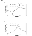
- 5 (a) is a diagram showing the resonance characteristics of the first and second elastic wave resonators
- FIG. 5 (b) is an enlarged portion of the portion shown by the circle A in FIG. 5 (a). It is a figure which shows.
- FIG. 5 (a) is a diagram showing the resonance characteristics of the first and second elastic wave resonators
- FIG. 5 (b) is an enlarged portion of the portion shown by the circle A in FIG. 5 (a). It is a
- FIG. 6 is a diagram showing the attenuation-frequency characteristics of the elastic wave filters of Example 1 and Comparative Example 1.
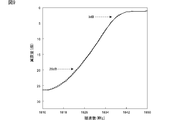
- FIG. 7 is a diagram showing the attenuation-frequency characteristics of the elastic wave filters of Example 1 and Comparative Example 1, in which the portion indicated by the arrow B in FIG. 6 is enlarged.
- FIG. 8 is a diagram showing the attenuation-frequency characteristics of the elastic wave filters of Example 2 and Comparative Example 1.
- FIG. 9 is a diagram showing the attenuation-frequency characteristics of the elastic wave filters of the second embodiment and the first comparative example, in which the portion indicated by the arrow C in FIG. 8 is enlarged.
- FIG. 10 is a circuit diagram of a duplexer having an elastic wave filter according to a second embodiment of the present invention.
- FIG. 10 is a circuit diagram of a duplexer having an elastic wave filter according to a second embodiment of the present invention.
- FIG. 11 is a circuit diagram of a duplexer having an elastic wave filter according to a third embodiment of the present invention.
- 12 (a) to 12 (d) are partial front sectional views for explaining a modified example of the electrode structure of the second elastic wave resonator.
- FIG. 13 is a plan view showing the IDT electrode of the second elastic wave resonator used in the elastic wave filter according to the fourth embodiment of the present invention.
- FIG. 1 is a circuit diagram of an elastic wave filter according to the first embodiment of the present invention.
- the elastic wave filter 1 is a ladder type filter having a plurality of elastic wave resonators.
- a plurality of series arm resonators S1, S2-1, S2-2, S3, and S4 are provided on the series arm connecting the input terminal 2 and the output terminal 3.
- a plurality of parallel arms connecting the series arms and the ground potential are provided.
- parallel arm resonators P1, P2 or P3 are provided in each of the plurality of parallel arms.
- the series arm resonators S1, S2-1, S2-2, S3, S4 and the parallel arm resonators P1 to P3 are each composed of elastic wave resonators.
- the feature of the elastic wave filter 1 is that a plurality of elastic wave resonators have the following first elastic wave resonator and second elastic wave resonator.
- the plurality of elastic wave resonators may have elastic wave resonators having a structure different from that of the first elastic wave resonator and the second elastic wave resonator.
- the first and second elastic wave resonators have a structure that forms a piston mode and suppresses ripple in the transverse mode.
- the elastic wave resonator has a piezoelectric substrate and an IDT electrode configured on the piezoelectric substrate.
- the region where the first electrode finger and the second electrode finger of the IDT electrode overlap in the elastic wave propagation direction is defined as a crossing region.
- the crossed regions are arranged on both outer sides of the central region located in the center of the extending direction of the first and second electrode fingers and the outer sides of the central region in the extending direction of the first and second electrode fingers. It has two edge regions.
- the sound velocity in the first and second edge regions is lower than the sound velocity in the central region. As a result, the piston mode is formed, and the ripple of the transverse mode is suppressed.
- the first and second elastic wave resonators have the following structure in order to realize the difference in sound velocity between the sound velocity in the central region and the sound velocity in the first and second edge regions.
- the widths of the first and second electrode fingers in the first and second edge regions are made larger than the widths of the first and second electrode fingers in the central region. That is, the first and second edge regions are widened portions.
- at least one of the width of the first electrode finger and the width of the second electrode finger in the first and second edge regions is the width of the first electrode finger and the second electrode in the central region. It suffices to be greater than at least one of the widths of the fingers.
- sound velocity reducing films are laminated on the first and second edge regions so that the sound velocity in the first and second edge regions is lower than the sound velocity in the central region. It includes at least one of the configuration and a configuration in which a sound velocity improving film for increasing the sound velocity is laminated in the central region.
- the first elastic wave resonator and the second elastic wave resonator have different configurations for realizing the difference in sound velocity between the sound velocity in the first and second edge regions and the sound velocity in the central region. ing. This will be described more specifically.
- FIG. 2A is a schematic plan view showing an electrode structure of an elastic wave resonator of the elastic wave filter of the first embodiment
- FIG. 2B is a front sectional view thereof.
- the series arm resonators S1, S2-1, S2-2, S3 and S4 and the parallel arm resonators P1, P2 and P3 all have such a structure.
- the elastic wave resonator 4 has an IDT electrode 5 and reflectors 6 and 7. As a result, a 1-port elastic wave resonator is formed.
- the IDT electrode 5 has a plurality of first electrode fingers 5a and a plurality of second electrode fingers 5b.
- a plurality of first electrode fingers 5a and a plurality of second electrode fingers 5b are interleaved with each other.
- the direction orthogonal to the extending direction of the first electrode finger 5a and the second electrode finger 5b is the elastic wave propagation direction.
- the region where the first electrode finger 5a and the second electrode finger 5b overlap when viewed in the elastic wave propagation direction is the above-mentioned crossing region.
- the piezoelectric substrate 8 is not particularly limited, but is a laminated substrate having a support substrate 8a, a high sound velocity material layer 8b, a low sound velocity film 8c, and a piezoelectric film 8d.
- the piezoelectric substrate 8 may be a single piezoelectric substrate made of LiNbO 3 or the like.
- the piezoelectric film 8d is made of LiTaO 3 .
- the support substrate 8a is made of an appropriate insulating material such as Si or alumina or a semiconductor material. In this embodiment, the support substrate 8a is made of Si.
- the hypersonic material layer 8b is made of a hypersonic material.
- the hypersonic material refers to a material in which the sound velocity of the propagating bulk wave is higher than the sound velocity of the elastic wave propagating in the piezoelectric film 8d.
- high-frequency materials include aluminum oxide, silicon carbide, silicon nitride, silicon nitride, silicon, sapphire, lithium tantalate, lithium niobate, crystal, alumina, zirconia, cozylite, mulite, steatite, and forsterite.
- Various materials such as magnesia, DLC (diamond-like carbon) film or diamond, a medium containing the above-mentioned material as a main component, and a medium containing a mixture of the above-mentioned materials as a main component can be used.
- the bass velocity film 8c is made of a bass velocity material.
- the low sound velocity material refers to a material in which the sound velocity of the propagating bulk wave is lower than the sound velocity of the bulk wave propagating in the piezoelectric film 8d.
- Examples of the low sound velocity material include silicon oxide, glass, silicon nitride, tantalum oxide, a compound obtained by adding fluorine, carbon, boron, hydrogen, or a silanol group to silicon oxide, a medium containing the above material as a main component, and the like.
- Various materials can be used.
- the Q value can be increased by using the piezoelectric substrate 8 made of the composite substrate.
- the piezoelectric substrate 8 having the hypersonic material layer 8b was used, but a support substrate made of a hypersonic material may be used instead of the hypersonic material layer 8b and the support substrate 8a. That is, the support substrate 8a and the hypersonic material layer 8b may be integrally formed of the hypersonic material.
- the bass velocity film 8c does not have to be provided. That is, the piezoelectric film 8d may be directly laminated on the hypersonic material layer 8b.
- the first elastic wave resonator and the second elastic wave resonator are used.
- the series arm resonator S3 is composed of the first elastic wave resonator.
- the remaining elastic wave resonators that is, the series arm resonators S1, S2-1, S2-2, S4 and the parallel arm resonators P1 to P3 are composed of the second elastic wave resonators.
- the following elastic wave resonators were prepared as the first elastic wave resonators.
- the IDT electrode 5 and the reflectors 6 and 7 have Al as the main electrode layer.
- the thickness of the Al film was 145 nm.
- the electrode structure 11 of the IDT electrode in the first elastic wave resonator is shown in a plan view in FIG.
- the crossing region D has a central region F and first and second edge regions E1 and E2.
- the first electrode finger 5a and the second electrode finger 5b are widened portions 5a1, 5a2, 5b1, 5b2 in the first and second edge regions E1 and E2.
- the width of the widening portion 5a1, 5a2, 5b1, 5b2 is made thicker than the width in the central region F.
- the width refers to the dimensions of the first and second electrode fingers 5a and 5b along the elastic wave propagation direction.
- the wavelength ⁇ determined by the electrode finger pitch in the central region of the IDT electrode was set to 2 ⁇ m.
- the duty in the central region was set to 0.45.
- the duty in the first and second edge regions was set to 0.73.
- the duty of the central region F is 0.45, and in the second elastic wave resonator, the duty of the central region F is 0.5.
- the capacitance of the first elastic wave resonator and the second elastic wave resonator are adjusted by reducing the crossing width.
- FIG. 4 is a plan view for explaining the electrode structure 21 of the IDT electrode of the second elastic wave resonator.
- the second elastic wave resonator was configured in the same manner except that the electrode structure of the IDT electrode was different from that of the first elastic wave resonator.
- the sound velocity lowering films 22b and 22a are laminated in the first and second edge regions E1 and E2.
- the sound velocity reducing films 22b and 22a are provided so as to extend along the elastic wave propagation direction in the first and second edge regions E1 and E2.
- the sound velocity reducing films 22a and 22b here are made of tantalum pentoxide.
- the sound velocity reducing films 22a and 22b may be made of other insulating materials as long as the mass is added and the sound velocity is reduced. Further, the sound velocity lowering films 22a and 22b may be made of metal or the like if they are provided so as not to short-circuit the first and second electrode fingers 5a and 5b.
- the wavelength of the IDT electrode was set to 2 ⁇ m, and the duty in the central region and the first and second edge regions was set to 0.50.
- the resonance characteristics of the first elastic wave resonator and the second elastic wave resonator will be described with reference to FIGS. 5 (a) and 5 (b).
- FIG. 5A shows the resonance characteristic of the first elastic wave resonator
- the broken line shows the resonance characteristic of the second elastic wave resonator.
- FIG. 5 (b) is an enlarged view showing a portion indicated by a circle A in FIG. 5 (a).
- the second elastic wave resonator Compared with the first elastic wave resonator, in the second elastic wave resonator, it is not necessary to provide a widening portion on the first and second electrode fingers. Therefore, even when the duty in the central region is increased, it is easy to increase the difference in sound velocity between the first and second edge regions and the central region. As the duty in the central region increases, the capacitance between the first electrode finger and the second electrode finger increases. Therefore, it is possible to reduce the size of the elastic wave resonator. On the other hand, in the first elastic wave resonator, when the duty in the central region is increased, it is difficult to increase the difference in sound velocity between the first and second edge regions and the central region.
- the second elastic wave resonator can be designed to have a larger duty in the central region while maintaining the difference in sound velocity between the first and second edge regions and the central region. It is easy to promote both miniaturization and miniaturization of elastic wave filters having elastic wave resonators and suppression of transverse mode ripple.
- the specific band of the second elastic wave resonator is larger than that of the first elastic wave resonator. Therefore, when an elastic wave filter composed of only a second elastic wave resonator, for example, a ladder type filter, is constructed, there is a problem that the steepness of the filter characteristics is not sufficient. In order to improve the steepness, it is conceivable to add weight to the IDT electrode. However, in that case, there is a problem that the passing characteristics are deteriorated.
- the specific band of the second elastic wave resonator is 3.9%, while the specific band of the first elastic wave resonator is 3.8%. That is, the second elastic wave resonator has a larger specific band.
- the specific band is usually increased. Increasing the duty in the central region usually results in a smaller specific band.
- the specific band is smaller than that of the second elastic wave resonator, although the duty in the central region is smaller. That is, the first elastic wave resonator is more disadvantageous than the second elastic wave resonator in terms of suppressing the transverse mode ripple, but the specific band tends to be smaller than that of the second elastic wave resonator. Therefore, by using the first elastic wave resonator, the specific band can be narrowed and the steepness of the filter characteristics can be improved. On the other hand, by using the second elastic wave resonator, the transverse mode ripple can be effectively suppressed even when the size of the elastic wave filter is reduced.
- the elastic wave filter of the present invention since the elastic wave filter of the present invention has the first elastic wave resonator and the second elastic wave resonator, even when miniaturization is promoted, transverse mode ripple can be suppressed. It is possible to achieve both improvement in steepness of filter characteristics. This will be described based on specific examples.
- the duty in the central region of the IDT electrode in the second elastic wave resonator is larger than the duty in the central region of the IDT electrode in the first elastic wave resonator.
- Example 1 and Comparative Example 1 The elastic wave filter of Example 1 for the elastic wave filter 1 shown in FIG. 1 and the elastic wave filter of Comparative Example 1 for comparison were prepared.
- the configuration of the piezoelectric substrate 8 in Example 1 was the same as that of the first and second elastic wave resonators described above.
- an elastic wave filter for Band 25Tx was constructed.
- the center frequency is 1822.5 MHz.
- the design parameters of the series arm resonators S1, S2-1, S2-2, S3 and S4 and the parallel arm resonators P1 to P3 are as shown in Table 1 below.
- the series arm resonator S3 is used as the first elastic wave resonator, and the remaining series arm resonators S1, S2-1 and S2-2, S4 and the parallel arm resonators P1 to P3 are used.
- a second elastic wave resonator A second elastic wave resonator.
- the structure of the IDT electrode of the first and second elastic wave resonators was the same as that of the IDT electrode 5 of the first and second elastic wave resonators described above.
- the series arm resonator S3 is an elastic wave resonator having the lowest antiresonance frequency among the plurality of series arm resonators S1, S2-1, S2-2, S3 and S4.
- the elastic wave filter of Comparative Example 1 was prepared in the same manner as in Example 1 except that the series arm resonator S3 was also used as the second elastic wave resonator.
- FIG. 6 shows the attenuation-frequency characteristics of the elastic wave filter of Example 1, and the broken line shows the attenuation-frequency characteristics of the elastic wave filter of the comparative example.
- FIG. 7 is an enlarged portion of the portion indicated by the arrow B in FIG. 6, which is represented by the attenuation scale on the left side.
- the steepness of the filter characteristics on the high frequency side of the pass band is enhanced as compared with the elastic wave filter of Comparative Example 1. More specifically, the steepness of 3 dB-35 dB, which is the frequency range from the attenuation amount of 3 dB to the increase of the attenuation amount of 35 dB, was 9.3 MHz in Comparative Example 1, whereas it was 9 in Example 1. It was .1 MHz.
- the series arm resonator S3 is the first elastic wave resonator, it is possible to effectively enhance the steepness of the filter characteristics as described above. Further, since it has the first and second elastic wave resonators, the transverse mode ripple can be suppressed by forming the piston mode. Therefore, it can be seen that the elastic wave filter of the first embodiment can achieve both suppression of transverse mode ripple and steepness of filter characteristics even when miniaturization is promoted.
- Example 2 (Example 2 and Comparative Example 1) As Example 2, the ladder of Example 2 is the same as that of Comparative Example 1 except that only the parallel arm resonator P1 is used as the first elastic wave resonator among the ladder type filters of Comparative Example 1. A type filter was prepared.
- the parallel arm resonator P1 of the ladder type filter of the second embodiment is composed of the first elastic wave resonator as described above, and the configuration of the first elastic wave resonator is shown in FIG. 5 (a) described above. ) And the first elastic wave resonator shown in FIG. 5 (b).
- FIG. 8 is a diagram showing the attenuation-frequency characteristics of the elastic wave filters of Example 2 and Comparative Example 1.
- FIG. 9 is an enlarged view of the portion indicated by the arrow C in FIG. 8 and which is represented by the attenuation scale on the left side.
- the solid line shows the characteristics of Example 2, and the broken line shows the characteristics of Comparative Example 1.
- the steepness on the low frequency side of the pass band is enhanced as compared with Comparative Example 1. More specifically, the steepness of 3 dB-20 dB is 15.2 MHz in Comparative Example 1 and 15.0 MHz in Example 2.
- the steepness of 3 dB-20 dB is a frequency difference between a frequency having an attenuation of 3 dB and a frequency having an attenuation of 20 dB.
- the parallel arm resonator P1 is an elastic wave resonator having the highest resonance frequency among the plurality of parallel arm resonators P1 to P3.
- the parallel arm resonator P1 is the first elastic wave resonator
- the steepness of the filter characteristics can be effectively enhanced. Therefore, also in the second embodiment, even when the miniaturization is promoted, the transverse mode ripple can be effectively suppressed and the steepness of the filter characteristics can be enhanced.
- the series arm resonator having the lowest antiresonance frequency is preferably composed of the first elastic wave resonator. .. This is because the series arm resonator having the lowest antiresonance frequency has the greatest effect on the steepness on the high frequency side of the passband.
- at least one elastic wave resonator may be the first elastic wave resonator.
- the steepness on the high frequency side of the pass band can be further enhanced. More preferably, if all the series arm resonators are configured by the first elastic wave resonator, the steepness on the high frequency side of the pass band can be further increased.
- the parallel arm resonator P1 having the highest resonance frequency is derived from the first elastic wave resonator. Is preferable. This is because the parallel arm resonator having the highest resonance frequency has the greatest effect on the steepness on the low frequency side of the passband.
- at least one of the other parallel arm resonators P2 and P3 may be the first elastic wave resonator. In that case, the steepness on the low frequency side of the pass band can be further enhanced.
- the plurality of series arm resonators have a first elastic wave resonator and a second elastic wave resonator, and a plurality of series arm resonators are provided.
- the parallel arm resonator may have a first elastic wave resonator and a second elastic wave resonator.
- the configuration of the series arms of the first embodiment and the configuration of the parallel arms of the second embodiment may be adopted.
- the arrangement of the first elastic wave resonator and the second elastic wave resonator in the plurality of elastic wave resonators is not particularly limited.
- the elastic wave filter of the present invention is not limited to the ladder type filter, and can be widely applied to a bandpass type filter having a plurality of elastic wave resonators.
- the present invention is applied to a series arm resonator and a parallel arm resonator in a band-passing type filter in which a series arm resonator and / or a parallel arm resonator is electrically connected to a vertically coupled resonator type elastic wave filter. You may.
- FIG. 10 is a circuit diagram of a duplexer having an elastic wave filter according to the second embodiment.
- the elastic wave filter 33 and the longitudinally coupled resonator type elastic wave filter 34 of the second embodiment are connected to the antenna terminal 32.
- the elastic wave filter 33 is a transmission filter, and is connected between the transmission terminal 36 and the common terminal 35.
- the vertically coupled resonator type elastic wave filter 34 is a receiving filter.
- the vertically coupled resonator type elastic wave filter 34 is connected between the common terminal 35 and the receiving terminal 37.
- the elastic wave resonator farthest from the antenna terminal 32 is composed of the first elastic wave resonator.
- the elastic wave resonator farthest from the antenna terminal 32 is the series arm resonator S1 among the plurality of series arm resonators S1 to S4.
- the parallel arm resonator P1 is composed of the first elastic wave resonator. It is preferable that at least one of the series arm resonator S1 and the parallel arm resonator P1 is composed of the first elastic wave resonator.
- the first elastic wave resonator does not have a sound velocity lowering film added, so that the polarization of the piezoelectric film is reversed due to the stress of the sound velocity lowering film as compared with the second elastic wave resonator. Is unlikely to occur and has high power resistance. Therefore, the piezoelectricity of the elastic wave filter 33 is obtained by using the series arm resonator S1 or the parallel arm resonator P1 closest to the transmission terminal, which is easily applied with a large amount of electric power and is easily loaded by voltage, as the first elastic wave resonator. It is possible to make it difficult for the polarization reversal of the film to occur, and it is also possible to improve the power resistance.
- the elastic wave resonator closest to the antenna terminal 32 is composed of the first elastic wave resonator.
- the elastic wave resonator closest to the antenna terminal 32 is the series arm resonator S4 among the plurality of series arm resonators S1 to S4. It is preferable that the series arm resonator S4 is composed of a first elastic wave resonator.
- the linearity of the duplexer 31 is determined by using the elastic wave resonator closest to the antenna terminal, which is most likely to deteriorate the linearity, as the first elastic wave resonator and making the duty smaller than that of the second elastic wave resonator. Deterioration can be suppressed.
- the elastic wave filter 33 may be used as a receiving filter.
- the elastic wave resonator farthest from the antenna terminal 32 is preferably the first elastic wave resonator. That is, it is preferable that at least one of the series arm resonator S1 and the parallel arm resonator P1 is composed of the first elastic wave resonator.
- the first elastic wave resonator does not have a sound velocity lowering film added, so that the polarization of the piezoelectric film is reversed due to the stress of the sound velocity lowering film as compared with the second elastic wave resonator.
- FIG. 11 is a circuit diagram of a duplexer having an elastic wave filter according to a third embodiment.
- a phase-locked loop 42 is connected between the antenna terminal 32 and the elastic wave filter 33.
- the duplexer 41 is the same as the duplexer 31.
- the elastic wave filter of the embodiment of the present invention may be used as the elastic wave filter 33.
- FIG. 12A shows a cross section of the elastic wave resonator shown in FIG. 4 through the second edge region E2 and along the elastic wave propagation direction.
- the sound velocity reducing film 22a is provided so as to extend in the elastic wave propagation direction in the second edge region.
- the sound velocity reducing film 23a is arranged between the first and second electrode fingers 5a and 5b and the piezoelectric film 8d in the first and second edge regions. May be good. Further, as shown in FIG. 12 (c), the sound velocity reducing film 24a may be laminated on the first electrode finger 5a and the second electrode finger 5b. In this case, a metal material or the like may be used as the sound velocity lowering film 24a.
- the sound velocity reducing film 25a may be laminated between the first and second electrode fingers 5a and 5b and the piezoelectric film 8d.
- a metal material or the like may be used as the sound velocity lowering film 25a.
- the silicon oxide functions as a sound velocity lowering film when it is provided on the first and second electrode fingers 5a and 5b.
- silicon oxide when provided under the first and second electrode fingers 5a and 5b, silicon oxide acts as a sound velocity improving film.
- the sound velocity reducing film in the second elastic wave resonator can be arranged in the first and second edge regions in various forms, and is not particularly limited.
- FIG. 13 is a plan view showing the electrode structure 51 of the second elastic wave resonator used in the elastic wave filter according to the fourth embodiment.
- the sound velocity improving film 52 is laminated so as to cover the first and second electrode fingers 5a and 5b in the central region F of the intersecting region D.
- the sound velocity improving film 52 may be provided in the central region F.
- the sound velocity improving film 52 may be laminated between the first and second electrode fingers 5a and 5b and the piezoelectric film 8d.
- Examples of the material capable of functioning as the sound velocity improving film 52 include Al 2 O 3 , Al N, SiN, SiO X and the like.
- the sound velocity improving film 52 and the sound velocity decreasing film may be used in combination. That is, the sound velocity reducing film may be arranged in the first and second edge regions, and the sound velocity improving film 52 may be arranged in the central region.
- the first piezoelectric resonator and the second piezoelectric resonator may be configured on the same piezoelectric substrate. Further, the piezoelectric substrate of the first piezoelectric resonator and the second piezoelectric substrate may be configured on different piezoelectric substrates.
Landscapes
- Physics & Mathematics (AREA)
- Acoustics & Sound (AREA)
- Chemical & Material Sciences (AREA)
- Crystallography & Structural Chemistry (AREA)
- Surface Acoustic Wave Elements And Circuit Networks Thereof (AREA)
- Piezo-Electric Or Mechanical Vibrators, Or Delay Or Filter Circuits (AREA)
Priority Applications (4)
| Application Number | Priority Date | Filing Date | Title |
|---|---|---|---|
| CN202080064475.0A CN114402530A (zh) | 2019-09-27 | 2020-09-17 | 弹性波滤波器 |
| JP2021548863A JP7334786B2 (ja) | 2019-09-27 | 2020-09-17 | 弾性波フィルタ |
| KR1020227007368A KR102722444B1 (ko) | 2019-09-27 | 2020-09-17 | 탄성파 필터 |
| US17/701,969 US12244296B2 (en) | 2019-09-27 | 2022-03-23 | Acoustic wave filter |
Applications Claiming Priority (2)
| Application Number | Priority Date | Filing Date | Title |
|---|---|---|---|
| JP2019176704 | 2019-09-27 | ||
| JP2019-176704 | 2019-09-27 |
Related Child Applications (1)
| Application Number | Title | Priority Date | Filing Date |
|---|---|---|---|
| US17/701,969 Continuation US12244296B2 (en) | 2019-09-27 | 2022-03-23 | Acoustic wave filter |
Publications (1)
| Publication Number | Publication Date |
|---|---|
| WO2021060150A1 true WO2021060150A1 (ja) | 2021-04-01 |
Family
ID=75165763
Family Applications (1)
| Application Number | Title | Priority Date | Filing Date |
|---|---|---|---|
| PCT/JP2020/035303 Ceased WO2021060150A1 (ja) | 2019-09-27 | 2020-09-17 | 弾性波フィルタ |
Country Status (5)
| Country | Link |
|---|---|
| US (1) | US12244296B2 (https=) |
| JP (1) | JP7334786B2 (https=) |
| KR (1) | KR102722444B1 (https=) |
| CN (1) | CN114402530A (https=) |
| WO (1) | WO2021060150A1 (https=) |
Cited By (5)
| Publication number | Priority date | Publication date | Assignee | Title |
|---|---|---|---|---|
| CN115360994A (zh) * | 2021-05-17 | 2022-11-18 | 太阳诱电株式会社 | 梯形滤波器及多工器 |
| JP2022176856A (ja) * | 2021-05-17 | 2022-11-30 | 太陽誘電株式会社 | ラダー型フィルタおよびマルチプレクサ |
| WO2023048191A1 (ja) * | 2021-09-24 | 2023-03-30 | 株式会社村田製作所 | フィルタ装置 |
| WO2023048256A1 (ja) * | 2021-09-27 | 2023-03-30 | 株式会社村田製作所 | 弾性波装置 |
| WO2025084161A1 (ja) * | 2023-10-17 | 2025-04-24 | 株式会社村田製作所 | 弾性波装置およびマルチプレクサ |
Families Citing this family (1)
| Publication number | Priority date | Publication date | Assignee | Title |
|---|---|---|---|---|
| CN119743106A (zh) * | 2024-12-12 | 2025-04-01 | 锐石创芯(重庆)微电子有限公司 | 弹性波装置和滤波器 |
Citations (4)
| Publication number | Priority date | Publication date | Assignee | Title |
|---|---|---|---|---|
| JP2010251889A (ja) * | 2009-04-13 | 2010-11-04 | Panasonic Corp | 弾性波共振器及びこれを用いたラダー型フィルタ |
| JP2013518455A (ja) * | 2010-01-25 | 2013-05-20 | エプコス アーゲー | 横方向放射損失を低減させ,横方向モードの抑制により性能を高めた電気音響変換器 |
| WO2016208446A1 (ja) * | 2015-06-24 | 2016-12-29 | 株式会社村田製作所 | フィルタ装置 |
| WO2018051597A1 (ja) * | 2016-09-13 | 2018-03-22 | 株式会社村田製作所 | 弾性波装置、高周波フロントエンド回路及び通信装置 |
Family Cites Families (31)
| Publication number | Priority date | Publication date | Assignee | Title |
|---|---|---|---|---|
| JP2002217680A (ja) | 2001-01-22 | 2002-08-02 | Toyo Commun Equip Co Ltd | ラダー型弾性表面波フィルタ |
| JP2003198317A (ja) * | 2001-12-21 | 2003-07-11 | Fujitsu Media Device Kk | 弾性表面波共振子及び弾性表面波フィルタ |
| US8476991B2 (en) * | 2007-11-06 | 2013-07-02 | Panasonic Corporation | Elastic wave resonator, elastic wave filter, and antenna sharing device using the same |
| US8294331B2 (en) * | 2009-09-22 | 2012-10-23 | Triquint Semiconductor, Inc. | Acoustic wave guide device and method for minimizing trimming effects and piston mode instabilities |
| US7939989B2 (en) * | 2009-09-22 | 2011-05-10 | Triquint Semiconductor, Inc. | Piston mode acoustic wave device and method providing a high coupling factor |
| JP6355328B2 (ja) * | 2013-12-19 | 2018-07-11 | 太陽誘電株式会社 | 弾性表面波デバイス及びフィルタ |
| KR102083803B1 (ko) * | 2014-06-23 | 2020-03-03 | 가부시키가이샤 무라타 세이사쿠쇼 | 탄성파 장치 |
| JP6793635B2 (ja) * | 2015-03-31 | 2020-12-02 | 京セラ株式会社 | 弾性波モジュール |
| WO2017073425A1 (ja) * | 2015-10-30 | 2017-05-04 | 京セラ株式会社 | 弾性波共振子、弾性波フィルタ、分波器、通信装置および弾性波共振子の設計方法 |
| US10084427B2 (en) * | 2016-01-28 | 2018-09-25 | Qorvo Us, Inc. | Surface acoustic wave device having a piezoelectric layer on a quartz substrate and methods of manufacturing thereof |
| JP6509151B2 (ja) * | 2016-03-11 | 2019-05-08 | 太陽誘電株式会社 | 弾性波共振器、フィルタおよびマルチプレクサ |
| JP6632481B2 (ja) * | 2016-06-22 | 2020-01-22 | 太陽誘電株式会社 | 弾性波共振器、フィルタおよびマルチプレクサ |
| WO2018003338A1 (ja) * | 2016-06-27 | 2018-01-04 | 株式会社村田製作所 | 弾性波フィルタ装置 |
| US9998097B2 (en) * | 2016-07-15 | 2018-06-12 | Murata Manufacturing Co., Ltd. | Radio-frequency front-end circuit and communication device |
| JP6465441B2 (ja) * | 2016-07-29 | 2019-02-06 | 太陽誘電株式会社 | マルチプレクサ |
| WO2018061949A1 (ja) * | 2016-09-29 | 2018-04-05 | 株式会社村田製作所 | 弾性波フィルタ装置、マルチプレクサ、高周波フロントエンド回路及び通信装置 |
| WO2018061950A1 (ja) * | 2016-09-29 | 2018-04-05 | 株式会社村田製作所 | 弾性波フィルタ装置、マルチプレクサ、高周波フロントエンド回路及び通信装置 |
| JP2018064270A (ja) * | 2016-10-13 | 2018-04-19 | スカイワークス ソリューションズ,インコーポレイテッドSkyworks Solutions,Inc. | 可変電極指ピッチと接続配列とを有する弾性表面波素子 |
| US10924086B2 (en) * | 2016-10-14 | 2021-02-16 | Qorvo Us, Inc. | Surface acoustic wave (SAW) device with antireflective structure |
| CN110140296B (zh) * | 2016-12-28 | 2023-01-13 | 株式会社村田制作所 | 纵耦合谐振器型弹性波滤波器 |
| KR102270389B1 (ko) * | 2017-02-08 | 2021-06-29 | 가부시키가이샤 무라타 세이사쿠쇼 | 탄성파 장치, 고주파 프론트 엔드 회로 및 통신 장치 |
| US10804950B2 (en) * | 2017-03-22 | 2020-10-13 | Kyocera Corporation | Acoustic wave device, multiplexer, and communication apparatus |
| JP7224094B2 (ja) * | 2017-06-26 | 2023-02-17 | 太陽誘電株式会社 | 弾性波共振器、フィルタおよびマルチプレクサ |
| US10873313B2 (en) * | 2017-09-01 | 2020-12-22 | Skyworks Solutions, Inc. | Piston mode lamb wave resonators |
| JP2019092095A (ja) * | 2017-11-16 | 2019-06-13 | 株式会社村田製作所 | 弾性波装置、高周波フロントエンド回路及び通信装置 |
| WO2019117106A1 (ja) * | 2017-12-13 | 2019-06-20 | 株式会社村田製作所 | フィルタ装置およびマルチプレクサ |
| JP7033462B2 (ja) * | 2018-02-19 | 2022-03-10 | NDK SAW devices株式会社 | 弾性表面波デバイス |
| JP7080671B2 (ja) * | 2018-02-27 | 2022-06-06 | NDK SAW devices株式会社 | 弾性表面波デバイス |
| KR20210068131A (ko) * | 2018-10-16 | 2021-06-08 | 도호쿠 다이가쿠 | 음향파 디바이스들 |
| US11177791B2 (en) * | 2019-02-01 | 2021-11-16 | Qorvo Us, Inc. | High quality factor transducers for surface acoustic wave devices |
| US11146241B2 (en) * | 2019-02-08 | 2021-10-12 | Vtt Technical Research Centre Of Finland Ltd | Low loss acoustic device |
-
2020
- 2020-09-17 KR KR1020227007368A patent/KR102722444B1/ko active Active
- 2020-09-17 JP JP2021548863A patent/JP7334786B2/ja active Active
- 2020-09-17 WO PCT/JP2020/035303 patent/WO2021060150A1/ja not_active Ceased
- 2020-09-17 CN CN202080064475.0A patent/CN114402530A/zh active Pending
-
2022
- 2022-03-23 US US17/701,969 patent/US12244296B2/en active Active
Patent Citations (4)
| Publication number | Priority date | Publication date | Assignee | Title |
|---|---|---|---|---|
| JP2010251889A (ja) * | 2009-04-13 | 2010-11-04 | Panasonic Corp | 弾性波共振器及びこれを用いたラダー型フィルタ |
| JP2013518455A (ja) * | 2010-01-25 | 2013-05-20 | エプコス アーゲー | 横方向放射損失を低減させ,横方向モードの抑制により性能を高めた電気音響変換器 |
| WO2016208446A1 (ja) * | 2015-06-24 | 2016-12-29 | 株式会社村田製作所 | フィルタ装置 |
| WO2018051597A1 (ja) * | 2016-09-13 | 2018-03-22 | 株式会社村田製作所 | 弾性波装置、高周波フロントエンド回路及び通信装置 |
Cited By (8)
| Publication number | Priority date | Publication date | Assignee | Title |
|---|---|---|---|---|
| CN115360994A (zh) * | 2021-05-17 | 2022-11-18 | 太阳诱电株式会社 | 梯形滤波器及多工器 |
| JP2022176856A (ja) * | 2021-05-17 | 2022-11-30 | 太陽誘電株式会社 | ラダー型フィルタおよびマルチプレクサ |
| US12244300B2 (en) | 2021-05-17 | 2025-03-04 | Taiyo Yuden Co., Ltd. | Ladder-type filter and multiplexer |
| JP7656487B2 (ja) | 2021-05-17 | 2025-04-03 | 太陽誘電株式会社 | ラダー型フィルタおよびマルチプレクサ |
| CN115360994B (zh) * | 2021-05-17 | 2026-04-28 | 太阳诱电株式会社 | 梯形滤波器及多工器 |
| WO2023048191A1 (ja) * | 2021-09-24 | 2023-03-30 | 株式会社村田製作所 | フィルタ装置 |
| WO2023048256A1 (ja) * | 2021-09-27 | 2023-03-30 | 株式会社村田製作所 | 弾性波装置 |
| WO2025084161A1 (ja) * | 2023-10-17 | 2025-04-24 | 株式会社村田製作所 | 弾性波装置およびマルチプレクサ |
Also Published As
| Publication number | Publication date |
|---|---|
| KR102722444B1 (ko) | 2024-10-25 |
| CN114402530A (zh) | 2022-04-26 |
| JPWO2021060150A1 (https=) | 2021-04-01 |
| US12244296B2 (en) | 2025-03-04 |
| US20220216853A1 (en) | 2022-07-07 |
| JP7334786B2 (ja) | 2023-08-29 |
| KR20220044321A (ko) | 2022-04-07 |
Similar Documents
| Publication | Publication Date | Title |
|---|---|---|
| WO2021060150A1 (ja) | 弾性波フィルタ | |
| JP6479086B2 (ja) | ラダー型弾性波フィルタと、これを用いたアンテナ共用器 | |
| US8373329B2 (en) | Surface acoustic wave device | |
| JP5182459B2 (ja) | ラダー型弾性波フィルタ及びこれを用いたアンテナ共用器 | |
| US7915976B2 (en) | Surface acoustic wave resonator and ladder-type filter | |
| WO2018168836A1 (ja) | 弾性波素子、弾性波フィルタ装置およびマルチプレクサ | |
| US20130021116A1 (en) | Elastic wave device | |
| WO2016208446A1 (ja) | フィルタ装置 | |
| JP2014187568A (ja) | 弾性波装置 | |
| WO2009147787A1 (ja) | 弾性波共用器 | |
| US8686809B2 (en) | Ladder-type filter including a dielectric film having a side surface with a heightwise inclination | |
| CN107710613A (zh) | 弹性波装置 | |
| WO2010116783A1 (ja) | 弾性波装置 | |
| JP2011087282A (ja) | 弾性境界波フィルタ及びそれを備える分波器 | |
| JP5273247B2 (ja) | ラダー型フィルタ | |
| WO2018135489A1 (ja) | 弾性波装置、高周波フロントエンド回路及び通信装置 | |
| CN114270707A (zh) | 弹性波装置 | |
| US20170366167A1 (en) | Elastic wave resonator, elastic wave filter, and duplexer | |
| JPWO2005011117A1 (ja) | 1ポート型弾性表面波共振子及び弾性表面波フィルタ | |
| US8222973B2 (en) | Elastic wave resonator, ladder filter and duplexer | |
| JPWO2005036743A1 (ja) | 弾性境界波装置 | |
| JPWO2010125934A1 (ja) | 弾性波装置 | |
| WO2023080167A1 (ja) | フィルタ装置及びマルチプレクサ | |
| CN119422329A (zh) | 弹性波装置 | |
| WO2021045031A1 (ja) | 弾性波フィルタ |
Legal Events
| Date | Code | Title | Description |
|---|---|---|---|
| 121 | Ep: the epo has been informed by wipo that ep was designated in this application |
Ref document number: 20868697 Country of ref document: EP Kind code of ref document: A1 |
|
| WWE | Wipo information: entry into national phase |
Ref document number: 2021548863 Country of ref document: JP |
|
| ENP | Entry into the national phase |
Ref document number: 20227007368 Country of ref document: KR Kind code of ref document: A |
|
| NENP | Non-entry into the national phase |
Ref country code: DE |
|
| 122 | Ep: pct application non-entry in european phase |
Ref document number: 20868697 Country of ref document: EP Kind code of ref document: A1 |