WO2021059758A1 - ガスセンサ - Google Patents
ガスセンサ Download PDFInfo
- Publication number
- WO2021059758A1 WO2021059758A1 PCT/JP2020/029933 JP2020029933W WO2021059758A1 WO 2021059758 A1 WO2021059758 A1 WO 2021059758A1 JP 2020029933 W JP2020029933 W JP 2020029933W WO 2021059758 A1 WO2021059758 A1 WO 2021059758A1
- Authority
- WO
- WIPO (PCT)
- Prior art keywords
- detection
- detection electrodes
- solid electrolyte
- gas
- electrolyte body
- Prior art date
- Legal status (The legal status is an assumption and is not a legal conclusion. Google has not performed a legal analysis and makes no representation as to the accuracy of the status listed.)
- Ceased
Links
Images


Classifications
-
- G—PHYSICS
- G01—MEASURING; TESTING
- G01N—INVESTIGATING OR ANALYSING MATERIALS BY DETERMINING THEIR CHEMICAL OR PHYSICAL PROPERTIES
- G01N27/00—Investigating or analysing materials by the use of electric, electrochemical, or magnetic means
- G01N27/26—Investigating or analysing materials by the use of electric, electrochemical, or magnetic means by investigating electrochemical variables; by using electrolysis or electrophoresis
- G01N27/403—Cells and electrode assemblies
- G01N27/406—Cells and probes with solid electrolytes
- G01N27/407—Cells and probes with solid electrolytes for investigating or analysing gases
- G01N27/409—Oxygen concentration cells
Definitions
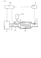
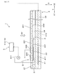
- the exhaust pipe 71 is provided with a catalyst 72 for reducing NOx and a reducing agent supply device 73 for supplying the reducing agent K containing ammonia to the catalyst 72.
- a catalyst 72 for reducing NOx As shown in FIG. 4, the exhaust pipe 71 is provided with a catalyst 72 for reducing NOx and a reducing agent supply device 73 for supplying the reducing agent K containing ammonia to the catalyst 72.
- ammonia as a reducing agent K for NOx is attached to the catalyst carrier.
- the amount of ammonia adhered to the catalyst carrier of the catalyst 72 decreases with the reduction reaction of NOx. Then, when the amount of ammonia adhered to the catalyst carrier is reduced, ammonia is newly replenished from the reducing agent supply device 73 to the catalyst carrier.
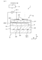
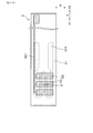
- the first surface 201 of the solid electrolyte body 21 exposed to the detection target gas G forms the outermost surface of the sensor element portion 2.
- the detection electrode 22 provided on the first surface 201 is formed in a state in which the detection target gas G can easily come into contact with the detection electrode 22.
- the surface of the detection electrode 22 of this embodiment is not provided with a protective layer made of a porous ceramic material or the like. Then, the detection target gas G comes into contact with the detection electrode 22 without being diffusion-controlled. It is also possible to provide a protective layer on the surface of the detection electrode 22 so as not to reduce the flow velocity of the detection target gas G as much as possible.
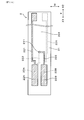
- the lead portion 221 of one detection electrode 22 and the lead portion 221 of the other detection electrode 22 are located near each detection electrode 22 on the first surface 201 of the solid electrolyte body 21. Are connected to each other.
- the lead portion 221 of one detection electrode 22 and the lead portion 221 of the other detection electrode 22 are connected to each other at a portion of the first surface 201 of the solid electrolyte body 21 on the proximal end side X2 in the longitudinal direction X. May be good.
- One reference electrode 23 of the present embodiment is commonly formed at a position facing the entire plurality of detection electrodes 22 via the solid electrolyte body 21. Further, the reference electrode 23 can be individually formed at a position facing each detection electrode 22 via the solid electrolyte body 21. A lead portion 231 connected to the reference electrode 23 is provided on the second surface 202 of the solid electrolyte body 21.
- the detection unit 51 is formed in the sensor control unit 5 connected to the engine control unit 50 of the vehicle.
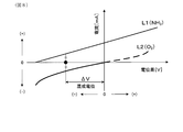
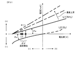
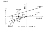
- the detection unit 51 includes a potential difference detection circuit 511 that detects the potential difference ⁇ V generated between the detection electrode 22 and the reference electrode 23, a calculation processing unit 512 that obtains the ammonia concentration by correcting the potential difference ⁇ V by the potential difference detection circuit 511 with the oxygen concentration, and the like.
- the arithmetic processing unit 512 can obtain the ammonia concentration by collating the potential difference ⁇ V and the oxygen concentration with the relationship map by using the relationship map in which the relationship between the potential difference ⁇ V and the ammonia concentration is obtained using the oxygen concentration as a parameter.
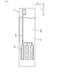
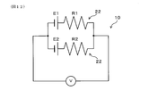
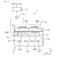
- the two detection electrodes 22A and 22B and the two reference electrodes 23A and 23B are arranged so as to be aligned with each other in the width direction W of the solid electrolyte body 21.
- a lead portion 221 provided on the first surface 201 of the solid electrolyte body 21 is connected to the first detection electrode 22A located on one side of the width direction W.
- the first reference electrode 23A located on one side of the width direction W and the second detection electrode 22B located on the other side of the width direction W include the second surface 202 of the solid electrolyte body 21, the through hole 211, and the solid.
- a series lead portion 222 provided continuously on the first surface 201 of the electrolyte 21 is connected.
- a lead portion 231 provided on the second surface 202 of the solid electrolyte body 21 is connected to the second reference electrode 23B located on the other side in the width direction W.
Landscapes
- Chemical & Material Sciences (AREA)
- Life Sciences & Earth Sciences (AREA)
- Health & Medical Sciences (AREA)
- Physics & Mathematics (AREA)
- Chemical Kinetics & Catalysis (AREA)
- Electrochemistry (AREA)
- Molecular Biology (AREA)
- Analytical Chemistry (AREA)
- Biochemistry (AREA)
- General Health & Medical Sciences (AREA)
- General Physics & Mathematics (AREA)
- Immunology (AREA)
- Pathology (AREA)
- Measuring Oxygen Concentration In Cells (AREA)
Priority Applications (1)
| Application Number | Priority Date | Filing Date | Title |
|---|---|---|---|
| DE112020004482.3T DE112020004482T5 (de) | 2019-09-23 | 2020-08-05 | Gassensor |
Applications Claiming Priority (2)
| Application Number | Priority Date | Filing Date | Title |
|---|---|---|---|
| JP2019172393A JP7071951B2 (ja) | 2019-09-23 | 2019-09-23 | ガスセンサ |
| JP2019-172393 | 2019-09-23 |
Publications (1)
| Publication Number | Publication Date |
|---|---|
| WO2021059758A1 true WO2021059758A1 (ja) | 2021-04-01 |
Family
ID=75157577
Family Applications (1)
| Application Number | Title | Priority Date | Filing Date |
|---|---|---|---|
| PCT/JP2020/029933 Ceased WO2021059758A1 (ja) | 2019-09-23 | 2020-08-05 | ガスセンサ |
Country Status (3)
| Country | Link |
|---|---|
| JP (1) | JP7071951B2 (enExample) |
| DE (1) | DE112020004482T5 (enExample) |
| WO (1) | WO2021059758A1 (enExample) |
Citations (6)
| Publication number | Priority date | Publication date | Assignee | Title |
|---|---|---|---|---|
| JP2001041927A (ja) * | 1999-07-30 | 2001-02-16 | Riken Corp | 窒素酸化物ガスセンサ |
| JP2001221772A (ja) * | 2000-02-08 | 2001-08-17 | Riken Corp | 電気化学センサ |
| JP2009500594A (ja) * | 2005-06-15 | 2009-01-08 | ファーバー・ボリス | 混合ガス測定用に信号出力安定度を改良するためのセンサ条件の方法 |
| JP2017090404A (ja) * | 2015-11-17 | 2017-05-25 | 日本碍子株式会社 | ガスセンサ |
| JP2018173397A (ja) * | 2016-10-24 | 2018-11-08 | 日本碍子株式会社 | アンモニア濃度測定装置,アンモニア濃度測定システム,排ガス処理システム,及びアンモニア濃度測定方法 |
| JP2019158495A (ja) * | 2018-03-12 | 2019-09-19 | 日本碍子株式会社 | ガスセンサ |
Family Cites Families (2)
| Publication number | Priority date | Publication date | Assignee | Title |
|---|---|---|---|---|
| JP6998801B2 (ja) * | 2018-03-12 | 2022-02-04 | 日本碍子株式会社 | ガスセンサ |
| JP7065555B2 (ja) | 2018-03-27 | 2022-05-12 | 日東電工株式会社 | 粘着テープ接合装置 |
-
2019
- 2019-09-23 JP JP2019172393A patent/JP7071951B2/ja active Active
-
2020
- 2020-08-05 WO PCT/JP2020/029933 patent/WO2021059758A1/ja not_active Ceased
- 2020-08-05 DE DE112020004482.3T patent/DE112020004482T5/de not_active Withdrawn
Patent Citations (6)
| Publication number | Priority date | Publication date | Assignee | Title |
|---|---|---|---|---|
| JP2001041927A (ja) * | 1999-07-30 | 2001-02-16 | Riken Corp | 窒素酸化物ガスセンサ |
| JP2001221772A (ja) * | 2000-02-08 | 2001-08-17 | Riken Corp | 電気化学センサ |
| JP2009500594A (ja) * | 2005-06-15 | 2009-01-08 | ファーバー・ボリス | 混合ガス測定用に信号出力安定度を改良するためのセンサ条件の方法 |
| JP2017090404A (ja) * | 2015-11-17 | 2017-05-25 | 日本碍子株式会社 | ガスセンサ |
| JP2018173397A (ja) * | 2016-10-24 | 2018-11-08 | 日本碍子株式会社 | アンモニア濃度測定装置,アンモニア濃度測定システム,排ガス処理システム,及びアンモニア濃度測定方法 |
| JP2019158495A (ja) * | 2018-03-12 | 2019-09-19 | 日本碍子株式会社 | ガスセンサ |
Also Published As
| Publication number | Publication date |
|---|---|
| JP7071951B2 (ja) | 2022-05-19 |
| JP2021050944A (ja) | 2021-04-01 |
| DE112020004482T5 (de) | 2022-06-15 |
Similar Documents
| Publication | Publication Date | Title |
|---|---|---|
| JP5268068B2 (ja) | センサ制御装置及びセンサ制御システム | |
| CN115087863B (zh) | 气体传感器元件 | |
| JP5058224B2 (ja) | NOxセンサ | |
| US20210262974A1 (en) | Gas sensor | |
| JP2002139468A (ja) | ガスセンサ | |
| WO2020145042A1 (ja) | ガス濃度検出装置 | |
| WO2019225594A1 (ja) | アンモニアセンサの劣化判定装置 | |
| JP2009229148A (ja) | ガスセンサ制御装置 | |
| JP7071951B2 (ja) | ガスセンサ | |
| JP2022089378A (ja) | ガス濃度検出装置 | |
| JP7071873B2 (ja) | マルチガスセンサ | |
| JP2019203835A (ja) | マルチガスセンサ | |
| JP2004151017A (ja) | 積層型ガスセンサ素子 | |
| JP7158232B2 (ja) | ガスセンサ | |
| JP7402786B2 (ja) | ガス濃度検出装置 | |
| CN102007399A (zh) | 具有简化电接触的加热的跳跃型探头 | |
| JP7617864B2 (ja) | ガスセンサ素子及びガスセンサ | |
| JPH11352096A (ja) | ガスセンサ素子 | |
| JP7499736B2 (ja) | ガス検出装置 | |
| JP7146619B2 (ja) | アンモニアセンサ | |
| JP7304317B2 (ja) | アンモニア濃度検出装置 | |
| JP7089942B2 (ja) | アンモニア濃度検出装置 | |
| JP7071874B2 (ja) | アンモニア濃度検出装置 | |
| JPH08201340A (ja) | ガスセンサ素子 | |
| WO2022196345A1 (ja) | ガス濃度検出装置 |
Legal Events
| Date | Code | Title | Description |
|---|---|---|---|
| 121 | Ep: the epo has been informed by wipo that ep was designated in this application |
Ref document number: 20867362 Country of ref document: EP Kind code of ref document: A1 |
|
| 122 | Ep: pct application non-entry in european phase |
Ref document number: 20867362 Country of ref document: EP Kind code of ref document: A1 |