WO2021059626A1 - 密封装置 - Google Patents
密封装置 Download PDFInfo
- Publication number
- WO2021059626A1 WO2021059626A1 PCT/JP2020/024349 JP2020024349W WO2021059626A1 WO 2021059626 A1 WO2021059626 A1 WO 2021059626A1 JP 2020024349 W JP2020024349 W JP 2020024349W WO 2021059626 A1 WO2021059626 A1 WO 2021059626A1
- Authority
- WO
- WIPO (PCT)
- Prior art keywords
- protrusion
- sealing member
- sealing
- cylindrical
- flange
- Prior art date
- Legal status (The legal status is an assumption and is not a legal conclusion. Google has not performed a legal analysis and makes no representation as to the accuracy of the status listed.)
- Ceased
Links
Images




Classifications
-
- F—MECHANICAL ENGINEERING; LIGHTING; HEATING; WEAPONS; BLASTING
- F16—ENGINEERING ELEMENTS AND UNITS; GENERAL MEASURES FOR PRODUCING AND MAINTAINING EFFECTIVE FUNCTIONING OF MACHINES OR INSTALLATIONS; THERMAL INSULATION IN GENERAL
- F16C—SHAFTS; FLEXIBLE SHAFTS; ELEMENTS OR CRANKSHAFT MECHANISMS; ROTARY BODIES OTHER THAN GEARING ELEMENTS; BEARINGS
- F16C33/00—Parts of bearings; Special methods for making bearings or parts thereof
- F16C33/72—Sealings
- F16C33/76—Sealings of ball or roller bearings
- F16C33/78—Sealings of ball or roller bearings with a diaphragm, disc, or ring, with or without resilient members
- F16C33/7816—Details of the sealing or parts thereof, e.g. geometry, material
- F16C33/782—Details of the sealing or parts thereof, e.g. geometry, material of the sealing region
-
- F—MECHANICAL ENGINEERING; LIGHTING; HEATING; WEAPONS; BLASTING
- F16—ENGINEERING ELEMENTS AND UNITS; GENERAL MEASURES FOR PRODUCING AND MAINTAINING EFFECTIVE FUNCTIONING OF MACHINES OR INSTALLATIONS; THERMAL INSULATION IN GENERAL
- F16C—SHAFTS; FLEXIBLE SHAFTS; ELEMENTS OR CRANKSHAFT MECHANISMS; ROTARY BODIES OTHER THAN GEARING ELEMENTS; BEARINGS
- F16C19/00—Bearings with rolling contact, for exclusively rotary movement
- F16C19/02—Bearings with rolling contact, for exclusively rotary movement with bearing balls essentially of the same size in one or more circular rows
- F16C19/14—Bearings with rolling contact, for exclusively rotary movement with bearing balls essentially of the same size in one or more circular rows for both radial and axial load
- F16C19/18—Bearings with rolling contact, for exclusively rotary movement with bearing balls essentially of the same size in one or more circular rows for both radial and axial load with two or more rows of balls
- F16C19/181—Bearings with rolling contact, for exclusively rotary movement with bearing balls essentially of the same size in one or more circular rows for both radial and axial load with two or more rows of balls with angular contact
- F16C19/183—Bearings with rolling contact, for exclusively rotary movement with bearing balls essentially of the same size in one or more circular rows for both radial and axial load with two or more rows of balls with angular contact with two rows at opposite angles
- F16C19/184—Bearings with rolling contact, for exclusively rotary movement with bearing balls essentially of the same size in one or more circular rows for both radial and axial load with two or more rows of balls with angular contact with two rows at opposite angles in O-arrangement
- F16C19/186—Bearings with rolling contact, for exclusively rotary movement with bearing balls essentially of the same size in one or more circular rows for both radial and axial load with two or more rows of balls with angular contact with two rows at opposite angles in O-arrangement with three raceways provided integrally on parts other than race rings, e.g. third generation hubs
-
- F—MECHANICAL ENGINEERING; LIGHTING; HEATING; WEAPONS; BLASTING
- F16—ENGINEERING ELEMENTS AND UNITS; GENERAL MEASURES FOR PRODUCING AND MAINTAINING EFFECTIVE FUNCTIONING OF MACHINES OR INSTALLATIONS; THERMAL INSULATION IN GENERAL
- F16C—SHAFTS; FLEXIBLE SHAFTS; ELEMENTS OR CRANKSHAFT MECHANISMS; ROTARY BODIES OTHER THAN GEARING ELEMENTS; BEARINGS
- F16C33/00—Parts of bearings; Special methods for making bearings or parts thereof
- F16C33/72—Sealings
- F16C33/76—Sealings of ball or roller bearings
- F16C33/78—Sealings of ball or roller bearings with a diaphragm, disc, or ring, with or without resilient members
- F16C33/784—Sealings of ball or roller bearings with a diaphragm, disc, or ring, with or without resilient members mounted to a groove in the inner surface of the outer race and extending toward the inner race
- F16C33/7843—Sealings of ball or roller bearings with a diaphragm, disc, or ring, with or without resilient members mounted to a groove in the inner surface of the outer race and extending toward the inner race with a single annular sealing disc
- F16C33/7853—Sealings of ball or roller bearings with a diaphragm, disc, or ring, with or without resilient members mounted to a groove in the inner surface of the outer race and extending toward the inner race with a single annular sealing disc with one or more sealing lips to contact the inner race
-
- F—MECHANICAL ENGINEERING; LIGHTING; HEATING; WEAPONS; BLASTING
- F16—ENGINEERING ELEMENTS AND UNITS; GENERAL MEASURES FOR PRODUCING AND MAINTAINING EFFECTIVE FUNCTIONING OF MACHINES OR INSTALLATIONS; THERMAL INSULATION IN GENERAL
- F16C—SHAFTS; FLEXIBLE SHAFTS; ELEMENTS OR CRANKSHAFT MECHANISMS; ROTARY BODIES OTHER THAN GEARING ELEMENTS; BEARINGS
- F16C33/00—Parts of bearings; Special methods for making bearings or parts thereof
- F16C33/72—Sealings
- F16C33/76—Sealings of ball or roller bearings
- F16C33/78—Sealings of ball or roller bearings with a diaphragm, disc, or ring, with or without resilient members
- F16C33/7869—Sealings of ball or roller bearings with a diaphragm, disc, or ring, with or without resilient members mounted with a cylindrical portion to the inner surface of the outer race and having a radial portion extending inward
- F16C33/7873—Sealings of ball or roller bearings with a diaphragm, disc, or ring, with or without resilient members mounted with a cylindrical portion to the inner surface of the outer race and having a radial portion extending inward with a single sealing ring of generally L-shaped cross-section
- F16C33/7876—Sealings of ball or roller bearings with a diaphragm, disc, or ring, with or without resilient members mounted with a cylindrical portion to the inner surface of the outer race and having a radial portion extending inward with a single sealing ring of generally L-shaped cross-section with sealing lips
-
- F—MECHANICAL ENGINEERING; LIGHTING; HEATING; WEAPONS; BLASTING
- F16—ENGINEERING ELEMENTS AND UNITS; GENERAL MEASURES FOR PRODUCING AND MAINTAINING EFFECTIVE FUNCTIONING OF MACHINES OR INSTALLATIONS; THERMAL INSULATION IN GENERAL
- F16C—SHAFTS; FLEXIBLE SHAFTS; ELEMENTS OR CRANKSHAFT MECHANISMS; ROTARY BODIES OTHER THAN GEARING ELEMENTS; BEARINGS
- F16C33/00—Parts of bearings; Special methods for making bearings or parts thereof
- F16C33/72—Sealings
- F16C33/76—Sealings of ball or roller bearings
- F16C33/78—Sealings of ball or roller bearings with a diaphragm, disc, or ring, with or without resilient members
- F16C33/7869—Sealings of ball or roller bearings with a diaphragm, disc, or ring, with or without resilient members mounted with a cylindrical portion to the inner surface of the outer race and having a radial portion extending inward
- F16C33/7879—Sealings of ball or roller bearings with a diaphragm, disc, or ring, with or without resilient members mounted with a cylindrical portion to the inner surface of the outer race and having a radial portion extending inward with a further sealing ring
- F16C33/7883—Sealings of ball or roller bearings with a diaphragm, disc, or ring, with or without resilient members mounted with a cylindrical portion to the inner surface of the outer race and having a radial portion extending inward with a further sealing ring mounted to the inner race and of generally L-shape, the two sealing rings defining a sealing with box-shaped cross-section
-
- F—MECHANICAL ENGINEERING; LIGHTING; HEATING; WEAPONS; BLASTING
- F16—ENGINEERING ELEMENTS AND UNITS; GENERAL MEASURES FOR PRODUCING AND MAINTAINING EFFECTIVE FUNCTIONING OF MACHINES OR INSTALLATIONS; THERMAL INSULATION IN GENERAL
- F16C—SHAFTS; FLEXIBLE SHAFTS; ELEMENTS OR CRANKSHAFT MECHANISMS; ROTARY BODIES OTHER THAN GEARING ELEMENTS; BEARINGS
- F16C33/00—Parts of bearings; Special methods for making bearings or parts thereof
- F16C33/72—Sealings
- F16C33/76—Sealings of ball or roller bearings
- F16C33/80—Labyrinth sealings
-
- F—MECHANICAL ENGINEERING; LIGHTING; HEATING; WEAPONS; BLASTING
- F16—ENGINEERING ELEMENTS AND UNITS; GENERAL MEASURES FOR PRODUCING AND MAINTAINING EFFECTIVE FUNCTIONING OF MACHINES OR INSTALLATIONS; THERMAL INSULATION IN GENERAL
- F16C—SHAFTS; FLEXIBLE SHAFTS; ELEMENTS OR CRANKSHAFT MECHANISMS; ROTARY BODIES OTHER THAN GEARING ELEMENTS; BEARINGS
- F16C33/00—Parts of bearings; Special methods for making bearings or parts thereof
- F16C33/72—Sealings
- F16C33/76—Sealings of ball or roller bearings
- F16C33/80—Labyrinth sealings
- F16C33/805—Labyrinth sealings in addition to other sealings, e.g. dirt guards to protect sealings with sealing lips
-
- F—MECHANICAL ENGINEERING; LIGHTING; HEATING; WEAPONS; BLASTING
- F16—ENGINEERING ELEMENTS AND UNITS; GENERAL MEASURES FOR PRODUCING AND MAINTAINING EFFECTIVE FUNCTIONING OF MACHINES OR INSTALLATIONS; THERMAL INSULATION IN GENERAL
- F16J—PISTONS; CYLINDERS; SEALINGS
- F16J15/00—Sealings
- F16J15/16—Sealings between relatively-moving surfaces
- F16J15/32—Sealings between relatively-moving surfaces with elastic sealings, e.g. O-rings
- F16J15/3204—Sealings between relatively-moving surfaces with elastic sealings, e.g. O-rings with at least one lip
- F16J15/3232—Sealings between relatively-moving surfaces with elastic sealings, e.g. O-rings with at least one lip having two or more lips
-
- F—MECHANICAL ENGINEERING; LIGHTING; HEATING; WEAPONS; BLASTING
- F16—ENGINEERING ELEMENTS AND UNITS; GENERAL MEASURES FOR PRODUCING AND MAINTAINING EFFECTIVE FUNCTIONING OF MACHINES OR INSTALLATIONS; THERMAL INSULATION IN GENERAL
- F16J—PISTONS; CYLINDERS; SEALINGS
- F16J15/00—Sealings
- F16J15/16—Sealings between relatively-moving surfaces
- F16J15/32—Sealings between relatively-moving surfaces with elastic sealings, e.g. O-rings
- F16J15/3248—Sealings between relatively-moving surfaces with elastic sealings, e.g. O-rings provided with casings or supports
- F16J15/3252—Sealings between relatively-moving surfaces with elastic sealings, e.g. O-rings provided with casings or supports with rigid casings or supports
- F16J15/3256—Sealings between relatively-moving surfaces with elastic sealings, e.g. O-rings provided with casings or supports with rigid casings or supports comprising two casing or support elements, one attached to each surface, e.g. cartridge or cassette seals
-
- F—MECHANICAL ENGINEERING; LIGHTING; HEATING; WEAPONS; BLASTING
- F16—ENGINEERING ELEMENTS AND UNITS; GENERAL MEASURES FOR PRODUCING AND MAINTAINING EFFECTIVE FUNCTIONING OF MACHINES OR INSTALLATIONS; THERMAL INSULATION IN GENERAL
- F16J—PISTONS; CYLINDERS; SEALINGS
- F16J15/00—Sealings
- F16J15/44—Free-space packings
- F16J15/447—Labyrinth packings
-
- B—PERFORMING OPERATIONS; TRANSPORTING
- B60—VEHICLES IN GENERAL
- B60B—VEHICLE WHEELS; CASTORS; AXLES FOR WHEELS OR CASTORS; INCREASING WHEEL ADHESION
- B60B27/00—Hubs
- B60B27/0073—Hubs characterised by sealing means
Definitions
- a sealing device capable of suppressing the intrusion of foreign matter and having high foreign matter discharge performance.
- the resistance of the retaining protrusion is small. Therefore, the work of assembling the sealing device is easy, and when the first sealing member and the second sealing member are combined, the sealing member is less damaged. Further, even if foreign matter invades the peripheral groove from the outside into the outer peripheral surface of the cylindrical protrusion, most of the foreign matter is blocked by the end protrusions formed on the cylindrical protrusion, so that further invasion of foreign matter can be suppressed. Can be done. Further, since an arc-shaped gap is provided between the plurality of retaining protrusions spaced in the circumferential direction, the space between the annular portion of the first sealing member and the flange of the second sealing member. Foreign matter that has entered the inside is easily discharged to the outside through the arc-shaped gap.
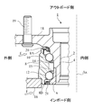
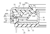
- the sealing device 21 has a composite structure including the first sealing member 24 and the second sealing member 26, that is, a combined structure.
- the flange 38 extends radially outward from the sleeve 36 and faces the annular portion 24B of the first sealing member 24.
- the flange portion 38 is a flat plate and is in a plane perpendicular to the axis of the sleeve 36.
- the flange 38 is composed of a rigid ring 34 and an elastic ring 32. That is, the flange 38 has a flange rigid portion 38A composed of a rigid ring 34 and a flange elastic portion 38B composed of an elastic ring 32.
- FIG. 5 is a partial cross-sectional view of the sealing device 21 at the time of assembly, and the arrow in FIG. 5 indicates the direction in which the second sealing member 26 is brought closer to the first sealing member 24.
- the outer peripheral edge of the end protrusion 50 of the cylindrical protrusion 40 has a third inclined surface 50A on the opposite side of the flange 38.
- the inclination angle ⁇ (see FIG. 6) of the third inclined surface 50A of the end projection 50 with respect to the cylinder centered on the axis of the sealing device 21 is the first inclined surface 46A with respect to the cylinder centered on the axis of the sealing device 21. It is preferable that the inclination angle is ⁇ or less.
- the third inclined surface 50A of the end protrusion 50 formed on the cylindrical protrusion 40 of the second sealing member 26 becomes ,
- the first inclined surface 46A of the retaining protrusion 46 formed on the inner peripheral surface of the mounting cylindrical portion 24A of the first sealing member 24 is brought into contact with the first sealing member 24. If the inclination angle ⁇ of the third inclined surface 50A of the end protrusion 50 is too large, the resistance force of the retaining protrusion 46 becomes large, and the retaining protrusion 46 and / or the end protrusion 50 may be damaged.
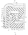
- the cylindrical protrusion 40 does not come into contact with the annular portion 24B of the first sealing member 24. Similar to the labyrinth slip 24F, the cylindrical projecting portion 40 complicates the internal shape of the space 42 between the annular portion 24B of the first sealing member 24 and the flange 38 of the second sealing member 26, and causes foreign matter to be transferred to the lip 24F. It makes it difficult to penetrate toward the side lip 24E located on the inner side in the radial direction.
- the thickness of the labyrinth slip 24F is smaller than the thickness of the labyrinth slip 24F of the embodiment shown in FIG.
- an upward load is applied by the cylindrical protrusion 40, the labyrinth slip 24F, and the side lip 24E. Can be stably supported.
- FIG. 10 shows a sealing device 21 according to another modification of the embodiment.
- the first seal member 24 is not provided with the side lip 24E
- the second seal member 26 has a plurality of water discharge protrusions or fins 60.
- the plurality of water discharge protrusions 60 are supported by the flange 38 and are arranged at equal intervals in the circumferential direction. These water discharge protrusions 60 project into the space 42 toward the annular portion 24B of the first seal member 24.
- the water discharge protrusion 60 is joined to the sleeve 36 side surface (outboard side surface) of the flange rigid portion 38A as a portion of the elastic ring 32 of the second seal member 26. Therefore, the water discharge protrusion 60 is formed of the same material as the elastic ring 32, that is, an elastomer material containing magnetic metal powder and ceramic powder.
- the water discharge protrusion 60 of the second seal member 26 rotates together with the inner ring 6 to bounce off foreign matter such as water in the space 42.
- the bounced foreign matter passes through the gap between the labyrinth slip 24F and the cylindrical protrusion 40, and is finally discharged to the outside through the annular gap 44.
- a sealing device that is arranged between a relatively rotating inner member and an outer member and seals a gap between the inner member and the outer member.
- a first sealing member having a mounting cylindrical portion attached to the outer member and an annular portion extending radially inward from the mounting cylindrical portion toward the inner member.
- a sleeve attached to the inner member, a flange extending radially outward from the sleeve and facing the annular portion of the first sealing member, and a flange extending along the axial direction from the flange of the first sealing member.
- a second sealing member having a cylindrical cylindrical protrusion formed from an elastic material arranged radially inside the mounting cylindrical portion.
- a plurality of retaining protrusions formed of an elastic material are formed on the circumference at intervals in the circumferential direction.
- a circumferential groove is formed which extends continuously on the circumference in which the plurality of retaining protrusions of the first seal member are arranged inside.
- an end protrusion that protrudes radially outward from the circumferential groove and extends continuously on the circumference.
- An annular gap is provided between the mounting cylindrical portion of the first sealing member and the outer edge of the flange of the second sealing member.
- the retaining protrusion of the first sealing member and the peripheral groove of the second sealing member are arranged closer to the annular portion of the first sealing member than the annular gap.
- Clause 3 The sealing device according to Clause 1 or 2, wherein the end of the cylindrical protrusion including the end protrusion on the opposite side of the flange is formed only of the elastic material.
- the end protrusion formed on the cylindrical protrusion of the second sealing member is the inner circumference of the mounting cylindrical portion of the first sealing member. It is brought into contact with the retaining protrusion formed on the surface.
- the end protrusions and the ends of the cylindrical protrusions located radially inside the end protrusions are not reinforced with a rigid material and therefore easily bend, and the end protrusions of the cylindrical protrusions easily come off. Overcome the stop protrusion. Therefore, the first seal member and the second seal member can be easily combined.
- the end protrusion formed on the cylindrical protrusion of the second sealing member is the inner circumference of the mounting cylindrical portion of the first sealing member. It is brought into contact with the first inclined surface of the retaining protrusion formed on the surface. According to this clause, since the inclination angle of the first inclined surface of the retaining protrusion is 60 degrees or less, the end protrusion of the cylindrical protrusion easily gets over the retaining protrusion. Therefore, the first seal member and the second seal member can be easily combined.
- the end protrusion of the cylindrical protrusion once gets over the retaining protrusion, and the retaining protrusion is fitted into the peripheral groove. When it is inserted, the end protrusion is caught by the retaining protrusion, and it is possible to suppress the separation of the two sealing members.
- the third inclined surface of the end protrusion formed on the cylindrical protrusion of the second sealing member is formed on the first sealing member. It is brought into contact with the first inclined surface of the retaining protrusion formed on the inner peripheral surface of the mounting cylindrical portion.
- the inclination angle of the third inclined surface of the end protrusion is such that the inclination angle of the first inclined surface of the retaining protrusion is less than or equal to the inclination angle of the first inclined surface of the retaining protrusion, so that the third inclined surface becomes the first inclined surface.
- the first sealing member has an annular labyrinth slip that projects from the annular portion toward the flange of the second sealing member and does not come into contact with the flange when the sealing device is used.
- the labyrinth slip is arranged radially inside the cylindrical protrusion of the second sealing member.
- the cylindrical protrusion does not come into contact with the annular portion of the first sealing member.
- the sealing device according to any one of Articles 1 to 8, wherein the sealing device is provided.
Landscapes
- Engineering & Computer Science (AREA)
- General Engineering & Computer Science (AREA)
- Mechanical Engineering (AREA)
- Sealing With Elastic Sealing Lips (AREA)
- Sealing Of Bearings (AREA)
- Sealing Using Fluids, Sealing Without Contact, And Removal Of Oil (AREA)
- Sealing Devices (AREA)
Priority Applications (3)
| Application Number | Priority Date | Filing Date | Title |
|---|---|---|---|
| CN202080066409.7A CN114514383B (zh) | 2019-09-24 | 2020-06-22 | 密封装置 |
| JP2021548342A JP7308963B2 (ja) | 2019-09-24 | 2020-06-22 | 密封装置 |
| US17/639,977 US11965558B2 (en) | 2019-09-24 | 2020-06-22 | Sealing device |
Applications Claiming Priority (2)
| Application Number | Priority Date | Filing Date | Title |
|---|---|---|---|
| JP2019-173081 | 2019-09-24 | ||
| JP2019173081 | 2019-09-24 |
Publications (1)
| Publication Number | Publication Date |
|---|---|
| WO2021059626A1 true WO2021059626A1 (ja) | 2021-04-01 |
Family
ID=75166908
Family Applications (1)
| Application Number | Title | Priority Date | Filing Date |
|---|---|---|---|
| PCT/JP2020/024349 Ceased WO2021059626A1 (ja) | 2019-09-24 | 2020-06-22 | 密封装置 |
Country Status (4)
| Country | Link |
|---|---|
| US (1) | US11965558B2 (https=) |
| JP (1) | JP7308963B2 (https=) |
| CN (1) | CN114514383B (https=) |
| WO (1) | WO2021059626A1 (https=) |
Cited By (2)
| Publication number | Priority date | Publication date | Assignee | Title |
|---|---|---|---|---|
| JP2023011188A (ja) * | 2021-07-12 | 2023-01-24 | 内山工業株式会社 | 密封装置 |
| DE102021131523A1 (de) | 2021-12-01 | 2023-06-01 | Schaeffler Technologies AG & Co. KG | Dichtanordnung für ein Lager sowie Lager mit einer solchen Dichtanordnung |
Families Citing this family (2)
| Publication number | Priority date | Publication date | Assignee | Title |
|---|---|---|---|---|
| JP2024003437A (ja) * | 2022-06-27 | 2024-01-15 | Nok株式会社 | 密封装置 |
| DE102023133556A1 (de) * | 2023-08-11 | 2025-02-13 | Schaeffler Technologies AG & Co. KG | Dichtanordnung sowie Lageranordnung mit Dichtanordnung |
Citations (7)
| Publication number | Priority date | Publication date | Assignee | Title |
|---|---|---|---|---|
| US6170992B1 (en) * | 1998-03-12 | 2001-01-09 | Skf Industrie S.P.A. | Sealing device for a rolling contact bearing |
| JP2010185465A (ja) * | 2009-02-10 | 2010-08-26 | Nsk Ltd | 組み合わせシールリング付転がり軸受ユニット |
| JP2014031877A (ja) * | 2011-11-29 | 2014-02-20 | Nsk Ltd | 組み合わせシールリング付転がり軸受ユニット |
| JP2017015213A (ja) * | 2015-07-03 | 2017-01-19 | Nok株式会社 | 密封装置 |
| JP2017057930A (ja) * | 2015-09-16 | 2017-03-23 | Ntn株式会社 | 車輪用軸受装置 |
| JP2017067101A (ja) * | 2015-09-28 | 2017-04-06 | Ntn株式会社 | 車輪用軸受装置 |
| JP2019138457A (ja) * | 2018-02-15 | 2019-08-22 | Ntn株式会社 | 車輪用軸受装置用シール部材及びそれを備えた車輪用軸受装置 |
Family Cites Families (16)
| Publication number | Priority date | Publication date | Assignee | Title |
|---|---|---|---|---|
| US3963248A (en) * | 1974-10-07 | 1976-06-15 | Garlock Inc. | Unitized dual lip seal |
| FR2505951A1 (fr) * | 1981-05-13 | 1982-11-19 | Roulements Soc Nouvelle | Joint d'etancheite tournant entre pieces coaxiales a armature metallique de montage |
| DE3333264A1 (de) | 1983-01-13 | 1985-04-18 | Goetze Ag, 5093 Burscheid | Wellendichtung |
| US4981303A (en) | 1988-10-25 | 1991-01-01 | Nok Corporation | Sealing device |
| US5201529A (en) | 1990-02-16 | 1993-04-13 | Nok Corporation | Sealing device |
| DE10056175A1 (de) | 1999-11-17 | 2001-06-13 | Ntn Toyo Bearing Co Ltd | Wheel Bearing and Sealing Davice Therefor |
| JP2001289254A (ja) | 2000-02-01 | 2001-10-19 | Ntn Corp | 車輪用軸受 |
| IT1319969B1 (it) | 2000-03-17 | 2003-11-12 | Skf Ind Spa | Unita' multifunzionale per cuscinetti a rotolamento. |
| JP4604388B2 (ja) | 2001-05-09 | 2011-01-05 | 日本精工株式会社 | エンコーダ付組み合わせシールリングを備えた転がり軸受ユニット |
| JP4240206B2 (ja) * | 2003-03-14 | 2009-03-18 | Nok株式会社 | 密封装置 |
| JP2007285500A (ja) * | 2006-04-20 | 2007-11-01 | Ntn Corp | 車輪用軸受装置 |
| JP2008267423A (ja) | 2007-04-17 | 2008-11-06 | Uchiyama Mfg Corp | ベアリングシール |
| JP2009197884A (ja) | 2008-02-21 | 2009-09-03 | Ntn Corp | 車輪用軸受装置 |
| US10240677B2 (en) | 2015-04-07 | 2019-03-26 | Freudenberg Sealing Technologies S.A.S. Di Externa Italia S.R.L.U | Gasket |
| JP2017145881A (ja) | 2016-02-17 | 2017-08-24 | 内山工業株式会社 | 密封装置 |
| DE102016207227B4 (de) | 2016-04-28 | 2018-09-13 | Schaeffler Technologies AG & Co. KG | Dichtungsanordnung einer Wälzlagerung, mit einem eine separate Baueinheit bildenden Lüftungsmittel |
-
2020
- 2020-06-22 CN CN202080066409.7A patent/CN114514383B/zh active Active
- 2020-06-22 WO PCT/JP2020/024349 patent/WO2021059626A1/ja not_active Ceased
- 2020-06-22 US US17/639,977 patent/US11965558B2/en active Active
- 2020-06-22 JP JP2021548342A patent/JP7308963B2/ja active Active
Patent Citations (7)
| Publication number | Priority date | Publication date | Assignee | Title |
|---|---|---|---|---|
| US6170992B1 (en) * | 1998-03-12 | 2001-01-09 | Skf Industrie S.P.A. | Sealing device for a rolling contact bearing |
| JP2010185465A (ja) * | 2009-02-10 | 2010-08-26 | Nsk Ltd | 組み合わせシールリング付転がり軸受ユニット |
| JP2014031877A (ja) * | 2011-11-29 | 2014-02-20 | Nsk Ltd | 組み合わせシールリング付転がり軸受ユニット |
| JP2017015213A (ja) * | 2015-07-03 | 2017-01-19 | Nok株式会社 | 密封装置 |
| JP2017057930A (ja) * | 2015-09-16 | 2017-03-23 | Ntn株式会社 | 車輪用軸受装置 |
| JP2017067101A (ja) * | 2015-09-28 | 2017-04-06 | Ntn株式会社 | 車輪用軸受装置 |
| JP2019138457A (ja) * | 2018-02-15 | 2019-08-22 | Ntn株式会社 | 車輪用軸受装置用シール部材及びそれを備えた車輪用軸受装置 |
Cited By (2)
| Publication number | Priority date | Publication date | Assignee | Title |
|---|---|---|---|---|
| JP2023011188A (ja) * | 2021-07-12 | 2023-01-24 | 内山工業株式会社 | 密封装置 |
| DE102021131523A1 (de) | 2021-12-01 | 2023-06-01 | Schaeffler Technologies AG & Co. KG | Dichtanordnung für ein Lager sowie Lager mit einer solchen Dichtanordnung |
Also Published As
| Publication number | Publication date |
|---|---|
| CN114514383A (zh) | 2022-05-17 |
| CN114514383B (zh) | 2024-03-08 |
| JPWO2021059626A1 (https=) | 2021-04-01 |
| US20220333649A1 (en) | 2022-10-20 |
| US11965558B2 (en) | 2024-04-23 |
| JP7308963B2 (ja) | 2023-07-14 |
Similar Documents
| Publication | Publication Date | Title |
|---|---|---|
| JP7228038B2 (ja) | 密封装置 | |
| WO2021059626A1 (ja) | 密封装置 | |
| JP6050080B2 (ja) | 密封型転がり軸受 | |
| KR102536970B1 (ko) | 씰링 기능이 향상된 차량용 휠베어링 | |
| CN210978234U (zh) | 带密封装置的轮毂单元轴承 | |
| WO2018117102A1 (ja) | 密封装置 | |
| US20210115973A1 (en) | Sealing device | |
| KR20200099603A (ko) | 밀봉 장치 및 밀봉 구조 | |
| JP7119992B2 (ja) | ハブユニット軸受 | |
| JP6777466B2 (ja) | プーリユニット | |
| JP6777464B2 (ja) | プーリユニット | |
| US20210116034A1 (en) | Sealing device | |
| JP6985881B2 (ja) | 車輪用軸受装置 | |
| US20200158179A1 (en) | Labyrinth Sealing Device | |
| JP7458198B2 (ja) | 密封装置および密封構造 | |
| JP7175170B2 (ja) | 密封装置 | |
| JP7273963B2 (ja) | 密封装置、密封構造および密封構造の固定方法 | |
| JP2003097725A (ja) | 密封装置 | |
| WO2021235397A1 (ja) | 密封装置 | |
| JP7341778B2 (ja) | 密封装置および密封構造 | |
| JP7390131B2 (ja) | 密封装置および密封構造 | |
| JP2012087901A (ja) | 密封装置および転がり軸受装置 | |
| JP7344697B2 (ja) | 密封装置および密封構造 | |
| KR101948759B1 (ko) | 휠 베어링 밀봉 장치 | |
| JP2012241827A (ja) | 密封装置および転がり軸受 |
Legal Events
| Date | Code | Title | Description |
|---|---|---|---|
| 121 | Ep: the epo has been informed by wipo that ep was designated in this application |
Ref document number: 20868971 Country of ref document: EP Kind code of ref document: A1 |
|
| ENP | Entry into the national phase |
Ref document number: 2021548342 Country of ref document: JP Kind code of ref document: A |
|
| NENP | Non-entry into the national phase |
Ref country code: DE |
|
| 122 | Ep: pct application non-entry in european phase |
Ref document number: 20868971 Country of ref document: EP Kind code of ref document: A1 |