WO2021059626A1 - Sealing device - Google Patents
Sealing device Download PDFInfo
- Publication number
- WO2021059626A1 WO2021059626A1 PCT/JP2020/024349 JP2020024349W WO2021059626A1 WO 2021059626 A1 WO2021059626 A1 WO 2021059626A1 JP 2020024349 W JP2020024349 W JP 2020024349W WO 2021059626 A1 WO2021059626 A1 WO 2021059626A1
- Authority
- WO
- WIPO (PCT)
- Prior art keywords
- protrusion
- sealing member
- sealing
- cylindrical
- flange
- Prior art date
Links
Images


Classifications
-
- F—MECHANICAL ENGINEERING; LIGHTING; HEATING; WEAPONS; BLASTING
- F16—ENGINEERING ELEMENTS AND UNITS; GENERAL MEASURES FOR PRODUCING AND MAINTAINING EFFECTIVE FUNCTIONING OF MACHINES OR INSTALLATIONS; THERMAL INSULATION IN GENERAL
- F16C—SHAFTS; FLEXIBLE SHAFTS; ELEMENTS OR CRANKSHAFT MECHANISMS; ROTARY BODIES OTHER THAN GEARING ELEMENTS; BEARINGS
- F16C33/00—Parts of bearings; Special methods for making bearings or parts thereof
- F16C33/72—Sealings
- F16C33/76—Sealings of ball or roller bearings
- F16C33/78—Sealings of ball or roller bearings with a diaphragm, disc, or ring, with or without resilient members
- F16C33/7816—Details of the sealing or parts thereof, e.g. geometry, material
- F16C33/782—Details of the sealing or parts thereof, e.g. geometry, material of the sealing region
-
- F—MECHANICAL ENGINEERING; LIGHTING; HEATING; WEAPONS; BLASTING
- F16—ENGINEERING ELEMENTS AND UNITS; GENERAL MEASURES FOR PRODUCING AND MAINTAINING EFFECTIVE FUNCTIONING OF MACHINES OR INSTALLATIONS; THERMAL INSULATION IN GENERAL
- F16C—SHAFTS; FLEXIBLE SHAFTS; ELEMENTS OR CRANKSHAFT MECHANISMS; ROTARY BODIES OTHER THAN GEARING ELEMENTS; BEARINGS
- F16C19/00—Bearings with rolling contact, for exclusively rotary movement
- F16C19/02—Bearings with rolling contact, for exclusively rotary movement with bearing balls essentially of the same size in one or more circular rows
- F16C19/14—Bearings with rolling contact, for exclusively rotary movement with bearing balls essentially of the same size in one or more circular rows for both radial and axial load
- F16C19/18—Bearings with rolling contact, for exclusively rotary movement with bearing balls essentially of the same size in one or more circular rows for both radial and axial load with two or more rows of balls
- F16C19/181—Bearings with rolling contact, for exclusively rotary movement with bearing balls essentially of the same size in one or more circular rows for both radial and axial load with two or more rows of balls with angular contact
- F16C19/183—Bearings with rolling contact, for exclusively rotary movement with bearing balls essentially of the same size in one or more circular rows for both radial and axial load with two or more rows of balls with angular contact with two rows at opposite angles
- F16C19/184—Bearings with rolling contact, for exclusively rotary movement with bearing balls essentially of the same size in one or more circular rows for both radial and axial load with two or more rows of balls with angular contact with two rows at opposite angles in O-arrangement
- F16C19/186—Bearings with rolling contact, for exclusively rotary movement with bearing balls essentially of the same size in one or more circular rows for both radial and axial load with two or more rows of balls with angular contact with two rows at opposite angles in O-arrangement with three raceways provided integrally on parts other than race rings, e.g. third generation hubs
-
- F—MECHANICAL ENGINEERING; LIGHTING; HEATING; WEAPONS; BLASTING
- F16—ENGINEERING ELEMENTS AND UNITS; GENERAL MEASURES FOR PRODUCING AND MAINTAINING EFFECTIVE FUNCTIONING OF MACHINES OR INSTALLATIONS; THERMAL INSULATION IN GENERAL
- F16C—SHAFTS; FLEXIBLE SHAFTS; ELEMENTS OR CRANKSHAFT MECHANISMS; ROTARY BODIES OTHER THAN GEARING ELEMENTS; BEARINGS
- F16C33/00—Parts of bearings; Special methods for making bearings or parts thereof
- F16C33/72—Sealings
- F16C33/76—Sealings of ball or roller bearings
- F16C33/78—Sealings of ball or roller bearings with a diaphragm, disc, or ring, with or without resilient members
- F16C33/784—Sealings of ball or roller bearings with a diaphragm, disc, or ring, with or without resilient members mounted to a groove in the inner surface of the outer race and extending toward the inner race
- F16C33/7843—Sealings of ball or roller bearings with a diaphragm, disc, or ring, with or without resilient members mounted to a groove in the inner surface of the outer race and extending toward the inner race with a single annular sealing disc
- F16C33/7853—Sealings of ball or roller bearings with a diaphragm, disc, or ring, with or without resilient members mounted to a groove in the inner surface of the outer race and extending toward the inner race with a single annular sealing disc with one or more sealing lips to contact the inner race
-
- F—MECHANICAL ENGINEERING; LIGHTING; HEATING; WEAPONS; BLASTING
- F16—ENGINEERING ELEMENTS AND UNITS; GENERAL MEASURES FOR PRODUCING AND MAINTAINING EFFECTIVE FUNCTIONING OF MACHINES OR INSTALLATIONS; THERMAL INSULATION IN GENERAL
- F16C—SHAFTS; FLEXIBLE SHAFTS; ELEMENTS OR CRANKSHAFT MECHANISMS; ROTARY BODIES OTHER THAN GEARING ELEMENTS; BEARINGS
- F16C33/00—Parts of bearings; Special methods for making bearings or parts thereof
- F16C33/72—Sealings
- F16C33/76—Sealings of ball or roller bearings
- F16C33/78—Sealings of ball or roller bearings with a diaphragm, disc, or ring, with or without resilient members
- F16C33/7869—Sealings of ball or roller bearings with a diaphragm, disc, or ring, with or without resilient members mounted with a cylindrical portion to the inner surface of the outer race and having a radial portion extending inward
- F16C33/7873—Sealings of ball or roller bearings with a diaphragm, disc, or ring, with or without resilient members mounted with a cylindrical portion to the inner surface of the outer race and having a radial portion extending inward with a single sealing ring of generally L-shaped cross-section
- F16C33/7876—Sealings of ball or roller bearings with a diaphragm, disc, or ring, with or without resilient members mounted with a cylindrical portion to the inner surface of the outer race and having a radial portion extending inward with a single sealing ring of generally L-shaped cross-section with sealing lips
-
- F—MECHANICAL ENGINEERING; LIGHTING; HEATING; WEAPONS; BLASTING
- F16—ENGINEERING ELEMENTS AND UNITS; GENERAL MEASURES FOR PRODUCING AND MAINTAINING EFFECTIVE FUNCTIONING OF MACHINES OR INSTALLATIONS; THERMAL INSULATION IN GENERAL
- F16C—SHAFTS; FLEXIBLE SHAFTS; ELEMENTS OR CRANKSHAFT MECHANISMS; ROTARY BODIES OTHER THAN GEARING ELEMENTS; BEARINGS
- F16C33/00—Parts of bearings; Special methods for making bearings or parts thereof
- F16C33/72—Sealings
- F16C33/76—Sealings of ball or roller bearings
- F16C33/78—Sealings of ball or roller bearings with a diaphragm, disc, or ring, with or without resilient members
- F16C33/7869—Sealings of ball or roller bearings with a diaphragm, disc, or ring, with or without resilient members mounted with a cylindrical portion to the inner surface of the outer race and having a radial portion extending inward
- F16C33/7879—Sealings of ball or roller bearings with a diaphragm, disc, or ring, with or without resilient members mounted with a cylindrical portion to the inner surface of the outer race and having a radial portion extending inward with a further sealing ring
- F16C33/7883—Sealings of ball or roller bearings with a diaphragm, disc, or ring, with or without resilient members mounted with a cylindrical portion to the inner surface of the outer race and having a radial portion extending inward with a further sealing ring mounted to the inner race and of generally L-shape, the two sealing rings defining a sealing with box-shaped cross-section
-
- F—MECHANICAL ENGINEERING; LIGHTING; HEATING; WEAPONS; BLASTING
- F16—ENGINEERING ELEMENTS AND UNITS; GENERAL MEASURES FOR PRODUCING AND MAINTAINING EFFECTIVE FUNCTIONING OF MACHINES OR INSTALLATIONS; THERMAL INSULATION IN GENERAL
- F16C—SHAFTS; FLEXIBLE SHAFTS; ELEMENTS OR CRANKSHAFT MECHANISMS; ROTARY BODIES OTHER THAN GEARING ELEMENTS; BEARINGS
- F16C33/00—Parts of bearings; Special methods for making bearings or parts thereof
- F16C33/72—Sealings
- F16C33/76—Sealings of ball or roller bearings
- F16C33/80—Labyrinth sealings
- F16C33/805—Labyrinth sealings in addition to other sealings, e.g. dirt guards to protect sealings with sealing lips
-
- F—MECHANICAL ENGINEERING; LIGHTING; HEATING; WEAPONS; BLASTING
- F16—ENGINEERING ELEMENTS AND UNITS; GENERAL MEASURES FOR PRODUCING AND MAINTAINING EFFECTIVE FUNCTIONING OF MACHINES OR INSTALLATIONS; THERMAL INSULATION IN GENERAL
- F16J—PISTONS; CYLINDERS; SEALINGS
- F16J15/00—Sealings
- F16J15/16—Sealings between relatively-moving surfaces
- F16J15/32—Sealings between relatively-moving surfaces with elastic sealings, e.g. O-rings
- F16J15/3204—Sealings between relatively-moving surfaces with elastic sealings, e.g. O-rings with at least one lip
- F16J15/3232—Sealings between relatively-moving surfaces with elastic sealings, e.g. O-rings with at least one lip having two or more lips
-
- F—MECHANICAL ENGINEERING; LIGHTING; HEATING; WEAPONS; BLASTING
- F16—ENGINEERING ELEMENTS AND UNITS; GENERAL MEASURES FOR PRODUCING AND MAINTAINING EFFECTIVE FUNCTIONING OF MACHINES OR INSTALLATIONS; THERMAL INSULATION IN GENERAL
- F16J—PISTONS; CYLINDERS; SEALINGS
- F16J15/00—Sealings
- F16J15/16—Sealings between relatively-moving surfaces
- F16J15/32—Sealings between relatively-moving surfaces with elastic sealings, e.g. O-rings
- F16J15/3248—Sealings between relatively-moving surfaces with elastic sealings, e.g. O-rings provided with casings or supports
- F16J15/3252—Sealings between relatively-moving surfaces with elastic sealings, e.g. O-rings provided with casings or supports with rigid casings or supports
- F16J15/3256—Sealings between relatively-moving surfaces with elastic sealings, e.g. O-rings provided with casings or supports with rigid casings or supports comprising two casing or support elements, one attached to each surface, e.g. cartridge or cassette seals
-
- F—MECHANICAL ENGINEERING; LIGHTING; HEATING; WEAPONS; BLASTING
- F16—ENGINEERING ELEMENTS AND UNITS; GENERAL MEASURES FOR PRODUCING AND MAINTAINING EFFECTIVE FUNCTIONING OF MACHINES OR INSTALLATIONS; THERMAL INSULATION IN GENERAL
- F16J—PISTONS; CYLINDERS; SEALINGS
- F16J15/00—Sealings
- F16J15/44—Free-space packings
- F16J15/447—Labyrinth packings
-
- B—PERFORMING OPERATIONS; TRANSPORTING
- B60—VEHICLES IN GENERAL
- B60B—VEHICLE WHEELS; CASTORS; AXLES FOR WHEELS OR CASTORS; INCREASING WHEEL ADHESION
- B60B27/00—Hubs
- B60B27/0073—Hubs characterised by sealing means
Definitions
- a sealing device capable of suppressing the intrusion of foreign matter and having high foreign matter discharge performance.
- the resistance of the retaining protrusion is small. Therefore, the work of assembling the sealing device is easy, and when the first sealing member and the second sealing member are combined, the sealing member is less damaged. Further, even if foreign matter invades the peripheral groove from the outside into the outer peripheral surface of the cylindrical protrusion, most of the foreign matter is blocked by the end protrusions formed on the cylindrical protrusion, so that further invasion of foreign matter can be suppressed. Can be done. Further, since an arc-shaped gap is provided between the plurality of retaining protrusions spaced in the circumferential direction, the space between the annular portion of the first sealing member and the flange of the second sealing member. Foreign matter that has entered the inside is easily discharged to the outside through the arc-shaped gap.
- the sealing device 21 has a composite structure including the first sealing member 24 and the second sealing member 26, that is, a combined structure.
- the flange 38 extends radially outward from the sleeve 36 and faces the annular portion 24B of the first sealing member 24.
- the flange portion 38 is a flat plate and is in a plane perpendicular to the axis of the sleeve 36.
- the flange 38 is composed of a rigid ring 34 and an elastic ring 32. That is, the flange 38 has a flange rigid portion 38A composed of a rigid ring 34 and a flange elastic portion 38B composed of an elastic ring 32.
- FIG. 5 is a partial cross-sectional view of the sealing device 21 at the time of assembly, and the arrow in FIG. 5 indicates the direction in which the second sealing member 26 is brought closer to the first sealing member 24.
- the outer peripheral edge of the end protrusion 50 of the cylindrical protrusion 40 has a third inclined surface 50A on the opposite side of the flange 38.
- the inclination angle ⁇ (see FIG. 6) of the third inclined surface 50A of the end projection 50 with respect to the cylinder centered on the axis of the sealing device 21 is the first inclined surface 46A with respect to the cylinder centered on the axis of the sealing device 21. It is preferable that the inclination angle is ⁇ or less.
- the third inclined surface 50A of the end protrusion 50 formed on the cylindrical protrusion 40 of the second sealing member 26 becomes ,
- the first inclined surface 46A of the retaining protrusion 46 formed on the inner peripheral surface of the mounting cylindrical portion 24A of the first sealing member 24 is brought into contact with the first sealing member 24. If the inclination angle ⁇ of the third inclined surface 50A of the end protrusion 50 is too large, the resistance force of the retaining protrusion 46 becomes large, and the retaining protrusion 46 and / or the end protrusion 50 may be damaged.
- the cylindrical protrusion 40 does not come into contact with the annular portion 24B of the first sealing member 24. Similar to the labyrinth slip 24F, the cylindrical projecting portion 40 complicates the internal shape of the space 42 between the annular portion 24B of the first sealing member 24 and the flange 38 of the second sealing member 26, and causes foreign matter to be transferred to the lip 24F. It makes it difficult to penetrate toward the side lip 24E located on the inner side in the radial direction.
- the thickness of the labyrinth slip 24F is smaller than the thickness of the labyrinth slip 24F of the embodiment shown in FIG.
- an upward load is applied by the cylindrical protrusion 40, the labyrinth slip 24F, and the side lip 24E. Can be stably supported.
- FIG. 10 shows a sealing device 21 according to another modification of the embodiment.
- the first seal member 24 is not provided with the side lip 24E
- the second seal member 26 has a plurality of water discharge protrusions or fins 60.
- the plurality of water discharge protrusions 60 are supported by the flange 38 and are arranged at equal intervals in the circumferential direction. These water discharge protrusions 60 project into the space 42 toward the annular portion 24B of the first seal member 24.
- the water discharge protrusion 60 is joined to the sleeve 36 side surface (outboard side surface) of the flange rigid portion 38A as a portion of the elastic ring 32 of the second seal member 26. Therefore, the water discharge protrusion 60 is formed of the same material as the elastic ring 32, that is, an elastomer material containing magnetic metal powder and ceramic powder.
- the water discharge protrusion 60 of the second seal member 26 rotates together with the inner ring 6 to bounce off foreign matter such as water in the space 42.
- the bounced foreign matter passes through the gap between the labyrinth slip 24F and the cylindrical protrusion 40, and is finally discharged to the outside through the annular gap 44.
- a sealing device that is arranged between a relatively rotating inner member and an outer member and seals a gap between the inner member and the outer member.
- a first sealing member having a mounting cylindrical portion attached to the outer member and an annular portion extending radially inward from the mounting cylindrical portion toward the inner member.
- a sleeve attached to the inner member, a flange extending radially outward from the sleeve and facing the annular portion of the first sealing member, and a flange extending along the axial direction from the flange of the first sealing member.
- a second sealing member having a cylindrical cylindrical protrusion formed from an elastic material arranged radially inside the mounting cylindrical portion.
- a plurality of retaining protrusions formed of an elastic material are formed on the circumference at intervals in the circumferential direction.
- a circumferential groove is formed which extends continuously on the circumference in which the plurality of retaining protrusions of the first seal member are arranged inside.
- an end protrusion that protrudes radially outward from the circumferential groove and extends continuously on the circumference.
- An annular gap is provided between the mounting cylindrical portion of the first sealing member and the outer edge of the flange of the second sealing member.
- the retaining protrusion of the first sealing member and the peripheral groove of the second sealing member are arranged closer to the annular portion of the first sealing member than the annular gap.
- Clause 3 The sealing device according to Clause 1 or 2, wherein the end of the cylindrical protrusion including the end protrusion on the opposite side of the flange is formed only of the elastic material.
- the end protrusion formed on the cylindrical protrusion of the second sealing member is the inner circumference of the mounting cylindrical portion of the first sealing member. It is brought into contact with the retaining protrusion formed on the surface.
- the end protrusions and the ends of the cylindrical protrusions located radially inside the end protrusions are not reinforced with a rigid material and therefore easily bend, and the end protrusions of the cylindrical protrusions easily come off. Overcome the stop protrusion. Therefore, the first seal member and the second seal member can be easily combined.
- the end protrusion formed on the cylindrical protrusion of the second sealing member is the inner circumference of the mounting cylindrical portion of the first sealing member. It is brought into contact with the first inclined surface of the retaining protrusion formed on the surface. According to this clause, since the inclination angle of the first inclined surface of the retaining protrusion is 60 degrees or less, the end protrusion of the cylindrical protrusion easily gets over the retaining protrusion. Therefore, the first seal member and the second seal member can be easily combined.
- the end protrusion of the cylindrical protrusion once gets over the retaining protrusion, and the retaining protrusion is fitted into the peripheral groove. When it is inserted, the end protrusion is caught by the retaining protrusion, and it is possible to suppress the separation of the two sealing members.
- the third inclined surface of the end protrusion formed on the cylindrical protrusion of the second sealing member is formed on the first sealing member. It is brought into contact with the first inclined surface of the retaining protrusion formed on the inner peripheral surface of the mounting cylindrical portion.
- the inclination angle of the third inclined surface of the end protrusion is such that the inclination angle of the first inclined surface of the retaining protrusion is less than or equal to the inclination angle of the first inclined surface of the retaining protrusion, so that the third inclined surface becomes the first inclined surface.
- the first sealing member has an annular labyrinth slip that projects from the annular portion toward the flange of the second sealing member and does not come into contact with the flange when the sealing device is used.
- the labyrinth slip is arranged radially inside the cylindrical protrusion of the second sealing member.
- the cylindrical protrusion does not come into contact with the annular portion of the first sealing member.
- the sealing device according to any one of Articles 1 to 8, wherein the sealing device is provided.
Landscapes
- Engineering & Computer Science (AREA)
- General Engineering & Computer Science (AREA)
- Mechanical Engineering (AREA)
- Sealing With Elastic Sealing Lips (AREA)
- Sealing Of Bearings (AREA)
- Sealing Using Fluids, Sealing Without Contact, And Removal Of Oil (AREA)
Abstract
This sealing device has two seal members. The first seal member has: an attachment cylindrical part that is attached to an outside member; and an annular part that extends radially inward from the attachment cylindrical part toward the inside member. The second seal member has: a sleeve attached to the inside member; a flange that extends radially outward from the sleeve; and a cylindrical protruding part formed from an elastic material that extends from the flange along the axial direction. A plurality of retaining protrusions with intervals therebetween in the circumferential direction are formed on an inner circumferential surface of the attachment cylindrical part of the first seal member. A circumferential groove in the interior of which the plurality of retaining protrusions are arranged and which extends continuously along the circumference is formed on an outer circumferential surface of cylindrical protruding part of the second seal member.
Description
本発明は、密封装置に関する。
The present invention relates to a sealing device.
特許文献1は、転がり軸受に配備されるシール装置を開示する。特許文献1に開示された各シール装置は、それぞれ転がり軸受の内方部材および外方部材に取付けられた2つの環状のシール板を有する。特許文献1の図6に開示されたシール装置においては、これらのシール板に互いに係合する環状の突条が形成されており、シール板の分離が防止されている。
Patent Document 1 discloses a sealing device installed in a rolling bearing. Each sealing device disclosed in Patent Document 1 has two annular sealing plates attached to an inner member and an outer member of a rolling bearing, respectively. In the sealing device disclosed in FIG. 6 of Patent Document 1, annular ridges that engage with each other are formed on these sealing plates to prevent the sealing plates from being separated.
特許文献2は、転がり軸受に配備される組み合わせシールリングを開示する。特許文献2に開示された各組み合わせシールリングは、それぞれ転がり軸受の内輪および外輪に取付けられたスリンガとシールリングを有する。特許文献2の図5と図6に開示されたシール装置においては、スリンガに形成された突条がシールリングに形成された溝に係合されて、スリンガとシールリングの分離が防止されている。
Patent Document 2 discloses a combination seal ring to be deployed on a rolling bearing. Each combination seal ring disclosed in Patent Document 2 has a slinger and a seal ring attached to the inner ring and the outer ring of the rolling bearing, respectively. In the sealing device disclosed in FIGS. 5 and 6 of Patent Document 2, the ridges formed in the slinger are engaged with the grooves formed in the sealing ring to prevent the slinger and the sealing ring from being separated. ..
転がり軸受に配備され、2つのシール部材の組み合わせを有する密封装置においては、上記の通り、これらのシール部材の分離を抑制することが望ましい場合がある。但し、この場合であっても、シール部材を組み合わせて密封措置を組み立てる作業が容易であることが好ましい。また、シール部材を組み合わせる際に、シール部材の損傷が少ないことが好ましい。
In a sealing device that is deployed in a rolling bearing and has a combination of two sealing members, it may be desirable to suppress the separation of these sealing members as described above. However, even in this case, it is preferable that the work of assembling the sealing measures by combining the sealing members is easy. Further, when the seal members are combined, it is preferable that the seal members are less damaged.
さらにこの種の密封装置については、異物(例えば水(泥水または塩水を含む))の多い環境で使用される場合には、異物が密封対象である軸受の内部に侵入しないように保護する機能を高めることが要求される。また、たとえ異物が密封装置に侵入しても、すみやかに異物を排出することができるのが望ましい。
Furthermore, this type of sealing device has a function to protect foreign substances from entering the inside of the bearing to be sealed when used in an environment with a lot of foreign substances (for example, water (including muddy water or salt water)). It is required to increase. Further, it is desirable that the foreign matter can be promptly discharged even if the foreign matter enters the sealing device.
そこで、本発明は、2つのシール部材の分離を抑制することが可能であり、シール部材を組み合わせて密封措置を組み立てる作業が容易であり、シール部材を組み合わせる際に、シール部材の損傷が少なく、異物の侵入を抑制することができ、異物の排出性能が高い密封装置を提供する。
Therefore, in the present invention, it is possible to suppress the separation of the two sealing members, the work of assembling the sealing measures by combining the sealing members is easy, and when the sealing members are combined, the sealing members are less damaged. Provided is a sealing device capable of suppressing the intrusion of foreign matter and having high foreign matter discharge performance.
本発明のある態様に係る密封装置は、相対的に回転する内側部材と外側部材との間に配置され、前記内側部材と前記外側部材との間の間隙を封止する密封装置であって、前記外側部材に取り付けられる取付円筒部と、前記取付円筒部から前記内側部材に向けて径方向内側に広がる環状部を有する、第1のシール部材と、前記内側部材に取り付けられるスリーブと、前記スリーブから径方向外側に広がって前記第1のシール部材の前記環状部と対向するフランジと、前記フランジから軸線方向に沿って延び前記第1のシール部材の前記取付円筒部の径方向内側に配置される弾性材料から形成された円筒状の円筒突出部を有する、第2のシール部材とを備える。前記第1のシール部材の前記取付円筒部の内周面には、周方向に間隔をおいて、弾性材料から形成された複数の抜け止め突起が円周上に形成されている。前記第2のシール部材の前記円筒突出部の外周面には、前記第1のシール部材の前記複数の抜け止め突起が内部に配置される、円周上に連続して延びる周溝が形成されている。前記第2のシール部材の前記円筒突出部の前記フランジとは反対側の端部の外周縁には、前記周溝よりも径方向外側に突出する、円周上に連続して延びる端部突起が形成されている。
The sealing device according to an aspect of the present invention is a sealing device that is arranged between a relatively rotating inner member and an outer member and seals a gap between the inner member and the outer member. A first sealing member having a mounting cylindrical portion attached to the outer member, an annular portion extending radially inward from the mounting cylindrical portion toward the inner member, a sleeve attached to the inner member, and the sleeve. A flange that extends radially outward from the first seal member and faces the annular portion of the first seal member, and extends along the axial direction from the flange and is arranged inside the mounting cylinder portion of the first seal member. It includes a second sealing member having a cylindrical cylindrical protrusion formed from the elastic material. On the inner peripheral surface of the mounting cylinder portion of the first sealing member, a plurality of retaining protrusions formed of an elastic material are formed on the circumference at intervals in the circumferential direction. On the outer peripheral surface of the cylindrical protrusion of the second seal member, a circumferential groove is formed which extends continuously on the circumference in which the plurality of retaining protrusions of the first seal member are arranged inside. ing. On the outer peripheral edge of the end of the cylindrical protrusion of the second sealing member opposite to the flange, an end protrusion that protrudes radially outward from the circumferential groove and extends continuously on the circumference. Is formed.
この態様によれば、第1のシール部材の取付円筒部の内周面に間欠的に形成された複数の抜け止め突起を第2のシール部材の円筒突出部の外周面に形成された周溝に嵌め入れることによって、第1のシール部材と第2のシール部材を組み合わせて密封装置を組み立てることが可能である。組み立て後は、これらの抜け止め突起が周溝に引っ掛かり、2つのシール部材の分離を抑制することが可能である。弾性材料から形成された複数の抜け止め突起は、周方向に間隔をおいているので、単一の抜け止め突起が周方向に連続的に延びる場合に比べて、第1のシール部材と第2のシール部材を組み合わせる際、抜け止め突起の抵抗力が小さい。したがって、密封装置を組み立てる作業は容易であり、第1のシール部材と第2のシール部材を組み合わせる際に、シール部材の損傷が少ない。さらに、外部から円筒突出部の外周面に周溝に異物が侵入したとしても、円筒突出部に形成された端部突起によって、異物の多くが阻止されるので、異物のさらなる侵入を抑制することができる。また、周方向に間隔をおいた複数の抜け止め突起の間には、円弧状の間隙が設けられているので、第1のシール部材の環状部と第2のシール部材のフランジの間の空間内に侵入した異物が円弧状の間隙を通じて外部に排出されやすい。
According to this aspect, a plurality of retaining protrusions intermittently formed on the inner peripheral surface of the mounting cylindrical portion of the first sealing member are formed on the outer peripheral surface of the cylindrical protruding portion of the second sealing member. It is possible to assemble a sealing device by combining the first sealing member and the second sealing member. After assembly, these retaining protrusions are caught in the peripheral groove, and it is possible to suppress the separation of the two sealing members. Since the plurality of retaining protrusions formed of the elastic material are spaced apart in the circumferential direction, the first sealing member and the second retaining protrusion are compared with the case where a single retaining protrusion extends continuously in the circumferential direction. When combining the seal members of, the resistance of the retaining protrusion is small. Therefore, the work of assembling the sealing device is easy, and when the first sealing member and the second sealing member are combined, the sealing member is less damaged. Further, even if foreign matter invades the peripheral groove from the outside into the outer peripheral surface of the cylindrical protrusion, most of the foreign matter is blocked by the end protrusions formed on the cylindrical protrusion, so that further invasion of foreign matter can be suppressed. Can be done. Further, since an arc-shaped gap is provided between the plurality of retaining protrusions spaced in the circumferential direction, the space between the annular portion of the first sealing member and the flange of the second sealing member. Foreign matter that has entered the inside is easily discharged to the outside through the arc-shaped gap.
以下、添付の図面を参照しながら本発明に係る様々な実施の形態を説明する。図面の縮尺は必ずしも正確ではなく、一部の特徴は誇張または省略されることもある。
Hereinafter, various embodiments according to the present invention will be described with reference to the accompanying drawings. Drawing scales are not always accurate and some features may be exaggerated or omitted.
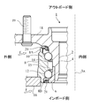
図1は、本発明の実施形態に係る密封装置が使用される転がり軸受の一例である自動車用のハブ軸受を示す。但し、本発明の用途はハブ軸受には限定されず、他の転がり軸受にも本発明は適用可能である。また、以下の説明では、ハブ軸受は、玉軸受であるが、本発明の用途は玉軸受には限定されず、他の種類の転動体を有する、ころ軸受、針軸受などの他の転がり軸受にも本発明は適用可能である。また、自動車以外の機械に使用される転がり軸受にも本発明は適用可能である。
FIG. 1 shows a hub bearing for an automobile, which is an example of a rolling bearing in which the sealing device according to the embodiment of the present invention is used. However, the application of the present invention is not limited to hub bearings, and the present invention can be applied to other rolling bearings. Further, in the following description, the hub bearing is a ball bearing, but the application of the present invention is not limited to the ball bearing, and other rolling bearings such as roller bearings and needle bearings having other types of rolling elements. The present invention is also applicable. The present invention is also applicable to rolling bearings used in machines other than automobiles.
このハブ軸受1は、スピンドル(図示せず)が内部に挿入される孔2を有するハブ(内側部材)4と、ハブ4に取り付けられた内輪(内側部材)6と、これらの外側に配置された外輪(外側部材)8と、ハブ4と外輪8の間に1列に配置された複数の玉10と、内輪6と外輪8の間に1列に配置された複数の玉12と、これらの玉を定位置に保持する複数の保持器14,15とを有する。
The hub bearing 1 is arranged outside the hub (inner member) 4 having a hole 2 into which the spindle (not shown) is inserted, the inner ring (inner member) 6 attached to the hub 4, and the outside thereof. The outer ring (outer member) 8, the plurality of balls 10 arranged in a row between the hub 4 and the outer ring 8, and the plurality of balls 12 arranged in a row between the inner ring 6 and the outer ring 8, and these. It has a plurality of cages 14 and 15 for holding the ball in place.
外輪8が固定されている一方で、ハブ4および内輪6は、スピンドルの回転に伴って回転する。
While the outer ring 8 is fixed, the hub 4 and the inner ring 6 rotate with the rotation of the spindle.
スピンドルおよびハブ軸受1の共通の中心軸線Axは、図1の上下方向に延びている。図1においては、中心軸線Axに対する左側部分のみが示されている。詳細には図示しないが、図1の上側は自動車の車輪が配置される外側(アウトボード側)であり、下側は差動歯車などが配置される内側(インボード側)である。図1に示した外側、内側は、それぞれ径方向の外側、内側を意味する。
The common central axis Ax of the spindle and the hub bearing 1 extends in the vertical direction in FIG. In FIG. 1, only the left side portion with respect to the central axis Ax is shown. Although not shown in detail, the upper side of FIG. 1 is the outside (outboard side) where the wheels of the automobile are arranged, and the lower side is the inside (inboard side) where the differential gears and the like are arranged. The outside and the inside shown in FIG. 1 mean the outside and the inside in the radial direction, respectively.
ハブ軸受1の外輪8は、ハブナックル16に固定される。ハブ4は、外輪8よりも径方向外側に張り出したアウトボード側フランジ18を有する。アウトボード側フランジ18には、ハブボルト19によって、車輪を取り付けることができる。
The outer ring 8 of the hub bearing 1 is fixed to the hub knuckle 16. The hub 4 has an outboard side flange 18 projecting radially outward from the outer ring 8. Wheels can be attached to the outboard side flange 18 by means of hub bolts 19.
外輪8のアウトボード側の端部の付近には、外輪8とハブ4との間の間隙を封止する密封装置20が配置されており、外輪8のインボード側の端部の内側には、外輪8と内輪6との間の間隙を封止する密封装置21が配置されている。これらの密封装置20,21の作用により、ハブ軸受1の内部からのグリース、すなわち潤滑剤の流出が防止されるとともに、外部からハブ軸受1の内部への異物(水(泥水または塩水を含む)およびダストを含む)の流入が防止される。図1において、矢印Fは、外部からの異物の流れの方向の例を示す。
A sealing device 20 for sealing the gap between the outer ring 8 and the hub 4 is arranged near the end of the outer ring 8 on the outboard side, and inside the end of the outer ring 8 on the inboard side. , A sealing device 21 that seals the gap between the outer ring 8 and the inner ring 6 is arranged. By the action of these sealing devices 20 and 21, the outflow of grease, that is, the lubricant from the inside of the hub bearing 1 is prevented, and foreign matter (water (including muddy water or salt water)) from the outside to the inside of the hub bearing 1 is prevented. And the inflow of dust) is prevented. In FIG. 1, the arrow F shows an example of the direction of the flow of foreign matter from the outside.
密封装置20は、ハブ軸受1の回転するハブ4と固定された外輪8のアウトボード側の円筒状の端部8Aとの間に配置され、ハブ4と外輪8との間の間隙を封止する。密封装置21は、ハブ軸受1の回転する内輪6と固定された外輪8のインボード側の端部8Bとの間に配置され、内輪6と外輪8との間の間隙を封止する。
The sealing device 20 is arranged between the rotating hub 4 of the hub bearing 1 and the cylindrical end 8A of the fixed outer ring 8 on the outboard side, and seals the gap between the hub 4 and the outer ring 8. To do. The sealing device 21 is arranged between the rotating inner ring 6 of the hub bearing 1 and the end portion 8B of the fixed outer ring 8 on the inboard side, and seals the gap between the inner ring 6 and the outer ring 8.
図2に示すように、密封装置21は、ハブ軸受1の外輪8のインボード側の端部8Bと、ハブ軸受1の内輪6との間隙内に配置される。密封装置21は環状であるが、図2においては、その左側部分のみが示されている。
As shown in FIG. 2, the sealing device 21 is arranged in the gap between the end portion 8B of the outer ring 8 of the hub bearing 1 on the inboard side and the inner ring 6 of the hub bearing 1. Although the sealing device 21 is annular, only the left side portion thereof is shown in FIG.
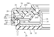
図2から明らかなように、密封装置21は、第1のシール部材24と第2のシール部材26を備える複合構造、すなわち組み合わせ構造を有する。
As is clear from FIG. 2, the sealing device 21 has a composite structure including the first sealing member 24 and the second sealing member 26, that is, a combined structure.
第1のシール部材24は、外輪8に取り付けられ、回転しない固定シール部材である。第1のシール部材24は、弾性環28および剛性環30を有する複合構造である。弾性環28は、弾性材料、例えばエラストマーから形成されている。剛性環30は、剛性材料、例えば金属から形成されており、弾性環28を補強する。剛性環30は、ほぼL字形の断面形状を有する。剛性環30の一部は、弾性環28に埋設されており、弾性環28に密着している。
The first seal member 24 is a fixed seal member that is attached to the outer ring 8 and does not rotate. The first sealing member 24 is a composite structure having an elastic ring 28 and a rigid ring 30. The elastic ring 28 is made of an elastic material, such as an elastomer. The rigid ring 30 is made of a rigid material, for example metal, to reinforce the elastic ring 28. The rigid ring 30 has a substantially L-shaped cross section. A part of the rigid ring 30 is embedded in the elastic ring 28 and is in close contact with the elastic ring 28.
第1のシール部材24は、取付円筒部24A、環状部24B、リップ24C,24D,24E、24F、および円筒突起24Gを有する。
The first sealing member 24 has a mounting cylindrical portion 24A, an annular portion 24B, lips 24C, 24D, 24E, 24F, and a cylindrical protrusion 24G.
取付円筒部24Aは外輪8に取り付けられる。例えば、取付円筒部24Aは、外輪8の端部8Bに締まり嵌め方式で嵌め入れられる(すなわち圧入される)。環状部24Bは、円環状であって、取付円筒部24Aの径方向内側に配置され、取付円筒部24Aから内輪6に向けて径方向内側に広がる。取付円筒部24Aと環状部24Bは、剛性環30と弾性環28から構成されている。
The mounting cylindrical portion 24A is mounted on the outer ring 8. For example, the mounting cylindrical portion 24A is fitted (that is, press-fitted) into the end portion 8B of the outer ring 8 by a tightening method. The annular portion 24B is an annular shape and is arranged radially inside the mounting cylindrical portion 24A, and extends radially inward from the mounting cylindrical portion 24A toward the inner ring 6. The mounting cylindrical portion 24A and the annular portion 24B are composed of a rigid ring 30 and an elastic ring 28.
リップ24C,24D,24Eは、環状部24Bの内側端から第2のシール部材26に向けて延びる。リップ24Fは、環状部24Bの途中部分から第2のシール部材26に向けて延びる。円筒突起24Gは、環状部24Bの内側端からアウトボード側に向けて密封装置21の軸線方向に沿って延びる。リップ24C,24D,24E、24F、および円筒突起24Gは、弾性環28から構成されている。
The lips 24C, 24D, 24E extend from the inner end of the annular portion 24B toward the second sealing member 26. The lip 24F extends from an intermediate portion of the annular portion 24B toward the second sealing member 26. The cylindrical protrusion 24G extends from the inner end of the annular portion 24B toward the outboard side along the axial direction of the sealing device 21. The lips 24C, 24D, 24E, 24F, and the cylindrical protrusion 24G are composed of an elastic ring 28.
第2のシール部材26は、スリンガーすなわち回転シール部材とも呼ぶことができる。第2のシール部材26は、内輪6に取り付けられており、内輪6の回転時に、第2のシール部材26は内輪6とともに回転し、外部から飛散して来る異物を跳ね飛ばす。
The second seal member 26 can also be called a slinger, that is, a rotary seal member. The second seal member 26 is attached to the inner ring 6, and when the inner ring 6 rotates, the second seal member 26 rotates together with the inner ring 6 to repel foreign matter scattered from the outside.
この実施形態では、第2のシール部材26も、弾性環32および剛性環34を有する複合構造である。剛性環34は、剛性材料、例えば金属から形成されている。剛性環34は、ほぼL字形の断面形状を有する。
In this embodiment, the second seal member 26 also has a composite structure having an elastic ring 32 and a rigid ring 34. The rigid ring 34 is made of a rigid material, for example metal. The rigid ring 34 has a substantially L-shaped cross section.
第2のシール部材26は、スリーブ36、フランジ38および円筒突出部40を有する。
The second sealing member 26 has a sleeve 36, a flange 38, and a cylindrical protrusion 40.
スリーブ36は、剛性環34のみから構成されており、内輪6に取り付けられる。具体的には、スリーブ36には、内輪6の端部が締まり嵌め方式で嵌め入れられる(すなわち圧入される)。
The sleeve 36 is composed of only the rigid ring 34 and is attached to the inner ring 6. Specifically, the end portion of the inner ring 6 is fitted (that is, press-fitted) into the sleeve 36 by a tightening method.
フランジ38は、スリーブ36から径方向外側に広がって第1のシール部材24の環状部24Bと対向する。フランジ部分38は平板であり、スリーブ36の軸線に対して垂直な平面内にある。フランジ38は、剛性環34と弾性環32から構成されている。すなわち、フランジ38は、剛性環34から構成されるフランジ剛性部分38Aと、弾性環32から構成されるフランジ弾性部分38Bを有する。フランジ弾性部分38Bは、フランジ剛性部分38Aのスリーブ36と反対側の面(インボード側の面)の全体に密着させられ、フランジ剛性部分38Aの外周端面にも密着させられている。
The flange 38 extends radially outward from the sleeve 36 and faces the annular portion 24B of the first sealing member 24. The flange portion 38 is a flat plate and is in a plane perpendicular to the axis of the sleeve 36. The flange 38 is composed of a rigid ring 34 and an elastic ring 32. That is, the flange 38 has a flange rigid portion 38A composed of a rigid ring 34 and a flange elastic portion 38B composed of an elastic ring 32. The flange elastic portion 38B is brought into close contact with the entire surface (inboard side surface) of the flange rigid portion 38A opposite to the sleeve 36, and is also brought into close contact with the outer peripheral end surface of the flange rigid portion 38A.
円筒突出部40は、フランジ38から密封装置21の軸線方向に沿って延び、第1のシール部材24の取付円筒部24Aの径方向内側、スリーブ36の径方向外側に配置されている。円筒突出部40は、弾性環32から構成されており、フランジ弾性部分38Bの外端縁38Cに一体に結合されている。
The cylindrical projecting portion 40 extends from the flange 38 along the axial direction of the sealing device 21 and is arranged on the radial inside of the mounting cylindrical portion 24A of the first sealing member 24 and on the radial outside of the sleeve 36. The cylindrical protrusion 40 is composed of an elastic ring 32, and is integrally connected to the outer end edge 38C of the flange elastic portion 38B.
この実施形態では、フランジ弾性部分38Bを利用して、内輪6の回転速度を計測することができる。具体的には、弾性環32は、磁性金属粉およびセラミックス粉を含有するエラストマー材料で形成されており、磁性金属粉によって多数のS極とN極を有する。フランジ弾性部分38Bにおいては、円周方向に等角間隔をおいて多数のS極とN極が交互に配置されている。図示しない磁気式ロータリーエンコーダーによって、フランジ弾性部分38Bの回転角度を測定することができる。弾性環32の材料は、金属粉を含有するため、通常のエラストマー材料よりも硬度が高く、異物による損傷を受けにくい。
In this embodiment, the rotational speed of the inner ring 6 can be measured by using the flange elastic portion 38B. Specifically, the elastic ring 32 is formed of an elastomer material containing magnetic metal powder and ceramic powder, and has a large number of S poles and N poles depending on the magnetic metal powder. In the flange elastic portion 38B, a large number of S poles and N poles are alternately arranged at equiangular intervals in the circumferential direction. The rotation angle of the flange elastic portion 38B can be measured by a magnetic rotary encoder (not shown). Since the material of the elastic ring 32 contains metal powder, it has a higher hardness than a normal elastomer material and is not easily damaged by foreign matter.
第1のシール部材24のリップ24Cは、環状部24Bの内側端から径方向内側かつアウトボード側に延びるラジアルリップである。リップ24Cは、第2のシール部材26のスリーブ36に向けて延びる。リップ24Cは、主にハブ軸受1の内部からの潤滑剤の流出を阻止する役割を担うグリースリップである。リップ24Cの先端は、スリーブ36に接触してもよいし、接触しなくてもよい。
The lip 24C of the first sealing member 24 is a radial lip extending radially inward from the inner end of the annular portion 24B and toward the outboard side. The lip 24C extends toward the sleeve 36 of the second sealing member 26. The lip 24C is a grease lip that mainly plays a role of preventing the outflow of the lubricant from the inside of the hub bearing 1. The tip of the lip 24C may or may not contact the sleeve 36.
リップ24Dは、環状部24Bの内側端から径方向内側かつインボード側に延びるラジアルリップである。リップ24Dも、第2のシール部材26のスリーブ36に向けて延びる。リップ24Dは、主に外部からハブ軸受1の内部への異物の流入を阻止する役割を担うダストリップである。リップ24Dの先端は、スリーブ36に接触してもよいし、接触しなくてもよい。
The lip 24D is a radial lip extending radially inward and inboard side from the inner end of the annular portion 24B. The lip 24D also extends toward the sleeve 36 of the second sealing member 26. The lip 24D is a dust strip that mainly serves to prevent foreign matter from flowing into the hub bearing 1 from the outside. The tip of the lip 24D may or may not contact the sleeve 36.
リップ24Eは、環状部24Bの内側端から径方向外側かつインボード側に延びるサイドリップである。サイドリップ24Eは、第2のシール部材26のフランジ38に向けて延びる。サイドリップ24Eも主に外部からハブ軸受1の内部への異物の流入を阻止する役割を担う。リップ24Eの先端は、フランジ38に接触してもよいし、接触しなくてもよい。
The lip 24E is a side lip extending radially outward and inboard side from the inner end of the annular portion 24B. The side lip 24E extends toward the flange 38 of the second sealing member 26. The side lip 24E also mainly plays a role of preventing the inflow of foreign matter from the outside into the inside of the hub bearing 1. The tip of the lip 24E may or may not contact the flange 38.
封止性能を高めるためには、グリースリップ24C、ダストリップ24Dおよびサイドリップ24Eの先端は、第2のシール部材26に接触するのが好ましい。しかし、第2のシール部材26ひいては内輪6に与えるトルクを低減するためには、グリースリップ24C、ダストリップ24Dおよびサイドリップ24Eの先端は、第2のシール部材26に接触しないのが好ましい。
In order to improve the sealing performance, it is preferable that the tips of the grease lip 24C, the dust strip 24D and the side lip 24E come into contact with the second sealing member 26. However, in order to reduce the torque applied to the second sealing member 26 and thus the inner ring 6, it is preferable that the tips of the grease lip 24C, the dust strip 24D and the side lip 24E do not come into contact with the second sealing member 26.
環状のリップ24Fは、環状部24Bの途中部分から第2のシール部材26に向けて延びる。密封装置21の使用時には、リップ24Fの先端は第2のシール部材26に接触しない。リップ24Fは、第1のシール部材24の環状部24Bと第2のシール部材26のフランジ38の間の空間42の内部形状を複雑化し、異物をリップ24Fの径方向内側に位置するサイドリップ24Eに向けて侵入しにくくするラビリンスリップである。ラビリンスリップ24Fは、第2のシール部材26の円筒突出部40よりも径方向内側に配置されている。
The annular lip 24F extends from an intermediate portion of the annular portion 24B toward the second sealing member 26. When the sealing device 21 is used, the tip of the lip 24F does not come into contact with the second sealing member 26. The lip 24F complicates the internal shape of the space 42 between the annular portion 24B of the first sealing member 24 and the flange 38 of the second sealing member 26, and the side lip 24E located inside the lip 24F in the radial direction. It is a labyrinth slip that makes it difficult to invade toward. The labyrinth slip 24F is arranged radially inside the cylindrical protrusion 40 of the second sealing member 26.
第1のシール部材24の取付円筒部24Aのインボード側の先端と、第2のシール部材26のフランジ38の外端縁38Cとの間には、円環状の間隙44が設けられている。間隙44を通じて、第1のシール部材24の環状部24Bと第2のシール部材26のフランジ38の間の空間42内に、異物が侵入することがある。逆に、空間42内の異物は、間隙44を通じて排出することができる。
An annular gap 44 is provided between the tip of the mounting cylindrical portion 24A of the first sealing member 24 on the inboard side and the outer edge 38C of the flange 38 of the second sealing member 26. Foreign matter may enter the space 42 between the annular portion 24B of the first sealing member 24 and the flange 38 of the second sealing member 26 through the gap 44. On the contrary, the foreign matter in the space 42 can be discharged through the gap 44.
図2から図4に示すように、第1のシール部材24の取付円筒部24Aの円柱形の内周面には、周方向に間隔をおいて、弾性材料から形成された複数の抜け止め突起46が円周上に形成されている。図4から明らかなように、各抜け止め突起46は、密封装置21の軸線方向に沿って見て、円環状の間隙44に重なっている。周方向に間隔をおいた複数の抜け止め突起46の間には、円弧状の間隙52が設けられている
As shown in FIGS. 2 to 4, a plurality of retaining protrusions formed of an elastic material are provided on the inner peripheral surface of the cylinder of the mounting cylindrical portion 24A of the first sealing member 24 at intervals in the circumferential direction. 46 is formed on the circumference. As is clear from FIG. 4, each retaining protrusion 46 overlaps the annular gap 44 when viewed along the axial direction of the sealing device 21. An arcuate gap 52 is provided between the plurality of retaining protrusions 46 spaced in the circumferential direction.
図4においては、抜け止め突起46の数は4であるが、抜け止め突起46の数は図示に限られず、2以上であればよい。好ましくは、抜け止め突起46の数は3以上である。
In FIG. 4, the number of retaining protrusions 46 is 4, but the number of retaining protrusions 46 is not limited to the drawing, and may be 2 or more. Preferably, the number of retaining protrusions 46 is 3 or more.
第2のシール部材26の円筒突出部40の外周面には、円周上に連続して延びる周溝48が形成されている。周溝48内には、第1のシール部材24の複数の抜け止め突起46が配置される。
A peripheral groove 48 extending continuously on the circumference is formed on the outer peripheral surface of the cylindrical protrusion 40 of the second seal member 26. A plurality of retaining protrusions 46 of the first sealing member 24 are arranged in the peripheral groove 48.
第2のシール部材26の円筒突出部40のフランジ38とは反対側の端部の外周縁には、周溝48よりも径方向外側に突出する、円周上に連続して延びる端部突起50が形成されている。端部突起50は周溝48の一端を画定し、フランジ38の外端縁38Cは周溝48の他端を画定する。
On the outer peripheral edge of the end of the cylindrical protrusion 40 of the second sealing member 26 opposite to the flange 38, an end protrusion that protrudes radially outward from the circumferential groove 48 and extends continuously on the circumference. 50 is formed. The end protrusion 50 defines one end of the peripheral groove 48, and the outer edge 38C of the flange 38 defines the other end of the peripheral groove 48.
複数の抜け止め突起46は、組み合わせられた第1のシール部材24と第2のシール部材26の分離を抑制する。具体的には、第1のシール部材24の取付円筒部24Aの内周面に間欠的に形成された複数の抜け止め突起46を第2のシール部材26の円筒突出部40の外周面に形成された周溝48に嵌め入れることによって、第1のシール部材24と第2のシール部材26を組み合わせて密封装置21を組み立てることが可能である。組み立て後は、これらの抜け止め突起46が周溝48に引っ掛かり、2つのシール部材24,26の分離を抑制することが可能である。
The plurality of retaining protrusions 46 suppress the separation of the combined first seal member 24 and the second seal member 26. Specifically, a plurality of retaining protrusions 46 intermittently formed on the inner peripheral surface of the mounting cylindrical portion 24A of the first sealing member 24 are formed on the outer peripheral surface of the cylindrical protruding portion 40 of the second sealing member 26. By fitting the peripheral groove 48 into the groove 48, it is possible to assemble the sealing device 21 by combining the first sealing member 24 and the second sealing member 26. After assembly, these retaining protrusions 46 are caught in the peripheral groove 48, and it is possible to suppress the separation of the two sealing members 24 and 26.
このように抜け止め突起46が周溝48に引っ掛かり、2つのシール部材24,26の分離を抑制するので、第1のシール部材24のグリースリップ24Cおよびダストリップ24Dは、第2のシール部材26のスリーブ36を緊縛する必要がない。つまり、グリースリップ24Cおよびダストリップ24Dがスリーブ36に強い力で押し付けられていれば、2つのシール部材24,26の分離が抑制される。
In this way, the retaining protrusion 46 is caught in the peripheral groove 48 and suppresses the separation of the two sealing members 24 and 26, so that the grease lip 24C and the dust strip 24D of the first sealing member 24 are the second sealing member 26. There is no need to bind the sleeve 36 of the. That is, if the grease lip 24C and the dust strip 24D are pressed against the sleeve 36 with a strong force, the separation of the two sealing members 24 and 26 is suppressed.
一方、第2のシール部材26ひいては内輪6に与えるトルクを低減するためには、グリースリップ24Cおよびダストリップ24Dがスリーブ36に接触しないことが好ましい。この場合でも、抜け止め突起46が周溝48に引っ掛かることによって、2つのシール部材24,26の分離が抑制される。
On the other hand, in order to reduce the torque applied to the second sealing member 26 and thus the inner ring 6, it is preferable that the grease lip 24C and the dust strip 24D do not come into contact with the sleeve 36. Even in this case, the retaining protrusion 46 is caught in the peripheral groove 48, so that the separation of the two sealing members 24 and 26 is suppressed.
図5は、密封装置21の組み立て時の部分断面図であり、図5の矢印は第1のシール部材24に第2のシール部材26が接近させられる方向を示す。
FIG. 5 is a partial cross-sectional view of the sealing device 21 at the time of assembly, and the arrow in FIG. 5 indicates the direction in which the second sealing member 26 is brought closer to the first sealing member 24.
弾性材料から形成された複数の抜け止め突起46は、周方向に間隔をおいているので、単一の抜け止め突起が周方向に連続的に延びる場合に比べて、第1のシール部材24と第2のシール部材26を組み合わせる際、抜け止め突起46の抵抗力が小さい。したがって、密封装置21を組み立てる作業は容易であり、第1のシール部材24と第2のシール部材26を組み合わせる際に、シール部材24,26(例えば、抜け止め突起46、端部突起50)の損傷が少ない。
Since the plurality of retaining protrusions 46 formed of the elastic material are spaced apart in the circumferential direction, the first sealing member 24 and the first sealing member 24 are compared with the case where a single retaining protrusion extends continuously in the circumferential direction. When the second seal member 26 is combined, the resistance force of the retaining protrusion 46 is small. Therefore, the work of assembling the sealing device 21 is easy, and when the first sealing member 24 and the second sealing member 26 are combined, the sealing members 24 and 26 (for example, the retaining protrusion 46 and the end protrusion 50) are combined. There is little damage.
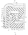
図6は、密封装置21の部分拡大断面図であり、図6の矢印Fは異物の流れの方向の例を示す。外部から円筒突出部40の外周面に周溝48に異物が侵入したとしても、円筒突出部40に形成された端部突起50によって、異物の多くが阻止されるので、異物のさらなる侵入を抑制することができる。また、周方向に間隔をおいた複数の抜け止め突起46の間には、円弧状の間隙52が設けられているので(図4参照)、第1のシール部材24の環状部24Bと第2のシール部材26のフランジ38の間の空間42内に侵入した異物が円弧状の間隙52を通じて排出されやすい。
FIG. 6 is a partially enlarged cross-sectional view of the sealing device 21, and arrow F in FIG. 6 shows an example of the flow direction of foreign matter. Even if foreign matter invades the peripheral groove 48 from the outside into the outer peripheral surface of the cylindrical protrusion 40, most of the foreign matter is blocked by the end protrusion 50 formed in the cylindrical protrusion 40, so that further invasion of foreign matter is suppressed. can do. Further, since an arc-shaped gap 52 is provided between the plurality of retaining protrusions 46 spaced in the circumferential direction (see FIG. 4), the annular portion 24B and the second sealing member 24 of the first seal member 24 are provided. Foreign matter that has entered the space 42 between the flanges 38 of the seal member 26 is likely to be discharged through the arcuate gap 52.
第1のシール部材24の抜け止め突起46および第2のシール部材26の周溝48は、円環状の間隙44よりも第1のシール部材24の環状部24Bの近くに配置されている。周溝48は、円環状の間隙44よりも径方向内側に形成されている。この実施形態のように内輪6が回転する場合、内輪6に取り付けられた第2のシール部材26も回転し、第2のシール部材26の円筒突出部40の外周面に形成された周溝48に侵入した異物が跳ね飛ばされる。周溝48は円環状の間隙44よりも径方向内側に形成されているので、周溝48から跳ね飛ばされた異物は、円環状の間隙44を通じて密封装置21の外部に排出されやすい。
The retaining protrusion 46 of the first seal member 24 and the peripheral groove 48 of the second seal member 26 are arranged closer to the annular portion 24B of the first seal member 24 than the annular gap 44. The peripheral groove 48 is formed radially inside the annular gap 44. When the inner ring 6 rotates as in this embodiment, the second seal member 26 attached to the inner ring 6 also rotates, and the peripheral groove 48 formed on the outer peripheral surface of the cylindrical protrusion 40 of the second seal member 26 also rotates. Foreign matter that has invaded the area is bounced off. Since the peripheral groove 48 is formed radially inside the annular gap 44, foreign matter splashed from the peripheral groove 48 is likely to be discharged to the outside of the sealing device 21 through the annular gap 44.
図5に示すように、第1のシール部材24と第2のシール部材26を組み合わせて密封装置21を組み立てる際、第2のシール部材26の円筒突出部40に形成された端部突起50は、第1のシール部材24の取付円筒部24Aの内周面に形成された抜け止め突起46に接触させられる。端部突起50を含む円筒突出部40は、弾性材料のみで構成され剛性材料で補強されていないため撓みやすく、円筒突出部40の端部突起50は容易に抜け止め突起46を乗り越える。したがって、容易に第1のシール部材24と第2のシール部材26を組み合わせることができる。
As shown in FIG. 5, when the sealing device 21 is assembled by combining the first sealing member 24 and the second sealing member 26, the end protrusion 50 formed on the cylindrical protrusion 40 of the second sealing member 26 is formed. , The first seal member 24 is brought into contact with the retaining protrusion 46 formed on the inner peripheral surface of the mounting cylindrical portion 24A. The cylindrical protrusion 40 including the end protrusion 50 is easily bent because it is made of only an elastic material and is not reinforced with a rigid material, and the end protrusion 50 of the cylindrical protrusion 40 easily gets over the retaining protrusion 46. Therefore, the first seal member 24 and the second seal member 26 can be easily combined.
この実施形態では、円筒突出部40の全体が弾性材料のみで構成されているが、図7に示す変形例のように、円筒突出部40の基端部が剛性材料で補強されていてもよい。この変形例でも、端部突起50を含む円筒突出部40のフランジ38とは反対側の端部は、弾性材料のみから形成されている。したがって、端部突起50と端部突起50の径方向内側に位置する円筒突出部40の先端部は、剛性材料で補強されていないため撓みやすく、円筒突出部40の端部突起50は容易に抜け止め突起46を乗り越える。したがって、容易に第1のシール部材24と第2のシール部材26を組み合わせることができる。
In this embodiment, the entire cylindrical protrusion 40 is made of only an elastic material, but as in the modified example shown in FIG. 7, the base end portion of the cylindrical protrusion 40 may be reinforced with a rigid material. .. Also in this modification, the end portion of the cylindrical protrusion 40 including the end protrusion 50 on the opposite side to the flange 38 is formed only from the elastic material. Therefore, the tip of the end protrusion 50 and the cylindrical protrusion 40 located radially inside the end protrusion 50 is easily bent because it is not reinforced with a rigid material, and the end protrusion 50 of the cylindrical protrusion 40 is easily formed. Overcome the retaining protrusion 46. Therefore, the first seal member 24 and the second seal member 26 can be easily combined.
図6に示すように、円筒突出部40の内周面は、円柱面40Aと、円柱面40Aに隣接する円錐台面40Bを有し、円錐台面40Bは円柱面40Aよりもフランジ38に近く配置されている。円錐台面40Bはフランジ38から離れるにつれて小さくなる直径を有する。
As shown in FIG. 6, the inner peripheral surface of the cylindrical protrusion 40 has a cylindrical surface 40A and a conical base surface 40B adjacent to the cylindrical surface 40A, and the conical base surface 40B is arranged closer to the flange 38 than the cylindrical surface 40A. ing. The conical base surface 40B has a diameter that decreases as the distance from the flange 38 increases.
この円筒突出部40の内周面の形状によれば、円筒突出部40は、フランジ38に近く配置された円錐台面40Bとフランジ38の遠くに配置された円柱面40Aの境界40C付近で、径方向内側に向けて屈曲しやすい。図5および図6の仮想線は、屈曲した円筒突出部40の輪郭を示す。第1のシール部材24と第2のシール部材26を組み合わせて密封装置21を組み立てる際、第2のシール部材26の円筒突出部40に形成された端部突起50は、第1のシール部材24の取付円筒部24Aの内周面に形成された抜け止め突起46に接触させられる(図5参照)。この時、端部突起50には抜け止め突起46から径方向内側に向けて押圧され、このため円筒突出部40は内側に向けて屈曲させられるので、円筒突出部40の端部突起50は容易に抜け止め突起46を乗り越える。したがって、容易に第1のシール部材24と第2のシール部材26を組み合わせることができる。
According to the shape of the inner peripheral surface of the cylindrical projecting portion 40, the cylindrical projecting portion 40 has a diameter near the boundary 40C between the conical base surface 40B arranged near the flange 38 and the cylindrical surface 40A arranged far from the flange 38. Easy to bend inward in the direction. The imaginary lines in FIGS. 5 and 6 show the contours of the bent cylindrical protrusion 40. When the sealing device 21 is assembled by combining the first sealing member 24 and the second sealing member 26, the end protrusion 50 formed on the cylindrical protrusion 40 of the second sealing member 26 is the first sealing member 24. It is brought into contact with the retaining protrusion 46 formed on the inner peripheral surface of the mounting cylindrical portion 24A of the above (see FIG. 5). At this time, the end protrusion 50 is pressed inward from the retaining protrusion 46 in the radial direction, so that the cylindrical protrusion 40 is bent inward, so that the end protrusion 50 of the cylindrical protrusion 40 is easy. Overcome the retaining protrusion 46. Therefore, the first seal member 24 and the second seal member 26 can be easily combined.
図3、図5および図6に示すように、各抜け止め突起46は、環状部24Bと反対側にある第1の傾斜面46Aと、環状部24B側にある第2の傾斜面46Bを有する。第1の傾斜面46Aと第2の傾斜面46Bは、湾曲面と接続されており、各抜け止め突起46は横から見ると頂部が湾曲したほぼ三角形の輪郭を有する。
As shown in FIGS. 3, 5 and 6, each retaining protrusion 46 has a first inclined surface 46A on the side opposite to the annular portion 24B and a second inclined surface 46B on the annular portion 24B side. .. The first inclined surface 46A and the second inclined surface 46B are connected to a curved surface, and each retaining protrusion 46 has a substantially triangular contour with a curved top when viewed from the side.
第1のシール部材24と第2のシール部材26を組み合わせて密封装置21を組み立てる際、図5に示すように、第2のシール部材26の円筒突出部40に形成された端部突起50は、第1のシール部材24の取付円筒部24Aの内周面に形成された抜け止め突起46の第1の傾斜面46Aに接触させられる。第1の傾斜面46Aの傾斜角α(図6参照)が大きすぎると、抜け止め突起46の抵抗力が大きくなり、抜け止め突起46および/または端部突起50が損傷するおそれがある。そこで、密封装置21の軸線を中心とする円柱に対する抜け止め突起46の第1の傾斜面46Aの傾斜角αが60度以下であることが好ましい。抜け止め突起46の第1の傾斜面46Aの傾斜角αが60度以下である場合には、円筒突出部40の端部突起50は容易に抜け止め突起46を乗り越え、したがって、容易に第1のシール部材24と第2のシール部材26を組み合わせることができる。
When assembling the sealing device 21 by combining the first sealing member 24 and the second sealing member 26, as shown in FIG. 5, the end protrusion 50 formed on the cylindrical protrusion 40 of the second sealing member 26 , The first inclined surface 46A of the retaining protrusion 46 formed on the inner peripheral surface of the mounting cylindrical portion 24A of the first sealing member 24 is brought into contact with the first sealing member 24. If the inclination angle α (see FIG. 6) of the first inclined surface 46A is too large, the resistance force of the retaining projection 46 increases, and the retaining projection 46 and / or the end projection 50 may be damaged. Therefore, it is preferable that the inclination angle α of the first inclined surface 46A of the retaining protrusion 46 with respect to the cylinder centered on the axis of the sealing device 21 is 60 degrees or less. When the inclination angle α of the first inclined surface 46A of the retaining protrusion 46 is 60 degrees or less, the end protrusion 50 of the cylindrical protrusion 40 easily gets over the retaining protrusion 46, and therefore easily gets over the retaining protrusion 46. The seal member 24 and the second seal member 26 can be combined.
一旦円筒突出部40の端部突起50が抜け止め突起46を乗り越えて、抜け止め突起46が周溝48に嵌め入れられると、第2のシール部材26は第1のシール部材24から容易に分離しないことが好ましい。抜け止め突起46の第2の傾斜面46Bの傾斜角β(図6参照)が小さすぎると、端部突起50が抜け止め突起46から外れて、第2のシール部材26が第1のシール部材24から分離するおそれがある。そこで、密封装置21の軸線を中心とする円柱に対する抜け止め突起46の第2の傾斜面46Bの傾斜角が45度以上であることが好ましい。抜け止め突起46の第2の傾斜面46Bの傾斜角が45度以上である場合には、一旦円筒突出部40の端部突起50が抜け止め突起46を乗り越えて、抜け止め突起46が周溝48に嵌め入れられると、端部突起50が抜け止め突起46に引っ掛かり、2つのシール部材24,26の分離を抑制することが可能である。
Once the end protrusion 50 of the cylindrical protrusion 40 gets over the retaining protrusion 46 and the retaining protrusion 46 is fitted into the peripheral groove 48, the second sealing member 26 is easily separated from the first sealing member 24. It is preferable not to do so. If the inclination angle β (see FIG. 6) of the second inclined surface 46B of the retaining protrusion 46 is too small, the end projection 50 comes off from the retaining protrusion 46, and the second sealing member 26 becomes the first sealing member. There is a risk of separation from 24. Therefore, it is preferable that the inclination angle of the second inclined surface 46B of the retaining protrusion 46 with respect to the cylinder centered on the axis of the sealing device 21 is 45 degrees or more. When the inclination angle of the second inclined surface 46B of the retaining protrusion 46 is 45 degrees or more, the end protrusion 50 of the cylindrical protrusion 40 once gets over the retaining protrusion 46, and the retaining protrusion 46 becomes a peripheral groove. When fitted into the 48, the end protrusion 50 is caught by the retaining protrusion 46, and the separation of the two sealing members 24 and 26 can be suppressed.
図5および図6に示すように、円筒突出部40の端部突起50の外周縁は、フランジ38とは反対側にある第3の傾斜面50Aを有する。密封装置21の軸線を中心とする円柱に対する端部突起50の第3の傾斜面50Aの傾斜角γ(図6参照)は、密封装置21の軸線を中心とする円柱に対する第1の傾斜面46Aの傾斜角α以下であることが好ましい。
As shown in FIGS. 5 and 6, the outer peripheral edge of the end protrusion 50 of the cylindrical protrusion 40 has a third inclined surface 50A on the opposite side of the flange 38. The inclination angle γ (see FIG. 6) of the third inclined surface 50A of the end projection 50 with respect to the cylinder centered on the axis of the sealing device 21 is the first inclined surface 46A with respect to the cylinder centered on the axis of the sealing device 21. It is preferable that the inclination angle is α or less.
第1のシール部材24と第2のシール部材26を組み合わせて密封装置21を組み立てる際、第2のシール部材26の円筒突出部40に形成された端部突起50の第3の傾斜面50Aは、第1のシール部材24の取付円筒部24Aの内周面に形成された抜け止め突起46の第1の傾斜面46Aに接触させられる。端部突起50の第3の傾斜面50Aの傾斜角γが大きすぎると、抜け止め突起46の抵抗力が大きくなり、抜け止め突起46および/または端部突起50が損傷するおそれがある。一方、端部突起50の第3の傾斜面50Aの傾斜角γは、抜け止め突起46の第1の傾斜面46Aの傾斜角αが以下である場合には、第3の傾斜面50Aが第1の傾斜面46Aに接触させられると、端部突起50は径方向内側に向けて弾性変形しやすい。このため、円筒突出部40の端部突起50は容易に抜け止め突起46を乗り越える。したがって、容易に第1のシール部材24と第2のシール部材26を組み合わせることができる。
When assembling the sealing device 21 by combining the first sealing member 24 and the second sealing member 26, the third inclined surface 50A of the end protrusion 50 formed on the cylindrical protrusion 40 of the second sealing member 26 becomes , The first inclined surface 46A of the retaining protrusion 46 formed on the inner peripheral surface of the mounting cylindrical portion 24A of the first sealing member 24 is brought into contact with the first sealing member 24. If the inclination angle γ of the third inclined surface 50A of the end protrusion 50 is too large, the resistance force of the retaining protrusion 46 becomes large, and the retaining protrusion 46 and / or the end protrusion 50 may be damaged. On the other hand, the inclination angle γ of the third inclined surface 50A of the end projection 50 is such that the third inclined surface 50A is the third inclined surface 50A when the inclination angle α of the first inclined surface 46A of the retaining protrusion 46 is or less. When brought into contact with the inclined surface 46A of No. 1, the end projection 50 is likely to be elastically deformed inward in the radial direction. Therefore, the end protrusion 50 of the cylindrical protrusion 40 easily gets over the retaining protrusion 46. Therefore, the first seal member 24 and the second seal member 26 can be easily combined.
端部突起50の外周縁は、曲率半径R(図6参照)が0.1mm以上である円弧状に形成されていることが好ましい。曲率半径Rが0.1mm以上である円弧状に形成されている場合には、端部突起50の外周縁が抜け止め突起46の第1の傾斜面46Aに接触させられる時、端部突起50は抜け止め突起46に損傷を与えにくい。
The outer peripheral edge of the end protrusion 50 is preferably formed in an arc shape having a radius of curvature R (see FIG. 6) of 0.1 mm or more. When the radius of curvature R is 0.1 mm or more and is formed in an arc shape, when the outer peripheral edge of the end protrusion 50 is brought into contact with the first inclined surface 46A of the retaining protrusion 46, the end protrusion 50 Is less likely to damage the retaining protrusion 46.
図2および図6に示すように、密封装置21の使用時には、円筒突出部40は、第1のシール部材24の環状部24Bに接触しない。円筒突出部40は、ラビリンスリップ24Fと同様に、第1のシール部材24の環状部24Bと第2のシール部材26のフランジ38の間の空間42の内部形状を複雑化し、異物をリップ24Fの径方向内側に位置するサイドリップ24Eに向けて侵入しにくくする。
As shown in FIGS. 2 and 6, when the sealing device 21 is used, the cylindrical protrusion 40 does not come into contact with the annular portion 24B of the first sealing member 24. Similar to the labyrinth slip 24F, the cylindrical projecting portion 40 complicates the internal shape of the space 42 between the annular portion 24B of the first sealing member 24 and the flange 38 of the second sealing member 26, and causes foreign matter to be transferred to the lip 24F. It makes it difficult to penetrate toward the side lip 24E located on the inner side in the radial direction.
密封装置21の非使用時に第1のシール部材24の環状部24Bと第2のシール部材26のフランジ38の間の間隔を狭めると、円筒突出部40は環状部24Bに接触し、ラビリンスリップ24Fはフランジ38に接触する。周溝48および抜け止め突起46の寸法は、このようなシール部材24,26の間隔の変化を許容することができるように設計されている。
When the distance between the annular portion 24B of the first sealing member 24 and the flange 38 of the second sealing member 26 is narrowed when the sealing device 21 is not used, the cylindrical projecting portion 40 comes into contact with the annular portion 24B and the labyrinth slip 24F. Contact the flange 38. The dimensions of the peripheral groove 48 and the retaining protrusion 46 are designed to allow such changes in the spacing between the sealing members 24 and 26.
図8は、複数積み重ねられた密封装置21を示す。最も下の密封装置21の円筒突起24Gおよびスリーブ36は、平面52に接触させられる。2番目に下の密封装置21の円筒突起24Gおよびスリーブ36は、最も下の密封装置21のフランジ38に接触させられ、2番目に下の密封装置21の第1のシール部材24の環状部24Bは、最も下の密封装置21の第1のシール部材24の取付円筒部24Aに接触させられる。3番目に下の密封装置21の円筒突起24Gおよびスリーブ36は、2番目に下の密封装置21のフランジ38に接触させられ、3番目に下の密封装置21の第1のシール部材24の環状部24Bは、2番目に下の密封装置21の第1のシール部材24の取付円筒部24Aに接触させられる。
FIG. 8 shows a plurality of stacked sealing devices 21. The cylindrical protrusion 24G and sleeve 36 of the bottom sealing device 21 are brought into contact with the flat surface 52. The second lower sealing device 21 cylindrical protrusion 24G and sleeve 36 are brought into contact with the lowermost sealing device 21 flange 38, and the second lower sealing device 21 first sealing member 24 annular portion 24B. Is brought into contact with the mounting cylindrical portion 24A of the first sealing member 24 of the bottom sealing device 21. Third, the cylindrical protrusion 24G and sleeve 36 of the lower sealing device 21 are brought into contact with the flange 38 of the second lower sealing device 21, and the third ring of the first sealing member 24 of the lower sealing device 21. The portion 24B is brought into contact with the mounting cylindrical portion 24A of the first sealing member 24 of the second lower sealing device 21.
図8に示すように、第1のシール部材24と第2のシール部材26が組み合わせられたまま、複数の密封装置21が積み重ねられて、第1のシール部材24の環状部24Bと第2のシール部材26のフランジ38の間の間隔が狭められる。この場合、厚さが小さいサイドリップ24Eは、上方の荷重を受けて大きく弾性変形してしまう。しかし、第2のシール部材26の円筒突出部40は第1のシール部材24の環状部24Bに接触し、第1のシール部材24のラビリンスリップ24Fは第2のシール部材26のフランジ38に接触するので、下方の密封装置21は上方の密封装置21を安定して支持することができる。
As shown in FIG. 8, a plurality of sealing devices 21 are stacked while the first sealing member 24 and the second sealing member 26 are combined, and the annular portion 24B and the second sealing member 24 of the first sealing member 24 are stacked. The distance between the flanges 38 of the seal member 26 is narrowed. In this case, the side lip 24E having a small thickness is greatly elastically deformed by receiving an upward load. However, the cylindrical protrusion 40 of the second seal member 26 contacts the annular portion 24B of the first seal member 24, and the labyrinth slip 24F of the first seal member 24 contacts the flange 38 of the second seal member 26. Therefore, the lower sealing device 21 can stably support the upper sealing device 21.
図9は、実施形態の他の変形例に係る密封装置21を示す。この変形例では、第1のシール部材24の取付円筒部24Aの内周面は円柱形ではなく、インボード側ほど直径が大きい円錐台形である。したがって、異物は、取付円筒部24Aの円錐台形の内周面に沿って、円環状の間隙44を通じて排出されやすい。
FIG. 9 shows a sealing device 21 according to another modification of the embodiment. In this modification, the inner peripheral surface of the mounting cylindrical portion 24A of the first sealing member 24 is not a cylindrical shape, but a conical trapezoidal shape having a larger diameter toward the inboard side. Therefore, the foreign matter is likely to be discharged through the annular gap 44 along the inner peripheral surface of the conical trapezoid of the mounting cylindrical portion 24A.
また、この変形例ではラビリンスリップ24Fの厚さが図2に示す実施形態のラビリンスリップ24Fの厚さより小さい。しかし、第1のシール部材24と第2のシール部材26が組み合わせられたまま、複数の密封装置21が積み重ねられた場合、円筒突出部40とラビリンスリップ24Fとサイドリップ24Eで、上方の荷重を安定して支持することができる。
Further, in this modified example, the thickness of the labyrinth slip 24F is smaller than the thickness of the labyrinth slip 24F of the embodiment shown in FIG. However, when a plurality of sealing devices 21 are stacked while the first sealing member 24 and the second sealing member 26 are combined, an upward load is applied by the cylindrical protrusion 40, the labyrinth slip 24F, and the side lip 24E. Can be stably supported.
図10は、実施形態の他の変形例に係る密封装置21を示す。この変形例では、第1のシール部材24にサイドリップ24Eが設けられておらず、第2のシール部材26が複数の水排出突起またはフィン60を有する。複数の水排出突起60は、フランジ38に支持されており、円周方向に等角間隔をおいて並べられている。これらの水排出突起60は、第1のシール部材24の環状部24Bに向けて空間42内に突出する。
FIG. 10 shows a sealing device 21 according to another modification of the embodiment. In this modification, the first seal member 24 is not provided with the side lip 24E, and the second seal member 26 has a plurality of water discharge protrusions or fins 60. The plurality of water discharge protrusions 60 are supported by the flange 38 and are arranged at equal intervals in the circumferential direction. These water discharge protrusions 60 project into the space 42 toward the annular portion 24B of the first seal member 24.
水排出突起60は、第2のシール部材26の弾性環32の部分として、フランジ剛性部分38Aのスリーブ36側の面(アウトボード側の面)に接合されている。したがって、水排出突起60は、弾性環32と同じ材料、すなわち磁性金属粉およびセラミックス粉を含有するエラストマー材料から形成されている。
The water discharge protrusion 60 is joined to the sleeve 36 side surface (outboard side surface) of the flange rigid portion 38A as a portion of the elastic ring 32 of the second seal member 26. Therefore, the water discharge protrusion 60 is formed of the same material as the elastic ring 32, that is, an elastomer material containing magnetic metal powder and ceramic powder.
内輪6の回転時に、第2のシール部材26の水排出突起60は内輪6とともに回転し、空間42内の水などの異物を跳ね飛ばす。跳ね飛ばされた異物は、ラビリンスリップ24Fと円筒突出部40の間の隙間を経て、最終的に円環状の間隙44を通じて外部に排出される。
When the inner ring 6 rotates, the water discharge protrusion 60 of the second seal member 26 rotates together with the inner ring 6 to bounce off foreign matter such as water in the space 42. The bounced foreign matter passes through the gap between the labyrinth slip 24F and the cylindrical protrusion 40, and is finally discharged to the outside through the annular gap 44.
以上、本発明の好ましい実施形態を参照しながら本発明を図示して説明したが、当業者にとって特許請求の範囲に記載された発明の範囲から逸脱することなく、形式および詳細の変更が可能であることが理解されるであろう。このような変更、改変および修正は本発明の範囲に包含されるはずである。
Although the present invention has been illustrated and described above with reference to preferred embodiments of the present invention, those skilled in the art can change the form and details without departing from the scope of the invention described in the claims. It will be understood that there is. Such changes, modifications and modifications should be within the scope of the present invention.
例えば、上記の実施形態においては、内側部材であるハブ4および内輪6が回転部材であり、外側部材である外輪8が静止部材である。しかし、本発明は、上記実施形態に限定されず、互いに相対回転する複数の部材の密封に適用されうる。例えば、内側部材が静止し、外側部材が回転してもよいし、これらの部材のすべてが回転してもよい。外輪8が回転する場合には、外輪8とともに回転する第1のシール部材24に水排出突起60(図10参照)を固定するのが好ましい。
For example, in the above embodiment, the hub 4 and the inner ring 6 which are inner members are rotating members, and the outer ring 8 which is an outer member is a stationary member. However, the present invention is not limited to the above embodiment, and can be applied to sealing a plurality of members that rotate relative to each other. For example, the inner member may be stationary and the outer member may rotate, or all of these members may rotate. When the outer ring 8 rotates, it is preferable to fix the water discharge protrusion 60 (see FIG. 10) to the first seal member 24 that rotates together with the outer ring 8.
本発明の用途は、ハブ軸受1の密封に限定されない。例えば、自動車の差動歯車機構またはその他の動力伝達機構、自動車の駆動シャフトの軸受またはその他の支持機構、ポンプの回転軸の軸受またはその他の支持機構などにも本発明に係る密封装置または密封構造を使用することができる。
The application of the present invention is not limited to sealing the hub bearing 1. For example, the differential gear mechanism or other power transmission mechanism of an automobile, the bearing or other support mechanism of a drive shaft of an automobile, the bearing of the rotating shaft of a pump or other support mechanism, etc. are also the sealing device or the sealing structure according to the present invention. Can be used.
上記の実施形態および変形例は、矛盾しない限り、組み合わせてもよい。
The above embodiments and modifications may be combined as long as there is no contradiction.
本発明の態様は、下記の番号付けされた条項にも記載される。
Aspects of the present invention are also described in the numbered clauses below.
条項1. 相対的に回転する内側部材と外側部材との間に配置され、前記内側部材と前記外側部材との間の間隙を封止する密封装置であって、
前記外側部材に取り付けられる取付円筒部と、前記取付円筒部から前記内側部材に向けて径方向内側に広がる環状部を有する、第1のシール部材と、
前記内側部材に取り付けられるスリーブと、前記スリーブから径方向外側に広がって前記第1のシール部材の前記環状部と対向するフランジと、前記フランジから軸線方向に沿って延び前記第1のシール部材の前記取付円筒部の径方向内側に配置される弾性材料から形成された円筒状の円筒突出部を有する、第2のシール部材とを備え、
前記第1のシール部材の前記取付円筒部の内周面には、周方向に間隔をおいて、弾性材料から形成された複数の抜け止め突起が円周上に形成されており、
前記第2のシール部材の前記円筒突出部の外周面には、前記第1のシール部材の前記複数の抜け止め突起が内部に配置される、円周上に連続して延びる周溝が形成されており、
前記第2のシール部材の前記円筒突出部の前記フランジとは反対側の端部の外周縁には、前記周溝よりも径方向外側に突出する、円周上に連続して延びる端部突起が形成されている
ことを特徴とする密封装置。Clause 1. A sealing device that is arranged between a relatively rotating inner member and an outer member and seals a gap between the inner member and the outer member.
A first sealing member having a mounting cylindrical portion attached to the outer member and an annular portion extending radially inward from the mounting cylindrical portion toward the inner member.
A sleeve attached to the inner member, a flange extending radially outward from the sleeve and facing the annular portion of the first sealing member, and a flange extending along the axial direction from the flange of the first sealing member. A second sealing member having a cylindrical cylindrical protrusion formed from an elastic material arranged radially inside the mounting cylindrical portion.
On the inner peripheral surface of the mounting cylinder portion of the first sealing member, a plurality of retaining protrusions formed of an elastic material are formed on the circumference at intervals in the circumferential direction.
On the outer peripheral surface of the cylindrical protrusion of the second seal member, a circumferential groove is formed which extends continuously on the circumference in which the plurality of retaining protrusions of the first seal member are arranged inside. And
On the outer peripheral edge of the end of the cylindrical protrusion of the second sealing member opposite to the flange, an end protrusion that protrudes radially outward from the circumferential groove and extends continuously on the circumference. A sealing device characterized by being formed.
前記外側部材に取り付けられる取付円筒部と、前記取付円筒部から前記内側部材に向けて径方向内側に広がる環状部を有する、第1のシール部材と、
前記内側部材に取り付けられるスリーブと、前記スリーブから径方向外側に広がって前記第1のシール部材の前記環状部と対向するフランジと、前記フランジから軸線方向に沿って延び前記第1のシール部材の前記取付円筒部の径方向内側に配置される弾性材料から形成された円筒状の円筒突出部を有する、第2のシール部材とを備え、
前記第1のシール部材の前記取付円筒部の内周面には、周方向に間隔をおいて、弾性材料から形成された複数の抜け止め突起が円周上に形成されており、
前記第2のシール部材の前記円筒突出部の外周面には、前記第1のシール部材の前記複数の抜け止め突起が内部に配置される、円周上に連続して延びる周溝が形成されており、
前記第2のシール部材の前記円筒突出部の前記フランジとは反対側の端部の外周縁には、前記周溝よりも径方向外側に突出する、円周上に連続して延びる端部突起が形成されている
ことを特徴とする密封装置。
A first sealing member having a mounting cylindrical portion attached to the outer member and an annular portion extending radially inward from the mounting cylindrical portion toward the inner member.
A sleeve attached to the inner member, a flange extending radially outward from the sleeve and facing the annular portion of the first sealing member, and a flange extending along the axial direction from the flange of the first sealing member. A second sealing member having a cylindrical cylindrical protrusion formed from an elastic material arranged radially inside the mounting cylindrical portion.
On the inner peripheral surface of the mounting cylinder portion of the first sealing member, a plurality of retaining protrusions formed of an elastic material are formed on the circumference at intervals in the circumferential direction.
On the outer peripheral surface of the cylindrical protrusion of the second seal member, a circumferential groove is formed which extends continuously on the circumference in which the plurality of retaining protrusions of the first seal member are arranged inside. And
On the outer peripheral edge of the end of the cylindrical protrusion of the second sealing member opposite to the flange, an end protrusion that protrudes radially outward from the circumferential groove and extends continuously on the circumference. A sealing device characterized by being formed.
条項2. 前記第1のシール部材の前記取付円筒部と前記第2のシール部材の前記フランジの外端縁の間に円環状の間隙が設けられ、
前記第1のシール部材の前記抜け止め突起および前記第2のシール部材の前記周溝は、前記円環状の間隙よりも前記第1のシール部材の前記環状部の近くに配置され、
前記第2のシール部材の前記周溝は、前記円環状の間隙よりも径方向内側に形成されている
ことを特徴とする条項1に記載の密封装置。 Clause 2. An annular gap is provided between the mounting cylindrical portion of the first sealing member and the outer edge of the flange of the second sealing member.
The retaining protrusion of the first sealing member and the peripheral groove of the second sealing member are arranged closer to the annular portion of the first sealing member than the annular gap.
The sealing device according toClause 1, wherein the peripheral groove of the second sealing member is formed radially inside the annular gap.
前記第1のシール部材の前記抜け止め突起および前記第2のシール部材の前記周溝は、前記円環状の間隙よりも前記第1のシール部材の前記環状部の近くに配置され、
前記第2のシール部材の前記周溝は、前記円環状の間隙よりも径方向内側に形成されている
ことを特徴とする条項1に記載の密封装置。 Clause 2. An annular gap is provided between the mounting cylindrical portion of the first sealing member and the outer edge of the flange of the second sealing member.
The retaining protrusion of the first sealing member and the peripheral groove of the second sealing member are arranged closer to the annular portion of the first sealing member than the annular gap.
The sealing device according to
この条項によれば、内側部材が回転する場合、内側部材に取り付けられた第2のシール部材も回転し、第2のシール部材の円筒突出部の外周面に形成された周溝に侵入した異物が跳ね飛ばされる。周溝は円環状の間隙よりも径方向内側に形成されているので、周溝から跳ね飛ばされた異物は、円環状の間隙を通じて密封装置の外部に排出されやすい。
According to this clause, when the inner member rotates, the second seal member attached to the inner member also rotates, and the foreign matter that has entered the peripheral groove formed on the outer peripheral surface of the cylindrical protrusion of the second seal member. Is bounced off. Since the peripheral groove is formed radially inside the annular gap, foreign matter bounced off the peripheral groove is likely to be discharged to the outside of the sealing device through the annular gap.
条項3. 前記端部突起を含む前記円筒突出部の前記フランジとは反対側の端部は、前記弾性材料のみから形成されている
ことを特徴とする条項1または2に記載の密封装置。Clause 3. The sealing device according to Clause 1 or 2, wherein the end of the cylindrical protrusion including the end protrusion on the opposite side of the flange is formed only of the elastic material.
ことを特徴とする条項1または2に記載の密封装置。
第1のシール部材と第2のシール部材を組み合わせて密封装置を組み立てる際、第2のシール部材の円筒突出部に形成された端部突起は、第1のシール部材の取付円筒部の内周面に形成された抜け止め突起に接触させられる。この条項によれば、端部突起と端部突起の径方向内側に位置する円筒突出部の端部は、剛性材料で補強されていないため撓みやすく、円筒突出部の端部突起は容易に抜け止め突起を乗り越える。したがって、容易に第1のシール部材と第2のシール部材を組み合わせることができる。
When assembling the sealing device by combining the first sealing member and the second sealing member, the end protrusion formed on the cylindrical protrusion of the second sealing member is the inner circumference of the mounting cylindrical portion of the first sealing member. It is brought into contact with the retaining protrusion formed on the surface. According to this clause, the end protrusions and the ends of the cylindrical protrusions located radially inside the end protrusions are not reinforced with a rigid material and therefore easily bend, and the end protrusions of the cylindrical protrusions easily come off. Overcome the stop protrusion. Therefore, the first seal member and the second seal member can be easily combined.
条項4. 前記円筒突出部の内周面は、円柱面と、前記円柱面に隣接する円錐台面を有し、前記円錐台面は前記円柱面よりも前記フランジに近く配置され、前記円錐台面は前記フランジから離れるにつれて小さくなる直径を有する
ことを特徴とする条項1から3のいずれか1項に記載の密封装置。 Clause 4. The inner peripheral surface of the cylindrical projecting portion has a cylindrical surface and a conical pedestal surface adjacent to the cylindrical surface, the conical pedestal surface is arranged closer to the flange than the cylindrical surface, and the conical pedestal surface is separated from the flange. The sealing device according to any one ofArticles 1 to 3, wherein the sealing device has a diameter that becomes smaller as the size increases.
ことを特徴とする条項1から3のいずれか1項に記載の密封装置。 Clause 4. The inner peripheral surface of the cylindrical projecting portion has a cylindrical surface and a conical pedestal surface adjacent to the cylindrical surface, the conical pedestal surface is arranged closer to the flange than the cylindrical surface, and the conical pedestal surface is separated from the flange. The sealing device according to any one of
第1のシール部材と第2のシール部材を組み合わせて密封装置を組み立てる際、第2のシール部材の円筒突出部に形成された端部突起は、第1のシール部材の取付円筒部の内周面に形成された抜け止め突起に接触させられる。この条項によれば、円筒突出部は、フランジに近く配置された円錐台面とフランジの遠くに配置された円柱面の境界付近で、屈曲しやすく、円筒突出部の端部突起は容易に抜け止め突起を乗り越える。したがって、容易に第1のシール部材と第2のシール部材を組み合わせることができる。
When assembling the sealing device by combining the first sealing member and the second sealing member, the end protrusion formed on the cylindrical protrusion of the second sealing member is the inner circumference of the mounting cylindrical portion of the first sealing member. It is brought into contact with the retaining protrusion formed on the surface. According to this clause, the cylindrical protrusion is easily bent near the boundary between the conical base surface located near the flange and the cylindrical surface located far from the flange, and the end protrusion of the cylindrical protrusion is easily prevented from coming off. Get over the protrusion. Therefore, the first seal member and the second seal member can be easily combined.
条項5. 各抜け止め突起は、前記環状部と反対側にある第1の傾斜面を有し、
前記密封装置の軸線を中心とする円柱に対する前記第1の傾斜面の傾斜角は、60度以下である
ことを特徴とする条項1から4のいずれか1項に記載の密封装置。 Clause 5. Each retaining protrusion has a first inclined surface on the opposite side of the annular portion.
The sealing device according to any one ofArticles 1 to 4, wherein the inclination angle of the first inclined surface with respect to the cylinder centered on the axis of the sealing device is 60 degrees or less.
前記密封装置の軸線を中心とする円柱に対する前記第1の傾斜面の傾斜角は、60度以下である
ことを特徴とする条項1から4のいずれか1項に記載の密封装置。 Clause 5. Each retaining protrusion has a first inclined surface on the opposite side of the annular portion.
The sealing device according to any one of
第1のシール部材と第2のシール部材を組み合わせて密封装置を組み立てる際、第2のシール部材の円筒突出部に形成された端部突起は、第1のシール部材の取付円筒部の内周面に形成された抜け止め突起の第1の傾斜面に接触させられる。この条項によれば、抜け止め突起の第1の傾斜面の傾斜角が60度以下であるので、円筒突出部の端部突起は容易に抜け止め突起を乗り越える。したがって、容易に第1のシール部材と第2のシール部材を組み合わせることができる。
When assembling the sealing device by combining the first sealing member and the second sealing member, the end protrusion formed on the cylindrical protrusion of the second sealing member is the inner circumference of the mounting cylindrical portion of the first sealing member. It is brought into contact with the first inclined surface of the retaining protrusion formed on the surface. According to this clause, since the inclination angle of the first inclined surface of the retaining protrusion is 60 degrees or less, the end protrusion of the cylindrical protrusion easily gets over the retaining protrusion. Therefore, the first seal member and the second seal member can be easily combined.
条項6. 各抜け止め突起は、前記環状部側にある第2の傾斜面を有し、
前記密封装置の軸線を中心とする円柱に対する前記第2の傾斜面の傾斜角は、45度以上である
ことを特徴とする条項1から5のいずれか1項に記載の密封装置。Clause 6. Each retaining protrusion has a second inclined surface on the annular portion side.
The sealing device according to any one ofArticles 1 to 5, wherein the inclination angle of the second inclined surface with respect to the cylinder centered on the axis of the sealing device is 45 degrees or more.
前記密封装置の軸線を中心とする円柱に対する前記第2の傾斜面の傾斜角は、45度以上である
ことを特徴とする条項1から5のいずれか1項に記載の密封装置。
The sealing device according to any one of
この条項によれば、抜け止め突起の第2の傾斜面の傾斜角が45度以上であるので、一旦円筒突出部の端部突起が抜け止め突起を乗り越えて、抜け止め突起が周溝に嵌め入れられると、端部突起が抜け止め突起に引っ掛かり、2つのシール部材の分離を抑制することが可能である。
According to this clause, since the inclination angle of the second inclined surface of the retaining protrusion is 45 degrees or more, the end protrusion of the cylindrical protrusion once gets over the retaining protrusion, and the retaining protrusion is fitted into the peripheral groove. When it is inserted, the end protrusion is caught by the retaining protrusion, and it is possible to suppress the separation of the two sealing members.
条項7. 各抜け止め突起は、前記環状部と反対側にある第1の傾斜面を有し、
前記円筒突出部の前記端部突起の外周縁は、前記フランジとは反対側にある第3の傾斜面を有し、
前記密封装置の軸線を中心とする円柱に対する前記端部突起の前記第3の傾斜面の傾斜角は、前記密封装置の軸線を中心とする円柱に対する前記第1の傾斜面の傾斜角以下である
ことを特徴とする条項1から6のいずれか1項に記載の密封装置。 Clause 7. Each retaining protrusion has a first inclined surface on the opposite side of the annular portion.
The outer peripheral edge of the end protrusion of the cylindrical protrusion has a third inclined surface on the opposite side of the flange.
The inclination angle of the third inclined surface of the end protrusion with respect to the cylinder centered on the axis of the sealing device is equal to or less than the inclination angle of the first inclined surface with respect to the cylinder centered on the axis of the sealing device. The sealing device according to any one ofArticles 1 to 6, characterized in that.
前記円筒突出部の前記端部突起の外周縁は、前記フランジとは反対側にある第3の傾斜面を有し、
前記密封装置の軸線を中心とする円柱に対する前記端部突起の前記第3の傾斜面の傾斜角は、前記密封装置の軸線を中心とする円柱に対する前記第1の傾斜面の傾斜角以下である
ことを特徴とする条項1から6のいずれか1項に記載の密封装置。 Clause 7. Each retaining protrusion has a first inclined surface on the opposite side of the annular portion.
The outer peripheral edge of the end protrusion of the cylindrical protrusion has a third inclined surface on the opposite side of the flange.
The inclination angle of the third inclined surface of the end protrusion with respect to the cylinder centered on the axis of the sealing device is equal to or less than the inclination angle of the first inclined surface with respect to the cylinder centered on the axis of the sealing device. The sealing device according to any one of
第1のシール部材と第2のシール部材を組み合わせて密封装置を組み立てる際、第2のシール部材の円筒突出部に形成された端部突起の第3の傾斜面は、第1のシール部材の取付円筒部の内周面に形成された抜け止め突起の第1の傾斜面に接触させられる。この条項によれば、端部突起の第3の傾斜面の傾斜角は、抜け止め突起の第1の傾斜面の傾斜角が以下であるので、第3の傾斜面が第1の傾斜面に接触させられると、端部突起は径方向内側に向けて弾性変形しやすい。このため、円筒突出部の端部突起は容易に抜け止め突起を乗り越える。したがって、容易に第1のシール部材と第2のシール部材を組み合わせることができる。
When assembling the sealing device by combining the first sealing member and the second sealing member, the third inclined surface of the end protrusion formed on the cylindrical protrusion of the second sealing member is formed on the first sealing member. It is brought into contact with the first inclined surface of the retaining protrusion formed on the inner peripheral surface of the mounting cylindrical portion. According to this clause, the inclination angle of the third inclined surface of the end protrusion is such that the inclination angle of the first inclined surface of the retaining protrusion is less than or equal to the inclination angle of the first inclined surface of the retaining protrusion, so that the third inclined surface becomes the first inclined surface. When brought into contact, the end protrusions tend to elastically deform inward in the radial direction. Therefore, the end protrusion of the cylindrical protrusion easily gets over the retaining protrusion. Therefore, the first seal member and the second seal member can be easily combined.
条項8. 前記円筒突出部の前記端部突起の外周縁は、曲率半径が0.1mm以上である円弧状に形成されている
ことを特徴とする条項1から7のいずれか1項に記載の密封装置。Clause 8. The sealing device according to any one of Articles 1 to 7, wherein the outer peripheral edge of the end protrusion of the cylindrical protrusion is formed in an arc shape having a radius of curvature of 0.1 mm or more.
ことを特徴とする条項1から7のいずれか1項に記載の密封装置。
第1のシール部材と第2のシール部材を組み合わせて密封装置を組み立てる際、第2のシール部材の円筒突出部に形成された端部突起の外周縁は、第1のシール部材の取付円筒部の内周面に形成された抜け止め突起の第1の傾斜面に接触させられる。この条項によれば、端部突起の外周縁は、曲率半径が0.1mm以上である円弧状に形成されているので、端部突起は抜け止め突起に損傷を与えにくい。
When assembling the sealing device by combining the first sealing member and the second sealing member, the outer peripheral edge of the end protrusion formed on the cylindrical protrusion of the second sealing member is the mounting cylindrical portion of the first sealing member. It is brought into contact with the first inclined surface of the retaining protrusion formed on the inner peripheral surface of the. According to this clause, since the outer peripheral edge of the end protrusion is formed in an arc shape having a radius of curvature of 0.1 mm or more, the end protrusion is unlikely to damage the retaining protrusion.
条項9. 前記第1のシール部材は、前記環状部から前記第2のシール部材の前記フランジに向けて突出し、密封装置の使用時には前記フランジに接触しない環状のラビリンスリップを有し、
前記ラビリンスリップは、前記第2のシール部材の前記円筒突出部よりも径方向内側に配置され、
密封装置の使用時には、前記円筒突出部は、前記第1のシール部材の前記環状部に接触せず、
密封装置の非使用時に第1のシール部材の環状部と第2のシール部材のフランジの間の間隔を狭めると、前記円筒突出部は前記環状部に接触し、前記ラビリンスリップは前記フランジに接触する
ことを特徴とする条項1から8のいずれか1項に記載の密封装置。 Clause 9. The first sealing member has an annular labyrinth slip that projects from the annular portion toward the flange of the second sealing member and does not come into contact with the flange when the sealing device is used.
The labyrinth slip is arranged radially inside the cylindrical protrusion of the second sealing member.
When using the sealing device, the cylindrical protrusion does not come into contact with the annular portion of the first sealing member.
When the distance between the annular portion of the first sealing member and the flange of the second sealing member is narrowed when the sealing device is not used, the cylindrical protrusion contacts the annular portion and the labyrinth slip contacts the flange. The sealing device according to any one ofArticles 1 to 8, wherein the sealing device is provided.
前記ラビリンスリップは、前記第2のシール部材の前記円筒突出部よりも径方向内側に配置され、
密封装置の使用時には、前記円筒突出部は、前記第1のシール部材の前記環状部に接触せず、
密封装置の非使用時に第1のシール部材の環状部と第2のシール部材のフランジの間の間隔を狭めると、前記円筒突出部は前記環状部に接触し、前記ラビリンスリップは前記フランジに接触する
ことを特徴とする条項1から8のいずれか1項に記載の密封装置。 Clause 9. The first sealing member has an annular labyrinth slip that projects from the annular portion toward the flange of the second sealing member and does not come into contact with the flange when the sealing device is used.
The labyrinth slip is arranged radially inside the cylindrical protrusion of the second sealing member.
When using the sealing device, the cylindrical protrusion does not come into contact with the annular portion of the first sealing member.
When the distance between the annular portion of the first sealing member and the flange of the second sealing member is narrowed when the sealing device is not used, the cylindrical protrusion contacts the annular portion and the labyrinth slip contacts the flange. The sealing device according to any one of
この条項によれば、円筒突出部よりも径方向内側に配置されたラビリンスリップによって、第1のシール部材の環状部と第2のシール部材のフランジの間の空間の内部形状が複雑化し、異物が密封対象である軸受の内部に侵入しにくい。また、第1のシール部材と第2のシール部材を組み合わせたまま、複数の密封装置を積み重ねる場合、第1のシール部材の環状部と第2のシール部材のフランジの間の間隔が狭められる。この場合、第2のシール部材の円筒突出部は第1のシール部材の環状部に接触し、第1のシール部材のラビリンスリップは第2のシール部材のフランジに接触するので、下方の密封装置は上方の密封装置を安定して支持することができる。
According to this clause, the labyrinth slip arranged radially inside the cylindrical protrusion complicates the internal shape of the space between the annular portion of the first sealing member and the flange of the second sealing member, resulting in foreign matter. Is hard to penetrate inside the bearing to be sealed. Further, when a plurality of sealing devices are stacked while the first sealing member and the second sealing member are combined, the distance between the annular portion of the first sealing member and the flange of the second sealing member is narrowed. In this case, the cylindrical protrusion of the second sealing member contacts the annular portion of the first sealing member, and the labyrinth slip of the first sealing member contacts the flange of the second sealing member, so that the lower sealing device. Can stably support the upper sealing device.
1 ハブ軸受
6 内輪(内側部材)
8 外輪(外側部材)
21 密封装置
24 第1のシール部材
24A 取付円筒部
24B 環状部
24C グリースリップ
24D ダストリップ
24E サイドリップ
24F ラビリンスリップ
24G 円筒突起
26 第2のシール部材
36 スリーブ
38 フランジ
38A フランジ剛性部分
38B フランジ弾性部分
38C 外端縁
40 円筒突出部
42 空間
44 円環状の間隙
46 抜け止め突起
46A 第1の傾斜面
46B 第2の傾斜面
48 周溝
50 端部突起
52 平面
60 水排出突起 1 Hub bearing 6 Inner ring (inner member)
8 Outer ring (outer member)
21Sealing device 24 First sealing member 24A Mounting cylindrical part 24B Ring part 24C Grease lip 24D Dustrip 24E Side lip 24F Labyrinth slip 24G Cylindrical protrusion 26 Second sealing member 36 Sleeve 38 Flange 38A Flange rigid part 38B Flange elastic part 38C Outer edge 40 Cylindrical protrusion 42 Space 44 Circular gap 46 Retaining protrusion 46A First inclined surface 46B Second inclined surface 48 Circumferential groove 50 End protrusion 52 Plane 60 Water discharge protrusion
6 内輪(内側部材)
8 外輪(外側部材)
21 密封装置
24 第1のシール部材
24A 取付円筒部
24B 環状部
24C グリースリップ
24D ダストリップ
24E サイドリップ
24F ラビリンスリップ
24G 円筒突起
26 第2のシール部材
36 スリーブ
38 フランジ
38A フランジ剛性部分
38B フランジ弾性部分
38C 外端縁
40 円筒突出部
42 空間
44 円環状の間隙
46 抜け止め突起
46A 第1の傾斜面
46B 第2の傾斜面
48 周溝
50 端部突起
52 平面
60 水排出突起 1 Hub bearing 6 Inner ring (inner member)
8 Outer ring (outer member)
21
Claims (6)
- 相対的に回転する内側部材と外側部材との間に配置され、前記内側部材と前記外側部材との間の間隙を封止する密封装置であって、
前記外側部材に取り付けられる取付円筒部と、前記取付円筒部から前記内側部材に向けて径方向内側に広がる環状部を有する、第1のシール部材と、
前記内側部材に取り付けられるスリーブと、前記スリーブから径方向外側に広がって前記第1のシール部材の前記環状部と対向するフランジと、前記フランジから軸線方向に沿って延び前記第1のシール部材の前記取付円筒部の径方向内側に配置される弾性材料から形成された円筒状の円筒突出部を有する、第2のシール部材とを備え、
前記第1のシール部材の前記取付円筒部の内周面には、周方向に間隔をおいて、弾性材料から形成された複数の抜け止め突起が円周上に形成されており、
前記第2のシール部材の前記円筒突出部の外周面には、前記第1のシール部材の前記複数の抜け止め突起が内部に配置される、円周上に連続して延びる周溝が形成されており、
前記第2のシール部材の前記円筒突出部の前記フランジとは反対側の端部の外周縁には、前記周溝よりも径方向外側に突出する、円周上に連続して延びる端部突起が形成されている
ことを特徴とする密封装置。 A sealing device that is arranged between a relatively rotating inner member and an outer member and seals a gap between the inner member and the outer member.
A first sealing member having a mounting cylindrical portion attached to the outer member and an annular portion extending radially inward from the mounting cylindrical portion toward the inner member.
A sleeve attached to the inner member, a flange extending radially outward from the sleeve and facing the annular portion of the first sealing member, and a flange extending along the axial direction from the flange of the first sealing member. A second sealing member having a cylindrical cylindrical protrusion formed from an elastic material arranged radially inside the mounting cylindrical portion.
On the inner peripheral surface of the mounting cylinder portion of the first sealing member, a plurality of retaining protrusions formed of an elastic material are formed on the circumference at intervals in the circumferential direction.
On the outer peripheral surface of the cylindrical protrusion of the second seal member, a circumferential groove is formed which extends continuously on the circumference in which the plurality of retaining protrusions of the first seal member are arranged inside. And
On the outer peripheral edge of the end of the cylindrical protrusion of the second sealing member opposite to the flange, an end protrusion that protrudes radially outward from the circumferential groove and extends continuously on the circumference. A sealing device characterized by being formed. - 前記第1のシール部材の前記取付円筒部と前記第2のシール部材の前記フランジの外端縁の間に円環状の間隙が設けられ、
前記第1のシール部材の前記抜け止め突起および前記第2のシール部材の前記周溝は、前記円環状の間隙よりも前記第1のシール部材の前記環状部の近くに配置され、
前記第2のシール部材の前記周溝は、前記円環状の間隙よりも径方向内側に形成されている
ことを特徴とする請求項1に記載の密封装置。 An annular gap is provided between the mounting cylindrical portion of the first sealing member and the outer edge of the flange of the second sealing member.
The retaining protrusion of the first sealing member and the peripheral groove of the second sealing member are arranged closer to the annular portion of the first sealing member than the annular gap.
The sealing device according to claim 1, wherein the peripheral groove of the second sealing member is formed radially inside the annular gap. - 前記端部突起を含む前記円筒突出部の前記フランジとは反対側の端部は、前記弾性材料のみから形成されている
ことを特徴とする請求項1または2に記載の密封装置。 The sealing device according to claim 1 or 2, wherein the end portion of the cylindrical protrusion including the end protrusion on the side opposite to the flange is formed only of the elastic material. - 前記円筒突出部の内周面は、円柱面と、前記円柱面に隣接する円錐台面を有し、前記円錐台面は前記円柱面よりも前記フランジに近く配置され、前記円錐台面は前記フランジから離れるにつれて小さくなる直径を有する
ことを特徴とする請求項1から3のいずれか1項に記載の密封装置。 The inner peripheral surface of the cylindrical projecting portion has a cylindrical surface and a conical pedestal surface adjacent to the cylindrical surface, the conical pedestal surface is arranged closer to the flange than the cylindrical surface, and the conical pedestal surface is separated from the flange. The sealing device according to any one of claims 1 to 3, wherein the sealing device has a diameter that becomes smaller as the size increases. - 各抜け止め突起は、前記環状部と反対側にある第1の傾斜面を有し、
前記円筒突出部の前記端部突起の外周縁は、前記フランジとは反対側にある第3の傾斜面を有し、
前記密封装置の軸線を中心とする円柱に対する前記端部突起の前記第3の傾斜面の傾斜角は、前記密封装置の軸線を中心とする円柱に対する前記第1の傾斜面の傾斜角以下である
ことを特徴とする請求項1から4のいずれか1項に記載の密封装置。 Each retaining protrusion has a first inclined surface on the opposite side of the annular portion.
The outer peripheral edge of the end protrusion of the cylindrical protrusion has a third inclined surface on the opposite side of the flange.
The inclination angle of the third inclined surface of the end protrusion with respect to the cylinder centered on the axis of the sealing device is equal to or less than the inclination angle of the first inclined surface with respect to the cylinder centered on the axis of the sealing device. The sealing device according to any one of claims 1 to 4, wherein the sealing device is characterized by the above. - 前記第1のシール部材は、前記環状部から前記第2のシール部材の前記フランジに向けて突出し、密封装置の使用時には前記フランジに接触しない環状のラビリンスリップを有し、
前記ラビリンスリップは、前記第2のシール部材の前記円筒突出部よりも径方向内側に配置され、
密封装置の使用時には、前記円筒突出部は、前記第1のシール部材の前記環状部に接触せず、
密封装置の非使用時に第1のシール部材の環状部と第2のシール部材のフランジの間の間隔を狭めると、前記円筒突出部は前記環状部に接触し、前記ラビリンスリップは前記フランジに接触する
ことを特徴とする請求項1から5のいずれか1項に記載の密封装置。 The first sealing member has an annular labyrinth slip that projects from the annular portion toward the flange of the second sealing member and does not come into contact with the flange when the sealing device is used.
The labyrinth slip is arranged radially inside the cylindrical protrusion of the second sealing member.
When using the sealing device, the cylindrical protrusion does not come into contact with the annular portion of the first sealing member.
When the distance between the annular portion of the first sealing member and the flange of the second sealing member is narrowed when the sealing device is not used, the cylindrical protrusion contacts the annular portion and the labyrinth slip contacts the flange. The sealing device according to any one of claims 1 to 5, wherein the sealing device.
Priority Applications (3)
| Application Number | Priority Date | Filing Date | Title |
|---|---|---|---|
| US17/639,977 US11965558B2 (en) | 2019-09-24 | 2020-06-22 | Sealing device |
| JP2021548342A JP7308963B2 (en) | 2019-09-24 | 2020-06-22 | sealing device |
| CN202080066409.7A CN114514383B (en) | 2019-09-24 | 2020-06-22 | Sealing device |
Applications Claiming Priority (2)
| Application Number | Priority Date | Filing Date | Title |
|---|---|---|---|
| JP2019173081 | 2019-09-24 | ||
| JP2019-173081 | 2019-09-24 |
Publications (1)
| Publication Number | Publication Date |
|---|---|
| WO2021059626A1 true WO2021059626A1 (en) | 2021-04-01 |
Family
ID=75166908
Family Applications (1)
| Application Number | Title | Priority Date | Filing Date |
|---|---|---|---|
| PCT/JP2020/024349 WO2021059626A1 (en) | 2019-09-24 | 2020-06-22 | Sealing device |
Country Status (4)
| Country | Link |
|---|---|
| US (1) | US11965558B2 (en) |
| JP (1) | JP7308963B2 (en) |
| CN (1) | CN114514383B (en) |
| WO (1) | WO2021059626A1 (en) |
Cited By (1)
| Publication number | Priority date | Publication date | Assignee | Title |
|---|---|---|---|---|
| DE102021131523A1 (en) | 2021-12-01 | 2023-06-01 | Schaeffler Technologies AG & Co. KG | Sealing arrangement for a bearing and bearing with such a sealing arrangement |
Citations (7)
| Publication number | Priority date | Publication date | Assignee | Title |
|---|---|---|---|---|
| US6170992B1 (en) * | 1998-03-12 | 2001-01-09 | Skf Industrie S.P.A. | Sealing device for a rolling contact bearing |
| JP2010185465A (en) * | 2009-02-10 | 2010-08-26 | Nsk Ltd | Roller bearing unit with combination seal ring |
| JP2014031877A (en) * | 2011-11-29 | 2014-02-20 | Nsk Ltd | Rolling bearing unit with combination seal ring |
| JP2017015213A (en) * | 2015-07-03 | 2017-01-19 | Nok株式会社 | Sealing device |
| JP2017057930A (en) * | 2015-09-16 | 2017-03-23 | Ntn株式会社 | Bearing device for wheel |
| JP2017067101A (en) * | 2015-09-28 | 2017-04-06 | Ntn株式会社 | Bearing device for wheel |
| JP2019138457A (en) * | 2018-02-15 | 2019-08-22 | Ntn株式会社 | Seal member for wheel bearing device and wheel bearing device having the same |
Family Cites Families (16)
| Publication number | Priority date | Publication date | Assignee | Title |
|---|---|---|---|---|
| US3963248A (en) | 1974-10-07 | 1976-06-15 | Garlock Inc. | Unitized dual lip seal |
| FR2505951A1 (en) | 1981-05-13 | 1982-11-19 | Roulements Soc Nouvelle | ROTATING SEAL BETWEEN COAXIAL PARTS WITH METAL MOUNTING FRAME |
| DE3333264A1 (en) | 1983-01-13 | 1985-04-18 | Goetze Ag, 5093 Burscheid | SHAFT SEAL |
| US4981303A (en) * | 1988-10-25 | 1991-01-01 | Nok Corporation | Sealing device |
| WO1993017263A1 (en) | 1990-02-16 | 1993-09-02 | Stephen Raymond Heinzen | Hermetic sealing device |
| US6637754B1 (en) | 1999-11-17 | 2003-10-28 | Ntn Corporation | Wheel bearing and sealing device therefor |
| JP2001289254A (en) | 2000-02-01 | 2001-10-19 | Ntn Corp | Bearing for axle |
| IT1319969B1 (en) | 2000-03-17 | 2003-11-12 | Skf Ind Spa | MULTIFUNCTIONAL UNIT FOR ROLLING BEARINGS. |
| JP4604388B2 (en) * | 2001-05-09 | 2011-01-05 | 日本精工株式会社 | Rolling bearing unit with combination seal ring with encoder |
| JP4240206B2 (en) * | 2003-03-14 | 2009-03-18 | Nok株式会社 | Sealing device |
| JP2007285500A (en) * | 2006-04-20 | 2007-11-01 | Ntn Corp | Bearing device for wheel |
| JP2008267423A (en) | 2007-04-17 | 2008-11-06 | Uchiyama Mfg Corp | Bearing seal |
| JP2009197884A (en) * | 2008-02-21 | 2009-09-03 | Ntn Corp | Wheel bearing device |
| US10240677B2 (en) | 2015-04-07 | 2019-03-26 | Freudenberg Sealing Technologies S.A.S. Di Externa Italia S.R.L.U | Gasket |
| JP2017145881A (en) | 2016-02-17 | 2017-08-24 | 内山工業株式会社 | Sealing device |
| DE102016207227B4 (en) | 2016-04-28 | 2018-09-13 | Schaeffler Technologies AG & Co. KG | Sealing arrangement of a roller bearing, with a separate structural unit forming ventilation means |
-
2020
- 2020-06-22 CN CN202080066409.7A patent/CN114514383B/en active Active
- 2020-06-22 JP JP2021548342A patent/JP7308963B2/en active Active
- 2020-06-22 WO PCT/JP2020/024349 patent/WO2021059626A1/en active Application Filing
- 2020-06-22 US US17/639,977 patent/US11965558B2/en active Active
Patent Citations (7)
| Publication number | Priority date | Publication date | Assignee | Title |
|---|---|---|---|---|
| US6170992B1 (en) * | 1998-03-12 | 2001-01-09 | Skf Industrie S.P.A. | Sealing device for a rolling contact bearing |
| JP2010185465A (en) * | 2009-02-10 | 2010-08-26 | Nsk Ltd | Roller bearing unit with combination seal ring |
| JP2014031877A (en) * | 2011-11-29 | 2014-02-20 | Nsk Ltd | Rolling bearing unit with combination seal ring |
| JP2017015213A (en) * | 2015-07-03 | 2017-01-19 | Nok株式会社 | Sealing device |
| JP2017057930A (en) * | 2015-09-16 | 2017-03-23 | Ntn株式会社 | Bearing device for wheel |
| JP2017067101A (en) * | 2015-09-28 | 2017-04-06 | Ntn株式会社 | Bearing device for wheel |
| JP2019138457A (en) * | 2018-02-15 | 2019-08-22 | Ntn株式会社 | Seal member for wheel bearing device and wheel bearing device having the same |
Cited By (1)
| Publication number | Priority date | Publication date | Assignee | Title |
|---|---|---|---|---|
| DE102021131523A1 (en) | 2021-12-01 | 2023-06-01 | Schaeffler Technologies AG & Co. KG | Sealing arrangement for a bearing and bearing with such a sealing arrangement |
Also Published As
| Publication number | Publication date |
|---|---|
| US20220333649A1 (en) | 2022-10-20 |
| CN114514383B (en) | 2024-03-08 |
| JPWO2021059626A1 (en) | 2021-04-01 |
| CN114514383A (en) | 2022-05-17 |
| US11965558B2 (en) | 2024-04-23 |
| JP7308963B2 (en) | 2023-07-14 |
Similar Documents
| Publication | Publication Date | Title |
|---|---|---|
| JP7228038B2 (en) | sealing device | |
| JP5625890B2 (en) | Rolling bearing unit for wheel support with seal ring | |
| JP6050080B2 (en) | Sealed rolling bearing | |
| CN210978234U (en) | Hub unit bearing with sealing device | |
| JP2013072553A (en) | Rolling bearing unit for supporting wheel with seal | |
| CN211778585U (en) | Hub unit bearing | |
| WO2021059626A1 (en) | Sealing device | |
| JP6777466B2 (en) | Pulley unit | |
| KR20200099603A (en) | Sealing device and sealing structure | |
| JP7458198B2 (en) | Sealing device and sealing structure | |
| US20210115973A1 (en) | Sealing device | |
| KR20170043918A (en) | Wheel bearing | |
| WO2018117102A1 (en) | Sealing device | |
| JP7119992B2 (en) | hub unit bearing | |
| US20210116034A1 (en) | Sealing device | |
| JP7341778B2 (en) | Sealing device and sealing structure | |
| JP7390131B2 (en) | Sealing device and sealing structure | |
| JP2012087901A (en) | Sealing device and rolling bearing device | |
| KR101948759B1 (en) | Sealing device for wheel bearing | |
| JP7344697B2 (en) | Sealing device and sealing structure | |
| JP7175170B2 (en) | sealing device | |
| WO2021235397A1 (en) | Sealing device | |
| JP7273963B2 (en) | Sealing device, sealing structure and method of fixing sealing structure | |
| JP6985881B2 (en) | Bearing device for wheels | |
| JP2020143727A (en) | Hermetically sealing device and hermetically sealing structure |
Legal Events
| Date | Code | Title | Description |
|---|---|---|---|
| 121 | Ep: the epo has been informed by wipo that ep was designated in this application |
Ref document number: 20868971 Country of ref document: EP Kind code of ref document: A1 |
|
| ENP | Entry into the national phase |
Ref document number: 2021548342 Country of ref document: JP Kind code of ref document: A |
|
| NENP | Non-entry into the national phase |
Ref country code: DE |
|
| 122 | Ep: pct application non-entry in european phase |
Ref document number: 20868971 Country of ref document: EP Kind code of ref document: A1 |