WO2021235397A1 - Sealing device - Google Patents
Sealing device Download PDFInfo
- Publication number
- WO2021235397A1 WO2021235397A1 PCT/JP2021/018647 JP2021018647W WO2021235397A1 WO 2021235397 A1 WO2021235397 A1 WO 2021235397A1 JP 2021018647 W JP2021018647 W JP 2021018647W WO 2021235397 A1 WO2021235397 A1 WO 2021235397A1
- Authority
- WO
- WIPO (PCT)
- Prior art keywords
- flange
- protrusion
- sealing member
- lip
- sealing device
- Prior art date
Links
- 238000007789 sealing Methods 0.000 title claims abstract description 137
- 230000002093 peripheral effect Effects 0.000 claims description 15
- 239000004519 grease Substances 0.000 description 26
- 238000005096 rolling process Methods 0.000 description 8
- XLYOFNOQVPJJNP-UHFFFAOYSA-N water Substances O XLYOFNOQVPJJNP-UHFFFAOYSA-N 0.000 description 8
- 239000000126 substance Substances 0.000 description 6
- 238000012986 modification Methods 0.000 description 5
- 230000004048 modification Effects 0.000 description 5
- 239000002131 composite material Substances 0.000 description 3
- 239000000463 material Substances 0.000 description 3
- 239000000428 dust Substances 0.000 description 2
- 230000000694 effects Effects 0.000 description 2
- 239000013013 elastic material Substances 0.000 description 2
- 229920001971 elastomer Polymers 0.000 description 2
- 239000000806 elastomer Substances 0.000 description 2
- 239000000314 lubricant Substances 0.000 description 2
- 239000002184 metal Substances 0.000 description 2
- 238000000034 method Methods 0.000 description 2
- 150000003839 salts Chemical class 0.000 description 2
Images


Classifications
-
- F—MECHANICAL ENGINEERING; LIGHTING; HEATING; WEAPONS; BLASTING
- F16—ENGINEERING ELEMENTS AND UNITS; GENERAL MEASURES FOR PRODUCING AND MAINTAINING EFFECTIVE FUNCTIONING OF MACHINES OR INSTALLATIONS; THERMAL INSULATION IN GENERAL
- F16C—SHAFTS; FLEXIBLE SHAFTS; ELEMENTS OR CRANKSHAFT MECHANISMS; ROTARY BODIES OTHER THAN GEARING ELEMENTS; BEARINGS
- F16C33/00—Parts of bearings; Special methods for making bearings or parts thereof
- F16C33/72—Sealings
- F16C33/76—Sealings of ball or roller bearings
- F16C33/78—Sealings of ball or roller bearings with a diaphragm, disc, or ring, with or without resilient members
- F16C33/7816—Details of the sealing or parts thereof, e.g. geometry, material
- F16C33/782—Details of the sealing or parts thereof, e.g. geometry, material of the sealing region
- F16C33/7823—Details of the sealing or parts thereof, e.g. geometry, material of the sealing region of sealing lips
-
- F—MECHANICAL ENGINEERING; LIGHTING; HEATING; WEAPONS; BLASTING
- F16—ENGINEERING ELEMENTS AND UNITS; GENERAL MEASURES FOR PRODUCING AND MAINTAINING EFFECTIVE FUNCTIONING OF MACHINES OR INSTALLATIONS; THERMAL INSULATION IN GENERAL
- F16J—PISTONS; CYLINDERS; SEALINGS
- F16J15/00—Sealings
- F16J15/16—Sealings between relatively-moving surfaces
- F16J15/34—Sealings between relatively-moving surfaces with slip-ring pressed against a more or less radial face on one member
- F16J15/3436—Pressing means
- F16J15/3456—Pressing means without external means for pressing the ring against the face, e.g. slip-ring with a resilient lip
-
- F—MECHANICAL ENGINEERING; LIGHTING; HEATING; WEAPONS; BLASTING
- F16—ENGINEERING ELEMENTS AND UNITS; GENERAL MEASURES FOR PRODUCING AND MAINTAINING EFFECTIVE FUNCTIONING OF MACHINES OR INSTALLATIONS; THERMAL INSULATION IN GENERAL
- F16C—SHAFTS; FLEXIBLE SHAFTS; ELEMENTS OR CRANKSHAFT MECHANISMS; ROTARY BODIES OTHER THAN GEARING ELEMENTS; BEARINGS
- F16C19/00—Bearings with rolling contact, for exclusively rotary movement
- F16C19/02—Bearings with rolling contact, for exclusively rotary movement with bearing balls essentially of the same size in one or more circular rows
- F16C19/14—Bearings with rolling contact, for exclusively rotary movement with bearing balls essentially of the same size in one or more circular rows for both radial and axial load
- F16C19/18—Bearings with rolling contact, for exclusively rotary movement with bearing balls essentially of the same size in one or more circular rows for both radial and axial load with two or more rows of balls
-
- F—MECHANICAL ENGINEERING; LIGHTING; HEATING; WEAPONS; BLASTING
- F16—ENGINEERING ELEMENTS AND UNITS; GENERAL MEASURES FOR PRODUCING AND MAINTAINING EFFECTIVE FUNCTIONING OF MACHINES OR INSTALLATIONS; THERMAL INSULATION IN GENERAL
- F16C—SHAFTS; FLEXIBLE SHAFTS; ELEMENTS OR CRANKSHAFT MECHANISMS; ROTARY BODIES OTHER THAN GEARING ELEMENTS; BEARINGS
- F16C33/00—Parts of bearings; Special methods for making bearings or parts thereof
- F16C33/72—Sealings
- F16C33/76—Sealings of ball or roller bearings
- F16C33/78—Sealings of ball or roller bearings with a diaphragm, disc, or ring, with or without resilient members
- F16C33/7869—Sealings of ball or roller bearings with a diaphragm, disc, or ring, with or without resilient members mounted with a cylindrical portion to the inner surface of the outer race and having a radial portion extending inward
- F16C33/7879—Sealings of ball or roller bearings with a diaphragm, disc, or ring, with or without resilient members mounted with a cylindrical portion to the inner surface of the outer race and having a radial portion extending inward with a further sealing ring
- F16C33/7883—Sealings of ball or roller bearings with a diaphragm, disc, or ring, with or without resilient members mounted with a cylindrical portion to the inner surface of the outer race and having a radial portion extending inward with a further sealing ring mounted to the inner race and of generally L-shape, the two sealing rings defining a sealing with box-shaped cross-section
-
- F—MECHANICAL ENGINEERING; LIGHTING; HEATING; WEAPONS; BLASTING
- F16—ENGINEERING ELEMENTS AND UNITS; GENERAL MEASURES FOR PRODUCING AND MAINTAINING EFFECTIVE FUNCTIONING OF MACHINES OR INSTALLATIONS; THERMAL INSULATION IN GENERAL
- F16C—SHAFTS; FLEXIBLE SHAFTS; ELEMENTS OR CRANKSHAFT MECHANISMS; ROTARY BODIES OTHER THAN GEARING ELEMENTS; BEARINGS
- F16C33/00—Parts of bearings; Special methods for making bearings or parts thereof
- F16C33/72—Sealings
- F16C33/76—Sealings of ball or roller bearings
- F16C33/80—Labyrinth sealings
- F16C33/805—Labyrinth sealings in addition to other sealings, e.g. dirt guards to protect sealings with sealing lips
-
- F—MECHANICAL ENGINEERING; LIGHTING; HEATING; WEAPONS; BLASTING
- F16—ENGINEERING ELEMENTS AND UNITS; GENERAL MEASURES FOR PRODUCING AND MAINTAINING EFFECTIVE FUNCTIONING OF MACHINES OR INSTALLATIONS; THERMAL INSULATION IN GENERAL
- F16J—PISTONS; CYLINDERS; SEALINGS
- F16J15/00—Sealings
- F16J15/16—Sealings between relatively-moving surfaces
- F16J15/32—Sealings between relatively-moving surfaces with elastic sealings, e.g. O-rings
- F16J15/3248—Sealings between relatively-moving surfaces with elastic sealings, e.g. O-rings provided with casings or supports
- F16J15/3252—Sealings between relatively-moving surfaces with elastic sealings, e.g. O-rings provided with casings or supports with rigid casings or supports
- F16J15/3256—Sealings between relatively-moving surfaces with elastic sealings, e.g. O-rings provided with casings or supports with rigid casings or supports comprising two casing or support elements, one attached to each surface, e.g. cartridge or cassette seals
- F16J15/3264—Sealings between relatively-moving surfaces with elastic sealings, e.g. O-rings provided with casings or supports with rigid casings or supports comprising two casing or support elements, one attached to each surface, e.g. cartridge or cassette seals the elements being separable from each other
-
- F—MECHANICAL ENGINEERING; LIGHTING; HEATING; WEAPONS; BLASTING
- F16—ENGINEERING ELEMENTS AND UNITS; GENERAL MEASURES FOR PRODUCING AND MAINTAINING EFFECTIVE FUNCTIONING OF MACHINES OR INSTALLATIONS; THERMAL INSULATION IN GENERAL
- F16J—PISTONS; CYLINDERS; SEALINGS
- F16J15/00—Sealings
- F16J15/44—Free-space packings
- F16J15/447—Labyrinth packings
-
- F—MECHANICAL ENGINEERING; LIGHTING; HEATING; WEAPONS; BLASTING
- F16—ENGINEERING ELEMENTS AND UNITS; GENERAL MEASURES FOR PRODUCING AND MAINTAINING EFFECTIVE FUNCTIONING OF MACHINES OR INSTALLATIONS; THERMAL INSULATION IN GENERAL
- F16C—SHAFTS; FLEXIBLE SHAFTS; ELEMENTS OR CRANKSHAFT MECHANISMS; ROTARY BODIES OTHER THAN GEARING ELEMENTS; BEARINGS
- F16C19/00—Bearings with rolling contact, for exclusively rotary movement
- F16C19/02—Bearings with rolling contact, for exclusively rotary movement with bearing balls essentially of the same size in one or more circular rows
- F16C19/14—Bearings with rolling contact, for exclusively rotary movement with bearing balls essentially of the same size in one or more circular rows for both radial and axial load
- F16C19/18—Bearings with rolling contact, for exclusively rotary movement with bearing balls essentially of the same size in one or more circular rows for both radial and axial load with two or more rows of balls
- F16C19/181—Bearings with rolling contact, for exclusively rotary movement with bearing balls essentially of the same size in one or more circular rows for both radial and axial load with two or more rows of balls with angular contact
- F16C19/183—Bearings with rolling contact, for exclusively rotary movement with bearing balls essentially of the same size in one or more circular rows for both radial and axial load with two or more rows of balls with angular contact with two rows at opposite angles
- F16C19/184—Bearings with rolling contact, for exclusively rotary movement with bearing balls essentially of the same size in one or more circular rows for both radial and axial load with two or more rows of balls with angular contact with two rows at opposite angles in O-arrangement
- F16C19/185—Bearings with rolling contact, for exclusively rotary movement with bearing balls essentially of the same size in one or more circular rows for both radial and axial load with two or more rows of balls with angular contact with two rows at opposite angles in O-arrangement with two raceways provided integrally on a part other than a race ring, e.g. a shaft or housing
-
- F—MECHANICAL ENGINEERING; LIGHTING; HEATING; WEAPONS; BLASTING
- F16—ENGINEERING ELEMENTS AND UNITS; GENERAL MEASURES FOR PRODUCING AND MAINTAINING EFFECTIVE FUNCTIONING OF MACHINES OR INSTALLATIONS; THERMAL INSULATION IN GENERAL
- F16C—SHAFTS; FLEXIBLE SHAFTS; ELEMENTS OR CRANKSHAFT MECHANISMS; ROTARY BODIES OTHER THAN GEARING ELEMENTS; BEARINGS
- F16C2326/00—Articles relating to transporting
- F16C2326/01—Parts of vehicles in general
- F16C2326/02—Wheel hubs or castors
Definitions
- the present invention relates to a sealing device.
- the hub of an automobile is provided with rolling bearings that support the axle.
- This rolling bearing is called a hub bearing.
- a sealing device is provided between the inner ring and the outer ring of the hub bearing. This sealing device seals the lubricant (grease) inside the bearing and prevents foreign substances such as water and dust from entering the inside of the bearing from the outside.
- the inner ring rotation type is a type in which the outer ring is fixed to the vehicle body, and the inner ring and the hub fixed to the axle rotate together with the axle. This type is used both when the wheels are driving wheels and when the wheels are driven wheels, as the wheels rotate with the axle.
- the outer ring rotation type is a type in which the inner ring is fixed to a stationary axle and the outer ring fixed to the wheel rotates together with the wheel. This type is used when the wheels are driven wheels because the axles are stationary.
- Some sealing devices provided on the hub bearing have a sealing member fixed to the outer ring, which is an outer member, and another sealing member fixed to the inner ring, which is an inner member. These sealing members are slidably contacted with each other.
- the sealing device used for the outer ring rotary type hub bearing centrifugal force is applied to the sealing member fixed to the outer ring.
- the contact pressure between the two should be increased. Even in such an environment, it is desirable that the sealing device has a long life.
- the present invention provides a sealing device having a long life and high protection performance from foreign substances.
- the sealing device is arranged between a fixed inner member and a rotating outer member, and seals a gap between the inner member and the outer member.
- the sealing device includes a sleeve attached to the inner member, a first sealing member having a flange extending radially outward from the sleeve, and a tubular arranged radially outward of the flange and attached to the outer member.
- a disk portion extending radially inward from the tubular portion and facing the flange, a radial lip arranged radially inward of the disk portion and slidably contacting the sleeve, and the disk portion.
- the first sealing member has an annular first protrusion protruding from the flange toward the disk portion of the second sealing member, and the first protrusion is in the radial direction of the side lip. It is arranged on the outside and overlaps with the side lip in the radial direction.
- the second sealing member has an annular second protrusion protruding from the disk portion toward the flange of the first sealing member, and the second protrusion has a diameter of the first protrusion. It is arranged outside the direction and overlaps with the first protrusion in the radial direction.
- the grease is discharged by centrifugal force from the space between the flange of the first sealing member and the disk portion of the second sealing member of the first protrusion formed on the first sealing member. To reduce that. Since the grease in this space reduces the wear of the side lip, the life of the side lip is improved by holding the grease in the space. Further, since the second protrusion formed on the second seal member is arranged on the outside of the first protrusion, it is difficult for foreign matter to enter the space between the flange and the disk portion from the outside. Since the second sealing member is attached to the rotating outer member, the second protrusion of the second sealing member can bounce off foreign matter.
- FIG. 1 shows a hub bearing for an automobile, which is an example of a rolling bearing in which the sealing device according to each embodiment of the present invention is used.
- the application of the present invention is not limited to hub bearings, and the present invention can be applied to other rolling bearings.
- the hub bearing is a ball bearing, but the application of the present invention is not limited to the ball bearing, and other rolling bearings such as roller bearings and needle bearings having other types of rolling elements.
- the present invention is also applicable.
- the present invention is also applicable to rolling bearings used in machines other than automobiles.
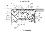
- This hub bearing 1 is an outer ring rotation type, and the inner ring is fixed to a stationary axle, and the outer ring fixed to the wheel rotates together with the wheel.
- the hub bearing 1 is arranged in a row between the inner ring (inner member) 6 having a hole 2 into which the axle is inserted, the outer ring (outer member) 8 arranged outside the inner ring 6, and the inner ring 6 and the outer ring 8. It has a plurality of balls 10 arranged, a plurality of balls 12 arranged in a row between the inner ring 6 and the outer ring 8, and a plurality of cages 14 and 15 for holding these balls in a fixed position.
- the inner ring 6 is fixed to a stationary axle.
- the outer ring 8 has the role of a hub fixed to the wheel. Therefore, the hub flange 18 is formed on the outer ring 8, and the wheel can be attached to the hub flange 18 by the hub bolt 19. In this way, the outer ring 8 is fixed to the wheel and rotates together with the wheel.
- the outer ring 8 and the hub flange 18 may be formed as separate members and fixed thereto.
- the common center axis Ax of the axle and the hub bearing 1 extends in the vertical direction in FIG. In FIG. 1, only the left side portion with respect to the central axis Ax is shown. Although not shown in detail, the lower side of FIG. 1 is the outer side (outboard side) where the wheels of the automobile are arranged, and the upper side is the inner side (inboard side) where the differential gears and the like are arranged.
- the outside and the inside shown in FIG. 1 mean the outside and the inside in the radial direction, respectively.
- a sealing device 20 for sealing the gap between the outer ring 8 and the inner ring 6 is arranged near the cylindrical end 8A on the inboard side of the outer ring 8.
- the sealing device 20 prevents the outflow of grease, that is, the lubricant from the internal space of the hub bearing 1, and also prevents foreign matter (including water (including muddy water or salt water) and dust) from the outside into the inside of the hub bearing 1. Prevent inflow.
- the arrow F shows an example of the direction of the flow of foreign matter from the outside.
- the sealing device 20 is arranged in the gap between the end portion 8A on the inboard side of the outer ring 8 of the hub bearing 1 and the inner ring 6 of the hub bearing 1.
- the sealing device 20 is annular, only the left side portion thereof is shown in FIG.
- the sealing device 20 has a composite structure including the first sealing member 30 and the second sealing member 40.
- the first seal member 30 is a fixed seal member that is fixed to the stationary inner ring 6 and does not rotate.
- the first sealing member 30 has a composite structure having a rigid ring 31 and an elastic ring 32.
- the rigid ring 31 is made of a rigid material, for example metal.
- the elastic ring 32 is made of an elastic material, for example, an elastomer.
- the rigid ring 31 has a substantially L-shaped cross-sectional shape. Specifically, the rigid ring 31 includes a cylindrical sleeve 31A and an annular flange 31B extending radially outward from the sleeve 31A.
- the sleeve 31A is attached to the inner ring 6. Specifically, the end portion of the inner ring 6 is fitted into the sleeve 31A by a tightening method.
- the flange 31B is a flat plate and is in a plane perpendicular to the axis of the sleeve 31A.
- the flange 31B is arranged on the inboard side of the sleeve 31A.
- the elastic ring 32 is in close contact with the flange 31B of the rigid ring 31. Specifically, the elastic ring 32 covers the entire inboard side surface of the flange 31B, covers the outer edge of the flange 31B, and further covers a part of the outer side of the outboard side surface. Therefore, the elastic ring 32 and the flange 31B can be regarded as forming one flange 33.
- the second seal member 40 is a rotating seal member that is fixed to the rotating outer ring 8 and rotates.
- the second sealing member 40 also has a composite structure having an elastic ring 41 and a rigid ring 42.
- the elastic ring 41 is made of an elastic material, for example, an elastomer.
- the rigid ring 42 is made of a rigid material, for example metal, to reinforce the elastic ring 41.
- the rigid ring 42 has a substantially L-shaped cross-sectional shape. A part of the rigid ring 42 is embedded in the elastic ring 41 and is in close contact with the elastic ring 41.
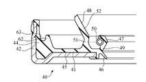
- the second seal member 40 has a tubular portion 44, a disk portion 45, a grease lip (radial lip) 46, a seal lip (radial lip) 47, and a side lip 48.
- the tubular portion 44 is attached to the outer ring 8. Specifically, the tubular portion 44 is fitted into the end portion 8A of the outer ring 8 by a tightening method.
- the tubular portion 44 is composed of an elastic ring 41 and a rigid ring 42.
- the disk portion 45 extends radially inward from the tubular portion 44 and faces the flange 31B of the rigid ring 31 of the first sealing member 30.
- the disk portion 45 is arranged on the outboard side of the tubular portion 44.
- the disk portion 45 is also composed of an elastic ring 41 and a rigid ring 42.
- the grease lip 46 and the seal lip 47 are arranged radially inside the disk portion 45 and slidably contact the sleeve 31A.
- the grease lip 46 and the seal lip 47 are composed of an elastic ring 41.
- Grease is arranged in the space on the outboard side of the disk portion 45 (internal space of the hub bearing 1) between the outer ring 8 and the inner ring 6. This grease reduces the friction between the balls 10, 12, the outer ring 8, and the inner ring 6.
- the grease lip 46 is a truncated cone-shaped thin plate extending radially inward and diagonally toward the outboard side from the elastic portion at the radial inner end of the disk portion 45.
- the tip of the grease lip 46 comes into contact with the outer peripheral surface of the sleeve 31A.
- the grease lip 46 prevents grease from flowing out from the internal space of the hub bearing 1 to the inboard side.
- the seal lip 47 is a ridge formed on the annular portion 49 extending from the elastic portion at the radial inner end of the disc portion 45 toward the inboard side.
- the annular portion 49 is also composed of the elastic ring 41. As shown in FIG. 3, in the initial state where the first sealing member 30 and the second sealing member 40 are not combined, this ridge has a triangular cross section.
- the seal lip 47 contacts the outer peripheral surface of the sleeve 31A and backs up the grease lip 46. That is, the outflow of grease that has passed through the grease lip 46 from the outboard side to the inboard side is prevented.
- a garter spring 50 is wound around the outer circumference of the annulus 49.
- the garter spring 50 applies a radial inward compressive force to the seal lip 47 to increase the binding force of the seal lip 47 to the sleeve 31A.
- the side lip 48 is a thin plate extending from the elastic portion of the disk portion 45 toward the flange 31B.
- the side lip 48 is composed of an elastic ring 41.
- the side lip 48 has a base portion 51 adjacent to the disk portion 45, and a tip portion 52 having a truncated cone shape extending radially outward from the base portion 51 and diagonally toward the flange 31B.
- the tip 52 of the side lip 48 slidably contacts the flange 31B.
- the tubular portion 44 is arranged on the radial outside of the flange 33 of the first sealing member 30, that is, on the outer side of the elastic portion in close contact with the outer end edge of the flange 31B of the rigid ring 31.
- An annular gap 54 is provided between the tubular portion 44 and the flange 33. Foreign matter can enter the space 55 between the flange 33 of the first sealing member 30 and the disk portion 45 of the second sealing member 40 from the outside of the hub bearing 1 through the gap 54. On the contrary, foreign matter may be discharged from the space 55 to the outside through the gap 54.
- the side lip 48 comes into contact with the flange 31B and has a role of preventing foreign matter that has entered the space 55 from further entering toward the seal lip 47.
- the side lip 48 has a very large length as compared with the distance between the disc portion 45 on which the side lip 48 protrudes and the flange 33. This is because the second seal member 40 rotates together with the outer ring 8, so that a centrifugal force is applied to the side lip 48. Since the side lip 48 should maintain contact with the flange 31B even when centrifugal force is applied, the side lip 48 is designed to have a large length in order to increase the contact pressure of the side lip 48 with the flange 31B. ..
- the side lip 48 is coated with grease in order to reduce the torque applied from the flange 31B to the second sealing member 40.
- This grease is typically different from the grease that lubricates the balls 10, 12, the outer ring 8, and the inner ring 6.
- the first sealing member 30 is provided with an annular first protrusion 60 that receives the grease splashed by the side lip 48.
- the first protrusion 60 projects from the elastic portion of the flange 33 toward the disk portion 45 of the second sealing member 40. Therefore, in this embodiment, the first protrusion 60 is composed of the elastic ring 32.
- the first protrusion 60 is arranged radially outside the side lip 48 and overlaps the side lip 48 in the radial direction.
- the first protrusion 60 reduces the discharge of grease by centrifugal force from the space 55 between the flange 33 and the disk portion 45. Since the grease in the space 55 reduces the wear of the side lip 48, the life of the side lip 48 is improved by holding the grease in the space 55.
- the second seal member 40 has an annular second protrusion 62 that protrudes from the elastic portion of the disk portion 45 toward the flange 33 of the first seal member 30.
- the second protrusion 62 is composed of an elastic ring 41.
- the second protrusion 62 is arranged radially outside the first protrusion 60 and overlaps the first protrusion 60 in the radial direction.
- a peripheral groove 63 that is relatively recessed in the second protrusion 62 is formed.
- the second protrusion 62 formed on the second seal member 40 is arranged on the outside of the first protrusion 60, foreign matter enters the space 55 between the flange 33 and the disk portion 45 from the outside. It's hard to do. Even if a foreign substance enters the peripheral groove 63, the second sealing member 40 is attached to the rotating outer ring 8, so that the second protrusion 62 of the second sealing member 40 can bounce the foreign substance. ..
- the inner peripheral surface 62a of the annular second projection 62 is inclined and has a diameter that increases toward the flange 33 of the first sealing member 30. Therefore, even if a foreign substance enters the space 55, the foreign substance is likely to be discharged along the inner peripheral surface 62a of the second protrusion 62.
- the outer peripheral surface 60a of the first protrusion 60 facing the inner peripheral surface 62a of the second protrusion 62 is also inclined and has a diameter that increases toward the flange 33 of the first sealing member 30. Therefore, the outer peripheral surface 60a does not block the flow of foreign matter moving along the inner peripheral surface 62a.
- FIGS. 4 and 5 relate to a second embodiment of the present invention.
- the same reference numerals are used to indicate the components already described, and these components will not be described in detail.
- the tip end portion 52 of the side lip 48 has a first portion 52a located on the base portion 51 side and a second portion located on the side opposite to the base portion 51. It has part 52b of 2.
- the second sealing device 20 with respect to the axial direction is used in the initial state where the first sealing member 30 and the second sealing member 40A are not combined (force is not applied to the side lip 48).
- the tilt angle ⁇ of the portion 52b is smaller than the tilt angle ⁇ of the first portion 52a with respect to the axial direction of the sealing device 20. That is, the tip portion 52 of the side lip 48 has two truncated cone-shaped portions 52a and 52b, and the most advanced second portion 52b is closer to a cylinder than the first portion 52a.
- the first sealing member 30 and the second sealing member 40A are combined, thanks to the shapes of the first portion 52a and the second portion 52b of the tip portion 52 of the side lip 48 in the initial state.
- the tip portion 52 of the side lip 48 is composed of a single truncated cone-shaped portion in the initial state.
- FIG. 2 when the first sealing member 30 and the second sealing member 40 are combined and the side lip 48 of the second sealing member 40 is brought into contact with the flange 33 of the first sealing member 30. , A very wide area CA of the tip 52 of the side lip 48 is brought into contact with the flange 33.
- the second embodiment can reduce the torque applied from the flange 33 to the second seal member 40 as compared with the first embodiment. This effect is more exerted when the outer ring 8 and thus the second seal member 40 rotates at a low speed. This is because when the second sealing member 40 rotates at high speed, the centrifugal force applied to the side lip 48 becomes stronger, and the contact region CA between the side lip 48 and the flange 33 also becomes smaller in the first embodiment. ..
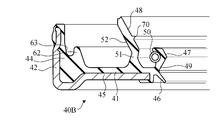
- FIGS. 6 and 7 relate to a third embodiment of the present invention.
- the side lip 48 has an annular raised portion 70 in addition to the base portion 51 and the tip portion 52.
- the raised portion 70 is formed as a continuous ring on the surface of the tip portion 52 facing the flange 33.
- the raised portion 70 has a triangular cross section.
- the first seal member 30 and the second seal member 40 are combined, and the side lip 48 of the second seal member 40 is the first.
- a very wide area CA of the tip 52 of the side lip 48 is brought into contact with the flange 33.
- the region where the tip end portion 52 of the side lip 48 contacts the flange 33 is reduced as compared with the first embodiment, and the torque applied from the flange 33 to the second sealing member 40B is reduced. ..
- This effect is more exerted when the outer ring 8 and thus the second seal member 40 rotates at a low speed. This is because when the second sealing member 40 rotates at high speed, the centrifugal force applied to the side lip 48 becomes stronger, and the contact region CA between the side lip 48 and the flange 33 also becomes smaller in the first embodiment. ..
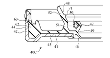
- FIG. 8 shows the second sealing member 40C of the sealing device according to the modified example of the third embodiment.
- the side lip 48 has a raised portion 71 having a semi-circular cross section instead of the raised portion 70 having a triangular cross section.
- the cross-sectional shape of the raised portion formed on the side lip 48 in the initial state is not limited.
- the first protrusion 60 of the first seal member 30 is formed on the elastic ring 32.
- a first protrusion 61 is formed on the rigid ring 31 so as to protrude from the outer edge of the flange 31B toward the disk portion 45 of the second seal member 40. May be good.
- the first protrusion 61 is arranged radially outside the side lip 48 and overlaps the side lip 48 in the radial direction. The first protrusion 61 reduces the discharge of grease by centrifugal force from the space 55 between the flange 33 and the disk portion 45.
- the outer peripheral surface 61a of the first protrusion 61 is inclined and has a diameter that increases toward the flange 33 of the first sealing member 30.
- the modified example of FIG. 9 is a modified example of the first embodiment, but in other embodiments, the first protrusion 61 formed of a rigid material may be provided.
- a sealing device that is placed between a fixed inner member and a rotating outer member and seals a gap between the inner member and the outer member.
- a sleeve attached to the inner member and a first sealing member having a flange extending radially outward from the sleeve.
- a tubular portion arranged on the radial outer side of the flange and attached to the outer member, a disk portion extending radially inward from the tubular portion and facing the flange, and a disk portion arranged on the radial inner side of the disk portion.
- the first sealing member has an annular first protrusion protruding from the flange toward the disk portion of the second sealing member, and the first protrusion is in the radial direction of the side lip. Arranged on the outside, it overlaps with the side lip in the radial direction.
- the second sealing member has an annular second protrusion protruding from the disk portion toward the flange of the first sealing member, and the second protrusion has a diameter of the first protrusion.
- a sealing device arranged on the outside in the direction and overlapping with the first protrusion in the radial direction.
- Clause 2 The sealing device according to Clause 1, wherein the second protrusion has an inner peripheral surface whose diameter increases toward the flange of the first sealing member.
- the side lip has a base portion adjacent to the disk portion and a tip portion having a truncated cone shape extending radially outward from the base portion and diagonally extending toward the flange.
- the tip portion of the sealing device has a first portion located on the base side and a second portion located on the opposite side of the base, and in an initial state where no force is applied to the side lip.
- the sealing device according to Clause 1 or 2 wherein the inclination angle of the second portion with respect to the axial direction is smaller than the inclination angle of the first portion with respect to the axial direction of the sealing device.
- the first sealing member and the second sealing member are combined to form the second sealing member.
- the side lip of the first seal member is brought into contact with the flange of the first sealing member, only a narrow area at the tip of the side lip is brought into contact with the flange. Therefore, the torque applied from the flange to the second sealing member is reduced.
- the side lip faces a base portion adjacent to the disk portion, a tip portion radially outward from the base portion and diagonally extending toward the flange and having a truncated cone shape, and the tip portion of the tip portion facing the flange.
- the sealing device according to Clause 1 or 2 characterized in that it has an annular ridge formed on a surface.
- the first sealing member and the second sealing member are combined and the side lip of the second sealing member is brought into contact with the flange of the first sealing member, it is formed at the tip of the side lip.
- the formed annular ridge contacts the flange. Therefore, the region where the tip end portion of the side lip contacts the flange is reduced, and the torque applied from the flange to the second sealing member is reduced.
Abstract
This sealing device includes a first seal member and a second seal member. The first seal member includes a sleeve attached to an inside member, and a flange. The second seal member includes a tubular part attached to an outside member, a disc part facing the flange, a radial lip that slidably contacts the sleeve, and a side lip that extends from the disc part toward the flange and slidably contacts the flange. The first seal member includes a first protrusion having a ring shape and protruding from the flange toward the disc part of the second seal member. The first protrusion is disposed on a radially outer side of the side lip, and overlaps the side lip in the radial direction. The second seal member includes a second protrusion having a ring shape and protruding from the disc part toward the flange of the first seal member. The second protrusion is disposed on a radially outer side of the first protrusion, and overlaps the first protrusion in the radial direction.
Description
本発明は、密封装置に関する。
The present invention relates to a sealing device.
自動車のハブには、車軸を支持する転がり軸受が設けられる。この転がり軸受をハブベアリングと呼ぶ。ハブベアリングの内輪と外輪の間には密封装置が設けられる。この密封装置は、軸受内部の潤滑剤(グリース)を密封するとともに、外部から水やダスト等の異物が軸受内部へ侵入しないように阻止する。
The hub of an automobile is provided with rolling bearings that support the axle. This rolling bearing is called a hub bearing. A sealing device is provided between the inner ring and the outer ring of the hub bearing. This sealing device seals the lubricant (grease) inside the bearing and prevents foreign substances such as water and dust from entering the inside of the bearing from the outside.
ハブベアリングには、内輪回転型と外輪回転型がある(特許文献1)。内輪回転型は、外輪が車体に固定されており、車軸に固定される内輪とハブが車軸とともに回転するタイプである。このタイプは、車輪が車軸とともに回転するので、車輪が駆動輪である場合にも、車輪が従動輪である場合にも使用される。外輪回転型は、静止した車軸に内輪が固定され、車輪に固定される外輪が車輪とともに回転するタイプである。このタイプは、車軸が静止しているので、車輪が従動輪である場合に使用される。
There are two types of hub bearings: inner ring rotation type and outer ring rotation type (Patent Document 1). The inner ring rotation type is a type in which the outer ring is fixed to the vehicle body, and the inner ring and the hub fixed to the axle rotate together with the axle. This type is used both when the wheels are driving wheels and when the wheels are driven wheels, as the wheels rotate with the axle. The outer ring rotation type is a type in which the inner ring is fixed to a stationary axle and the outer ring fixed to the wheel rotates together with the wheel. This type is used when the wheels are driven wheels because the axles are stationary.
ハブベアリングに設けられる密封装置は、外側部材である外輪に固定されるシール部材と、内側部材である内輪に固定されるもう1つのシール部材を有するものがある。これらのシール部材は、互いに摺動可能に接触させられる。
Some sealing devices provided on the hub bearing have a sealing member fixed to the outer ring, which is an outer member, and another sealing member fixed to the inner ring, which is an inner member. These sealing members are slidably contacted with each other.
外輪回転型のハブベアリングに使用される密封装置においては、外輪に固定されるシール部材に遠心力がかかる。遠心力がかかってもシール部材の間の接触を維持するには、両者間の接触圧を高めるべきである。このような環境でも密封装置の寿命が長いことが望ましい。
In the sealing device used for the outer ring rotary type hub bearing, centrifugal force is applied to the sealing member fixed to the outer ring. In order to maintain the contact between the sealing members even when centrifugal force is applied, the contact pressure between the two should be increased. Even in such an environment, it is desirable that the sealing device has a long life.
また、水(泥水または塩水を含む)の多い環境で使用される場合には、水が密封対象(例えば軸受)の内部に侵入しないことが望ましい。
Also, when used in an environment with a lot of water (including muddy water or salt water), it is desirable that water does not enter the inside of the sealed object (for example, bearing).
そこで、本発明は、寿命が高く、異物からの保護性能が高い密封装置を提供する。
Therefore, the present invention provides a sealing device having a long life and high protection performance from foreign substances.
本発明のある態様に係る密封装置は、固定された内側部材と回転する外側部材との間に配置され、前記内側部材と前記外側部材との間の間隙を封止する。密封装置は、前記内側部材に取り付けられたスリーブと、前記スリーブから径方向外側に広がるフランジを有する第1のシール部材と、前記フランジの径方向外側に配置されて前記外側部材に取り付けられた管状部と、前記管状部から径方向内側に広がり前記フランジに対向する円板部と、前記円板部の径方向内側に配置されて前記スリーブに摺動可能に接触するラジアルリップと、前記円板部から前記フランジに向けて延びて前記フランジに摺動可能に接触するサイドリップを有する第2のシール部材を有する。前記第1のシール部材は、前記フランジから前記第2のシール部材の前記円板部に向けて突出する環状の第1の突起を有し、前記第1の突起は、前記サイドリップの径方向外側に配置されて、前記サイドリップと径方向において重なっている。前記第2のシール部材は、前記円板部から前記第1のシール部材の前記フランジに向けて突出する環状の第2の突起を有し、前記第2の突起は前記第1の突起の径方向外側に配置されて、前記第1の突起と径方向において重なっている。
The sealing device according to an aspect of the present invention is arranged between a fixed inner member and a rotating outer member, and seals a gap between the inner member and the outer member. The sealing device includes a sleeve attached to the inner member, a first sealing member having a flange extending radially outward from the sleeve, and a tubular arranged radially outward of the flange and attached to the outer member. A disk portion extending radially inward from the tubular portion and facing the flange, a radial lip arranged radially inward of the disk portion and slidably contacting the sleeve, and the disk portion. It has a second sealing member having a side lip that extends from the portion towards the flange and slidably contacts the flange. The first sealing member has an annular first protrusion protruding from the flange toward the disk portion of the second sealing member, and the first protrusion is in the radial direction of the side lip. It is arranged on the outside and overlaps with the side lip in the radial direction. The second sealing member has an annular second protrusion protruding from the disk portion toward the flange of the first sealing member, and the second protrusion has a diameter of the first protrusion. It is arranged outside the direction and overlaps with the first protrusion in the radial direction.
この態様によれば、第1のシール部材に形成された第1の突起が、第1のシール部材のフランジと第2のシール部材の円板部の間の空間からグリースが遠心力で排出されることを低減する。この空間内のグリースはサイドリップの摩耗を低減させるので、グリースが空間内に保持されることによりサイドリップの寿命が向上する。また、第2のシール部材に形成された第2の突起が、第1の突起の外側に配置されているので、外部からフランジと円板部の間の空間内に異物が侵入しにくい。第2のシール部材は回転する外側部材に取り付けられているので、第2のシール部材の第2の突起は、異物を跳ね飛ばすことができる。
According to this aspect, the grease is discharged by centrifugal force from the space between the flange of the first sealing member and the disk portion of the second sealing member of the first protrusion formed on the first sealing member. To reduce that. Since the grease in this space reduces the wear of the side lip, the life of the side lip is improved by holding the grease in the space. Further, since the second protrusion formed on the second seal member is arranged on the outside of the first protrusion, it is difficult for foreign matter to enter the space between the flange and the disk portion from the outside. Since the second sealing member is attached to the rotating outer member, the second protrusion of the second sealing member can bounce off foreign matter.
以下、添付の図面を参照しながら本発明に係る様々な実施形態を説明する。図面の縮尺は必ずしも正確ではなく、一部の特徴は誇張または省略されることもある。
Hereinafter, various embodiments according to the present invention will be described with reference to the accompanying drawings. Drawing scales are not always accurate and some features may be exaggerated or omitted.
図1は、本発明の各実施形態に係る密封装置が使用される転がり軸受の一例である自動車用のハブベアリングを示す。但し、本発明の用途はハブベアリングには限定されず、他の転がり軸受にも本発明は適用可能である。また、以下の説明では、ハブベアリングは、玉軸受であるが、本発明の用途は玉軸受には限定されず、他の種類の転動体を有する、ころ軸受、針軸受などの他の転がり軸受にも本発明は適用可能である。また、自動車以外の機械に使用される転がり軸受にも本発明は適用可能である。
FIG. 1 shows a hub bearing for an automobile, which is an example of a rolling bearing in which the sealing device according to each embodiment of the present invention is used. However, the application of the present invention is not limited to hub bearings, and the present invention can be applied to other rolling bearings. Further, in the following description, the hub bearing is a ball bearing, but the application of the present invention is not limited to the ball bearing, and other rolling bearings such as roller bearings and needle bearings having other types of rolling elements. The present invention is also applicable. The present invention is also applicable to rolling bearings used in machines other than automobiles.
このハブベアリング1は、外輪回転型であり、静止した車軸に内輪が固定され、車輪に固定される外輪が車輪とともに回転する。ハブベアリング1は、車軸が挿入される孔2を有する内輪(内側部材)6と、内輪6の外側に配置された外輪(外側部材)8と、内輪6と外輪8の間に1列に配置された複数の玉10と、内輪6と外輪8の間に1列に配置された複数の玉12と、これらの玉を定位置に保持する複数の保持器14,15を有する。
This hub bearing 1 is an outer ring rotation type, and the inner ring is fixed to a stationary axle, and the outer ring fixed to the wheel rotates together with the wheel. The hub bearing 1 is arranged in a row between the inner ring (inner member) 6 having a hole 2 into which the axle is inserted, the outer ring (outer member) 8 arranged outside the inner ring 6, and the inner ring 6 and the outer ring 8. It has a plurality of balls 10 arranged, a plurality of balls 12 arranged in a row between the inner ring 6 and the outer ring 8, and a plurality of cages 14 and 15 for holding these balls in a fixed position.
内輪6は静止した車軸に固定されている。外輪8は、車輪に固定されるハブの役割を有する。したがって、外輪8には、ハブフランジ18が形成されおり、ハブフランジ18には、ハブボルト19によって、車輪を取り付けることができる。このように、外輪8は、車輪に固定されて車輪とともに回転する。但し、外輪8とハブフランジ18を別個の部材として形成し、これらを固定してもよい。
The inner ring 6 is fixed to a stationary axle. The outer ring 8 has the role of a hub fixed to the wheel. Therefore, the hub flange 18 is formed on the outer ring 8, and the wheel can be attached to the hub flange 18 by the hub bolt 19. In this way, the outer ring 8 is fixed to the wheel and rotates together with the wheel. However, the outer ring 8 and the hub flange 18 may be formed as separate members and fixed thereto.
車軸およびハブベアリング1の共通の中心軸線Axは、図1の上下方向に延びている。図1においては、中心軸線Axに対する左側部分のみが示されている。詳細には図示しないが、図1の下側は自動車の車輪が配置される外側(アウトボード側)であり、上側は差動歯車などが配置される内側(インボード側)である。図1に示した外側、内側は、それぞれ径方向の外側、内側を意味する。
The common center axis Ax of the axle and the hub bearing 1 extends in the vertical direction in FIG. In FIG. 1, only the left side portion with respect to the central axis Ax is shown. Although not shown in detail, the lower side of FIG. 1 is the outer side (outboard side) where the wheels of the automobile are arranged, and the upper side is the inner side (inboard side) where the differential gears and the like are arranged. The outside and the inside shown in FIG. 1 mean the outside and the inside in the radial direction, respectively.
外輪8のインボード側の円筒状の端部8Aの付近には、外輪8と内輪6の間の間隙を封止する密封装置20が配置されている。密封装置20は、ハブベアリング1の内部空間からのグリース、すなわち潤滑剤の流出を防止するとともに、外部からハブベアリング1の内部への異物(水(泥水または塩水を含む)およびダストを含む)の流入を防止する。図1において、矢印Fは、外部からの異物の流れの方向の例を示す。
A sealing device 20 for sealing the gap between the outer ring 8 and the inner ring 6 is arranged near the cylindrical end 8A on the inboard side of the outer ring 8. The sealing device 20 prevents the outflow of grease, that is, the lubricant from the internal space of the hub bearing 1, and also prevents foreign matter (including water (including muddy water or salt water) and dust) from the outside into the inside of the hub bearing 1. Prevent inflow. In FIG. 1, the arrow F shows an example of the direction of the flow of foreign matter from the outside.
第1実施形態
図2に示すように、密封装置20は、ハブ軸受1の外輪8のインボード側の端部8Aと、ハブ軸受1の内輪6との間隙内に配置される。密封装置20は環状であるが、図2においては、その左側部分のみが示されている。図2から明らかなように、密封装置20は、第1のシール部材30と第2のシール部材40を備える複合構造を有する。 First Embodiment As shown in FIG. 2, thesealing device 20 is arranged in the gap between the end portion 8A on the inboard side of the outer ring 8 of the hub bearing 1 and the inner ring 6 of the hub bearing 1. Although the sealing device 20 is annular, only the left side portion thereof is shown in FIG. As is clear from FIG. 2, the sealing device 20 has a composite structure including the first sealing member 30 and the second sealing member 40.
図2に示すように、密封装置20は、ハブ軸受1の外輪8のインボード側の端部8Aと、ハブ軸受1の内輪6との間隙内に配置される。密封装置20は環状であるが、図2においては、その左側部分のみが示されている。図2から明らかなように、密封装置20は、第1のシール部材30と第2のシール部材40を備える複合構造を有する。 First Embodiment As shown in FIG. 2, the
第1のシール部材30は、静止した内輪6に固定され、回転しない固定シール部材である。第1のシール部材30は、剛性環31と弾性環32を有する複合構造である。剛性環31は、剛性材料、例えば金属から形成されている。弾性環32は、弾性材料、例えばエラストマーで形成されている。
The first seal member 30 is a fixed seal member that is fixed to the stationary inner ring 6 and does not rotate. The first sealing member 30 has a composite structure having a rigid ring 31 and an elastic ring 32. The rigid ring 31 is made of a rigid material, for example metal. The elastic ring 32 is made of an elastic material, for example, an elastomer.
剛性環31は、ほぼL字形の断面形状を有する。具体的には、剛性環31は、円筒状のスリーブ31Aと、スリーブ31Aから径方向外側に広がる円環状のフランジ31Bを備える。スリーブ31Aは内輪6に取り付けられる。具体的には、スリーブ31Aには、内輪6の端部が締まり嵌め方式で嵌め入れられる。フランジ31Bは平板であり、スリーブ31Aの軸線に対して垂直な平面内にある。フランジ31Bはスリーブ31Aのインボード側に配置されている。
The rigid ring 31 has a substantially L-shaped cross-sectional shape. Specifically, the rigid ring 31 includes a cylindrical sleeve 31A and an annular flange 31B extending radially outward from the sleeve 31A. The sleeve 31A is attached to the inner ring 6. Specifically, the end portion of the inner ring 6 is fitted into the sleeve 31A by a tightening method. The flange 31B is a flat plate and is in a plane perpendicular to the axis of the sleeve 31A. The flange 31B is arranged on the inboard side of the sleeve 31A.
弾性環32は、剛性環31のフランジ31Bに密着している。具体的には、弾性環32は、フランジ31Bのインボード側の面の全体を覆い、フランジ31Bの外端縁を覆い、さらにアウトボード側の面の外側の一部を覆う。したがって、弾性環32とフランジ31Bが、1つのフランジ33を構成するとみなすことができる。
The elastic ring 32 is in close contact with the flange 31B of the rigid ring 31. Specifically, the elastic ring 32 covers the entire inboard side surface of the flange 31B, covers the outer edge of the flange 31B, and further covers a part of the outer side of the outboard side surface. Therefore, the elastic ring 32 and the flange 31B can be regarded as forming one flange 33.
第2のシール部材40は、回転する外輪8に固定され、回転する回転シール部材である。第2のシール部材40も、弾性環41および剛性環42を有する複合構造である。弾性環41は、弾性材料、例えばエラストマーで形成されている。剛性環42は、剛性材料、例えば金属から形成されており、弾性環41を補強する。剛性環42は、ほぼL字形の断面形状を有する。剛性環42の一部は、弾性環41に埋設されており、弾性環41に密着している。
The second seal member 40 is a rotating seal member that is fixed to the rotating outer ring 8 and rotates. The second sealing member 40 also has a composite structure having an elastic ring 41 and a rigid ring 42. The elastic ring 41 is made of an elastic material, for example, an elastomer. The rigid ring 42 is made of a rigid material, for example metal, to reinforce the elastic ring 41. The rigid ring 42 has a substantially L-shaped cross-sectional shape. A part of the rigid ring 42 is embedded in the elastic ring 41 and is in close contact with the elastic ring 41.
第2のシール部材40は、管状部44、円板部45、グリースリップ(ラジアルリップ)46、シールリップ(ラジアルリップ)47およびサイドリップ48を有する。
The second seal member 40 has a tubular portion 44, a disk portion 45, a grease lip (radial lip) 46, a seal lip (radial lip) 47, and a side lip 48.
管状部44は外輪8に取り付けられる。具体的には、管状部44は外輪8の端部8Aに締まり嵌め方式で嵌め入れられる。管状部44は、弾性環41と剛性環42から構成されている。
The tubular portion 44 is attached to the outer ring 8. Specifically, the tubular portion 44 is fitted into the end portion 8A of the outer ring 8 by a tightening method. The tubular portion 44 is composed of an elastic ring 41 and a rigid ring 42.
円板部45は、管状部44から径方向内側に広がり、第1のシール部材30の剛性環31のフランジ31Bに対向する。円板部45は管状部44のアウトボード側に配置されている。円板部45も、弾性環41と剛性環42から構成されている。
The disk portion 45 extends radially inward from the tubular portion 44 and faces the flange 31B of the rigid ring 31 of the first sealing member 30. The disk portion 45 is arranged on the outboard side of the tubular portion 44. The disk portion 45 is also composed of an elastic ring 41 and a rigid ring 42.
グリースリップ46とシールリップ47は、円板部45の径方向内側に配置されてスリーブ31Aに摺動可能に接触する。グリースリップ46とシールリップ47は、弾性環41から構成されている。
The grease lip 46 and the seal lip 47 are arranged radially inside the disk portion 45 and slidably contact the sleeve 31A. The grease lip 46 and the seal lip 47 are composed of an elastic ring 41.
外輪8と内輪6の間において、円板部45のアウトボード側の空間(ハブベアリング1の内部空間)には、グリースが配置されている。このグリースは、玉10,12、外輪8、内輪6の相互の摩擦を低減させる。
Grease is arranged in the space on the outboard side of the disk portion 45 (internal space of the hub bearing 1) between the outer ring 8 and the inner ring 6. This grease reduces the friction between the balls 10, 12, the outer ring 8, and the inner ring 6.
グリースリップ46は、円板部45の径方向内端の弾性部分から径方向内側かつアウトボード側に向けて斜めに延びる、円錐台形状の薄板である。グリースリップ46の先端はスリーブ31Aの外周面に接触する。グリースリップ46は、ハブベアリング1の内部空間からインボード側へのグリースの流出を阻止する。
The grease lip 46 is a truncated cone-shaped thin plate extending radially inward and diagonally toward the outboard side from the elastic portion at the radial inner end of the disk portion 45. The tip of the grease lip 46 comes into contact with the outer peripheral surface of the sleeve 31A. The grease lip 46 prevents grease from flowing out from the internal space of the hub bearing 1 to the inboard side.
シールリップ47は、円板部45の径方向内端の弾性部分からインボード側に向けて延びる円環部49に形成された隆起である。円環部49も弾性環41から構成されている。図3に示すように、第1のシール部材30と第2のシール部材40が組み合わせられない初期状態では、この隆起は三角形の断面を有する。シールリップ47は、スリーブ31Aの外周面に接触し、グリースリップ46をバックアップする。すなわち、アウトボード側からグリースリップ46を通過したグリースのインボード側への流出を阻止する。
The seal lip 47 is a ridge formed on the annular portion 49 extending from the elastic portion at the radial inner end of the disc portion 45 toward the inboard side. The annular portion 49 is also composed of the elastic ring 41. As shown in FIG. 3, in the initial state where the first sealing member 30 and the second sealing member 40 are not combined, this ridge has a triangular cross section. The seal lip 47 contacts the outer peripheral surface of the sleeve 31A and backs up the grease lip 46. That is, the outflow of grease that has passed through the grease lip 46 from the outboard side to the inboard side is prevented.
円環部49の外周にはガータースプリング50が巻かれている。ガータースプリング50は、シールリップ47に径方向内側への圧縮力を与え、スリーブ31Aに対するシールリップ47の緊縛力を高める。
A garter spring 50 is wound around the outer circumference of the annulus 49. The garter spring 50 applies a radial inward compressive force to the seal lip 47 to increase the binding force of the seal lip 47 to the sleeve 31A.
サイドリップ48は、円板部45の弾性部分からフランジ31Bに向けて延びる薄板である。サイドリップ48は弾性環41から構成されている。サイドリップ48は、円板部45に隣接する基部51と、基部51から径方向外側かつフランジ31Bに向けて斜めに延びて円錐台形状を有する先端部52を有する。サイドリップ48の先端部52は、フランジ31Bに摺動可能に接触する。
The side lip 48 is a thin plate extending from the elastic portion of the disk portion 45 toward the flange 31B. The side lip 48 is composed of an elastic ring 41. The side lip 48 has a base portion 51 adjacent to the disk portion 45, and a tip portion 52 having a truncated cone shape extending radially outward from the base portion 51 and diagonally toward the flange 31B. The tip 52 of the side lip 48 slidably contacts the flange 31B.
管状部44は、第1のシール部材30のフランジ33の径方向外側、つまり剛性環31のフランジ31Bの外端縁に密着する弾性部分のさらに外側に配置されている。管状部44とフランジ33の間には、環状の間隙54が設けられている。ハブベアリング1の外部から間隙54を通じて、第1のシール部材30のフランジ33と第2のシール部材40の円板部45の間の空間55に異物が侵入しうる。逆に、異物が空間55から間隙54を通じて外部に排出されることもありうる。
The tubular portion 44 is arranged on the radial outside of the flange 33 of the first sealing member 30, that is, on the outer side of the elastic portion in close contact with the outer end edge of the flange 31B of the rigid ring 31. An annular gap 54 is provided between the tubular portion 44 and the flange 33. Foreign matter can enter the space 55 between the flange 33 of the first sealing member 30 and the disk portion 45 of the second sealing member 40 from the outside of the hub bearing 1 through the gap 54. On the contrary, foreign matter may be discharged from the space 55 to the outside through the gap 54.
サイドリップ48は、フランジ31Bに接触し、空間55に侵入した異物がシールリップ47に向けてさらに侵入しないように阻止する役割を有する。サイドリップ48が突出する円板部45とフランジ33の間の間隔に比べて、サイドリップ48は非常に大きい長さを有する。これは、第2のシール部材40が外輪8とともに回転するので、サイドリップ48に遠心力がかかるためである。遠心力がかかっても、サイドリップ48はフランジ31Bに接触を維持するべきなので、フランジ31Bへのサイドリップ48の接触圧を高めるために、サイドリップ48は大きい長さを有するよう設計されている。サイドリップ48とフランジ31Bの間の接触圧が高くても、フランジ31Bから第2のシール部材40に与えられるトルクを低減するため、サイドリップ48にはグリースがコートされている。このグリースは、典型的には玉10,12、外輪8、内輪6を潤滑するグリースとは別種である。
The side lip 48 comes into contact with the flange 31B and has a role of preventing foreign matter that has entered the space 55 from further entering toward the seal lip 47. The side lip 48 has a very large length as compared with the distance between the disc portion 45 on which the side lip 48 protrudes and the flange 33. This is because the second seal member 40 rotates together with the outer ring 8, so that a centrifugal force is applied to the side lip 48. Since the side lip 48 should maintain contact with the flange 31B even when centrifugal force is applied, the side lip 48 is designed to have a large length in order to increase the contact pressure of the side lip 48 with the flange 31B. .. Even if the contact pressure between the side lip 48 and the flange 31B is high, the side lip 48 is coated with grease in order to reduce the torque applied from the flange 31B to the second sealing member 40. This grease is typically different from the grease that lubricates the balls 10, 12, the outer ring 8, and the inner ring 6.
しかし、サイドリップ48には遠心力がかかるので、サイドリップ48の周りのグリースが跳ね飛ばされる。そこで、第1のシール部材30には、サイドリップ48に跳ね飛ばされたグリースを受け止める環状の第1の突起60が設けられている。第1の突起60は、フランジ33の弾性部分から第2のシール部材40の円板部45に向けて突出する。したがって、この実施形態では第1の突起60は弾性環32から構成されている。第1の突起60は、サイドリップ48の径方向外側に配置されて、サイドリップ48と径方向において重なっている。第1の突起60は、フランジ33と円板部45の間の空間55からグリースが遠心力で排出されることを低減する。この空間55内のグリースはサイドリップ48の摩耗を低減させるので、グリースが空間55内に保持されることによりサイドリップ48の寿命が向上する。
However, since centrifugal force is applied to the side lip 48, the grease around the side lip 48 is splashed off. Therefore, the first sealing member 30 is provided with an annular first protrusion 60 that receives the grease splashed by the side lip 48. The first protrusion 60 projects from the elastic portion of the flange 33 toward the disk portion 45 of the second sealing member 40. Therefore, in this embodiment, the first protrusion 60 is composed of the elastic ring 32. The first protrusion 60 is arranged radially outside the side lip 48 and overlaps the side lip 48 in the radial direction. The first protrusion 60 reduces the discharge of grease by centrifugal force from the space 55 between the flange 33 and the disk portion 45. Since the grease in the space 55 reduces the wear of the side lip 48, the life of the side lip 48 is improved by holding the grease in the space 55.
一方、第2のシール部材40は、円板部45の弾性部分から第1のシール部材30のフランジ33に向けて突出する環状の第2の突起62を有する。この実施形態では第2の突起62は弾性環41から構成されている。第2の突起62は第1の突起60の径方向外側に配置されて、第1の突起60と径方向において重なっている。第2の突起62の径方向外側には、第2の突起62に相対的に窪んだ周溝63が形成されている。
On the other hand, the second seal member 40 has an annular second protrusion 62 that protrudes from the elastic portion of the disk portion 45 toward the flange 33 of the first seal member 30. In this embodiment, the second protrusion 62 is composed of an elastic ring 41. The second protrusion 62 is arranged radially outside the first protrusion 60 and overlaps the first protrusion 60 in the radial direction. On the radial outer side of the second protrusion 62, a peripheral groove 63 that is relatively recessed in the second protrusion 62 is formed.
第2のシール部材40に形成された第2の突起62が、第1の突起60の外側に配置されているので、外部からフランジ33と円板部45の間の空間55内に異物が侵入しにくい。周溝63まで異物が侵入したとしても、第2のシール部材40は回転する外輪8に取り付けられているので、第2のシール部材40の第2の突起62は、異物を跳ね飛ばすことができる。
Since the second protrusion 62 formed on the second seal member 40 is arranged on the outside of the first protrusion 60, foreign matter enters the space 55 between the flange 33 and the disk portion 45 from the outside. It's hard to do. Even if a foreign substance enters the peripheral groove 63, the second sealing member 40 is attached to the rotating outer ring 8, so that the second protrusion 62 of the second sealing member 40 can bounce the foreign substance. ..
環状の第2の突起62の内周面62aは、傾斜しており、第1のシール部材30のフランジ33に向かうほど大きくなる直径を有する。したがって、空間55に異物が侵入しても、第2の突起62の内周面62aに沿って異物が排出されやすい。第2の突起62の内周面62aに対向する第1の突起60の外周面60aも、傾斜しており、第1のシール部材30のフランジ33に向かうほど大きくなる直径を有する。したがって、外周面60aは内周面62aに沿って移動する異物の流れを阻止しない。
The inner peripheral surface 62a of the annular second projection 62 is inclined and has a diameter that increases toward the flange 33 of the first sealing member 30. Therefore, even if a foreign substance enters the space 55, the foreign substance is likely to be discharged along the inner peripheral surface 62a of the second protrusion 62. The outer peripheral surface 60a of the first protrusion 60 facing the inner peripheral surface 62a of the second protrusion 62 is also inclined and has a diameter that increases toward the flange 33 of the first sealing member 30. Therefore, the outer peripheral surface 60a does not block the flow of foreign matter moving along the inner peripheral surface 62a.
第2実施形態
図4および図5は本発明の第2実施形態に関する。図4以降の図面において、すでに説明した構成要素を示すため、同一の符号が使用され、それらの構成要素については詳細には説明しない。 Second Embodiment FIGS. 4 and 5 relate to a second embodiment of the present invention. In the drawings after FIG. 4, the same reference numerals are used to indicate the components already described, and these components will not be described in detail.
図4および図5は本発明の第2実施形態に関する。図4以降の図面において、すでに説明した構成要素を示すため、同一の符号が使用され、それらの構成要素については詳細には説明しない。 Second Embodiment FIGS. 4 and 5 relate to a second embodiment of the present invention. In the drawings after FIG. 4, the same reference numerals are used to indicate the components already described, and these components will not be described in detail.
第2実施形態に係る密封装置20の第2のシール部材40Aにおいては、サイドリップ48の先端部52は、基部51側に位置する第1の部分52aと、基部51と反対側に位置する第2の部分52bを有する。
In the second sealing member 40A of the sealing device 20 according to the second embodiment, the tip end portion 52 of the side lip 48 has a first portion 52a located on the base portion 51 side and a second portion located on the side opposite to the base portion 51. It has part 52b of 2.
図5に示すように、第1のシール部材30と第2のシール部材40Aが組み合わせられない(サイドリップ48に力が与えられていない)初期状態で、密封装置20の軸線方向に対する第2の部分52bの傾斜角βは、密封装置20の軸線方向に対する第1の部分52aの傾斜角αより小さい。つまり、サイドリップ48の先端部52は、2つの円錐台状の部分52a,52bを有し、最先端である第2の部分52bが第1の部分52aよりも円筒に近似する。初期状態のサイドリップ48の先端部52の第1の部分52aと第2の部分52bの形状のおかげで、図4に示すように、第1のシール部材30と第2のシール部材40Aが組み合わせられて、第2のシール部材40Aのサイドリップ48が第1のシール部材30のフランジ33に接触させられる時、サイドリップ48の先端部52の狭い領域CAだけがフランジ33に接触させられる。
As shown in FIG. 5, in the initial state where the first sealing member 30 and the second sealing member 40A are not combined (force is not applied to the side lip 48), the second sealing device 20 with respect to the axial direction is used. The tilt angle β of the portion 52b is smaller than the tilt angle α of the first portion 52a with respect to the axial direction of the sealing device 20. That is, the tip portion 52 of the side lip 48 has two truncated cone-shaped portions 52a and 52b, and the most advanced second portion 52b is closer to a cylinder than the first portion 52a. As shown in FIG. 4, the first sealing member 30 and the second sealing member 40A are combined, thanks to the shapes of the first portion 52a and the second portion 52b of the tip portion 52 of the side lip 48 in the initial state. When the side lip 48 of the second sealing member 40A is brought into contact with the flange 33 of the first sealing member 30, only the narrow region CA of the tip 52 of the side lip 48 is brought into contact with the flange 33.
これに対して、第1実施形態においては、図3に示すように、初期状態でサイドリップ48の先端部52は、単一の円錐台状の部分からなる。図2に示すように、第1のシール部材30と第2のシール部材40が組み合わせられて、第2のシール部材40のサイドリップ48が第1のシール部材30のフランジ33に接触させられる時、サイドリップ48の先端部52の非常に広い領域CAがフランジ33に接触させられる。
On the other hand, in the first embodiment, as shown in FIG. 3, the tip portion 52 of the side lip 48 is composed of a single truncated cone-shaped portion in the initial state. As shown in FIG. 2, when the first sealing member 30 and the second sealing member 40 are combined and the side lip 48 of the second sealing member 40 is brought into contact with the flange 33 of the first sealing member 30. , A very wide area CA of the tip 52 of the side lip 48 is brought into contact with the flange 33.
したがって、第2実施形態は、第1実施形態よりも、フランジ33から第2のシール部材40に与えられるトルクを低減することが可能である。この効果は、外輪8ひいては第2のシール部材40が低速で回転する場合に、より発揮される。第2のシール部材40が高速で回転する場合には、サイドリップ48に与えられる遠心力が強まり、第1実施形態においてもサイドリップ48とフランジ33の接触領域CAは小さくなってゆくからである。
Therefore, the second embodiment can reduce the torque applied from the flange 33 to the second seal member 40 as compared with the first embodiment. This effect is more exerted when the outer ring 8 and thus the second seal member 40 rotates at a low speed. This is because when the second sealing member 40 rotates at high speed, the centrifugal force applied to the side lip 48 becomes stronger, and the contact region CA between the side lip 48 and the flange 33 also becomes smaller in the first embodiment. ..
第3実施形態
図6および図7は本発明の第3実施形態に関する。第3実施形態に係る密封装置20の第2のシール部材40Bにおいては、サイドリップ48は、基部51と先端部52に加えて、環状の隆起部70を有する。隆起部70は、先端部52のうちフランジ33に対面する面に、連続的な円環として形成されている。図7に示すように、第1のシール部材30と第2のシール部材40Bが組み合わせられない(サイドリップ48に力が与えられていない)初期状態で、隆起部70は三角形の断面を有する。 Third Embodiment FIGS. 6 and 7 relate to a third embodiment of the present invention. In thesecond sealing member 40B of the sealing device 20 according to the third embodiment, the side lip 48 has an annular raised portion 70 in addition to the base portion 51 and the tip portion 52. The raised portion 70 is formed as a continuous ring on the surface of the tip portion 52 facing the flange 33. As shown in FIG. 7, in the initial state where the first sealing member 30 and the second sealing member 40B are not combined (force is not applied to the side lip 48), the raised portion 70 has a triangular cross section.
図6および図7は本発明の第3実施形態に関する。第3実施形態に係る密封装置20の第2のシール部材40Bにおいては、サイドリップ48は、基部51と先端部52に加えて、環状の隆起部70を有する。隆起部70は、先端部52のうちフランジ33に対面する面に、連続的な円環として形成されている。図7に示すように、第1のシール部材30と第2のシール部材40Bが組み合わせられない(サイドリップ48に力が与えられていない)初期状態で、隆起部70は三角形の断面を有する。 Third Embodiment FIGS. 6 and 7 relate to a third embodiment of the present invention. In the
図6に示すように、第1のシール部材30と第2のシール部材40Bが組み合わせられて第2のシール部材40Bのサイドリップ48が第1のシール部材30のフランジ33に接触させられる時、サイドリップ48の先端部52に形成された環状の隆起部70がフランジ33に接触する。図6では、サイドリップ48の先端部52の最先端部もフランジ33に接触するが、隆起部70の位置およびサイドリップ48に与えられる遠心力によっては、先端部52の最先端部がフランジ33に接触しないこともありうる。
As shown in FIG. 6, when the first sealing member 30 and the second sealing member 40B are combined and the side lip 48 of the second sealing member 40B is brought into contact with the flange 33 of the first sealing member 30. The annular raised portion 70 formed on the tip portion 52 of the side lip 48 comes into contact with the flange 33. In FIG. 6, the tip end portion of the tip portion 52 of the side lip 48 also contacts the flange 33, but the tip end portion of the tip portion 52 is the flange 33 depending on the position of the raised portion 70 and the centrifugal force applied to the side lip 48. It is possible that you will not come in contact with.
これに対して、第1実施形態においては、図2に示すように、第1のシール部材30と第2のシール部材40が組み合わせられて、第2のシール部材40のサイドリップ48が第1のシール部材30のフランジ33に接触させられる時、サイドリップ48の先端部52の非常に広い領域CAがフランジ33に接触させられる。
On the other hand, in the first embodiment, as shown in FIG. 2, the first seal member 30 and the second seal member 40 are combined, and the side lip 48 of the second seal member 40 is the first. When brought into contact with the flange 33 of the seal member 30, a very wide area CA of the tip 52 of the side lip 48 is brought into contact with the flange 33.
したがって、第3実施形態では、第1実施形態よりも、サイドリップ48の先端部52がフランジ33に接触する領域が減少して、フランジ33から第2のシール部材40Bに与えられるトルクが低減する。この効果は、外輪8ひいては第2のシール部材40が低速で回転する場合に、より発揮される。第2のシール部材40が高速で回転する場合には、サイドリップ48に与えられる遠心力が強まり、第1実施形態においてもサイドリップ48とフランジ33の接触領域CAは小さくなってゆくからである。
Therefore, in the third embodiment, the region where the tip end portion 52 of the side lip 48 contacts the flange 33 is reduced as compared with the first embodiment, and the torque applied from the flange 33 to the second sealing member 40B is reduced. .. This effect is more exerted when the outer ring 8 and thus the second seal member 40 rotates at a low speed. This is because when the second sealing member 40 rotates at high speed, the centrifugal force applied to the side lip 48 becomes stronger, and the contact region CA between the side lip 48 and the flange 33 also becomes smaller in the first embodiment. ..
図8は、第3実施形態の変形例に係る密封装置の第2のシール部材40Cを示す。第2のシール部材40Cにおいては、サイドリップ48は、三角形の断面を有する隆起部70の代わりに、半円形の断面を有する隆起部71を有する。このように、サイドリップ48に形成される隆起部の初期状態の断面形状は限定されない。
FIG. 8 shows the second sealing member 40C of the sealing device according to the modified example of the third embodiment. In the second sealing member 40C, the side lip 48 has a raised portion 71 having a semi-circular cross section instead of the raised portion 70 having a triangular cross section. As described above, the cross-sectional shape of the raised portion formed on the side lip 48 in the initial state is not limited.
他の変形例
以上、本発明の好ましい実施形態を参照しながら本発明を図示して説明したが、当業者にとって特許請求の範囲に記載された発明の範囲から逸脱することなく、形式および詳細の変更が可能であることが理解されるであろう。このような変更、改変および修正は本発明の範囲に包含されるはずである。 Other Modifications Although the present invention has been illustrated and described above with reference to preferred embodiments of the present invention, those skilled in the art will not deviate from the scope of the invention described in the claims and will be described in form and detail. It will be understood that changes are possible. Such changes, modifications and modifications should be included within the scope of the invention.
以上、本発明の好ましい実施形態を参照しながら本発明を図示して説明したが、当業者にとって特許請求の範囲に記載された発明の範囲から逸脱することなく、形式および詳細の変更が可能であることが理解されるであろう。このような変更、改変および修正は本発明の範囲に包含されるはずである。 Other Modifications Although the present invention has been illustrated and described above with reference to preferred embodiments of the present invention, those skilled in the art will not deviate from the scope of the invention described in the claims and will be described in form and detail. It will be understood that changes are possible. Such changes, modifications and modifications should be included within the scope of the invention.
例えば、上記の実施形態においては、第1のシール部材30の第1の突起60は、弾性環32に形成されている。しかし、図9に示す変形例のように、剛性環31に、フランジ31Bの外端縁から、第2のシール部材40の円板部45に向けて突出する第1の突起61を形成してもよい。第1の突起61は、サイドリップ48の径方向外側に配置されて、サイドリップ48と径方向において重なっている。第1の突起61は、フランジ33と円板部45の間の空間55からグリースが遠心力で排出されることを低減する。第1の突起61の外周面61aは、傾斜しており、第1のシール部材30のフランジ33に向かうほど大きくなる直径を有する。図9の変形例は、第1実施形態の変形例であるが、他の実施形態において、剛性材料から形成された第1の突起61を設けてもよい。
For example, in the above embodiment, the first protrusion 60 of the first seal member 30 is formed on the elastic ring 32. However, as in the modified example shown in FIG. 9, a first protrusion 61 is formed on the rigid ring 31 so as to protrude from the outer edge of the flange 31B toward the disk portion 45 of the second seal member 40. May be good. The first protrusion 61 is arranged radially outside the side lip 48 and overlaps the side lip 48 in the radial direction. The first protrusion 61 reduces the discharge of grease by centrifugal force from the space 55 between the flange 33 and the disk portion 45. The outer peripheral surface 61a of the first protrusion 61 is inclined and has a diameter that increases toward the flange 33 of the first sealing member 30. The modified example of FIG. 9 is a modified example of the first embodiment, but in other embodiments, the first protrusion 61 formed of a rigid material may be provided.
本発明の態様は、下記の番号付けされた条項にも記載される。
条項1. 固定された内側部材と回転する外側部材との間に配置され、前記内側部材と前記外側部材との間の間隙を封止する密封装置であって、
前記内側部材に取り付けられたスリーブと、前記スリーブから径方向外側に広がるフランジを有する第1のシール部材と、
前記フランジの径方向外側に配置されて前記外側部材に取り付けられた管状部と、前記管状部から径方向内側に広がり前記フランジに対向する円板部と、前記円板部の径方向内側に配置されて前記スリーブに摺動可能に接触するラジアルリップと、前記円板部から前記フランジに向けて延びて前記フランジに摺動可能に接触するサイドリップを有する第2のシール部材を有し、
前記第1のシール部材は、前記フランジから前記第2のシール部材の前記円板部に向けて突出する環状の第1の突起を有し、前記第1の突起は、前記サイドリップの径方向外側に配置されて、前記サイドリップと径方向において重なっており、
前記第2のシール部材は、前記円板部から前記第1のシール部材の前記フランジに向けて突出する環状の第2の突起を有し、前記第2の突起は前記第1の突起の径方向外側に配置されて、前記第1の突起と径方向において重なっている
密封装置。 Aspects of the invention are also described in the numbered clauses below.
Clause 1. A sealing device that is placed between a fixed inner member and a rotating outer member and seals a gap between the inner member and the outer member.
A sleeve attached to the inner member and a first sealing member having a flange extending radially outward from the sleeve.
A tubular portion arranged on the radial outer side of the flange and attached to the outer member, a disk portion extending radially inward from the tubular portion and facing the flange, and a disk portion arranged on the radial inner side of the disk portion. It has a second sealing member having a radial lip that is slidably in contact with the sleeve and a side lip that extends from the disc portion toward the flange and is slidably in contact with the flange.
The first sealing member has an annular first protrusion protruding from the flange toward the disk portion of the second sealing member, and the first protrusion is in the radial direction of the side lip. Arranged on the outside, it overlaps with the side lip in the radial direction.
The second sealing member has an annular second protrusion protruding from the disk portion toward the flange of the first sealing member, and the second protrusion has a diameter of the first protrusion. A sealing device arranged on the outside in the direction and overlapping with the first protrusion in the radial direction.
条項1. 固定された内側部材と回転する外側部材との間に配置され、前記内側部材と前記外側部材との間の間隙を封止する密封装置であって、
前記内側部材に取り付けられたスリーブと、前記スリーブから径方向外側に広がるフランジを有する第1のシール部材と、
前記フランジの径方向外側に配置されて前記外側部材に取り付けられた管状部と、前記管状部から径方向内側に広がり前記フランジに対向する円板部と、前記円板部の径方向内側に配置されて前記スリーブに摺動可能に接触するラジアルリップと、前記円板部から前記フランジに向けて延びて前記フランジに摺動可能に接触するサイドリップを有する第2のシール部材を有し、
前記第1のシール部材は、前記フランジから前記第2のシール部材の前記円板部に向けて突出する環状の第1の突起を有し、前記第1の突起は、前記サイドリップの径方向外側に配置されて、前記サイドリップと径方向において重なっており、
前記第2のシール部材は、前記円板部から前記第1のシール部材の前記フランジに向けて突出する環状の第2の突起を有し、前記第2の突起は前記第1の突起の径方向外側に配置されて、前記第1の突起と径方向において重なっている
密封装置。 Aspects of the invention are also described in the numbered clauses below.
A sleeve attached to the inner member and a first sealing member having a flange extending radially outward from the sleeve.
A tubular portion arranged on the radial outer side of the flange and attached to the outer member, a disk portion extending radially inward from the tubular portion and facing the flange, and a disk portion arranged on the radial inner side of the disk portion. It has a second sealing member having a radial lip that is slidably in contact with the sleeve and a side lip that extends from the disc portion toward the flange and is slidably in contact with the flange.
The first sealing member has an annular first protrusion protruding from the flange toward the disk portion of the second sealing member, and the first protrusion is in the radial direction of the side lip. Arranged on the outside, it overlaps with the side lip in the radial direction.
The second sealing member has an annular second protrusion protruding from the disk portion toward the flange of the first sealing member, and the second protrusion has a diameter of the first protrusion. A sealing device arranged on the outside in the direction and overlapping with the first protrusion in the radial direction.
条項2. 前記第2の突起は、前記第1のシール部材の前記フランジに向かうほど直径が大きい内周面を有する
ことを特徴とする条項1に記載の密封装置。Clause 2. The sealing device according to Clause 1, wherein the second protrusion has an inner peripheral surface whose diameter increases toward the flange of the first sealing member.
ことを特徴とする条項1に記載の密封装置。
この条項によれば、第1のシール部材のフランジと第2のシール部材の円板部の間の空間に異物が侵入しても、第2の突起の内周面に沿って異物が排出されやすい。
According to this clause, even if foreign matter enters the space between the flange of the first sealing member and the disk portion of the second sealing member, the foreign matter is discharged along the inner peripheral surface of the second protrusion. Cheap.
条項3. 前記サイドリップは、前記円板部に隣接する基部と、前記基部から径方向外側かつ前記フランジに向けて斜めに延びて円錐台形状を有する先端部を有し、
前記先端部は、前記基部側に位置する第1の部分と、前記基部と反対側に位置する第2の部分を有し、前記サイドリップに力が与えられていない初期状態で、密封装置の軸線方向に対する前記第2の部分の傾斜角が密封装置の軸線方向に対する前記第1の部分の傾斜角より小さい
ことを特徴とする条項1または2に記載の密封装置。 Clause 3. The side lip has a base portion adjacent to the disk portion and a tip portion having a truncated cone shape extending radially outward from the base portion and diagonally extending toward the flange.
The tip portion of the sealing device has a first portion located on the base side and a second portion located on the opposite side of the base, and in an initial state where no force is applied to the side lip. The sealing device according to Clause 1 or 2, wherein the inclination angle of the second portion with respect to the axial direction is smaller than the inclination angle of the first portion with respect to the axial direction of the sealing device.
前記先端部は、前記基部側に位置する第1の部分と、前記基部と反対側に位置する第2の部分を有し、前記サイドリップに力が与えられていない初期状態で、密封装置の軸線方向に対する前記第2の部分の傾斜角が密封装置の軸線方向に対する前記第1の部分の傾斜角より小さい
ことを特徴とする条項1または2に記載の密封装置。 Clause 3. The side lip has a base portion adjacent to the disk portion and a tip portion having a truncated cone shape extending radially outward from the base portion and diagonally extending toward the flange.
The tip portion of the sealing device has a first portion located on the base side and a second portion located on the opposite side of the base, and in an initial state where no force is applied to the side lip. The sealing device according to
この条項によれば、初期状態のサイドリップの先端部の第1の部分と第2の部分の形状のおかげで、第1のシール部材と第2のシール部材が組み合わせられて第2のシール部材のサイドリップが第1のシール部材のフランジに接触させられる時、サイドリップの先端部の狭い領域だけがフランジに接触させられる。したがって、フランジから第2のシール部材に与えられるトルクが低減する。
According to this clause, thanks to the shape of the first part and the second part of the tip of the side lip in the initial state, the first sealing member and the second sealing member are combined to form the second sealing member. When the side lip of the first seal member is brought into contact with the flange of the first sealing member, only a narrow area at the tip of the side lip is brought into contact with the flange. Therefore, the torque applied from the flange to the second sealing member is reduced.
条項4. 前記サイドリップは、前記円板部に隣接する基部と、前記基部から径方向外側かつ前記フランジに向けて斜めに延びて円錐台形状を有する先端部と、前記先端部のうち前記フランジに対面する面に形成された環状の隆起部を有する
ことを特徴とする条項1または2に記載の密封装置。 Clause 4. The side lip faces a base portion adjacent to the disk portion, a tip portion radially outward from the base portion and diagonally extending toward the flange and having a truncated cone shape, and the tip portion of the tip portion facing the flange. The sealing device according to Clause 1 or 2, characterized in that it has an annular ridge formed on a surface.
ことを特徴とする条項1または2に記載の密封装置。 Clause 4. The side lip faces a base portion adjacent to the disk portion, a tip portion radially outward from the base portion and diagonally extending toward the flange and having a truncated cone shape, and the tip portion of the tip portion facing the flange. The sealing device according to
この条項によれば、第1のシール部材と第2のシール部材が組み合わせられて第2のシール部材のサイドリップが第1のシール部材のフランジに接触させられる時、サイドリップの先端部に形成された環状の隆起部がフランジに接触する。したがって、サイドリップの先端部がフランジに接触する領域が減少して、フランジから第2のシール部材に与えられるトルクが低減する。
According to this clause, when the first sealing member and the second sealing member are combined and the side lip of the second sealing member is brought into contact with the flange of the first sealing member, it is formed at the tip of the side lip. The formed annular ridge contacts the flange. Therefore, the region where the tip end portion of the side lip contacts the flange is reduced, and the torque applied from the flange to the second sealing member is reduced.
1 ハブベアリング
2 孔
6 内輪(内側部材)
8 外輪(外側部材)
20 密封装置
30 第1のシール部材
31 剛性環
31A スリーブ
31B フランジ
32 弾性環
33 フランジ
40,40A,40B,40C 第2のシール部材
44 管状部
45 円板部
46 グリースリップ(ラジアルリップ)
47 シールリップ(ラジアルリップ)
48 サイドリップ
51 基部
52 先端部
52a 第1の部分
52b 第2の部分
55 空間
60,61 第1の突起
62 第2の突起
62a 内周面
70,71 隆起部 1 Hub bearing 2Hole 6 Inner ring (inner member)
8 Outer ring (outer member)
20Sealing device 30 First sealing member 31 Rigid ring 31A Sleeve 31B Flange 32 Elastic ring 33 Flange 40, 40A, 40B, 40C Second sealing member 44 Tubular part 45 Disc part 46 Gree lip (radial lip)
47 Seal Lip (Radial Lip)
48Side lip 51 Base 52 Tip 52a First part 52b Second part 55 Space 60,61 First protrusion 62 Second protrusion 62a Inner peripheral surface 70,71 raised part
2 孔
6 内輪(内側部材)
8 外輪(外側部材)
20 密封装置
30 第1のシール部材
31 剛性環
31A スリーブ
31B フランジ
32 弾性環
33 フランジ
40,40A,40B,40C 第2のシール部材
44 管状部
45 円板部
46 グリースリップ(ラジアルリップ)
47 シールリップ(ラジアルリップ)
48 サイドリップ
51 基部
52 先端部
52a 第1の部分
52b 第2の部分
55 空間
60,61 第1の突起
62 第2の突起
62a 内周面
70,71 隆起部 1 Hub bearing 2
8 Outer ring (outer member)
20
47 Seal Lip (Radial Lip)
48
Claims (4)
- 固定された内側部材と回転する外側部材との間に配置され、前記内側部材と前記外側部材との間の間隙を封止する密封装置であって、
前記内側部材に取り付けられたスリーブと、前記スリーブから径方向外側に広がるフランジを有する第1のシール部材と、
前記フランジの径方向外側に配置されて前記外側部材に取り付けられた管状部と、前記管状部から径方向内側に広がり前記フランジに対向する円板部と、前記円板部の径方向内側に配置されて前記スリーブに摺動可能に接触するラジアルリップと、前記円板部から前記フランジに向けて延びて前記フランジに摺動可能に接触するサイドリップを有する第2のシール部材を有し、
前記第1のシール部材は、前記フランジから前記第2のシール部材の前記円板部に向けて突出する環状の第1の突起を有し、前記第1の突起は、前記サイドリップの径方向外側に配置されて、前記サイドリップと径方向において重なっており、
前記第2のシール部材は、前記円板部から前記第1のシール部材の前記フランジに向けて突出する環状の第2の突起を有し、前記第2の突起は前記第1の突起の径方向外側に配置されて、前記第1の突起と径方向において重なっている
密封装置。 A sealing device that is placed between a fixed inner member and a rotating outer member and seals a gap between the inner member and the outer member.
A sleeve attached to the inner member and a first sealing member having a flange extending radially outward from the sleeve.
A tubular portion arranged on the radial outer side of the flange and attached to the outer member, a disk portion extending radially inward from the tubular portion and facing the flange, and a disk portion arranged on the radial inner side of the disk portion. It has a second sealing member having a radial lip that is slidably in contact with the sleeve and a side lip that extends from the disc portion toward the flange and is slidably in contact with the flange.
The first sealing member has an annular first protrusion protruding from the flange toward the disk portion of the second sealing member, and the first protrusion is in the radial direction of the side lip. Arranged on the outside, it overlaps with the side lip in the radial direction.
The second sealing member has an annular second protrusion protruding from the disk portion toward the flange of the first sealing member, and the second protrusion has a diameter of the first protrusion. A sealing device arranged on the outside in the direction and overlapping with the first protrusion in the radial direction. - 前記第2の突起は、前記第1のシール部材の前記フランジに向かうほど直径が大きい内周面を有する
ことを特徴とする請求項1に記載の密封装置。 The sealing device according to claim 1, wherein the second protrusion has an inner peripheral surface whose diameter is larger toward the flange of the first sealing member. - 前記サイドリップは、前記円板部に隣接する基部と、前記基部から径方向外側かつ前記フランジに向けて斜めに延びて円錐台形状を有する先端部を有し、
前記先端部は、前記基部側に位置する第1の部分と、前記基部と反対側に位置する第2の部分を有し、前記サイドリップに力が与えられていない初期状態で、密封装置の軸線方向に対する前記第2の部分の傾斜角が密封装置の軸線方向に対する前記第1の部分の傾斜角より小さい
ことを特徴とする請求項1または2に記載の密封装置。 The side lip has a base portion adjacent to the disk portion and a tip portion having a truncated cone shape extending radially outward from the base portion and diagonally extending toward the flange.
The tip portion of the sealing device has a first portion located on the base side and a second portion located on the opposite side of the base, and in an initial state in which no force is applied to the side lip. The sealing device according to claim 1 or 2, wherein the inclination angle of the second portion with respect to the axial direction is smaller than the inclination angle of the first portion with respect to the axial direction of the sealing device. - 前記サイドリップは、前記円板部に隣接する基部と、前記基部から径方向外側かつ前記フランジに向けて斜めに延びて円錐台形状を有する先端部と、前記先端部のうち前記フランジに対面する面に形成された環状の隆起部を有する
ことを特徴とする請求項1または2に記載の密封装置。 The side lip faces a base portion adjacent to the disk portion, a tip portion radially outward from the base portion and diagonally extending toward the flange and having a truncated cone shape, and the tip portion of the tip portion facing the flange. The sealing device according to claim 1 or 2, wherein the sealing device has an annular ridge formed on a surface.
Priority Applications (4)
| Application Number | Priority Date | Filing Date | Title |
|---|---|---|---|
| US17/922,048 US20230265886A1 (en) | 2020-05-22 | 2021-05-17 | Sealing device |
| CN202180032757.7A CN115552136A (en) | 2020-05-22 | 2021-05-17 | Sealing device |
| JP2022524465A JPWO2021235397A1 (en) | 2020-05-22 | 2021-05-17 | |
| EP21809178.3A EP4155564A4 (en) | 2020-05-22 | 2021-05-17 | Sealing device |
Applications Claiming Priority (2)
| Application Number | Priority Date | Filing Date | Title |
|---|---|---|---|
| JP2020089484 | 2020-05-22 | ||
| JP2020-089484 | 2020-05-22 |
Publications (1)
| Publication Number | Publication Date |
|---|---|
| WO2021235397A1 true WO2021235397A1 (en) | 2021-11-25 |
Family
ID=78708493
Family Applications (1)
| Application Number | Title | Priority Date | Filing Date |
|---|---|---|---|
| PCT/JP2021/018647 WO2021235397A1 (en) | 2020-05-22 | 2021-05-17 | Sealing device |
Country Status (5)
| Country | Link |
|---|---|
| US (1) | US20230265886A1 (en) |
| EP (1) | EP4155564A4 (en) |
| JP (1) | JPWO2021235397A1 (en) |
| CN (1) | CN115552136A (en) |
| WO (1) | WO2021235397A1 (en) |
Citations (6)
| Publication number | Priority date | Publication date | Assignee | Title |
|---|---|---|---|---|
| WO2003069177A1 (en) * | 2002-02-14 | 2003-08-21 | Nsk Ltd. | Sealing device, and rolling bearing and hub unit incorporating the sealing unit |
| JP2005264999A (en) * | 2004-03-17 | 2005-09-29 | Nok Corp | Sealing device |
| JP2013242036A (en) * | 2012-04-27 | 2013-12-05 | Nsk Ltd | Sealing device and bearing unit with seal |
| WO2015182357A1 (en) | 2014-05-26 | 2015-12-03 | Ntn株式会社 | Wheel bearing device |
| JP2018053991A (en) * | 2016-09-28 | 2018-04-05 | 光洋シーリングテクノ株式会社 | Seal device for axile of agricultural implement |
| US20200141448A1 (en) * | 2017-07-07 | 2020-05-07 | Iljin Global Co.,Ltd | Wheel bearing sealing device |
Family Cites Families (1)
| Publication number | Priority date | Publication date | Assignee | Title |
|---|---|---|---|---|
| ITTO20130802A1 (en) * | 2013-10-03 | 2015-04-04 | Skf Ab | DRIP HOLDING DEVICE, IN PARTICULAR FOR ROLLING BEARINGS |
-
2021
- 2021-05-17 US US17/922,048 patent/US20230265886A1/en active Pending
- 2021-05-17 JP JP2022524465A patent/JPWO2021235397A1/ja active Pending
- 2021-05-17 WO PCT/JP2021/018647 patent/WO2021235397A1/en unknown
- 2021-05-17 CN CN202180032757.7A patent/CN115552136A/en active Pending
- 2021-05-17 EP EP21809178.3A patent/EP4155564A4/en active Pending
Patent Citations (6)
| Publication number | Priority date | Publication date | Assignee | Title |
|---|---|---|---|---|
| WO2003069177A1 (en) * | 2002-02-14 | 2003-08-21 | Nsk Ltd. | Sealing device, and rolling bearing and hub unit incorporating the sealing unit |
| JP2005264999A (en) * | 2004-03-17 | 2005-09-29 | Nok Corp | Sealing device |
| JP2013242036A (en) * | 2012-04-27 | 2013-12-05 | Nsk Ltd | Sealing device and bearing unit with seal |
| WO2015182357A1 (en) | 2014-05-26 | 2015-12-03 | Ntn株式会社 | Wheel bearing device |
| JP2018053991A (en) * | 2016-09-28 | 2018-04-05 | 光洋シーリングテクノ株式会社 | Seal device for axile of agricultural implement |
| US20200141448A1 (en) * | 2017-07-07 | 2020-05-07 | Iljin Global Co.,Ltd | Wheel bearing sealing device |
Non-Patent Citations (1)
| Title |
|---|
| See also references of EP4155564A4 |
Also Published As
| Publication number | Publication date |
|---|---|
| EP4155564A4 (en) | 2023-10-25 |
| JPWO2021235397A1 (en) | 2021-11-25 |
| CN115552136A (en) | 2022-12-30 |
| EP4155564A1 (en) | 2023-03-29 |
| US20230265886A1 (en) | 2023-08-24 |
Similar Documents
| Publication | Publication Date | Title |
|---|---|---|
| JPH0663541B2 (en) | Bearing seal device | |
| JPWO2003081096A1 (en) | Seal ring and rolling bearing unit with seal ring | |
| US20100272382A1 (en) | Sealing device, rolling bearing and rolling bearing for wheel | |
| CN211778585U (en) | Hub unit bearing | |
| JPS6130951B2 (en) | ||
| EP2685119A1 (en) | Wheel hub rolling bearing assembly for a motor vehicle with a sealing device | |
| WO2021235397A1 (en) | Sealing device | |
| WO2018117102A1 (en) | Sealing device | |
| JP4692048B2 (en) | Double row bearing device | |
| WO2021059626A1 (en) | Sealing device | |
| JP7119992B2 (en) | hub unit bearing | |
| JPH0118892Y2 (en) | ||
| WO2021251232A1 (en) | Sealing device | |
| US20210115973A1 (en) | Sealing device | |
| JP2022048883A (en) | Sealing device | |
| WO2022244839A1 (en) | Sealing device | |
| US11761488B2 (en) | Rotatable shield for wheel bearing assemblies | |
| JP7390131B2 (en) | Sealing device and sealing structure | |
| WO2023189756A1 (en) | Wheel bearing device | |
| JP7344697B2 (en) | Sealing device and sealing structure | |
| US11965558B2 (en) | Sealing device | |
| JP7341778B2 (en) | Sealing device and sealing structure | |
| JP6985881B2 (en) | Bearing device for wheels | |
| JPWO2008050746A1 (en) | Sealing device, rolling bearing and wheel rolling bearing | |
| JP2023103567A (en) | Seal device |
Legal Events
| Date | Code | Title | Description |
|---|---|---|---|
| 121 | Ep: the epo has been informed by wipo that ep was designated in this application |
Ref document number: 21809178 Country of ref document: EP Kind code of ref document: A1 |
|
| ENP | Entry into the national phase |
Ref document number: 2022524465 Country of ref document: JP Kind code of ref document: A |
|
| ENP | Entry into the national phase |
Ref document number: 2021809178 Country of ref document: EP Effective date: 20221222 |
|
| NENP | Non-entry into the national phase |
Ref country code: DE |