WO2021049216A1 - 偏光板の製造方法 - Google Patents
偏光板の製造方法 Download PDFInfo
- Publication number
- WO2021049216A1 WO2021049216A1 PCT/JP2020/030138 JP2020030138W WO2021049216A1 WO 2021049216 A1 WO2021049216 A1 WO 2021049216A1 JP 2020030138 W JP2020030138 W JP 2020030138W WO 2021049216 A1 WO2021049216 A1 WO 2021049216A1
- Authority
- WO
- WIPO (PCT)
- Prior art keywords
- polarizing plate
- polarizer
- optical film
- boric acid
- region
- Prior art date
- Legal status (The legal status is an assumption and is not a legal conclusion. Google has not performed a legal analysis and makes no representation as to the accuracy of the status listed.)
- Ceased
Links
Images


Classifications
-
- G—PHYSICS
- G02—OPTICS
- G02B—OPTICAL ELEMENTS, SYSTEMS OR APPARATUS
- G02B5/00—Optical elements other than lenses
- G02B5/30—Polarising elements
- G02B5/3025—Polarisers, i.e. arrangements capable of producing a definite output polarisation state from an unpolarised input state
- G02B5/3033—Polarisers, i.e. arrangements capable of producing a definite output polarisation state from an unpolarised input state in the form of a thin sheet or foil, e.g. Polaroid
- G02B5/3041—Polarisers, i.e. arrangements capable of producing a definite output polarisation state from an unpolarised input state in the form of a thin sheet or foil, e.g. Polaroid comprising multiple thin layers, e.g. multilayer stacks
- G02B5/305—Polarisers, i.e. arrangements capable of producing a definite output polarisation state from an unpolarised input state in the form of a thin sheet or foil, e.g. Polaroid comprising multiple thin layers, e.g. multilayer stacks including organic materials, e.g. polymeric layers
-
- G—PHYSICS
- G02—OPTICS
- G02B—OPTICAL ELEMENTS, SYSTEMS OR APPARATUS
- G02B5/00—Optical elements other than lenses
- G02B5/30—Polarising elements
- G02B5/3025—Polarisers, i.e. arrangements capable of producing a definite output polarisation state from an unpolarised input state
- G02B5/3033—Polarisers, i.e. arrangements capable of producing a definite output polarisation state from an unpolarised input state in the form of a thin sheet or foil, e.g. Polaroid
- G02B5/3041—Polarisers, i.e. arrangements capable of producing a definite output polarisation state from an unpolarised input state in the form of a thin sheet or foil, e.g. Polaroid comprising multiple thin layers, e.g. multilayer stacks
-
- B—PERFORMING OPERATIONS; TRANSPORTING
- B32—LAYERED PRODUCTS
- B32B—LAYERED PRODUCTS, i.e. PRODUCTS BUILT-UP OF STRATA OF FLAT OR NON-FLAT, e.g. CELLULAR OR HONEYCOMB, FORM
- B32B7/00—Layered products characterised by the relation between layers; Layered products characterised by the relative orientation of features between layers, or by the relative values of a measurable parameter between layers, i.e. products comprising layers having different physical, chemical or physicochemical properties; Layered products characterised by the interconnection of layers
- B32B7/02—Physical, chemical or physicochemical properties
- B32B7/023—Optical properties
-
- B—PERFORMING OPERATIONS; TRANSPORTING
- B32—LAYERED PRODUCTS
- B32B—LAYERED PRODUCTS, i.e. PRODUCTS BUILT-UP OF STRATA OF FLAT OR NON-FLAT, e.g. CELLULAR OR HONEYCOMB, FORM
- B32B7/00—Layered products characterised by the relation between layers; Layered products characterised by the relative orientation of features between layers, or by the relative values of a measurable parameter between layers, i.e. products comprising layers having different physical, chemical or physicochemical properties; Layered products characterised by the interconnection of layers
- B32B7/04—Interconnection of layers
- B32B7/12—Interconnection of layers using interposed adhesives or interposed materials with bonding properties
-
- G—PHYSICS
- G02—OPTICS
- G02B—OPTICAL ELEMENTS, SYSTEMS OR APPARATUS
- G02B5/00—Optical elements other than lenses
- G02B5/30—Polarising elements
-
- G—PHYSICS
- G02—OPTICS
- G02F—OPTICAL DEVICES OR ARRANGEMENTS FOR THE CONTROL OF LIGHT BY MODIFICATION OF THE OPTICAL PROPERTIES OF THE MEDIA OF THE ELEMENTS INVOLVED THEREIN; NON-LINEAR OPTICS; FREQUENCY-CHANGING OF LIGHT; OPTICAL LOGIC ELEMENTS; OPTICAL ANALOGUE/DIGITAL CONVERTERS
- G02F1/00—Devices or arrangements for the control of the intensity, colour, phase, polarisation or direction of light arriving from an independent light source, e.g. switching, gating or modulating; Non-linear optics
- G02F1/01—Devices or arrangements for the control of the intensity, colour, phase, polarisation or direction of light arriving from an independent light source, e.g. switching, gating or modulating; Non-linear optics for the control of the intensity, phase, polarisation or colour
- G02F1/13—Devices or arrangements for the control of the intensity, colour, phase, polarisation or direction of light arriving from an independent light source, e.g. switching, gating or modulating; Non-linear optics for the control of the intensity, phase, polarisation or colour based on liquid crystals, e.g. single liquid crystal display cells
- G02F1/133—Constructional arrangements; Operation of liquid crystal cells; Circuit arrangements
- G02F1/1333—Constructional arrangements; Manufacturing methods
- G02F1/1335—Structural association of cells with optical devices, e.g. polarisers or reflectors
- G02F1/133528—Polarisers
-
- H—ELECTRICITY
- H05—ELECTRIC TECHNIQUES NOT OTHERWISE PROVIDED FOR
- H05B—ELECTRIC HEATING; ELECTRIC LIGHT SOURCES NOT OTHERWISE PROVIDED FOR; CIRCUIT ARRANGEMENTS FOR ELECTRIC LIGHT SOURCES, IN GENERAL
- H05B33/00—Electroluminescent light sources
- H05B33/02—Details
-
- H—ELECTRICITY
- H10—SEMICONDUCTOR DEVICES; ELECTRIC SOLID-STATE DEVICES NOT OTHERWISE PROVIDED FOR
- H10K—ORGANIC ELECTRIC SOLID-STATE DEVICES
- H10K59/00—Integrated devices, or assemblies of multiple devices, comprising at least one organic light-emitting element covered by group H10K50/00
- H10K59/80—Constructional details
- H10K59/8791—Arrangements for improving contrast, e.g. preventing reflection of ambient light
-
- H—ELECTRICITY
- H10—SEMICONDUCTOR DEVICES; ELECTRIC SOLID-STATE DEVICES NOT OTHERWISE PROVIDED FOR
- H10K—ORGANIC ELECTRIC SOLID-STATE DEVICES
- H10K59/00—Integrated devices, or assemblies of multiple devices, comprising at least one organic light-emitting element covered by group H10K50/00
- H10K59/80—Constructional details
- H10K59/8793—Arrangements for polarized light emission
-
- B—PERFORMING OPERATIONS; TRANSPORTING
- B32—LAYERED PRODUCTS
- B32B—LAYERED PRODUCTS, i.e. PRODUCTS BUILT-UP OF STRATA OF FLAT OR NON-FLAT, e.g. CELLULAR OR HONEYCOMB, FORM
- B32B2307/00—Properties of the layers or laminate
- B32B2307/40—Properties of the layers or laminate having particular optical properties
- B32B2307/42—Polarizing, birefringent, filtering
Definitions
- the present invention relates to a method for manufacturing a polarizing plate, and further relates to a polarizer, a polarizing plate, and an image display device including the polarizing plate.
- Patent Document 1 proposes a method for producing a polarizer in which a portion having a low boric acid concentration is formed at an end by contacting the polarizer with a treatment liquid having a temperature of 50 ° C. or higher.
- the concentration of boric acid is low over the entire region from the end portion and the end portion to 50 ⁇ m or more in a plan view of the portion where the polarizer is brought into contact with the treatment liquid at 50 ° C. or higher.
- iodine is released from the end and the width exceeding 300 ⁇ m from the end.
- the present invention provides the following method for manufacturing a polarizing plate, a polarizer, a polarizing plate, and an image display device.
- a method for manufacturing a polarizing plate The first laminating step of laminating an optical film on at least one side of a polarizing element having a thickness of 15 ⁇ m or less to prepare a first laminated body, and A method for producing a polarizing plate, which comprises a humidification treatment step of holding the first laminate in a gas phase having a relative humidity of 75% RH or more at a temperature of 35 ° C. or higher.
- the method for producing a polarizing plate according to [1] further comprising a molding step of molding the first laminate before the humidification treatment step.
- a polarizer in which iodine is not removed in the region including the end of the polarizer In the region including the end of the polarizer, there is a region containing boric acid at a concentration lower than the concentration of boric acid in regions other than the region.
- the polarizing plate according to [7] wherein the position of the end portion of the polarizer and the position of the end portion of the optical film are the same at the end portion of the polarizing plate in a plan view.
- the image display device according to [9] which has a camera hole.
- the present invention in a heat shock test in which a low temperature (-40 ° C) condition and a high temperature (85 ° C) condition are repeated, the occurrence of cracks is suppressed and iodine is not removed in the region including the end of the polarizing plate.
- a manufacturing method can be provided.
- cracks are suppressed in a heat shock test (hereinafter, also referred to as a heat shock test for the sake of simplicity) in which a low temperature (-40 ° C) condition and a high temperature (85 ° C) condition are repeated, and the end portion is formed. It is possible to provide a polarizer in which iodine escape does not occur in the containing region, and a polarizing plate containing the polarizer.
- the method for producing a polarizing plate according to an embodiment of the present invention includes a first lamination step of attaching an optical film to at least one side of a polarizing element having a thickness of 15 ⁇ m or less to prepare a first laminate, and a first laminate. Includes a humidification treatment step of maintaining in a gas phase with a relative humidity of 75% RH or higher at a temperature of 35 ° C. or higher.
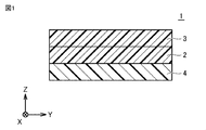
- the polarizing plate obtained by the method for manufacturing a polarizing plate may have optical films on both sides of the polarizing element. As shown in FIG. 1, in the polarizing plate 1, the polarizing element 2 is arranged between the first optical film 3 and the second optical film 4.
- the first optical film and the second optical film may be collectively referred to as an optical film or a pair of optical films.
- a first laminated body is produced by laminating a polarizer and an optical film and laminating them to each other.
- the polarizer and the optical film may be in the shape of a long strip.
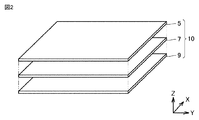
- the polarizer 7 is a pair of the first optical film 5 and the second optical film. Located between 9.
- the optical film can be attached to the polarizer via an adhesive layer made of an adhesive.
- the polarizer may be, for example, a polarizer in which iodine is adsorbed and oriented on a uniaxially stretched polyvinyl alcohol-based resin film, and polyvinyl alcohol molecular chains are crosslinked with boric acid.
- the polarizer is an absorption type polarizer having a property of absorbing linearly polarized light having a vibration plane parallel to the absorption axis and transmitting linearly polarized light having a vibration plane orthogonal to the absorption axis (parallel to the transmission axis). be able to.
- the polarizer can be produced, for example, by subjecting a polyvinyl alcohol-based resin film (hereinafter, also referred to as PVA film) to a stretching treatment, a dyeing treatment, and a cross-linking treatment.
- PVA film polyvinyl alcohol-based resin film
- the stretching treatment, the dyeing treatment and the cross-linking treatment can be carried out by known methods.
- the polyvinyl alcohol-based resin film may be in the shape of a long strip or in the shape of a single leaf.
- the PVA film is stretched in the uniaxial direction or the biaxial direction.
- the bicolor ratio of the uniaxially stretched polarizer tends to be high.
- the PVA film is dyed with iodine, a dichroic dye (polyiodine) or an organic dye using a stain.
- the staining solution may contain boric acid, zinc sulfate, or zinc chloride.
- the PVA film may be washed with water before dyeing. Washing with water removes stains and anti-blocking agents from the surface of the PVA film. Further, as a result of the PVA film swelling due to washing with water, dyeing spots (non-uniform dyeing) are likely to be suppressed.
- the dyed PVA film is treated with a solution of a cross-linking agent containing boric acid (eg, an aqueous solution of boric acid) for cross-linking. After treatment with a cross-linking agent, the PVA film is washed with water and then dried. Through the above procedure, a polarizer containing a resin film containing boric acid and iodine can be obtained.
- the polyvinyl alcohol (PVA) -based resin is obtained by saponifying a polyvinyl acetate-based resin.
- the polyvinyl acetate-based resin is, for example, polyvinyl acetate, which is a homopolymer of vinyl acetate, or a copolymer of vinyl acetate and another monomer (for example, an ethylene-vinyl acetate copolymer). Good. Other monomers copolymerizing with vinyl acetate may be unsaturated carboxylic acids, olefins, vinyl ethers, unsaturated sulfonic acids, or acrylamides having an ammonium group, in addition to ethylene.
- the polyvinyl alcohol-based resin may be modified with aldehydes.
- the modified polyvinyl alcohol-based resin may be, for example, partially formalized polyvinyl alcohol, polyvinyl acetal, or polyvinyl butyral.
- the polyvinyl alcohol-based resin may be a polyene-based oriented film such as a dehydrated product of polyvinyl alcohol or a dehydrochlorinated product of polyvinyl chloride. Staining may be performed before stretching, or stretching may be performed in a dyeing solution.
- the length of the stretched resin film may be, for example, 3 to 7 times the length before stretching.
- the thickness of the polarizer may be, for example, 15 ⁇ m or less, preferably 10 ⁇ m or less, and more preferably 8 ⁇ m or less.
- the thickness of the polarizer is usually 1 ⁇ m or more, and may be, for example, 3 ⁇ m or more. The thinner the polarizer, the easier it is to suppress the contraction or expansion of the polarizer itself due to a temperature change, and the easier it is to suppress the change in the dimensions of the polarizer itself. As a result, stress is less likely to act on the polarizer, and cracks in the polarizer tend to be suppressed more easily.
- the optical film may be a translucent thermoplastic resin.
- the optical film may be an optically transparent thermoplastic resin.
- the resin constituting the optical film is, for example, a chain polyolefin resin, a cyclic olefin polymer resin (COP resin), a cellulose ester resin, a polyester resin, a polycarbonate resin, a (meth) acrylic resin, or a polystyrene resin. , Or a mixture or copolymer of these.
- the composition of the first optical film may be exactly the same as the composition of the second optical film.
- both the first optical film and the second optical film may contain a cyclic olefin polymer-based resin (COP-based resin).
- COP-based resin cyclic olefin polymer-based resin
- the effects of the present invention can be easily obtained.
- the composition of the first optical film may be different from the composition of the second optical film.
- the glass transition temperature of the first optical film and the second optical film is preferably 100 ° C. or higher and 200 ° C. or lower, or 120 ° C. or higher and 150 ° C. or lower.
- the glass transition temperature of each of the first optical film and the second optical film is in the above range, the first optical film and the second optical film are fused to each other by the heat generated by polishing the edge of each optical film. easy.
- the chain polyolefin resin may be, for example, a homopolymer of a chain olefin such as a polyethylene resin or a polypropylene resin.
- the chain polyolefin resin may be a copolymer composed of two or more kinds of chain olefins.
- the cyclic olefin polymer resin may be, for example, a ring-opening (co) polymer of cyclic olefin or an addition polymer of cyclic olefin.
- the cyclic olefin polymer-based resin may be, for example, a copolymer of a cyclic olefin and a chain olefin (for example, a random copolymer).
- the chain olefin constituting the copolymer may be, for example, ethylene or propylene.
- the cyclic olefin polymer resin may be a graft polymer obtained by modifying the above polymer with an unsaturated carboxylic acid or a derivative thereof, or a hydride thereof.
- the cyclic olefin polymer-based resin may be, for example, a norbornene-based resin using a norbornene-based monomer such as norbornene or a polycyclic norbornene-based monomer.
- the cellulosic ester resin may be, for example, cellulose triacetate (triacetyl cellulose (TAC)), cellulose diacetate, cellulose tripropionate or cellulose dipropionate. These copolymers may be used. A cellulosic ester resin in which a part of the hydroxyl group is modified with another substituent may be used.
- TAC triacetyl cellulose
- a cellulosic ester resin in which a part of the hydroxyl group is modified with another substituent may be used.
- a polyester resin other than the cellulose ester resin may be used.
- the polyester resin may be, for example, a polycondensate of a polyvalent carboxylic acid or a derivative thereof and a polyhydric alcohol.
- the polyvalent carboxylic acid or a derivative thereof may be a dicarboxylic acid or a derivative thereof.
- the polyvalent carboxylic acid or a derivative thereof may be, for example, terephthalic acid, isophthalic acid, dimethyl terephthalate, or dimethyl naphthalenedicarboxylic acid.
- the polyhydric alcohol may be, for example, a diol.
- the polyhydric alcohol may be, for example, ethylene glycol, propanediol, butanediol, neopentyl glycol, or cyclohexanedimethanol.
- the polyester resin may be, for example, polyethylene terephthalate, polybutylene terephthalate, polyethylene naphthalate, polybutylene naphthalate, polytrimethylene terephthalate, polytrimethylene naphthalate, polycyclohexanedimethylterephthalate, or polycyclohexanedimethylnaphthalate. ..
- Polycarbonate-based resin is a polymer in which polymerization units (monomers) are bonded via carbonate groups.
- the polycarbonate-based resin may be a modified polycarbonate having a modified polymer skeleton, or may be a copolymerized polycarbonate.
- the (meth) acrylic resin is, for example, a poly (meth) acrylic acid ester (for example, polymethyl methacrylate (PMMA)); a methyl methacrylate- (meth) acrylic acid copolymer; a methyl methacrylate- (meth) acrylic.
- a poly (meth) acrylic acid ester for example, polymethyl methacrylate (PMMA)
- PMMA polymethyl methacrylate
- a methyl methacrylate- (meth) acrylic acid copolymer for example, a methyl methacrylate- (meth) acrylic.
- Acid ester copolymer Methyl methacrylate-acrylic acid ester- (meth) acrylic acid copolymer; (meth) methyl acrylate-styrene copolymer (for example, MS resin); methyl methacrylate and alicyclic hydrocarbon It may be a copolymer with a compound having a group (for example, methyl methacrylate-cyclohexyl methacrylate copolymer, methyl methacrylate- (meth) acrylate norbornyl copolymer, etc.).
- the first optical film or the second optical film is at least one selected from the group consisting of lubricants, plasticizers, dispersants, heat stabilizers, ultraviolet absorbers, infrared absorbers, antistatic agents, and antioxidants. Additives may be included.
- the thickness of the first optical film may be, for example, 5 ⁇ m or more and 90 ⁇ m or less, or 10 ⁇ m or more and 60 ⁇ m or less.
- the thickness of the second optical film may also be, for example, 5 ⁇ m or more and 90 ⁇ m or less, or 10 ⁇ m or more and 60 ⁇ m or less.
- At least one of the first optical film and the second optical film may be a film having an optical function.
- the film having an optical function may be, for example, a retardation film or a brightness improving film. For example, by stretching a film made of the above-mentioned thermoplastic resin or forming a liquid crystal layer or the like on the film, a retardation film to which an arbitrary retardation value is given can be obtained.
- the first optical film may be superposed on the polarizer via an adhesive layer.
- the second optical film may also be laminated on the side of the polarizer opposite to the first optical film via the adhesive layer.
- the adhesive layer may contain an aqueous adhesive such as polyvinyl alcohol.
- the adhesive layer may contain an active energy ray-curable resin described later.
- the active energy ray-curable resin is a resin that cures when irradiated with active energy rays.
- the active energy ray may be, for example, ultraviolet light, visible light, electron beam, or X-ray.
- the active energy ray-curable resin may be an ultraviolet curable resin.
- the active energy ray-curable resin may be a kind of resin and may contain a plurality of kinds of resins.
- the active energy ray-curable resin may contain a cationically polymerizable curable compound or a radically polymerizable curable compound.
- the active energy ray-curable resin may contain a cationic polymerization initiator or a radical polymerization initiator for initiating the curing reaction of the curable compound.
- the cationically polymerizable curable compound may be, for example, an epoxy compound (a compound having at least one epoxy group in the molecule) or an oxetane compound (a compound having at least one oxetane ring in the molecule).
- the radically polymerizable curable compound may be, for example, a (meth) acrylic compound (a compound having at least one (meth) acryloyloxy group in the molecule).
- the radically polymerizable curable compound may be a vinyl compound having a radically polymerizable double bond.
- the active energy ray-curable resin can be used as a cationic polymerization accelerator, an ion trapping agent, an antioxidant, a chain transfer agent, a tackifier, a thermoplastic resin, a filler, a flow conditioner, a plasticizer, and a defoaming agent, if necessary. It may contain agents, antistatic agents, leveling agents, solvents and the like.
- Humidification treatment is performed by holding the first laminate in a gas phase having a relative humidity of 75% RH or more at a temperature of 35 ° C. or higher.
- a region containing boric acid at a concentration lower than the concentration of boric acid in a region other than this region (hereinafter, also referred to as a boric acid low content region)
- iodine does not escape, and the linear polarization ability is exhibited even in the boric acid low content region.
- the polarizing plate manufactured by the manufacturing method of the present invention does not crack even in the heat shock test, and can exhibit linear polarization ability even in the region including the end portion.
- Patent Document 1 it is known that it is effective to reduce the concentration of boric acid contained at the end of the polarizer in order to suppress the occurrence of cracks in the heat shock test.
- boric acid is removed from the end of the polarizer and the entire region from the end to 50 ⁇ m or more, and as a result, 300 ⁇ m from the end and the end of the polarizer. It was found that iodine escape occurred over the entire region of the width exceeding the width, and the linear polarization ability could not be exhibited at the end.
- the production method of the present invention it is the excess iodine contained in the end of the polarizer that is removed by performing the humidification treatment that keeps it in the gas phase at a temperature of 35 ° C. or higher and a relative humidity of 75% RH or higher. Since it is only an acid and iodine tends to be less likely to escape, the obtained polarizing plate can suppress the occurrence of cracks in the heat shock test and can exhibit linear polarization ability even at the end portion.
- the concentration of boric acid is the concentration of boric acid per unit area including the thickness direction of the polarizing plate.
- boric acid includes, for example, a boric acid molecule (H 3 BO 3 ) and a borate ion (BO 3 3- ).
- the region where iodine is missing (hereinafter, also referred to as iodine loss region for short) is a region visually observed as a region through which light is transmitted in a cross-nicol state using a polarizing microscope.
- the iodine for example, molecular iodine (I 2), polyiodine complex (I 3 -, I 5 - ) - contains iodine ions (I).
- the plan view means that the polarizing plate is viewed from the thickness direction.
- the temperature of the gas phase is 35 ° C or higher. When the temperature of the gas phase is 35 ° C. or higher, excess boric acid contained in the end portion of the polarizing plate tends to be easily removed.
- the temperature of the gas phase is preferably 40 ° C. or higher from the viewpoint of facilitating the removal of boric acid.
- the temperature of the gas phase may be, for example, 90 ° C. or lower, preferably 85 ° C. or lower. When the temperature of the gas phase is 90 ° C. or lower, iodine loss tends to be less likely to occur.
- the temperature of the gas phase can be adjusted within the above range so that excess boric acid is removed at the ends of the polarizer and iodine does not escape.
- the relative humidity of the gas phase is 75% RH or more. When the relative humidity is 75% RH or more, excess boric acid contained in the end portion of the polarizing plate tends to be easily removed.
- the relative humidity of the gas phase is preferably 80% RH or more from the viewpoint of facilitating the removal of boric acid.
- the relative humidity of the gas phase may be, for example, 90% RH or less, preferably 85% RH or less. When the relative humidity of the gas phase is 90% RH or less, iodine loss tends to be less likely to occur.
- the relative humidity of the gas phase can be adjusted within the above range so that excess boric acid is removed at the ends of the polarizer and iodine does not escape.
- the time for performing the humidification treatment may be, for example, 0.5 hours or more and 4 hours or less, preferably 1 hour or more and 3 hours or less, and more preferably 1 from the viewpoint of easy removal of boric acid and prevention of iodine loss. .5 hours or more and 2.5 hours or less.
- the humidification treatment is usually carried out continuously for the above time.
- Humidification treatment can be performed using, for example, a constant temperature and constant humidity furnace.
- the humidification treatment is preferably performed so that the end region included in the deformed portion is humidified from the viewpoint of suppressing cracks and making iodine loss less noticeable. ..
- the concentration of boric acid in the region containing low boric acid is preferably higher as the concentration of boric acid increases inward from the end of the polarizing plate. It can be done so as to obtain a certain concentration. Such a concentration tends to be easily obtained when the temperature of the gas phase is lowered, the relative humidity is lowered, or the time for performing the humidifying treatment is shortened under the conditions of the humidifying treatment.
- the boric acid low content region may be formed, for example, in a region exceeding 15 ⁇ m in the inward direction from the end in the plan view of the polarizing plate, and is preferably formed in a region of more than 15 ⁇ m and less than 200 ⁇ m from the viewpoint of crack suppression, and more preferably. It is formed in a region of 20 ⁇ m or more and 150 ⁇ m or less, more preferably 20 ⁇ m or more and less than 100 ⁇ m, and particularly preferably 20 ⁇ m or more and less than 50 ⁇ m.
- the boric acid low content region may be formed even in a region of 15 ⁇ m or less from the end portion in the plan view of the polarizing plate.
- the boric acid low content region is continuously formed in the entire region of 15 ⁇ m or less from the end portion in the plan view of the polarizing plate and the entire region of more than 15 ⁇ m and less than 200 ⁇ m in the inward direction from the end portion in the plan view of the polarizing plate. You can.
- the boric acid low content region may be formed over the end of the polarizing plate in plan view and the entire region between the ends and less than 200 ⁇ m.
- the boundary between the boric acid low content region and the other region is the end and the end. It can be present in the region between the part and less than 200 ⁇ m.
- the boric acid low content region is preferably formed over the entire region between the ends and the ends in the plan view of the polarizing plate within 100 ⁇ m, and more preferably 50 ⁇ m or less from the ends and the ends in the plan view of the polarizing plate. It is formed over the entire region between, and more preferably at the ends in the plan view of the polarizing plate and over the entire region within 20 ⁇ m from the ends.
- the end of the polarizing plate does not have to contain boric acid.
- the boundary between the region where the low boric acid content region is formed and the region other than that is defined from the end obtained by, for example, the time-of-flight secondary ion mass spectrometry (TOF-SIMS) described in the column of Examples described later. It can be obtained from the boric acid concentration profile with respect to the distance of. For example, when a region where the borate ionic strength is constant can be read in the boric acid concentration profile, the average value of the borate ionic strength in that region is obtained, and the position where the borate ionic strength becomes the above average value from the end. Can be a boric acid low concentration site.
- the average borate ionic strength in the range of 30 ⁇ m inward from the point where the borate ionic strength is maximized in the borate concentration profile can be obtained, and the boric acid low concentration site can be set from the end to the position where the borate ionic strength becomes the above average value.
- the boric acid low content region may be one continuous region or a plurality of divided regions in the plan view of the polarizing plate.
- the boric acid low content region is preferably formed along the outer edge of the polarizing plate from the viewpoint of suppressing cracks.
- the boric acid low content region may be formed along the entire outer edge portion of the polarizing plate, or may be formed along a part of the outer edge portion of the polarizing plate.
- a polarizer having a region containing boric acid at a concentration lower than the concentration of boric acid in a region other than this region can be obtained at the end portion of the polarizer in a plan view.
- this polarizer is a polarizer in which a boric acid low concentration portion having a boric acid concentration lower than that of boric acid in the inner region 500 ⁇ m or more inside from the end is formed. In the inner region, the concentration of boric acid can be nearly uniform.
- the polarizer 2 shown in FIG. 3 may have a boric acid low concentration portion 30 in a region including an end portion in a plan view, and may have an inner region 32 inside 500 ⁇ m or more from the end portion.
- the inner region 32 can include an region for displaying an image when incorporated in a liquid crystal display device.
- the boric acid concentration in the intermediate region 31 between the boric acid low concentration portion 30 and the inner region 32 is usually substantially the same as the boric acid concentration in the inner region 32.
- this polarizer is a polarizer in which an iodine low concentration portion having an iodine concentration lower than the iodine concentration in the inner region is not formed.
- the method for producing a polarizing plate can further include a molding step of molding the first laminate before the humidification treatment step.
- the first laminated body can be molded into a predetermined shape by cutting and / or punching.
- the cutting and / or punching process can be performed by using a cutting tool or irradiating with a laser beam.
- the laser light may be a CO 2 laser.
- the size of the first laminated body may be adjusted to a size that is easy to process by the molding process.
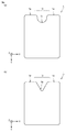
- a deformed portion may be formed on the outer edge portion of the first laminated body by punching or cutting.
- the deformed portion may be, for example, a concave portion formed on the outer edge portion, a substantially V-shaped portion convex in the inward direction, and a through hole formed in the plane in a plan view of the first laminated body.
- the first laminate may have two or more variant portions in the outer edge and / or in-plane.
- the through hole formed in the plane may be the above-mentioned camera hole or the like.
- a polarizing plate having a deformed portion tends to concentrate stress on the deformed portion and easily cracks.
- the polarizing plate of the present invention has a deformed portion, the occurrence of cracks tends to be easily suppressed in the heat shock test because the boric acid low content region is formed in the end region of the deformed portion.
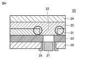
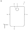
- the polarizing plate manufactured by the manufacturing method of the present invention is suitable for, for example, an image display device having a camera hole.
- the image display device 20 having the camera hole 22 the cover glass 24, the adhesive layer 25, the polarizing plate 21, the liquid crystal panel 23, the polarizing plate 26, the camera 27, and the light-shielding tape 28 as shown in FIG.
- the part forming the circled camera hole is easily visible directly. If iodine loss occurs in such a portion, iodine loss becomes conspicuous, and as a result, the design may be deteriorated.
- the polarizing plate of the present invention does not cause iodine loss in the region including the end portion, iodine loss is less noticeable and the design is less likely to deteriorate even when the polarizing plate is arranged on the visual side in the image display device.
- the deformed portion is a concave portion
- it is preferably formed so that the depth direction of the concave portion and the absorption axis (stretching axis direction) are orthogonal to each other from the viewpoint of crack suppression.
- the concave portion may be formed so that its depth direction intersects the absorption axis (stretching axis direction) at an angle of usually 30 ° or more and 60 ° or less.
- the method for manufacturing a polarizing plate further includes a cutting step of bringing the end mill into contact with the outer periphery of the first laminated body or the second laminated body described later and moving the end mill along the outer periphery of the laminated body before the humidification treatment step. Can be done. As shown in FIG. 2, the positions of the edges of the polarizer 7, the first optical film 5, and the second optical film 9 may be aligned over the entire outer circumference of the first laminated body 10 before the cutting process.
- the end mill 50 used in the cutting process has a blade (edge) 50e protruding on a side surface substantially parallel to the rotation axis 50a.
- the side surface of the end mill 50 is brought into contact with the outer circumference (end face) of the first laminated body 10, and the rotating end mill 50 is moved along the outer circumference of the first laminated body 10.
- the rotating end mill 50 may be moved along the path indicated by the arrow in FIG.
- the outer circumference (end face) of the first laminated body 10 is cut or polished by the blade 50e, the outer circumference (end face) of the first laminated body 10 becomes smooth, the concave portion 13 is formed, and the inside of the concave portion 13 is formed.
- the corners are chamfered.
- a plurality of first laminated bodies 10 are stacked to form a second laminated body 100, and then the side surface of the end mill 50 is brought into contact with the outer periphery (end face) of the second laminated body 100 to rotate.
- the end mill 50 may be moved along the outer circumference of the second laminated body 100. That is, in the cutting step, the outer circumferences of the plurality of first laminated bodies 10 constituting the second laminated body 100 may be collectively cut or polished by the end mill 50.
- the corners located at both ends of the concave portion 13 and the corners located at the four corners of the first laminated body 10 may be chamfered.
- the cutting amount of the end mill in the cutting step may be, for example, 10 ⁇ m or more and 500 ⁇ m or less, preferably 50 rpm or more and 150 ⁇ m or less.
- the cutting process may be repeated three or more times.
- chips generated in the second cutting step may be removed from the end face of the first laminated body 10 with almost no cutting of the first laminated body 10.
- a plurality of end mills may be used in each cutting process.
- the feed rate of the end mill in the cutting process may be 100 mm / min or more and less than 3000 mm / min.
- the rotation speed of the end mill in the cutting step may be, for example, 500 rpm or more and 60,000 rpm or less, preferably 10,000 rpm or more and 60,000 rpm or less.
- the cutting angle in the cutting step may be, for example, 30 ° or more and 70 ° or less, preferably 45 ° or more and 65 ° or less.
- the cutting angle ⁇ is defined as 90 ° ⁇ . As shown in FIG.
- the twist angle ⁇ of the end mill 50 is an angle formed by the direction d1 in which the blade 50e extends on the side surface of the end mill 50 and the rotation axis 50a of the end mill 50.
- the cutting angle ⁇ may be rephrased as the angle formed by the direction d1 in which the blade 50e extends and the direction d2 perpendicular to the rotation axis 50a.
- the diameter ⁇ (thickness) of the end mill 50 used in the cutting step may be, for example, 3.0 mm or more and 6.0 mm or less.
- the position of the end portion of the optical film and the position of the end portion of the polarizer are the same in the plan view of the first laminated body or the second laminated body.
- the first laminated body or the second laminated body can be machined so as to be. Therefore, the obtained polarizing plate can have a linear polarization ability up to the end portion of the polarizing plate at the end portion formed by cutting.
- the polarizer according to another embodiment of the present invention is a polarizer containing a resin film containing boric acid and iodine and having a thickness of 15 ⁇ m or less.
- the polarizer may be, for example, a polarizer in which iodine is adsorbed and oriented on a uniaxially stretched polyvinyl alcohol-based resin film, and polyvinyl alcohol molecular chains are crosslinked with boric acid.
- the polarizer is an absorption type polarizer having a property of absorbing linearly polarized light having a vibration plane parallel to the absorption axis and transmitting linearly polarized light having a vibration plane orthogonal to the absorption axis (parallel to the transmission axis). be able to.
- the polarizer has a region containing boric acid at a concentration lower than the concentration of boric acid in a region other than the region including the end of the polarizer (hereinafter, also referred to as a boric acid low content region of the polarizer).
- a boric acid low content region of the polarizer it is a polarizer in which iodine does not escape in the region including the end of the polarizer. Therefore, the polarizer of the present invention can suppress the occurrence of cracks in the heat shock test and can exhibit linear polarization ability even at the end portion.
- the concentration of boric acid in the boric acid low content region of the polarizer is preferably from the end in the inner direction from the end of the polarizing plate. The farther away it is, the higher it becomes.
- the boric acid low content region of the polarizer may be formed in a region exceeding 15 ⁇ m in the inward direction from the end in a plan view of the polarizer, and is preferably formed in a region of more than 15 ⁇ m and less than 200 ⁇ m from the viewpoint of crack suppression. It may be formed in a region of 20 ⁇ m or more and 150 ⁇ m or less, more preferably 20 ⁇ m or more and less than 100 ⁇ m, and particularly preferably 20 ⁇ m or more and less than 50 ⁇ m. Good.
- the boric acid low content region of the polarizer may be formed even in a region of 15 ⁇ m or less from the end portion in the plan view of the polarizer.
- the boric acid low content region of the polarizer is continuously divided into the entire region of 15 ⁇ m or less from the end in the plan view of the polarizer and the entire region of more than 15 ⁇ m and less than 200 ⁇ m in the medial direction from the end in the plan view of the polarizer. It may be formed.
- the boric acid low content region of the polarizer may be formed over the end of the polarizer and the entire region between the ends in less than 200 ⁇ m in plan view.
- the boric acid low content region of the polarizer When the boric acid low content region of the polarizer is formed over the entire region between the end portion and the end portion in the plan view of the polarizer and less than 200 ⁇ m, the boric acid low content region of the polarizer and the other region Boundaries can be present at the edges and in the region between the edges and less than 200 ⁇ m.
- the boric acid low content region of the polarizer is preferably formed over the end and the entire region within 100 ⁇ m or less from the end in the plan view of the polarizer, and more preferably from the end and the end in the plan view of the polarizer. It is formed over the entire region between 50 ⁇ m and below, more preferably at the ends in plan view of the polarizer and over the entire region between 20 ⁇ m and below.
- the ends of the polarizer do not have to contain boric acid.
- the boundary between the region where the boric acid low content site is formed and the other region can be determined by the method described in the above-mentioned method for producing a polarizing plate.
- the boric acid low content region of the polarizer may be one continuous region or a plurality of divided regions in the plan view of the polarizer.
- the boric acid low content region of the polarizer is preferably formed along the outer edge of the polarizer from the viewpoint of suppressing cracks.
- the boric acid low content region may be formed along the entire outer edge of the polarizer, or may be formed along a part of the outer edge of the polarizer.
- the boric acid low content region of the polarizer can be a boric acid concentration lower than the boric acid concentration in the inner region 500 ⁇ m or more inside from the end portion.
- the concentration of boric acid can be nearly uniform.
- the polarizer can have a boric acid low concentration portion 30 in a region including an end portion in a plan view, and an inner region 32 inside 500 ⁇ m or more from the end portion.
- the inner region 32 can include an region for displaying an image when incorporated in a liquid crystal display device.
- the boric acid concentration in the intermediate region 31 between the boric acid low concentration portion 30 and the inner region 32 is usually substantially the same as the boric acid concentration in the inner region 32.
- the polarizer in which iodine loss does not occur is specifically a polarizer in which an iodine low concentration portion having an iodine concentration lower than the iodine concentration in the inner region is not formed.
- the presence or absence of iodine low concentration sites can be confirmed by the method of measurement in the column of Examples described later.
- the example and preferable range of the thickness of the polarizer As the example and preferable range of the thickness of the polarizer, the example and the preferable range in the above description of the method for manufacturing a polarizing plate are applied.
- the polarizer may form a deformed portion on the outer edge portion.
- the deformed portion may be, for example, a concave portion formed on the outer edge portion, a substantially V-shaped portion convex in the inward direction, and a through hole formed in the plane in a plan view of the polarizer.
- the polarizer may have two or more variants in the outer edge and / or in-plane.
- the through hole formed in the plane may be the above-mentioned camera hole or the like. Since the polarizer does not cause iodine loss in the region including the end portion, even when it is used for a polarizing plate arranged on the visual side in an image display device, iodine loss is less noticeable and the design is less likely to deteriorate.
- the polarizer can be produced, for example, by subjecting a uniaxially stretched polyvinyl alcohol-based resin film containing boric acid and iodine to a humidifying treatment.
- a humidifying treatment As an example and a preferable range of the humidifying treatment conditions, the example and the preferable range of the humidifying treatment conditions described in the above-mentioned method for producing a polarizing plate can be applied.
- the polarizing plate according to still another embodiment of the present invention includes the above-mentioned polarizing element and an optical film bonded to at least one side of the polarizing element.
- the examples and preferred ranges of the optical film the examples and preferred ranges described in the above-mentioned method for producing a polarizing plate are applied.
- the polarizing plate 1 is a film-shaped polarizing element 2 located between at least a pair of optical films (3, 4) and a pair of optical films (3, 4). To be equipped with.
- the polarizing plate 1 composed of the polarizing element 2 and the pair of optical films (3, 4) will be mainly described.
- the number of optical films included in the polarizing plate is not limited to two.
- the optical film means a film-like member (excluding the polarizer 2 itself) that constitutes the polarizing plate 1.
- optical film implies a protective film and a release film.
- Each optical film does not have to have a specific optical function by itself.
- the "film” (optical film) may be paraphrased as the "layer” (optical layer).
- Each pair of optical films (3, 4) contains a resin.
- the composition of each of the optical films (3, 4) is not limited.
- Each pair of optical films (3, 4) contains a resin.
- the composition of each of the optical films (3, 4) is not limited.
- the polarizer 2 directly or indirectly overlaps with the optical films (3, 4), respectively.
- the polarizer 2 may overlap the optical films (3, 4) with the adhesive layer.
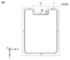
- FIG. 7 shows the surface (light receiving surface) of the polarizing plate 1 according to the present embodiment.
- the cross section of the polarizing plate 1 shown in FIG. 7 is perpendicular to the surface (light receiving surface) of the polarizing plate 1 and orthogonal to the outer circumference 1p of the polarizing plate 1 located inside the recess 13.
- the recess 13 is formed on the outer peripheral 1p of the polarizing plate 1. That is, there is a recess 13 on the outer circumference 1p of the polarizing plate 1.
- the recess 13 may be paraphrased as a recess, a cut or a notch.
- the recess 13 may penetrate the polarizing plate 1 in a direction (Z-axis direction) perpendicular to the surface (light receiving surface) of the polarizing plate 1.
- the outer circumference 1p of the polarizing plate 1 may be rephrased as the outer edge or contour of the polarizing plate 1 (light receiving surface) seen from the direction perpendicular to the light receiving surface of the polarizing plate 1.
- the inner corner 13c of the recess 13 may be a curved surface. That is, the end face of the polarizing plate 1 located at the inner corner 13c of the recess 13 may be a curved surface. That is, the inner corner 13c of the recess may be chamfered. Since the inner corner 13c of the recess 13 is a curved surface, cracks in the inner corner 13c of the recess 13 are likely to be suppressed. As shown in FIG. 7, the corners located at both ends of the recess 13 and the corners located at the four corners of the polarizing plate 1 may also be chamfered.
- the width of the recess 13 (the width of the recess 13 in the X-axis direction) is not particularly limited, but may be, for example, 3 mm or more and 160 mm or less.
- the depth of the recess 13 (width of the recess 13 in the Y-axis direction) is not particularly limited, but may be, for example, 0.5 mm or more and 160 mm or less.
- the length of the side (short side) of the polarizing plate 1 on which the recess 13 is formed is not particularly limited, but may be, for example, 30 mm or more and 90 mm or less.
- the length of the side (long side) of the polarizing plate 1 in which the recess 13 is not formed is not particularly limited, but may be, for example, 30 mm or more and 170 mm or less.
- the thickness of the entire polarizing plate 1 is not particularly limited, but may be, for example, 30 ⁇ m or more and 300 ⁇ m or less.
- the recess 13 shown in FIG. 7 has a rectangular shape (rectangular shape).
- the shape of the recess 13 is not limited.
- the recess 13 may be square.
- the recess 13 may be a polygon other than a quadrangle and a triangle.
- the shape of the recess 13 may be a semicircle.
- the shape of the recess 13 may be triangular.
- the entire recess 13 may be curved.
- the recess 13 may be composed of a straight line and a curved line.
- a plurality of recesses 13 may be formed on the outer circumference 1p of the polarizing plate 1.
- a plurality of recesses 13 may be formed on one side constituting the outer peripheral 1p of the polarizing plate 1.
- the recess 13 may be formed by cutting out at least one of the four corners of the rectangular polarizing plate 1.
- the overall shape of the polarizing plate 1 excluding the recess 13 is substantially quadrangular (rectangular).
- the shape of the polarizing plate 1 is not limited.
- the shape of the polarizing plate 1 may be square.
- the shape of the polarizing plate 1 may be a polygon other than a quadrangle, a circle, or an ellipse.
- the overall shapes of the polarizer 2 and the optical films (3, 4) may be substantially the same as the shape of the polarizing plate 1.
- the recess 13 is formed on the short side of the polarizing plate 1, but the recess 13 may be formed on the long side of the polarizing plate 1.
- the polarizer 1 may have a through hole in the plane in a plan view.
- the diameter of the through hole may be, for example, 0.5 mm or more and 30 mm or less, preferably 1 mm or more and 10 mm or less.
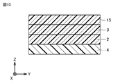
- the polarizing plate may further include another optical film containing a resin in addition to the pair of optical films composed of the first optical film and the second optical film. That is, the polarizing plate may include three or more optical films.
- the polarizing plate has a polarizing element 2 located between the first optical film 3 and the second optical film 4, the first optical film 3 and the second optical film 4, and a first.
- a third optical film 15 that overlaps the optical film 3 may be provided.
- the third optical film 15 may be superposed on the first optical film 3 via the adhesive layer described above.
- the resin contained in the third optical film 15 may be at least one of the above-mentioned resins listed as the resin contained in each of the first optical film 3 and the second optical film 4.
- the composition of the third optical film 15 may be the same as the composition of the first optical film 3.
- the composition of the third optical film 15 may be different from the composition of the first optical film 3.
- the composition of the third optical film 15 may be the same as the composition of the second optical film 4.
- the composition of the third optical film 15 may be different from the composition of the second optical film 4.
- the thickness of the third optical film 15 may be, for example, 5 ⁇ m or more and 200 ⁇ m or less.
- the third optical film 15 may be peeled off and removed from the polarizing plate in the manufacturing process of the image display device. That is, the third optical film 15 may be a temporary optical film.
- the polarizing plate may further include an adhesive layer that overlaps one of the pair of optical films and a release film that overlaps the adhesive layer.
- the polarizing plate shown in FIG. 10 may further include an adhesive layer that overlaps the second optical film 4 and a release film that overlaps the adhesive layer.
- the adhesive layer may contain, for example, a pressure-sensitive adhesive such as an acrylic pressure-sensitive adhesive, a rubber-based pressure-sensitive adhesive, a silicone-based pressure-sensitive adhesive, or a urethane-based pressure-sensitive adhesive.
- the thickness of the adhesive layer may be, for example, 2 ⁇ m or more and 100 ⁇ m or less.
- the resin contained in the release film may be at least one of the above-mentioned resins listed as the resin contained in each of the first optical film 3 and the second optical film 4.
- the composition of the release film may be the same as the composition of the first optical film 3.
- the composition of the release film may be different from the composition of the first optical film 3.
- the composition of the release film may be the same as the composition of the second optical film 4.
- the composition of the release film may be different from the composition of the second optical film 4.
- the thickness of the release film may be, for example, 10 ⁇ m or more and 100 ⁇ m or less.
- the release film may be peeled off and removed from the polarizing plate in the manufacturing process of the image display device.
- the release film may be arranged on both sides of the polarizing plate via the adhesive layer.
- the polarizing plate may be a reflective polarizing film, a film with an antiglare function, a film with a surface antireflection function, a reflection film, a transflective reflective film, a viewing angle compensation film, a window film, an antistatic layer, or a hard coat. It may further include at least one selected from the group consisting of a layer, an optical compensation layer, a touch sensor layer, and an antifouling layer.
- the polarizing plate can be used in an image display device.
- the image display device include a liquid crystal display device, an organic EL display device, and the like.
- the polarizing plate may be used for a polarizing plate arranged on the viewing side of the image display device, may be used for a polarizing plate arranged on the backlight side of the image display device, and may be used for the viewing side and the backlight. It may be used for both polarizing plates on the side. Since the color loss portion of the polarizing plate is inconspicuous, the design is not easily impaired even when it is used on the visual side of the image display device. Therefore, the image display device is suitable as an image display device having a camera hole, for example, a mobile device such as a smartphone or a mobile phone, a personal computer, or the like.
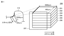
- the measurement sample 200 includes an optical film 201 (thickness 52 ⁇ m), an adhesive layer 202 (thickness 1 ⁇ m), a polarizer 203 (thickness 8 ⁇ m), an adhesive layer 204 (thickness 1 ⁇ m), an optical film 205 (thickness 21 ⁇ m), and an adhesive layer 206 (thickness 21 ⁇ m).
- the thickness was 20 ⁇ m) in this order.
- the ion beam is irradiated while scanning the measurement region 207 on the side surface of the measurement sample 200 in the length direction (1000 ⁇ m) to obtain a two-dimensional distribution of the signal intensity of borate ions on this side surface, and from the obtained two-dimensional distribution.
- a portion corresponding to the side surface of the polarizer was cut out, and the integrated value of the signal intensity was plotted against the length direction of the measurement sample 200 to obtain a profile of the boric acid concentration with respect to the length direction.
- the conditions for time-of-flight secondary ion mass spectrometry (TOF-SIMS) are shown below.
- TOF-SIMS time-of-flight secondary ion mass spectrometry
- a polarizer having a thickness of 28 ⁇ m was obtained in the same manner as a polarizer having a thickness of 8 ⁇ m, except that a polarizer having a thickness of 28 ⁇ m was obtained by uniaxial stretching about 4 times by dry stretching.
- COP Cycloolefin resin film with a thickness of 23 ⁇ m (manufactured by Nippon Zeon Corporation).
- TAC A 20 ⁇ m-thick triacetyl cellulose film (manufactured by Konica Minolta Co., Ltd.).
- Example 1 An optical film (COP film) subjected to a corona discharge treatment was bonded to both sides of the 8 ⁇ m polarizer via an aqueous adhesive. An adhesive was applied to the surface of one optical film opposite to the polarizer to form an adhesive layer, and a separate film was bonded onto the adhesive layer. This separate film was removable from the pressure-sensitive adhesive layer. A protective film was attached to the side opposite to the polarizer of the optical film different from the optical film provided with the adhesive layer. This protective film could be peeled off from the optical film. The polarizing plate thus obtained was chip-cut into a 5.5 cm square, and a punching blade was used to perform deformed processing to provide a through hole having a diameter of 6 mm.
- the obtained polarizing plate was subjected to a humidification treatment in which the obtained polarizing plate was continuously held in a gas phase at a temperature of 85 ° C. and a relative humidity of 85% for 2 hours. In this way, the polarizing plate of Example 1 was obtained.
- the results are shown in Table 1.
- this polarizing plate did not cause light leakage due to iodine loss, and the length from the end of the iodine low concentration portion was 0 ⁇ m.
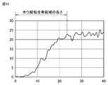
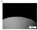
- Example 2 The polarizing plate of Example 2 was produced in the same manner as in Example 1 except that the conditions of the humidification treatment were changed to the conditions shown in Table 1. The results are shown in Table 1. Further, FIG. 12 shows the measurement result of the boric acid concentration with respect to the distance from the end of the polarizing plate. Further, FIG. 13 shows the observation result of iodine loss.
- Example 3 The polarizing plate of Example 3 was produced in the same manner as in Example 1 except that the conditions of the humidification treatment were changed to the conditions shown in Table 1. The results are shown in Table 1.
- Comparative Example 1 The polarizing plate of Comparative Example 1 was produced in the same manner as in Example 1 except that the conditions of the humidification treatment were changed to the conditions shown in Table 1. The results are shown in Table 1.
- Comparative Example 2 The polarizing plate of Comparative Example 2 was produced in the same manner as in Example 1 except that the conditions of the humidification treatment were changed to the conditions shown in Table 1. The results are shown in Table 1.
- Comparative Example 3 The polarizing plate of Comparative Example 3 was prepared in the same manner as in Example 1 except that it was immersed in warm water at a temperature of 74 ° C. for 16 minutes instead of being humidified. The results are shown in Table 1. The iodine loss observation result is shown in FIG. This polarizing plate had a low iodine concentration site due to iodine loss, and its length was about 250 ⁇ m.
- Example 4 An optical film COP that has undergone corona discharge treatment via a water-based adhesive is attached to one surface of a 12 ⁇ m polarizer, and an optical film that has undergone corona discharge treatment via a water-based adhesive on the other surface. TAC was bonded to prepare a polarizing plate. The obtained polarizing plate was chip-cut into a 5.5 cm square, and a deformed shape was performed to provide a through hole having a diameter of 6 mm.
- the obtained polarizing plate was subjected to a humidification treatment in which it was held in a gas phase at a temperature of 85 ° C. and a relative humidity of 85% for 2 hours. In this way, the polarizing plate of Example 4 was obtained.
- the results are shown in Table 2.
- Example 5 The polarizing plate of Example 5 was prepared in the same manner as in Example 4 except that the conditions of the humidification treatment were changed to the conditions shown in Table 2. The results are shown in Table 2.
- Comparative Example 4 The polarizing plate of Comparative Example 4 was produced in the same manner as in Example 4 except that the conditions of the humidification treatment were changed to the conditions shown in Table 2. The results are shown in Table 2.
- Comparative Example 5 The polarizing plate of Comparative Example 5 was produced in the same manner as in Example 4 except that the conditions of the humidification treatment were changed to the conditions shown in Table 2. The results are shown in Table 2.
- Comparative Example 6 The polarizing plate of Comparative Example 6 was produced in the same manner as in Example 4 except that the conditions of the humidification treatment were changed to the conditions shown in Table 2. The results are shown in Table 2.
- the obtained polarizing plate was subjected to a humidification treatment in which it was held in a gas phase at a temperature of 85 ° C. and a relative humidity of 85% for 2 hours. In this way, the polarizing plate of Comparative Example 7 was obtained.
- the results are shown in Table 3 together with the results of Example 1 and Example 2.
- Comparative Example 8 The polarizing plate of Comparative Example 8 was produced in the same manner as in Comparative Example 7 except that the conditions of the humidification treatment were changed to the conditions shown in Table 3. The results are shown in Table 3 together with the results of Example 1 and Example 2.
Landscapes
- Physics & Mathematics (AREA)
- General Physics & Mathematics (AREA)
- Optics & Photonics (AREA)
- Nonlinear Science (AREA)
- Mathematical Physics (AREA)
- Chemical & Material Sciences (AREA)
- Crystallography & Structural Chemistry (AREA)
- Polarising Elements (AREA)
- Devices For Indicating Variable Information By Combining Individual Elements (AREA)
- Liquid Crystal (AREA)
Priority Applications (3)
| Application Number | Priority Date | Filing Date | Title |
|---|---|---|---|
| CN202411633606.9A CN119270412A (zh) | 2019-09-12 | 2020-08-06 | 偏振板和图像显示装置 |
| CN202080063665.0A CN114391115B (zh) | 2019-09-12 | 2020-08-06 | 偏振板的制造方法 |
| KR1020227011170A KR20220057594A (ko) | 2019-09-12 | 2020-08-06 | 편광판의 제조 방법 |
Applications Claiming Priority (2)
| Application Number | Priority Date | Filing Date | Title |
|---|---|---|---|
| JP2019166289A JP7397605B2 (ja) | 2019-09-12 | 2019-09-12 | 偏光板の製造方法 |
| JP2019-166289 | 2019-09-12 |
Publications (1)
| Publication Number | Publication Date |
|---|---|
| WO2021049216A1 true WO2021049216A1 (ja) | 2021-03-18 |
Family
ID=74863973
Family Applications (1)
| Application Number | Title | Priority Date | Filing Date |
|---|---|---|---|
| PCT/JP2020/030138 Ceased WO2021049216A1 (ja) | 2019-09-12 | 2020-08-06 | 偏光板の製造方法 |
Country Status (5)
| Country | Link |
|---|---|
| JP (2) | JP7397605B2 (enExample) |
| KR (1) | KR20220057594A (enExample) |
| CN (2) | CN114391115B (enExample) |
| TW (1) | TWI878336B (enExample) |
| WO (1) | WO2021049216A1 (enExample) |
Families Citing this family (4)
| Publication number | Priority date | Publication date | Assignee | Title |
|---|---|---|---|---|
| JP2022075144A (ja) * | 2020-11-06 | 2022-05-18 | 日東電工株式会社 | 曲面加工された偏光板およびその製造方法 |
| JP2022075143A (ja) * | 2020-11-06 | 2022-05-18 | 日東電工株式会社 | 曲面加工された偏光板およびその製造方法 |
| JP2022147184A (ja) * | 2021-03-23 | 2022-10-06 | 日東電工株式会社 | 偏光板およびその製造方法 |
| CN116819819A (zh) * | 2023-07-26 | 2023-09-29 | 业成科技(成都)有限公司 | 液晶显示器改良结构 |
Citations (14)
| Publication number | Priority date | Publication date | Assignee | Title |
|---|---|---|---|---|
| JPH05119216A (ja) * | 1991-10-28 | 1993-05-18 | Mitsubishi Gas Chem Co Inc | 偏光板の製造法 |
| JPH07325219A (ja) * | 1994-04-08 | 1995-12-12 | Sumitomo Chem Co Ltd | 偏光板の製造方法 |
| JP2004279931A (ja) * | 2003-03-18 | 2004-10-07 | Fuji Photo Film Co Ltd | 偏光板およびその製造方法 |
| JP2005107238A (ja) * | 2003-09-30 | 2005-04-21 | Sony Chem Corp | 偏光板 |
| JP2006023573A (ja) * | 2004-07-08 | 2006-01-26 | Nitto Denko Corp | 偏光板の製造方法、偏光板およびそれを用いた画像表示装置 |
| JP2008009237A (ja) * | 2006-06-30 | 2008-01-17 | Sumitomo Chemical Co Ltd | 複合偏光板、液晶表示装置、及び複合偏光板の製造方法 |
| JP2009098653A (ja) * | 2007-09-27 | 2009-05-07 | Nitto Denko Corp | 偏光板、光学フィルムおよび画像表示装置 |
| JP2010078887A (ja) * | 2008-09-25 | 2010-04-08 | Fujifilm Corp | 液晶表示装置 |
| JP2012078780A (ja) * | 2010-09-09 | 2012-04-19 | Nitto Denko Corp | 薄型偏光膜の製造方法 |
| WO2016093278A1 (ja) * | 2014-12-12 | 2016-06-16 | 住友化学株式会社 | 偏光フィルムの製造方法及び偏光フィルム |
| JP2017090527A (ja) * | 2015-11-04 | 2017-05-25 | 日東電工株式会社 | 偏光子、偏光板および偏光子の製造方法 |
| JP2018092083A (ja) * | 2016-12-07 | 2018-06-14 | 住友化学株式会社 | 偏光板および液晶表示装置 |
| WO2018139358A1 (ja) * | 2017-01-27 | 2018-08-02 | 住友化学株式会社 | 偏光板及び画像表示装置 |
| JP2019139007A (ja) * | 2018-02-08 | 2019-08-22 | 日東電工株式会社 | 粘着剤付き偏光板および画像表示装置 |
Family Cites Families (17)
| Publication number | Priority date | Publication date | Assignee | Title |
|---|---|---|---|---|
| JP2005148567A (ja) * | 2003-11-18 | 2005-06-09 | Sekisui Chem Co Ltd | 偏光子保護フィルム及びそれを用いた偏光板、液晶表示装置 |
| JP2008003188A (ja) * | 2006-06-21 | 2008-01-10 | Fujifilm Corp | 偏光板の製造方法,及び液晶表示装置 |
| US8467177B2 (en) * | 2010-10-29 | 2013-06-18 | Apple Inc. | Displays with polarizer windows and opaque masking layers for electronic devices |
| KR101588496B1 (ko) * | 2012-06-29 | 2016-01-25 | 제일모직주식회사 | 편광판용 접착제 조성물, 이를 포함하는 편광판, 그 제조 방법 및 이를 포함하는 광학 부재 |
| JP6327222B2 (ja) * | 2014-09-30 | 2018-05-23 | 住友化学株式会社 | 偏光板、粘着剤付き偏光板及び液晶表示装置 |
| JP5913648B1 (ja) * | 2015-01-23 | 2016-04-27 | 日東電工株式会社 | 位相差層付偏光板および画像表示装置 |
| JP6420747B2 (ja) | 2015-04-17 | 2018-11-07 | 日東電工株式会社 | 偏光子、偏光板および偏光子の製造方法 |
| JP5951870B1 (ja) * | 2015-05-26 | 2016-07-13 | 住友化学株式会社 | 偏光板の製造方法 |
| WO2017047510A1 (ja) * | 2015-09-16 | 2017-03-23 | シャープ株式会社 | 異形状偏光板の製造方法 |
| JP6676930B2 (ja) * | 2015-11-09 | 2020-04-08 | コニカミノルタ株式会社 | 光学フィルム |
| KR20170098569A (ko) * | 2016-02-22 | 2017-08-30 | 주식회사 엘지화학 | 편광필름 및 그 제조방법 |
| JP6188845B2 (ja) * | 2016-02-22 | 2017-08-30 | 住友化学株式会社 | 偏光板及び画像表示装置 |
| JP6741477B2 (ja) * | 2016-05-23 | 2020-08-19 | 日東電工株式会社 | 偏光フィルム、粘着剤層付き偏光フィルム、及び画像表示装置 |
| KR102580078B1 (ko) * | 2016-08-18 | 2023-09-18 | 스미또모 가가꾸 가부시키가이샤 | 편광 필름의 제조 방법 및 제조 장치 |
| JP6620180B2 (ja) * | 2017-04-07 | 2019-12-11 | 住友化学株式会社 | 偏光板 |
| CN108919544A (zh) * | 2018-06-26 | 2018-11-30 | Oppo广东移动通信有限公司 | 显示屏组件、电子设备及电子设备的制作方法 |
| CN108900672B (zh) * | 2018-07-06 | 2021-05-04 | Oppo广东移动通信有限公司 | 电子设备及电子设备的制作方法 |
-
2019
- 2019-09-12 JP JP2019166289A patent/JP7397605B2/ja active Active
-
2020
- 2020-08-06 CN CN202080063665.0A patent/CN114391115B/zh active Active
- 2020-08-06 CN CN202411633606.9A patent/CN119270412A/zh active Pending
- 2020-08-06 WO PCT/JP2020/030138 patent/WO2021049216A1/ja not_active Ceased
- 2020-08-06 KR KR1020227011170A patent/KR20220057594A/ko active Pending
- 2020-08-13 TW TW109127553A patent/TWI878336B/zh active
-
2023
- 2023-09-19 JP JP2023151463A patent/JP7702993B2/ja active Active
Patent Citations (14)
| Publication number | Priority date | Publication date | Assignee | Title |
|---|---|---|---|---|
| JPH05119216A (ja) * | 1991-10-28 | 1993-05-18 | Mitsubishi Gas Chem Co Inc | 偏光板の製造法 |
| JPH07325219A (ja) * | 1994-04-08 | 1995-12-12 | Sumitomo Chem Co Ltd | 偏光板の製造方法 |
| JP2004279931A (ja) * | 2003-03-18 | 2004-10-07 | Fuji Photo Film Co Ltd | 偏光板およびその製造方法 |
| JP2005107238A (ja) * | 2003-09-30 | 2005-04-21 | Sony Chem Corp | 偏光板 |
| JP2006023573A (ja) * | 2004-07-08 | 2006-01-26 | Nitto Denko Corp | 偏光板の製造方法、偏光板およびそれを用いた画像表示装置 |
| JP2008009237A (ja) * | 2006-06-30 | 2008-01-17 | Sumitomo Chemical Co Ltd | 複合偏光板、液晶表示装置、及び複合偏光板の製造方法 |
| JP2009098653A (ja) * | 2007-09-27 | 2009-05-07 | Nitto Denko Corp | 偏光板、光学フィルムおよび画像表示装置 |
| JP2010078887A (ja) * | 2008-09-25 | 2010-04-08 | Fujifilm Corp | 液晶表示装置 |
| JP2012078780A (ja) * | 2010-09-09 | 2012-04-19 | Nitto Denko Corp | 薄型偏光膜の製造方法 |
| WO2016093278A1 (ja) * | 2014-12-12 | 2016-06-16 | 住友化学株式会社 | 偏光フィルムの製造方法及び偏光フィルム |
| JP2017090527A (ja) * | 2015-11-04 | 2017-05-25 | 日東電工株式会社 | 偏光子、偏光板および偏光子の製造方法 |
| JP2018092083A (ja) * | 2016-12-07 | 2018-06-14 | 住友化学株式会社 | 偏光板および液晶表示装置 |
| WO2018139358A1 (ja) * | 2017-01-27 | 2018-08-02 | 住友化学株式会社 | 偏光板及び画像表示装置 |
| JP2019139007A (ja) * | 2018-02-08 | 2019-08-22 | 日東電工株式会社 | 粘着剤付き偏光板および画像表示装置 |
Also Published As
| Publication number | Publication date |
|---|---|
| CN119270412A (zh) | 2025-01-07 |
| JP2023178287A (ja) | 2023-12-14 |
| TW202115437A (zh) | 2021-04-16 |
| KR20220057594A (ko) | 2022-05-09 |
| JP7397605B2 (ja) | 2023-12-13 |
| CN114391115A (zh) | 2022-04-22 |
| JP7702993B2 (ja) | 2025-07-04 |
| JP2021043369A (ja) | 2021-03-18 |
| TWI878336B (zh) | 2025-04-01 |
| CN114391115B (zh) | 2025-04-01 |
Similar Documents
| Publication | Publication Date | Title |
|---|---|---|
| KR101949112B1 (ko) | 편광판 | |
| JP7702993B2 (ja) | 偏光板 | |
| KR20170012322A (ko) | 광학 적층체 및 화상 표시 장치 | |
| KR102525401B1 (ko) | 편광판, 액정 패널 및 액정 표시 장치 | |
| JP7654054B2 (ja) | 偏光子 | |
| JP7512236B2 (ja) | 偏光板 | |
| KR102836265B1 (ko) | 편광판 | |
| WO2021029172A1 (ja) | 偏光板 | |
| JP7256149B2 (ja) | 偏光板、画像表示装置及び偏光板の製造方法 | |
| KR20230156723A (ko) | 편광판 및 그의 제조 방법 | |
| TW202120320A (zh) | 自發性發光型圖像顯示裝置 | |
| KR20170098699A (ko) | 편광판 및 화상 표시 장치 |
Legal Events
| Date | Code | Title | Description |
|---|---|---|---|
| 121 | Ep: the epo has been informed by wipo that ep was designated in this application |
Ref document number: 20862636 Country of ref document: EP Kind code of ref document: A1 |
|
| NENP | Non-entry into the national phase |
Ref country code: DE |
|
| ENP | Entry into the national phase |
Ref document number: 20227011170 Country of ref document: KR Kind code of ref document: A |
|
| 122 | Ep: pct application non-entry in european phase |
Ref document number: 20862636 Country of ref document: EP Kind code of ref document: A1 |
|
| WWG | Wipo information: grant in national office |
Ref document number: 202080063665.0 Country of ref document: CN |