WO2021033674A1 - 農業機械 - Google Patents
農業機械 Download PDFInfo
- Publication number
- WO2021033674A1 WO2021033674A1 PCT/JP2020/031058 JP2020031058W WO2021033674A1 WO 2021033674 A1 WO2021033674 A1 WO 2021033674A1 JP 2020031058 W JP2020031058 W JP 2020031058W WO 2021033674 A1 WO2021033674 A1 WO 2021033674A1
- Authority
- WO
- WIPO (PCT)
- Prior art keywords
- agricultural machine
- fall prevention
- claw wheel
- agricultural
- machine according
- Prior art date
- Legal status (The legal status is an assumption and is not a legal conclusion. Google has not performed a legal analysis and makes no representation as to the accuracy of the status listed.)
- Ceased
Links
Images









Classifications
-
- A—HUMAN NECESSITIES
- A01—AGRICULTURE; FORESTRY; ANIMAL HUSBANDRY; HUNTING; TRAPPING; FISHING
- A01B—SOIL WORKING IN AGRICULTURE OR FORESTRY; PARTS, DETAILS, OR ACCESSORIES OF AGRICULTURAL MACHINES OR IMPLEMENTS, IN GENERAL
- A01B39/00—Machines specially adapted for working soil on which crops are growing
- A01B39/12—Machines specially adapted for working soil on which crops are growing for special purposes, e.g. for special culture
- A01B39/18—Machines specially adapted for working soil on which crops are growing for special purposes, e.g. for special culture for weeding
Definitions
- the present invention relates to an agricultural machine that operates by a control signal of a controller, and relates to an agricultural machine having a fall prevention unit.
- Patent Document 1 discloses a binding machine operated by a handle.
- a claw wheel In addition, agricultural machines such as medium-cultivated machines or medium-cultivated weeders are equipped with a structure called a claw wheel.
- This is, for example, a roller-shaped car that is rotated by a power source and has a plurality of claws projected in a comb-like shape, and is configured to cultivate or weed soil or mud.
- this claw wheel was sometimes provided at the front and rear of the machine body, but in this case, the shape and the number of rotations of both claw wheels were generally the same, and the middle cultivation function and the weeding function were insufficient.
- an object of the present invention is to provide an agricultural machine that does not easily fall forward or backward even in an agricultural machine that operates by a control signal of a controller.
- an agricultural machine that operates in response to a control signal from a controller, the agricultural machine responds to a power source that operates in response to the control signal and an operation of the power source.
- An agricultural machine including a body moving unit for moving the body of the agricultural machine and a fall prevention part connected to the front or the rear of the machine and preventing the machine from falling by at least buoyancy can be obtained.
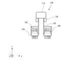
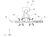
- Embodiment 1 of this invention It is a side view of the agricultural machine which concerns on Embodiment 1 of this invention. It is a front view of the agricultural machine which concerns on Embodiment 1 of this invention. It is a rear view of the agricultural machine which concerns on Embodiment 1 of this invention. It is a top view of the agricultural machine which concerns on Embodiment 1 of this invention.
- the agricultural machine according to the embodiment of the present invention has the following configuration.
- An agricultural machine comprising: a body moving unit for moving the machine, and a fall prevention part connected to the front or the rear of the machine and preventing the machine from falling by at least buoyancy.
- the fall prevention unit is a material containing air inside.
- Item 9 Item 1 of any one of items 1 to 8, wherein the fall prevention unit further includes a front fall prevention unit provided in front of the machine body and a rear fall prevention part provided in the rear of the machine body. Agricultural machinery described in.
- the agricultural machine according to any one of items 1 to 11, further comprising a sensor for detecting the attitude of the machine body, the power source of which is controlled in operation based on data from the sensor.
- the machine body moving portion is a claw wheel having a plurality of claws, the claw wheel is provided in front of and behind the machine body, and the number of claws of the claw wheel provided in the front is provided in the rear.
- the agricultural machine according to any one of items 1 to 13, wherein the number of claws is larger than that of the claw wheel.
- the machine body moving portion is a claw wheel having a plurality of claws, and the claw wheel is provided in front of and behind the machine body, respectively, and the number of rotations of the claw wheel provided in the front is provided in the rear.
- the body moving portion is a claw wheel having a plurality of movable claws, and when the agricultural machine advances in front of the machine body, the movable claws first project with respect to the tangent line of the claw wheel.
- the movable claw is provided at a second protrusion angle with respect to the tangent line of the claw wheel, and the second protrusion angle is the second.
- the agricultural machine according to any one of items 1 to 15, characterized in that the protrusion angle is larger than the protrusion angle of 1 and the second protrusion angle is an blunt angle.
- the agricultural machine 100 will be described by taking the configuration shown in FIG. 1-4 as an example.
- the front-rear direction (length direction) of the agricultural machine 100 will be described as the x-axis direction, the lateral direction (width direction) as the y-axis direction, and the vertical direction (height direction) as the z-axis direction.
- the agricultural machine 100 includes a control unit 110, a frame unit 120, a power source 130, an airframe moving unit 140 (hereinafter, referred to as a claw wheel 140 as a specific example), a claw 150, a fall prevention unit 160, and a fluid resistance. It has a reduction unit 170.
- the entire agricultural machine 100 may be collectively referred to as an airframe.
- the control unit 110 receives a control signal from a controller (not shown) operated by an operator, and receives a control signal from a power source 130 (for example, a motor that uses electricity as fuel, an engine that uses gasoline as fuel, or a motor and an engine). It is possible to move the aircraft forward or backward by operating a hybrid type that operates).
- a controller not shown
- a power source 130 for example, a motor that uses electricity as fuel, an engine that uses gasoline as fuel, or a motor and an engine. It is possible to move the aircraft forward or backward by operating a hybrid type that operates).
- FIG. 5 illustrates the hardware configuration of the control unit 110.
- the control unit 110 is connected to an energy supply source 220 that supplies energy generated from electricity, fuel, or the like to the control unit 110 or the power source 130.
- the energy supply source 220 may be provided inside the control unit 110, or may be provided by being connected to the control unit 110 from the outside. Further, the energy supply source 220 may include means for storing energy (for example, a battery).
- control unit 110 includes at least a power source control unit 210.
- the power source control unit 210 includes a transmission / reception unit 211, a processing unit 212, a storage unit 213, and sensors 214.
- the control unit 110 is configured to receive and / or transmit data from one or more external controllers (eg, transmitter / receiver (propo) 49, terminal, display device, or other remote controller).
- the transmission / reception unit 211 is provided.
- the transmission / reception unit 211 can use any appropriate communication means such as wired communication or wireless communication, but in the case of wired communication, it is necessary to consider the communication cable and the work route, etc. Wireless communication is more preferable in consideration of convenience.
- the processing unit 212 performs data processing based on the data received from the transmission / reception unit 211, the data stored in the storage unit 213 described later, and the data from the sensors 214. For example, the control line connected to the power source 130. A control signal for controlling the power source 130 is transmitted via 230.
- the storage unit 213 stores logic, code, and / or program instructions that can be executed by the control unit 110 to perform one or more steps. Further, the storage unit 213 may include, for example, a separable medium such as an SD card or a random access memory (RAM) or an external storage device. The data acquired from the sensors 214 may be directly transmitted and stored in the storage unit 213.
- Sensors 214 may include inertial sensors (accelerometers, gyro sensors), GPS sensors, proximity sensors (eg, riders), or vision / image sensors (eg, cameras). In particular, it is preferable to provide at least an inertial sensor from the viewpoint of preventing falls. For example, the operation of the power source 130 is adjusted by the processing unit 212 using the data of the inertial sensor (for example, when the load of the power source 130 becomes large). To prevent the power source 130 from tipping over due to inertia (such as weakening the driving force) and inertia.
- inertial sensors accelerometers, gyro sensors
- GPS sensors eg, GPS sensors
- proximity sensors eg, riders
- vision / image sensors eg, cameras
- the operation of the power source 130 is adjusted by the processing unit 212 using the data of the inertial sensor (for example, when the load of the power
- the frame unit 120 supports the control unit 110, the power source 130, the claw wheel 140, the fall prevention unit 160, and the fluid resistance reduction unit 170.
- the frame portion 120 may be configured to further support a configuration (not shown in FIG. 1).
- the power source 130 operates the claw wheel 140, and the specific configuration thereof is described above, for example, a motor using electricity as fuel, an engine using gasoline or the like as fuel, or a motor and an engine in cooperation with each other. It may be in various forms such as a working hybrid type.
- the left and right power sources 130 can control the left and right claw wheels 140 in different rotation directions.
- the left and right claw wheels operated only in the same direction of rotation, so the direction of travel was changed by the handle.
- the direction of travel of the agricultural machine 100 can be changed or on the spot. It becomes easy to rotate with.
- the claw wheel 140 is, for example, a roller-shaped wheel wheel rotated by a power source 130 in which a plurality of claws 150 are projected in a comb-teeth shape, and the claws 150 have a shape bent rearward of the machine body.
- the claw wheel 140 is connected to the power source 130 by, for example, a chain and a gear (not shown), rotates in response to the operation of the power source 130, and moves the machine body forward or backward.
- the shapes of the claw wheel 140 and the claw 150 are not limited as long as they have a middle cultivation function or a herbicidal function.
- the fall prevention unit 160 has a cylindrical shape in which the central portion is hollow in the agricultural machine 100 according to the first embodiment of the present invention.
- the fall prevention portion 160 is made of a material (for example, a foam material) that contains a large amount of air and tends to generate buoyancy. As a result, for example, buoyancy is generated in the water stretched in the paddy field, and it is possible to support the agricultural machine 100 so that it does not fall when it is likely to fall behind the machine. Further, the inside of the fall prevention portion 160 itself may be hollow, and in this case as well, the same effect as described above is obtained.
- the fluid resistance reducing unit 170 may have a shape that reduces the fluid resistance of water or the like to facilitate the progress of the agricultural machine 100, and may have a substantially V-shape or a curved shape such as the bottom of a ship.
- the fall prevention unit 160 it is possible to prevent the machine from falling backward due to, for example, inertia.
- the fall prevention unit 161 has a spherical shape.
- the fall prevention unit 161 may be made of a material containing a large amount of air and easily generating buoyancy, and this configuration has the same effect as that of the first embodiment. Further, the inside of the fall prevention portion 161 itself may be hollow, and this configuration also has the same effect as that of the first embodiment.
- the fall prevention unit 161 is not limited to the sphere as shown in FIG. 6, and may be, for example, a long sphere extending in the y-axis direction, or may have any shape as long as it is a sphere.
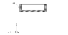
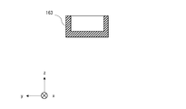
- the fall prevention portion 162 is a flat member (for example, plate-shaped) having a wide bottom surface. Due to this shape, not only the buoyancy but also the surface tension is increased, so that a higher fall prevention effect can be obtained. Further, the fall prevention portion 162 may be made of a material containing a large amount of air and easily generating buoyancy, and this structure has the same effect as that of the first embodiment. Further, the inside of the fall prevention portion 162 itself may be hollow, and this configuration also has the same effect as that of the first embodiment.
- the fall prevention unit 162 may be a cube, but as shown in FIGS. 8 and 9, for example, a cross section (so-called cross section) of a surface perpendicular to the axis (x axis) in the length direction. ) Or the shape of the cross section of the surface perpendicular to the axis in the width direction (y-axis) may be a shape that is open to the upper part, and this configuration provides a higher fall prevention effect. Be done.
- the fall prevention unit 163 has the same or similar outer shape as the fluid resistance reduction unit 170 (for example, a substantially V shape such as the bottom of a ship). Or curved shape). Due to this shape, not only the buoyancy but also the fluid resistance can be reduced when moving to the rear of the aircraft. Further, the fall prevention portion 163 may be made of a material containing a large amount of air and easily generating buoyancy, and this structure has the same effect as that of the first embodiment. Further, the inside of the fall prevention portion 163 itself may be hollow, and this configuration also has the same effect as that of the first embodiment.
- the fall prevention portion 163 may have a flat upper surface portion, but as shown in FIGS. 11 and 12, for example, a cross section of a surface perpendicular to the axis (x axis) in the length direction.
- the shape of the cross section of the surface perpendicular to the axis (y-axis) in the width direction may be a shape that is open to the upper portion, and this configuration can obtain a higher fall prevention effect. ..
- the fall prevention portion 163 may have a shape having at least an effect of reducing fluid resistance
- the upper surface portion may have a flat shape, but as shown in FIGS. 11 and 12, for example, the length is long.
- the shape of the cross section of the surface perpendicular to the vertical axis (x axis) and the shape of the cross section of the surface perpendicular to the width direction axis (y axis) are shapes that are open to the upper part. However, with this configuration, a higher fall prevention effect can be obtained.
- the agricultural machine 100 includes a front fall prevention unit 164 provided in front of the machine body and a rear fall prevention part 165 provided in the rear of the machine body.
- a fall prevention effect can be obtained in both the front and rear directions.
- a columnar rear fall prevention portion 165 as in the first embodiment is provided, and a part of the fluid resistance reducing portion 170 is similarly cylindrical in front.
- a fall prevention unit 164 is provided.
- the front fall prevention unit 164 and the rear fall prevention unit 165 may be combined by appropriately selecting the shapes described in the first to fourth embodiments, or the fluid resistance reduction unit 170 may not be attached.
- the front fall prevention unit 164 and the rear fall prevention unit 165 have at least the shape, size, material, and buoyancy. Any one may be different from each other.
- the operation control by the controller is illustrated, but the same problem (for example, the progress is hindered by soil or mud and the vehicle falls in the direction of travel) is also encountered in the operation with the handle. If so, this is also applicable.
- a paddy field middle-cultivation herbicide is illustrated, but the present invention is not limited to this, and a field-use middle-cultivation machine may be used. In that case, not buoyancy but physical overturning can be suppressed. That's fine.
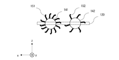
- the number of comb-shaped claws 151 of the front claw wheel 141 is larger than the number of comb-shaped claws 152 of the rear claw wheel 142.
- the rear body moving portion is, for example, a roller-shaped car rotated by a power source 130, and a plurality of plate-shaped blades.
- the impeller 143 When the impeller 143 is a projecting impeller 153 and the blade 153 is bent rearward of the machine body, it is the front claw wheel 141 that exerts a substantial weeding effect, so that a higher weeding effect can be obtained. It becomes.
- the number of comb-shaped claws 151 is double the number of comb-shaped claws 152 for ease of explanation, but the number is not limited to this.
- the fall prevention unit is not shown for the sake of simplicity, but in the sixth embodiment of the present invention, the presence or absence of the fall prevention unit may be in any form.
- a plurality of power sources are individually provided for the front claw wheel 141 and the rear claw wheel 142, or the gear ratio of the gears connected to the chain is changed between the front and rear claw wheels. Therefore, the same effect may be obtained by increasing the rotation speed of the front claw wheel 141 to be higher than the rotation speed of the rear claw wheel 142.
- the agricultural machine 100 includes a claw wheel 144 having a plurality of movable claws 154.
- the movable portion 181 slides the elongated hole 182 with the fixed portion 180 as the center of rotation, and the claws are clawed.
- the first protrusion angle ⁇ which is the angle formed by the tangent of the car 144 and the movable claw 154 on the front side of the machine body, is an obtuse angle.
- FIG. 16A when moving forward, the movable portion 181 slides the elongated hole 182 with the fixed portion 180 as the center of rotation, and the claws are clawed.
- the first protrusion angle ⁇ which is the angle formed by the tangent of the car 144 and the movable claw 154 on the front side of the machine body, is an obtuse angle.
- FIG. 16A when moving forward, the movable portion 181 slides the elongated hole 182 with the fixed portion 180 as the center of rotation, and the claws are claw
- the movable part 181 slides the obtuse hole 182 with the fixed part 180 as the center of rotation, and is movable with the tangent line of the claw wheel 144.
- the second protrusion angle ⁇ ' which is the angle formed by the claw 154 on the rear side of the machine body, becomes an obtuse angle.
- the protrusion angle is obtuse so as to reduce the resistance applied to the claws and the claw wheel.
- the position of the movable claw is changed so as to be. It should be noted that the above-mentioned effect is particularly obtained when the agricultural machine is a paddy field weeder or when the shape of the claw is bent to the rear of the machine, but the present invention is not limited to this.
Landscapes
- Life Sciences & Earth Sciences (AREA)
- Engineering & Computer Science (AREA)
- Mechanical Engineering (AREA)
- Soil Sciences (AREA)
- Environmental Sciences (AREA)
- Soil Working Implements (AREA)
- Guiding Agricultural Machines (AREA)
- Catching Or Destruction (AREA)
Priority Applications (3)
| Application Number | Priority Date | Filing Date | Title |
|---|---|---|---|
| JP2021540945A JP7090304B2 (ja) | 2019-08-21 | 2020-08-18 | 農業機械 |
| JP2021207810A JP7045677B2 (ja) | 2019-08-21 | 2021-12-22 | 農業機械 |
| JP2021207809A JP7090850B2 (ja) | 2019-08-21 | 2021-12-22 | 農業機械 |
Applications Claiming Priority (2)
| Application Number | Priority Date | Filing Date | Title |
|---|---|---|---|
| JP2019151600 | 2019-08-21 | ||
| JP2019-151600 | 2019-08-21 |
Publications (1)
| Publication Number | Publication Date |
|---|---|
| WO2021033674A1 true WO2021033674A1 (ja) | 2021-02-25 |
Family
ID=74661007
Family Applications (1)
| Application Number | Title | Priority Date | Filing Date |
|---|---|---|---|
| PCT/JP2020/031058 Ceased WO2021033674A1 (ja) | 2019-08-21 | 2020-08-18 | 農業機械 |
Country Status (2)
| Country | Link |
|---|---|
| JP (3) | JP7090304B2 (https=) |
| WO (1) | WO2021033674A1 (https=) |
Cited By (1)
| Publication number | Priority date | Publication date | Assignee | Title |
|---|---|---|---|---|
| CN115211251A (zh) * | 2022-08-12 | 2022-10-21 | 华南农业大学 | 一种应用于水田上的行走除草装置及行走除草底盘 |
Citations (7)
| Publication number | Priority date | Publication date | Assignee | Title |
|---|---|---|---|---|
| JP2005065664A (ja) * | 2003-08-20 | 2005-03-17 | Yasutoshi Iwase | 農業管理ロボット |
| JP2007189907A (ja) * | 2006-01-17 | 2007-08-02 | Toyoji Aida | 浮遊分離爪を備えた水田用トラクタ。 |
| JP2007244337A (ja) * | 2006-03-17 | 2007-09-27 | Ishii Seisakusho:Kk | 湿田用被牽引装置 |
| JP2011120573A (ja) * | 2009-11-10 | 2011-06-23 | Ikoma Robotech Corp | 水田除草ロボット |
| JP2012187073A (ja) * | 2011-03-14 | 2012-10-04 | Shimane Prefecture | 水田用の除草作業機 |
| JP2015043718A (ja) * | 2013-08-28 | 2015-03-12 | Ikomaロボテック株式会社 | 稲株認識センサ、及び稲株認識センサを搭載した水田除草ロボット |
| JP2016152775A (ja) * | 2015-02-20 | 2016-08-25 | 菱農エンジニアリング株式会社 | 自律走行水田除草機 |
Family Cites Families (5)
| Publication number | Priority date | Publication date | Assignee | Title |
|---|---|---|---|---|
| JP2002034305A (ja) * | 2000-07-31 | 2002-02-05 | Toyoji Aida | 水田除草機 |
| JP2002084813A (ja) * | 2000-09-11 | 2002-03-26 | Toyoji Aida | 水田除草機 |
| JP6260951B2 (ja) * | 2013-09-12 | 2018-01-17 | 公立大学法人会津大学 | 水田除草ロボット |
| JP6606356B2 (ja) * | 2015-06-03 | 2019-11-13 | Ikomaロボテック株式会社 | 水田除草ロボット |
| CN206948827U (zh) * | 2017-04-25 | 2018-02-02 | 李春辉 | 一种水田中耕除草机 |
-
2020
- 2020-08-18 WO PCT/JP2020/031058 patent/WO2021033674A1/ja not_active Ceased
- 2020-08-18 JP JP2021540945A patent/JP7090304B2/ja not_active Expired - Fee Related
-
2021
- 2021-12-22 JP JP2021207809A patent/JP7090850B2/ja not_active Expired - Fee Related
- 2021-12-22 JP JP2021207810A patent/JP7045677B2/ja not_active Expired - Fee Related
Patent Citations (7)
| Publication number | Priority date | Publication date | Assignee | Title |
|---|---|---|---|---|
| JP2005065664A (ja) * | 2003-08-20 | 2005-03-17 | Yasutoshi Iwase | 農業管理ロボット |
| JP2007189907A (ja) * | 2006-01-17 | 2007-08-02 | Toyoji Aida | 浮遊分離爪を備えた水田用トラクタ。 |
| JP2007244337A (ja) * | 2006-03-17 | 2007-09-27 | Ishii Seisakusho:Kk | 湿田用被牽引装置 |
| JP2011120573A (ja) * | 2009-11-10 | 2011-06-23 | Ikoma Robotech Corp | 水田除草ロボット |
| JP2012187073A (ja) * | 2011-03-14 | 2012-10-04 | Shimane Prefecture | 水田用の除草作業機 |
| JP2015043718A (ja) * | 2013-08-28 | 2015-03-12 | Ikomaロボテック株式会社 | 稲株認識センサ、及び稲株認識センサを搭載した水田除草ロボット |
| JP2016152775A (ja) * | 2015-02-20 | 2016-08-25 | 菱農エンジニアリング株式会社 | 自律走行水田除草機 |
Cited By (2)
| Publication number | Priority date | Publication date | Assignee | Title |
|---|---|---|---|---|
| CN115211251A (zh) * | 2022-08-12 | 2022-10-21 | 华南农业大学 | 一种应用于水田上的行走除草装置及行走除草底盘 |
| CN115211251B (zh) * | 2022-08-12 | 2024-02-02 | 华南农业大学 | 一种应用于水田上的行走除草装置及行走除草底盘 |
Also Published As
| Publication number | Publication date |
|---|---|
| JP7045677B2 (ja) | 2022-04-01 |
| JP7090304B2 (ja) | 2022-06-24 |
| JP2022033209A (ja) | 2022-02-28 |
| JP7090850B2 (ja) | 2022-06-27 |
| JPWO2021033674A1 (https=) | 2021-02-25 |
| JP2022033208A (ja) | 2022-02-28 |
Similar Documents
| Publication | Publication Date | Title |
|---|---|---|
| JP7550281B2 (ja) | 自動走行システム及び自動走行方法 | |
| JP6663366B2 (ja) | 経路生成システム、及びそれによって生成された経路に沿って作業車両を走行させる自律走行システム | |
| JP6860387B2 (ja) | 作業車 | |
| JP6294839B2 (ja) | 圃場管理システム | |
| JP2016011024A (ja) | 植播系圃場作業機 | |
| JP2018092401A (ja) | 経路生成システム | |
| JP6658717B2 (ja) | 作業車両 | |
| JP2016024540A (ja) | 走行作業機及びそれに用いられる自動操舵システム | |
| JP2020068693A (ja) | 表示装置、及び、自動走行システム | |
| JP2017127292A (ja) | 農業用作業車両 | |
| JP7150593B2 (ja) | 作業車両 | |
| JP6863193B2 (ja) | 作業車両 | |
| JP7045677B2 (ja) | 農業機械 | |
| JP6677286B2 (ja) | 作業車両および作業車両の自動直進走行支援システム | |
| JP7102333B2 (ja) | 作業車両の制御装置及び制御装置を備えた作業車両 | |
| JP2020101964A (ja) | 走行状態表示装置、及び、自動走行システム | |
| JP7488759B2 (ja) | 経路生成システム | |
| JP2019175049A (ja) | 作業車両の自動走行装置 | |
| JP7269811B2 (ja) | 自動走行システム | |
| JP7229119B2 (ja) | 自動走行システム | |
| US20250374847A1 (en) | Travel assistance system and method of creating route | |
| JP6877709B1 (ja) | 水田除草機、制御方法、プログラム | |
| JP2020147205A (ja) | 自動走行システム | |
| JP7627294B2 (ja) | 経路生成システム及び経路生成方法 | |
| JP2022049380A (ja) | 自動運転支援装置 |
Legal Events
| Date | Code | Title | Description |
|---|---|---|---|
| 121 | Ep: the epo has been informed by wipo that ep was designated in this application |
Ref document number: 20854868 Country of ref document: EP Kind code of ref document: A1 |
|
| ENP | Entry into the national phase |
Ref document number: 2021540945 Country of ref document: JP Kind code of ref document: A |
|
| NENP | Non-entry into the national phase |
Ref country code: DE |
|
| 122 | Ep: pct application non-entry in european phase |
Ref document number: 20854868 Country of ref document: EP Kind code of ref document: A1 |