WO2021029214A1 - 切削工具、切削工具用ホルダ、工具システム、通信方法および旋削用工具 - Google Patents
切削工具、切削工具用ホルダ、工具システム、通信方法および旋削用工具 Download PDFInfo
- Publication number
- WO2021029214A1 WO2021029214A1 PCT/JP2020/028800 JP2020028800W WO2021029214A1 WO 2021029214 A1 WO2021029214 A1 WO 2021029214A1 JP 2020028800 W JP2020028800 W JP 2020028800W WO 2021029214 A1 WO2021029214 A1 WO 2021029214A1
- Authority
- WO
- WIPO (PCT)
- Prior art keywords
- measurement
- sensor
- state
- wireless communication
- communication unit
- Prior art date
Links
Images


Classifications
-
- B—PERFORMING OPERATIONS; TRANSPORTING
- B23—MACHINE TOOLS; METAL-WORKING NOT OTHERWISE PROVIDED FOR
- B23B—TURNING; BORING
- B23B27/00—Tools for turning or boring machines; Tools of a similar kind in general; Accessories therefor
-
- B—PERFORMING OPERATIONS; TRANSPORTING
- B23—MACHINE TOOLS; METAL-WORKING NOT OTHERWISE PROVIDED FOR
- B23B—TURNING; BORING
- B23B29/00—Holders for non-rotary cutting tools; Boring bars or boring heads; Accessories for tool holders
- B23B29/04—Tool holders for a single cutting tool
- B23B29/12—Special arrangements on tool holders
-
- B—PERFORMING OPERATIONS; TRANSPORTING
- B23—MACHINE TOOLS; METAL-WORKING NOT OTHERWISE PROVIDED FOR
- B23Q—DETAILS, COMPONENTS, OR ACCESSORIES FOR MACHINE TOOLS, e.g. ARRANGEMENTS FOR COPYING OR CONTROLLING; MACHINE TOOLS IN GENERAL CHARACTERISED BY THE CONSTRUCTION OF PARTICULAR DETAILS OR COMPONENTS; COMBINATIONS OR ASSOCIATIONS OF METAL-WORKING MACHINES, NOT DIRECTED TO A PARTICULAR RESULT
- B23Q11/00—Accessories fitted to machine tools for keeping tools or parts of the machine in good working condition or for cooling work; Safety devices specially combined with or arranged in, or specially adapted for use in connection with, machine tools
-
- B—PERFORMING OPERATIONS; TRANSPORTING
- B23—MACHINE TOOLS; METAL-WORKING NOT OTHERWISE PROVIDED FOR
- B23Q—DETAILS, COMPONENTS, OR ACCESSORIES FOR MACHINE TOOLS, e.g. ARRANGEMENTS FOR COPYING OR CONTROLLING; MACHINE TOOLS IN GENERAL CHARACTERISED BY THE CONSTRUCTION OF PARTICULAR DETAILS OR COMPONENTS; COMBINATIONS OR ASSOCIATIONS OF METAL-WORKING MACHINES, NOT DIRECTED TO A PARTICULAR RESULT
- B23Q17/00—Arrangements for observing, indicating or measuring on machine tools
- B23Q17/09—Arrangements for observing, indicating or measuring on machine tools for indicating or measuring cutting pressure or for determining cutting-tool condition, e.g. cutting ability, load on tool
-
- B—PERFORMING OPERATIONS; TRANSPORTING
- B23—MACHINE TOOLS; METAL-WORKING NOT OTHERWISE PROVIDED FOR
- B23Q—DETAILS, COMPONENTS, OR ACCESSORIES FOR MACHINE TOOLS, e.g. ARRANGEMENTS FOR COPYING OR CONTROLLING; MACHINE TOOLS IN GENERAL CHARACTERISED BY THE CONSTRUCTION OF PARTICULAR DETAILS OR COMPONENTS; COMBINATIONS OR ASSOCIATIONS OF METAL-WORKING MACHINES, NOT DIRECTED TO A PARTICULAR RESULT
- B23Q17/00—Arrangements for observing, indicating or measuring on machine tools
- B23Q17/12—Arrangements for observing, indicating or measuring on machine tools for indicating or measuring vibration
Definitions
- the present disclosure relates to cutting tools, cutting tool holders, tool systems, communication methods and turning tools.
- This application claims priority on the basis of Japanese Application Japanese Patent Application No. 2019-147395 filed on August 9, 2019, and incorporates all of its disclosures herein.
- Patent Document 1 Japanese Unexamined Patent Publication No. 2014-46407 discloses the following cutting tools. That is, the cutting tool includes a cutting edge processing portion in which the cutting edge treatment is performed in the region connecting the flank surface and the rake face, and a cutting edge ridge line formed at the boundary between the cutting edge processing portion and the flank surface.
- the width of the cutting tool is the shortest distance connecting the boundary between the cutting edge processing portion and the rake face and the cutting edge ridge line when the cutting tool is viewed in a plan view from the rake face side.
- a groove along the cutting edge ridge line involved in cutting is provided in a region from the boundary between the cutting edge processing section and the rake face to 90% of the width of the cutting edge processing section.
- the cutting tool of the present disclosure is a cutting tool including a cutting insert having a cutting edge, a holder for holding the cutting insert, and a battery, a measurement sensor, and a wireless communication unit provided in the holder.
- the communication unit is driven by the power supplied from the battery and wirelessly transmits measurement information including the measurement result of the measurement sensor or information based on the measurement result.
- the tool system of the present disclosure includes a cutting insert having a cutting edge, a holder for holding the cutting insert, and a cutting tool provided in the holder including a battery, a measuring sensor, and a wireless communication unit, and a management device.
- the cutting tool wirelessly transmits measurement information including a measurement result of the measurement sensor or information based on the measurement result to the management device.
- the communication method of the present disclosure includes a cutting insert having a cutting edge, a holder for holding the cutting insert, and a cutting tool provided in the holder including a battery, a measuring sensor, and a wireless communication unit, and a tool including a management device.
- a communication method in the system, wherein the management device and the cutting tool provide measurement information including a step of establishing a communication connection and the cutting tool a measurement result of the measurement sensor or information based on the measurement result. Includes a step of wireless transmission to the management device.
- the turning tool of the present disclosure includes a cutting insert having a cutting edge, a holder for holding the cutting insert, and a battery, a measurement sensor, a start sensor, a memory, and a wireless communication unit provided in the holder for turning.
- a tool the battery supplies power to the measurement sensor, the activation sensor, the memory and the wireless communication unit, the measurement sensor includes an acceleration sensor or a strain sensor, and the activation sensor is a proximity sensor.
- Distance sensor, ultrasonic sensor, photoelectric sensor, laser sensor, temperature sensor and illuminance sensor, and the wireless communication unit includes the measurement result of the measurement sensor or information based on the measurement result. Radio transmission of measurement information.
- the holder for a cutting tool of the present disclosure includes a holding unit for holding a cutting insert, a battery, a measurement sensor, and a wireless communication unit.
- the wireless communication unit is driven by power supplied from the battery, and the measurement sensor is driven.
- the measurement information including the measurement result of the above or the information based on the measurement result is transmitted wirelessly.
- One aspect of the present disclosure can be realized as a semiconductor integrated circuit that realizes a part or all of a cutting tool. Further, one aspect of the present disclosure can be realized as a semiconductor integrated circuit that realizes a part or all of a turning tool. Further, one aspect of the present disclosure can be realized as a semiconductor integrated circuit that realizes a part or all of a tool system. Further, one aspect of the present disclosure can be realized as a program for causing a computer to execute a processing step in a communication method. Further, one aspect of the present disclosure can be realized as a semiconductor integrated circuit that realizes a part or all of a holder for a cutting tool.
- FIG. 1 is a diagram showing a configuration of a tool system according to an embodiment of the present disclosure.
- FIG. 2 is a diagram showing an example of a sensor packet transmitted by the cutting tool according to the embodiment of the present disclosure.
- FIG. 3 is a cross-sectional view showing another example of the configuration of the cutting tool according to the embodiment of the present disclosure.
- FIG. 4 is a diagram showing a configuration of a management device according to an embodiment of the present disclosure.
- FIG. 5 is a diagram showing a configuration of a sensor module according to the embodiment of the present disclosure.
- FIG. 6 is a diagram showing an example of the format of the advertisement packet transmitted by the management device in the tool system according to the embodiment of the present disclosure.
- FIG. 1 is a diagram showing a configuration of a tool system according to an embodiment of the present disclosure.
- FIG. 2 is a diagram showing an example of a sensor packet transmitted by the cutting tool according to the embodiment of the present disclosure.
- FIG. 3 is a cross-sectional view showing another example of
- FIG. 7 is a flowchart defining an example of an operation procedure when the cutting tool transmits a sensor packet to the management device in the tool system according to the embodiment of the present disclosure.
- FIG. 8 is a flowchart defining another example of the operation procedure when the cutting tool transmits a sensor packet to the management device in the tool system according to the embodiment of the present disclosure.
- FIG. 9 is a flowchart defining another example of the operation procedure when the cutting tool transmits a sensor packet to the management device in the tool system according to the embodiment of the present disclosure.
- FIG. 10 is a diagram showing an example of a sequence of communication processing in the tool system according to the embodiment of the present disclosure.
- FIG. 11 is a diagram showing an example of a sequence of communication processing in the tool system according to the embodiment of the present disclosure.
- the present disclosure has been made to solve the above-mentioned problems, and the purpose of the present disclosure is to realize cutting tools, cutting tool holders, tool systems, and communications capable of realizing excellent functions for predicting the life of cutting tools. To provide a method and a turning tool.
- the cutting tool includes a cutting insert having a cutting edge, a holder for holding the cutting insert, and a battery, a measurement sensor, and a wireless communication unit provided in the holder.
- a cutting tool, the wireless communication unit is driven by the power supplied from the battery, and wirelessly transmits measurement information including a measurement result of the measurement sensor or information based on the measurement result.
- the cutting tool and an external device such as a management device can be connected by wire, or the cutting tool can be connected to the cutting tool by wirelessly transmitting the measurement result of the measurement sensor provided in the holder or the measurement information including the information based on the measurement result.
- the measurement information can be transmitted to the external device without connecting to the processing machine by wire. Therefore, it is possible to realize an excellent function regarding the prediction of the life of the cutting tool.
- the cutting tool further includes a control unit provided in the holder, and the control unit wirelessly transmits the measurement information to the wireless communication unit, and the measurement information. It is possible to switch to the non-reporting state without wireless transmission.
- the configuration that can switch between the reporting state and the non-reporting state of the wireless communication unit can reduce the power consumption required for wirelessly transmitting the measurement information and reduce the frequency of battery replacement or charging. At the same time, it is possible to suppress an increase in wireless traffic.
- the cutting tool further includes a control unit provided in the holder, and the control unit can switch the measurement sensor between a measurement state and a non-measurement state.
- the configuration that can switch between the measurement state and the non-measurement state of the measurement sensor can suppress the power consumption by the measurement sensor and reduce the frequency of battery replacement or charging.
- control unit can switch the measurement sensor between a measurement state and a non-measurement state.
- the configuration that can switch between the measurement state and the non-measurement state of the measurement sensor can suppress the power consumption by the measurement sensor and reduce the frequency of battery replacement or charging.
- the wireless communication unit in the non-reporting state, periodically transitions to a state in which an instruction from the outside of the cutting tool can be received, and the wireless communication unit is the control unit. Upon receiving the instruction, the wireless communication unit is switched from the non-reporting state to the reporting state, and the measurement sensor is switched from the non-measuring state to the measuring state.
- the wireless communication unit can be switched from the non-reporting state to the reporting state, and the measurement sensor can be switched from the non-measuring state to the measuring state, for example, by using an instruction from an external device such as a management device as a trigger.
- the wireless communication unit is required to receive the instruction regarding switching between the states of the wireless communication unit and the measurement sensor from the outside by the configuration that periodically transitions to the state in which the instruction can be received in the non-reporting state. It is possible to reduce power consumption.
- the cutting tool further includes a start sensor provided in the holder, and the control unit sets the wireless communication unit when the measurement result of the start sensor satisfies the first condition. At the same time as switching from the non-reporting state to the reporting state, the measurement sensor is switched from the non-measuring state to the measuring state.
- the states of the wireless communication unit and the measurement sensor can be switched using the measurement result of the activation sensor as a trigger. Therefore, the trigger for switching the states of the wireless communication unit and the measurement sensor is from the outside of the cutting tool. No reception is required. Further, as the start sensor, for example, by using a sensor that consumes less current than the measurement sensor or by intermittently driving the start sensor, the power required to acquire the timing for switching the state of the wireless communication unit and the measurement sensor is obtained. Can reduce the consumption of.
- the control unit stops the activation sensor, and the control unit receives the measurement information from the wireless communication unit. After wireless transmission, the wireless communication unit is switched from the reported state to the non-reported state, and the measurement sensor is switched from the measured state to the non-measured state.
- the wireless communication unit can be switched to the non-reporting state and the measurement sensor can be switched to the non-measuring state while reducing the power consumption of the activation sensor.
- the control unit switches the wireless communication unit from the reporting state to the non-reporting state, and switches the measurement sensor from the measuring state to the non-reporting state. Switch to the measurement state.
- the wireless communication unit can be switched from the reporting state to the non-reporting state, and the measurement sensor can be switched from the measuring state to the non-measuring state, for example, by using an instruction from an external device such as a management device as a trigger.
- control unit switches the wireless communication unit from the reporting state to the non-reporting state, and switches the measurement sensor to the non-reporting state.
- the measurement state is switched to the non-measurement state.
- the wireless communication unit can be switched from the reporting state to the non-reporting state and the measurement sensor can be switched from the measuring state to the non-measuring state by using the measurement result of the activation sensor as a trigger. It is not necessary to receive the trigger related to the switching of the sensor state from the outside of the cutting tool.
- the tool system includes a cutting insert having a cutting edge, a holder for holding the cutting insert, and a cutting tool provided in the holder including a battery, a measuring sensor, and a wireless communication unit.
- the cutting tool wirelessly transmits measurement information including the measurement result of the measurement sensor or information based on the measurement result to the management device.
- the cutting tool can be connected by wire to the management device by wirelessly transmitting the measurement result of the measurement sensor provided in the holder or the measurement information including the information based on the measurement result to the management device.
- Measurement information can be transmitted to the management device without connecting the cutting tool and the processing machine by wire. Therefore, it is possible to realize an excellent function regarding the prediction of the life of the cutting tool.
- the management device transmits a transmission start instruction indicating that the transmission of the measurement information should be started to the cutting tool, and when the cutting tool receives the transmission start instruction, the measurement information Start wireless transmission.
- the cutting tool can start wireless transmission of measurement information by using the transmission start instruction received from the management device as a trigger. Therefore, the cutting tool itself detects the trigger for starting the transmission start instruction.
- the configuration of is unnecessary.
- the cutting tool further includes a start sensor provided in the holder and a control unit provided in the holder, and the control unit measures the measurement sensor in a measurement state and a non-measurement state.
- the wireless communication unit can be switched between a reporting state in which the measurement information is wirelessly transmitted to the management device and a non-reporting state in which the measurement information is not wirelessly transmitted.
- the wireless communication unit is switched from the non-reporting state to the reporting state, and the measurement sensor is switched from the non-measuring state to the measuring state.
- the configuration in which the reporting state and the non-reporting state of the wireless communication unit can be switched and the measuring state and the non-measurement state of the measurement sensor can be switched It is possible to reduce power consumption, reduce the frequency of battery replacement or charging, and suppress an increase in wireless traffic.
- the state of the wireless communication unit and the measurement sensor can be switched using the measurement result of the activation sensor as a trigger, it is not necessary to receive the trigger related to the switching of the state of the wireless communication unit and the measurement sensor from the outside of the cutting tool. Become.
- the power required to acquire the timing for switching the state of the wireless communication unit and the measurement sensor is obtained. Can reduce the consumption of.
- the control unit stops the activation sensor, and the control unit manages the measurement information by the wireless communication unit. After transmitting to the device, the wireless communication unit is switched from the reporting state to the non-reporting state, and the measurement sensor is switched from the measuring state to the non-measuring state.
- the wireless communication unit can be switched to the non-reporting state and the measurement sensor can be switched to the non-measuring state while reducing the power consumption of the activation sensor.
- the control unit switches the wireless communication unit from the reporting state to the non-reporting state, and measures the measurement sensor. The state is switched to the non-measurement state.
- the wireless communication unit can be switched from the reporting state to the non-reporting state and the measurement sensor can be switched from the measuring state to the non-measuring state by using the instruction from the management device as a trigger.
- control unit switches the wireless communication unit from the reporting state to the non-reporting state, and switches the measurement sensor to the non-reporting state.
- the measurement state is switched to the non-measurement state.
- the wireless communication unit can be switched from the reporting state to the non-reporting state and the measurement sensor can be switched from the measuring state to the non-measuring state by using the measurement result of the activation sensor as a trigger. It is not necessary to receive the trigger related to the switching of the sensor state from the outside of the cutting tool.
- the communication method includes a cutting insert having a cutting edge, a holder for holding the cutting insert, and a cutting tool provided in the holder including a battery, a measuring sensor, and a wireless communication unit. And a communication method in a tool system including a management device, wherein the management device and the cutting tool establish a communication connection, and the cutting tool is based on the measurement result of the measurement sensor or the measurement result.
- the step includes wirelessly transmitting measurement information including information to the management device.
- the cutting tool can connect the cutting tool and the management device by wire by a method of wirelessly transmitting the measurement result of the measurement sensor provided in the holder or the measurement information including the information based on the measurement result to the management device.
- Measurement information can be transmitted to the management device without connecting the cutting tool and the processing machine by wire. Therefore, it is possible to realize an excellent function regarding the prediction of the life of the cutting tool.
- the turning tool includes a cutting insert having a cutting edge, a holder for holding the cutting insert, a battery, a measurement sensor, a start sensor, a memory, and a battery, a measurement sensor, a start sensor, and a memory provided in the holder.
- a turning tool including a wireless communication unit, wherein the battery supplies power to the measurement sensor, the activation sensor, the memory, and the wireless communication unit, and the measurement sensor is at least an acceleration sensor and a strain sensor.
- the activation sensor includes at least one of a proximity sensor, a distance sensor, an ultrasonic sensor, a photoelectric sensor, a laser sensor, a temperature sensor, and an illuminance sensor, and the wireless communication unit includes any one.
- the measurement information including the measurement result of the measurement sensor or the information based on the measurement result is transmitted wirelessly.
- the turning tool and the external device such as the management device can be connected by wire or used for turning.
- the measurement information can be transmitted to the external device without connecting the tool and the processing machine by wire. Therefore, it is possible to realize an excellent function regarding the prediction of the life of the cutting tool.
- the turning tool further includes a control unit provided in the holder, and the control unit can switch the measurement sensor between a measurement state and a non-measurement state, and the wireless communication.
- the unit can be switched between a reporting state in which the measurement information is wirelessly transmitted and a non-reporting state in which the measurement information is not transmitted wirelessly, and the control unit has a predetermined control unit in which the measurement result of the activation sensor is stored in the memory.
- the wireless communication unit is switched from the non-reporting state to the reporting state, and the measurement sensor is switched from the non-measuring state to the measuring state.
- the configuration in which the reporting state and the non-reporting state of the wireless communication unit can be switched and the measuring state and the non-measurement state of the measurement sensor can be switched It is possible to reduce power consumption, reduce the frequency of battery replacement or charging, and suppress an increase in wireless traffic.
- the state of the wireless communication unit and the measurement sensor can be switched using the measurement result of the activation sensor as a trigger, it is not necessary to receive the trigger related to the switching of the state of the wireless communication unit and the measurement sensor from the outside of the turning tool. It becomes.
- the power required to acquire the timing for switching the state of the wireless communication unit and the measurement sensor is obtained. Can reduce the consumption of.
- the holder for a cutting tool includes a holding unit for holding a cutting insert, a battery, a measurement sensor, and a wireless communication unit, and the wireless communication unit is supplied from the battery. It is driven by electric power and wirelessly transmits measurement information including the measurement result of the measurement sensor or information based on the measurement result.
- the cutting tool and an external device such as a management device can be connected by wire by the configuration of wirelessly transmitting the measurement result of the measurement sensor provided in the holder for the cutting tool or the measurement information including the information based on the measurement result.
- the measurement information can be transmitted to the external device without connecting the cutting tool and the processing machine by wire. Therefore, it is possible to realize an excellent function regarding the prediction of the life of the cutting tool.
- the cutting tool holder further includes a control unit, and the control unit wirelessly transmits the measurement information to the wireless communication unit, and does not transmit the measurement information wirelessly. It is possible to switch to the reporting state.
- the configuration that can switch between the reporting state and the non-reporting state of the wireless communication unit can reduce the power consumption required for wirelessly transmitting the measurement information and reduce the frequency of battery replacement or charging. At the same time, it is possible to suppress an increase in wireless traffic.
- control unit can switch the measurement sensor between a measurement state and a non-measurement state.
- the configuration that can switch between the measurement state and the non-measurement state of the measurement sensor can suppress the power consumption by the measurement sensor and reduce the frequency of battery replacement or charging.
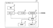
- FIG. 1 is a diagram showing a configuration of a tool system according to an embodiment of the present disclosure.
- the tool system 300 includes a cutting tool 100, a management device 200, and a wireless master unit 201.
- the cutting tool 100 includes a cutting tool holder 2 and a sensor module 110.
- the sensor module 110 includes a measurement sensor.
- the holder 2 for a cutting tool is also simply referred to as a holder 2.
- the wireless master unit 201 is connected to the management device 200, for example, by wire.
- the wireless master unit 201 is, for example, an access point.
- the cutting tool 100 is, for example, a tool for turning and is attached to a turning machine.
- the holder 2 holds a cutting insert 1 having a cutting edge.
- the sensor module 110 is provided in the holder 2.
- the holder 2 includes fixing members 3A and 3B.
- the fixing members 3A and 3B hold the cutting insert 1.
- the fixing members 3A and 3B are examples of the holding portion.
- the cutting insert 1 has a polygonal shape such as a triangle, a square, a rhombus, and a pentagon when viewed from above.
- the cutting insert 1 has, for example, a through hole formed in the center of the upper surface thereof, and is fixed to the holder 2 by the fixing members 3A and 3B.
- the tool system 300 is not limited to the configuration including one cutting tool 100, and may be configured to include a plurality of cutting tools 100. Further, the tool system 300 is not limited to the configuration including one management device 200, and may be configured to include a plurality of management devices 200.
- the cutting tool 100 wirelessly transmits measurement information including the measurement result of the measurement sensor in the sensor module 110 to the wireless master unit 201. Alternatively, the cutting tool 100 wirelessly transmits measurement information including information based on the measurement result of the measurement sensor in the sensor module 110 to the wireless master unit 201.
- the cutting tool 100 wirelessly transmits a sensor packet including measurement information to the wireless master unit 201.
- the cutting tool 100 and the wireless master unit 201 are, for example, compliant with ZigBee (registered trademark) compliant with IEEE 802.15.4, Bluetooth® compliant with IEEE 802.15.1, and IEEE 802.15.3a.
- Wireless communication is performed using a communication protocol such as UWB (Ultra Wide Band).
- UWB Ultra Wide Band
- a communication protocol other than the above may be used between the cutting tool 100 and the wireless master unit 201.
- the wireless master unit 201 relays the sensor packet received from the cutting tool 100 to the management device 200.
- FIG. 2 is a diagram showing an example of a sensor packet transmitted by the cutting tool according to the embodiment of the present disclosure.
- the sensor module 110 in the cutting tool 100 creates a sensor packet 401 in which the measurement information and the sensor ID, which is the ID of the measurement sensor, are stored in the “sensor data” field.
- a predetermined preamble is stored in the field of the "synchronization header" in the sensor packet 401.
- the field of "MAC (Media Access Control) header for example, the MAC address of the sensor module 110 and the like are stored.
- the data length of the "sensor data” field is 20 octets in FIG. 2, but it can be changed according to the type of physical quantity included in the measurement information, the number of the physical quantity, and the like.
- the wireless master unit 201 acquires a sensor packet included in the wireless signal received from the cutting tool 100 and transmits it to the management device 200.
- FIG. 3 is a cross-sectional view showing another example of the configuration of the cutting tool according to the embodiment of the present disclosure.
- the cutting tool 100 may be a tool for milling that is attached to the milling machine. More specifically, the cutting tool 100 for milling includes a holder 2A for holding a plurality of cutting inserts 1A having a cutting edge, and a sensor module 110 provided on the holder 2A including a measuring sensor.
- the holder 2A includes a fixing member 3C.
- the fixing member 3C holds the cutting insert 1A.
- the cutting insert 1A is fixed to the holder 2A by, for example, the fixing member 3C.
- the fixing member 3C is an example of a holding portion.
- FIG. 4 is a diagram showing a configuration of a management device according to an embodiment of the present disclosure.
- the management device 200 includes a communication unit 210, a processing unit 220, and a storage unit 230.
- the storage unit 230 is, for example, a flash memory.
- the communication unit 210 When the communication unit 210 receives the sensor packet from the cutting tool 100 via the wireless master unit 201, the communication unit 210 acquires measurement information and the sensor ID from the received sensor packet, and outputs the acquired measurement information and the sensor ID to the processing unit 220.
- the processing unit 220 When the processing unit 220 receives the measurement information and the sensor ID from the communication unit 210, the processing unit 220 associates the measurement information with the sensor ID and stores it in the storage unit 230.
- the processing unit 220 predicts the life of the cutting insert 1 in the cutting tool 100 corresponding to the corresponding sensor ID based on the measurement information in the storage unit 230. Then, the processing unit 220 notifies the user to replace the cutting insert 1 based on the prediction result.
- FIG. 5 is a diagram showing a configuration of a sensor module according to the embodiment of the present disclosure.
- the sensor module 110 includes a measurement sensor 10, a data generation unit 20, a wireless communication unit 30, a control unit 40, a start-up sensor 50, a battery 60, and a storage unit 70.
- the storage unit 70 is, for example, a flash memory.
- the wireless communication unit 30 is realized by, for example, a wireless communication chip.
- the battery 60 is, for example, a power storage device including a primary battery, a secondary battery, a solar cell, a capacitor, and the like.
- the battery 60 stores energy and uses the stored energy to supply electric power to each circuit such as the wireless communication unit 30 in the sensor module 110.
- the activation sensor 50 includes, for example, at least one of a proximity sensor, a distance sensor, an ultrasonic sensor, a photoelectric sensor, a laser sensor, a temperature sensor, and an illuminance sensor.
- the activation sensor 50 measures at least one of physical quantities such as distance, temperature, and illuminance between an object, for example, a workpiece, and outputs an analog signal indicating the measured physical quantity to the control unit 40.
- the activation sensor 50 is driven by, for example, the electric power supplied from the battery 60.
- the control unit 40 is, for example, a processor such as a CPU (Central Processing Unit).
- the activation sensor 50 is activated by, for example, the control unit 40, performs measurement in the activated state, and outputs an analog signal indicating the measured physical quantity to the control unit 40.
- the measurement sensor 10 includes, for example, at least one of an acceleration sensor, a strain sensor, a pressure sensor, a sound sensor, and a temperature sensor.
- the measurement sensor 10 is provided, for example, in the vicinity of the cutting insert 1 in the holders 2 and 2A.
- the measurement sensor 10 measures at least one of physical quantities such as acceleration, strain, pressure, sound, and temperature, and outputs an analog signal indicating the measured physical quantity to the data generation unit 20.
- the measurement sensor 10 is driven by, for example, the electric power supplied from the battery 60.
- the measurement sensor 10 switches between a measurement state and a non-measurement state, for example.
- the measurement sensor 10 performs measurement in the measurement state, outputs an analog signal indicating the measured physical quantity to the data generation unit 20, and stops in the non-measurement state.
- the data generation unit 20 creates measurement information including the measurement result of the measurement sensor 10 or information based on the measurement result. More specifically, the data generation unit 20 receives an analog signal from the measurement sensor 10 and converts the received analog signal into AD (Analog Digital) measurement information including a sensor measurement value, or an average with respect to the sensor measurement value. Create measurement information including values that have undergone calculations such as conversion.
- AD Analog Digital
- the data generation unit 20 generates a sensor packet in which the generated measurement information and the sensor ID of the measurement sensor 10 are stored, and outputs the generated sensor packet to the wireless communication unit 30.
- the wireless communication unit 30 wirelessly transmits measurement information to the wireless master unit 201 outside the cutting tool 100. More specifically, the wireless communication unit 30 wirelessly transmits the sensor packet in which the measurement information and the sensor ID received from the data generation unit 22 are stored to the wireless master unit 201. The wireless communication unit 30 is driven by the electric power supplied from the battery.
- the wireless communication unit 30 switches between the reporting state and the non-reporting state.
- the wireless communication unit 30 wirelessly transmits the sensor packet to the wireless master unit 201 in the reporting state, but does not wirelessly transmit the sensor packet to the wireless master unit 201 in the non-reporting state.
- the control unit 40 controls the operations of the wireless communication unit 30, the measurement sensor 10, and the activation sensor 50.
- control unit 40 performs a switching process for switching between the reported state and the non-reported state of the wireless communication unit 30 and the measured state and the non-measured state of the measurement sensor 10. Further, for example, the control unit 40 controls the start and stop of the start sensor 50.
- the control unit 40 in the sensor module 110 of the cutting tool 100 performs a connection process for establishing a communication connection with the management device 200.
- the management device 200 transmits an advertisement packet to the cutting tool 100.
- FIG. 6 is a diagram showing an example of the format of the advertisement packet transmitted by the management device in the tool system according to the embodiment of the present invention.
- the advertisement packet is composed of the PHY header, the MAC header, and the fields corresponding to the message types in this order from the beginning.
- the management device 200 sets a broadcast address as a destination in the MAC header, sets its own ID such as a MAC address as a source in the MAC header, and sets an identifier indicating that it is an advertisement packet in the field corresponding to the message type. An advertisement packet is generated, and the generated advertisement packet is transmitted to the wireless master unit 201.
- the wireless master unit 201 transmits a wireless signal including an advertisement packet received from the management device 200 to the cutting tool 100.
- the wireless communication unit 30 in the sensor module 110 receives a wireless signal from the wireless master unit 201 in the activated state, and acquires an advertisement packet included in the received wireless signal.
- the wireless communication unit 30 outputs the acquired advertisement packet to the control unit 40.
- control unit 40 in the sensor module 110 receives the advertisement packet from the wireless communication unit 30, the control unit 40 sets the management device 200 having the MAC address of the source included in the received advertisement packet as the communication target as the connection process. Specifically, the control unit 40 registers the MAC address in the storage unit 70 as the MAC address of the management device 200 to be communicated.
- control unit 40 generates a response packet which is a response to the received advertisement packet as a connection process, and outputs the generated response packet to the wireless communication unit 30.
- the format of the response packet generated by the control unit 40 is, for example, the same as the format of the advertisement packet shown in FIG.
- control unit 40 sets the MAC address of the management device 200 as the destination in the MAC header, sets the MAC address of its own sensor module 110 as the source in the MAC header, for example, and sets the response packet in the field corresponding to the message type.
- a response packet in which an identifier indicating the above is set is generated, and the generated response packet is output to the wireless communication unit 30.
- the wireless communication unit 30 transmits a wireless signal including a response packet received from the control unit 40 in the activated state.
- the management device 200 When the management device 200 receives the response packet from the sensor module 110 of the cutting tool 100 via the wireless master unit 201, the management device 200 sets the sensor module 110 having the MAC address of the source included in the received response packet as the communication target. Specifically, when the processing unit 220 in the management device 200 receives the response packet from the sensor module 110 via the wireless master unit 201 and the communication unit 210, the processing unit 220 communicates with the MAC address of the source included in the received response packet. It is registered in the storage unit 70 as the MAC address of the sensor module 110 of the above.
- the wireless communication unit 30 in the sensor module 110 periodically transitions to a state in which the instruction from the management device 200 can be received in the non-reporting state.
- the control unit 40 in the sensor module 110 intermittently drives the wireless communication unit 30 in the non-reporting state of the wireless communication unit 30. More specifically, the control unit 40 intermittently puts the wireless communication unit 30 into the activated state by switching between the stopped state and the activated state of the wireless communication unit 30 at a predetermined switching cycle.
- the stopped state includes a state in which some functions are stopped, that is, a sleep state.
- the management device 200 transmits an advertisement packet to the cutting tool 100 in a cycle shorter than the switching cycle.
- the wireless communication unit 30 in the sensor module 110 receives the advertisement packet from the management device 200 in the activated state in the intermittent drive, the wireless communication unit 30 outputs the received advertisement packet to the control unit 40.
- control unit 40 in the sensor module 110 receives the advertisement packet from the wireless communication unit 30, the control unit 40 performs a connection process for establishing a communication connection with the management device 200, starts continuous driving of the wireless communication unit 30, and starts the wireless communication unit 30.
- the activated state of 30 is maintained.
- the management device 200 transmits a transmission start instruction indicating that the transmission of measurement information should be started to the cutting tool 100 to be communicated. More specifically, the management device 200 transmits the transmission start instruction to the wireless master unit 201.
- the wireless master unit 201 transmits a wireless signal including a transmission start instruction received from the management device 200 to the cutting tool 100.
- the cutting tool 100 When the cutting tool 100 receives the transmission start instruction from the management device 200, the cutting tool 100 starts wireless transmission of the measurement information.
- the wireless communication unit 30 in the sensor module 110 of the cutting tool 100 receives the transmission start instruction from the management device 200 via the wireless master unit 201, the wireless communication unit 30 outputs the received transmission start instruction to the control unit 40.
- control unit 40 When the control unit 40 receives a transmission start instruction from the wireless communication unit 30, the control unit 40 switches the wireless communication unit 30 from the non-reporting state to the reporting state, and switches the measurement sensor 10 from the non-measurement state to the measurement state.
- control unit 40 outputs a report start instruction indicating that the wireless transmission of the sensor packet should be started to the wireless communication unit 30, and switches the measurement sensor 10 from the stopped state to the activated state.
- the measurement sensor 10 When the measurement sensor 10 switches to the measurement state, that is, the activation state, the measurement sensor 10 starts measurement and starts outputting an analog signal indicating the measured physical quantity to the data generation unit 20.
- the wireless communication unit 30 Upon receiving the report start instruction from the control unit 40, the wireless communication unit 30 starts wireless transmission of the sensor packet including the measurement information generated by the data generation unit 20 to the management device 200, periodically or irregularly. ..
- the management device 200 transmits a transmission stop instruction indicating that the transmission of measurement information should be stopped to the cutting tool 100. More specifically, the management device 200 transmits a transmission stop instruction to the wireless master unit 201.
- the wireless master unit 201 transmits a wireless signal including a transmission stop instruction received from the management device 200 to the cutting tool 100.
- the cutting tool 100 When the cutting tool 100 receives the transmission stop instruction from the management device 200, the cutting tool 100 stops the wireless transmission of the sensor packet.
- the wireless communication unit 30 in the sensor module 110 of the cutting tool 100 receives the transmission stop instruction from the management device 200 via the wireless master unit 201, the wireless communication unit 30 outputs the received transmission stop instruction to the control unit 40.
- control unit 40 When the control unit 40 receives a transmission stop instruction from the wireless communication unit 30, the control unit 40 switches the wireless communication unit 30 from the reporting state to the non-reporting state, and switches the measurement sensor 10 from the measuring state to the non-measuring state.
- control unit 40 outputs a report stop instruction indicating that the wireless transmission of the sensor packet should be stopped to the wireless communication unit 30, and switches the measurement sensor 10 from the activated state to the stopped state.
- the wireless communication unit 30 When the wireless communication unit 30 receives a report stop instruction from the control unit 40, the wireless communication unit 30 stops wireless transmission of the sensor packet to the management device 200.
- control unit 40 When the control unit 40 switches the wireless communication unit 30 to the non-reporting state, the control unit 40 resumes the intermittent drive of the wireless communication unit 30 and waits for the advertisement packet from the management device 200.
- control unit 40 in the sensor module 110 intermittently drives the activation sensor 50. More specifically, the control unit 40 intermittently puts the start sensor 50 into the start state by switching between the stop state and the start state of the start sensor 50 at a predetermined switching cycle.
- the wireless communication unit 30 switches to the reporting state when the measurement result of the activation sensor 50 satisfies a predetermined condition in the non-reporting state.
- the control unit 40 when the measurement result of the activation sensor satisfies the first condition, the control unit 40 performs the switching process.
- the control unit 40 monitors the analog signal received from the activation sensor 50, and when the level of the analog signal exceeds a predetermined threshold value ThA stored in the storage unit 70, the wireless communication unit 30 is released from the non-reporting state.
- the measurement sensor 10 is switched from the non-measurement state to the measurement state.
- the control unit 40 exceeds a predetermined threshold value ThA1.
- the wireless communication unit 30 is switched to the reporting state, and the measurement sensor 10 is switched to the measuring state. That is, the control unit 40 switches the wireless communication unit 30 and the measurement sensor 10 from the stopped state to the activated state.
- the control unit 40 has a measurement result of a distance sensor, a proximity sensor, or an ultrasonic sensor as an example of the activation sensor 50, in which the distance between the cutting tool 100 and the workpiece is a predetermined threshold ThA2, for example, 10 mm or less. Then, the wireless communication unit 30 is switched to the reporting state, and the measurement sensor 10 is switched to the measuring state. That is, the control unit 40 switches the wireless communication unit 30 and the measurement sensor 10 from the stopped state to the activated state.
- ThA2 a predetermined threshold
- control unit 40 when the control unit 40 detects that the cutting tool 100 has reached a predetermined position by the photoelectric sensor and the laser sensor, which are examples of the activation sensor 50, the control unit 40 switches the wireless communication unit 30 to the reporting state and the measurement sensor 10. To the measurement state. That is, the control unit 40 switches the wireless communication unit 30 and the measurement sensor 10 from the stopped state to the activated state.
- the control unit 40 detects that the temperature of the cutting tool 100 has fallen below a predetermined value due to, for example, the coolant liquid by the ultrasonic sensor and the temperature sensor, which are examples of the activation sensor 50, the wireless communication unit 30 is not reported.
- the measurement sensor 10 is switched to the measurement state while switching from the state to the reporting state.
- the activation sensor 50 stops when the measurement result of the activation sensor 50 satisfies a predetermined condition.
- the control unit 40 stops the intermittent drive of the activation sensor 50 and maintains the stopped state of the activation sensor 50.
- the control unit 40 receives an advertisement packet from the management device 200 via the wireless communication unit 30 in the reporting state of the wireless communication unit 30, and performs a connection process for establishing a communication connection with the management device 200.
- control unit 40 When the control unit 40 establishes the communication connection with the management device 200, the control unit 40 outputs a report start instruction indicating that the wireless transmission of the sensor packet should be started to the wireless communication unit 30.
- the measurement sensor 10 When the measurement sensor 10 switches to the measurement state, that is, the activation state, the measurement sensor 10 starts measurement and starts outputting an analog signal indicating the measured physical quantity to the data generation unit 20.
- the wireless communication unit 30 Upon receiving the report start instruction from the control unit 40, the wireless communication unit 30 starts wireless transmission of the sensor packet including the measurement information generated by the data generation unit 20 to the management device 200, periodically or irregularly. ..
- the wireless communication unit 30 switches to the non-reporting state after transmitting the sensor packet to the management device 200.
- the management device 200 transmits a transmission stop instruction to the cutting tool 100 via the wireless master unit 201.
- the cutting tool 100 When the cutting tool 100 receives the transmission stop instruction from the management device 200, the cutting tool 100 stops the wireless transmission of the sensor packet.
- the control unit 40 in the sensor module 110 of the cutting tool 100 switches the wireless communication unit 30 from the reporting state to the non-reporting state, and switches the measurement sensor 10 from the measuring state to the non-reporting state. Switch to the measurement state. More specifically, when the control unit 40 receives the transmission stop instruction from the management device 200 via the wireless communication unit 30, the control unit 40 switches the wireless communication unit 30 to the non-reporting state and switches the measurement sensor 10 to the non-measurement state.
- control unit 40 switches the wireless communication unit 30 and the measurement sensor 10 from the activated state to the stopped state.
- the control unit 40 restarts the intermittent drive of the activation sensor 50 and monitors the analog signal received from the activation sensor 50.
- control unit 40 in the sensor module 110 intermittently drives the activation sensor 50.
- the wireless communication unit 30 switches to the activated state when the measurement result of the activated sensor 50 satisfies a predetermined condition.
- control unit 40 monitors the analog signal received from the activation sensor 50, and when the level of the analog signal exceeds a predetermined threshold value ThA, the control unit 40 switches the wireless communication unit 30 from the non-reporting state to the reporting state. At the same time, the measurement sensor 10 is switched from the non-measurement state to the measurement state.
- control unit 40 switches the wireless communication unit 30 and the measurement sensor 10 from the stopped state to the activated state.
- the control unit 40 receives an advertisement packet from the management device 200 via the wireless communication unit 30 in the reporting state of the wireless communication unit 30, and performs a connection process for establishing a communication connection with the management device 200.
- control unit 40 When the control unit 40 establishes the communication connection with the management device 200, the control unit 40 outputs a report start instruction indicating that the wireless transmission of the sensor packet should be started to the wireless communication unit 30.
- the measurement sensor 10 When the measurement sensor 10 switches to the measurement state, that is, the activation state, the measurement sensor 10 starts measurement and starts outputting an analog signal indicating the measured physical quantity to the data generation unit 20.
- the wireless communication unit 30 Upon receiving the report start instruction from the control unit 40, the wireless communication unit 30 starts wireless transmission of the sensor packet including the measurement information generated by the data generation unit 20 to the management device 200, periodically or irregularly. ..
- the wireless communication unit 30 switches to the non-reporting state when the measurement result of the activation sensor 50 satisfies, for example, the second condition, which is a predetermined condition, in the reporting state.
- control unit 40 monitors the analog signal received from the activation sensor 50 after switching the wireless communication unit 30 from the non-reporting state to the reporting state, and the level of the analog signal again sets the threshold value ThA. When it exceeds, the wireless communication unit 30 is switched from the reporting state to the non-reporting state, and the measurement sensor 10 is switched from the measuring state to the non-measuring state.
- control unit 40 switches the wireless communication unit 30 and the measurement sensor 10 from the activated state to the stopped state.
- the user illuminates the cutting tool 100 with a lighting tool or the like to switch between the reported state and the non-reported state of the wireless communication unit 30, and the measured state and the non-measured state of the measurement sensor 10. be able to.
- control unit 40 is the measurement result of the illuminance sensor as an example of the activation sensor 50.
- the wireless communication unit 30 To the reporting state and the measurement sensor 10 to the measuring state.
- the control unit 40 monitors the measurement result of the illuminance sensor, and the brightness of the light illuminating the cutting tool 100 exceeds the threshold value ThA1 again. Then, the wireless communication unit 30 is switched from the reporting state to the non-reporting state, and the measurement sensor 10 is switched from the measuring state to the non-measuring state.
- control unit 40 uses the same threshold value ThA to switch the wireless communication unit 30 from the non-reporting state to the reporting state and from the reporting state to the non-reporting state. Yes, but it is not limited to this.
- control unit 40 has a configuration in which the measurement sensor 10 is switched from the non-measurement state to the measurement state and from the measurement state to the non-measurement state by using the same threshold value ThA.
- ThA threshold value
- control unit 40 receives an analog signal from the activation sensor 50 after switching from the non-reporting state of the wireless communication unit 30 to the reporting state and switching from the non-measurement state of the measurement sensor 10 to the measurement state.
- the level exceeds a threshold value ThB different from the threshold value ThA
- the wireless communication unit 30 is switched from the reporting state to the non-reporting state
- the measurement sensor 10 is switched from the measuring state to the non-measuring state.
- the control unit 40 sets the distance between the cutting tool 100 and the workpiece to be a predetermined threshold value ThA2, for example, 10 mm or less, which is the measurement result of the distance sensor as an example of the activation sensor 50. Then, the wireless communication unit 30 is switched to the reporting state, and the measurement sensor 10 is switched to the measuring state.
- ThA2 a predetermined threshold value
- control unit 40 monitors the measurement result of the distance sensor after switching to the reporting state of the wireless communication unit 30 and the measuring state of the measuring sensor 10, and between the cutting tool 100 and the workpiece.
- the distance between the two is a predetermined threshold ThB2, for example, 20 mm or more
- the wireless communication unit 30 is switched from the reporting state to the non-reporting state
- the measuring sensor 10 is switched from the measuring state to the non-measuring state.
- Each device in the tool system according to the embodiment of the present disclosure includes a computer including a memory, and an arithmetic processing unit such as a CPU in the computer includes a program including a part or all of each step of the following flowchart and sequence. Read from the memory and execute. The programs of these plurality of devices can be installed from the outside. The programs of these plurality of devices are distributed in a state of being stored in a recording medium.
- FIG. 7 is a flowchart defining an example of an operation procedure when the cutting tool transmits a sensor packet to the management device in the tool system according to the embodiment of the present disclosure.
- FIG. 7 shows the operation procedure of the cutting tool 100 in the above-mentioned specific example 1 of the switching process.
- the cutting tool 100 starts the intermittent drive of the wireless communication unit 30 in the non-reporting state of the wireless communication unit 30 (step S102).
- Step S106 when the cutting tool 100 listens for the advertisement packet from the management device 200 (NO in step S104) and receives the advertisement packet from the management device 200 (YES in step S104), the cutting tool 100 starts continuous driving of the wireless communication unit 30.
- the cutting tool 100 establishes a communication connection with the management device 200 (step S108).
- the wireless communication unit 30 is in a non-reporting state.
- the measurement sensor 10 is switched from the non-measurement state to the measurement state (step S112).
- the cutting tool 100 starts wireless transmission of the sensor packet to the management device 200 (step S114).
- the cutting tool 100 continues wireless transmission of the sensor packet to the management device 200 until the transmission stop instruction is received from the management device 200 (NO in step S116), and when the transmission stop instruction is received from the management device 200 (NO). YES in step S116), the wireless communication unit 30 is switched from the reporting state to the non-reporting state, and the measurement sensor 10 is switched from the measuring state to the non-measuring state (step S118).
- the cutting tool 100 restarts the intermittent drive of the wireless communication unit 30 (step S102) and waits for the advertisement packet from the management device 200 (step S104).
- FIG. 8 is a flowchart defining another example of the operation procedure when the cutting tool transmits a sensor packet to the management device in the tool system according to the embodiment of the present disclosure.
- FIG. 8 shows the operation procedure of the cutting tool 100 in the above-mentioned specific example 2 of the switching process.
- the cutting tool 100 starts the intermittent drive of the start sensor 50 in the non-reported state of the wireless communication unit 30 (step S202).
- the cutting tool 100 monitors the measurement result of the start sensor 50, and when the measurement result satisfies a predetermined condition (YES in step S204), the wireless communication unit 30 is switched from the non-reporting state to the reporting state and measured.
- the sensor 10 is switched from the non-measurement state to the measurement state (step S206).
- the cutting tool 100 switches the start sensor 50 from the start state to the stop state and maintains the stop state (step S208).
- the cutting tool 100 establishes a communication connection with the management device 200 (step S210).
- the cutting tool 100 starts wireless transmission of the sensor packet to the management device 200 (step S212).
- the cutting tool 100 continues wireless transmission of the sensor packet to the management device 200 until the transmission stop instruction is received from the management device 200 (NO in step S214), and when the transmission stop instruction is received from the management device 200 (NO). YES in step S214), the wireless communication unit 30 is switched from the reporting state to the non-reporting state, and the measurement sensor 10 is switched from the measuring state to the non-measuring state (step S216).
- the cutting tool 100 restarts the intermittent drive of the start sensor 50 (step S202) and monitors the measurement result of the start sensor 50 (step S204).
- FIG. 9 is a flowchart defining another example of the operation procedure when the cutting tool transmits a sensor packet to the management device in the tool system according to the embodiment of the present disclosure.
- FIG. 9 shows an operation procedure of the cutting tool 100 in the above-mentioned specific example 3 of the switching process.
- the cutting tool 100 performs the same processing as steps S202 to S206 in FIG. 8 as the processing of steps S302 to S306.
- the cutting tool 100 establishes a communication connection with the management device 200 (step S308).
- the cutting tool 100 starts wireless transmission of the sensor packet to the management device 200 (step S310).
- the cutting tool 100 continues wireless transmission of the sensor packet to the management device 200 until the measurement result of the start sensor 50 satisfies the predetermined condition (NO in step S312), and the measurement result of the start sensor 50 satisfies the predetermined condition.
- the wireless communication unit 30 is switched from the reporting state to the non-reporting state, and the measurement sensor 10 is switched from the measuring state to the non-measuring state (step S314).
- the cutting tool 100 waits for the measurement result of the start sensor 50 to satisfy a predetermined condition (NO in step S304).
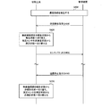
- FIG. 10 is a diagram showing an example of a sequence of communication processing in the tool system according to the embodiment of the present disclosure.
- FIG. 10 shows a sequence of communication processing in the above-described specific example 1 of switching processing.
- step S402 the management device 200 and the cutting tool 100 establish a communication connection.
- the management device 200 transmits a transmission start instruction to the cutting tool 100 (step S404).
- the cutting tool 100 switches the wireless communication unit 30 from the non-reporting state to the reporting state, and switches the measurement sensor 10 from the non-measuring state to the measuring state (step S406).
- the cutting tool 100 wirelessly transmits the sensor packet including the measurement information to the management device 200 periodically or irregularly (step S408).
- the management device 200 transmits a transmission stop instruction to the cutting tool 100 (step S410).
- the cutting tool 100 switches the wireless communication unit 30 from the reporting state to the non-reporting state, and switches the measurement sensor 10 from the measuring state to the non-measuring state (step S412).
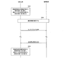
- FIG. 11 is a diagram showing an example of a sequence of communication processing in the tool system according to the embodiment of the present disclosure.
- FIG. 11 shows a sequence of communication processing in the above-mentioned specific example 2 of the switching processing.
- the cutting tool 100 switches the wireless communication unit 30 from the non-reporting state to the reporting state, and switches the measurement sensor 10 from the non-measurement state. Switch to the measurement state (step S502).
- step S504 the management device 200 and the cutting tool 100 establish a communication connection.
- the cutting tool 100 wirelessly transmits the sensor packet including the measurement information to the management device 200 periodically or irregularly (step S506).
- the management device 200 transmits a transmission stop instruction to the cutting tool 100 (step S508).
- the cutting tool 100 switches the wireless communication unit 30 from the reporting state to the non-reporting state, and switches the measurement sensor 10 from the non-measuring state to the measuring state (step S510).
- the management device 200 transmits an advertisement packet to the cutting tool 100 via the wireless master unit 201, and the cutting tool 100 sends a response packet via the wireless master unit 201 to the management device.
- the configuration is to transmit to 200
- the present invention is not limited to this.
- the cutting tool 100 may transmit the advertisement packet to the management device 200 via the wireless master unit 201, and the management device 200 may transmit the response packet to the cutting tool 100 via the wireless master unit 201.
- control unit 40 in the sensor module 110 sets a broadcast address as the destination in the MAC header, sets the MAC address of its own sensor module 110 as the source in the MAC header, and sets the fields corresponding to the message type.
- An advertisement packet in which an identifier indicating that the packet is an advertisement packet is set is generated, and the generated advertisement packet is output to the wireless communication unit 30.
- the wireless communication unit 30 in the sensor module 110 transmits a wireless signal including an advertisement packet received from the control unit 40 in the activated state.
- the management device 200 When the management device 200 receives the advertisement packet from the sensor module 110 via the wireless master unit 201, the management device 200 sets the sensor module 110 having the MAC address of the source included in the received advertisement packet as the communication target.
- the management device 200 generates a response packet that is a response to the received advertisement packet, and transmits the generated response packet to the wireless master unit 201.
- the management device 200 sets the MAC address of the sensor module 110 as the destination in the MAC header, sets its own MAC address as the source in the MAC header, and indicates that it is a response packet in the field corresponding to the message type.
- a response packet with an identifier set is generated, and the generated response packet is transmitted to the wireless master unit 201.
- the wireless master unit 201 transmits a wireless signal including a response packet received from the management device 200.
- the wireless communication unit 30 in the sensor module 110 receives the response packet from the management device 200 via the wireless master unit 201 in the activated state, the wireless communication unit 30 outputs the received response packet to the control unit 40.
- control unit 40 in the sensor module 110 receives the response packet from the wireless communication unit 30, the control unit 40 sets the management device 200 having the MAC address of the source included in the received advertisement packet as the communication target.
- the wireless communication unit 30 has a configuration in which the reporting state and the non-reporting state are switched, but the present invention is not limited to this.
- the wireless communication unit 30 may always be in the reporting state without switching to the non-reporting state.
- the measurement sensor 10 has a configuration in which the measurement state and the non-measurement state are switched, but the present invention is not limited to this.
- the measurement sensor 10 may always be in the measurement state without switching to the non-measurement state.
- control unit 40 switches between the reported state and the non-reported state of the wireless communication unit 30 and the measured state and the non-measured state of the measurement sensor 10 as a switching process.
- the control unit 40 may be configured to switch between the reported state and the non-reported state of the wireless communication unit 30 and the measured state and the non-measured state of the measurement sensor 10 as the switching process.
- the control unit 40 is configured to perform a switching process of switching the measurement sensor 10 between the measurement state and the non-measurement state, but the present invention is not limited to this. Absent.
- the control unit 40 sets the data generation unit 20 into a generation state in which measurement information is generated and a non-generation state in which measurement information is not generated. It may be configured to switch to. Specifically, for example, when the measurement sensor 10 is a thermocouple, the control unit 40 switches the data generation unit 20 between the generated state and the non-generated state instead of the switching process of the measurement sensor 10.
- the measurement sensor 10 is configured to output an analog signal indicating the measured physical quantity to the data generation unit 20, but the present invention is not limited to this.
- the measurement sensor 10 may be configured to AD-convert the analog signal to generate a digital signal and output the generated digital signal to the data generation unit 20.
- the cutting tool 100 is configured to include a start sensor 50, but the present invention is not limited to this.
- the cutting tool 100 may not be provided with the start sensor 50, for example, in the above-described specific example 1 of the switching process.
- control unit 40 is configured to intermittently drive the start sensor 50, but the present invention is not limited to this.
- the control unit 40 may be configured to continuously drive the activation sensor 50.
- the wireless communication unit 30 is configured to wirelessly transmit measurement information to the management device 200, but the present invention is not limited to this.
- the wireless communication unit 30 may be configured to wirelessly transmit measurement information to a device other than the management device 200.
- a technique is desired in which a sensor is mounted on a cutting tool 100 and the life of a tool such as a cutting insert can be predicted based on the measurement result by the sensor.
- the cutting tool 100 for milling rotates during machining, so that the measurement result of the sensor is transmitted from the cutting tool 100 to an external device. It is difficult to transmit by wire to.
- the turret rotates in each process to automatically rotate the cutting tool 100 used for machining. It is difficult to transmit the measurement result of the sensor from the cutting tool 100 to the external device by wire in the processing machine replaced with.
- the processing machine needs to be configured to receive the measurement result of the sensor. Therefore, the conventional processing machine can be used for general purposes. It will be difficult.
- the cutting insert 1 has a cutting edge.
- the holder 2 holds the cutting insert 1.
- the battery 60, the measurement sensor 10, and the wireless communication unit 30 are provided in the holder 2.
- the wireless communication unit 30 is driven by the electric power supplied from the battery 60, and wirelessly transmits measurement information including the measurement result of the measurement sensor 10 or information based on the measurement result.
- the cutting tool 100 and an external device such as the management device 200 can be connected by wire by the configuration of wirelessly transmitting the measurement result of the measurement sensor 10 provided in the holder 2 or the measurement information including the information based on the measurement result.
- the measurement information can be transmitted to the external device without connecting the cutting tool 100 and the processing machine by wire.
- the cutting tool 100 can realize an excellent function for predicting the life of the cutting tool.
- control unit 40 is provided in the holder 2.
- the control unit 40 can switch the wireless communication unit 30 between a reporting state in which the measurement information is wirelessly transmitted and a non-reporting state in which the measurement information is not wirelessly transmitted.
- the configuration that can switch between the reporting state and the non-reporting state of the wireless communication unit 30 suppresses the consumption of power required for wirelessly transmitting the measurement information, and reduces the frequency of battery replacement or charging. At the same time, it is possible to suppress an increase in wireless traffic.
- control unit 40 is provided in the holder 2.
- the control unit 40 can switch the measurement sensor 10 between a measurement state and a non-measurement state.
- the configuration capable of switching between the measurement state and the non-measurement state of the measurement sensor 10 can suppress the power consumption by the measurement sensor 10 and reduce the frequency of battery replacement or charging.
- control unit 40 can switch the measurement sensor 10 between the measurement state and the non-measurement state.
- the configuration capable of switching between the measurement state and the non-measurement state of the measurement sensor 10 can suppress the power consumption by the measurement sensor 10 and reduce the frequency of battery replacement or charging.
- the wireless communication unit 30 periodically transitions to a state in which an instruction from the outside of the cutting tool 100 can be received in a non-reporting state.
- the control unit 40 switches the wireless communication unit 30 from the non-reporting state to the reporting state, and switches the measurement sensor 10 from the non-measurement state to the measurement state.
- the wireless communication unit 30 can be switched from the non-reporting state to the reporting state and the measurement sensor 10 can be switched from the non-measuring state to the measuring state by using an instruction from an external device such as the management device 200 as a trigger. it can. Further, in the non-reporting state, the wireless communication unit 30 periodically transitions to a state in which the instruction can be received, so that the wireless communication unit 30 receives the instruction regarding switching of the states of the wireless communication unit 30 and the measurement sensor 10 from the outside. The power consumption required for wireless communication can be reduced.
- the start sensor 50 is provided in the holder 2.
- the control unit 40 switches the wireless communication unit 30 from the non-reporting state to the reporting state, and switches the measurement sensor 10 from the non-measurement state to the measurement state.
- the states of the wireless communication unit 30 and the measurement sensor 10 can be switched using the measurement result of the activation sensor 50 as a trigger. Therefore, the trigger for switching the states of the wireless communication unit 30 and the measurement sensor 10 is cut. Reception from the outside of the tool 100 becomes unnecessary.
- the activation sensor 50 for example, a sensor having a smaller current consumption than the measurement sensor 10 is used, or the activation sensor 50 is intermittently driven to acquire the timing for switching the states of the wireless communication unit 30 and the measurement sensor 10. Therefore, the power consumption required for this can be reduced.
- the control unit 40 stops the start sensor 50 when the measurement result of the start sensor 50 satisfies the first condition. After the wireless communication unit 30 wirelessly transmits the measurement information, the control unit 40 switches the wireless communication unit 30 from the reporting state to the non-reporting state, and switches the measurement sensor 10 from the measuring state to the non-measuring state.
- the wireless communication unit 30 can be switched to the non-reporting state and the measurement sensor 10 can be switched to the non-measuring state while reducing the power consumption of the activation sensor 50.
- the control unit 40 switches the wireless communication unit 30 from the reporting state to the non-reporting state, and switches the measurement sensor 10. Switch from the measured state to the non-measured state.
- the wireless communication unit 30 can be switched from the reporting state to the non-reporting state and the measurement sensor 10 can be switched from the measuring state to the non-measuring state by using an instruction from an external device such as the management device 200 as a trigger. it can.
- control unit 40 switches the wireless communication unit 30 from the reporting state to the non-reporting state when the measurement result of the activation sensor 50 satisfies the second condition.
- the measurement sensor 10 is switched from the measurement state to the non-measurement state.
- the wireless communication unit 30 can be switched from the reporting state to the non-reporting state by using the measurement result of the activation sensor 50 as a trigger, and the measurement sensor 10 can be switched from the measuring state to the non-measuring state. It is not necessary to receive the trigger related to the switching of the states of the 30 and the measurement sensor 10 from the outside of the cutting tool 100.
- the cutting tool 100 includes a cutting insert 1 having a cutting edge, a holder 2 for holding the cutting insert 1, and a battery and a measuring sensor 10 provided on the holder 2. And the wireless communication unit.
- the cutting tool 100 wirelessly transmits the measurement information including the measurement result of the measurement sensor 10 or the information based on the measurement result to the management device 200.
- the cutting tool 100 and the management device 200 are configured to wirelessly transmit the measurement result of the measurement sensor 10 provided in the holder 2 or the measurement information including the information based on the measurement result to the management device 200.
- the measurement information can be transmitted to the management device 200 without connecting the cutting tool 100 and the processing machine by wire.
- the tool system 300 can realize an excellent function regarding the prediction of the life of the cutting tool.
- the management device 200 transmits a transmission start instruction indicating that the transmission of measurement information should be started to the cutting tool 100. Upon receiving the transmission start instruction, the cutting tool 100 starts wireless transmission of the measurement information.
- the cutting tool 100 can start wireless transmission of measurement information by using the transmission start instruction received from the management device 200 as a trigger. Therefore, the cutting tool 100 itself triggers the transmission start instruction. No configuration is required for detection.
- the cutting tool 100 includes a start sensor 50 provided in the holder 2 and a control unit 40 provided in the holder 2.
- the control unit 40 can switch the measurement sensor 10 between the measurement state and the non-measurement state, and the wireless communication unit 30 wirelessly transmits the measurement information to the management device 200 and the non-report state in which the measurement information is not transmitted wirelessly. It is possible to switch to the state.
- the control unit 40 switches the wireless communication unit 30 from the non-reporting state to the reporting state, and switches the measurement sensor 10 from the non-measurement state to the measurement state.
- the wireless communication unit 30 in order to wirelessly transmit the measurement information by the configuration in which the reporting state and the non-reporting state of the wireless communication unit 30 can be switched and the measuring state and the non-measuring state of the measuring sensor 10 can be switched. It is possible to reduce the consumption of required power, reduce the frequency of battery replacement or charging, and suppress the increase in wireless traffic. Further, since the states of the wireless communication unit 30 and the measurement sensor 10 can be switched by using the measurement result of the activation sensor 50 as a trigger, the outside of the cutting tool 100 of the trigger related to the switching of the states of the wireless communication unit 30 and the measurement sensor 10. No need to receive from.
- the activation sensor 50 for example, a sensor having a smaller current consumption than the measurement sensor 10 is used, or the activation sensor 50 is intermittently driven to acquire the timing for switching the states of the wireless communication unit 30 and the measurement sensor 10. Therefore, the power consumption required for this can be reduced.
- the control unit 40 stops the start sensor 50 when the measurement result of the start sensor 50 satisfies the first condition. After the wireless communication unit 30 transmits the measurement information to the management device 200, the control unit 40 switches the wireless communication unit 30 from the reporting state to the non-reporting state, and switches the measurement sensor 10 from the measuring state to the non-measuring state.
- the wireless communication unit 30 can be switched to the non-reporting state and the measurement sensor 10 can be switched to the non-measuring state while reducing the power consumption of the activation sensor 50.
- control unit 40 switches the wireless communication unit 30 from the reporting state to the non-reporting state when the wireless communication unit 30 receives an instruction from the management device 200.
- the measurement sensor 10 is switched from the measurement state to the non-measurement state.
- the wireless communication unit 30 can be switched from the reporting state to the non-reporting state and the measurement sensor 10 can be switched from the measuring state to the non-measuring state by using the instruction from the management device 200 as a trigger.
- control unit 40 switches the wireless communication unit 30 from the reporting state to the non-reporting state when the measurement result of the activation sensor 50 satisfies the second condition.
- the measurement sensor 10 is switched from the measurement state to the non-measurement state.
- the wireless communication unit 30 can be switched from the reporting state to the non-reporting state and the measurement sensor 10 can be switched from the measuring state to the non-measuring state by using the measurement result of the activation sensor 50 as a trigger. It is not necessary to receive the trigger related to the switching of the states of the unit 30 and the measurement sensor 10 from the outside of the cutting tool 100.
- the communication method includes a cutting insert 1 having a cutting edge, a holder 2 for holding the cutting insert 1, and a battery, a measurement sensor 10, and a wireless communication unit provided in the holder 2.
- the management device 200 and the cutting tool 100 establish a communication connection.
- the cutting tool 100 wirelessly transmits the measurement information including the measurement result of the measurement sensor 10 or the information based on the measurement result to the management device 200.
- the cutting tool 100 and the management device 200 are subjected to a method in which the cutting tool 100 wirelessly transmits the measurement result of the measurement sensor 10 provided in the holder 2 or the measurement information including the information based on the measurement result to the management device 200.
- the measurement information can be transmitted to the management device 200 without connecting the cutting tool 100 and the processing machine by wire.
- the communication method according to the embodiment of the present disclosure can realize an excellent function related to the prediction of the life of the cutting tool.
- the cutting insert 1 has a cutting edge.
- the holder 2 holds the cutting insert 1.
- the battery 60, the measurement sensor 10, the activation sensor 50, the storage unit 70, and the wireless communication unit 30 are provided in the holder 2.
- the battery 60 supplies electric power to the measurement sensor 10, the activation sensor 50, the storage unit 70, and the wireless communication unit 30.
- the measurement sensor 10 includes at least one of an acceleration sensor and a strain sensor.
- the activation sensor 50 includes at least one of a proximity sensor, a distance sensor, an ultrasonic sensor, a photoelectric sensor, a laser sensor, a temperature sensor, and an illuminance sensor.
- the wireless communication unit 30 wirelessly transmits measurement information including the measurement result of the measurement sensor 10 or information based on the measurement result.
- the turning tool and the external device such as the management device 200 can be connected by wire.
- the measurement information can be transmitted to the external device without connecting the turning tool and the processing machine by wire.
- the turning tool according to the embodiment of the present disclosure can realize an excellent function for predicting the life of the cutting tool.
- the control unit 40 is provided in the holder 2.
- the control unit 40 can switch the measurement sensor 10 between the measurement state and the non-measurement state, and switches the wireless communication unit 30 between the reporting state in which the measurement information is wirelessly transmitted and the non-reporting state in which the measurement information is not wirelessly transmitted. It is possible.
- the control unit 40 switches the wireless communication unit 30 from the non-reporting state to the reporting state, and switches the measurement sensor 10 from the non-measurement state to the measurement state. Switch to.
- the activation sensor 50 for example, a sensor having a smaller current consumption than the measurement sensor 10 is used, or the activation sensor 50 is intermittently driven to acquire the timing for switching the states of the wireless communication unit 30 and the measurement sensor 10. Therefore, the power consumption required for this can be reduced.
- the fixing members 3A, 3B, and 3C hold the cutting insert 1.
- the wireless communication unit 30 is driven by the electric power supplied from the battery 60, and wirelessly transmits measurement information including the measurement result of the measurement sensor 10 or information based on the measurement result.
- the cutting tool 100 and an external device such as the management device 200 can be connected by wire by the configuration of wirelessly transmitting the measurement result of the measurement sensor 10 provided in the holder 2 or the measurement information including the information based on the measurement result.
- the measurement information can be transmitted to the external device without connecting the cutting tool 100 and the processing machine by wire.
- the holder 2 according to the embodiment of the present disclosure can realize an excellent function regarding the prediction of the life of the cutting tool.
- control unit 40 can switch the wireless communication unit 30 between a reporting state in which the measurement information is wirelessly transmitted and a non-reporting state in which the measurement information is not wirelessly transmitted. ..
- the configuration that can switch between the reporting state and the non-reporting state of the wireless communication unit 30 suppresses the consumption of power required for wirelessly transmitting the measurement information, and reduces the frequency of battery replacement or charging. At the same time, it is possible to suppress an increase in wireless traffic.
- control unit 40 can switch the measurement sensor 10 between the measurement state and the non-measurement state.
- the configuration capable of switching between the measurement state and the non-measurement state of the measurement sensor 10 can suppress the power consumption by the measurement sensor 10 and reduce the frequency of battery replacement or charging.
- [Appendix 1] It ’s a cutting tool, A holder that holds an insert with a cutting edge, It is provided with a battery, a measurement sensor, and a wireless communication unit provided in the holder.
- the wireless communication unit is driven by the electric power supplied from the battery, and wirelessly transmits measurement information including the measurement result of the measurement sensor or information based on the measurement result to a management device outside the cutting tool.
- the cutting tool is a tool for turning and
- the measuring sensor is a cutting tool provided in the vicinity of the insert in the holder.
- Appendix 2 A holder that holds an insert with a cutting edge, and a cutting tool that includes a measuring sensor provided in the holder. Equipped with a management device The cutting tool wirelessly transmits measurement information including the measurement result of the measurement sensor or information based on the measurement result to the management device.
- the cutting tool is a tool for turning and
- the measuring sensor is a tool system provided in the vicinity of the insert in the holder.
Landscapes
- Engineering & Computer Science (AREA)
- Mechanical Engineering (AREA)
- Machine Tool Sensing Apparatuses (AREA)
- Cutting Tools, Boring Holders, And Turrets (AREA)
- Arrangements For Transmission Of Measured Signals (AREA)
Abstract
切削工具は、切刃を有する切削インサートと、前記切削インサートを保持するホルダと、前記ホルダに設けられた、電池、測定センサおよび無線通信部とを備える切削工具であって、前記無線通信部は、前記電池から供給される電力により駆動され、前記測定センサの測定結果または前記測定結果に基づく情報、を含む測定情報を無線送信する。
Description
本開示は、切削工具、切削工具用ホルダ、工具システム、通信方法および旋削用工具に関する。
この出願は、2019年8月9日に出願された日本出願特願2019-147395号を基礎とする優先権を主張し、その開示のすべてをここに取り込む。
この出願は、2019年8月9日に出願された日本出願特願2019-147395号を基礎とする優先権を主張し、その開示のすべてをここに取り込む。
特許文献1(特開2014-46407号公報)には、以下のような切削工具が開示されている。すなわち、切削工具は、逃げ面とすくい面とを繋ぐ領域で刃先処理が施されてなる刃先処理部と、前記刃先処理部と前記逃げ面との境界に形成される切刃稜線とを具える切削工具であって、前記切削工具を前記すくい面側から平面視した際、前記刃先処理部とすくい面との境界と前記切刃稜線とを結んだ最短距離を前記刃先処理部の幅とするとき、前記刃先処理部において、前記刃先処理部とすくい面との境界から前記刃先処理部の幅の90%までの領域に、切削に関与する前記切刃稜線に沿った溝を具える。
本開示の切削工具は、切刃を有する切削インサートと、前記切削インサートを保持するホルダと、前記ホルダに設けられた、電池、測定センサおよび無線通信部とを備える切削工具であって、前記無線通信部は、前記電池から供給される電力により駆動され、前記測定センサの測定結果または前記測定結果に基づく情報、を含む測定情報を無線送信する。
本開示の工具システムは、切刃を有する切削インサート、前記切削インサートを保持するホルダ、ならびに前記ホルダに設けられた、電池、測定センサおよび無線通信部を含む切削工具と、管理装置とを備え、前記切削工具は、前記測定センサの測定結果または前記測定結果に基づく情報、を含む測定情報を前記管理装置へ無線送信する。
本開示の通信方法は、切刃を有する切削インサート、前記切削インサートを保持するホルダ、ならびに前記ホルダに設けられた、電池、測定センサおよび無線通信部を含む切削工具と、管理装置とを備える工具システムにおける通信方法であって、前記管理装置および前記切削工具が、通信接続を確立するステップと、前記切削工具が、前記測定センサの測定結果または前記測定結果に基づく情報、を含む測定情報を前記管理装置へ無線送信するステップとを含む。
本開示の旋削用工具は、切刃を有する切削インサートと、前記切削インサートを保持するホルダと、前記ホルダに設けられた、電池、測定センサ、起動センサ、メモリおよび無線通信部とを備える旋削用工具であって、前記電池は、前記測定センサ、前記起動センサ、前記メモリおよび前記無線通信部に電力を供給し、前記測定センサは、加速度センサまたは歪みセンサを含み、前記起動センサは、近接センサ、距離センサ、超音波センサ、光電センサ、レーザセンサ、温度センサおよび照度センサのうちの少なくとも1つであり、前記無線通信部は、前記測定センサの測定結果または前記測定結果に基づく情報、を含む測定情報を無線送信する。
本開示の切削工具用ホルダは、切削インサートを保持する保持部と、電池、測定センサおよび無線通信部とを備え、前記無線通信部は、前記電池から供給される電力により駆動され、前記測定センサの測定結果または前記測定結果に基づく情報、を含む測定情報を無線送信する。
本開示の一態様は、切削工具の一部または全部を実現する半導体集積回路として実現され得る。また、本開示の一態様は、旋削用工具の一部または全部を実現する半導体集積回路として実現され得る。また、本開示の一態様は、工具システムの一部または全部を実現する半導体集積回路として実現され得る。また、本開示の一態様は、通信方法における処理のステップをコンピュータに実行させるためのプログラムとして実現され得る。また、本開示の一態様は、切削工具用ホルダの一部または全部を実現する半導体集積回路として実現され得る。
従来、工具寿命に優れる切削工具が開発されている。
[本開示が解決しようとする課題]
切削工具の寿命を予測することにより、切削インサート等の工具を適切なタイミングで交換することができる。このような予測に関する優れた機能を実現することが可能な技術が望まれる。
切削工具の寿命を予測することにより、切削インサート等の工具を適切なタイミングで交換することができる。このような予測に関する優れた機能を実現することが可能な技術が望まれる。
本開示は、上述の課題を解決するためになされたもので、その目的は、切削工具の寿命の予測に関する優れた機能を実現することが可能な切削工具、切削工具用ホルダ、工具システム、通信方法および旋削用工具を提供することである。
[本開示の効果]
本開示によれば、切削工具の寿命の予測に関する優れた機能を実現することができる。
本開示によれば、切削工具の寿命の予測に関する優れた機能を実現することができる。
[本開示の実施形態の説明]
最初に、本開示の実施形態の内容を列記して説明する。
最初に、本開示の実施形態の内容を列記して説明する。
(1)本開示の実施の形態に係る切削工具は、切刃を有する切削インサートと、前記切削インサートを保持するホルダと、前記ホルダに設けられた、電池、測定センサおよび無線通信部とを備える切削工具であって、前記無線通信部は、前記電池から供給される電力により駆動され、前記測定センサの測定結果または前記測定結果に基づく情報、を含む測定情報を無線送信する。
このように、ホルダに設けられた測定センサの測定結果または測定結果に基づく情報を含む測定情報を無線送信する構成により、切削工具と管理装置等の外部装置とを有線接続したり、切削工具と加工機とを有線接続したりすることなく、測定情報を当該外部装置へ伝送することができる。したがって、切削工具の寿命の予測に関する優れた機能を実現することができる。
(2)好ましくは、前記切削工具は、さらに、前記ホルダに設けられた制御部を備え、前記制御部は、前記無線通信部を、前記測定情報を無線送信する報告状態と、前記測定情報を無線送信しない非報告状態とに切り替え可能である。
たとえば、加工時の切削工具の状態を精度良くモニタリングし、センサの測定結果をリアルタイムで解析したり、解析結果に基づいて加工機を制御したりするために、センサによる測定および測定結果の伝送を高頻度で行う必要がある。その一方で、加工機において複数種類の加工を長時間に亘って連続的に行う場合、加工の途中で加工機を停止して切削工具の電池交換または充電を行うことは困難であるところ、このように、無線通信部の報告状態と非報告状態とを切り替え可能である構成により、測定情報を無線送信するために必要な電力の消費を抑え、電池交換または充電を行う頻度を低減することができるとともに、無線トラフィックの増大を抑制することができる。
(3)より好ましくは、前記切削工具は、さらに、前記ホルダに設けられた制御部を備え、前記制御部は、前記測定センサを測定状態と非測定状態とに切り替え可能である。
このように、測定センサの測定状態と非測定状態とを切り替え可能である構成により、測定センサによる電力の消費を抑え、電池交換または充電を行う頻度を低減することができる。
(4)より好ましくは、前記制御部は、前記測定センサを測定状態と非測定状態とに切り替え可能である。
このように、測定センサの測定状態と非測定状態とを切り替え可能である構成により、測定センサによる電力の消費を抑え、電池交換または充電を行う頻度を低減することができる。
(5)より好ましくは、前記無線通信部は、前記非報告状態において、前記切削工具の外部からの指示を受信可能な状態へ周期的に遷移し、前記制御部は、前記無線通信部が前記指示を受信すると、前記無線通信部を前記非報告状態から前記報告状態へ切り替えるとともに、前記測定センサを前記非測定状態から前記測定状態へ切り替える。
このような構成により、たとえば管理装置等の外部装置からの指示をトリガとして、無線通信部を非報告状態から報告状態へ切り替えるとともに、測定センサを非測定状態から測定状態へ切り替えることができる。また、無線通信部は、非報告状態において、当該指示を受信可能な状態へ周期的に遷移する構成により、無線通信部および測定センサの状態の切り替えに関する当該指示を外部から受信するために必要な電力の消費を抑えることができる。
(6)より好ましくは、前記切削工具は、さらに、前記ホルダに設けられた起動センサを備え、前記制御部は、前記起動センサの測定結果が第1の条件を満たすと、前記無線通信部を前記非報告状態から前記報告状態へ切り替えるとともに、前記測定センサを前記非測定状態から前記測定状態へ切り替える。
このような構成により、起動センサの測定結果をトリガとして無線通信部および測定センサの状態を切り替えることができるため、無線通信部および測定センサの状態の切り替えに係るトリガの、切削工具の外部からの受信が不要となる。また、起動センサとして、たとえば測定センサよりも消費電流の小さいセンサを用いたり、起動センサを間欠駆動したりすることにより、無線通信部および測定センサの状態を切り替えるタイミングを取得するために必要な電力の消費を抑えることができる。
(7)より好ましくは、前記制御部は、前記起動センサの前記測定結果が前記第1の条件を満たすと、前記起動センサを停止させ、前記制御部は、前記無線通信部が前記測定情報を無線送信した後に、前記無線通信部を前記報告状態から前記非報告状態へ切り替えるとともに、前記測定センサを前記測定状態から前記非測定状態へ切り替える。
このような構成により、起動センサの消費電力を低減しつつ、無線通信部を非報告状態へ切り替えるとともに、測定センサを非測定状態へ切り替えることができる。
(8)より好ましくは、前記制御部は、前記無線通信部が前記指示を受信すると、前記無線通信部を前記報告状態から前記非報告状態へ切り替えるとともに、前記測定センサを前記測定状態から前記非測定状態へ切り替える。
このような構成により、たとえば管理装置等の外部装置からの指示をトリガとして、無線通信部を報告状態から非報告状態へ切り替えるとともに、測定センサを測定状態から非測定状態へ切り替えることができる。
(9)より好ましくは、前記制御部は、前記起動センサの前記測定結果が第2の条件を満たすと、前記無線通信部を前記報告状態から前記非報告状態へ切り替えるとともに、前記測定センサを前記測定状態から前記非測定状態へ切り替える。
このような構成により、起動センサの測定結果をトリガとして、無線通信部を報告状態から非報告状態へ切り替えるとともに、測定センサを測定状態から非測定状態へ切り替えることができるため、無線通信部および測定センサの状態の切り替えに係るトリガの、切削工具の外部からの受信が不要となる。
(10)本開示の実施の形態に係る工具システムは、切刃を有する切削インサート、前記切削インサートを保持するホルダ、ならびに前記ホルダに設けられた、電池、測定センサおよび無線通信部を含む切削工具と、管理装置とを備え、前記切削工具は、前記測定センサの測定結果または前記測定結果に基づく情報、を含む測定情報を前記管理装置へ無線送信する。
このように、切削工具が、ホルダに設けられた測定センサの測定結果または測定結果に基づく情報を含む測定情報を、管理装置へ無線送信する構成により、切削工具と管理装置とを有線接続したり、切削工具と加工機とを有線接続したりすることなく、測定情報を管理装置へ伝送することができる。したがって、切削工具の寿命の予測に関する優れた機能を実現することができる。
(11)好ましくは、前記管理装置は、前記測定情報の送信を開始すべき旨を示す送信開始指示を前記切削工具へ送信し、前記切削工具は、前記送信開始指示を受信すると、前記測定情報の無線送信を開始する。
このような構成により、切削工具は、管理装置から受信する送信開始指示をトリガとして測定情報の無線送信を開始することができるため、切削工具において、送信開始指示を開始するトリガを自ら検知するための構成が不要となる。
(12)好ましくは、前記切削工具は、さらに、前記ホルダに設けられた起動センサと、前記ホルダに設けられた制御部とを含み、前記制御部は、前記測定センサを測定状態と非測定状態とに切り替え可能であり、前記無線通信部を、前記測定情報を前記管理装置へ無線送信する報告状態と、前記測定情報を無線送信しない非報告状態とに切り替え可能であり、前記制御部は、前記起動センサの測定結果が第1の条件を満たすと、前記無線通信部を前記非報告状態から前記報告状態へ切り替えるとともに、前記測定センサを前記非測定状態から前記測定状態へ切り替える。
このように、無線通信部の報告状態と非報告状態とを切り替え可能であり、かつ測定センサの測定状態と非測定状態とを切り替え可能である構成により、測定情報を無線送信するために必要な電力の消費を抑え、電池交換または充電を行う頻度を低減することができるとともに、無線トラフィックの増大を抑制することができる。また、起動センサの測定結果をトリガとして無線通信部および測定センサの状態を切り替えることができるため、無線通信部および測定センサの状態の切り替えに係るトリガの、切削工具の外部からの受信が不要となる。さらに、起動センサとして、たとえば測定センサよりも消費電流の小さいセンサを用いたり、起動センサを間欠駆動したりすることにより、無線通信部および測定センサの状態を切り替えるタイミングを取得するために必要な電力の消費を抑えることができる。
(13)より好ましくは、前記制御部は、前記起動センサの測定結果が第1の条件を満たすと、前記起動センサを停止させ、前記制御部は、前記無線通信部が前記測定情報を前記管理装置へ送信した後に、前記無線通信部を前記報告状態から前記非報告状態へ切り替えるとともに、前記測定センサを前記測定状態から前記非測定状態へ切り替える。
このような構成により、起動センサの消費電力を低減しつつ、無線通信部を非報告状態へ切り替えるとともに、測定センサを非測定状態へ切り替えることができる。
(14)より好ましくは、前記制御部は、前記無線通信部が前記管理装置からの指示を受信すると、前記無線通信部を前記報告状態から前記非報告状態へ切り替えるとともに、前記測定センサを前記測定状態から前記非測定状態へ切り替える。
このような構成により、管理装置からの指示をトリガとして、無線通信部を報告状態から非報告状態へ切り替えるとともに、測定センサを測定状態から非測定状態へ切り替えることができる。
(15)より好ましくは、前記制御部は、前記起動センサの前記測定結果が第2の条件を満たすと、前記無線通信部を前記報告状態から前記非報告状態へ切り替えるとともに、前記測定センサを前記測定状態から前記非測定状態へ切り替える。
このような構成により、起動センサの測定結果をトリガとして、無線通信部を報告状態から非報告状態へ切り替えるとともに、測定センサを測定状態から非測定状態へ切り替えることができるため、無線通信部および測定センサの状態の切り替えに係るトリガの、切削工具の外部からの受信が不要となる。
(16)本開示の実施の形態に係る通信方法は、切刃を有する切削インサート、前記切削インサートを保持するホルダ、ならびに前記ホルダに設けられた、電池、測定センサおよび無線通信部を含む切削工具と、管理装置とを備える工具システムにおける通信方法であって、前記管理装置および前記切削工具が、通信接続を確立するステップと、前記切削工具が、前記測定センサの測定結果または前記測定結果に基づく情報、を含む測定情報を前記管理装置へ無線送信するステップとを含む。
このように、切削工具が、ホルダに設けられた測定センサの測定結果または測定結果に基づく情報を含む測定情報を、管理装置へ無線送信する方法により、切削工具と管理装置とを有線接続したり、切削工具と加工機とを有線接続したりすることなく、測定情報を管理装置へ伝送することができる。したがって、切削工具の寿命の予測に関する優れた機能を実現することができる。
(17)本開示の実施の形態に係る旋削用工具は、切刃を有する切削インサートと、前記切削インサートを保持するホルダと、前記ホルダに設けられた、電池、測定センサ、起動センサ、メモリおよび無線通信部とを備える旋削用工具であって、前記電池は、前記測定センサ、前記起動センサ、前記メモリおよび前記無線通信部に電力を供給し、前記測定センサは、加速度センサおよび歪みセンサの少なくともいずれか1つを含み、前記起動センサは、近接センサ、距離センサ、超音波センサ、光電センサ、レーザセンサ、温度センサおよび照度センサのうちの少なくともいずれか1つを含み、前記無線通信部は、前記測定センサの測定結果または前記測定結果に基づく情報、を含む測定情報を無線送信する。
このように、ホルダに設けられた測定センサの測定結果または測定結果に基づく情報を含む測定情報を無線送信する構成により、旋削用工具と管理装置等の外部装置とを有線接続したり、旋削用工具と加工機とを有線接続したりすることなく、測定情報を当該外部装置へ伝送することができる。したがって、切削工具の寿命の予測に関する優れた機能を実現することができる。
(18)好ましくは、前記旋削用工具は、さらに、前記ホルダに設けられた制御部を備え、前記制御部は、前記測定センサを測定状態と非測定状態とに切り替え可能であり、前記無線通信部を、前記測定情報を無線送信する報告状態と、前記測定情報を無線送信しない非報告状態とに切り替え可能であり、前記制御部は、前記起動センサの測定結果が前記メモリに保存された所定条件を満たすと、前記無線通信部を前記非報告状態から前記報告状態へ切り替えるとともに、前記測定センサを前記非測定状態から前記測定状態へ切り替える。
このように、無線通信部の報告状態と非報告状態とを切り替え可能であり、かつ測定センサの測定状態と非測定状態とを切り替え可能である構成により、測定情報を無線送信するために必要な電力の消費を抑え、電池交換または充電を行う頻度を低減することができるとともに、無線トラフィックの増大を抑制することができる。また、起動センサの測定結果をトリガとして無線通信部および測定センサの状態を切り替えることができるため、無線通信部および測定センサの状態の切り替えに係るトリガの、旋削用工具の外部からの受信が不要となる。さらに、起動センサとして、たとえば測定センサよりも消費電流の小さいセンサを用いたり、起動センサを間欠駆動したりすることにより、無線通信部および測定センサの状態を切り替えるタイミングを取得するために必要な電力の消費を抑えることができる。
(19)本開示の実施の形態に係る切削工具用ホルダは、切削インサートを保持する保持部と、電池、測定センサおよび無線通信部とを備え、前記無線通信部は、前記電池から供給される電力により駆動され、前記測定センサの測定結果または前記測定結果に基づく情報、を含む測定情報を無線送信する。
このように、切削工具用ホルダに設けられた測定センサの測定結果または測定結果に基づく情報を含む測定情報を無線送信する構成により、切削工具と管理装置等の外部装置とを有線接続したり、切削工具と加工機とを有線接続したりすることなく、測定情報を当該外部装置へ伝送することができる。したがって、切削工具の寿命の予測に関する優れた機能を実現することができる。
(20)好ましくは、前記切削工具用ホルダは、さらに、制御部を備え、前記制御部は、前記無線通信部を、前記測定情報を無線送信する報告状態と、前記測定情報を無線送信しない非報告状態とに切り替え可能である。
たとえば、加工時の切削工具の状態を精度良くモニタリングし、センサの測定結果をリアルタイムで解析したり、解析結果に基づいて加工機を制御したりするために、センサによる測定および測定結果の伝送を高頻度で行う必要がある。その一方で、加工機において複数種類の加工を長時間に亘って連続的に行う場合、加工の途中で加工機を停止して切削工具の電池交換または充電を行うことは困難であるところ、このように、無線通信部の報告状態と非報告状態とを切り替え可能である構成により、測定情報を無線送信するために必要な電力の消費を抑え、電池交換または充電を行う頻度を低減することができるとともに、無線トラフィックの増大を抑制することができる。
(21)より好ましくは、前記制御部は、前記測定センサを測定状態と非測定状態とに切り替え可能である。
このように、測定センサの測定状態と非測定状態とを切り替え可能である構成により、測定センサによる電力の消費を抑え、電池交換または充電を行う頻度を低減することができる。
以下、本開示の実施の形態について図面を用いて説明する。なお、図中同一または相当部分には同一符号を付してその説明は繰り返さない。また、以下に記載する実施の形態の少なくとも一部を任意に組み合わせてもよい。
[工具システム]
図1は、本開示の実施の形態に係る工具システムの構成を示す図である。
図1は、本開示の実施の形態に係る工具システムの構成を示す図である。
図1を参照して、工具システム300は、切削工具100と、管理装置200と、無線親機201とを備える。切削工具100は、切削工具用ホルダ2と、センサモジュール110とを備える。センサモジュール110は、測定センサを含む。以下、切削工具用ホルダ2を、単にホルダ2とも称する。
無線親機201は、管理装置200にたとえば有線で接続されている。無線親機201は、たとえばアクセスポイントである。
切削工具100は、たとえば、旋削加工用の工具であり、旋削加工機に取り付けられる。ホルダ2は、切刃を有する切削インサート1を保持する。センサモジュール110は、ホルダ2に設けられている。
ホルダ2は、固定用部材3A,3Bを備える。固定用部材3A,3Bは、切削インサート1を保持する。固定用部材3A,3Bは、保持部の一例である。
切削インサート1は、たとえば、上面視で三角形、正方形、ひし形、および五角形等の多角形状である。切削インサート1は、たとえば、上面の中央において貫通孔が形成され、固定用部材3A,3Bによりホルダ2に固定されている。
なお、工具システム300は、1つの切削工具100を備える構成に限らず、複数の切削工具100を備える構成であってもよい。また、工具システム300は、1つの管理装置200を備える構成に限らず、複数の管理装置200を備える構成であってもよい。
切削工具100は、センサモジュール110における測定センサの測定結果を含む測定情報を無線親機201へ無線送信する。あるいは、切削工具100は、センサモジュール110における測定センサの測定結果に基づく情報を含む測定情報を無線親機201へ無線送信する。
たとえば、切削工具100は、測定情報を含むセンサパケットを無線親機201へ無線送信する。
切削工具100および無線親機201は、たとえば、IEEE 802.15.4に準拠したZigBee(登録商標)、IEEE 802.15.1に準拠したBluetooth(登録商標)およびIEEE802.15.3aに準拠したUWB(Ultra Wide Band)等の通信プロトコルを用いた無線による通信を行う。なお、切削工具100および無線親機201間において、上記以外の通信プロトコルが用いられてもよい。
無線親機201は、切削工具100から受信したセンサパケットを管理装置200へ中継する。
図2は、本開示の実施の形態に係る切削工具が送信するセンサパケットの一例を示す図である。
図2を参照して、切削工具100におけるセンサモジュール110は、測定情報および測定センサのIDであるセンサIDを「センサデータ」のフィールドに格納したセンサパケット401を作成する。
ここで、センサパケット401における「同期ヘッダ」のフィールドには、たとえば所定のプリアンブルが格納される。「MAC(Media Access Control)ヘッダ」のフィールドには、たとえば、センサモジュール110のMACアドレス等が格納される。また、「センサデータ」のフィールドのデータ長は、図2では20オクテットであるが、測定情報に含まれる物理量の種別、および当該物理量の個数等に応じて変更可能である。
無線親機201は、切削工具100から受信した無線信号に含まれるセンサパケットを取得して管理装置200へ送信する。
図3は、本開示の実施の形態に係る切削工具の構成の他の例を示す断面図である。
図3を参照して、切削工具100は、転削加工機に取り付けられる転削加工用の工具であってもよい。より詳細には、転削加工用の切削工具100は、切刃を有する複数の切削インサート1Aを保持するホルダ2Aと、ホルダ2Aに設けられた、測定センサを含むセンサモジュール110とを備える。ホルダ2Aは、固定用部材3Cを備える。固定用部材3Cは、切削インサート1Aを保持する。切削インサート1Aは、たとえば、固定用部材3Cによりホルダ2Aに固定されている。固定用部材3Cは、保持部の一例である。
[管理装置]
図4は、本開示の実施の形態に係る管理装置の構成を示す図である。
図4は、本開示の実施の形態に係る管理装置の構成を示す図である。
図4を参照して、管理装置200は、通信部210と、処理部220と、記憶部230とを備える。記憶部230は、たとえばフラッシュメモリである。
通信部210は、無線親機201経由で切削工具100からセンサパケットを受信すると、受信したセンサパケットから測定情報およびセンサIDを取得し、取得した測定情報およびセンサIDを処理部220へ出力する。
処理部220は、通信部210から測定情報およびセンサIDを受けると、当該測定情報を当該センサIDに対応付けて記憶部230に保存する。
処理部220は、記憶部230における測定情報に基づいて、対応のセンサIDに対応する切削工具100における切削インサート1の寿命を予測する。そして、処理部220は、予測結果に基づいて、切削インサート1の交換をユーザに促すための通知を行う。
[センサモジュール]
図5は、本開示の実施の形態に係るセンサモジュールの構成を示す図である。
図5は、本開示の実施の形態に係るセンサモジュールの構成を示す図である。
図5を参照して、センサモジュール110は、測定センサ10と、データ生成部20と、無線通信部30と、制御部40と、起動センサ50と、電池60と、記憶部70とを含む。記憶部70は、たとえばフラッシュメモリである。無線通信部30は、たとえば無線通信チップにより実現される。
電池60は、たとえば1次電池、2次電池、太陽電池、またはキャパシタ等を含む蓄電装置である。電池60は、エネルギーを蓄積するとともに、蓄積したエネルギーを用いて、センサモジュール110における無線通信部30等の各回路に電力を供給する。
起動センサ50は、たとえば、近接センサ、距離センサ、超音波センサ、光電センサ、レーザセンサ、温度センサおよび照度センサのうちの少なくともいずれか1つを含む。
起動センサ50は、対象物たとえば加工物との間の距離、温度および照度等の物理量のうちの少なくともいずれか1つを測定し、測定した物理量を示すアナログ信号を制御部40へ出力する。起動センサ50は、たとえば、電池60から供給される電力により駆動される。制御部40は、たとえばCPU(Central Processing Unit)等のプロセッサである。
起動センサ50は、たとえば、制御部40により起動され、起動状態において測定を行い、測定した物理量を示すアナログ信号を制御部40へ出力する。
測定センサ10は、たとえば、加速度センサ、歪みセンサ、圧力センサ、音センサおよび温度センサのうちの少なくともいずれか1つを含む。測定センサ10は、たとえば、ホルダ2,2Aにおける切削インサート1の近傍に設けられる。
測定センサ10は、加速度、ひずみ、圧力、音および温度等の物理量のうちの少なくともいずれか1つを測定し、測定した物理量を示すアナログ信号をデータ生成部20へ出力する。測定センサ10は、たとえば、電池60から供給される電力により駆動される。
測定センサ10は、たとえば、測定状態と非測定状態とが切り替わる。測定センサ10は、測定状態において測定を行い、測定した物理量を示すアナログ信号をデータ生成部20へ出力する一方、非測定状態において停止する。
データ生成部20は、測定センサ10の測定結果または測定結果に基づく情報、を含む測定情報を作成する。より詳細には、データ生成部20は、測定センサ10からアナログ信号を受けて、受けたアナログ信号をAD(Analog Digital)変換したセンサ測定値を含む測定情報、または当該センサ測定値に対して平均化等の演算を行った値を含む測定情報を作成する。
データ生成部20は、生成した測定情報および測定センサ10のセンサIDが格納されたセンサパケットを生成し、生成したセンサパケットを無線通信部30へ出力する。
無線通信部30は、切削工具100の外部における無線親機201へ測定情報を無線送信する。より詳細には、無線通信部30は、データ生成部22から受けた、測定情報およびセンサIDが格納されたセンサパケットを無線親機201へ無線送信する。無線通信部30は、電池から供給される電力により駆動される。
たとえば、無線通信部30は、報告状態と非報告状態とが切り替わる。無線通信部30は、報告状態においてセンサパケットを無線親機201へ無線送信する一方、非報告状態においてセンサパケットを無線親機201へ無線送信しない。
制御部40は、無線通信部30、測定センサ10および起動センサ50の動作を制御する。
より詳細には、制御部40は、無線通信部30の報告状態および非報告状態、ならびに測定センサ10の測定状態および非測定状態を切り替える切替処理を行う。また、たとえば、制御部40は、起動センサ50の起動および停止を制御する。
[通信接続]
切削工具100のセンサモジュール110における制御部40は、管理装置200との通信接続を確立する接続処理を行う。
切削工具100のセンサモジュール110における制御部40は、管理装置200との通信接続を確立する接続処理を行う。
たとえば、工具システム300において、管理装置200は、アドバタイズパケットを切削工具100へ送信する。
図6は、本発明の実施の形態に係る工具システムにおける管理装置が送信するアドバタイズパケットのフォーマットの一例を示す図である。
図6を参照して、アドバタイズパケットは、先頭から、PHYヘッダ、MACヘッダおよびメッセージタイプに対応するフィールドの順に構成されている。
管理装置200は、MACヘッダにおける宛先にブロードキャストアドレスを設定し、MACヘッダにおける送信元に自己のIDたとえばMACアドレスを設定し、メッセージタイプに対応するフィールドにアドバタイズパケットであることを示す識別子を設定したアドバタイズパケットを生成し、生成したアドバタイズパケットを無線親機201へ送信する。
無線親機201は、管理装置200から受信したアドバタイズパケットを含む無線信号を切削工具100へ送信する。
センサモジュール110における無線通信部30は、起動状態において、無線親機201から無線信号を受信し、受信した無線信号に含まれるアドバタイズパケットを取得する。無線通信部30は、取得したアドバタイズパケットを制御部40へ出力する。
センサモジュール110における制御部40は、無線通信部30からアドバタイズパケットを受けると、接続処理として、受けたアドバタイズパケットに含まれる送信元のMACアドレスを有する管理装置200を通信対象として設定する。具体的には、制御部40は、当該MACアドレスを、通信対象の管理装置200のMACアドレスとして記憶部70に登録する。
また、制御部40は、接続処理として、受けたアドバタイズパケットに対する応答である応答パケットを生成し、生成した応答パケットを無線通信部30へ出力する。制御部40が生成する応答パケットのフォーマットは、たとえば図6に示すアドバタイズパケットのフォーマットと同じである。
たとえば、制御部40は、MACヘッダにおける宛先に管理装置200のMACアドレスを設定し、MACヘッダにおける送信元にたとえば自己のセンサモジュール110のMACアドレスを設定し、メッセージタイプに対応するフィールドに応答パケットであることを示す識別子を設定した応答パケットを生成し、生成した応答パケットを無線通信部30へ出力する。
無線通信部30は、起動状態において、制御部40から受けた応答パケットを含む無線信号を送信する。
管理装置200は、無線親機201経由で切削工具100のセンサモジュール110からの応答パケットを受信すると、受信した応答パケットに含まれる送信元のMACアドレスを有するセンサモジュール110を通信対象として設定する。具体的には、管理装置200における処理部220は、無線親機201および通信部210経由でセンサモジュール110から応答パケットを受信すると、受信した応答パケットに含まれる送信元のMACアドレスを、通信対象のセンサモジュール110のMACアドレスとして記憶部70に登録する。
[切替処理の具体例1]
たとえば、センサモジュール110における無線通信部30は、非報告状態において、管理装置200からの指示を受信可能な状態へ周期的に遷移する。具体的には、センサモジュール110における制御部40は、無線通信部30の非報告状態において、無線通信部30を間欠駆動する。より詳細には、制御部40は、無線通信部30の停止状態および起動状態を所定の切替周期で切り替えることにより、無線通信部30を間欠的に起動状態とする。以下、停止状態とは、一部の機能が停止した状態すなわちスリープ状態を含む。
たとえば、センサモジュール110における無線通信部30は、非報告状態において、管理装置200からの指示を受信可能な状態へ周期的に遷移する。具体的には、センサモジュール110における制御部40は、無線通信部30の非報告状態において、無線通信部30を間欠駆動する。より詳細には、制御部40は、無線通信部30の停止状態および起動状態を所定の切替周期で切り替えることにより、無線通信部30を間欠的に起動状態とする。以下、停止状態とは、一部の機能が停止した状態すなわちスリープ状態を含む。
管理装置200は、上記切替周期よりも短い周期で、アドバタイズパケットを切削工具100へ送信する。
センサモジュール110における無線通信部30は、間欠駆動における起動状態において、管理装置200からのアドバタイズパケットを受信すると、受信したアドバタイズパケットを制御部40へ出力する。
センサモジュール110における制御部40は、無線通信部30からアドバタイズパケットを受けると、管理装置200との通信接続を確立する接続処理を行うとともに、無線通信部30の連続駆動を開始し、無線通信部30の起動状態を維持する。
たとえば、管理装置200は、測定情報の送信を開始すべき旨を示す送信開始指示を通信対象の切削工具100へ送信する。より詳細には、管理装置200は、送信開始指示を無線親機201へ送信する。
無線親機201は、管理装置200から受信した送信開始指示を含む無線信号を切削工具100へ送信する。
切削工具100は、管理装置200から送信開始指示を受信すると、測定情報の無線送信を開始する。
より詳細には、切削工具100のセンサモジュール110における無線通信部30は、無線親機201経由で管理装置200からの送信開始指示を受信すると、受信した送信開始指示を制御部40へ出力する。
制御部40は、無線通信部30から送信開始指示を受けると、無線通信部30を非報告状態から報告状態へ切り替えるとともに、測定センサ10を非測定状態から測定状態へ切り替える。
具体的には、制御部40は、センサパケットの無線送信を開始すべき旨を示す報告開始指示を無線通信部30へ出力するとともに、測定センサ10を停止状態から起動状態へ切り替える。
測定センサ10は、測定状態すなわち起動状態へ切り替わると、測定を開始するとともに、測定した物理量を示すアナログ信号のデータ生成部20への出力を開始する。
無線通信部30は、制御部40から報告開始指示を受けると、定期的または不定期に、データ生成部20により生成される、測定情報を含むセンサパケットの管理装置200への無線送信を開始する。
たとえば、管理装置200は、測定情報の送信を停止すべき旨を示す送信停止指示を切削工具100へ送信する。より詳細には、管理装置200は、送信停止指示を無線親機201へ送信する。
無線親機201は、管理装置200から受信した送信停止指示を含む無線信号を切削工具100へ送信する。
切削工具100は、管理装置200から送信停止指示を受信すると、センサパケットの無線送信を停止する。
より詳細には、切削工具100のセンサモジュール110における無線通信部30は、無線親機201経由で管理装置200からの送信停止指示を受信すると、受信した送信停止指示を制御部40へ出力する。
制御部40は、無線通信部30から送信停止指示を受けると、無線通信部30を報告状態から非報告状態へ切り替えるとともに、測定センサ10を測定状態から非測定状態へ切り替える。
具体的には、制御部40は、センサパケットの無線送信を停止すべき旨を示す報告停止指示を無線通信部30へ出力するとともに、測定センサ10を起動状態から停止状態へ切り替える。
無線通信部30は、制御部40から報告停止指示を受けると、センサパケットの管理装置200への無線送信を停止する。
制御部40は、無線通信部30を非報告状態へ切り替えると、無線通信部30の間欠駆動を再開し、管理装置200からのアドバタイズパケットを待ち受ける。
[切替処理の具体例2]
たとえば、センサモジュール110における制御部40は、起動センサ50を間欠駆動する。より詳細には、制御部40は、起動センサ50の停止状態および起動状態を所定の切替周期で切り替えることにより、起動センサ50を間欠的に起動状態とする。
たとえば、センサモジュール110における制御部40は、起動センサ50を間欠駆動する。より詳細には、制御部40は、起動センサ50の停止状態および起動状態を所定の切替周期で切り替えることにより、起動センサ50を間欠的に起動状態とする。
たとえば、無線通信部30は、非報告状態において起動センサ50の測定結果が所定条件を満たすと、報告状態へ切り替わる。
たとえば、制御部40は、起動センサの測定結果が第1の条件を満たすと、切替処理を行う。制御部40は、起動センサ50から受けるアナログ信号をモニタし、当該アナログ信号のレベルが、記憶部70に保存されている所定のしきい値ThAを超えると、無線通信部30を非報告状態から報告状態へ切り替えるとともに、測定センサ10を非測定状態から測定状態へ切り替える。
具体的には、制御部40は、起動センサ50の一例としての照度センサ、光電センサまたはレーザセンサの測定結果である、切削工具100を照らす光の明るさが所定のしきい値ThA1を超えると、無線通信部30を報告状態へ切り替えるとともに、測定センサ10を測定状態へ切り替える。すなわち、制御部40は、無線通信部30および測定センサ10を停止状態から起動状態へ切り替える。
あるいは、たとえば、制御部40は、起動センサ50の一例としての距離センサ、近接センサまたは超音波センサの測定結果である、切削工具100および加工物間の距離が所定のしきい値ThA2たとえば10mm以下となると、無線通信部30を報告状態へ切り替えるとともに、測定センサ10を測定状態へ切り替える。すなわち、制御部40は、無線通信部30および測定センサ10を停止状態から起動状態へ切り替える。
あるいは、制御部40は、起動センサ50の一例である光電センサおよびレーザセンサにより、切削工具100が所定の位置に到達したことを検知すると、無線通信部30を報告状態へ切り替えるとともに、測定センサ10を測定状態へ切り替える。すなわち、制御部40は、無線通信部30および測定センサ10を停止状態から起動状態へ切り替える。
あるいは、制御部40は、起動センサ50の一例である超音波センサおよび温度センサにより、たとえばクーラント液により切削工具100の温度が所定値以下となったことを検知すると、無線通信部30を非報告状態から報告状態へ切り替えるとともに、測定センサ10を測定状態へ切り替える。
たとえば、起動センサ50は、起動センサ50の測定結果が所定条件を満たすと、停止する。
より詳細には、制御部40は、起動センサ50から受けるアナログ信号のレベルが上述したしきい値ThAを超えると、起動センサ50の間欠駆動を停止し、起動センサ50の停止状態を維持する。
制御部40は、無線通信部30の報告状態において、無線通信部30経由で管理装置200からのアドバタイズパケットを受信し、当該管理装置200との通信接続を確立する接続処理を行う。
制御部40は、管理装置200との通信接続を確立すると、センサパケットの無線送信を開始すべき旨を示す報告開始指示を無線通信部30へ出力する。
測定センサ10は、測定状態すなわち起動状態へ切り替わると、測定を開始するとともに、測定した物理量を示すアナログ信号のデータ生成部20への出力を開始する。
無線通信部30は、制御部40から報告開始指示を受けると、定期的または不定期に、データ生成部20により生成される、測定情報を含むセンサパケットの管理装置200への無線送信を開始する。
たとえば、無線通信部30は、センサパケットの管理装置200への送信後に非報告状態へ切り替わる。
具体的には、たとえば、管理装置200は、送信停止指示を無線親機201経由で切削工具100へ送信する。
切削工具100は、管理装置200から送信停止指示を受信すると、センサパケットの無線送信を停止する。
切削工具100のセンサモジュール110における制御部40は、無線通信部30が管理装置200から指示を受けると、無線通信部30を報告状態から非報告状態へ切り替えるとともに、測定センサ10を測定状態から非測定状態へ切り替える。より詳細には、制御部40は、無線通信部30経由で管理装置200から送信停止指示を受信すると、無線通信部30を非報告状態へ切り替えるとともに、測定センサ10を非測定状態へ切り替える。
すなわち、制御部40は、無線通信部30および測定センサ10を起動状態から停止状態へ切り替える。
制御部40は、無線通信部30を非報告状態へ切り替え、測定センサ10を非測定状態へ切り替えると、起動センサ50の間欠駆動を再開し、起動センサ50から受けるアナログ信号をモニタする。
[切替処理の具体例3]
たとえば、センサモジュール110における制御部40は、起動センサ50を間欠駆動する。
たとえば、センサモジュール110における制御部40は、起動センサ50を間欠駆動する。
たとえば、無線通信部30は、起動センサ50の測定結果が所定条件を満たすと、起動状態に切り替わる。
より詳細には、制御部40は、起動センサ50から受けるアナログ信号をモニタし、当該アナログ信号のレベルが所定のしきい値ThAを超えると、無線通信部30を非報告状態から報告状態へ切り替えるとともに、測定センサ10を非測定状態から測定状態へ切り替える。
すなわち、制御部40は、無線通信部30および測定センサ10を停止状態から起動状態へ切り替える。
制御部40は、無線通信部30の報告状態において、無線通信部30経由で管理装置200からのアドバタイズパケットを受信し、当該管理装置200との通信接続を確立する接続処理を行う。
制御部40は、管理装置200との通信接続を確立すると、センサパケットの無線送信を開始すべき旨を示す報告開始指示を無線通信部30へ出力する。
測定センサ10は、測定状態すなわち起動状態へ切り替わると、測定を開始するとともに、測定した物理量を示すアナログ信号のデータ生成部20への出力を開始する。
無線通信部30は、制御部40から報告開始指示を受けると、定期的または不定期に、データ生成部20により生成される、測定情報を含むセンサパケットの管理装置200への無線送信を開始する。
たとえば、無線通信部30は、報告状態において起動センサ50の測定結果が、たとえば所定条件である第2の条件を満たすと、非報告状態へ切り替わる。
より詳細には、制御部40は、無線通信部30を非報告状態から報告状態へ切り替えた後において、起動センサ50から受けるアナログ信号をモニタし、当該アナログ信号のレベルが再びしきい値ThAを超えると、無線通信部30を報告状態から非報告状態へ切り替えるとともに、測定センサ10を測定状態から非測定状態へ切り替える。
すなわち、制御部40は、無線通信部30および測定センサ10を起動状態から停止状態へ切り替える。
たとえば、ユーザは、照明器具等を用いて切削工具100を照らすことにより、無線通信部30の報告状態と非報告状態との切り替え、および測定センサ10の測定状態と非測定状態との切り替えを行うことができる。
具体的には、上述のように、制御部40は、起動センサ50の一例としての照度センサの測定結果である、切削工具100を照らす光の明るさがしきい値ThA1を超えると、無線通信部30を報告状態へ切り替えるとともに、測定センサ10を測定状態へ切り替える。
また、制御部40は、無線通信部30を非報告状態から報告状態へ切り替えた後において、照度センサの測定結果をモニタし、切削工具100を照らす光の明るさが再びしきい値ThA1を超えると、無線通信部30を報告状態から非報告状態へ切り替えるとともに、測定センサ10を測定状態から非測定状態へ切り替える。
なお、上記の説明では、制御部40は、同じしきい値ThAを用いて、無線通信部30の非報告状態から報告状態への切り替え、および報告状態から非報告状態への切り替えを行う構成であるとしたが、これに限定するものではない。
また、上記の説明では、制御部40は、同じしきい値ThAを用いて、測定センサ10の非測定状態から測定状態への切り替え、および測定状態から非測定状態への切り替えを行う構成であるとしたが、これに限定するものではない。
たとえば、制御部40は、無線通信部30の非報告状態から報告状態への切り替え、および測定センサ10の非測定状態から測定状態への切り替えを行った後において、起動センサ50から受けるアナログ信号のレベルがしきい値ThAとは異なるしきい値ThBを超えると、無線通信部30を報告状態から非報告状態へ切り替えるとともに、測定センサ10を測定状態から非測定状態へ切り替える。
具体的には、上述のように、制御部40は、起動センサ50の一例としての距離センサの測定結果である、切削工具100および加工物間の距離が所定のしきい値ThA2たとえば10mm以下となると、無線通信部30を報告状態へ切り替えるとともに、測定センサ10を測定状態へ切り替える。
また、制御部40は、無線通信部30の報告状態への切り替え、および測定センサ10の測定状態への切り替えを行った後において、距離センサの測定結果をモニタし、切削工具100および加工物間の距離が所定のしきい値ThB2たとえば20mm以上となると、無線通信部30を報告状態から非報告状態へ切り替えるとともに、測定センサ10を測定状態から非測定状態へ切り替える。
[動作の流れ]
本開示の実施の形態に係る工具システムにおける各装置は、メモリを含むコンピュータを備え、当該コンピュータにおけるCPU等の演算処理部は、以下のフローチャートおよびシーケンスの各ステップの一部または全部を含むプログラムを当該メモリから読み出して実行する。これら複数の装置のプログラムは、それぞれ、外部からインストールすることができる。これら複数の装置のプログラムは、それぞれ、記録媒体に格納された状態で流通する。
本開示の実施の形態に係る工具システムにおける各装置は、メモリを含むコンピュータを備え、当該コンピュータにおけるCPU等の演算処理部は、以下のフローチャートおよびシーケンスの各ステップの一部または全部を含むプログラムを当該メモリから読み出して実行する。これら複数の装置のプログラムは、それぞれ、外部からインストールすることができる。これら複数の装置のプログラムは、それぞれ、記録媒体に格納された状態で流通する。
図7は、本開示の実施の形態に係る工具システムにおいて切削工具が管理装置へセンサパケットを送信する際の動作手順の一例を定めたフローチャートである。図7は、上述した切り替え処理の具体例1における切削工具100の動作手順を示す。
図7を参照して、まず、切削工具100は、無線通信部30の非報告状態において、無線通信部30の間欠駆動を開始する(ステップS102)。
次に、切削工具100は、管理装置200からのアドバタイズパケットを待ち受け(ステップS104でNO)、管理装置200からアドバタイズパケットを受信すると(ステップS104でYES)、無線通信部30の連続駆動を開始する(ステップS106)。
次に、切削工具100は、管理装置200との通信接続を確立する(ステップS108)。
次に、切削工具100は、管理装置200からの送信開始指示を待ち受け(ステップS110でNO)、管理装置200から送信開始指示を受信すると(ステップS110でYES)、無線通信部30を非報告状態から報告状態へ切り替えるとともに、測定センサ10を非測定状態から測定状態へ切り替える(ステップS112)。
次に、切削工具100は、管理装置200へのセンサパケットの無線送信を開始する(ステップS114)。
次に、切削工具100は、管理装置200から送信停止指示を受信するまで管理装置200へのセンサパケットの無線送信を継続し(ステップS116でNO)、管理装置200から送信停止指示を受信すると(ステップS116でYES)、無線通信部30を報告状態から非報告状態へ切り替えるとともに、測定センサ10を測定状態から非測定状態へ切り替える(ステップS118)。
次に、切削工具100は、無線通信部30の間欠駆動を再開し(ステップS102)、管理装置200からのアドバタイズパケットを待ち受ける(ステップS104)。
図8は、本開示の実施の形態に係る工具システムにおいて切削工具が管理装置へセンサパケットを送信する際の動作手順の他の例を定めたフローチャートである。図8は、上述した切り替え処理の具体例2における切削工具100の動作手順を示す。
図8を参照して、まず、切削工具100は、無線通信部30の非報告状態において、起動センサ50の間欠駆動を開始する(ステップS202)。
次に、切削工具100は、起動センサ50の測定結果をモニタし、当該測定結果が所定条件を満たすと(ステップS204でYES)、無線通信部30を非報告状態から報告状態へ切り替えるとともに、測定センサ10を非測定状態から測定状態へ切り替える(ステップS206)。
次に、切削工具100は、起動センサ50を起動状態から停止状態へ切り替え、停止状態を維持する(ステップS208)。
次に、切削工具100は、管理装置200との通信接続を確立する(ステップS210)。
次に、切削工具100は、管理装置200へのセンサパケットの無線送信を開始する(ステップS212)。
次に、切削工具100は、管理装置200から送信停止指示を受信するまで管理装置200へのセンサパケットの無線送信を継続し(ステップS214でNO)、管理装置200から送信停止指示を受信すると(ステップS214でYES)、無線通信部30を報告状態から非報告状態へ切り替えるとともに、測定センサ10を測定状態から非測定状態へ切り替える(ステップS216)。
次に、切削工具100は、起動センサ50の間欠駆動を再開し(ステップS202)、起動センサ50の測定結果をモニタする(ステップS204)。
図9は、本開示の実施の形態に係る工具システムにおいて切削工具が管理装置へセンサパケットを送信する際の動作手順の他の例を定めたフローチャートである。図9は、上述した切り替え処理の具体例3における切削工具100の動作手順を示す。
図9を参照して、まず、切削工具100は、ステップS302からステップS306の処理として、図8におけるステップS202からステップS206と同様の処理を行う。
次に、切削工具100は、管理装置200との通信接続を確立する(ステップS308)。
次に、切削工具100は、管理装置200へのセンサパケットの無線送信を開始する(ステップS310)。
次に、切削工具100は、起動センサ50の測定結果が所定条件を満たすまで管理装置200へのセンサパケットの無線送信を継続し(ステップS312でNO)、起動センサ50の測定結果が所定条件を満たすと(ステップS312でYES)、無線通信部30を報告状態から非報告状態へ切り替えるとともに、測定センサ10を測定状態から非測定状態へ切り替える(ステップS314)。
次に、切削工具100は、起動センサ50の測定結果が所定条件を満たすのを待ち受ける(ステップS304でNO)。
図10は、本開示の実施の形態に係る工具システムにおける通信処理のシーケンスの一例を示す図である。図10は、上述した切り替え処理の具体例1における通信処理のシーケンスを示す。
図10を参照して、まず、管理装置200および切削工具100は、通信接続を確立する(ステップS402)。
次に、管理装置200は、送信開始指示を切削工具100へ送信する(ステップS404)。
次に、切削工具100は、無線通信部30を非報告状態から報告状態へ切り替えるとともに、測定センサ10を非測定状態から測定状態へ切り替える(ステップS406)。
次に、切削工具100は、定期的または不定期に、測定情報を含むセンサパケットを管理装置200へ無線送信する(ステップS408)。
次に、管理装置200は、送信停止指示を切削工具100へ送信する(ステップS410)。
次に、切削工具100は、無線通信部30を報告状態から非報告状態へ切り替えるとともに、測定センサ10を測定状態から非測定状態へ切り替える(ステップS412)。
図11は、本開示の実施の形態に係る工具システムにおける通信処理のシーケンスの一例を示す図である。図11は、上述した切り替え処理の具体例2における通信処理のシーケンスを示す。
図11を参照して、まず、切削工具100は、起動センサ50の測定結果が所定条件を満たすと、無線通信部30を非報告状態から報告状態へ切り替えるとともに、測定センサ10を非測定状態から測定状態へ切り替える(ステップS502)。
次に、管理装置200および切削工具100は、通信接続を確立する(ステップS504)。
次に、切削工具100は、定期的または不定期に、測定情報を含むセンサパケットを管理装置200へ無線送信する(ステップS506)。
次に、管理装置200は、送信停止指示を切削工具100へ送信する(ステップS508)。
次に、切削工具100は、無線通信部30を報告状態から非報告状態へ切り替えるとともに、測定センサ10を非測定状態から測定状態へ切り替える(ステップS510)。
なお、本開示の実施の形態に係る工具システム300では、管理装置200がアドバタイズパケットを無線親機201経由で切削工具100へ送信し、切削工具100が応答パケットを無線親機201経由で管理装置200へ送信する構成であるとしたが、これに限定するものではない。切削工具100がアドバタイズパケットを無線親機201経由で管理装置200へ送信し、管理装置200が応答パケットを無線親機201経由で切削工具100へ送信する構成であってもよい。
より詳細には、センサモジュール110における制御部40は、MACヘッダにおける宛先にブロードキャストアドレスを設定し、MACヘッダにおける送信元に自己のセンサモジュール110のMACアドレスを設定し、メッセージタイプに対応するフィールドにアドバタイズパケットであることを示す識別子を設定したアドバタイズパケットを生成し、生成したアドバタイズパケットを無線通信部30へ出力する。
センサモジュール110における無線通信部30は、起動状態において、制御部40から受けたアドバタイズパケットを含む無線信号を送信する。
管理装置200は、無線親機201経由でセンサモジュール110からのアドバタイズパケットを受信すると、受信したアドバタイズパケットに含まれる送信元のMACアドレスを有するセンサモジュール110を通信対象として設定する。
また、管理装置200は、受けたアドバタイズパケットに対する応答である応答パケットを生成し、生成した応答パケットを無線親機201へ送信する。
たとえば、管理装置200は、MACヘッダにおける宛先にセンサモジュール110のMACアドレスを設定し、MACヘッダにおける送信元に自己のMACアドレスを設定し、メッセージタイプに対応するフィールドに応答パケットであることを示す識別子を設定した応答パケットを生成し、生成した応答パケットを無線親機201へ送信する。
無線親機201は、管理装置200から受信した応答パケットを含む無線信号を送信する。
センサモジュール110における無線通信部30は、起動状態において、無線親機201経由で管理装置200からの応答パケットを受信すると、受信した応答パケットを制御部40へ出力する。
センサモジュール110における制御部40は、無線通信部30から応答パケットを受けると、受けたアドバタイズパケットに含まれる送信元のMACアドレスを有する管理装置200を通信対象として設定する。
また、本開示の実施の形態に係る切削工具100では、無線通信部30は、報告状態と非報告状態とが切り替わる構成であるとしたが、これに限定するものではない。無線通信部30は、非報告状態へ切り替わることなく、常に報告状態であってもよい。
また、本開示の実施の形態に係る切削工具100では、測定センサ10は、測定状態と非測定状態とが切り替わる構成であるとしたが、これに限定するものではない。測定センサ10は、非測定状態へ切り替わることなく、常に測定状態であってもよい。
また、本開示の実施の形態に係る切削工具100では、制御部40は、切替処理として、無線通信部30の報告状態および非報告状態、ならびに測定センサ10の測定状態および非測定状態を切り替える構成であるとしたが、これに限定するものではない。制御部40は、切替処理として、無線通信部30の報告状態および非報告状態の切り替え、ならびに測定センサ10の測定状態および非測定状態の切り替えのいずれか一方を行う構成であってもよい。
また、本開示の実施の形態に係る切削工具100では、制御部40は、測定センサ10を測定状態と非測定状態とに切り替える切替処理を行う構成であるとしたが、これに限定するものではない。制御部40は、測定センサ10の切替処理に代えて、または測定センサ10の切替処理に加えて、データ生成部20を、測定情報を生成する生成状態と、測定情報を生成しない非生成状態とに切り替える構成であってもよい。具体的には、たとえば測定センサ10が熱電対である場合、制御部40は、測定センサ10の切替処理に代えて、データ生成部20を、生成状態と非生成状態とに切り替える。
また、本開示の実施の形態に係る切削工具100では、測定センサ10は、測定した物理量を示すアナログ信号をデータ生成部20へ出力する構成であるとしたが、これに限定するものではない。測定センサ10は、上記アナログ信号をAD変換してデジタル信号を生成し、生成したデジタル信号をデータ生成部20へ出力する構成であってもよい。
また、本開示の実施の形態に係る切削工具100は、起動センサ50を備える構成であるとしたが、これに限定するものではない。切削工具100は、たとえば上述した切替処理の具体例1において、起動センサ50を備えない構成であってもよい。
また、本開示の実施の形態に係る切削工具100では、制御部40は、起動センサ50を間欠駆動する構成であるとしたが、これに限定するものではない。制御部40は、起動センサ50を連続駆動する構成であってもよい。
また、本開示の実施の形態に係る切削工具100では、無線通信部30は、測定情報を管理装置200へ無線送信する構成であるとしたが、これに限定するものではない。無線通信部30は、測定情報を管理装置200以外の装置へ無線送信する構成であってもよい。
ところで、切削工具の寿命の予測に関する優れた機能を実現することが可能な技術が望まれる。
たとえば、切削工具100にセンサを搭載し、センサによる測定結果に基づいて切削インサート等の工具の寿命を予測することが可能な技術が望まれる。
上述のような技術において、たとえば転削加工用の切削工具100にセンサを搭載する場合、転削加工用の切削工具100は加工中に回転するため、センサの測定結果を切削工具100から外部装置へ有線で伝送することは困難である。
また、旋削加工用の切削工具100にセンサを搭載する場合、たとえば複数の切削工具100が加工機のタレットに取り付けられ、工程ごとにタレットが回転することにより加工に用いられる切削工具100が自動的に交換される加工機においては、センサの測定結果を切削工具100から外部装置へ有線で伝送することは困難である。
さらに、センサの測定結果を切削工具100から加工機へ有線で伝送しようとすると、加工機側にセンサの測定結果を受信する構成が必要となるため、従来の加工機を汎用的に用いることが困難となる。
これに対して、本開示の実施の形態に係る切削工具100では、切削インサート1は、切刃を有する。ホルダ2は、切削インサート1を保持する。電池60、測定センサ10および無線通信部30は、ホルダ2に設けられている。無線通信部30は、電池60から供給される電力により駆動され、測定センサ10の測定結果または測定結果に基づく情報、を含む測定情報を無線送信する。
このように、ホルダ2に設けられた測定センサ10の測定結果または測定結果に基づく情報を含む測定情報を無線送信する構成により、切削工具100と管理装置200等の外部装置とを有線接続したり、切削工具100と加工機とを有線接続したりすることなく、測定情報を当該外部装置へ伝送することができる。
したがって、本開示の実施の形態に係る切削工具100では、切削工具の寿命の予測に関する優れた機能を実現することができる。
また、本開示の実施の形態に係る切削工具100では、制御部40は、ホルダ2に設けられる。制御部40は、無線通信部30を、測定情報を無線送信する報告状態と、測定情報を無線送信しない非報告状態とに切り替え可能である。
たとえば、加工時の切削工具100の状態を精度良くモニタリングし、センサの測定結果をリアルタイムで解析したり、解析結果に基づいて加工機を制御したりするために、センサによる測定および測定結果の伝送を高頻度で行う必要がある。その一方で、加工機において複数種類の加工を長時間に亘って連続的に行う場合、加工の途中で加工機を停止して切削工具100の電池交換または充電を行うことは困難であるところ、このように、無線通信部30の報告状態と非報告状態とを切り替え可能である構成により、測定情報を無線送信するために必要な電力の消費を抑え、電池交換または充電を行う頻度を低減することができるとともに、無線トラフィックの増大を抑制することができる。
また、本開示の実施の形態に係る切削工具100では、制御部40は、ホルダ2に設けられる。制御部40は、測定センサ10を測定状態と非測定状態とに切り替え可能である。
このように、測定センサ10の測定状態と非測定状態とを切り替え可能である構成により、測定センサ10による電力の消費を抑え、電池交換または充電を行う頻度を低減することができる。
また、本開示の実施の形態に係る切削工具100では、制御部40は、測定センサ10を測定状態と非測定状態とに切り替え可能である。
このように、測定センサ10の測定状態と非測定状態とを切り替え可能である構成により、測定センサ10による電力の消費を抑え、電池交換または充電を行う頻度を低減することができる。
また、本開示の実施の形態に係る切削工具100では、無線通信部30は、非報告状態において、切削工具100の外部からの指示を受信可能な状態へ周期的に遷移する。制御部40は、無線通信部30が当該指示を受信すると、無線通信部30を非報告状態から報告状態へ切り替えるとともに、測定センサ10を非測定状態から測定状態へ切り替える。
このような構成により、たとえば管理装置200等の外部装置からの指示をトリガとして、無線通信部30を非報告状態から報告状態へ切り替えるとともに、測定センサ10を非測定状態から測定状態へ切り替えることができる。また、無線通信部30は、非報告状態において、当該指示を受信可能な状態へ周期的に遷移する構成により、無線通信部30および測定センサ10の状態の切り替えに関する当該指示を外部から受信するために必要な電力の消費を抑えることができる。
また、本開示の実施の形態に係る切削工具100では、起動センサ50は、ホルダ2に設けられている。制御部40は、起動センサ50の測定結果が第1の条件を満たすと、無線通信部30を非報告状態から報告状態へ切り替えるとともに、測定センサ10を非測定状態から測定状態へ切り替える。
このような構成により、起動センサ50の測定結果をトリガとして無線通信部30および測定センサ10の状態を切り替えることができるため、無線通信部30および測定センサ10の状態の切り替えに係るトリガの、切削工具100の外部からの受信が不要となる。また、起動センサ50として、たとえば測定センサ10よりも消費電流の小さいセンサを用いたり、起動センサ50を間欠駆動したりすることにより、無線通信部30および測定センサ10の状態を切り替えるタイミングを取得するために必要な電力の消費を抑えることができる。
また、本開示の実施の形態に係る切削工具100では、制御部40は、起動センサ50の測定結果が第1の条件を満たすと、起動センサ50を停止させる。制御部40は、無線通信部30が測定情報を無線送信した後に、無線通信部30を報告状態から非報告状態へ切り替えるとともに、測定センサ10を測定状態から非測定状態へ切り替える。
このような構成により、起動センサ50の消費電力を低減しつつ、無線通信部30を非報告状態へ切り替えるとともに、測定センサ10を非測定状態へ切り替えることができる。
また、本開示の実施の形態に係る切削工具100では、制御部40は、無線通信部30が上記指示を受信すると、無線通信部30を報告状態から非報告状態へ切り替えるとともに、測定センサ10を測定状態から非測定状態へ切り替える。
このような構成により、たとえば管理装置200等の外部装置からの指示をトリガとして、無線通信部30を報告状態から非報告状態へ切り替えるとともに、測定センサ10を測定状態から非測定状態へ切り替えることができる。
また、本開示の実施の形態に係る切削工具100では、制御部40は、起動センサ50の測定結果が第2の条件を満たすと、無線通信部30を報告状態から非報告状態へ切り替えるとともに、測定センサ10を測定状態から非測定状態へ切り替える。
このような構成により、起動センサ50の測定結果をトリガとして無線通信部30を報告状態から非報告状態へ切り替えるともに、測定センサ10を測定状態から非測定状態へ切り替えることができるため、無線通信部30および測定センサ10の状態の切り替えに係るトリガの、切削工具100の外部からの受信が不要となる。
また、本開示の実施の形態に係る工具システム300では、切削工具100は、切刃を有する切削インサート1、切削インサート1を保持するホルダ2、ならびにホルダ2に設けられた、電池、測定センサ10および無線通信部を含む。切削工具100は、測定センサ10の測定結果または測定結果に基づく情報、を含む測定情報を管理装置200へ無線送信する。
このように、切削工具100が、ホルダ2に設けられた測定センサ10の測定結果または測定結果に基づく情報を含む測定情報を、管理装置200へ無線送信する構成により、切削工具100と管理装置200とを有線接続したり、切削工具100と加工機とを有線接続したりすることなく、測定情報を管理装置200へ伝送することができる。
したがって、本開示の実施の形態に係る工具システム300では、切削工具の寿命の予測に関する優れた機能を実現することができる。
また、本開示の実施の形態に係る工具システム300では、管理装置200は、測定情報の送信を開始すべき旨を示す送信開始指示を切削工具100へ送信する。切削工具100は、送信開始指示を受信すると、測定情報の無線送信を開始する。
このような構成により、切削工具100は、管理装置200から受信する送信開始指示をトリガとして測定情報の無線送信を開始することができるため、切削工具100において、送信開始指示を開始するトリガを自ら検知するための構成が不要となる。
また、本開示の実施の形態に係る工具システム300では、切削工具100は、ホルダ2に設けられた起動センサ50と、ホルダ2に設けられた制御部40とを含む。制御部40は、測定センサ10を測定状態と非測定状態とに切り替え可能であり、無線通信部30を、測定情報を管理装置200へ無線送信する報告状態と、測定情報を無線送信しない非報告状態とに切り替え可能である。制御部40は、起動センサ50の測定結果が第1の条件を満たすと、無線通信部30を非報告状態から報告状態へ切り替えるとともに、測定センサ10を非測定状態から測定状態へ切り替える。
このように、無線通信部30の報告状態と非報告状態とを切り替え可能であり、かつ測定センサ10の測定状態と非測定状態とを切り替え可能である構成により、測定情報を無線送信するために必要な電力の消費を抑え、電池交換または充電を行う頻度を低減することができるとともに、無線トラフィックの増大を抑制することができる。また、起動センサ50の測定結果をトリガとして無線通信部30および測定センサ10の状態を切り替えることができるため、無線通信部30および測定センサ10の状態の切り替えに係るトリガの、切削工具100の外部からの受信が不要となる。さらに、起動センサ50として、たとえば測定センサ10よりも消費電流の小さいセンサを用いたり、起動センサ50を間欠駆動したりすることにより、無線通信部30および測定センサ10の状態を切り替えるタイミングを取得するために必要な電力の消費を抑えることができる。
また、本開示の実施の形態に係る工具システム300では、制御部40は、起動センサ50の測定結果が第1の条件を満たすと、起動センサ50を停止させる。制御部40は、無線通信部30が測定情報を管理装置200へ送信した後に、無線通信部30を報告状態から非報告状態へ切り替えるとともに、測定センサ10を測定状態から非測定状態へ切り替える。
このような構成により、起動センサ50の消費電力を低減しつつ、無線通信部30を非報告状態へ切り替えるとともに、測定センサ10を非測定状態へ切り替えることができる。
また、本開示の実施の形態に係る工具システム300では、制御部40は、無線通信部30が管理装置200からの指示を受信すると、無線通信部30を報告状態から非報告状態へ切り替えるとともに、測定センサ10を測定状態から非測定状態へ切り替える。
このような構成により、管理装置200からの指示をトリガとして、無線通信部30を報告状態から非報告状態へ切り替えるとともに、測定センサ10を測定状態から非測定状態へ切り替えることができる。
また、本開示の実施の形態に係る工具システム300では、制御部40は、起動センサ50の測定結果が第2の条件を満たすと、無線通信部30を報告状態から非報告状態へ切り替えるとともに、測定センサ10を測定状態から非測定状態へ切り替える。
このような構成により、起動センサ50の測定結果をトリガとして、無線通信部30を報告状態から非報告状態へ切り替えるとともに、測定センサ10を測定状態から非測定状態へ切り替えることができるため、無線通信部30および測定センサ10の状態の切り替えに係るトリガの、切削工具100の外部からの受信が不要となる。
また、本開示の実施の形態に係る通信方法は、切刃を有する切削インサート1、切削インサート1を保持するホルダ2、ならびにホルダ2に設けられた、電池、測定センサ10および無線通信部を含む切削工具100と、管理装置200とを備える工具システム300における通信方法である。この通信方法では、まず、管理装置200および切削工具100が、通信接続を確立する。次に、切削工具100が、測定センサ10の測定結果または測定結果に基づく情報、を含む測定情報を管理装置200へ無線送信する。
このように、切削工具100が、ホルダ2に設けられた測定センサ10の測定結果または測定結果に基づく情報を含む測定情報を、管理装置200へ無線送信する方法により、切削工具100と管理装置200とを有線接続したり、切削工具100と加工機とを有線接続したりすることなく、測定情報を管理装置200へ伝送することができる。
したがって、本開示の実施の形態に係る通信方法では、切削工具の寿命の予測に関する優れた機能を実現することができる。
また、本開示の実施の形態に係る旋削用工具では、切削インサート1は、切刃を有する。ホルダ2は、切削インサート1を保持する。電池60、測定センサ10、起動センサ50、記憶部70および無線通信部30は、ホルダ2に設けられている。電池60は、測定センサ10、起動センサ50、記憶部70および無線通信部30に電力を供給する。測定センサ10は、加速度センサおよび歪みセンサの少なくともいずれか1つを含む。起動センサ50は、近接センサ、距離センサ、超音波センサ、光電センサ、レーザセンサ、温度センサおよび照度センサのうちの少なくともいずれか1つを含む。無線通信部30は、測定センサ10の測定結果または測定結果に基づく情報、を含む測定情報を無線送信する。
このように、ホルダ2に設けられた測定センサ10の測定結果または測定結果に基づく情報を含む測定情報を無線送信する構成により、旋削用工具と管理装置200等の外部装置とを有線接続したり、旋削用工具と加工機とを有線接続したりすることなく、測定情報を当該外部装置へ伝送することができる。
したがって、本開示の実施の形態に係る旋削用工具では、切削工具の寿命の予測に関する優れた機能を実現することができる。
また、本開示の実施の形態に係る旋削用工具では、制御部40は、ホルダ2に設けられる。制御部40は、測定センサ10を測定状態と非測定状態とに切り替え可能であり、無線通信部30を、測定情報を無線送信する報告状態と、測定情報を無線送信しない非報告状態とに切り替え可能である。制御部40は、起動センサ50の測定結果が記憶部70に保存された所定条件を満たすと、無線通信部30を非報告状態から報告状態へ切り替えるとともに、測定センサ10を非測定状態から測定状態へ切り替える。
このように、無線通信部30の報告状態と非報告状態とを切り替え可能であり、かつ測定センサ10の測定状態と非測定状態とを切り替え可能である構成により、測定情報を無線送信するために必要な電力の消費を抑え、電池交換または充電を行う頻度を低減することができるとともに、無線トラフィックの増大を抑制することができる。また、起動センサ50の測定結果をトリガとして無線通信部30および測定センサ10の状態を切り替えることができるため、無線通信部および測定センサの状態の切り替えに係るトリガの、旋削用工具の外部からの受信が不要となる。さらに、起動センサ50として、たとえば測定センサ10よりも消費電流の小さいセンサを用いたり、起動センサ50を間欠駆動したりすることにより、無線通信部30および測定センサ10の状態を切り替えるタイミングを取得するために必要な電力の消費を抑えることができる。
また、本開示の実施の形態に係るホルダ2では、固定用部材3A,3B,3Cは、切削インサート1を保持する。無線通信部30は、電池60から供給される電力により駆動され、測定センサ10の測定結果または測定結果に基づく情報、を含む測定情報を無線送信する。
このように、ホルダ2に設けられた測定センサ10の測定結果または測定結果に基づく情報を含む測定情報を無線送信する構成により、切削工具100と管理装置200等の外部装置とを有線接続したり、切削工具100と加工機とを有線接続したりすることなく、測定情報を当該外部装置へ伝送することができる。
したがって、本開示の実施の形態に係るホルダ2では、切削工具の寿命の予測に関する優れた機能を実現することができる。
また、本開示の実施の形態に係るホルダ2では、制御部40は、無線通信部30を、測定情報を無線送信する報告状態と、測定情報を無線送信しない非報告状態とに切り替え可能である。
たとえば、加工時の切削工具100の状態を精度良くモニタリングし、センサの測定結果をリアルタイムで解析したり、解析結果に基づいて加工機を制御したりするために、センサによる測定および測定結果の伝送を高頻度で行う必要がある。その一方で、加工機において複数種類の加工を長時間に亘って連続的に行う場合、加工の途中で加工機を停止して切削工具100の電池交換または充電を行うことは困難であるところ、このように、無線通信部30の報告状態と非報告状態とを切り替え可能である構成により、測定情報を無線送信するために必要な電力の消費を抑え、電池交換または充電を行う頻度を低減することができるとともに、無線トラフィックの増大を抑制することができる。
また、本開示の実施の形態に係るホルダ2では、制御部40は、測定センサ10を測定状態と非測定状態とに切り替え可能である。
このように、測定センサ10の測定状態と非測定状態とを切り替え可能である構成により、測定センサ10による電力の消費を抑え、電池交換または充電を行う頻度を低減することができる。
上記実施の形態は、すべての点で例示であって制限的なものではないと考えられるべきである。本発明の範囲は、上記説明ではなく請求の範囲によって示され、請求の範囲と均等の意味および範囲内でのすべての変更が含まれることが意図される。
以上の説明は、以下に付記する特徴を含む。
[付記1]
切削工具であって、
切刃を有するインサートを保持するホルダと、
前記ホルダに設けられた、電池、測定センサおよび無線通信部とを備え、
前記無線通信部は、前記電池から供給される電力により駆動され、前記測定センサの測定結果または前記測定結果に基づく情報、を含む測定情報を前記切削工具の外部における管理装置へ無線送信し、
前記切削工具は、旋削加工用の工具であり、
前記測定センサは、前記ホルダにおける前記インサートの近傍に設けられる、切削工具。
[付記1]
切削工具であって、
切刃を有するインサートを保持するホルダと、
前記ホルダに設けられた、電池、測定センサおよび無線通信部とを備え、
前記無線通信部は、前記電池から供給される電力により駆動され、前記測定センサの測定結果または前記測定結果に基づく情報、を含む測定情報を前記切削工具の外部における管理装置へ無線送信し、
前記切削工具は、旋削加工用の工具であり、
前記測定センサは、前記ホルダにおける前記インサートの近傍に設けられる、切削工具。
[付記2]
切刃を有するインサートを保持するホルダ、および前記ホルダに設けられた測定センサを含む切削工具と、
管理装置とを備え、
前記切削工具は、前記測定センサの測定結果または前記測定結果に基づく情報、を含む測定情報を前記管理装置へ無線送信し、
前記切削工具は、旋削加工用の工具であり、
前記測定センサは、前記ホルダにおける前記インサートの近傍に設けられる、工具システム。
切刃を有するインサートを保持するホルダ、および前記ホルダに設けられた測定センサを含む切削工具と、
管理装置とを備え、
前記切削工具は、前記測定センサの測定結果または前記測定結果に基づく情報、を含む測定情報を前記管理装置へ無線送信し、
前記切削工具は、旋削加工用の工具であり、
前記測定センサは、前記ホルダにおける前記インサートの近傍に設けられる、工具システム。
1,1A 切削インサート
3A,3B,3C 固定用部材
2,2A ホルダ
10 測定センサ
20 データ生成部
30 無線通信部
40 制御部
50 起動センサ
60 電池
70 記憶部
100 切削工具
110 センサモジュール
200 管理装置
210 通信部
220 処理部
230 記憶部
201 無線親機
300 工具システム
401 センサパケット
3A,3B,3C 固定用部材
2,2A ホルダ
10 測定センサ
20 データ生成部
30 無線通信部
40 制御部
50 起動センサ
60 電池
70 記憶部
100 切削工具
110 センサモジュール
200 管理装置
210 通信部
220 処理部
230 記憶部
201 無線親機
300 工具システム
401 センサパケット
Claims (21)
- 切刃を有する切削インサートと、
前記切削インサートを保持するホルダと、
前記ホルダに設けられた、電池、測定センサおよび無線通信部とを備える切削工具であって、
前記無線通信部は、前記電池から供給される電力により駆動され、前記測定センサの測定結果または前記測定結果に基づく情報、を含む測定情報を無線送信する、切削工具。 - 前記切削工具は、さらに、
前記ホルダに設けられた制御部を備え、
前記制御部は、前記無線通信部を、前記測定情報を無線送信する報告状態と、前記測定情報を無線送信しない非報告状態とに切り替え可能である、請求項1に記載の切削工具。 - 前記切削工具は、さらに、
前記ホルダに設けられた制御部を備え、
前記制御部は、前記測定センサを測定状態と非測定状態とに切り替え可能である、請求項1に記載の切削工具。 - 前記制御部は、前記測定センサを測定状態と非測定状態とに切り替え可能である、請求項2に記載の切削工具。
- 前記無線通信部は、前記非報告状態において、前記切削工具の外部からの指示を受信可能な状態へ周期的に遷移し、
前記制御部は、前記無線通信部が前記指示を受信すると、前記無線通信部を前記非報告状態から前記報告状態へ切り替えるとともに、前記測定センサを前記非測定状態から前記測定状態へ切り替える、請求項3または請求項4に記載の切削工具。 - 前記切削工具は、さらに、
前記ホルダに設けられた起動センサを備え、
前記制御部は、前記起動センサの測定結果が第1の条件を満たすと、前記無線通信部を前記非報告状態から前記報告状態へ切り替えるとともに、前記測定センサを前記非測定状態から前記測定状態へ切り替える、請求項3または請求項4に記載の切削工具。 - 前記制御部は、前記起動センサの前記測定結果が前記第1の条件を満たすと、前記起動センサを停止させ、
前記制御部は、前記無線通信部が前記測定情報を無線送信した後に、前記無線通信部を前記報告状態から前記非報告状態へ切り替えるとともに、前記測定センサを前記測定状態から前記非測定状態へ切り替える、請求項6に記載の切削工具。 - 前記制御部は、前記無線通信部が前記指示を受信すると、前記無線通信部を前記報告状態から前記非報告状態へ切り替えるとともに、前記測定センサを前記測定状態から前記非測定状態へ切り替える、請求項7に記載の切削工具。
- 前記制御部は、前記起動センサの前記測定結果が第2の条件を満たすと、前記無線通信部を前記報告状態から前記非報告状態へ切り替えるとともに、前記測定センサを前記測定状態から前記非測定状態へ切り替える、請求項6に記載の切削工具。
- 切刃を有する切削インサート、前記切削インサートを保持するホルダ、ならびに前記ホルダに設けられた、電池、測定センサおよび無線通信部を含む切削工具と、
管理装置とを備え、
前記切削工具は、前記測定センサの測定結果または前記測定結果に基づく情報、を含む測定情報を前記管理装置へ無線送信する、工具システム。 - 前記管理装置は、前記測定情報の送信を開始すべき旨を示す送信開始指示を前記切削工具へ送信し、
前記切削工具は、前記送信開始指示を受信すると、前記測定情報の無線送信を開始する、請求項10に記載の工具システム。 - 前記切削工具は、さらに、
前記ホルダに設けられた起動センサと、
前記ホルダに設けられた制御部とを含み、
前記制御部は、前記測定センサを測定状態と非測定状態とに切り替え可能であり、前記無線通信部を、前記測定情報を前記管理装置へ無線送信する報告状態と、前記測定情報を無線送信しない非報告状態とに切り替え可能であり、
前記制御部は、前記起動センサの測定結果が第1の条件を満たすと、前記無線通信部を前記非報告状態から前記報告状態へ切り替えるとともに、前記測定センサを前記非測定状態から前記測定状態へ切り替える、請求項10または請求項11に記載の工具システム。 - 前記制御部は、前記起動センサの測定結果が第1の条件を満たすと、前記起動センサを停止させ、
前記制御部は、前記無線通信部が前記測定情報を前記管理装置へ送信した後に、前記無線通信部を前記報告状態から前記非報告状態へ切り替えるとともに、前記測定センサを前記測定状態から前記非測定状態へ切り替える、請求項12に記載の工具システム。 - 前記制御部は、前記無線通信部が前記管理装置からの指示を受信すると、前記無線通信部を前記報告状態から前記非報告状態へ切り替えるとともに、前記測定センサを前記測定状態から前記非測定状態へ切り替える、請求項13に記載の工具システム。
- 前記制御部は、前記起動センサの前記測定結果が第2の条件を満たすと、前記無線通信部を前記報告状態から前記非報告状態へ切り替えるとともに、前記測定センサを前記測定状態から前記非測定状態へ切り替える、請求項12に記載の工具システム。
- 切刃を有する切削インサート、前記切削インサートを保持するホルダ、ならびに前記ホルダに設けられた、電池、測定センサおよび無線通信部を含む切削工具と、管理装置とを備える工具システムにおける通信方法であって、
前記管理装置および前記切削工具が、通信接続を確立するステップと、
前記切削工具が、前記測定センサの測定結果または前記測定結果に基づく情報、を含む測定情報を前記管理装置へ無線送信するステップとを含む、通信方法。 - 切刃を有する切削インサートと、
前記切削インサートを保持するホルダと、
前記ホルダに設けられた、電池、測定センサ、起動センサ、メモリおよび無線通信部とを備える旋削用工具であって、
前記電池は、前記測定センサ、前記起動センサ、前記メモリおよび前記無線通信部に電力を供給し、
前記測定センサは、加速度センサおよび歪みセンサの少なくともいずれか1つを含み、
前記起動センサは、近接センサ、距離センサ、超音波センサ、光電センサ、レーザセンサ、温度センサおよび照度センサのうちの少なくともいずれか1つを含み、
前記無線通信部は、前記測定センサの測定結果または前記測定結果に基づく情報、を含む測定情報を無線送信する、旋削用工具。 - 前記旋削用工具は、さらに、
前記ホルダに設けられた制御部を備え、
前記制御部は、前記測定センサを測定状態と非測定状態とに切り替え可能であり、前記無線通信部を、前記測定情報を無線送信する報告状態と、前記測定情報を無線送信しない非報告状態とに切り替え可能であり、
前記制御部は、前記起動センサの測定結果が前記メモリに保存された所定条件を満たすと、前記無線通信部を前記非報告状態から前記報告状態へ切り替えるとともに、前記測定センサを前記非測定状態から前記測定状態へ切り替える、請求項17に記載の旋削用工具。 - 切削工具に用いられる切削工具用ホルダであって、
切削インサートを保持する保持部と、
電池、測定センサおよび無線通信部とを備え、
前記無線通信部は、前記電池から供給される電力により駆動され、前記測定センサの測定結果または前記測定結果に基づく情報、を含む測定情報を無線送信する、切削工具用ホルダ。 - 前記切削工具用ホルダは、さらに、
制御部を備え、
前記制御部は、前記無線通信部を、前記測定情報を無線送信する報告状態と、前記測定情報を無線送信しない非報告状態とに切り替え可能である、請求項19に記載の切削工具用ホルダ。 - 前記制御部は、前記測定センサを測定状態と非測定状態とに切り替え可能である、請求項20に記載の切削工具用ホルダ。
Priority Applications (1)
| Application Number | Priority Date | Filing Date | Title |
|---|---|---|---|
| JP2021523312A JP6948025B2 (ja) | 2019-08-09 | 2020-07-28 | 切削工具、切削工具用ホルダ、工具システム、通信方法および旋削用工具 |
Applications Claiming Priority (2)
| Application Number | Priority Date | Filing Date | Title |
|---|---|---|---|
| JP2019147395 | 2019-08-09 | ||
| JP2019-147395 | 2019-08-09 |
Publications (1)
| Publication Number | Publication Date |
|---|---|
| WO2021029214A1 true WO2021029214A1 (ja) | 2021-02-18 |
Family
ID=74569418
Family Applications (1)
| Application Number | Title | Priority Date | Filing Date |
|---|---|---|---|
| PCT/JP2020/028800 WO2021029214A1 (ja) | 2019-08-09 | 2020-07-28 | 切削工具、切削工具用ホルダ、工具システム、通信方法および旋削用工具 |
Country Status (2)
| Country | Link |
|---|---|
| JP (2) | JP6948025B2 (ja) |
| WO (1) | WO2021029214A1 (ja) |
Families Citing this family (1)
| Publication number | Priority date | Publication date | Assignee | Title |
|---|---|---|---|---|
| WO2023238404A1 (ja) * | 2022-06-10 | 2023-12-14 | 住友電気工業株式会社 | 切削工具 |
Citations (8)
| Publication number | Priority date | Publication date | Assignee | Title |
|---|---|---|---|---|
| JPS5822441B2 (ja) * | 1974-03-28 | 1983-05-09 | クミアイカガクコウギヨウ カブシキガイシヤ | シバフヨウセンタクセイジヨソウザイ |
| JPS6113242Y2 (ja) * | 1977-06-14 | 1986-04-24 | ||
| DE102007036002A1 (de) * | 2007-07-30 | 2009-02-05 | Genesis Adaptive Systeme Deutschland Gmbh | In-Prozess-Überwachungsvorrichtung für ein Bearbeitungswerkzeug |
| JP2015200941A (ja) * | 2014-04-04 | 2015-11-12 | 株式会社メトロール | 位置測定システム |
| US20170252884A1 (en) * | 2014-06-16 | 2017-09-07 | Centre Technique Des Industries Mecaniques Et Du Decolletage | Instrumented tool post, and associated tool holder |
| JP2018103286A (ja) * | 2016-12-26 | 2018-07-05 | 株式会社東京精密 | 無線通信装置における消費電力の低減方法および無線通信装置 |
| JP2018535105A (ja) * | 2015-10-21 | 2018-11-29 | ハイマー・ゲーエムベーハー | センサが組み込まれたツールホルダ |
| JP6473494B1 (ja) * | 2017-12-14 | 2019-02-20 | バックス情報システム株式会社 | 電池駆動型無線通信システムおよび同期補正方式 |
Family Cites Families (14)
| Publication number | Priority date | Publication date | Assignee | Title |
|---|---|---|---|---|
| DE3379478D1 (en) * | 1982-10-11 | 1989-04-27 | Renishaw Plc | Position-sensing apparatus |
| JPS609640A (ja) * | 1983-06-30 | 1985-01-18 | Yamatake Eng Service Kk | 工具欠損検出装置 |
| JP3105537B2 (ja) * | 1990-11-30 | 2000-11-06 | 日立建機株式会社 | 回転工具の異常予知装置及びその方法 |
| JPH0938845A (ja) * | 1995-07-27 | 1997-02-10 | Fanuc Ltd | 数値制御装置 |
| JPH0976144A (ja) * | 1995-09-14 | 1997-03-25 | Fanuc Ltd | 工作機械における加工状態監視方法 |
| JP2003200333A (ja) * | 2001-12-28 | 2003-07-15 | Kenji Shiba | 切削工具の摩耗検出装置 |
| JP4105905B2 (ja) * | 2002-07-01 | 2008-06-25 | 株式会社ディスコ | 切削装置の切削ブレード監視装置 |
| GB0308149D0 (en) * | 2003-04-09 | 2003-05-14 | Renishaw Plc | Probe for sensing the position of an object |
| JP2005111588A (ja) * | 2003-10-06 | 2005-04-28 | Hitachi Industries Co Ltd | 工具異常監視方法と工具異常監視システム |
| JP2006205350A (ja) * | 2004-12-28 | 2006-08-10 | Fanuc Ltd | 工具損傷異常検出装置 |
| JP5822441B2 (ja) * | 2010-07-13 | 2015-11-24 | 株式会社幸和電熱計器 | 切削加工評価装置 |
| JP5831216B2 (ja) * | 2011-12-27 | 2015-12-09 | Jfeスチール株式会社 | 工具損傷検出方法及び装置 |
| EP3292930B1 (en) * | 2016-09-09 | 2023-03-01 | Sandvik Intellectual Property AB | Cutting tool and method for estimation of deflection of the cutting edge |
| WO2018047834A1 (ja) * | 2016-09-09 | 2018-03-15 | 株式会社NejiLaw | 切削ヘッド、切削バイト、切削加工システム |
-
2020
- 2020-07-28 JP JP2021523312A patent/JP6948025B2/ja active Active
- 2020-07-28 WO PCT/JP2020/028800 patent/WO2021029214A1/ja active Application Filing
-
2021
- 2021-09-10 JP JP2021147673A patent/JP7409361B2/ja active Active
Patent Citations (8)
| Publication number | Priority date | Publication date | Assignee | Title |
|---|---|---|---|---|
| JPS5822441B2 (ja) * | 1974-03-28 | 1983-05-09 | クミアイカガクコウギヨウ カブシキガイシヤ | シバフヨウセンタクセイジヨソウザイ |
| JPS6113242Y2 (ja) * | 1977-06-14 | 1986-04-24 | ||
| DE102007036002A1 (de) * | 2007-07-30 | 2009-02-05 | Genesis Adaptive Systeme Deutschland Gmbh | In-Prozess-Überwachungsvorrichtung für ein Bearbeitungswerkzeug |
| JP2015200941A (ja) * | 2014-04-04 | 2015-11-12 | 株式会社メトロール | 位置測定システム |
| US20170252884A1 (en) * | 2014-06-16 | 2017-09-07 | Centre Technique Des Industries Mecaniques Et Du Decolletage | Instrumented tool post, and associated tool holder |
| JP2018535105A (ja) * | 2015-10-21 | 2018-11-29 | ハイマー・ゲーエムベーハー | センサが組み込まれたツールホルダ |
| JP2018103286A (ja) * | 2016-12-26 | 2018-07-05 | 株式会社東京精密 | 無線通信装置における消費電力の低減方法および無線通信装置 |
| JP6473494B1 (ja) * | 2017-12-14 | 2019-02-20 | バックス情報システム株式会社 | 電池駆動型無線通信システムおよび同期補正方式 |
Also Published As
| Publication number | Publication date |
|---|---|
| JP2022001404A (ja) | 2022-01-06 |
| JP6948025B2 (ja) | 2021-10-13 |
| JPWO2021029214A1 (ja) | 2021-09-30 |
| JP7409361B2 (ja) | 2024-01-09 |
Similar Documents
| Publication | Publication Date | Title |
|---|---|---|
| Mesquita et al. | Assessing the ESP8266 WiFi module for the Internet of Things | |
| US8089910B2 (en) | Sensor node of wireless sensor networks and operating method thereof | |
| US9030981B2 (en) | Device power management in a wireless network | |
| CN110854945B (zh) | 无线耳机充电控制方法及充电装置 | |
| US11968622B2 (en) | Intelligent power saving | |
| KR20110069264A (ko) | 무선 센서 네트워크에서의 전력 충전장치 및 방법 | |
| KR20100133814A (ko) | 휴대용 단말기에서 무선랜 모듈의 전원 관리 방법 및 장치 | |
| WO2021029214A1 (ja) | 切削工具、切削工具用ホルダ、工具システム、通信方法および旋削用工具 | |
| WO2023103549A1 (zh) | 一种无线通信方法及相关装置 | |
| KR20080097016A (ko) | 애드 혹(ad-hoc) 네트워크에서 비컨 스케줄링 노드장치 및 스케줄링 방법, 및 데이터 전송 방법 | |
| US20160174058A1 (en) | Device discovery | |
| JP2022071034A (ja) | 切削工具、工具システムおよび通信制御方法 | |
| JP6885530B1 (ja) | 切削工具、切削工具用ホルダ、工具システムおよび通信方法 | |
| CN106060771B (zh) | Zigbee传输设备的传输功率动态调整方法及装置 | |
| KR20080021278A (ko) | 센서 네트워크에서 전원 상태 정보를 이용한 데이터 통신장치 및 그 방법 | |
| CN114222330A (zh) | 一种无线传感网络通信系统 | |
| KR20100005670A (ko) | 수면 모드 관리 방법, 단말 및 수면 모드 관리 장치 | |
| WO2021152831A1 (ja) | 切削工具、工具システムおよび切削情報送信方法 | |
| JP7107335B2 (ja) | 通信装置、通信プログラム及び通信方法 | |
| JAKOVLJEVIC et al. | 34 th INTERNATIONAL CONFERENCE ON PRODUCTION ENGINEERING | |
| Mesrinejad et al. | Proposing a New MAC Layer Schedule with the Aim of Reducing Energy Consumption in Wireless Sensor Networks | |
| Udhawani et al. | Review of Wireless Sensor Networks and Energy Efficient MAC Protocols | |
| WO2008010700A1 (en) | Low power data transceiver chip and method of operating such a chip | |
| Jakovljević et al. | Wireless sensor network application in monitoring of machining operations | |
| Stephan et al. | Multi-hop synchronization and timeslot distribution method for IEEE 802.15. 4 based positioning networks |
Legal Events
| Date | Code | Title | Description |
|---|---|---|---|
| 121 | Ep: the epo has been informed by wipo that ep was designated in this application |
Ref document number: 20852807 Country of ref document: EP Kind code of ref document: A1 |
|
| ENP | Entry into the national phase |
Ref document number: 2021523312 Country of ref document: JP Kind code of ref document: A |
|
| NENP | Non-entry into the national phase |
Ref country code: DE |
|
| 122 | Ep: pct application non-entry in european phase |
Ref document number: 20852807 Country of ref document: EP Kind code of ref document: A1 |