WO2021020592A1 - 熱交換促進部材および熱交換器 - Google Patents
熱交換促進部材および熱交換器 Download PDFInfo
- Publication number
- WO2021020592A1 WO2021020592A1 PCT/JP2020/035727 JP2020035727W WO2021020592A1 WO 2021020592 A1 WO2021020592 A1 WO 2021020592A1 JP 2020035727 W JP2020035727 W JP 2020035727W WO 2021020592 A1 WO2021020592 A1 WO 2021020592A1
- Authority
- WO
- WIPO (PCT)
- Prior art keywords
- heat
- convex portion
- fluid
- heat exchange
- fluid flows
- Prior art date
- Legal status (The legal status is an assumption and is not a legal conclusion. Google has not performed a legal analysis and makes no representation as to the accuracy of the status listed.)
- Ceased
Links
Images


Classifications
-
- F—MECHANICAL ENGINEERING; LIGHTING; HEATING; WEAPONS; BLASTING
- F28—HEAT EXCHANGE IN GENERAL
- F28F—DETAILS OF HEAT-EXCHANGE AND HEAT-TRANSFER APPARATUS, OF GENERAL APPLICATION
- F28F1/00—Tubular elements; Assemblies of tubular elements
- F28F1/10—Tubular elements and assemblies thereof with means for increasing heat-transfer area, e.g. with fins, with projections, with recesses
- F28F1/12—Tubular elements and assemblies thereof with means for increasing heat-transfer area, e.g. with fins, with projections, with recesses the means being only outside the tubular element
- F28F1/24—Tubular elements and assemblies thereof with means for increasing heat-transfer area, e.g. with fins, with projections, with recesses the means being only outside the tubular element and extending transversely
- F28F1/32—Tubular elements and assemblies thereof with means for increasing heat-transfer area, e.g. with fins, with projections, with recesses the means being only outside the tubular element and extending transversely the means having portions engaging further tubular elements
- F28F1/325—Fins with openings
-
- F—MECHANICAL ENGINEERING; LIGHTING; HEATING; WEAPONS; BLASTING
- F28—HEAT EXCHANGE IN GENERAL
- F28D—HEAT-EXCHANGE APPARATUS, NOT PROVIDED FOR IN ANOTHER SUBCLASS, IN WHICH THE HEAT-EXCHANGE MEDIA DO NOT COME INTO DIRECT CONTACT
- F28D1/00—Heat-exchange apparatus having stationary conduit assemblies for one heat-exchange medium only, the media being in contact with different sides of the conduit wall, in which the other heat-exchange medium is a large body of fluid, e.g. domestic or motor car radiators
- F28D1/02—Heat-exchange apparatus having stationary conduit assemblies for one heat-exchange medium only, the media being in contact with different sides of the conduit wall, in which the other heat-exchange medium is a large body of fluid, e.g. domestic or motor car radiators with heat-exchange conduits immersed in the body of fluid
- F28D1/03—Heat-exchange apparatus having stationary conduit assemblies for one heat-exchange medium only, the media being in contact with different sides of the conduit wall, in which the other heat-exchange medium is a large body of fluid, e.g. domestic or motor car radiators with heat-exchange conduits immersed in the body of fluid with plate-like or laminated conduits
-
- F—MECHANICAL ENGINEERING; LIGHTING; HEATING; WEAPONS; BLASTING
- F28—HEAT EXCHANGE IN GENERAL
- F28D—HEAT-EXCHANGE APPARATUS, NOT PROVIDED FOR IN ANOTHER SUBCLASS, IN WHICH THE HEAT-EXCHANGE MEDIA DO NOT COME INTO DIRECT CONTACT
- F28D1/00—Heat-exchange apparatus having stationary conduit assemblies for one heat-exchange medium only, the media being in contact with different sides of the conduit wall, in which the other heat-exchange medium is a large body of fluid, e.g. domestic or motor car radiators
- F28D1/02—Heat-exchange apparatus having stationary conduit assemblies for one heat-exchange medium only, the media being in contact with different sides of the conduit wall, in which the other heat-exchange medium is a large body of fluid, e.g. domestic or motor car radiators with heat-exchange conduits immersed in the body of fluid
- F28D1/04—Heat-exchange apparatus having stationary conduit assemblies for one heat-exchange medium only, the media being in contact with different sides of the conduit wall, in which the other heat-exchange medium is a large body of fluid, e.g. domestic or motor car radiators with heat-exchange conduits immersed in the body of fluid with tubular conduits
-
- F—MECHANICAL ENGINEERING; LIGHTING; HEATING; WEAPONS; BLASTING
- F28—HEAT EXCHANGE IN GENERAL
- F28D—HEAT-EXCHANGE APPARATUS, NOT PROVIDED FOR IN ANOTHER SUBCLASS, IN WHICH THE HEAT-EXCHANGE MEDIA DO NOT COME INTO DIRECT CONTACT
- F28D7/00—Heat-exchange apparatus having stationary tubular conduit assemblies for both heat-exchange media, the media being in contact with different sides of a conduit wall
- F28D7/16—Heat-exchange apparatus having stationary tubular conduit assemblies for both heat-exchange media, the media being in contact with different sides of a conduit wall the conduits being arranged in parallel spaced relation
-
- F—MECHANICAL ENGINEERING; LIGHTING; HEATING; WEAPONS; BLASTING
- F28—HEAT EXCHANGE IN GENERAL
- F28F—DETAILS OF HEAT-EXCHANGE AND HEAT-TRANSFER APPARATUS, OF GENERAL APPLICATION
- F28F1/00—Tubular elements; Assemblies of tubular elements
- F28F1/10—Tubular elements and assemblies thereof with means for increasing heat-transfer area, e.g. with fins, with projections, with recesses
- F28F1/12—Tubular elements and assemblies thereof with means for increasing heat-transfer area, e.g. with fins, with projections, with recesses the means being only outside the tubular element
- F28F1/34—Tubular elements and assemblies thereof with means for increasing heat-transfer area, e.g. with fins, with projections, with recesses the means being only outside the tubular element and extending obliquely
-
- F—MECHANICAL ENGINEERING; LIGHTING; HEATING; WEAPONS; BLASTING
- F28—HEAT EXCHANGE IN GENERAL
- F28F—DETAILS OF HEAT-EXCHANGE AND HEAT-TRANSFER APPARATUS, OF GENERAL APPLICATION
- F28F3/00—Plate-like or laminated elements; Assemblies of plate-like or laminated elements
- F28F3/02—Elements or assemblies thereof with means for increasing heat-transfer area, e.g. with fins, with recesses, with corrugations
- F28F3/025—Elements or assemblies thereof with means for increasing heat-transfer area, e.g. with fins, with recesses, with corrugations the means being corrugated, plate-like elements
- F28F3/027—Elements or assemblies thereof with means for increasing heat-transfer area, e.g. with fins, with recesses, with corrugations the means being corrugated, plate-like elements with openings, e.g. louvered corrugated fins; Assemblies of corrugated strips
-
- F—MECHANICAL ENGINEERING; LIGHTING; HEATING; WEAPONS; BLASTING
- F28—HEAT EXCHANGE IN GENERAL
- F28F—DETAILS OF HEAT-EXCHANGE AND HEAT-TRANSFER APPARATUS, OF GENERAL APPLICATION
- F28F3/00—Plate-like or laminated elements; Assemblies of plate-like or laminated elements
- F28F3/02—Elements or assemblies thereof with means for increasing heat-transfer area, e.g. with fins, with recesses, with corrugations
- F28F3/04—Elements or assemblies thereof with means for increasing heat-transfer area, e.g. with fins, with recesses, with corrugations the means being integral with the element
- F28F3/042—Elements or assemblies thereof with means for increasing heat-transfer area, e.g. with fins, with recesses, with corrugations the means being integral with the element in the form of local deformations of the element
- F28F3/046—Elements or assemblies thereof with means for increasing heat-transfer area, e.g. with fins, with recesses, with corrugations the means being integral with the element in the form of local deformations of the element the deformations being linear, e.g. corrugations
-
- F—MECHANICAL ENGINEERING; LIGHTING; HEATING; WEAPONS; BLASTING
- F28—HEAT EXCHANGE IN GENERAL
- F28F—DETAILS OF HEAT-EXCHANGE AND HEAT-TRANSFER APPARATUS, OF GENERAL APPLICATION
- F28F2215/00—Fins
- F28F2215/04—Assemblies of fins having different features, e.g. with different fin densities
Definitions
- the present invention relates to a heat exchange promoting member and a heat exchanger, and in particular, a heat exchange promoting member and a heat exchange capable of improving heat transfer performance while suppressing an increase in pressure resistance of a fluid that exchanges heat with the heat exchange promoting member.
- a heat exchange promoting member and a heat exchange capable of improving heat transfer performance while suppressing an increase in pressure resistance of a fluid that exchanges heat with the heat exchange promoting member.
- the increase in pressure loss greatly outweighs the improvement in heat transfer coefficient because the pressure resistance is increased due to the separation of the flow in order to obtain the tip effect or the leading edge effect.
- the heat transfer characteristics are improved by applying uneven deformation to the heat transfer surface, but a large pressure loss occurs due to the separation of the flow.
- the increase in pressure loss due to the introduction of heat transfer promotion technology causes a decrease in air volume with the same pump power, and reduces the performance improvement effect. Therefore, in the development of high-performance heat exchangers, the heat transfer surface design that maximizes the heat transfer performance while suppressing the increase in pressure loss becomes an important technical issue.
- the working fluid is outdoor air or combustion exhaust gas, it is required to suppress clogging due to the accumulation of dust, dust, soot, etc., and it is essential to develop a new heat transfer surface to replace the conventional slits and louver fins. It becomes.
- many heat exchangers have been developed in Japan and overseas, a new approach based on a principle different from the conventional method is required to obtain an improvement in heat transfer performance that exceeds the increase in pressure loss.
- the graph of FIG. 8 shows the relationship between the rate of improvement in the heat transfer coefficient on the low temperature side and the rate of increase in ventilation resistance in the heat exchanger.
- the horizontal axis shows the improvement rate of the heat transfer coefficient on the low temperature side
- the vertical axis shows the increase rate of the ventilation resistance.
- the solid line shown in this graph shows the boundary where the performance can be maintained at the same level, and in order to improve the performance of the heat exchanger, the heat transfer coefficient improvement rate on the low temperature side and the ventilation resistance increase rate Must be placed below the solid line on the graph.
- the present invention has been made in view of such problems, and an object of the present invention is a heat exchange promoting member capable of improving heat transfer performance while suppressing an increase in pressure resistance of a fluid to be heat exchanged. And to provide heat exchangers.
- the present invention is a heat exchange promoting member that exchanges heat with a flowing fluid, and has a planar portion that is substantially parallel to the direction in which the fluid flows, and the fluid from the planar portion.
- the convex portion includes a convex portion protruding toward the side of the fluid, and the convex portion has a portion inclined with respect to the direction in which the fluid flows, and is separated along the direction in which the fluid flows. It is characterized in that a plurality of them are formed.
- the convex portion has a first convex portion that is inclined in one direction with respect to the direction in which the fluid flows, and another convex portion with respect to the direction in which the fluid flows. It is characterized by having a second convex portion inclined in the direction alternately.
- the heat exchange promoting member of the present invention is characterized in that the angle at which the convex portion is inclined from the direction orthogonal to the flow of the fluid is 30 degrees or more and 80 degrees or less.
- the heat exchange promoting member of the present invention is characterized in that the width of the convex portion is 0.6 mm or more and 4.5 mm or less.
- the heat exchange promoting member of the present invention is characterized in that the length of the convex portion protruding from the planar portion is 0.2 mm or more and 1.5 mm or less.
- the heat exchange promoting member of the present invention is characterized in that the cross-sectional shape of the convex portion on the tip end side is substantially semicircular.
- a plurality of heat radiating fins that are arranged at regular intervals to exchange heat with a fluid and a heat medium that is thermally coupled to the heat radiating fins and transports heat energy circulates inside the heat exchanger.
- a heat transfer tube is provided, and the heat radiation fin has a planar portion that is a surface substantially parallel to the direction in which the fluid flows, and a convex shape that protrudes from the planar portion toward the fluid side.
- the convex portion has a portion inclined with respect to the direction in which the fluid flows, and a plurality of the convex portions are formed apart from each other along the direction in which the fluid flows. It is a feature.
- the convex portion is inclined toward one side along the flow of the fluid and the first convex portion is inclined toward the other side along the flow of the fluid.
- the second convex portion and the second convex portion are alternately provided, and the portion in which the first convex portion and the second convex portion are continuous has a substantially V shape.
- the heat radiation fin has a first main surface and a second main surface facing the first main surface, and the convex portion is the first main surface. It is characterized in that it is formed only on the side.
- the present invention is a heat exchange promoting member that exchanges heat with a flowing fluid, and has a planar portion that is substantially parallel to the direction in which the fluid flows, and the fluid from the planar portion.
- the convex portion includes a convex portion protruding toward the side of the fluid, and the convex portion has a portion inclined with respect to the direction in which the fluid flows, and is separated along the direction in which the fluid flows. It is characterized in that a plurality of them are formed.
- the convex portion is inclined with respect to the direction in which the fluid flows to form a wall shape, so that the fluid maintains a laminar flow state and the heat exchange promoting member.
- the heat is exchanged while flowing on the surface of the fluid, and the heat transfer coefficient between the fluid and the heat exchange promoting member can be improved while suppressing the increase in the flow resistance given to the fluid by the heat exchange promoting unit. it can.
- the convex portion has a first convex portion that is inclined in one direction with respect to the direction in which the fluid flows, and another convex portion with respect to the direction in which the fluid flows. It is characterized by having a second convex portion inclined in the direction alternately.
- the heat exchange promoting member of the present invention is characterized in that the angle at which the convex portion is inclined from the direction orthogonal to the flow of the fluid is 30 degrees or more and 80 degrees or less.
- the convex portion is inclined from the flow of the fluid within a predetermined angle range, so that the suppression of the flow resistance and the improvement of the heat transfer coefficient are compatible at a high level. Can be done.
- the heat exchange promoting member of the present invention is characterized in that the width of the convex portion is 0.6 mm or more and 4.5 mm or less.
- the heat exchange promoting member of the present invention is characterized in that the length of the convex portion protruding from the planar portion is 0.2 mm or more and 1.5 mm or less.
- the heat exchange promoting member of the present invention is characterized in that the cross-sectional shape of the convex portion on the tip end side is substantially semicircular.
- the cross-sectional shape of the convex portion on the tip end side is substantially semicircular, so that the flow separation is suppressed, the flow resistance is suppressed, and the heat transfer coefficient is reduced. Both improvements can be achieved at a high level.
- a plurality of heat radiating fins that are arranged at regular intervals to exchange heat with a fluid and a heat medium that is thermally coupled to the heat radiating fins and transports heat energy circulates inside the heat exchanger.
- a heat transfer tube is provided, and the heat radiation fin has a planar portion that is a surface substantially parallel to the direction in which the fluid flows, and a convex shape that protrudes from the planar portion toward the fluid side.
- the convex portion has a portion inclined with respect to the direction in which the fluid flows, and a plurality of the convex portions are formed apart from each other along the direction in which the fluid flows. It is a feature.
- the convex portion is inclined with respect to the direction in which the fluid flows to form a wall shape, so that the fluid maintains a laminar flow state and is a heat exchange promoting member.
- the heat is exchanged while flowing on the surface, and the heat transfer coefficient between the fluid and the heat exchange promoting member can be improved while suppressing the increase in the flow resistance given to the fluid by the heat exchange promoting unit. ..
- the convex portion is inclined toward one side along the flow of the fluid and the first convex portion is inclined toward the other side along the flow of the fluid.
- the second convex portion and the second convex portion are alternately provided, and the portion in which the first convex portion and the second convex portion are continuous has a substantially V shape.
- the portion where the first convex portion and the second convex portion are continuous has a substantially V shape, so that the flow wraps around the rear of the heat transfer tube. It is generated and the wake area of the heat transfer tube is reduced. Therefore, the increase in pressure loss is suppressed by significantly reducing the pressure resistance.
- the heat radiation fin has a first main surface and a second main surface facing the first main surface, and the convex portion is the first main surface. It is characterized in that it is formed only on the side.
- the frictional resistance on the first main surface side can be made larger than the frictional resistance on the second main surface side, and the direction is perpendicular to the main surface of the heat radiation fin.
- the flow of fluid in is asymmetric. Therefore, the flow wrapping around the rear of the heat transfer tube can be further increased, the wake area of the heat transfer tube can be reduced, and the pressure resistance (shape resistance) caused by the separation of the flow can be further reduced.
- FIG. 1 It is a figure which shows the heat radiation fin which concerns on embodiment of this invention, (A) is the perspective view which shows the heat radiation fin, (B) is the cross-sectional view which shows the flow of the fluid in the vicinity of the upper surface of the heat radiation fin. .. It is a figure which shows the heat radiation fin which concerns on embodiment of this invention, (A) is a figure which shows the distribution of the friction coefficient on the lower surface of a heat radiation fin, (B) is the figure which shows the distribution of the friction coefficient on the upper surface of a heat radiation fin. It is a figure. (A) shows the change of the flow field when the heat radiation fin is flat, and (B) shows the change of the flow field of the heat radiation fin according to the embodiment of the present invention.
- (A) is a graph which shows the relationship between Reynolds number and j factor
- (B) is a graph which shows the relationship between Reynolds number and f factor. is there. It is a graph which shows the correlation between the heat transfer coefficient improvement rate on a low temperature side, and the ventilation resistance increase rate.
- (A) is the figure which looked at the heat exchanger from the Y direction
- (B) is the figure which X It is a view from the direction.
- FIG. 1 It is a figure which shows the heat exchanger provided with the heat exchange promotion member which concerns on further another form of this invention, is (A) perspective view, (B) is a sectional view. It is a figure which shows the state which the heat exchange promotion member which concerns on further another form of this invention is housed in a housing, (A) is the perspective view, (B) is the top view which shows the heat exchange promotion member. is there.
- the heat exchange promoting member according to the present embodiment is adopted in the fin and tube type heat exchanger, but the heat exchange promoting member according to the present embodiment is a heat exchange according to another embodiment. It can also be used in a vessel, for example, a plate-type heat exchanger, a heat transfer surface of a heat exchanger provided with a rectangular flow path, specifically, a heat transfer surface of an EGR cooler, etc. it can.
- the X direction is a direction parallel to the direction in which the fluid flows
- the Y direction is the thickness direction of the heat radiation fin 14
- the Z direction is a direction orthogonal to the X direction and the Y direction. Is.
- FIG. 1A is a view of the heat exchanger 10 viewed from the Y direction
- FIG. 1B is a view of the heat exchanger 10 viewed from the Z direction.
- the fluid is flowing along the X direction.
- the heat exchanger 10 is composed of a plurality of heat radiation fins 14 and a heat transfer tube 15.
- the heat exchanger 10 is a device that exchanges heat between the fluid flowing between the heat radiating fins 14 and the heat medium flowing inside the heat transfer tube 15.
- the heat exchanger 10 is used, for example, as an outdoor compact heat exchanger that enables long-term continuous driving of a household solid oxide fuel cell (SOFC) system.
- SOFC solid oxide fuel cell
- the heat exchanger 10 can be used for a room air conditioner, a heat pump water heater, a gas water heater, an oil water heater and the like.
- a liquid such as water or a gas such as air can be widely adopted.
- a gas such as air, a liquid such as water, and a refrigerant used in a refrigeration cycle such as a vapor compression refrigeration cycle can be widely adopted. ..
- the heat radiation fin 14 is, for example, a plate-shaped member made of a metal having excellent thermal conductivity such as copper or aluminum, and here, it has a substantially rectangular shape having long sides along the vertical direction. A large number of heat radiation fins 14 are arranged at substantially equal intervals along the thickness direction thereof. Further, the heat radiation fin 14 is a form of a heat exchange promoting member and has an expanded heat transfer surface.
- a convex portion 13 is formed on the heat radiation fin 14.
- the convex portion 13 is a wall-shaped portion in which the heat radiation fins 14 are partially projected, and is formed in a meandering manner along the Z direction.
- the portion where the protruding height of the convex portion 13 is the highest, that is, the ridgeline is shown by a solid line.
- the boundary between the flat portion and the convex portion 13 of the heat radiation fin 14 is shown by a dotted line.
- a plurality of the convex portions 13 are formed at substantially equal intervals along the X direction in which the fluid flows, and the convex portions 13 have substantially the same shape. The shape of the convex portion 13 will be described in detail with reference to FIG.
- the heat transfer tube 15 is a tubular member made of a metal having high thermal conductivity such as copper or aluminum, and has a meandering shape. When the heat transfer tube 15 penetrates the heat radiation fin 14, the heat transfer tube 15 and the heat radiation fin 14 are thermally coupled at this penetrating portion. Further, the heat transfer tubes 15 are arranged in a staggered manner with respect to the X direction in which the fluid flows.
- each member constituting the heat exchanger 10 is illustrated.
- the diameter DC of the heat transfer tubes 15 is 10 mm
- the distance Pl between the heat transfer tubes 15 along the X direction in which the fluid flows is 22 mm
- the Z direction orthogonal to the fluid flow is 25.4 mm.
- the distance H in which the heat radiation fins 14 are separated from each other in the Y direction is 1.82 mm, whereby the heat radiation fins 14 can be sufficiently separated from each other, and dust is generated. It is possible to prevent clogging with dust and dirt.
- the diameter DC of the heat transfer tube 15 is the same as the diameter of the hole 16 (see FIG. 2) formed in the heat radiation fin 14.
- the distance Pl between the heat transfer tubes 15 along the X direction in which the fluid flows is the same as the distance between the holes 16 along the X direction in which the fluid flows.
- the distance Pt between the heat transfer tubes 15 in the Z direction orthogonal to the fluid flow is the same as the distance between the holes 16 in the Z direction orthogonal to the fluid flow.
- the heat radiating fin 14 is made of a metal plate having excellent heat conduction such as copper or aluminum, and a substantially circular hole portion 16 is formed in a portion through which the heat transfer tube 15 described above penetrates.
- the heat radiation fin 14 is a heat exchange promoting member that promotes heat exchange between the above-mentioned fluid and the heat medium.
- the heat radiating fin 14 is formed with a convex portion 13 in order to further promote heat exchange.
- the convex portion 13 is a portion where a part of the heat radiation fin 14 is projected in the + Y direction. As a whole, the convex portion 13 meanders in a wall shape parallel to the Z direction, which is a direction orthogonal to the X direction, which is the flow direction in which the fluid flows. Further, the convex portion 13 locally extends so as to be inclined with respect to the Z direction. Specifically, the convex portion 13 alternately has an inclined portion in which the portion on the + Z side is inclined toward the + X side and an inclined portion in which the portion on the + Z side is inclined toward the ⁇ X side. There is. Further, the convex portion 13 is continuously formed from the end portion on the + Z side of the heat radiation fin 14 to the end portion on the ⁇ Z side.
- the heat radiation fin 14 according to the present embodiment is not formed with a slit as in the background technology. Therefore, even if the heat exchanger using the heat radiating fins 14 is easily contaminated, for example, even if it is placed outdoors or inside a factory, it is possible to prevent dust or the like from adhering to the heat radiating fins 14.
- FIG. 3A is a view of the convex portion 13 viewed from the + Y side
- FIG. 3B is a cross section taken along the cutting plane line AA of FIG. 3A.
- the convex portion 13 has a meandering shape extending in a zigzag shape along the Z direction.
- the convex portion 13 has a convex portion 131 that is inclined toward the + Z side and extends linearly to the ⁇ X side, and a convex portion 132 that is inclined toward the + Z side and extends linearly. And, alternately.
- the convex portion 13 has a substantially V-shape.
- the angle ⁇ at which the convex portion 131 is inclined from the Z direction is, for example, 55 degrees.
- the preferred range of the angle ⁇ is 30 degrees or more and 80 degrees or less, the more preferable range is 40 degrees or more and 70 degrees or less, and the particularly preferable range is 50 degrees or more and 60 degrees or less.
- the length LZ of the convex portion 131 in the Z direction is, for example, 4 mm.
- the preferred range of LZ is 1.5 mm or more and 6.4 mm, the more preferable range is 2.5 mm or more and 5.5 mm, and the more preferable range is 3.0 mm or more and 5.0 mm.
- the angle ⁇ at which the convex portion 132 is inclined from the Z direction and the length LZ in the Z direction are the same as those of the convex portion 131.
- the height h of the convex portion 131 is, for example, 0.9 mm.
- the preferred range of h is 0.2 mm or more and 1.5 mm, the more preferable range is 0.4 mm or more and 1.3 mm, and the more preferable range is 0.6 mm or more and 1.1 mm.
- the width w of the convex portion 131 is, for example, 2.5 mm.
- the preferred range of w is 0.6 mm or more and 4.5 mm or less, the more preferable range is 1.0 mm or more and 4.0 mm, and the more preferable range is 2.0 mm or more and 3.0 mm.
- FIG. 4 (A) is a perspective view showing the heat radiation fin 14
- FIG. 4 (B) is a diagram showing the flow of fluid in the region surrounded by the dotted line in FIG. 4 (A). Further, in FIG. 4B, the flow of the fluid is indicated by a thin solid arrow.
- the ridgeline direction of the convex portion 13 is inclined at a predetermined angle with respect to the X direction, which is the direction in which the fluid flows. Further, as shown in FIG. 3A, the inclination directions of the convex portion 131 and the convex portion 132 constituting the convex portion 13 alternate at regular intervals (LZ shown in FIG. 3A). It is replaced with. Further, a portion where the convex portion 131 and the convex portion 132 are continuous forms a V-shape.
- vortices 171 to 175 are formed on the upper surface of the heat radiation fin 14.
- the vortex 171 and the vortex 173 and the vortex 175 are formed on the upper surface of the planar portion 12 of the heat radiation fin 14.
- the planar portion 12 is a plane substantially parallel to the flow of the fluid.
- the vortex 172 and the vortex 174 are formed above the convex portion 13.
- the fluid circulates in a vortex shape around a rotation axis parallel to the X axis.
- the rotation directions of the vortex 171, the vortex 173 and the vortex 175 formed above the planar portion 12 and the rotation directions of the vortex 172 and the vortex 174 formed above the convex portion 13 are opposite. Specifically, from the viewpoint of FIG. 4B, the rotation directions of the vortex 171 and the vortex 173 and the vortex 175 are counterclockwise, and the rotation directions of the vortex 172 and the vortex 174 are clockwise. Due to such a phenomenon, a strong secondary flow is generated in the vertical cross section in the flow direction, and heat transfer in the heat radiation fin 14 is promoted.
- the convex portion 13 has a substantially V-shape at a portion where the convex portion 131 and the convex portion 132 are continuous. Since the convex portion 13 has such a shape, a flow of fluid that wraps around the rear of the heat transfer tube 15 is formed as described later. Therefore, the wake region of the heat transfer tube 15 is remarkably reduced, the pressure resistance is significantly reduced, and the increase in pressure loss is suppressed.
- the wake region is a basin where the fluid stagnates behind the heat transfer tube 15, and the efficiency of heat exchange decreases in the wake region.
- the cross-sectional shape of the heat radiation fin 14 has a so-called pulse wave shape in which the planar portion 12 and the convex portion 13 are alternately provided.
- substantially flat planar portions 12 are present at regular intervals in the flow direction of the fluid, and the shear stress (friction force) is strengthened. Therefore, heat transfer between the heat radiation fin 14 and the fluid is promoted, and an increase in pressure loss is suppressed.
- the convex portion 13 protrudes only upward (+ Y direction) and does not protrude downward ( ⁇ Y direction).
- the frictional resistance on the upper surface (the surface facing the + Y direction) of the heat radiating fin 14 is larger than the frictional resistance on the lower surface (the surface facing the ⁇ Y direction) of the heat radiating fin 14.
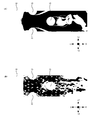
- FIG. 5A shows the distribution of the friction coefficient on the lower surface of the heat radiation fin 14
- FIG. 5B shows the distribution of the friction coefficient on the upper surface of the heat radiation fin 14.
- the intensity of color indicates the magnitude of the coefficient of friction.
- the fluid is kept in a laminar flow state on the upper surface of the heat radiating fin 14 along the upper surface of the heat radiating fin 14. It flows well without peeling. Therefore, heat transfer between the heat radiation fin 14 and the fluid can be promoted.
- FIG. 6A shows the change in the flow field when the heat radiation fin 14 is a flat plate
- FIG. 6B shows the change in the flow field due to the heat radiation fin 14 on which the convex portion 13 is formed. Shown.
- the efficiency of heat exchange between the heat radiation fin 14 and the fluid is low in the light-colored region.
- a large wake region is formed in the rear portion (the portion surrounded by a white circle) of the heat transfer tube 15, and the efficiency of heat exchange is reduced. This is because the surface of the heat radiating fins 14 is flat, so that heat transfer is not satisfactorily performed between the surface of the heat radiating fins 14 and the fluid behind the heat transfer tube 15.
- the wake region as shown in FIG. 6 (A) does not occur in the rear portion (the portion surrounded by the white circle) of the heat transfer tube 15, and the heat exchange is performed well. ing. This is because, as described above, by forming the convex portion 13 having a predetermined shape on the surface of the heat radiating fin 14, the fluid flows well behind the heat transfer tube 15, and between the surface of the heat radiating fin 14 and the fluid. It shows that heat transfer is performed well.
- FIG. 7A is a diagram showing the correlation between the Reynolds number of the fluid that exchanges heat with the heat radiation fins and the j factor
- FIG. 7B is a diagram showing the correlation between the Reynolds number of the fluid and the factor f. ..
- factor j shows heat transfer characteristics
- factor f shows pressure loss.
- the horizontal axis represents the Reynolds number and the vertical axis represents the j factor.
- the characteristics of heat radiation fins of various shapes are shown, the solid line shows the characteristics of plain fins, the coarse dotted line shows the characteristics of louver fins, the dense dotted line shows the characteristics of slit fins, and the alternate long and short dash line shows the characteristics of slit fins.
- the characteristic of the wavy fin is shown, and the alternate long and short dash line shows the characteristic of the fin with dimples formed.
- the j factor is measured under the condition that the Reynolds number has a specific value, and the value of the plain fin under such a condition is indicated by a “white circle”, and the wave-shaped fin (wave-shaped part) is shown.
- the value of (when is 2) is indicated by a “black circle”, and the value of the wave-shaped fin (when the wave-shaped portion is 4) is indicated by a “black-painted square”, and the heat radiation fin having the shape according to the present embodiment is indicated. Is indicated by a "black-painted triangle”.
- the horizontal axis shows the Reynolds number and the vertical axis shows the f factor.
- the solid line shows the characteristics of the plain fins
- the coarse dotted line shows the characteristics of the louver fins
- the dense dotted line shows the characteristics of the slit fins
- the alternate long and short dash line shows the characteristics of the wavy fins.
- the two-dot chain line shows the characteristics of the fins on which the dimples are formed.
- the heat radiation fin 14 of the present embodiment if the heat radiation fin 14 of the present embodiment is adopted, the j factor can be increased by 107% as compared with the plain fin, while the increase of the f factor can be suppressed to 78%. It is possible to suppress an increase in pressure loss while improving thermal performance. Therefore, by adopting the heat radiating fin 14 having such a configuration in the heat exchanger, heat exchange can be effectively performed with a small amount of operating energy. Further, the heat exchanger using the heat radiation fin 14 according to the present embodiment can suppress frost formation and can easily defrost.
- FIG. 9A is a view of the heat exchanger 10 viewed in the Y direction
- FIG. 9B is a view of the heat exchanger 10 viewed in the X direction.
- the basic configuration of the heat exchanger 10 shown here is the same as that shown in FIG. 1, and the heat exchanger 10 is configured as a plate heat exchanger. Has been done.
- the plate heat exchanger a plurality of heat exchangers 10 are stacked and arranged with a predetermined gap. Further, holes 18 through which the pipe through which the fluid flows are formed are formed in the vicinity of the four corners of the heat exchanger 10.
- a high temperature fluid and a low temperature fluid flow for each heat exchanger 10 along the Y-axis direction.
- convex portions 13 are formed at predetermined intervals so as to have a substantially V shape with respect to the flow of the high temperature fluid or the low temperature fluid. By doing so, it is possible to effectively exchange heat between the high temperature fluid and the low temperature fluid and the heat exchanger 10.
- the heat radiation fin 14 here is formed in a substantially corrugated shape.
- 10 (A) is a perspective view showing the heat radiation fin 14, and
- FIG. 10 (B) is a cross-sectional view taken along the line BB of FIG. 10 (A).
- the heat radiation fins 14 When the heat radiation fins 14 are viewed in the Z direction with reference to FIGS. 10 (A) and 10 (B), the heat radiation fins 14 have a corrugated shape along the X direction. A convex portion 13 is formed on the surface of the heat radiating fin 14 facing + X. By doing so, the corrugated heat exchanger 10 can effectively exchange heat with the fluid.
- the high temperature side flow path 22 and the low temperature side flow path 23 are alternately formed along the X direction and sandwiching the heat radiation fin 14. Further, the convex portion 13 is formed so as to project toward the high temperature side flow path 22 and also protrude toward the low temperature side flow path 23.
- the relatively high temperature fluid circulates downward in the high temperature side flow path 22, and the relatively low temperature fluid circulates upward in the low temperature side flow path 23. By doing so, it is possible to effectively exchange heat between the high temperature fluid flowing through the high temperature side flow path 22 and the low temperature fluid flowing through the low temperature side flow path 23 via the heat radiation fins 14.
- FIG. 11A and 11B are views showing a heat exchanger 10 having a housing 19, FIG. 11A is a perspective view showing the heat exchanger 10, and FIG. 11B is an upper surface showing the heat radiation fins 14 extracted. It is a figure.
- the heat radiation fin 14 is housed in the housing 19.
- an introduction port 20 is formed on the lower end side
- an discharge port 21 is formed on the upper end side.
- the low-temperature fluid is introduced into the housing 19 from the introduction port 20, and the low-temperature fluid after heat exchange with the heat radiation fins 14 is discharged to the outside from the discharge port 21.
- an introduction port and a discharge port are also formed on the + Y side of the housing 19, a high temperature fluid is introduced into the housing 19 from the introduction port, and the high temperature fluid that has exchanged heat with the heat radiation fin 14 is discharged. It is discharged to the outside from the outlet.
- the heat radiation fin 14 described above can be applied to other than the heat exchanger 10, and can be applied to, for example, a orthogonal flow type heat exchanger, an automobile-related heat exchanger, that is, a condenser, an evaporator, a radiator, or the like. ..
Landscapes
- Engineering & Computer Science (AREA)
- Physics & Mathematics (AREA)
- Thermal Sciences (AREA)
- Mechanical Engineering (AREA)
- General Engineering & Computer Science (AREA)
- Geometry (AREA)
- Heat-Exchange Devices With Radiators And Conduit Assemblies (AREA)
Priority Applications (4)
| Application Number | Priority Date | Filing Date | Title |
|---|---|---|---|
| JP2021535475A JP7569524B2 (ja) | 2019-07-26 | 2020-09-23 | 熱交換促進部材および熱交換器 |
| US17/629,887 US20220373270A1 (en) | 2019-07-26 | 2020-09-23 | Heat exchange promotion member and heat exchanger |
| CN202080054097.8A CN114556041B (zh) | 2019-07-26 | 2020-09-23 | 热交换促进部件以及热交换器 |
| US18/908,257 US12529529B2 (en) | 2019-07-26 | 2024-10-07 | Heat exchange promotion member and heat exchanger |
Applications Claiming Priority (2)
| Application Number | Priority Date | Filing Date | Title |
|---|---|---|---|
| JP2019-137663 | 2019-07-26 | ||
| JP2019137663 | 2019-07-26 |
Related Child Applications (2)
| Application Number | Title | Priority Date | Filing Date |
|---|---|---|---|
| US17/629,887 A-371-Of-International US20220373270A1 (en) | 2019-07-26 | 2020-09-23 | Heat exchange promotion member and heat exchanger |
| US18/908,257 Continuation US12529529B2 (en) | 2019-07-26 | 2024-10-07 | Heat exchange promotion member and heat exchanger |
Publications (1)
| Publication Number | Publication Date |
|---|---|
| WO2021020592A1 true WO2021020592A1 (ja) | 2021-02-04 |
Family
ID=74228985
Family Applications (1)
| Application Number | Title | Priority Date | Filing Date |
|---|---|---|---|
| PCT/JP2020/035727 Ceased WO2021020592A1 (ja) | 2019-07-26 | 2020-09-23 | 熱交換促進部材および熱交換器 |
Country Status (4)
| Country | Link |
|---|---|
| US (2) | US20220373270A1 (https=) |
| JP (1) | JP7569524B2 (https=) |
| CN (1) | CN114556041B (https=) |
| WO (1) | WO2021020592A1 (https=) |
Families Citing this family (1)
| Publication number | Priority date | Publication date | Assignee | Title |
|---|---|---|---|---|
| CN115884563B (zh) * | 2021-09-27 | 2025-04-01 | 中兴智能科技南京有限公司 | 散热组件及散热器 |
Citations (5)
| Publication number | Priority date | Publication date | Assignee | Title |
|---|---|---|---|---|
| JPS5883687U (ja) * | 1981-12-02 | 1983-06-06 | 松下電器産業株式会社 | フイン付熱交換器 |
| JPH0476395A (ja) * | 1990-07-17 | 1992-03-11 | Kenzo Kitamura | 自然対流の伝熱促進方法 |
| JPH0763490A (ja) * | 1993-08-26 | 1995-03-10 | Mitsubishi Heavy Ind Ltd | プレートフィンアンドチューブ型熱交換器 |
| WO2007013623A1 (ja) * | 2005-07-29 | 2007-02-01 | The University Of Tokyo | 熱交換器およびこれを用いた空気調和装置並びに空気性状変換器 |
| WO2012102053A1 (ja) * | 2011-01-27 | 2012-08-02 | パナソニック株式会社 | フィンチューブ型熱交換器 |
Family Cites Families (29)
| Publication number | Priority date | Publication date | Assignee | Title |
|---|---|---|---|---|
| DE496733C (de) * | 1928-10-27 | 1930-04-24 | E H Hugo Junkers Dr Ing | Rippenrohr-Waermeaustauschvorrichtung mit aus Blech von ueberall gleicher Dicke hergestellten Rippen |
| US3515207A (en) * | 1968-07-17 | 1970-06-02 | Perfex Corp | Fin configuration for fin and tube heat exchanger |
| JPS55105786U (https=) | 1979-01-11 | 1980-07-24 | ||
| US4332291A (en) * | 1979-12-21 | 1982-06-01 | D. Mulock-Bentley And Associates (Proprietary) Limited | Heat exchanger with slotted fin strips |
| NL8100334A (nl) * | 1980-01-28 | 1981-08-17 | Lummus Co | Buis met plaatvormige ribben en warmtewisselaar die met zulke ribben is uitgerust. |
| JPS62123293A (ja) | 1985-11-20 | 1987-06-04 | Matsushita Electric Ind Co Ltd | フイン付熱交換器 |
| JPH02309195A (ja) | 1989-05-23 | 1990-12-25 | Sanyo Electric Co Ltd | 熱交換器及びその製造方法 |
| JPH0517366U (ja) | 1991-08-06 | 1993-03-05 | 東洋ラジエーター株式会社 | 熱交換器のプレートフイン |
| JPH08170890A (ja) | 1994-12-16 | 1996-07-02 | Daikin Ind Ltd | クロスフィン熱交換器 |
| US6127571A (en) * | 1997-11-11 | 2000-10-03 | Uop Llc | Controlled reactant injection with permeable plates |
| JP2000193389A (ja) * | 1998-12-28 | 2000-07-14 | Hitachi Ltd | 空気調和機の室外ユニット |
| US6595273B2 (en) * | 2001-08-08 | 2003-07-22 | Denso Corporation | Heat exchanger |
| US6615910B1 (en) * | 2002-02-20 | 2003-09-09 | Delphi Technologies, Inc. | Advanced air cooled heat sink |
| US6889759B2 (en) * | 2003-06-25 | 2005-05-10 | Evapco, Inc. | Fin for heat exchanger coil assembly |
| US7159649B2 (en) * | 2004-03-11 | 2007-01-09 | Thermal Corp. | Air-to-air heat exchanger |
| JP5039366B2 (ja) * | 2006-11-21 | 2012-10-03 | 三菱重工業株式会社 | フィンアンドチューブ型熱交換器 |
| US7475719B2 (en) * | 2006-12-14 | 2009-01-13 | Evapco, Inc. | High-frequency, low-amplitude corrugated fin for a heat exchanger coil assembly |
| CN101589285B (zh) * | 2007-01-25 | 2011-10-26 | 国立大学法人东京大学 | 热交换器 |
| JP5077926B2 (ja) | 2007-01-25 | 2012-11-21 | 国立大学法人 東京大学 | 熱交換器 |
| JP5082120B2 (ja) * | 2007-03-23 | 2012-11-28 | 国立大学法人 東京大学 | 熱交換器 |
| FR2940422B1 (fr) * | 2008-12-19 | 2010-12-03 | Gea Batignolles Technologies T | Echangeur de chaleur comprenant des tubes a ailettes rainurees |
| EP2299488B1 (en) * | 2009-08-06 | 2014-07-23 | Cpumate Inc. | Heat-dissipating fin assembly with heat-conducting structure |
| JP5156773B2 (ja) * | 2010-02-25 | 2013-03-06 | 株式会社小松製作所 | コルゲートフィンおよびそれを備える熱交換器 |
| US9080819B2 (en) * | 2011-10-05 | 2015-07-14 | T.Rad Co., Ltd. | Folded heat exchanger with V-shaped convex portions |
| JP6206975B2 (ja) * | 2012-11-15 | 2017-10-04 | 国立大学法人 東京大学 | 熱交換器 |
| JP3199776U (ja) | 2015-06-26 | 2015-09-10 | 有限会社和氣製作所 | 熱交換器 |
| JP2018017465A (ja) | 2016-07-28 | 2018-02-01 | 株式会社ティラド | コルゲートフィン型熱交換器コア |
| CN109470075B (zh) * | 2017-09-08 | 2024-04-30 | 美的集团股份有限公司 | 翅片和换热器 |
| JP2025149592A (ja) | 2024-03-26 | 2025-10-08 | 日本ゼオン株式会社 | 電極活物質層の製造方法及び製造装置 |
-
2020
- 2020-09-23 US US17/629,887 patent/US20220373270A1/en not_active Abandoned
- 2020-09-23 JP JP2021535475A patent/JP7569524B2/ja active Active
- 2020-09-23 CN CN202080054097.8A patent/CN114556041B/zh active Active
- 2020-09-23 WO PCT/JP2020/035727 patent/WO2021020592A1/ja not_active Ceased
-
2024
- 2024-10-07 US US18/908,257 patent/US12529529B2/en active Active
Patent Citations (5)
| Publication number | Priority date | Publication date | Assignee | Title |
|---|---|---|---|---|
| JPS5883687U (ja) * | 1981-12-02 | 1983-06-06 | 松下電器産業株式会社 | フイン付熱交換器 |
| JPH0476395A (ja) * | 1990-07-17 | 1992-03-11 | Kenzo Kitamura | 自然対流の伝熱促進方法 |
| JPH0763490A (ja) * | 1993-08-26 | 1995-03-10 | Mitsubishi Heavy Ind Ltd | プレートフィンアンドチューブ型熱交換器 |
| WO2007013623A1 (ja) * | 2005-07-29 | 2007-02-01 | The University Of Tokyo | 熱交換器およびこれを用いた空気調和装置並びに空気性状変換器 |
| WO2012102053A1 (ja) * | 2011-01-27 | 2012-08-02 | パナソニック株式会社 | フィンチューブ型熱交換器 |
Also Published As
| Publication number | Publication date |
|---|---|
| JP7569524B2 (ja) | 2024-10-18 |
| CN114556041A (zh) | 2022-05-27 |
| US20220373270A1 (en) | 2022-11-24 |
| CN114556041B (zh) | 2024-06-25 |
| US12529529B2 (en) | 2026-01-20 |
| US20250027727A1 (en) | 2025-01-23 |
| JPWO2021020592A1 (https=) | 2021-02-04 |
Similar Documents
| Publication | Publication Date | Title |
|---|---|---|
| US9459053B2 (en) | Heat exchanger and air-conditioning apparatus | |
| US6308527B1 (en) | Refrigerant evaporator with condensed water drain structure | |
| JP6711813B2 (ja) | 熱交換器、熱交換モジュール、熱交換装置、及び熱源ユニット | |
| CN101995115B (zh) | 多通道热交换器散热片 | |
| US10077956B2 (en) | Heat exchanger with enhanced airflow | |
| EP3021064B1 (en) | Heat pump device | |
| CN107990758B (zh) | 换热器和热泵系统 | |
| CN101782347B (zh) | 热交换器及其翅片 | |
| KR102413374B1 (ko) | 낮은 레이놀즈 수 공기 흐름을 위한 핀 향상 | |
| JPH09189493A (ja) | フィン付き形熱交換器 | |
| EP2447660A2 (en) | Heat Exchanger and Micro-Channel Tube Thereof | |
| US12529529B2 (en) | Heat exchange promotion member and heat exchanger | |
| CN219713699U (zh) | 一种空调器 | |
| CN111902683A (zh) | 热交换器及制冷循环装置 | |
| CN114322105B (zh) | 换热器和空调系统 | |
| JP7006376B2 (ja) | 熱交換器 | |
| EP2224198A1 (en) | Fin and tube type heat exchanger | |
| EP4300026A1 (en) | Heat exchange fin, heat exchanger, and heat pump system | |
| JP6379352B2 (ja) | フィンチューブ熱交換器 | |
| JP6230852B2 (ja) | 空気調和機及び空気調和機用熱交換器 | |
| JP2012154520A (ja) | 熱交換器用チューブ及び熱交換器 | |
| JPH09196585A (ja) | フィン付き形熱交換器 | |
| JP2008070106A (ja) | 空調冷却システムにおける凝縮器および放熱器 | |
| CN106802029A (zh) | 换热器芯体和具有它的换热器 | |
| CN223596247U (zh) | 换热器及冰箱 |
Legal Events
| Date | Code | Title | Description |
|---|---|---|---|
| 121 | Ep: the epo has been informed by wipo that ep was designated in this application |
Ref document number: 20847869 Country of ref document: EP Kind code of ref document: A1 |
|
| DPE1 | Request for preliminary examination filed after expiration of 19th month from priority date (pct application filed from 20040101) | ||
| ENP | Entry into the national phase |
Ref document number: 2021535475 Country of ref document: JP Kind code of ref document: A |
|
| NENP | Non-entry into the national phase |
Ref country code: DE |
|
| 122 | Ep: pct application non-entry in european phase |
Ref document number: 20847869 Country of ref document: EP Kind code of ref document: A1 |