WO2021020122A1 - 配線部材 - Google Patents
配線部材 Download PDFInfo
- Publication number
- WO2021020122A1 WO2021020122A1 PCT/JP2020/027459 JP2020027459W WO2021020122A1 WO 2021020122 A1 WO2021020122 A1 WO 2021020122A1 JP 2020027459 W JP2020027459 W JP 2020027459W WO 2021020122 A1 WO2021020122 A1 WO 2021020122A1
- Authority
- WO
- WIPO (PCT)
- Prior art keywords
- electric wire
- metal sheet
- resin portion
- fixed
- layer
- Prior art date
- Legal status (The legal status is an assumption and is not a legal conclusion. Google has not performed a legal analysis and makes no representation as to the accuracy of the status listed.)
- Ceased
Links
Images


Classifications
-
- H—ELECTRICITY
- H01—ELECTRIC ELEMENTS
- H01B—CABLES; CONDUCTORS; INSULATORS; SELECTION OF MATERIALS FOR THEIR CONDUCTIVE, INSULATING OR DIELECTRIC PROPERTIES
- H01B7/00—Insulated conductors or cables characterised by their form
- H01B7/42—Insulated conductors or cables characterised by their form with arrangements for heat dissipation or conduction
-
- H—ELECTRICITY
- H02—GENERATION; CONVERSION OR DISTRIBUTION OF ELECTRIC POWER
- H02G—INSTALLATION OF ELECTRIC CABLES OR LINES, OR OF COMBINED OPTICAL AND ELECTRIC CABLES OR LINES
- H02G3/00—Installations of electric cables or lines or protective tubing therefor in or on buildings, equivalent structures or vehicles
- H02G3/02—Details
- H02G3/04—Protective tubing or conduits, e.g. cable ladders or cable troughs
-
- B—PERFORMING OPERATIONS; TRANSPORTING
- B60—VEHICLES IN GENERAL
- B60R—VEHICLES, VEHICLE FITTINGS, OR VEHICLE PARTS, NOT OTHERWISE PROVIDED FOR
- B60R16/00—Electric or fluid circuits specially adapted for vehicles and not otherwise provided for; Arrangement of elements of electric or fluid circuits specially adapted for vehicles and not otherwise provided for
- B60R16/02—Electric or fluid circuits specially adapted for vehicles and not otherwise provided for; Arrangement of elements of electric or fluid circuits specially adapted for vehicles and not otherwise provided for electric constitutive elements
- B60R16/0207—Wire harnesses
-
- B—PERFORMING OPERATIONS; TRANSPORTING
- B60—VEHICLES IN GENERAL
- B60R—VEHICLES, VEHICLE FITTINGS, OR VEHICLE PARTS, NOT OTHERWISE PROVIDED FOR
- B60R16/00—Electric or fluid circuits specially adapted for vehicles and not otherwise provided for; Arrangement of elements of electric or fluid circuits specially adapted for vehicles and not otherwise provided for
- B60R16/02—Electric or fluid circuits specially adapted for vehicles and not otherwise provided for; Arrangement of elements of electric or fluid circuits specially adapted for vehicles and not otherwise provided for electric constitutive elements
- B60R16/0207—Wire harnesses
- B60R16/0215—Protecting, fastening and routing means therefor
-
- H—ELECTRICITY
- H01—ELECTRIC ELEMENTS
- H01B—CABLES; CONDUCTORS; INSULATORS; SELECTION OF MATERIALS FOR THEIR CONDUCTIVE, INSULATING OR DIELECTRIC PROPERTIES
- H01B7/00—Insulated conductors or cables characterised by their form
- H01B7/40—Insulated conductors or cables characterised by their form with arrangements for facilitating mounting or securing
-
- H—ELECTRICITY
- H01—ELECTRIC ELEMENTS
- H01B—CABLES; CONDUCTORS; INSULATORS; SELECTION OF MATERIALS FOR THEIR CONDUCTIVE, INSULATING OR DIELECTRIC PROPERTIES
- H01B7/00—Insulated conductors or cables characterised by their form
- H01B7/42—Insulated conductors or cables characterised by their form with arrangements for heat dissipation or conduction
- H01B7/428—Heat conduction
-
- H—ELECTRICITY
- H02—GENERATION; CONVERSION OR DISTRIBUTION OF ELECTRIC POWER
- H02G—INSTALLATION OF ELECTRIC CABLES OR LINES, OR OF COMBINED OPTICAL AND ELECTRIC CABLES OR LINES
- H02G3/00—Installations of electric cables or lines or protective tubing therefor in or on buildings, equivalent structures or vehicles
- H02G3/02—Details
- H02G3/03—Cooling
-
- H—ELECTRICITY
- H02—GENERATION; CONVERSION OR DISTRIBUTION OF ELECTRIC POWER
- H02G—INSTALLATION OF ELECTRIC CABLES OR LINES, OR OF COMBINED OPTICAL AND ELECTRIC CABLES OR LINES
- H02G3/00—Installations of electric cables or lines or protective tubing therefor in or on buildings, equivalent structures or vehicles
- H02G3/02—Details
- H02G3/04—Protective tubing or conduits, e.g. cable ladders or cable troughs
- H02G3/0456—Ladders or other supports
-
- H—ELECTRICITY
- H01—ELECTRIC ELEMENTS
- H01B—CABLES; CONDUCTORS; INSULATORS; SELECTION OF MATERIALS FOR THEIR CONDUCTIVE, INSULATING OR DIELECTRIC PROPERTIES
- H01B7/00—Insulated conductors or cables characterised by their form
- H01B7/08—Flat or ribbon cables
Definitions
- This disclosure relates to wiring members.
- Patent Document 1 discloses a wire harness in which an electric wire is welded to a functional exterior member formed in a sheet shape.
- the purpose is to provide a technology that facilitates heat dissipation of electric wires.
- the wiring member of the present disclosure is a wiring member including an electric wire, a metal sheet, and a fixed resin portion containing a resin as a main component, and the fixed resin portion fixes the electric wire to the metal sheet.
- the heat of the electric wire is easily dissipated.
- FIG. 1 is a perspective view showing a wiring member according to the first embodiment.
- FIG. 2 is a cross-sectional view taken along the line II-II in FIG.
- FIG. 3 is an exploded perspective view showing a modified example of the metal sheet.
- FIG. 4 is a cross-sectional view showing a wiring member according to the second embodiment.
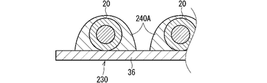
- FIG. 5 is a cross-sectional view showing a modified example of the fixed resin portion.
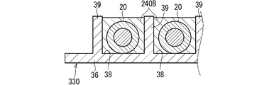
- FIG. 6 is a cross-sectional view showing another modified example of the fixed resin portion.
- the wiring members of this disclosure are as follows.
- a wiring member including an electric wire, a metal sheet, and a fixed resin portion containing a resin as a main component, and the fixed resin portion fixes the electric wire to the metal sheet. As a result, the heat of the electric wire is easily dissipated through the metal sheet.
- the fixed resin portion may contain a filler having a higher thermal conductivity than the resin. As a result, the thermal conductivity of the fixed resin portion is enhanced, and the heat of the electric wire is easily transferred to the metal sheet.
- the fixed resin portion may be formed by an adhesive that adheres the metal sheet and the electric wire. As a result, the electric wire is easily fixed to the metal sheet by the adhesive.
- the fixed resin portion is a fusion layer laminated on the metal sheet, and the electric wire may be fused to the fusion layer. As a result, the electric wire is easily fixed to the metal sheet by the fusion layer.
- the metal sheet includes a porous layer formed in a porous manner, and a part of the fixed resin portion may enter the voids in the porous layer. As a result, the fixing resin portion is satisfactorily fixed to the porous layer by the anchor effect.
- the metal sheet further includes a plate-like layer laminated on the porous layer, and the plate-like layer is formed in a shape in which the inside is uniformly buried, and the electric wire is formed with respect to the porous layer. It may be laminated on the opposite side.
- the plate-like layer can prevent the resin of the fixed resin portion from reaching the back surface of the metal sheet from the surface on the electric wire side.
- the electric wire has an end portion extending outward from the metal sheet, and the fixed resin portion has a second higher thermal conductivity than the first fixed resin portion and the first fixed resin portion.
- the portion of the electric wire fixed by the second fixed resin portion, including the fixed resin portion, may be closer to the end portion than the portion fixed by the first fixed resin portion.
- FIG. 1 is a perspective view showing a wiring member 10 according to the first embodiment.
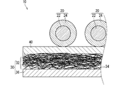
- FIG. 2 is a cross-sectional view taken along the line II-II in FIG.
- the wiring member 10 is mounted on a vehicle, for example.
- the wiring member 10 is used as wiring for connecting electrical components in a vehicle.
- the wiring member 10 includes an electric wire 20, a metal sheet 30, and a fixed resin portion 40.
- the fixing resin portion 40 fixes the electric wire 20 to the metal sheet 30.
- the electric wire 20 includes one or a plurality of electric wires.
- the electric wire 20 includes a core wire 22 and a coating layer 24.
- the core wire 22 has one or a plurality of strands.
- the strands are formed linearly using a conductor such as copper alloy, aluminum, or aluminum alloy as a material.
- the plurality of strands may or may not be twisted.
- the coating layer 24 covers the core wire 22.
- the coating layer 24 is formed of an insulating material such as resin.
- the coating layer 24 may be a molten material extruded around the core wire 22.
- the coating layer 24 may be one in which an insulating paint or the like is applied around the core wire 22.
- the electric wire 20 is a single wire.
- the electric wire may be a multi-core cable.
- the multi-core cable is formed in a shape in which a second coating layer (also referred to as a sheath, jacket, etc.) is provided around a plurality of single wires each including a core wire 22 and a coating layer 24.
- the electric wire may be a shielded wire, a twisted wire, an enamel wire, a nichrome wire, a coaxial wire, or the like.
- the plurality of electric wires 20 may be arranged in a plane on the metal sheet 30. As a result, the wiring member 10 is formed in a flat shape as a whole.
- the plurality of electric wires 20 may extend on the metal sheet 30 along a route corresponding to the route of the electric wires 20 in the vehicle.
- the plurality of electric wires 20 may include electric wires that bend on the metal sheet 30.
- the plurality of electric wires 20 may include electric wires branched on the metal sheet 30. That is, it is preferable that the branch portion is provided on the metal sheet 30.
- the electric wire 20 has an end extending outward from the metal sheet 30.
- a connector C is provided at the end of the electric wire 20.
- the connector C is formed by accommodating the end portion of the electric wire 20 in the housing.
- a terminal or the like may be connected to the end of the electric wire 20.
- a portion of the electric wire 20 that is not fixed to the metal sheet 30 (hereinafter, referred to as an electric wire floating portion) is formed between the portion that is housed in the housing and the portion that is fixed to the metal sheet 30.
- the metal sheet 30 includes a porous layer 32 and a plate-like layer 36.
- the material constituting the metal sheet 30 is not particularly limited.
- the material constituting the metal sheet 30 may be, for example, iron, stainless steel, aluminum, an aluminum alloy, copper, a copper alloy, or the like.
- the material constituting the porous layer 32 and the material constituting the plate-like layer 36 may be the same material or may be different materials.
- the porous layer 32 is a layer formed in a porous manner. Porous means that there are many small pores through which gas and liquid can pass. This pore penetrates the porous layer 32 in the front-back direction. Gas and liquid can pass through the porous layer 32 in the front and back directions.
- the porous layer 32 is a fiber layer in which metal fibers 34 are aggregated.
- the fiber layer is formed in the form of a non-woven fabric in which a large number of metal fibers 34 are randomly assembled.
- the fiber diameter of the metal fiber 34 may be, for example, 10 micrometers or more and 250 micrometers or less.
- the basis weight of the fiber layer may be, for example, 100 g / m2 or more and 5000 g / m2 or less.
- the thickness of the fiber layer may be 0.05 mm or more and 5.0 mm or less.
- the fiber layer may be a woven cloth, a knitted cloth, or the like formed by weaving or knitting metal fibers 34.
- the metal fiber 34 may not contain a single metal, that is, a resin material or the like.
- the metal fiber 34 may contain a resin material or the like in addition to the metal material.
- the metal fiber 34 may be a resin fiber whose surface is coated with a metal material.
- the porous layer 32 does not have to be a fiber layer.
- the porous layer 132 may be a mesh layer as in the metal sheet 130 according to the modification shown in FIG.
- the wire diameter of the metal wire constituting the mesh layer may be, for example, 0.010 mm or more and 2.0 mm or less.
- the mesh (the number of meshes contained in a square having a side of 1 inch) may be, for example, 2 or more and 2400 or less.
- the opening in the mesh layer may be, for example, 0.001 mm or more and 16 mm or less.
- the porous layer may be a plate-like member whose inside is uniformly filled with a plurality of holes.
- the plate-like layer 36 is laminated on the porous layer 32.
- the plate-like layer 36 is laminated on the side opposite to the electric wire 20 with respect to the porous layer 32.
- the plate-like layer 36 is a layer through which gases and liquids are less likely to pass than the porous layer 32.
- the plate-like layer 36 is formed in a shape in which the inside is uniformly filled. No through hole is formed in the plate-like layer 36.
- the plate-like layer 36 may contain air bubbles or the like generated in the manufacturing process.
- the plate-like layer 36 may be, for example, a metal foil.
- the porous layer 32 and the plate-like layer 36 are joined. As a result, the porous layer 32 and the plate-like layer 36 are maintained in a laminated state. For example, the portion of the metal material constituting the porous layer 32 that is in contact with the surface of the plate-like layer 36 is welded or sintered with the metal material constituting the plate-like layer 36, so that the porous layer 32 and the plate-like portion are formed. The layer 36 is joined.
- the metal sheet 30 is formed in a size capable of including the path of the electric wire 20.
- the metal sheet 30 may be formed so as to be bent or branched according to the path of the electric wire 20.
- the fixed resin portion 40 is formed mainly of resin.
- the fixing resin portion 40 fixes the electric wire 20 to the metal sheet 30.
- the fixed resin part 40 contains a filler.
- the filler has higher thermal conductivity than the resin that is the main component of the fixed resin portion 40.
- the filler may contain an inorganic filler or may contain a metal filler.
- the material of the inorganic filler may be silica, aluminum oxide, magnesium oxide, beryllium oxide, boron nitride, aluminum nitride, silicon nitride, silicon carbide, boron carbide, titanium carbide, mullite, graphite, carbon nanotubes and the like.
- the material of the metal filler may be copper, aluminum, silver, iron or the like.
- the fixed resin portion 40 includes a first fixed resin portion 42 and a second fixed resin portion 44.
- the second fixed resin portion 44 has higher thermal conductivity than the first fixed resin portion 42. It is sufficient that the second fixed resin portion 44 has higher thermal conductivity than the first fixed resin portion 42 in a state where the first fixed resin portion 42 and the second fixed resin portion 44 have the shape of the wiring member 10. ..
- the second fixed resin portion 44 may have higher thermal conductivity than the first fixed resin portion 42.
- the second fixed resin portion 44 may have higher thermal conductivity than the first fixed resin portion 42 because the type of the resin as the main component is different. Further, for example, the second fixed resin portion 44 may have higher thermal conductivity than the first fixed resin portion 42 because the type and amount of the filler are different.
- the portion of the electric wire 20 fixed by the second fixed resin portion 44 is closer to the end than the portion of the electric wire 20 fixed by the first fixed resin portion 42. As described above, an electric wire floating portion is formed between the end portion of the electric wire 20 housed in the housing and the portion fixed to the metal sheet 30. The portion of the electric wire 20 fixed by the second fixed resin portion 44 is closer to the electric wire floating portion than the portion of the electric wire 20 fixed by the first fixed resin portion 42.
- the second fixed resin portion 44 By providing the second fixed resin portion 44, heat is less likely to accumulate in the wire floating portion. More specifically, since the thermal conductivity of the second fixed resin portion 44 is enhanced, the heat of the portion of the electric wire 20 in contact with the second fixed resin portion 44 is easily transferred to the metal sheet 30. As a result, the temperature of the portion of the electric wire 20 in contact with the second fixed resin portion 44 is less likely to rise than the temperature of the floating portion of the electric wire. As a result, the heat generated in the floating portion of the electric wire is easily transferred to the portion of the electric wire 20 in contact with the second fixed resin portion 44, and the heat is less likely to be accumulated in the floating portion of the electric wire.
- the fixed resin portion 40 is a fusion layer.
- the fusion layer is laminated on the metal sheet 30.
- the fused layer is laminated on the porous layer 32. A part of the fused layer has entered the voids in the porous layer 32. As a result, the fused layer is maintained in a state of being laminated on the porous layer 32.
- the electric wire 20 is fused to the fusion layer.
- the electric wire 20 is fused to the fusion layer as follows, for example. That is, ultrasonic welding, heat and pressure welding, and the like are performed in a state where the electric wire 20 is arranged on the welding layer provided on the metal sheet 30. As a result, at least one of the resin constituting the fusion layer and the resin constituting the coating layer 24 is melted, bonded to the mating side, and solidified.
- the resin material constituting the fusion layer may be a material having compatibility with the resin constituting the coating layer 24, such as a resin material similar to the resin constituting the coating layer 24.
- the fusion layer may also be PVC.
- the coating layer 24 is a polyolefin
- the fusion layer may also be a polyolefin.
- the fused layer may be provided in the entire region of the main surface of the metal sheet 30.
- the fused layer may be provided in a part of the main surface of the metal sheet 30.
- a fusion layer is also present between the parallel electric wires 20.
- the entire region of the electric wire 20 on the metal sheet 30 may be fixed to the metal sheet 30 via a fusion layer.
- a part of the electric wire 20 on the metal sheet 30 may be fixed to the metal sheet 30 via a fusion layer.
- a part of the electric wire 20 on the metal sheet 30 is fixed to the metal sheet 30 via the fusion layer. You may be.
- a part of the electric wire 20 on the metal sheet 30 may be fixed to the metal sheet 30 via the fusion layer. .. That is, in the portion where the electric wire 20 and the metal sheet 30 are not fixed, a fused layer may or may not be interposed between the electric wire 20 and the metal sheet 30.
- the fixing area can be appropriately set.
- the electric wire 20 may be intermittently fixed to the metal sheet 30 via the cohesive layer along the longitudinal direction of the electric wire 20.
- the electric wire 20 and the metal sheet 30 are not in contact with each other in the portion of the electric wire 20 fixed to the metal sheet 30 by the fixing resin portion 40. That is, in the portion of the electric wire 20 fixed to the metal sheet 30 by the fixing resin portion 40, the fixing resin portion 40 is interposed between the electric wire 20 and the metal sheet 30. However, the electric wire 20 and the metal sheet 30 may be in contact with each other in the portion of the electric wire 20 fixed to the metal sheet 30 by the fixing resin portion 40. For example, when the electric wire 20 is fused to the fusion layer, all the portions of the fusion layer that are interposed between the electric wire 20 and the metal sheet 30 are melted, and the electric wire 20 is fused so as to be in contact with the metal sheet 30. You may be.
- the fixed resin portion 40 contains a filler, the thermal conductivity of the fixed resin portion 40 is enhanced, and the heat of the electric wire 20 is easily transferred to the metal sheet 30. Further, the electric wire 20 is easily fixed to the metal sheet 30 by the fusion layer.
- the fixing resin portion 40 is satisfactorily fixed to the porous layer 32 by the anchor effect. Further, since the metal sheet 30 further includes the plate-shaped layer 36, the plate-shaped layer 36 can prevent the resin of the fixing resin portion 40 from reaching the back surface of the metal sheet 30 from the surface on the electric wire 20 side.
- the portion of the electric wire 20 fixed by the second fixed resin portion 44 is closer to the end than the portion fixed by the first fixed resin portion 42, the portion of the electric wire 20 is moved outward from the metal sheet 30. The heat generated in the extending portion is easily dissipated through the second fixed resin portion 44.
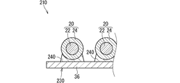
- FIG. 4 is a cross-sectional view showing the wiring member 210 according to the second embodiment.
- the same reference numerals will be given to the components as described above, and the description thereof will be omitted.
- the wiring member 210 is different from the wiring member 10 in that the fixed resin portion 240 is an adhesive.
- the adhesive adheres the metal sheet 230 and the electric wire 20.
- the wiring member 210 is different from the wiring member 10 in that the fixing resin portion 240 is fixed to the plate-like layer 36 of the metal sheet 230.
- the metal sheet 230 does not include the porous layer 32.
- the fixing resin portion 240 may be fixed to the plate-like layer 36 in the metal sheet 30 including the porous layer 32.
- the resin material constituting the adhesive may be selected according to the mode of adhesion to the electric wire 20, the mode of adhesion to the metal sheet 230, the material of the electric wire 20, the material of the metal sheet 230, and the like.
- the resin material constituting the adhesive may be a thermoplastic resin or a thermosetting resin.
- the resin material constituting the adhesive may be, for example, an epoxy resin, a silicone, a modified silicone, an acrylic resin, a cyanoacrylate resin, or the like.
- the adhesive may also contain a filler.
- the adhesive and the coating layer 24 may be bonded by a physical action such as an anchor effect, or may be bonded by a chemical action such as a chemical bond.
- the adhesive and the metal sheet 230 may be bonded by a physical action such as an anchor effect, or may be bonded by a chemical action such as a chemical bond.
- the fixed resin portion 240 contains a compound containing a metal-side reactive group and a resin-side reactive group.
- the metal-side reactive group is a reactive group that chemically bonds with the metal material constituting the metal sheet 30.
- the metal-side reactive group is, for example, an alkoxy group.
- the resin-side reactive group is a reactive group that chemically bonds with the resin material constituting the coating layer 24.
- the resin-side reactive group is, for example, an amino group, a thiol group, an epoxy group, a vinyl group, an acrylic group, a methacryl group and the like.
- a compound may be, for example, a silane coupling agent.
- the adhesive is in contact with only a part around the electric wire 20.
- the adhesive may be adhered to both the electric wire 20 and the metal sheet 230. Further, in this case, it is preferable that the adhesive is provided on the entire portion of the circumference of the electric wire 20 facing the metal sheet 230.
- the adhesive constituting the fixed resin portion 240A may wrap the entire circumference of the electric wire 20.
- the adhesive may be adhered to the metal sheet 230.
- the adhesive may or may not be adhered to the electric wire 20.
- a groove 38 in which the electric wire 20 is accommodated may be formed in the metal sheet 330. Then, the groove 38 may be filled with the adhesive constituting the fixed resin portion 240B. In this case, the adhesive may be adhered to the metal sheet 330. The adhesive may or may not be adhered to the electric wire 20.
- a plurality of ribs 39 are provided on the main surface of the metal sheet 330 to form a groove 38. However, a part of the main surface of the metal sheet may be recessed to form a groove.
- the wiring member 210 in this example also facilitates heat dissipation of the electric wire 20 through the metal sheet 230. According to the wiring member 210 in this example, the electric wire 20 is easily fixed to the metal sheet 230 by the adhesive.
- the fixed resin portion 40 has been described as including the first fixed resin portion 42 and the second fixed resin portion 44 having different thermal conductivity from each other, but this is not an essential configuration.
- the fixed resin portion 40 on the metal sheet 30 may be formed so as to have uniform thermal conductivity.
- the adhesive may be fixed to the porous layer 32.
- the fusion layer may be provided on the plate-like layer 36.
Landscapes
- Engineering & Computer Science (AREA)
- Architecture (AREA)
- Civil Engineering (AREA)
- Structural Engineering (AREA)
- Mechanical Engineering (AREA)
- Insulated Conductors (AREA)
- Details Of Indoor Wiring (AREA)
- Cooling Or The Like Of Electrical Apparatus (AREA)
- Insertion, Bundling And Securing Of Wires For Electric Apparatuses (AREA)
Abstract
電線の熱が放熱されやすくなる技術を提供することを目的とする。配線部材は、電線と、金属シートと、樹脂を主成分とする固定樹脂部と、を備え、前記固定樹脂部が前記電線を前記金属シートに固定している。
Description
本開示は、配線部材に関する。
特許文献1にはシート状に形成された機能性外装部材に電線が溶着されたワイヤーハーネスが開示されている。
電線の熱が放熱されやすくなることが望まれている。
そこで、電線の熱が放熱されやすくなる技術を提供することを目的とする。
本開示の配線部材は、電線と、金属シートと、樹脂を主成分とする固定樹脂部と、を備え、前記固定樹脂部が前記電線を前記金属シートに固定している、配線部材である。
本開示によれば、電線の熱が放熱されやすくなる。
[本開示の実施形態の説明]
最初に本開示の実施態様を列記して説明する。
最初に本開示の実施態様を列記して説明する。
本開示の配線部材は、次の通りである。
(1)電線と、金属シートと、樹脂を主成分とする固定樹脂部と、を備え、前記固定樹脂部が前記電線を前記金属シートに固定している、配線部材である。これにより、金属シートを介して電線の熱が放熱されやすくなる。
(2)前記固定樹脂部は前記樹脂よりも熱伝導性の高いフィラーを含有していてもよい。これにより、固定樹脂部の熱伝導性が高まり、電線の熱が金属シートに伝わりやすくなる。
(3)前記固定樹脂部は前記金属シート及び前記電線を接着している接着剤によって形成されていてもよい。これにより、接着剤によって電線が金属シートに簡易に固定される。
(4)前記固定樹脂部は前記金属シートに積層された融着層であり、前記電線が前記融着層に融着されていてもよい。これにより、融着層によって電線が金属シートに簡易に固定される。
(5)前記金属シートは、多孔質に形成された多孔質層を含み、前記固定樹脂部の一部が前記多孔質層における空隙に入り込んでいてもよい。これにより、アンカー効果によって固定樹脂部が多孔質層に良好に固定される。
(6)前記金属シートは、前記多孔質層に積層された板状層をさらに含み、前記板状層は、内部が一様に埋まった形状に形成され、前記多孔質層に対して前記電線とは反対側に積層されていてもよい。これにより、固定樹脂部の樹脂が金属シートのうち電線側の面から裏面に達することを板状層が抑制することができる。
(7)前記電線は、前記金属シートから外方に延びる端部を有しており、前記固定樹脂部は、第1固定樹脂部と前記第1固定樹脂部よりも熱伝導性が高い第2固定樹脂部とを含み、前記電線のうち前記第2固定樹脂部によって固定されている部分は、前記第1固定樹脂部によって固定されている部分よりも前記端部に近くてもよい。これにより、電線のうちシートから外方に延びる部分に生じる熱が第2固定樹脂部を介して放熱されやすくなる。
[本開示の実施形態の詳細]
本開示の配線部材の具体例を、以下に図面を参照しつつ説明する。なお、本開示はこれらの例示に限定されるものではなく、請求の範囲によって示され、請求の範囲と均等の意味および範囲内でのすべての変更が含まれることが意図される。
本開示の配線部材の具体例を、以下に図面を参照しつつ説明する。なお、本開示はこれらの例示に限定されるものではなく、請求の範囲によって示され、請求の範囲と均等の意味および範囲内でのすべての変更が含まれることが意図される。
[実施形態1]
以下、実施形態1に係る配線部材10について説明する。図1は実施形態1にかかる配線部材10を示す斜視図である。図2は図1におけるII-II線に沿った断面図である。
以下、実施形態1に係る配線部材10について説明する。図1は実施形態1にかかる配線部材10を示す斜視図である。図2は図1におけるII-II線に沿った断面図である。
配線部材10は、例えば車両に搭載される。配線部材10は、車両における電気部品同士をつなぐ配線として用いられる。配線部材10は、電線20と金属シート30と固定樹脂部40とを備える。固定樹脂部40が電線20を金属シート30に固定している。
電線20は、1本又は複数本含まれる。電線20は、芯線22及び被覆層24を含む。芯線22は、1本又は複数本の素線を有する。素線は、同、銅合金、アルミニウム、アルミニウム合金などの導体を材料として線状に形成される。芯線22が、複数本の素線を含む場合、複数本の素線は、撚られていてもよいし、撚られていなくてもよい。被覆層24は、芯線22を覆う。被覆層24は、樹脂などの絶縁性を有する材料によって形成される。被覆層24は、溶融材料が芯線22の周囲に押出成形されたものであってもよい。被覆層24は、絶縁塗料などが芯線22の周囲に塗布されたものであってもよい。
ここでは電線20は、単線である。電線は、多芯ケーブルであってもよい。多芯ケーブルは、それぞれが芯線22及び被覆層24を含む複数の単線の周囲に第2の被覆層(シース、ジャケットなどとも呼ばれる)が設けられた形状に形成される。電線は、シールド線、ツイスト線、エナメル線、ニクロム線、同軸線等であってもよい。
電線20が複数本含まれる場合、複数本の電線20は、金属シート30上に平面状に配置されるとよい。これにより、配線部材10は、全体的に偏平な形態に形成される。複数本の電線20は、車両における電線20の経路に応じた経路に沿って、金属シート30上を延びているとよい。複数本の電線20の中に、金属シート30上で曲がる電線が含まれていてもよい。また複数本の電線20の中に、金属シート30上で分岐する電線が含まれていてもよい。つまり、金属シート30上に分岐部が設けられていると良い。
電線20は、金属シート30から外方に延びる端部を有している。電線20の端部にはコネクタCが設けられている。かかるコネクタCはハウジングに電線20の端部が収められて形成される。電線20の端部には、端子などが接続されていてもよい。電線20のうちハウジングに収められる部分と、金属シート30に固定される部分との間に、金属シート30に固定されない部分(以下、電線浮き部と称される)が生じている。
金属シート30は、多孔質層32及び板状層36を含む。金属シート30を構成する材料は特に限定されるものではない。金属シート30を構成する材料としては、例えば鉄、ステンレス、アルミニウム、アルミニウム合金、銅、銅合金などであってもよい。多孔質層32を構成する材料と板状層36を構成する材料とは同じ材料であってもよいし、異なる材料であってもよい。
多孔質層32は多孔質に形成された層である。多孔質とは、気体、液体が通過できる小さい孔がたくさんあいたものである。この孔は多孔質層32を表裏方向に貫通している。気体、液体が多孔質層32を表裏方向に通過できる。ここでは、多孔質層32は、金属繊維34が集合した繊維層である。特にここでは、繊維層は、多数の金属繊維34がランダムに集合した不織布状に形成されている。金属繊維34の繊維径は例えば10マイクロメートル以上、250マイクロメートル以下であってもよい。繊維層の目付量は、例えば100グラム毎平方メートル以上、5000グラム毎平方メートル以下であってもよい。繊維層の厚みは、0.05ミリメートル以上、5.0ミリメートル以下であってもよい。繊維層は、金属繊維34が織られたり、編まれたりして形成された織布、編布などであってもよい。金属繊維34は、金属単体、つまり樹脂材料などを含まないものであってもよい。金属繊維34は、金属材料のほかに樹脂材料などを含んでいてもよい。例えば金属繊維34は、樹脂繊維の表面に金属材料がコーティングされたものであってもよい。
多孔質層32は繊維層である必要はない。例えば図3に示す変形例にかかる金属シート130のように、多孔質層132はメッシュ層であってもよい。メッシュ層を構成する金属線の線径は、例えば0.010ミリメートル以上、2.0ミリメートル以下であってもよい。メッシュ(一辺が1インチの正方形内に含まれる網目の数)は、例えば2以上、2400以下であってもよい。メッシュ層における目開きは、例えば0.001ミリメートル以上、16ミリメートル以下であってもよい。このほか多孔質層は、内部が一様に埋まった板状部材に複数の孔があいたものであってもよい。
板状層36は多孔質層32に積層されている。板状層36は、多孔質層32に対して電線20とは反対側に積層されている。板状層36は多孔質層32よりも気体、液体が通過しにくい層である。板状層36は内部が一様に埋まった形状に形成されている。板状層36には、貫通孔が形成されていない。もちろん板状層36には、製造過程において生じる気泡などが存在していてもよい。板状層36は例えば金属箔などであってもよい。
多孔質層32と板状層36とは接合されている。これにより、多孔質層32と板状層36とが積層された状態に維持される。例えば、多孔質層32を構成する金属材料のうち板状層36の表面に接する部分が板状層36を構成する金属材料と溶接又は焼結等されることによって、多孔質層32と板状層36とが接合される。
金属シート30は、電線20の経路を含むことができる大きさに形成されている。電線20の経路が曲がったり、分岐したりしている場合、金属シート30は、電線20の経路に応じて、曲がったり分岐したりするように形成されていてもよい。
固定樹脂部40は、樹脂を主成分として形成されている。固定樹脂部40は、電線20を金属シート30に固定している。
固定樹脂部40はフィラーを含有している。フィラーは、固定樹脂部40の主成分となる樹脂よりも熱伝導性が高い。フィラーは、無機フィラーを含んでいてもよいし、金属フィラーを含んでいてもよい。無機フィラーの材料としては、シリカ、酸化アルミニウム、酸化マグネシウム、酸化ベリリウム、窒化ホウ素、窒化アルミニウム、窒化ケイ素、炭化ケイ素、炭化ホウ素、炭化チタン、ムライト、グラファイト、カーボンナノチューブなどであってもよい。金属フィラーの材料としては、銅、アルミニウム、銀、鉄などであってもよい。
固定樹脂部40は、第1固定樹脂部42及び第2固定樹脂部44を含む。第2固定樹脂部44は、第1固定樹脂部42よりも熱伝導性が高い。第1固定樹脂部42及び第2固定樹脂部44が配線部材10における形状となっている状態で、第2固定樹脂部44の方が第1固定樹脂部42よりも熱伝導性が高ければよい。第1固定樹脂部42及び第2固定樹脂部44が同じ形状とされたときに、第2固定樹脂部44の方が第1固定樹脂部42よりも熱伝導性が高くされていてもよい。例えば、主成分となる樹脂の種類が違うことによって、第2固定樹脂部44の方が、第1固定樹脂部42よりも熱伝導性が高くてもよい。また例えばフィラーの種類、量などが違うことによって、第2固定樹脂部44の方が、第1固定樹脂部42よりも熱伝導性が高くてもよい。
電線20のうち第2固定樹脂部44によって固定されている部分は、電線20のうち第1固定樹脂部42によって固定されている部分よりも端部に近い。上述のように電線20のうちハウジングに収容された端部と、金属シート30に固定された部分との間には、電線浮き部が生じている。電線20のうち第2固定樹脂部44によって固定されている部分は、電線20のうち第1固定樹脂部42によって固定されている部分よりも電線浮き部に近い。
この第2固定樹脂部44が設けられることによって、電線浮き部に熱がたまりにくくなる。より詳細には、第2固定樹脂部44の熱伝導性が高められていることによって、電線20のうち第2固定樹脂部44に接する部分の熱が金属シート30に伝わりやすくなる。これにより、電線20のうち第2固定樹脂部44に接する部分の温度が電線浮き部の温度よりも上昇しにくくなる。これにより、電線浮き部に生じる熱が電線20のうち第2固定樹脂部44に接する部分に伝わりやすくなり、電線浮き部に熱がたまりにくくなる。
ここでは固定樹脂部40は、融着層である。融着層は金属シート30に積層されている。ここでは融着層は多孔質層32上に積層されている。融着層の一部が多孔質層32における空隙に入り込んでいる。これにより、融着層が多孔質層32上に積層された状態に維持されている。電線20は融着層に融着されている。電線20は例えば以下のように融着層に融着される。すなわち、金属シート30上に設けられた融着層上に電線20が配設された状態で、超音波溶着、加熱加圧溶着などが行われる。これにより、融着層を構成する樹脂及び被覆層24を構成する樹脂の少なくとも一方が溶けて、相手側に接合し、固化する。
融着層を構成する樹脂材料は、被覆層24を構成する樹脂と同系の樹脂材料など被覆層24を構成する樹脂と相溶性を有する材料であってもよい。例えば、被覆層24がPVCである場合、融着層もPVCであってもよい。例えば、被覆層24がポリオレフィンである場合、融着層もポリオレフィンであってもよい。
融着層は、金属シート30における主面の全領域に設けられていてもよい。融着層は、金属シート30における主面の一部領域に設けられていてもよい。複数の電線20が並行する場合、並行する電線20の間にも融着層が存在しているとよい。
電線20のうち金属シート30上における全領域が融着層を介して金属シート30に固定されていてもよい。電線20のうち金属シート30上における一部領域が融着層を介して金属シート30に固定されていてもよい。この際、金属シート30上において、電線20と融着層とが固定されない部分があることによって、電線20のうち金属シート30上における一部領域が融着層を介して金属シート30に固定されていてもよい。また、金属シート30上において、融着層が設けられない部分があることによって、電線20のうち金属シート30上における一部領域が融着層を介して金属シート30に固定されていてもよい。つまり、電線20と金属シート30とが固定されない部分において、電線20と金属シート30との間に融着層が介在していてもよいし、介在していなくてもよい。
電線20のうち金属シート30上における一部領域が固定樹脂部40を介して金属シート30に固定されている場合、固定領域は適宜設定可能である。例えば、電線20の長手方向に沿って断続的に電線20が融着層を介して金属シート30に固定されていてもよい。
電線20のうち固定樹脂部40によって金属シート30に固定された部分において、電線20及び金属シート30は接していない。つまり電線20のうち固定樹脂部40によって金属シート30に固定された部分において、電線20と金属シート30との間に固定樹脂部40が介在している。もっとも、電線20のうち固定樹脂部40によって金属シート30に固定された部分において、電線20及び金属シート30は接していてもよい。例えば融着層への電線20の融着時に、融着層のうち電線20と金属シート30との間に介在する部分がすべて溶かされて、電線20が金属シート30に接するように融着されていてもよい。
<実施形態1の効果等>
以上のように構成された配線部材10によると、金属シート30を介して電線20の熱が放熱されやすくなる。電線20の放熱性が高められていることにより、電線20のサイズダウンを図ることも可能となる。
以上のように構成された配線部材10によると、金属シート30を介して電線20の熱が放熱されやすくなる。電線20の放熱性が高められていることにより、電線20のサイズダウンを図ることも可能となる。
また固定樹脂部40はフィラーを含有しているため、固定樹脂部40の熱伝導性が高まり、電線20の熱が金属シート30に伝わりやすくなる。また融着層によって電線20が金属シート30に簡易に固定される。
また金属シート30が多孔質層32を含むため、アンカー効果によって固定樹脂部40が多孔質層32に良好に固定される。また金属シート30が板状層36をさらに含むため、固定樹脂部40の樹脂が金属シート30のうち電線20側の面から裏面に達することを板状層36が抑制することができる。
また電線20のうち第2固定樹脂部44によって固定されている部分は、第1固定樹脂部42によって固定されている部分よりも端部に近いため、電線20のうち金属シート30から外方に延びる部分に生じる熱が第2固定樹脂部44を介して放熱されやすくなる。
[実施形態2]
実施形態2に係る配線部材について説明する。図4は実施形態2にかかる配線部材210を示す断面図である。なお、本実施形態の説明において、これまで説明したものと同様構成要素については同一符号を付してその説明を省略する。
実施形態2に係る配線部材について説明する。図4は実施形態2にかかる配線部材210を示す断面図である。なお、本実施形態の説明において、これまで説明したものと同様構成要素については同一符号を付してその説明を省略する。
配線部材210は、固定樹脂部240が接着剤である点で、上記配線部材10とは異なる。接着剤は、金属シート230及び電線20を接着している。また配線部材210は、固定樹脂部240が金属シート230における板状層36に固定されている点で、上記配線部材10とは異なる。この際、図4に示す例では、金属シート230は多孔質層32を含んでいない。多孔質層32を含む金属シート30における板状層36に固定樹脂部240が固定されていてもよい。
接着剤を構成する樹脂材料は、電線20への接着態様、金属シート230への接着態様、電線20の材料、金属シート230の材料等に応じて選択されていればよい。接着剤を構成する樹脂材料は、熱可塑性樹脂であってもよいし、熱硬化性樹脂であってもよい。接着剤を構成する樹脂材料は、例えばエポキシ樹脂、シリコーン、変性シリコーン、アクリル系樹脂、シアノアクリレート系などであってもよい。接着剤も、フィラーを含んでいてもよい。接着剤と被覆層24とは、アンカー効果などの物理的作用によって接着していてもよいし、化学結合などの化学的作用によって接着していてもよい。同様に、接着剤と金属シート230とは、アンカー効果などの物理的作用によって接着していてもよいし、化学結合などの化学的作用によって接着していてもよい。
なお、固定樹脂部240が板状層36に固定される場合、固定樹脂部240が多孔質層32に固定される場合と比べて、アンカー効果が弱くなりやすい。この場合、固定樹脂部240に金属側反応基及び樹脂側反応基を含む化合物が含まれていると良い。金属側反応基は、金属シート30を構成する金属材料と化学結合する反応基である。金属側反応基は、例えば、アルコキシ基などである。樹脂側反応基は、被覆層24を構成する樹脂材料と化学結合する反応基である。樹脂側反応基は、例えば、アミノ基、チオール基、エポキシ基、ビニル基、アクリル基、メタクリル基などである。かかる化合物は例えば、シランカップリング剤などであってもよい。
図4に示す例では、接着剤は電線20の周囲における一部のみに接している。この場合、接着剤は電線20及び金属シート230の両方に接着しているとよい。またこの場合、電線20の周囲のうち金属シート230を向く部分全体に接着剤が設けられるとよい。
図5に示すように、固定樹脂部240Aを構成する接着剤は電線20の周囲全体を包んでいてもよい。この場合、接着剤は金属シート230に接着しているとよい。接着剤は電線20に接着していてもよいし、接着していなくてもよい。
また図6に示すように、電線20が収まる溝38が金属シート330に形成されていてもよい。そして、固定樹脂部240Bを構成する接着剤が溝38に充填されていてもよい。この場合、接着剤は金属シート330に接着しているとよい。接着剤は電線20に接着していてもよいし、接着していなくてもよい。なお図6に示す例では、金属シート330における主面に複数のリブ39が設けられて溝38が形成されている。もっとも、金属シートにおける主面の一部が凹んで溝が形成されていてもよい。
また図4から図6に示す例では、並行する電線20の間に接着剤が設けられていない部分が存在する。もっとも、並行する電線20の間に接着剤が設けられていてもよい。
<実施形態2の効果等>
本例における配線部材210によっても、金属シート230を介して電線20の熱が放熱されやすくなる。本例における配線部材210によると、接着剤によって電線20が金属シート230に簡易に固定される。
本例における配線部材210によっても、金属シート230を介して電線20の熱が放熱されやすくなる。本例における配線部材210によると、接着剤によって電線20が金属シート230に簡易に固定される。
[変形例]
これまで固定樹脂部40がフィラーを含むものとして説明されたが、固定樹脂部40はフィラーを含んでいなくてもよい。
これまで固定樹脂部40がフィラーを含むものとして説明されたが、固定樹脂部40はフィラーを含んでいなくてもよい。
実施形態1において、固定樹脂部40が相互に熱伝導性の異なる第1固定樹脂部42及び第2固定樹脂部44を含むものとして説明されたが、このことは必須の構成ではない。金属シート30上における固定樹脂部40は、一様な熱伝導性を有するように形成されていてもよい。
なお、上記各実施形態及び各変形例で説明した各構成は、相互に矛盾しない限り適宜組み合わせることができる。例えば、接着剤が多孔質層32に固定されていてもよい。また例えば、融着層が板状層36に設けられていてもよい。
10、210 配線部材
20 電線
22 芯線
24 被覆層
30、130、230、330 金属シート
32、132 多孔質層
34 金属繊維
36 板状層
38 溝
39 リブ
40、240、240A、240B 固定樹脂部
42 第1固定樹脂部
44 第2固定樹脂部
C コネクタ
20 電線
22 芯線
24 被覆層
30、130、230、330 金属シート
32、132 多孔質層
34 金属繊維
36 板状層
38 溝
39 リブ
40、240、240A、240B 固定樹脂部
42 第1固定樹脂部
44 第2固定樹脂部
C コネクタ
Claims (7)
- 電線と、
金属シートと、
樹脂を主成分とする固定樹脂部と、
を備え、
前記固定樹脂部が前記電線を前記金属シートに固定している、配線部材。 - 請求項1に記載の配線部材であって、
前記固定樹脂部は前記樹脂よりも熱伝導性の高いフィラーを含有している、配線部材。 - 請求項1又は請求項2に記載の配線部材であって、
前記固定樹脂部は前記金属シート及び前記電線を接着している接着剤によって形成されている、配線部材。 - 請求項1又は請求項2に記載の配線部材であって、
前記固定樹脂部は前記金属シートに積層された融着層であり、
前記電線が前記融着層に融着されている、配線部材。 - 請求項1から請求項4のいずれか1項に記載の配線部材であって、
前記金属シートは、多孔質に形成された多孔質層を含み、
前記固定樹脂部の一部が前記多孔質層における空隙に入り込んでいる、配線部材。 - 請求項5に記載の配線部材であって、
前記金属シートは、前記多孔質層に積層された板状層をさらに含み、
前記板状層は、内部が一様に埋まった形状に形成され、前記多孔質層に対して前記電線とは反対側に積層されている、配線部材。 - 請求項1から請求項6のいずれか1項に記載の配線部材であって、
前記電線は、前記金属シートから外方に延びる端部を有しており、
前記固定樹脂部は、第1固定樹脂部と前記第1固定樹脂部よりも熱伝導性が高い第2固定樹脂部とを含み、
前記電線のうち前記第2固定樹脂部によって固定されている部分は、前記第1固定樹脂部によって固定されている部分よりも前記端部に近い、配線部材。
Priority Applications (3)
| Application Number | Priority Date | Filing Date | Title |
|---|---|---|---|
| DE112020003631.6T DE112020003631T5 (de) | 2019-07-31 | 2020-07-15 | Verkabelungsbauteil |
| CN202080052917.XA CN114207743B (zh) | 2019-07-31 | 2020-07-15 | 配线部件 |
| US17/629,052 US12046397B2 (en) | 2019-07-31 | 2020-07-15 | Wiring member |
Applications Claiming Priority (2)
| Application Number | Priority Date | Filing Date | Title |
|---|---|---|---|
| JP2019141121A JP7290083B2 (ja) | 2019-07-31 | 2019-07-31 | 配線部材 |
| JP2019-141121 | 2019-07-31 |
Publications (1)
| Publication Number | Publication Date |
|---|---|
| WO2021020122A1 true WO2021020122A1 (ja) | 2021-02-04 |
Family
ID=74228300
Family Applications (1)
| Application Number | Title | Priority Date | Filing Date |
|---|---|---|---|
| PCT/JP2020/027459 Ceased WO2021020122A1 (ja) | 2019-07-31 | 2020-07-15 | 配線部材 |
Country Status (5)
| Country | Link |
|---|---|
| US (1) | US12046397B2 (ja) |
| JP (1) | JP7290083B2 (ja) |
| CN (1) | CN114207743B (ja) |
| DE (1) | DE112020003631T5 (ja) |
| WO (1) | WO2021020122A1 (ja) |
Cited By (1)
| Publication number | Priority date | Publication date | Assignee | Title |
|---|---|---|---|---|
| US20220176898A1 (en) * | 2019-03-29 | 2022-06-09 | Autonetworks Technologies, Ltd. | Wiring module |
Families Citing this family (1)
| Publication number | Priority date | Publication date | Assignee | Title |
|---|---|---|---|---|
| KR102880102B1 (ko) * | 2023-01-17 | 2025-11-04 | 한국전력공사 | 지중선로용 케이블 조립체 및 이의 제조방법 |
Citations (3)
| Publication number | Priority date | Publication date | Assignee | Title |
|---|---|---|---|---|
| JP2017091800A (ja) * | 2015-11-10 | 2017-05-25 | 株式会社オートネットワーク技術研究所 | 導電部材 |
| JP2018137208A (ja) * | 2017-02-23 | 2018-08-30 | 株式会社オートネットワーク技術研究所 | ワイヤーハーネス |
| JP2019003925A (ja) * | 2017-06-19 | 2019-01-10 | 株式会社オートネットワーク技術研究所 | ワイヤーハーネスおよびワイヤーハーネスの製造方法 |
Family Cites Families (14)
| Publication number | Priority date | Publication date | Assignee | Title |
|---|---|---|---|---|
| JPS6239173U (ja) | 1985-08-23 | 1987-03-09 | ||
| JP2003110068A (ja) | 2001-09-28 | 2003-04-11 | Nitto Denko Corp | 熱伝導シートおよびその製法 |
| JP2005045150A (ja) | 2003-07-25 | 2005-02-17 | Matsushita Electric Ind Co Ltd | 中間接続用配線基材および多層配線基板、ならびにこれらの製造方法 |
| TWI407870B (zh) * | 2006-04-25 | 2013-09-01 | 日本特殊陶業股份有限公司 | 配線基板之製造方法 |
| US20100051314A1 (en) | 2006-12-04 | 2010-03-04 | Autonetworks Technologies, Ltd. | Shield conductor and shield conductor manufacturing method |
| JP2009029841A (ja) * | 2007-07-24 | 2009-02-12 | Sumitomo Electric Ind Ltd | フィルム状接着剤、極細同軸ケーブルおよび極細同軸ケーブルの製造方法 |
| CN102036474A (zh) * | 2009-09-29 | 2011-04-27 | 住友电气工业株式会社 | 配线板及其制造方法、配线板的连接构造及其连接方法 |
| CN101787178B (zh) * | 2010-03-09 | 2012-09-05 | 合复新材料科技(无锡)有限公司 | 一种导热电绝缘复合材料组份及其制造方法 |
| JP5933441B2 (ja) * | 2010-08-31 | 2016-06-08 | ポリマテック・ジャパン株式会社 | 熱伝導性シート |
| WO2015037718A1 (ja) | 2013-09-13 | 2015-03-19 | 三井化学株式会社 | 金属/樹脂複合構造体 |
| TW201524284A (zh) | 2013-12-03 | 2015-06-16 | Toyo Ink Sc Holdings Co Ltd | 電子元件以及片材 |
| CN103993340B (zh) | 2014-05-20 | 2017-05-17 | 广东长盈精密技术有限公司 | 一种金属片、金属树脂复合体及其制备方法 |
| JP6239173B1 (ja) | 2017-04-13 | 2017-11-29 | ニホンハンダ株式会社 | 金属製部材接合用シート、金属製部材の接合方法および金属製部材接合体 |
| CN113196419B (zh) * | 2018-12-17 | 2022-07-22 | 琳得科株式会社 | 导电性粘接片、层叠体、以及发热装置 |
-
2019
- 2019-07-31 JP JP2019141121A patent/JP7290083B2/ja active Active
-
2020
- 2020-07-15 US US17/629,052 patent/US12046397B2/en active Active
- 2020-07-15 CN CN202080052917.XA patent/CN114207743B/zh active Active
- 2020-07-15 DE DE112020003631.6T patent/DE112020003631T5/de active Pending
- 2020-07-15 WO PCT/JP2020/027459 patent/WO2021020122A1/ja not_active Ceased
Patent Citations (3)
| Publication number | Priority date | Publication date | Assignee | Title |
|---|---|---|---|---|
| JP2017091800A (ja) * | 2015-11-10 | 2017-05-25 | 株式会社オートネットワーク技術研究所 | 導電部材 |
| JP2018137208A (ja) * | 2017-02-23 | 2018-08-30 | 株式会社オートネットワーク技術研究所 | ワイヤーハーネス |
| JP2019003925A (ja) * | 2017-06-19 | 2019-01-10 | 株式会社オートネットワーク技術研究所 | ワイヤーハーネスおよびワイヤーハーネスの製造方法 |
Cited By (2)
| Publication number | Priority date | Publication date | Assignee | Title |
|---|---|---|---|---|
| US20220176898A1 (en) * | 2019-03-29 | 2022-06-09 | Autonetworks Technologies, Ltd. | Wiring module |
| US11878640B2 (en) * | 2019-03-29 | 2024-01-23 | Autonetworks Technologies, Ltd. | Wiring module |
Also Published As
| Publication number | Publication date |
|---|---|
| DE112020003631T5 (de) | 2022-04-14 |
| CN114207743B (zh) | 2024-06-14 |
| JP2021027608A (ja) | 2021-02-22 |
| US12046397B2 (en) | 2024-07-23 |
| US20220277871A1 (en) | 2022-09-01 |
| CN114207743A (zh) | 2022-03-18 |
| JP7290083B2 (ja) | 2023-06-13 |
Similar Documents
| Publication | Publication Date | Title |
|---|---|---|
| JP6798471B2 (ja) | ワイヤーハーネスおよびワイヤーハーネスの製造方法 | |
| CN103141001B (zh) | 线束及其制造方法 | |
| WO2021020122A1 (ja) | 配線部材 | |
| JP5807477B2 (ja) | ワイヤーハーネス | |
| WO2011010558A1 (ja) | 同軸線ハーネス | |
| CN107251165A (zh) | 铠装线束 | |
| CN102163498B (zh) | 用于电力传输设备的电磁离合器的场线圈组件 | |
| JP2017183184A (ja) | 端子部付き電線及びその製造方法 | |
| US20150222101A1 (en) | Wire harness, wire harness manufacturing method and protective member | |
| CN112105528B (zh) | 配线构件的安装结构 | |
| JP7424177B2 (ja) | 配線部材 | |
| JP2013026018A (ja) | 電線束 | |
| CN113924705B (zh) | 扁平线束安装结构、扁平线束安装部件以及带安装部件的扁平线束 | |
| JP2020043087A (ja) | 配線部材の取付構造 | |
| JP7314694B2 (ja) | 配線部材 | |
| CN113261069A (zh) | 配线构件 | |
| JP2009231004A (ja) | ワイヤハーネス | |
| JP2021150058A (ja) | 配線部材 | |
| JP2019003869A (ja) | 電線束と端子との接続構造及び接続方法 | |
| JP2023021126A (ja) | ワイヤハーネス | |
| JP2007311045A (ja) | シールド部材及びシールド電線 | |
| JP2010252424A (ja) | ワイヤハーネス | |
| JP7298394B2 (ja) | 配線部材の固定構造及び配線部材 | |
| JP7533098B2 (ja) | 配線部材 | |
| JP5724055B2 (ja) | 面状発熱体 |
Legal Events
| Date | Code | Title | Description |
|---|---|---|---|
| 121 | Ep: the epo has been informed by wipo that ep was designated in this application |
Ref document number: 20846648 Country of ref document: EP Kind code of ref document: A1 |
|
| 122 | Ep: pct application non-entry in european phase |
Ref document number: 20846648 Country of ref document: EP Kind code of ref document: A1 |