WO2021015263A1 - 台紙付き包装品用台紙、台紙付き包装品、並びに、台紙付き包装品製造装置および台紙付き包装品の製造方法 - Google Patents
台紙付き包装品用台紙、台紙付き包装品、並びに、台紙付き包装品製造装置および台紙付き包装品の製造方法 Download PDFInfo
- Publication number
- WO2021015263A1 WO2021015263A1 PCT/JP2020/028525 JP2020028525W WO2021015263A1 WO 2021015263 A1 WO2021015263 A1 WO 2021015263A1 JP 2020028525 W JP2020028525 W JP 2020028525W WO 2021015263 A1 WO2021015263 A1 WO 2021015263A1
- Authority
- WO
- WIPO (PCT)
- Prior art keywords
- mount
- package
- article
- packaging
- sticking
- Prior art date
- Legal status (The legal status is an assumption and is not a legal conclusion. Google has not performed a legal analysis and makes no representation as to the accuracy of the status listed.)
- Ceased
Links
Images






Classifications
-
- B—PERFORMING OPERATIONS; TRANSPORTING
- B65—CONVEYING; PACKING; STORING; HANDLING THIN OR FILAMENTARY MATERIAL
- B65B—MACHINES, APPARATUS OR DEVICES FOR, OR METHODS OF, PACKAGING ARTICLES OR MATERIALS; UNPACKING
- B65B53/00—Shrinking wrappers, containers, or container covers during or after packaging
-
- B—PERFORMING OPERATIONS; TRANSPORTING
- B65—CONVEYING; PACKING; STORING; HANDLING THIN OR FILAMENTARY MATERIAL
- B65D—CONTAINERS FOR STORAGE OR TRANSPORT OF ARTICLES OR MATERIALS, e.g. BAGS, BARRELS, BOTTLES, BOXES, CANS, CARTONS, CRATES, DRUMS, JARS, TANKS, HOPPERS, FORWARDING CONTAINERS; ACCESSORIES, CLOSURES, OR FITTINGS THEREFOR; PACKAGING ELEMENTS; PACKAGES
- B65D73/00—Packages comprising articles attached to cards, sheets or webs
Definitions
- the present invention relates to a packaging technique suitable for a packaging mode in which an article such as a product wrapped in a synthetic resin film is attached to a mount.
- Blister packs and packaged products with mounts are known as packaging modes for packaging products and other articles so that they can be displayed by covering them with a transparent or opaque synthetic resin film.
- a tubular shrink film is preliminarily attached to the mount as a transparent or opaque synthetic resin film like the mount with a tubular film disclosed in Patent Document 1.
- mount first put the article in the tubular shrink film, and then heat shrink the tubular shrink film to wrap the article and wrap it with the mount. And.
- the article is wrapped in a synthetic resin film such as a shrink film, and then the package is made of a double-sided tape or a hot melt adhesive. If it is attached to the mount by an adhesive means such as, the synthetic resin film can be neatly attached to the outer shape of the article, and it is easy to control the attachment position of the package to the mount after that. It can improve aesthetics and productivity.
- the outer shape of the article is a cylinder
- the area of the attachment portion between the article and the mount after being wrapped with the synthetic resin film becomes narrow (in a thin band shape). Therefore, the holding power of the package against the mount may not be sufficiently secured.
- the area of the attachment portion can be secured, but there is a problem that the mount is warped and deformed.
- the present invention has been made by paying attention to such a problem, and the synthetic resin film is used to sufficiently secure the holding force (adhesive strength) of the bonded portion between the article and the mount after packaging. It is an object of the present invention to provide a mount for a packaged product with a mount, a packaged product with a mount, an apparatus for manufacturing a packaged product with a mount, and a method for manufacturing the packaged product with a mount, which can prevent deformation of the mount due to sticking.
- the mount for a packaged product with a mount is a mount for attaching a package in which an article is wrapped in a synthetic resin film to obtain a packaged product with a mount. Therefore, it is possible to project to the side of the one surface by limiting the attachment portion set on one surface and the attachment portion to which the packaging body is attached and the portion other than the part of the attachment portion. It is characterized by including a slit formed so as to form a clear image area.
- the packaged product with a mount comprises a mount having a sticking portion set on one surface and an article wrapped with a synthetic resin film attached to the sticking portion of the mount. It is characterized in that a package is provided, and the mount for a packaged product with a mount according to one aspect of the present invention is used as the mount.
- the method for producing a packaged product with a mount according to one aspect of the present invention is a method for producing a packaged product with a mount according to one aspect of the present invention, in which the article is wrapped with the synthetic resin film and packaged.
- the one side of the mount is opposed to the package, and the imaged portion is attached to the outer shape of the article, and the coating is applied by an adhesive means such as a double-sided tape or a hot melt adhesive. It is characterized by including a sticking step of sticking the package to the dressing portion.
- the packaged product manufacturing apparatus with a mount according to one aspect of the present invention is a packaged product manufacturing apparatus with a mount for producing the packaged product with a mount according to one aspect of the present invention, and the article is packaged with the synthetic resin film.
- the packaging device to be used the bonding means supply device for supplying the bonding means such as double-sided tape or hot melt adhesive to the sticking portion of the mount, and the one surface of the mount facing the packaging body. By pressing the imaged portion from the side opposite to one surface, the imaged portion is attached to the outer shape of the article, and the package is attached to the adhesive portion to which the adhesive means is supplied. It is characterized by comprising a sticking device.
- the imaged portion provided on the attachment portion of the mount is attached to the outer shape of the article, and the article after packaging is attached with a synthetic resin film while the main body portion of the mount remains flat. Can be attached to the part. Therefore, it is possible to sufficiently secure the holding force (adhesive strength) of the sticking portion between the article and the mount after packaging and prevent the mount from being deformed by sticking.
- FIG. 1 is a perspective view illustrating an embodiment of a packaged product with a mount according to an aspect of the present invention.
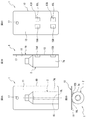
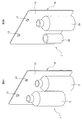
- 2A, 2B, 2C and 2D are explanatory views of an embodiment of a packaged product with a mount according to one aspect of the present invention, FIG. 2A is a front view thereof, FIG. 2B is a side view, and FIG. 2C is a side view.
- the rear view and FIG. 2D are plan views.
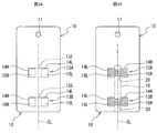
- 3A and 3B are explanatory views of an embodiment of a mount for a packaged product with a mount according to one aspect of the present invention, FIG. 3A is a front view in a state where an adhesive means is not arranged, and FIG. 3B is an adhesive means.
- FIG. 4 is a schematic view illustrating an embodiment of a packaged product manufacturing apparatus with a mount according to one aspect of the present invention.
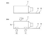
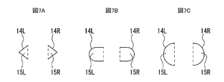
- 5A, 5B and 5C are schematic views illustrating a packaging process in the packaging product manufacturing apparatus of FIG. 6A and 6B are schematic views illustrating a sticking process in the packaging product manufacturing apparatus of FIG. 7A, 7B and 7C are visionary portions of the attachment portion and are views showing other examples of the cut shape of the slit.
- 8A and 8B are views showing another example of the final aspect of the packaged product with mount.
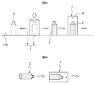
- 9A and 9B are diagrams showing other aspects of manufacturing a package with a mount.
- FIG. 10 is an enlarged view of a main part for explaining a modified example of the mount for a packaged product with a mount according to one aspect of the present invention.
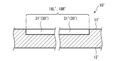
- FIG. 11 is a schematic view illustrating a first example of the cross section of the arrow XX portion of FIG.
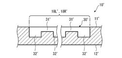
- FIG. 12 is a schematic view illustrating a second example of the cross section of the arrow XX portion of FIG.
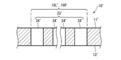
- FIG. 13 is a schematic view illustrating a third example of the cross section of the arrow XX portion of FIG.
- FIG. 14 is a schematic view illustrating a fourth example of the cross section of the arrow XX portion of FIG.
- FIG. 15 is a perspective view illustrating a modified example of the packaged product with a mount according to one aspect of the present invention.
- the packaged product 1 with a mount of the present embodiment includes a mount 10 and a package 2 attached to the front surface 11 of the mount 10.
- the mount 10 of this embodiment is made of cardboard.
- the mount 10 has a rectangular outer shape on the front surface 11 when viewed from the front, a circular hanging hole 17 is formed in the center of the upper portion, and the four corners are chamfered in an arc shape.
- Information such as an effect on the display and a description of the product to be packaged is printed on the front and back of the mount 10.
- the package 2 is an article 3 having a cylindrical outer shape portion 3 g wrapped with a shrink film 4 which is a synthetic resin film.
- the article 3 is, for example, a cosmetic product, in which the upper portion of the cylindrical outer shape portion 3g is formed in a truncated cone shape, and a screw cap is provided in the center of the upper portion.
- the attachment portions 13A and 13B are set on the mount 10, and the front surfaces 11 of the mount 10 are set on the attachment portions 13A and 13B.
- an adhesive means 20 such as a double-sided tape or a hot melt adhesive is supplied, and the package 2 is attached to the attachment portions 13A and 13B from the front surface 11 of the mount 10.
- the package 2 is attached with a position where the axis CL of the cylindrical outer shape portion 3 g is parallel to the long side or the short side (long side in this example) of the front surface 11. It is set to the planned position 16 (see the two-dot chain line portion in FIG. 3B).
- the position where the center of the rectangular front surface 11 and the axis CL coincide with each other is the scheduled attachment position 16.
- the attachment portions 13A and 13B are provided at a plurality of positions (two upper and lower positions in this example) along the axis CL of the cylindrical outer shape portion 3g with respect to the planned attachment position 16 of the package 2. Has been done.
- the mount 10 is set on the front surface 11 and has the attachment portions 13A and 13B to which the package 2 is attached, and a part of the attachment portions 13A and 13B.
- Slits 14L, 14R formed so as to form image parts 15L, 15R which can be bent or folded back toward the front surface 11 to project out, leaving 13s and limiting a part other than 13s.
- the slits 14L and 14R leave the central portion 13s of the attachment portions 13A and 13B as a part, and only the left and right side portions of the central portion 13s are bent or bent toward the front surface 11. It is formed so as to form two image forming portions 15L and 15R that can be folded back and overhanged.
- the sticking portions 13A and 13B are provided with two image portions 15L and 15R so as to be sandwiched from the left and right sides of the axis CL with the axis CL of the outer shape portion 3g as the center.
- the slits 14L and 14R are formed by cutting into a U shape in which the left and right side portions are [].
- the slits 14L and 14R are formed in advance when the mount 10 is punched.
- the broken line portion in FIG. 2C (in FIG. 3A, the portion of the rectangular broken line portion indicating the central portion 13s, the portion of the vertical line) is bent or folded back toward the front surface 11, and the drawing portions 15L and 15R are formed.
- the base end portion constituting the above is shown.
- the slits 14L and 14R of the present embodiment are formed when the front surface 11 is viewed from the front after the packaging body 2 is attached to the mount 10 as shown in FIGS. 1 and 2A to 2D.
- the image areas 15L and 15R are formed in a range hidden behind the package 2 and cannot be seen.
- the packaged product manufacturing apparatus 100 with a mount includes a conveyor 170 for transporting the article 3, the package 2, and the packaged product 1 with a mount.
- the conveyor 170 has a horizontal transport surface.
- the housing 110 is arranged at an appropriate position on the conveyor 170.
- the housing 110 is provided with a packaging device 120 at the upper part on the entry side, and a heating device 130 and a sticking device 140 are arranged in this order inside the housing 110.
- the packaging device 120 is equipped with a packaging means for packaging the article 3 with the shrink film 4.
- An adhesive supply device 160 and a mount supply device 150 are attached to the positions of the sticking device 140.
- the mount supply device 150 is arranged below the conveyor 170.
- the mount supply device 150 has a magazine that accommodates a plurality of mounts 10 (not shown below) and a carrier that arranges the mounts 10 accommodated in the magazines one by one at a predetermined position on the conveyor 170.
- the adhesive supply device 160 is configured to be able to supply the adhesive means 20 such as a hot melt adhesive to the mount 10 arranged at a predetermined position only in the range of the attachment portions 13A and 13B of the mount 10.
- the sticking device 140 has a manipulator configured so that the packaging body 2 in which the article 3 is wrapped in the shrink film 4 and the front surface 11 of the mount 10 face each other, and a pressing mechanism.
- the package 2 is placed in the lying position by the manipulator of the sticking device 140, and the article 3 is a shrink film as shown in FIG. 6A.
- the packaging body 2 packaged in 4 and the front surface 11 of the mount 10 face each other.
- the arrow indicated by the reference numeral R in FIG. 4 shows an image in which the package 2 is placed in a lying position and faces the front surface 11 of the mount 10 by a manipulator.
- the mount 10 when the mounts are arranged so as to face each other is in a state where the imaged portions 15L and 15R of the two attachment portions 13A and 13B are flat (face-to-face with the front surface 11).
- the adhesive supply device 160 applies the adhesive means 20 such as hot melt adhesive to the mount 10 arranged at a predetermined position only in the range of the attachment portions 13A and 13B of the mount 10. Supply (gluing process).
- the main body portion of the mount 10 remains flat by the pressing mechanism of the sticking device 140, and only the drawing portions 15L and 15R are attached to the outer shape of the article 3 to make it hot.
- the package 2 is attached to the upper and lower adhesive portions 13A and 13B by the adhesive means 20 which is a melt adhesive (adhesion step).
- the shrink film 4 is used to sufficiently secure the holding force (adhesive strength) of the attachment portions 13A and 13B between the article 3 and the mount 10 after packaging, and the other parts of the mount 10 are attached so as not to be attached. Therefore, it is possible to prevent deformation of the mount 10 due to sticking.
- the arrows indicated by reference numerals F3 in FIGS. 4 and 6B indicate an image in which the package 2 is pressed and held on the front surface 11 side of the mount 10 by a manipulator, and reference numerals F1 and F2 are shown in FIGS. 4 and 6B.
- the arrow indicated by is an image in which the upper and lower sticking portions 13A and 13B are pressed so as to follow the outer shape of the article 3 by the left and right image portions 15L and 15R, respectively.
- the package 2 in which the article 3 is wrapped in the shrink film 4 is attached to the planned attachment position 16 of the mount 10, and the package 1 with the mount is manufactured.
- the manufactured packaged product 1 with a mount is carried out to the next process downstream (arrow in OUT in FIG. 4).
- the mount 10 of the present embodiment As described above, according to the method of manufacturing the mount 10 for the package with the mount, the package 1 with the mount, the package manufacturing apparatus 100 with the mount, and the package 1 with the mount using the same, the mount 10 of the present embodiment.
- the article 3 is wrapped in a shrink film 4, and then the package 2 is attached by an adhesive means 20 such as a double-sided tape or a hot melt adhesive. Since it is attached to the mount 10, the shrink film 4 can be neatly attached to the outer shape of the article 3. Further, since it is easy to manage the attachment position of the package 2 with respect to the mount 10, the aesthetic appearance and productivity of the package 1 with the mount can be improved.
- a part 13s of the sticking portions 13A and 13B is left, and a part other than the part 13s is bent or folded back toward the front surface 11 to project. It is provided with slits 14L, 14R formed so as to form the components 15L, 15R.
- the attachment portions 13A and 13B to the mount 10 are attached to the cylindrical outer peripheral surface of the article 3 along only the drawing portions 15L and 15R, the areas of the attachment portions 13A and 13B are secured.
- the mount body can be left flat, the mount 10 does not warp and deform.
- the sticking portions 13A and 13B are provided with two image portions 15L and 15R so as to be sandwiched from the left and right sides of the axis CL with the axis CL of the outer shape portion 3g as the center. Therefore, it is suitable for ensuring sufficient holding power of the package 2 with respect to the mount 10.
- the imaged portions 15L and 15R are behind the packaging body 2. Since it is formed in a range hidden behind and invisible, it is suitable for improving the aesthetic appearance at the time of display while sufficiently securing the holding force of the package 2 with respect to the mount 10.
- the mount for the packaged product with the mount, the packaged product with the mount, and the packaging product manufacturing apparatus with the mount and the method for manufacturing the packaged product with the mount according to the present embodiment the synthetic resin film such as shrink film 4 or the like. It is possible to sufficiently secure the holding force (adhesive strength) of the attachment portions 13A and 13B between the article 3 and the mount 10 after packaging and prevent the mount 10 from being deformed by the attachment.
- the mount for the packaged product with the mount, the packaged product with the mount, the device for manufacturing the packaged product with the mount, and the method for manufacturing the packaged product with the mount according to the present invention are not limited to the above embodiments, and the method of manufacturing the packaged product with the mount is not limited to the above embodiment. Various modifications are possible without deviating from the purpose.
- the slits 14L and 14R may be cut into a triangular shape such as ⁇ > (FIG. 7A), or a U-shape. It may be cut into (Fig. 7B). Further, it may be cut into a semicircular shape (FIG. 7C), and the imaged portions 15L and 15R of the sticking portion can be configured to have a shape corresponding to each.
- the broken line portion of FIGS. 7A to 7C indicates a base end portion that is bent or folded back toward the front surface 11 to form the drawing portions 15L and 15R.
- the cutting step of the slits 14L and 14R has shown an example in which the slits 14L and 14R are formed in advance at the time of punching of the mount 10, but the present invention is not limited to this, and the packaging product manufacturing in which the packaging body 2 is attached to the mount 10 is not limited to this. It may be performed inside the machine of the device 100. Further, for example, in the above embodiment, regarding the method of adhering the package 2 to the hanging mount 10, in the gluing step, a hot melt adhesive is used as the adhesive means 20 inside the housing 110 of the package manufacturing apparatus 100. An example of supplying is shown, but the present invention is not limited to this.
- the front surface 11 of the mount 10 is set as one surface, and a hot melt adhesive is applied to the front surface 11 in advance, and the mounting position 16 of the mount 10 is planned to be attached.
- the hot melt adhesive may be melted by heat.
- the adhesive means 20 is not limited to the hot melt adhesive, and for example, double-sided tape may be used.
- the packaging mode of the article 3 is the packaging body 2 packaged with the shrink film 4, but the present invention is not limited to this, and a transparent or opaque synthetic resin film other than the shrink film is used. It may be present, or may be film packaging such as caramel packaging, three-way seal packaging, four-way seal packaging, and vertical pillow packaging. Further, it may be wrapped around the body.
- the outer shape of the mount 10 is rectangular is shown, but the outer shape of the mount 10 is not limited to the rectangle, and any outer shape can be set in addition to the rectangle.
- a free hole shape can be arbitrarily set in addition to the round hole.
- a plurality of packages 2 (two in FIG. 8A) can be attached to 10 at the same time (FIG. 8A), and the package 2 is not limited to the same shape, but has different shapes as shown in FIG. 8B, for example.
- a plurality of packages 2A and 2B can be attached to one mount 10.
- a plurality of hanging holes 17 (two in the examples of FIGS. 8A and 8B) may be provided.
- the shape of the hanging hole 17 is not limited to a circular shape, and may be an elliptical shape or a composite shape thereof in addition to a triangular hole and a rectangular hole.
- the article 3 in the upright posture is wrapped with the shrink film 4 to form the package 2, and then the package 2 is set in the lying posture, and the front of the mount 10 is set in the lying posture.
- An example of sticking to the sticking portions 13A and 13B facing the surface 11 is shown, but the present invention is not limited to this.
- the sticking portion is opposed to the front surface 11 of the mount 10 in the standing posture. It may be attached to 13A and 13B.
- the article 3 in the prone position is wrapped with a synthetic resin film such as a shrink film to form a package 2, and then the article 3 in the prone position faces the front surface 11 of the mount 10 in the prone position. It may be attached to the attachment portions 13A and 13B.
- the example of FIG. 9B shows a plan view, and is an example in which a horizontal pillow package is formed by a three-way sticker having a seal portion on the bottom surface, and the horizontal pillow package is attached to the mount 10 in a lying position. The seal on the bottom is shown as an image.
- FIGS. 10 to 14 [Modification example of mount]
- a modified example mount 10' (mount for packaging with a mount) will be described with reference to FIGS. 10 to 14.
- the mount 10'of this modification has the same configuration as the above-described configuration except for a special description, and the same reference numerals are given to these configurations, and detailed description thereof will be omitted.
- the mount 10'of this modified example in addition to the slits 14L'and 14R'formed so as to form the imaged portions 15L'and 15R', the imaged portions 15L'and 15R' A weak portion 30'(indicated by a broken line for convenience of illustration) is provided at the base end portions 18L'and 18R'.
- the slit 14R'on the right side and the base end portion 18R' are provided in a D shape, and if the D shape is subdivided into an I shape and a C shape, the base end portion 18R'is located at the I-shaped portion.
- the left slit 14L'and the proximal end portion 18L' show an example in which the slit 14R'and the proximal end portion 18R'are provided symmetrically with respect to the slit 14R'and the proximal end portion 18R'.
- the weak portion 30'exemplified here is provided in each of the proximal end portions 18L'and 18R'in the same configuration.
- the weak portion 30' is a structure (repulsive force suppressing structure) for suppressing the repulsive force due to the overhang of the imaged portions 15L'and 15R' bent or folded back toward the front surface 11' (one surface). is there.
- the base end portions 18L'and 18R' that function as the pivots of the imageable portions 15L'and 15R' that project from the main body portion 19'(mounting paper main body portion) that remains flat on the mount 10'and can be displaced.
- a weak portion 30' is provided which intentionally reduces the rigidity (so-called "stiffness") or strength.
- Various structures can be applied to the weak portion 30'as long as the repulsive force due to the overhang of the image forming portions 15L'and 15R'can be suppressed by the base end portions 18L'and 18R'.
- a perforated structure 33'(see FIG. 13) penetrating in the thickness direction of the mount 10' is also illustrated.
- the recess 31' is a recessed portion in the thickness direction of the mount 10'.
- the recess 31' can be formed linearly by a recessing process such as embossing, embossing, or deep digging on the base end portions 18L'and 18R'.
- FIG. 11 shows an example in which a linear recess 31'continuous over the entire area of the base end portions 18L'and 18R' is compacted from the front surface 11'.
- the recess 31' may be provided only in a part of the base end portions 18L'and 18R', may be provided in various forms such as a wavy line (curve shape) and a broken line shape, and the back surface 12' may be provided. It may be recessed from.
- the half-cut portion 32' is a portion cut in the thickness direction of the mount 10'without penetrating in the thickness direction.
- the half-cut portion 32' can be formed by so-called half-cut processing (also referred to as "half-cut processing").
- FIG. 12 shows an example in which the half-cut portion 32', which is provided intermittently at the base end portions 18L'and 18R'and has a broken line shape along a straight line, is cut from the front surface 11'.
- the half-cut portion 32' may be continuously provided over the entire area of the base end portions 18L'and 18R', may be provided along lines having various shapes such as straight lines and wavy lines, and may be provided on the back surface. It may be cut from 12'.
- the perforated structure 33' is a structure in which all cut portions 34'that penetrate the mount 10'in the thickness direction and are cut in the thickness direction are intermittently provided.
- the perforation structure 33' is formed by intermittently arranging all cut portions 34'formed by so-called total cutting (also referred to as "total cutting") in a perforated pattern (that is, perforation). It is possible.
- FIG. 13 illustrates a perforated structure 33'that is intermittently provided at the base end portions 18L'and 18R'and in which all the cut portions 34' in the shape of a broken line along a straight line are cut.
- all the cut portions 34' may be cut intermittently along lines having various shapes such as straight lines and wavy lines. If all the cut portions 33'are provided over the entire area of the base end portions 18L'and 18R', the imaging portions 15L'and 15R'will be cut out. Therefore, in the base end portions 18L'and 18R', the entire cut portion 33'is intermittent so that the portion where the imaging portion 15L', 15R'and the main body portion 19'(see FIG. 10) are continuously connected remains intermittently. Is arranged as a target.
- One of these recesses 31', half-cut portion 32', and perforated structure 33' may be applied to the weak portion 30'alone, or a plurality of them may be applied to the weak portion 30'in combination. May be good.
- the recess 31'and the half-cut portion 32' may be arranged in the weak portion 30'.
- a processing procedure for the weak portion 30' after processing to intermittently provide the half-cut portion 32'at the proximal end portions 18L'and 18R' from the front surface 11', the proximal end portion 18L', An example is given in which a process of providing a continuous recess 31'over the entire area of 18R' is performed from the front surface 11'.
- the notch of the half-cut portion 32' is intermittently arranged at a position deeper than the recess 31' recessed from the front surface 11'.
- the weak portion 30' can be provided on the mount 10'by utilizing an existing processing device or method for embossing the mount 10'.
- the base end portions 18L'and 18R' are compacted, the base end portions 18L'and 18R'are suppressed while suppressing a decrease in strength connecting the image forming portions 15L'and 15R'and the main body portion 19'. It is possible to reduce the stiffness in the direction intersecting the extending direction of ′. By suppressing the rigidity in the direction in which the main body portion 19'and the drawing portions 15L'and 15R' are connected in this way, the repulsive force of the drawing portions 15L'and 15R'can be suppressed.
- the degree of suppression of the repulsive force can be adjusted by the depth of cut of the half-cut portion 32'. Therefore, an appropriate repulsive force can be set according to the thickness and properties of the mount 10', and it is also possible to suppress fluctuations in the repulsive force that may fluctuate depending on the manufacturing environment such as temperature and humidity.
- the perforated structure 33' is applied to the weak portion 30', a simple manufacturing method is provided because the entire cut portion 34'that does not require delicate adjustment of the depth of cut is provided like the half cut portion 32'.
- a weak portion 30' can be provided. Further, by adjusting the pitch (density) of all the cut portions 34'in the perforated structure 33', the degree of suppression of the repulsive force can be adjusted.
- the overhanging image areas 15L'and 15R' As an example of the recess 31'and the half-cut portion 32', when the weak portion 30'is processed from the front surface 11'of the mount 10'as described above, the overhanging image areas 15L'and 15R' The compression deformation on the front surface 11'side at the base end portions 18L'and 18R' is relaxed. As a result, the repulsive force can be efficiently suppressed.
- the weak portion 30' that does not penetrate in the thickness direction of the mount 10'such as the recess 31'and the half-cut portion 32', when a fluid material such as a hot melt adhesive is used for the adhesive means 20
- a fluid material such as a hot melt adhesive
- the protrusion of the fluidized material from the front surface 11'to the back surface 12' through the weak portion 30' is structurally avoided.
- the handleability of the mount 10'in the manufacturing process can be ensured, which contributes to the improvement of the quality of the mount 10'.
- the weak portion 30'in which at least two of the recess 31', the half-cut portion 32', and the perforated structure 33' are provided side by side the repulsive force due to the overhang of the imaged portions 15L'and 15R'is surely suppressed. Therefore, the degree of suppression of the repulsive force can be adjusted according to the number of recesses 31', half-cut portions 32', and perforated structures 33'.
- a second weak portion may be provided in the drawing portions 15L'and 15R' along with the base end portions 18L'and 18R'.
- the packaged product 1 ′′ with a mount of this modification is provided with a packaged body 2 ′′ in which the article 3 ′′ is packaged by the shrink film 4 ′′ as a synthetic resin film.
- the article 3 ′′ is packaged by the heat-shrinked shrink film 4 ′′.
- the package 2 ′′ corresponds to the edge of the shrink film 4 ′′ before the heat shrinkage.
- a linear seal portion 4S "(so-called” seal wire ") extends at the portion.
- the seal portion 4S ′′ is also referred to as a “seal wire” and is a linear mark generated when the edges of the shrink film are sealed to each other.
- FIG. 15 illustrates the seal portion 4S ′′ of the three-way pillow packaging.
- the shrink film 4 ′′ that is heat-shrinked and wraps the article 3 ′′ has a property of being easily broken starting from the seal portion 4S ′′.
- the shrink film 4 ′′ that wraps the article 3 is It is easy to tear with the seal part 4S "as a starting point.
- the shrink film 4 "of the package 2" can be broken and the article 3 "can be taken out. Therefore, the package 1" with the mount can be taken out. Usability can be improved.
- the shrink film 4 "is broken if the shrink film 4" remains attached to the attachment portions 13A “and 13B" (mounting sheet 10 ") via the adhesive means 20", the packaged product with the backing sheet 1 It is easy to dispose of the mount 10 ′′ and the shrink film 4 ′′ other than the article 3 ′′ together. From this point as well, it contributes to improving the usability of the packaged product 1 "with mount.
- the mount is not limited to the cardboard described above, and various materials can be used. From the viewpoint of ensuring printability and rigidity, it is preferable to use white paperboard as the mount. Among these white paperboards, it is more preferable to use coated balls, uncoated balls, high-grade paperboards, special paperboards, cup base papers and the like.
- the basis weight of the mount is 400 to 500 [g / m 2 ] from the viewpoint of ensuring the workability of the mount, suppressing the warp of the mount, and appropriately setting the repulsive force of the imaged portion.
- the mount is not limited to paper, and a resin or rubber mount may be used. When a mount that is not made of paper is used, it is preferable that an adhesive means suitable for the material is appropriately used.
- the hot melt adhesive used as the adhesive for the mount various known systems such as EVA type, olefin type, rubber type, polyamide type and polyester type can be appropriately used. Of these, a rubber-based hot melt adhesive is preferable from the viewpoint of ensuring durability, and an olefin-based hot melt adhesive is preferable from the viewpoint of ensuring compatibility with a polypropylene-based shrink film.
- a two-component curing type hot melt agent can also be used.
- the two-component curing type hot melt agents it is preferable to use a reaction type containing urethane resin as a main component from the viewpoint of ensuring high heat resistance and adhesiveness.
- a reaction-type hot melt agent when cooled, it solidifies in a form that leaves isocyanate groups, and after cooling, the water in the air reacts with the isocyanate groups to advance the polymer, resulting in higher heat resistance. Adhesiveness is obtained.
- shrink film various known films such as polyethylene terephthalate film, polyethylene film, polypropylene film and the like can be appropriately used. From the viewpoint of suppressing the occurrence of wrinkles during heat shrinkage (so-called “shrink”) and from the viewpoint of heat shrinkage at a low temperature, it is particularly preferable to use a polypropylene-based shrink film having a main composition of polyolefin.
Landscapes
- Engineering & Computer Science (AREA)
- Mechanical Engineering (AREA)
- Packages (AREA)
Abstract
合成樹脂フィルム(4)で包装後の物品(3)と台紙(10)との貼着部の保持力(接着強度)を十分に確保するとともに、貼着による台紙(10)の変形を防止するために、この台紙(10)は、おもて面(11)に設定されて包装体(2)が貼着される貼着部(13A、13B)と、貼着部(13A、13B)の一部(13s)を残してその一部(13s)以外の部分を、おもて面(11)の側に張り出し可能な画成部分(15L、15R)として構成するように形成されたスリット(14L、14R)と、を備える。
Description
本発明は、合成樹脂フィルムで包装された状態の商品等の物品が台紙に付設された包装態様に好適な包装技術に関する。
商品等の物品を透明ないし不透明な合成樹脂フィルムで覆うことでディスプレイ可能にパッケージする包装態様として、ブリスターパックや、台紙付き包装品が知られている。
例えば台紙付き包装品は、特許文献1に開示される筒状フィルム付き台紙のように、透明ないし不透明な合成樹脂フィルムとして、筒状のシュリンクフィルムが台紙に予め貼着されている。この種の筒状フィルム付き台紙を使用する際は、まず、筒状のシュリンクフィルム内に物品を入れて、その後に、筒状のシュリンクフィルムを熱収縮させて物品を包装して台紙付き包装品とする。
例えば台紙付き包装品は、特許文献1に開示される筒状フィルム付き台紙のように、透明ないし不透明な合成樹脂フィルムとして、筒状のシュリンクフィルムが台紙に予め貼着されている。この種の筒状フィルム付き台紙を使用する際は、まず、筒状のシュリンクフィルム内に物品を入れて、その後に、筒状のシュリンクフィルムを熱収縮させて物品を包装して台紙付き包装品とする。
しかし、この種の筒状フィルム付き台紙であると、筒状のシュリンクフィルム内に物品を入れる装入位置を、予定した配置位置に保持しつつシュリンクフィルムを熱収縮させることが難しく、この装入作業および熱収縮作業が、台紙付き包装品の生産性をより向上させる上での問題になっている。
また、物品の外形形態によっては、筒状のシュリンクフィルムが台紙に予め貼着されていると、物品の外形に添わせるように綺麗に筒状のシュリンクフィルムを熱収縮させることが難しく、台紙付き包装品の美観が低下するという問題がある。
また、物品の外形形態によっては、筒状のシュリンクフィルムが台紙に予め貼着されていると、物品の外形に添わせるように綺麗に筒状のシュリンクフィルムを熱収縮させることが難しく、台紙付き包装品の美観が低下するという問題がある。
これに対し、台紙に筒状フィルムを予め貼着するのではなく、まず、物品をシュリンクフィルム等の合成樹脂フィルムで包装した包装体とし、次いで、その包装体を、両面テープやホットメルト接着剤等の接着手段で台紙に貼着すれば、物品の外形に綺麗に合成樹脂フィルムを添わせることができる上、その後の台紙に対する包装体の貼着位置の管理も容易なので、台紙付き包装品の美観および生産性を向上させることができる。
一方、例えば物品の外形が円筒体であると、合成樹脂フィルムで包装後の物品と台紙との貼着部の面積が狭く(細い帯状に)なる。そのため、台紙に対する包装体の保持力が充分に確保されないおそれがある。また、物品の円筒状外周面に台紙との貼着部を沿わせて貼着すると、貼着部の面積は確保できるものの、台紙が反って変形してしまうという問題がある。
一方、例えば物品の外形が円筒体であると、合成樹脂フィルムで包装後の物品と台紙との貼着部の面積が狭く(細い帯状に)なる。そのため、台紙に対する包装体の保持力が充分に確保されないおそれがある。また、物品の円筒状外周面に台紙との貼着部を沿わせて貼着すると、貼着部の面積は確保できるものの、台紙が反って変形してしまうという問題がある。
そこで、本発明は、このような問題点に着目してなされたものであって、合成樹脂フィルムで包装後の物品と台紙との貼着部の保持力(接着強度)を十分に確保するとともに、貼着による台紙の変形を防止し得る、台紙付き包装品用台紙、台紙付き包装品、並びに、台紙付き包装品製造装置および台紙付き包装品の製造方法を提供することを課題とする。
上記課題を解決するために、本発明の一態様に係る台紙付き包装品用台紙は、物品が合成樹脂フィルムで包装された包装体を貼着して台紙付き包装品とするための台紙であって、一の面に設定されて前記包装体が貼着される貼着部と、該貼着部の一部を残してその一部以外の部分を限って前記一の面の側に張り出し可能な画成部分を構成するように形成されたスリットと、を備えることを特徴とする。
また、本発明の一態様に係る台紙付き包装品は、一の面に貼着部が設定された台紙と、該台紙の貼着部に貼着されて合成樹脂フィルムで物品を包装してなる包装体と、を備え、前記台紙として、本発明の一態様に係る台紙付き包装品用台紙が用いられていることを特徴とする。
また、本発明の一態様に係る台紙付き包装品の製造方法は、本発明の一態様に係る台紙付き包装品を製造する方法であって、前記物品を前記合成樹脂フィルムで包装して包装体とする包装工程と、前記台紙の前記一の面と前記包装体とを対向させるとともに前記物品の外形に前記画成部分を添わせて、両面テープまたはホットメルト接着剤等の接着手段によって前記貼着部に前記包装体を貼着する貼着工程と、を含むことを特徴とする。
また、本発明の一態様に係る台紙付き包装品製造装置は、本発明の一態様に係る台紙付き包装品を製造する台紙付き包装品製造装置であって、前記物品を前記合成樹脂フィルムで包装する包装装置と、両面テープまたはホットメルト接着剤等の接着手段を前記台紙の前記貼着部に供給する接着手段供給装置と、前記台紙の前記一の面と前記包装体とを対向させるとともに前記一の面とは反対の側から前記画成部分を押圧することで前記物品の外形に前記画成部分を添わせて前記接着手段が供給された前記貼着部に前記包装体を貼着する貼着装置と、を備えることを特徴とする。
本発明によれば、物品の外形に対して台紙の貼着部に設けられた画成部分のみを添わせて、台紙本体部分を平らなままで、合成樹脂フィルムで包装後の物品を貼着部に貼着できる。そのため、包装後の物品と台紙との貼着部の保持力(接着強度)を十分に確保するとともに、貼着による台紙の変形を防止できる。
以下、本発明の一実施形態について、図面を適宜参照しつつ説明する。なお、図面は模式的なものである。そのため、厚みと平面寸法との関係、比率等は現実のものとは異なることに留意すべきであり、図面相互間においても互いの寸法の関係や比率が異なる部分が含まれている。
また、以下に示す実施形態は、本発明の技術的思想を具体化するための装置や方法を例示するものであって、本発明の技術的思想は、構成部品の材質、形状、構造、配置等を下記の実施形態に特定するものではない。
また、以下に示す実施形態は、本発明の技術的思想を具体化するための装置や方法を例示するものであって、本発明の技術的思想は、構成部品の材質、形状、構造、配置等を下記の実施形態に特定するものではない。
[台紙付き包装品]
図1に斜視図を示すように、本実施形態の台紙付き包装品1は、台紙10と、台紙10のおもて面11に貼着される包装体2と、を備える。本実施形態の台紙10は、ボール紙製である。台紙10は、正面視において、おもて面11の外形が矩形状をなし、上部中央に円形の掛用穴17が形成され、四隅は円弧状に面取りされている。台紙10の表裏には、ディスプレイ上の演出や、包装される商品説明等の情報が印刷される。
包装体2は、円筒状の外形形状部3gを有する物品3が、合成樹脂フィルムであるシュリンクフィルム4によって包装されたものである。物品3は、例えば化粧品であり、円筒状の外形形状部3gの上部が円錐台状に形成され、その上部中央にスクリューキャップが設けられている。
図1に斜視図を示すように、本実施形態の台紙付き包装品1は、台紙10と、台紙10のおもて面11に貼着される包装体2と、を備える。本実施形態の台紙10は、ボール紙製である。台紙10は、正面視において、おもて面11の外形が矩形状をなし、上部中央に円形の掛用穴17が形成され、四隅は円弧状に面取りされている。台紙10の表裏には、ディスプレイ上の演出や、包装される商品説明等の情報が印刷される。
包装体2は、円筒状の外形形状部3gを有する物品3が、合成樹脂フィルムであるシュリンクフィルム4によって包装されたものである。物品3は、例えば化粧品であり、円筒状の外形形状部3gの上部が円錐台状に形成され、その上部中央にスクリューキャップが設けられている。
図2A~図2Dならびに図3Aおよび図3Bに示すように、台紙10には、貼着部13A、13Bが設定されており、貼着部13A、13Bには、台紙10のおもて面11から、両面テープまたはホットメルト接着剤等の接着手段20が供給され(図3B参照)、包装体2は、台紙10のおもて面11から貼着部13A、13Bに貼着される。
包装体2は、図2Aに示すように、円筒状の外形形状部3gの軸線CLが、おもて面11の長辺または短辺(この例では長辺)と平行となる位置を貼着予定位置16(図3Bの二点鎖線部分参照)とされている。
この例では、矩形状のおもて面11の中心と軸線CLとが一致する位置が貼着予定位置16になっている。貼着部13A、13Bは、包装体2の貼着予定位置16に対し、円筒状の外形形状部3gの軸線CLに沿って複数の位置(この例では上下の二箇所)に離隔して設けられている。
包装体2は、図2Aに示すように、円筒状の外形形状部3gの軸線CLが、おもて面11の長辺または短辺(この例では長辺)と平行となる位置を貼着予定位置16(図3Bの二点鎖線部分参照)とされている。
この例では、矩形状のおもて面11の中心と軸線CLとが一致する位置が貼着予定位置16になっている。貼着部13A、13Bは、包装体2の貼着予定位置16に対し、円筒状の外形形状部3gの軸線CLに沿って複数の位置(この例では上下の二箇所)に離隔して設けられている。
図3Aおよび図3Bに台紙を示すように、台紙10は、おもて面11に設定されて包装体2が貼着される貼着部13A、13Bと、貼着部13A、13Bの一部13sを残し、その一部13s以外の部分を限って、おもて面11の側に曲げまたは折り返して張り出し可能な画成部分15L、15Rとして構成するように形成されたスリット14L、14Rと、を備える。
この例では、スリット14L、14Rは、貼着部13A、13Bの中央部分13sを一部として残しており、この中央部分13sの左右両側の部分のみを、おもて面11の側に曲げまたは折り返して張り出し可能な二つの画成部分15L、15Rを構成するように形成されている。これにより、各貼着部13A、13Bは、外形形状部3gの軸線CLを中心にして、軸線CLの左右から挟み込むように二つの画成部分15L、15Rが設けられる。
この例では、スリット14L、14Rは、貼着部13A、13Bの中央部分13sを一部として残しており、この中央部分13sの左右両側の部分のみを、おもて面11の側に曲げまたは折り返して張り出し可能な二つの画成部分15L、15Rを構成するように形成されている。これにより、各貼着部13A、13Bは、外形形状部3gの軸線CLを中心にして、軸線CLの左右から挟み込むように二つの画成部分15L、15Rが設けられる。
また、この例では、スリット14L、14Rは、左右両側の部分が[ ]となるコの字形状に切断して形成されている。スリット14L、14Rは、台紙10の打ち抜き加工時に予め形成される。なお、図2Cの破線部分(図3Aでは、中央部分13sを示す矩形の破線部分のうち縦の線の部分)は、おもて面11の側に曲げまたは折り返しされて画成部分15L、15Rを構成する基端部分を示している。
特に、本実施形態のスリット14L、14Rは、図1および図2A~図2Dに示すように、包装体2を台紙10に貼着した後に、おもて面11を正面から見たときに、画成部分15L、15Rが、包装体2の陰に隠れて視認できない範囲に形成されている。
特に、本実施形態のスリット14L、14Rは、図1および図2A~図2Dに示すように、包装体2を台紙10に貼着した後に、おもて面11を正面から見たときに、画成部分15L、15Rが、包装体2の陰に隠れて視認できない範囲に形成されている。
[台紙付き包装品製造装置]
次に、台紙付き包装品製造装置100について説明する。
図4に示すように、台紙付き包装品製造装置100は、物品3、包装体2および台紙付き包装品1を搬送するためのコンベア170を備える。コンベア170は、搬送面が水平に設置されている。コンベア170の適所に、筐体110が配置されている。
筐体110には、入側上部に包装装置120が設けられ、筐体110の内部に加熱装置130および貼着装置140が順に配置されている。包装装置120には、物品3をシュリンクフィルム4で包装するための包装手段が装備されている。貼着装置140の位置には、接着剤供給装置160および台紙供給装置150が付設されている。台紙供給装置150は、コンベア170の下方に配置されている。
次に、台紙付き包装品製造装置100について説明する。
図4に示すように、台紙付き包装品製造装置100は、物品3、包装体2および台紙付き包装品1を搬送するためのコンベア170を備える。コンベア170は、搬送面が水平に設置されている。コンベア170の適所に、筐体110が配置されている。
筐体110には、入側上部に包装装置120が設けられ、筐体110の内部に加熱装置130および貼着装置140が順に配置されている。包装装置120には、物品3をシュリンクフィルム4で包装するための包装手段が装備されている。貼着装置140の位置には、接着剤供給装置160および台紙供給装置150が付設されている。台紙供給装置150は、コンベア170の下方に配置されている。
台紙供給装置150は、以下不図示の、複数の台紙10を収容するマガジンと、マガジンに収容された台紙10を一枚ずつコンベア170の所定位置に配置するキャリアとを有する。接着剤供給装置160は、所定位置に配置された台紙10に対し、ホットメルト接着剤等の接着手段20を、台紙10の貼着部13A、13Bの範囲のみに供給可能に構成されている。
貼着装置140は、物品3がシュリンクフィルム4で包装された包装体2と、台紙10のおもて面11とを対向させるように構成されたマニピュレータと、押圧機構とを有し、押圧機構によって、おもて面11とは反対の裏面12側から、上下の貼着部13A、13Bそれぞれの左右の画成部分15L、15Rを物品3の外形に添わせるように押圧することで、物品3の外形に画成部分15L、15Rのみを添わせて、接着手段が供給された貼着部13A、13Bに包装体2を貼着可能になっている。
貼着装置140は、物品3がシュリンクフィルム4で包装された包装体2と、台紙10のおもて面11とを対向させるように構成されたマニピュレータと、押圧機構とを有し、押圧機構によって、おもて面11とは反対の裏面12側から、上下の貼着部13A、13Bそれぞれの左右の画成部分15L、15Rを物品3の外形に添わせるように押圧することで、物品3の外形に画成部分15L、15Rのみを添わせて、接着手段が供給された貼着部13A、13Bに包装体2を貼着可能になっている。
[台紙付き包装品の製造方法]
次に、上記台紙付き包装品製造装置100により、台紙付き包装品1を製造する方法について説明する。
台紙付き包装品1を製造する際は、まず、図4に示す台紙付き包装品製造装置100のコンベア170に対し、上流側(図4中、INの矢印)から起立姿勢の物品3を順次に搬送する。物品3が包装装置120に対する所定位置Sに位置したら、図5Aに示すように、物品3の上部から円筒状のシュリンクフィルム4を落下させ、図5Bに示すように、物品3の外周をシュリンクフィルム4で覆う状態とする。
次に、上記台紙付き包装品製造装置100により、台紙付き包装品1を製造する方法について説明する。
台紙付き包装品1を製造する際は、まず、図4に示す台紙付き包装品製造装置100のコンベア170に対し、上流側(図4中、INの矢印)から起立姿勢の物品3を順次に搬送する。物品3が包装装置120に対する所定位置Sに位置したら、図5Aに示すように、物品3の上部から円筒状のシュリンクフィルム4を落下させ、図5Bに示すように、物品3の外周をシュリンクフィルム4で覆う状態とする。
次いで、外周がシュリンクフィルム4で覆われた状態の物品3を、コンベア170の搬送によって加熱装置130に対する所定位置に位置させたら、図5Cに示すように、物品3の周囲から熱を加えて、物品3をシュリンクフィルム4で包装して包装体2とする(包装工程)。なお、図5Cで符号Wを付した矢印は、熱風によってシュリンクフィルム4を熱収縮させているイメージを示している。
次いで、包装体2をコンベア170の搬送によって貼着装置140に対する所定位置に位置させたら、貼着装置140のマニピュレータにより包装体2を倒伏姿勢とし、図6Aに示すように、物品3がシュリンクフィルム4に包装された包装体2と、台紙10のおもて面11とを対向させる。なお、図4に符号Rで示す矢印は、マニピュレータによって包装体2を倒伏姿勢として台紙10のおもて面11に対向させているイメージを示している。ここで、この対向配置させるときの台紙10は、二つの貼着部13A、13Bそれぞれの画成部分15L、15Rが平らなまま(おもて面11と面一)の状態である。
その後または対向配置させる前に、接着剤供給装置160により、所定位置に配置された台紙10に対し、ホットメルト接着剤等の接着手段20を、台紙10の貼着部13A、13Bの範囲のみに供給する(糊打ち工程)。次いで、図6Bに示す対向配置させた状態で、貼着装置140の押圧機構により、台紙10の本体部分は平らなままで、物品3の外形に画成部分15L、15Rのみを添わせ、ホットメルト接着剤である接着手段20によって上下の貼着部13A、13Bに包装体2を貼着する(貼着工程)。
これにより、物品3の外形に対して台紙10の上下の貼着部13A、13Bに設けられた各画成部分15L、15Rのみを添わせて、シュリンクフィルム4で包装後の物品3を貼着部13A、13Bに貼着できる。
そのため、シュリンクフィルム4で包装後の物品3と台紙10との貼着部13A、13Bの保持力(接着強度)を十分に確保するとともに、台紙10の他の部分は添わせないように貼着できるので、貼着による台紙10の変形を防止できる。
そのため、シュリンクフィルム4で包装後の物品3と台紙10との貼着部13A、13Bの保持力(接着強度)を十分に確保するとともに、台紙10の他の部分は添わせないように貼着できるので、貼着による台紙10の変形を防止できる。
なお、図4および図6Bに符号F3で示す矢印は、マニピュレータによって包装体2を台紙10のおもて面11側に押圧保持しているイメージを示し、図4および図6Bに符号F1、F2で示す矢印は、押圧機構により、上下の貼着部13A、13Bそれぞれの左右の画成部分15L、15Rを物品3の外形に添わせるように押圧しているイメージを示している。
これにより、物品3がシュリンクフィルム4で包装された包装体2が台紙10の貼着予定位置16に貼着されて台紙付き包装品1が製造される。製造された台紙付き包装品1は、下流(図4中、OUTの矢印)の次工程に向けて搬出される。
これにより、物品3がシュリンクフィルム4で包装された包装体2が台紙10の貼着予定位置16に貼着されて台紙付き包装品1が製造される。製造された台紙付き包装品1は、下流(図4中、OUTの矢印)の次工程に向けて搬出される。
このように、本実施形態の台紙付き包装品用台紙10、台紙付き包装品1、並びに、台紙付き包装品製造装置100およびこれを用いた台紙付き包装品1の製造方法によれば、台紙10に筒状フィルムを予め貼着するのではなく、まず、物品3をシュリンクフィルム4で包装した包装体2とし、次いで、その包装体2を、両面テープやホットメルト接着剤等の接着手段20で台紙10に貼着しているので、物品3の外形に綺麗にシュリンクフィルム4を添わせることができる。さらに、台紙10に対する包装体2の貼着位置の管理も容易なので、台紙付き包装品1の美観および生産性を向上させることができる。
そして、本実施形態の台紙10であれば、貼着部13A、13Bの一部13sを残してその一部13s以外の部分を、おもて面11の側に曲げまたは折り返して張り出し可能な画成部分15L、15Rとして構成するように形成されたスリット14L、14Rと、を備えている。
これにより、物品3の外形が円筒体であっても、シュリンクフィルム4で包装後の物品3と台紙10との貼着部13A、13Bの面積を必要十分に広く確保できる。そのため、台紙10に対する包装体2の保持力が充分に確保される。
また、物品3の円筒状外周面に台紙10との貼着部13A、13Bを画成部分15L、15Rのみを沿わせて貼着しているので、貼着部13A、13Bの面積を確保しつつ、台紙本体は平らなままとすることができるため、台紙10が反って変形してしまうこともない。
これにより、物品3の外形が円筒体であっても、シュリンクフィルム4で包装後の物品3と台紙10との貼着部13A、13Bの面積を必要十分に広く確保できる。そのため、台紙10に対する包装体2の保持力が充分に確保される。
また、物品3の円筒状外周面に台紙10との貼着部13A、13Bを画成部分15L、15Rのみを沿わせて貼着しているので、貼着部13A、13Bの面積を確保しつつ、台紙本体は平らなままとすることができるため、台紙10が反って変形してしまうこともない。
特に、本実施形態であれば、各貼着部13A、13Bは、外形形状部3gの軸線CLを中心にして、軸線CLの左右から挟み込むように二つの画成部分15L、15Rが設けられているので、台紙10に対する包装体2の保持力が充分に確保する上で好適である。
また、本実施形態のスリット14L、14Rは、包装体2を台紙10に貼着した後に、おもて面11を正面から見たときに、画成部分15L、15Rが、包装体2の陰に隠れて視認できない範囲に形成されているので、台紙10に対する包装体2の保持力が充分に確保しつつも、ディスプレイ時の美観をより良くする上で好適である。
また、本実施形態のスリット14L、14Rは、包装体2を台紙10に貼着した後に、おもて面11を正面から見たときに、画成部分15L、15Rが、包装体2の陰に隠れて視認できない範囲に形成されているので、台紙10に対する包装体2の保持力が充分に確保しつつも、ディスプレイ時の美観をより良くする上で好適である。
以上説明したように、本実施形態の台紙付き包装品用台紙、台紙付き包装品、並びに、台紙付き包装品製造装置および台紙付き包装品の製造方法によれば、シュリンクフィルム4等の合成樹脂フィルムで包装後の物品3と台紙10との貼着部13A、13Bの保持力(接着強度)を十分に確保するとともに、貼着による台紙10の変形を防止できる。
なお、本発明に係る台紙付き包装品用台紙、台紙付き包装品、並びに、台紙付き包装品製造装置および台紙付き包装品の製造方法は、上記実施形態に限定されるものではなく、本発明の趣旨を逸脱しなければ種々の変形が可能である。
なお、本発明に係る台紙付き包装品用台紙、台紙付き包装品、並びに、台紙付き包装品製造装置および台紙付き包装品の製造方法は、上記実施形態に限定されるものではなく、本発明の趣旨を逸脱しなければ種々の変形が可能である。
例えば、上記実施形態では、貼着部の画成部分を、スリット14L、14Rの切断形状が、[ ]となるコの字形状に切断して形成した例を示したが、これに限定されるものではない。
例えば、図7A~図7Cに他の例を示すように、スリット14L、14Rの切断形状は、例えば、<>となる三角形状に切断してもよいし(図7A)、また、U字形状に切断してもよい(図7B)。また、半円形状に切断してもよく(図7C)、貼着部の画成部分15L、15Rをそれぞれに応じた形状になるように構成することができる。なお、図7A~図7Cの破線部分は、おもて面11の側に曲げまたは折り返しされて画成部分15L、15Rを構成する基端部分を示している。
例えば、図7A~図7Cに他の例を示すように、スリット14L、14Rの切断形状は、例えば、<>となる三角形状に切断してもよいし(図7A)、また、U字形状に切断してもよい(図7B)。また、半円形状に切断してもよく(図7C)、貼着部の画成部分15L、15Rをそれぞれに応じた形状になるように構成することができる。なお、図7A~図7Cの破線部分は、おもて面11の側に曲げまたは折り返しされて画成部分15L、15Rを構成する基端部分を示している。
また、例えば上記実施形態では、スリット14L、14Rの切断工程は、台紙10の打ち抜き加工時に予め形成される例を示したが、これに限らず、包装体2を台紙10に貼付する包装品製造装置100の機械内部で行ってもよい。
また、例えば上記実施形態では、吊り下げ用の台紙10への包装体2の接着方法について、糊打ち工程は、包装品製造装置100の筐体110内部で、接着手段20としてホットメルト接着剤を供給する例を示したが、これに限定されるものではない。
例えば、台紙10への印刷工程時に、台紙10のおもて面11を一の面とし、おもて面11にホットメルト接着剤を予め塗布しておき、その台紙10の貼着予定位置16に包装体2を配置した後に、ホットメルト接着剤を熱で溶かすようにしてもよい。また、接着手段20も、ホットメルト接着剤に限らず、例えば両面テープを用いてもよい。
また、例えば上記実施形態では、吊り下げ用の台紙10への包装体2の接着方法について、糊打ち工程は、包装品製造装置100の筐体110内部で、接着手段20としてホットメルト接着剤を供給する例を示したが、これに限定されるものではない。
例えば、台紙10への印刷工程時に、台紙10のおもて面11を一の面とし、おもて面11にホットメルト接着剤を予め塗布しておき、その台紙10の貼着予定位置16に包装体2を配置した後に、ホットメルト接着剤を熱で溶かすようにしてもよい。また、接着手段20も、ホットメルト接着剤に限らず、例えば両面テープを用いてもよい。
また、例えば上記実施形態では、物品3の包装態様がシュリンクフィルム4で包装された包装体2とする例を示したが、これに限らず、シュリンクフィルム以外の、透明または不透明な合成樹脂フィルムであってもよいし、例えば、キャラメル包装、三方シール包装、四方シール包装、縦ピロー包装等のフィルム包装であってもよい。また、胴巻き包装であってもよい。
また、例えば上記実施形態では、台紙10の外形形状が矩形の例を示したが、これに限らず、台紙10の外形形状は、矩形の他、自由な外形形状を設定できる。また、掛用穴17の形状についても、丸穴の他、自由な穴形状を任意に設定できる。
また、例えば上記実施形態では、台紙10の外形形状が矩形の例を示したが、これに限らず、台紙10の外形形状は、矩形の他、自由な外形形状を設定できる。また、掛用穴17の形状についても、丸穴の他、自由な穴形状を任意に設定できる。
また、台紙付き包装品1の最終態様についても、上記実施形態に示したように、単品の物品3を張り付けた態様は勿論、図8Aおよび図8Bに他の例を示すように、一つの台紙10に複数本(図8Aでは二本)の包装体2を同時に張り付けることができるし(図8A)、また、同一形状の包装体2に限らず、例えば図8Bに示すように、異なる形状の複数の包装体2A、2Bを一つの台紙10に張り付けることができる。
また、複数(図8Aおよび図8Bの例では二つ)の掛用穴17を設けてもよい。また、掛用穴17の形状も円形に限定されず、三角形状穴、矩形形状穴の他、楕円形状やこれらの複合形状としてもよい。
また、複数(図8Aおよび図8Bの例では二つ)の掛用穴17を設けてもよい。また、掛用穴17の形状も円形に限定されず、三角形状穴、矩形形状穴の他、楕円形状やこれらの複合形状としてもよい。
また、上記実施形態では、台紙付き包装品1を製造するに際し、起立姿勢の物品3をシュリンクフィルム4で包装して包装体2とした後に倒伏姿勢とし、その倒伏姿勢で台紙10のおもて面11に対向させて貼着部13A、13Bに貼着した例を示したがこれに限定されない。
例えば、図9Aに示すように、起立姿勢の物品3をシュリンクフィルム4で包装して包装体2とした後、その起立姿勢のままで台紙10のおもて面11に対向させて貼着部13A、13Bに貼着してもよい。
例えば、図9Aに示すように、起立姿勢の物品3をシュリンクフィルム4で包装して包装体2とした後、その起立姿勢のままで台紙10のおもて面11に対向させて貼着部13A、13Bに貼着してもよい。
また、図9Bに示すように、倒伏姿勢の物品3をシュリンクフィルム等の合成樹脂フィルムで包装して包装体2とした後、その倒伏姿勢のままで台紙10のおもて面11に対向させて貼着部13A、13Bに貼着してもよい。
図9Bの例は平面視を示しており、底面にシール部を有する三方シールにより横ピロー包装品とし、この横ピロー包装品を倒伏姿勢のままで台紙10に貼着する例である。なお、底面のシール部はイメージとして示している。
図9Bの例は平面視を示しており、底面にシール部を有する三方シールにより横ピロー包装品とし、この横ピロー包装品を倒伏姿勢のままで台紙10に貼着する例である。なお、底面のシール部はイメージとして示している。
[台紙の変形例]
以下、図10~図14を参照して、変形例の台紙10′(台紙付き包装品用台紙)を説明する。
本変形例の台紙10′は、特に説明する点を除いて上述の構成と同様の構成であり、これらの構成については同様の符号を付して詳細な説明を省略する。
以下、図10~図14を参照して、変形例の台紙10′(台紙付き包装品用台紙)を説明する。
本変形例の台紙10′は、特に説明する点を除いて上述の構成と同様の構成であり、これらの構成については同様の符号を付して詳細な説明を省略する。
<構成>
図10に示すように、本変形例の台紙10′には、画成部分15L′、15R′を構成するように形成されたスリット14L′、14R′のほか、画成部分15L′、15R′の基端部分18L′、18R′に弱部30′(図示の便宜上破線で示す)が設けられている。
図10では、右側のスリット14R′および基端部分18R′がD字形状に設けられ、D字をI字形状およびC字形状に細別して捉えれば、I字形状の箇所に基端部分18R′が配置され、C字形状の箇所にスリット14R′が配置された例を示す。左側のスリット14L′および基端部分18L′は、スリット14R′および基端部分18R′に対して左右対称に設けられた例を示す。なお、ここで例示する弱部30′は、基端部分18L′、18R′のそれぞれに同様の構成で設けられている。
図10に示すように、本変形例の台紙10′には、画成部分15L′、15R′を構成するように形成されたスリット14L′、14R′のほか、画成部分15L′、15R′の基端部分18L′、18R′に弱部30′(図示の便宜上破線で示す)が設けられている。
図10では、右側のスリット14R′および基端部分18R′がD字形状に設けられ、D字をI字形状およびC字形状に細別して捉えれば、I字形状の箇所に基端部分18R′が配置され、C字形状の箇所にスリット14R′が配置された例を示す。左側のスリット14L′および基端部分18L′は、スリット14R′および基端部分18R′に対して左右対称に設けられた例を示す。なお、ここで例示する弱部30′は、基端部分18L′、18R′のそれぞれに同様の構成で設けられている。
弱部30′は、おもて面11′(一の面)の側に曲げまたは折り返された画成部分15L′、15R′の張り出しによる反発力を抑えるための構造(反発力抑制構造)である。
言い換えれば、台紙10′において平らなままの本体部分19′(台紙本体部分)に対して張り出して変位自在な画成部分15L′、15R′の枢軸として機能する基端部分18L′、18R′に、剛性(いわゆる「こわさ」)あるいは強度をあえて低下させる弱部30′が設けられている。
言い換えれば、台紙10′において平らなままの本体部分19′(台紙本体部分)に対して張り出して変位自在な画成部分15L′、15R′の枢軸として機能する基端部分18L′、18R′に、剛性(いわゆる「こわさ」)あるいは強度をあえて低下させる弱部30′が設けられている。
画成部分15L′、15R′は、スリット14L′、14R′および基端部分18L′、18R′で囲繞されており、張り出された姿勢の保持が弱部30′による反発力の抑制によって図られる。弱部30′には、画成部分15L′、15R′の張り出しによる反発力を基端部分18L′、18R′で抑えられるのであれば、さまざまな構造を適用することができる。
下記の説明では、弱部30′に適用しうる構造として、台紙10′の厚み方向に貫通していない凹部31′(図11参照)およびハーフカット部32′(図12参照)を例示し、台紙10′の厚み方向に貫通した目打構造33′(図13参照)も例示する。
下記の説明では、弱部30′に適用しうる構造として、台紙10′の厚み方向に貫通していない凹部31′(図11参照)およびハーフカット部32′(図12参照)を例示し、台紙10′の厚み方向に貫通した目打構造33′(図13参照)も例示する。
図11に示すように、凹部31′は、台紙10′の厚み方向に窪んだ部位である。この凹部31′は、基端部分18L′、18R′に対するエンボス加工や型押し加工や深掘加工などの凹設処理によって線状に形成することが可能である。図11には、基端部分18L′、18R′の全域に亘って連続する直線状の凹部31′がおもて面11′から圧密化された例を示す。
ただし、凹部31′は、基端部分18L′、18R′の一部だけに設けられていてもよく、波線状(曲線状)や破線状といった種々の形態で設けられてもよく、裏面12′から凹設されてもよい。
ただし、凹部31′は、基端部分18L′、18R′の一部だけに設けられていてもよく、波線状(曲線状)や破線状といった種々の形態で設けられてもよく、裏面12′から凹設されてもよい。
図12に示すように、ハーフカット部32′は、台紙10′の厚み方向に貫通せずにこの厚み方向に切り込まれた部位である。このハーフカット部32′は、いわゆる半切り加工(「ハーフカット加工」とも称される)によって形成することが可能である。図12には、基端部分18L′、18R′において断続的に設けられるとともに直線に沿う破線状のハーフカット部32′がおもて面11′から切り込まれた例を示す。
ただし、ハーフカット部32′は、基端部分18L′、18R′の全域に亘って連続して設けられてもよく、直線や波線といったさまざまな形状の線に沿って設けられてもよく、裏面12′から切り込まれてもよい。
ただし、ハーフカット部32′は、基端部分18L′、18R′の全域に亘って連続して設けられてもよく、直線や波線といったさまざまな形状の線に沿って設けられてもよく、裏面12′から切り込まれてもよい。
図13に示すように、目打構造33′は、台紙10′の厚み方向に貫通してこの厚み方向に切り込まれた全カット部34′が断続的に設けられた構造である。目打構造33′は、いわゆる全切り加工(「全カット加工」とも称される)で形成した全カット部34′をミシン目状(すなわち目打ち状)に断続的に配設することによって形成することが可能である。図13には、基端部分18L′、18R′において断続的に設けられるとともに直線に沿う破線状の全カット部34′が切り込まれた目打構造33′を例示する。
ただし、目打構造33′は、直線や波線といったさまざまな形状の線に沿って全カット部34′が断続的に切り込まれていてもよい。
仮に、基端部分18L′、18R′の全域に亘って全カット部33′が設けられると、画成部分15L′、15R′が切り抜かれてしまう。そのため、基端部分18L′、18R′において画成部分15L′、15R′と本体部分19′(図10参照)とを連設させる部位が間欠的に残るように、全カット部33′が断続的に配置されている。
仮に、基端部分18L′、18R′の全域に亘って全カット部33′が設けられると、画成部分15L′、15R′が切り抜かれてしまう。そのため、基端部分18L′、18R′において画成部分15L′、15R′と本体部分19′(図10参照)とを連設させる部位が間欠的に残るように、全カット部33′が断続的に配置されている。
これらの凹部31′、ハーフカット部32′、目打構造33′は、いずれか一つを単独で弱部30′に適用してもよいし、複数を組み合わせて弱部30′に適用してもよい。
たとえば、図14に示すように、凹部31′およびハーフカット部32′を弱部30′に併設してもよい。この弱部30′の加工処理手順としては、基端部分18L′、18R′で断続的にハーフカット部32′を設ける加工をおもて面11′から処理した後、基端部分18L′、18R′の全域に亘って連続する凹部31′を設ける加工をおもて面11′から処理する例が挙げられる。この場合には、おもて面11′から窪んだ凹部31′よりも深い箇所にハーフカット部32′の切れ込みが断続的に配置される。
たとえば、図14に示すように、凹部31′およびハーフカット部32′を弱部30′に併設してもよい。この弱部30′の加工処理手順としては、基端部分18L′、18R′で断続的にハーフカット部32′を設ける加工をおもて面11′から処理した後、基端部分18L′、18R′の全域に亘って連続する凹部31′を設ける加工をおもて面11′から処理する例が挙げられる。この場合には、おもて面11′から窪んだ凹部31′よりも深い箇所にハーフカット部32′の切れ込みが断続的に配置される。
<作用および効果>
上述の弱部30′によれば、おもて面11′(一の面)の側に曲げまたは折り返された画成部分15L′、15R′の張り出しによる反発力が抑えられる。そのため、物品3に貼着される画成部分15L′、15R′が本体部分19′と同一の平面に沿う姿勢へと折り戻るのを抑えることができる。
このように折り戻りの反発力が抑えられた画成部分15L′、15R′によって、画成部材15L′、15R′と物品3とが貼着されている場合には接着手段20を介した物品3に対する貼着の剥離を抑えることができる。また、画成部材15L′、15R′に物品3が貼着される前であれば、画成部材15L′、15R′を物品3に貼着する姿勢に張り出された状態が維持しやすくなり、物品3の貼着性を向上させるのに資する。
上述の弱部30′によれば、おもて面11′(一の面)の側に曲げまたは折り返された画成部分15L′、15R′の張り出しによる反発力が抑えられる。そのため、物品3に貼着される画成部分15L′、15R′が本体部分19′と同一の平面に沿う姿勢へと折り戻るのを抑えることができる。
このように折り戻りの反発力が抑えられた画成部分15L′、15R′によって、画成部材15L′、15R′と物品3とが貼着されている場合には接着手段20を介した物品3に対する貼着の剥離を抑えることができる。また、画成部材15L′、15R′に物品3が貼着される前であれば、画成部材15L′、15R′を物品3に貼着する姿勢に張り出された状態が維持しやすくなり、物品3の貼着性を向上させるのに資する。
弱部30′に凹部31′が適用された場合には、台紙10′にエンボスを設ける既存の加工装置や手法を利活用して弱部30′を台紙10′に設けることができる。
基端部分18L′、18R′が圧密化された凹部31′によれば、画成部分15L′、15R′と本体部分19′とを結ぶ強度の低下を抑えつつ、基端部分18L′、18R′の延在方向に対して交差する方向のこわさを低下させることができる。このようにして本体部分19′と画成部分15L′、15R′とを連設する方向の剛性を抑えることにより、画成部分15L′、15R′の反発力を抑えることができる。
基端部分18L′、18R′が圧密化された凹部31′によれば、画成部分15L′、15R′と本体部分19′とを結ぶ強度の低下を抑えつつ、基端部分18L′、18R′の延在方向に対して交差する方向のこわさを低下させることができる。このようにして本体部分19′と画成部分15L′、15R′とを連設する方向の剛性を抑えることにより、画成部分15L′、15R′の反発力を抑えることができる。
弱部30′にハーフカット部32′が適用された場合には、ハーフカット部32′の切れ込み深さによって反発力の抑制度合いを調整することができる。よって、台紙10′の厚みや性状に応じて適切な反発力を設定することができ、温度や湿度などの製造環境に応じて変動しうる反発力のブレを抑えることも可能である。
弱部30′に目打構造33′が適用された場合には、ハーフカット部32′のように切れ込み深さの繊細な調整が不要な全カット部34′が設けられるため、簡便な製造手法で弱部30′を設けることができる。さらに、目打構造33′における全カット部34′のピッチ(密度)を調整することで、反発力の抑制度合いを調整することもできる。
弱部30′に目打構造33′が適用された場合には、ハーフカット部32′のように切れ込み深さの繊細な調整が不要な全カット部34′が設けられるため、簡便な製造手法で弱部30′を設けることができる。さらに、目打構造33′における全カット部34′のピッチ(密度)を調整することで、反発力の抑制度合いを調整することもできる。
凹部31′やハーフカット部32′の一例として上述のように台紙10′のおもて面11′から弱部30′が加工される場合には、張り出した画成部分15L′、15R′の基端部分18L′、18R′におけるおもて面11′側の圧縮変形が緩和される。これにより、反発力を効率的に抑えることができる。
一方、凹部31′やハーフカット部32′の他例として上述のように台紙10′の裏面12′から弱部30′が加工される場合には、張り出した画成部分15L′、15R′の基端部分18L′、18R′における裏面12′側で画成部分15L′、15R′と本体部分19′との離間(いわば「身離れ」)が良好になる。このようにしても反発力を効率的に抑えることができる。
一方、凹部31′やハーフカット部32′の他例として上述のように台紙10′の裏面12′から弱部30′が加工される場合には、張り出した画成部分15L′、15R′の基端部分18L′、18R′における裏面12′側で画成部分15L′、15R′と本体部分19′との離間(いわば「身離れ」)が良好になる。このようにしても反発力を効率的に抑えることができる。
凹部31′やハーフカット部32′のように台紙10′の厚み方向に貫通していない弱部30′によれば、接着手段20にホットメルト接着剤等の流動材が用いられた場合に、おもて面11′から裏面12′へ弱部30′を通じた流動材のはみ出しが構造的に回避される。これにより、製造過程における台紙10′の取扱性を確保することができ、台紙10′の品質向上に資する。
上記の凹部31′、ハーフカット部32′、目打構造33′のうち少なくとも二つが併設された弱部30′によれば、画成部分15L′、15R′の張り出しによる反発力を確実に抑えることができ、凹部31′、ハーフカット部32′、目打構造33′の併設数に応じて反発力の抑制度合いを調整することもできる。
そのほか、画成部分15L′、15R′において基端部分18L′、18R′と並ぶ第二弱部が設けられていてもよい。このように弱部30′だけでなく第二弱部を増設された場合には、画成部分15L′、15R′における折り曲げの反発力が抑えられることにより、画成部分15L′、15R′と物品3との貼着性を高めうる。
そのほか、画成部分15L′、15R′において基端部分18L′、18R′と並ぶ第二弱部が設けられていてもよい。このように弱部30′だけでなく第二弱部を増設された場合には、画成部分15L′、15R′における折り曲げの反発力が抑えられることにより、画成部分15L′、15R′と物品3との貼着性を高めうる。
[台紙付き包装品の変形例]
つぎに、図15を参照して、変形例の台紙付き包装品1″を説明する。
本変形例の台紙付き包装品1″は、特に説明する点を除いて上述の構成と同様の構成であり、これらの構成については同様の符号を付して詳細な説明を省略する。
つぎに、図15を参照して、変形例の台紙付き包装品1″を説明する。
本変形例の台紙付き包装品1″は、特に説明する点を除いて上述の構成と同様の構成であり、これらの構成については同様の符号を付して詳細な説明を省略する。
<構成>
本変形例の台紙付き包装品1″には、合成樹脂フィルムとしてのシュリンクフィルム4″によって物品3″が包装された包装体2″が設けられている。
本変形例の包装体2″では、熱収縮されたシュリンクフィルム4″によって物品3″が包装されている。この包装体2″には、熱収縮前のシュリンクフィルム4″の端縁に対応する箇所に線状のシール部4S″(いわゆる「シール線」)が延在している。シール部4S″は、「シール線」とも称され、シュリンクフィルムの端縁どうしが封止される際に生じた線状の跡である。図15には、三方ピロー包装のシール部4S″を例示する。
本変形例の台紙付き包装品1″には、合成樹脂フィルムとしてのシュリンクフィルム4″によって物品3″が包装された包装体2″が設けられている。
本変形例の包装体2″では、熱収縮されたシュリンクフィルム4″によって物品3″が包装されている。この包装体2″には、熱収縮前のシュリンクフィルム4″の端縁に対応する箇所に線状のシール部4S″(いわゆる「シール線」)が延在している。シール部4S″は、「シール線」とも称され、シュリンクフィルムの端縁どうしが封止される際に生じた線状の跡である。図15には、三方ピロー包装のシール部4S″を例示する。
熱収縮して物品3″を包装しているシュリンクフィルム4″は、シール部4S″を起点にして破断しやすい性質をもつ。平たく言えば、物品3を包装しているシュリンクフィルム4″は、シール部4S″をとっかかりとして裂けやすい。
上記のようなシール部4S″を有する本変形例の包装体2″は、貼着部13A″、13B″にシール部4S″の少なくとも一部が貼着(固定)されていることが好ましく、また、貼着部13A″、13B″にシール部4S″の近傍が貼着(固定)されていることがより好ましい。すなわち、シュリンクフィルム4″のうちシール部4S″の少なくとも一部が、もしくはシール部4S″の近傍が、スリット14L″、14R″の内側で貼着部13A″、13B″に接着手段20″を介して貼着されている。
上記のようなシール部4S″を有する本変形例の包装体2″は、貼着部13A″、13B″にシール部4S″の少なくとも一部が貼着(固定)されていることが好ましく、また、貼着部13A″、13B″にシール部4S″の近傍が貼着(固定)されていることがより好ましい。すなわち、シュリンクフィルム4″のうちシール部4S″の少なくとも一部が、もしくはシール部4S″の近傍が、スリット14L″、14R″の内側で貼着部13A″、13B″に接着手段20″を介して貼着されている。
<作用および効果>
上述のようにシール部4S″の少なくとも一部が貼着部13A″、13B″に貼着されていれば、包装体2″が台紙10″から離間させられたときに、シュリンクフィルム4″において少なくとも一部の貼着されたシール部4S″が貼着部13A″、13B″へ向けて局所的に引っ張られる力が印加される。これにより、シール部4S″を起点としてシュリンクフィルム4″が円滑に破断される。貼着部13A″、13B″にシール部4S″の近傍が貼着されている場合にも、前述のようにシール部4S″を起点としてシュリンクフィルム4″が円滑に破断される。
上述のようにシール部4S″の少なくとも一部が貼着部13A″、13B″に貼着されていれば、包装体2″が台紙10″から離間させられたときに、シュリンクフィルム4″において少なくとも一部の貼着されたシール部4S″が貼着部13A″、13B″へ向けて局所的に引っ張られる力が印加される。これにより、シール部4S″を起点としてシュリンクフィルム4″が円滑に破断される。貼着部13A″、13B″にシール部4S″の近傍が貼着されている場合にも、前述のようにシール部4S″を起点としてシュリンクフィルム4″が円滑に破断される。
上記のようにして、台紙10″から包装体2″を引き剥がすだけで、包装体2″のシュリンクフィルム4″を破断させて物品3″を取り出すことができる。よって、台紙付き包装品1″のユーザビリティを向上させることができる。
シュリンクフィルム4″が破断された際に、シュリンクフィルム4″が接着手段20″を介して貼着部13A″、13B″(台紙10″)に貼着されたままであれば、台紙付き包装品1″のうち物品3″以外の台紙10″およびシュリンクフィルム4″をまとめて廃棄しやすい。この点からも、台紙付き包装品1″のユーザビリティを向上させるのに寄与する。
シュリンクフィルム4″が破断された際に、シュリンクフィルム4″が接着手段20″を介して貼着部13A″、13B″(台紙10″)に貼着されたままであれば、台紙付き包装品1″のうち物品3″以外の台紙10″およびシュリンクフィルム4″をまとめて廃棄しやすい。この点からも、台紙付き包装品1″のユーザビリティを向上させるのに寄与する。
さいごに、本実施形態に係る台紙やシュリンクフィルムの具体例について付言する。
台紙には、一実施形態で上述のボール紙に限らず、さまざまな資材を用いることができる。印刷適性や剛直さを確保する観点からは、白板紙を台紙に用いることが好ましい。この白板紙のなかでも、コートボール、ノーコートボール、高級板紙、特殊板紙、カップ原紙等を用いることがより好ましい。
台紙には、一実施形態で上述のボール紙に限らず、さまざまな資材を用いることができる。印刷適性や剛直さを確保する観点からは、白板紙を台紙に用いることが好ましい。この白板紙のなかでも、コートボール、ノーコートボール、高級板紙、特殊板紙、カップ原紙等を用いることがより好ましい。
また、台紙の坪量は、台紙の加工性を確保する観点や台紙の反りを抑えたり画成部分の反発力を適切に設定したりする観点から、400~500[g/m2]であることが好ましい。
なお、台紙は紙製に限定されず、樹脂製やゴム製の台紙を用いてもよい。紙製ではない台紙を用いる場合には、その資材に応じた接着手段が適宜使用されることが好ましい。
なお、台紙は紙製に限定されず、樹脂製やゴム製の台紙を用いてもよい。紙製ではない台紙を用いる場合には、その資材に応じた接着手段が適宜使用されることが好ましい。
台紙の接着手段に用いられるホットメルト接着剤としては、EVA系、オレフィン系、ゴム系、ポリアミド系、ポリエステル系等のさまざまな公知系統のものを適宜使用することができる。なかでも、耐久性を確保する観点からはゴム系のホットメルト接着剤が好ましく、ポリプロピレン系のシュリンクフィルムとの相性を確保する観点からはオレフィン系のホットメルト接着剤が好ましい。
また、二液硬化型のホットメルト剤も使用が可能である。二液硬化型のホットメルト剤のなかでも、耐熱性の高い接着性を確保する観点からは、ウレタン樹脂を主成分とした反応型のものを用いることが好ましい。このような反応型のホットメルト剤では、冷却されるとイソシアネート基を残した形で固化し、冷却後に空気中の水分とイソシアネート基が反応して高分子が進むことで、より耐熱性の高い接着性が得られる。
シュリンクフィルムには、ポリエチレンテレフタレートフィルム、ポリエチレンフィルム、ポリプロピレンフィルム等のさまざまな公知フィルムが適宜使用することができる。熱収縮時(いわゆる「シュリンク時」)の皺の発生を抑える観点や低温で熱収縮させる観点からは、ポリオレフィンが主組成のポリプロピレン系のシュリンクフィルムを用いることが特に好ましい。
1,1″ 台紙付き包装品
2,2″ 包装体
3,3″ 物品
3g 円筒状の外形形状部
4,4″ シュリンクフィルム(合成樹脂フィルム)
10,10′,10″ (台紙付き包装品用)台紙
11,11′ おもて面(一の面)
12,12′ 裏面
13A,13A″ 貼着部
13B,13B″ 貼着部
13s 貼着部の一部
14L,14L′,14L″ スリット
14R,14R′,14R″ スリット
15L 画成部分(貼着部の一部以外の部分)
15R 画成部分(貼着部の一部以外の部分)
16 貼着予定位置
17 掛用穴
18L′,18R′ 基端部分
19′ 本体部分
20,20″ 接着手段
30′ 弱部
31′ 凹部
32′ ハーフカット部
33′ 目打構造
34′ 全カット部
100 包装品製造装置
110 筐体
120 包装装置
130 加熱装置
140 貼着装置
150 台紙供給装置
160 接着剤供給装置(接着手段供給装置)
170 コンベア
T 包装工程
H 貼着工程
2,2″ 包装体
3,3″ 物品
3g 円筒状の外形形状部
4,4″ シュリンクフィルム(合成樹脂フィルム)
10,10′,10″ (台紙付き包装品用)台紙
11,11′ おもて面(一の面)
12,12′ 裏面
13A,13A″ 貼着部
13B,13B″ 貼着部
13s 貼着部の一部
14L,14L′,14L″ スリット
14R,14R′,14R″ スリット
15L 画成部分(貼着部の一部以外の部分)
15R 画成部分(貼着部の一部以外の部分)
16 貼着予定位置
17 掛用穴
18L′,18R′ 基端部分
19′ 本体部分
20,20″ 接着手段
30′ 弱部
31′ 凹部
32′ ハーフカット部
33′ 目打構造
34′ 全カット部
100 包装品製造装置
110 筐体
120 包装装置
130 加熱装置
140 貼着装置
150 台紙供給装置
160 接着剤供給装置(接着手段供給装置)
170 コンベア
T 包装工程
H 貼着工程
Claims (12)
- 物品が合成樹脂フィルムで包装された包装体を貼着して台紙付き包装品とするための台紙であって、
一の面に設定されて前記包装体が貼着される貼着部と、
該貼着部の一部を残してその一部以外の部分を限って前記一の面の側に張り出し可能な画成部分を構成するように形成されたスリットと、
を備えることを特徴とする台紙付き包装品用台紙。 - 前記スリットは、前記貼着部の中央部分を残して該中央部分の両側の部分のみが前記一の面の側に曲げまたは折り返して張り出し可能な二つの画成部分を構成するように形成されている請求項1に記載の台紙付き包装品用台紙。
- 前記合成樹脂フィルムは、シュリンクフィルムであり、
前記物品は、円筒状の外形部を有するものであり、
前記包装体は、前記物品が前記シュリンクフィルムによって包装されたものであり、
前記貼着部は、前記一の面への前記包装体の貼着予定位置に対して、前記円筒状の外形部の軸線に沿って複数の位置に離隔して設けられている請求項1または2に記載の台紙付き包装品用台紙。 - 前記スリットは、前記包装体を当該台紙に貼着後に、前記一の面を正面から見たときに、前記画成部分が前記包装体の陰に隠れて視認できない範囲に形成されている請求項1~3のいずれか一項に記載の台紙付き包装品用台紙。
- 前記画成部分の基端部分に設けられ、前記一の面の側に曲げまたは折り返された前記画成部分の張り出しによる反発力を抑える弱部を備える請求項1~4のいずれか一項に記載の台紙付き包装品用台紙。
- 前記弱部は、当該台紙の厚み方向に窪んだ凹部を含む請求項5に記載の台紙付き包装品用台紙。
- 前記弱部は、当該台紙の厚み方向に貫通せずに当該厚み方向に切り込まれたハーフカット部を含む請求項5または6に記載の台紙付き包装品用台紙。
- 前記弱部は、当該台紙の厚み方向に貫通して当該厚み方向に切り込まれた全カット部が断続的に設けられた目打構造を含む請求項5~7のいずれか一項に記載の台紙付き包装品用台紙。
- 一の面に貼着部が設定された台紙と、該台紙の貼着部に貼着されて合成樹脂フィルムで物品を包装してなる包装体と、を備え、
前記台紙として、請求項1~8のいずれか一項に記載の台紙付き包装品用台紙が用いられていることを特徴とする台紙付き包装品。 - 前記合成樹脂フィルムは、シュリンクフィルムであり、
前記包装体は、熱収縮された前記シュリンクフィルムによって前記物品が包装されたものであり、熱収縮前の前記シュリンクフィルムの端縁に対応する箇所に線状のシール部を有し、
前記シール部の少なくとも一部が前記貼着部に貼着された請求項9に記載の台紙付き包装品。 - 請求項9または10に記載の台紙付き包装品を製造する方法であって、
前記物品を前記合成樹脂フィルムで包装して包装体とする包装工程と、
前記台紙の前記一の面と前記包装体とを対向させるとともに前記物品の外形に前記画成部分を添わせて、両面テープまたはホットメルト接着剤等の接着手段によって前記貼着部に前記包装体を貼着する貼着工程と、
を含むことを特徴とする台紙付き包装品の製造方法。 - 請求項11に記載の台紙付き包装品の製造方法により製造する台紙付き包装品製造装置であって、
前記物品を前記合成樹脂フィルムで包装する包装装置と、
両面テープまたはホットメルト接着剤等の接着手段を前記台紙の前記貼着部に供給する接着手段供給装置と、
前記台紙の前記一の面と前記包装体とを対向させるとともに前記一の面とは反対の側から前記画成部分を押圧することで前記物品の外形に前記画成部分を添わせて前記接着手段が供給された前記貼着部に前記包装体を貼着する貼着装置と、
を備えることを特徴とする台紙付き包装品製造装置。
Applications Claiming Priority (2)
| Application Number | Priority Date | Filing Date | Title |
|---|---|---|---|
| JP2019135846 | 2019-07-24 | ||
| JP2019-135846 | 2019-07-24 |
Publications (1)
| Publication Number | Publication Date |
|---|---|
| WO2021015263A1 true WO2021015263A1 (ja) | 2021-01-28 |
Family
ID=74193069
Family Applications (1)
| Application Number | Title | Priority Date | Filing Date |
|---|---|---|---|
| PCT/JP2020/028525 Ceased WO2021015263A1 (ja) | 2019-07-24 | 2020-07-22 | 台紙付き包装品用台紙、台紙付き包装品、並びに、台紙付き包装品製造装置および台紙付き包装品の製造方法 |
Country Status (2)
| Country | Link |
|---|---|
| JP (2) | JP7593585B2 (ja) |
| WO (1) | WO2021015263A1 (ja) |
Families Citing this family (1)
| Publication number | Priority date | Publication date | Assignee | Title |
|---|---|---|---|---|
| JP7598829B2 (ja) * | 2021-07-02 | 2024-12-12 | 株式会社フジシール | 台紙およびフィルム付き台紙 |
Citations (6)
| Publication number | Priority date | Publication date | Assignee | Title |
|---|---|---|---|---|
| JPS54126981U (ja) * | 1978-02-22 | 1979-09-04 | ||
| JPH0429966A (ja) * | 1990-04-06 | 1992-01-31 | Taoka Chem Co Ltd | 3,5−ジクロロ−4−エチル−2−ヒドロキシベンゼンスルホン酸の製造方法 |
| JP2012025483A (ja) * | 2010-07-28 | 2012-02-09 | Fuji Seal International Inc | 支持体 |
| JP2014141264A (ja) * | 2013-01-22 | 2014-08-07 | Toyo Ink Sc Holdings Co Ltd | 台紙付き包装体の製造方法 |
| US20150114869A1 (en) * | 2013-10-25 | 2015-04-30 | National Concessions Group Inc. | Product packaging with removable indicia |
| JP2017052538A (ja) * | 2015-09-09 | 2017-03-16 | 凸版印刷株式会社 | シュリンクフィルム付台紙の製造方法及びシュリンクフィルム付台紙製造装置 |
Family Cites Families (9)
| Publication number | Priority date | Publication date | Assignee | Title |
|---|---|---|---|---|
| JPH0126619Y2 (ja) * | 1984-11-30 | 1989-08-09 | ||
| JPH0740530U (ja) * | 1993-12-28 | 1995-07-18 | 岡本印刷株式会社 | 包装容器 |
| JP2001206364A (ja) * | 2000-01-31 | 2001-07-31 | Mitsubishi Plastics Ind Ltd | 折り曲げ罫線入りプラスチックシート及び包装ケース |
| JP2006095934A (ja) * | 2004-09-30 | 2006-04-13 | Toppan Printing Co Ltd | リード罫及びリード罫が形成された紙器用ブランク並びにリード罫形成用刃物 |
| JP2013252869A (ja) | 2012-06-05 | 2013-12-19 | Sigma Shigyo Kk | 包装体 |
| JP6200700B2 (ja) * | 2013-06-19 | 2017-09-20 | 株式会社フジシールインターナショナル | 包材および包装体 |
| JP6340189B2 (ja) * | 2013-11-28 | 2018-06-06 | 花王株式会社 | 台紙付包装体 |
| JP6167080B2 (ja) * | 2014-08-29 | 2017-07-19 | アイパックスイケタニ株式会社 | 台紙付き起立包装体 |
| JP6875145B2 (ja) * | 2017-02-21 | 2021-05-19 | 株式会社フジシール | 台紙及び筒状フィルム付き台紙 |
-
2020
- 2020-07-22 WO PCT/JP2020/028525 patent/WO2021015263A1/ja not_active Ceased
- 2020-07-22 JP JP2020125579A patent/JP7593585B2/ja active Active
-
2022
- 2022-11-08 JP JP2022179060A patent/JP2023001268A/ja active Pending
Patent Citations (6)
| Publication number | Priority date | Publication date | Assignee | Title |
|---|---|---|---|---|
| JPS54126981U (ja) * | 1978-02-22 | 1979-09-04 | ||
| JPH0429966A (ja) * | 1990-04-06 | 1992-01-31 | Taoka Chem Co Ltd | 3,5−ジクロロ−4−エチル−2−ヒドロキシベンゼンスルホン酸の製造方法 |
| JP2012025483A (ja) * | 2010-07-28 | 2012-02-09 | Fuji Seal International Inc | 支持体 |
| JP2014141264A (ja) * | 2013-01-22 | 2014-08-07 | Toyo Ink Sc Holdings Co Ltd | 台紙付き包装体の製造方法 |
| US20150114869A1 (en) * | 2013-10-25 | 2015-04-30 | National Concessions Group Inc. | Product packaging with removable indicia |
| JP2017052538A (ja) * | 2015-09-09 | 2017-03-16 | 凸版印刷株式会社 | シュリンクフィルム付台紙の製造方法及びシュリンクフィルム付台紙製造装置 |
Also Published As
| Publication number | Publication date |
|---|---|
| JP2021020738A (ja) | 2021-02-18 |
| JP7593585B2 (ja) | 2024-12-03 |
| JP2023001268A (ja) | 2023-01-04 |
Similar Documents
| Publication | Publication Date | Title |
|---|---|---|
| CA2771801C (en) | A method of attaching grip tabs to the carrier layer of a film dressing | |
| WO2021015263A1 (ja) | 台紙付き包装品用台紙、台紙付き包装品、並びに、台紙付き包装品製造装置および台紙付き包装品の製造方法 | |
| JP2013094974A (ja) | 配送伝票 | |
| JPH10503998A (ja) | 短いフラップを備えた箱を部分粘着テープにより封止する方法及び該方法により形成したパッケージ | |
| US11702268B2 (en) | Bonding label | |
| JP2013163523A (ja) | スキンパック包装体 | |
| JPH1072063A (ja) | 包装作業性を改善したプラスチック気泡シート | |
| JP2011148528A (ja) | ブリスター容器、及びブリスター容器の製造方法 | |
| JP2015030480A (ja) | 製品保持具 | |
| US8101256B1 (en) | Label structure including a two ply reclosable flap | |
| JP3145144U (ja) | ブリスター包装台紙 | |
| JP6023975B2 (ja) | シュリンクフィルム付き台紙、包装体、及び包装体の製造方法 | |
| US6645592B1 (en) | Laminated liner system | |
| JP2007003724A (ja) | 巻付けラベル、及び巻付けラベル連続体 | |
| JP2021020736A (ja) | 台紙付き包装品用台紙、台紙付き包装品、並びに、台紙付き包装品製造装置および台紙付き包装品の製造方法 | |
| JP2021020738A5 (ja) | ||
| JP5117144B2 (ja) | 積層ラベル | |
| JP4847368B2 (ja) | 収納ラベル | |
| JP2020193273A (ja) | 両面接着テープ、テープロール及び梱包用箱 | |
| JP6585364B2 (ja) | 包装体 | |
| JP2014105011A (ja) | 結束ラベル、及び包装体 | |
| JP6919737B2 (ja) | 剥離ラベル、連続剥離ラベル、配送伝票 | |
| JPH0752970A (ja) | 台板付き商品包装体及びその製造方法 | |
| JP2015189504A (ja) | 貼付対象物の供給用帯状体 | |
| JP6589502B2 (ja) | シュリンクフィルム付台紙 |
Legal Events
| Date | Code | Title | Description |
|---|---|---|---|
| 121 | Ep: the epo has been informed by wipo that ep was designated in this application |
Ref document number: 20845082 Country of ref document: EP Kind code of ref document: A1 |
|
| NENP | Non-entry into the national phase |
Ref country code: DE |
|
| 122 | Ep: pct application non-entry in european phase |
Ref document number: 20845082 Country of ref document: EP Kind code of ref document: A1 |