WO2021009839A1 - スクロール圧縮機 - Google Patents
スクロール圧縮機 Download PDFInfo
- Publication number
- WO2021009839A1 WO2021009839A1 PCT/JP2019/027902 JP2019027902W WO2021009839A1 WO 2021009839 A1 WO2021009839 A1 WO 2021009839A1 JP 2019027902 W JP2019027902 W JP 2019027902W WO 2021009839 A1 WO2021009839 A1 WO 2021009839A1
- Authority
- WO
- WIPO (PCT)
- Prior art keywords
- scroll
- fixed
- wall portion
- main frame
- base plate
- Prior art date
- Legal status (The legal status is an assumption and is not a legal conclusion. Google has not performed a legal analysis and makes no representation as to the accuracy of the status listed.)
- Ceased
Links
Images






Classifications
-
- F—MECHANICAL ENGINEERING; LIGHTING; HEATING; WEAPONS; BLASTING
- F04—POSITIVE - DISPLACEMENT MACHINES FOR LIQUIDS; PUMPS FOR LIQUIDS OR ELASTIC FLUIDS
- F04C—ROTARY-PISTON, OR OSCILLATING-PISTON, POSITIVE-DISPLACEMENT MACHINES FOR LIQUIDS; ROTARY-PISTON, OR OSCILLATING-PISTON, POSITIVE-DISPLACEMENT PUMPS
- F04C18/00—Rotary-piston pumps specially adapted for elastic fluids
- F04C18/02—Rotary-piston pumps specially adapted for elastic fluids of arcuate-engagement type, i.e. with circular translatory movement of co-operating members, each member having the same number of teeth or tooth-equivalents
- F04C18/0207—Rotary-piston pumps specially adapted for elastic fluids of arcuate-engagement type, i.e. with circular translatory movement of co-operating members, each member having the same number of teeth or tooth-equivalents both members having co-operating elements in spiral form
- F04C18/0215—Rotary-piston pumps specially adapted for elastic fluids of arcuate-engagement type, i.e. with circular translatory movement of co-operating members, each member having the same number of teeth or tooth-equivalents both members having co-operating elements in spiral form where only one member is moving
-
- F—MECHANICAL ENGINEERING; LIGHTING; HEATING; WEAPONS; BLASTING
- F04—POSITIVE - DISPLACEMENT MACHINES FOR LIQUIDS; PUMPS FOR LIQUIDS OR ELASTIC FLUIDS
- F04C—ROTARY-PISTON, OR OSCILLATING-PISTON, POSITIVE-DISPLACEMENT MACHINES FOR LIQUIDS; ROTARY-PISTON, OR OSCILLATING-PISTON, POSITIVE-DISPLACEMENT PUMPS
- F04C18/00—Rotary-piston pumps specially adapted for elastic fluids
- F04C18/02—Rotary-piston pumps specially adapted for elastic fluids of arcuate-engagement type, i.e. with circular translatory movement of co-operating members, each member having the same number of teeth or tooth-equivalents
- F04C18/0207—Rotary-piston pumps specially adapted for elastic fluids of arcuate-engagement type, i.e. with circular translatory movement of co-operating members, each member having the same number of teeth or tooth-equivalents both members having co-operating elements in spiral form
- F04C18/0246—Details concerning the involute wraps or their base, e.g. geometry
-
- F—MECHANICAL ENGINEERING; LIGHTING; HEATING; WEAPONS; BLASTING
- F04—POSITIVE - DISPLACEMENT MACHINES FOR LIQUIDS; PUMPS FOR LIQUIDS OR ELASTIC FLUIDS
- F04C—ROTARY-PISTON, OR OSCILLATING-PISTON, POSITIVE-DISPLACEMENT MACHINES FOR LIQUIDS; ROTARY-PISTON, OR OSCILLATING-PISTON, POSITIVE-DISPLACEMENT PUMPS
- F04C23/00—Combinations of two or more pumps, each being of rotary-piston or oscillating-piston type, specially adapted for elastic fluids; Pumping installations specially adapted for elastic fluids; Multi-stage pumps specially adapted for elastic fluids
- F04C23/008—Hermetic pumps
-
- F—MECHANICAL ENGINEERING; LIGHTING; HEATING; WEAPONS; BLASTING
- F04—POSITIVE - DISPLACEMENT MACHINES FOR LIQUIDS; PUMPS FOR LIQUIDS OR ELASTIC FLUIDS
- F04C—ROTARY-PISTON, OR OSCILLATING-PISTON, POSITIVE-DISPLACEMENT MACHINES FOR LIQUIDS; ROTARY-PISTON, OR OSCILLATING-PISTON, POSITIVE-DISPLACEMENT PUMPS
- F04C29/00—Component parts, details or accessories of pumps or pumping installations, not provided for in groups F04C18/00 - F04C28/00
- F04C29/12—Arrangements for admission or discharge of the working fluid, e.g. constructional features of the inlet or outlet
-
- F—MECHANICAL ENGINEERING; LIGHTING; HEATING; WEAPONS; BLASTING
- F04—POSITIVE - DISPLACEMENT MACHINES FOR LIQUIDS; PUMPS FOR LIQUIDS OR ELASTIC FLUIDS
- F04C—ROTARY-PISTON, OR OSCILLATING-PISTON, POSITIVE-DISPLACEMENT MACHINES FOR LIQUIDS; ROTARY-PISTON, OR OSCILLATING-PISTON, POSITIVE-DISPLACEMENT PUMPS
- F04C2250/00—Geometry
- F04C2250/10—Geometry of the inlet or outlet
- F04C2250/101—Geometry of the inlet or outlet of the inlet
Definitions
- the present invention relates to a scroll compressor.
- a scroll compressor is known as a compressor used for, for example, an air conditioner or a refrigerating device.
- the scroll compressor disclosed in Patent Document 1 includes a shell, a main frame fixed to the inner wall surface of the shell, a compression mechanism unit for compressing the refrigerant, and an electric motor for driving the compression mechanism unit.
- the compression mechanism is a fixed scroll having a fixed base plate provided with a first spiral protrusion, and a swing provided with a second spiral protrusion that is swingably supported by the main frame and meshes with the first spiral protrusion. It has a swing scroll having a moving table plate.
- a compression chamber for compressing the refrigerant is formed between the first spiral protrusion portion and the second spiral protrusion portion by engaging the first spiral protrusion portion and the second spiral protrusion portion.
- the fixed base plate of the fixed scroll is provided with an outer peripheral wall that projects toward the main frame and abuts on the upper surface of the main frame along the outer peripheral edge.
- the outer peripheral wall of the fixed scroll and the main frame are fixed by fixing members such as bolts.
- the inside of the shell is divided into a low pressure chamber and a high pressure chamber with a compression mechanism portion in between.
- An electric motor is installed in the high-voltage chamber.
- the refrigerant compressed by the compression mechanism unit flows out to the high-pressure chamber where the electric motor is arranged through the connecting passage formed between the outer peripheral wall of the fixed scroll and the main frame.
- the electric motor is cooled by the refrigerant flowing into the high pressure chamber.
- the present invention has been made to solve the above-mentioned problems, and in a structure in which the refrigerant compressed in the compression chamber is discharged to a high-pressure chamber in which an electric motor is arranged through a connecting passage, the swing scroll is mainly used. It is an object of the present invention to provide a scroll compressor capable of expanding the inner wall surface of the shell to the maximum extent and expanding the capacity of the compression chamber.
- the scroll compressor according to the present invention includes a shell forming a closed space, a main frame fixed to the inner wall surface of the shell, a fixed scroll having a fixed base plate provided with a first spiral protrusion, and the main. It has a swing base plate that is swingably supported by a frame and is provided with a second spiral protrusion that meshes with the first spiral protrusion, and forms a compression chamber that compresses the refrigerant with the fixed scroll.
- the swinging scroll, an electric motor arranged below the main frame and rotating the swinging scroll with respect to the fixed scroll, and the outside of the shell are communicated with each other in a motor space provided with the electric motor.
- a discharge pipe for discharging the refrigerant compressed in the compression chamber to the outside of the shell is provided, and the inside of the shell includes a refrigerant suction space located before the refrigerant taken in from the outside is taken into the compression chamber, and the above.
- a discharge space located above the fixed scroll and serving as an outlet for the refrigerant compressed in the compression chamber, and a connecting passage for communicating the discharge space and the motor space are provided, and the main frame and the fixed scroll are provided.
- An isolation wall portion that separates the connecting passage from the refrigerant suction space is provided between the two, and the fixed base plate is fixed to the inner wall surface of the shell.
- the fixed base plate is fixed to the inner wall surface of the shell.
- the outer peripheral wall for fixing the frame and the fixed scroll can be omitted, and the swing scroll can be expanded to the inner wall surface of the main shell as much as possible to increase the capacity of the compression chamber.
- FIG. 1 It is a vertical cross-sectional view which shows typically the internal structure of the scroll compressor which concerns on Embodiment 1.
- FIG. It is sectional drawing which showed the main frame of the scroll compressor which concerns on Embodiment 1 from the upper surface side. It is sectional drawing which showed the compression mechanism part of the scroll compressor which concerns on Embodiment 1.
- FIG. It is a top view which showed the fixed scroll of the scroll compressor which concerns on Embodiment 1 from the lower surface side. It is a top view which showed the rocking scroll of the scroll compressor which concerns on Embodiment 1 from the upper surface side.
- the swing scroll of the scroll compressor according to the first embodiment is shown from the lower surface side, and is an explanatory view of the shape of a recess formed in the swing base plate.
- FIG. 1 The swing scroll of the scroll compressor according to the first embodiment is shown from the lower surface side, and is an explanatory view of the shape of a recess formed in the swing base plate.
- FIG. 5 is a vertical cross-sectional view schematically showing an upper portion of an internal structure of the scroll compressor according to the second embodiment.
- FIG. 5 is a vertical cross-sectional view schematically showing an upper portion of an internal structure of the scroll compressor according to the third embodiment.
- FIG. 5 is a vertical cross-sectional view schematically showing an upper portion of an internal structure of the scroll compressor according to the fourth embodiment. It is sectional drawing which showed the main frame of the scroll compressor which concerns on Embodiment 4 from the upper surface side.
- FIG. 5 is a vertical cross-sectional view schematically showing an upper portion of an internal structure of the scroll compressor according to the fifth embodiment. It is sectional drawing which showed the main frame of the scroll compressor which concerns on Embodiment 5 from the upper surface side.
- FIG. 5 is a vertical cross-sectional view schematically showing an upper portion of an internal structure of the scroll compressor according to the fifth embodiment. It is sectional drawing which showed the main frame of the scroll compressor which concerns on Embodiment 5 from the upper surface side.
- FIG. 1 is a modification 1 of the scroll compressor according to the fifth embodiment, and is a vertical sectional view schematically showing an upper portion of an internal structure.
- FIG. 2 is a modification 2 of the scroll compressor according to the fifth embodiment, and is a vertical cross-sectional view schematically showing an upper portion of an internal structure.
- FIG. 6 is a vertical cross-sectional view schematically showing an upper portion of an internal structure of the scroll compressor according to the sixth embodiment.
- FIG. 1 is a modification 1 of the scroll compressor according to the sixth embodiment, and is an enlarged view of a main part.
- FIG. 1 is a modification 1 of the scroll compressor according to the sixth embodiment, and is a plan view showing the main frame from the upper surface side.
- FIG. 2 is a modification 2 of the scroll compressor according to the sixth embodiment, and is an enlarged view of a main part.
- FIG. 1 is a vertical cross-sectional view schematically showing the internal structure of the scroll compressor according to the first embodiment.
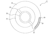
- FIG. 2 is a cross-sectional view showing the main frame of the scroll compressor according to the first embodiment from the upper surface side.
- FIG. 3 is a cross-sectional view showing a compression mechanism portion of the scroll compressor according to the first embodiment.
- FIG. 4 is a plan view showing the fixed scroll of the scroll compressor according to the first embodiment from the lower surface side.
- FIG. 5 is a plan view showing the swing scroll of the scroll compressor according to the first embodiment from the upper surface side.
- FIG. 1 is a vertical cross-sectional view schematically showing the internal structure of the scroll compressor according to the first embodiment.
- FIG. 2 is a cross-sectional view showing the main frame of the scroll compressor according to the first embodiment from the upper surface side.
- FIG. 3 is a cross-sectional view showing a compression mechanism portion of the scroll compressor according to the first embodiment.
- FIG. 4 is a plan view showing the fixed scroll of the
- the scroll compressor 100 according to the first embodiment is one of the components of the refrigerating cycle used in, for example, a refrigerator, a freezer, an air conditioner, a refrigerating device, a water heater, etc., and provides a refrigerant that circulates in the refrigerating cycle. It is sucked, compressed, and discharged in a high temperature and high pressure state.
- the scroll compressor 100 is a compression mechanism unit composed of a shell 1 forming an outer shell, a main frame 2 fixed to the inner wall surface of the shell 1, a fixed scroll 4, and a swing scroll 5. 3, an electric motor 6 for driving the compression mechanism unit 3, a crankshaft 7 for connecting the compression mechanism unit 3 and the electric motor 6, and a subframe 8.
- the shell 1 is a conductive member such as metal, and is formed in a tubular shape that forms a closed space.
- a main frame 2, a compression mechanism portion 3, an electric motor 6, and a crankshaft 7 are housed inside the shell 1. Further, an oil reservoir 18 for storing lubricating oil is provided on the inner bottom portion of the shell 1.
- the shell 1 is composed of a cylindrical main shell 1a, a substantially hemispherical upper shell 1b that closes the upper surface opening of the main shell 1a, and a substantially hemispherical lower shell 1c that closes the lower surface opening of the main shell 1a. ..
- the upper shell 1b and the lower shell 1c are respectively joined to the main shell 1a by welding or the like.
- the inner wall surface of the main shell 1a is formed below the large-diameter first inner wall surface 10a formed above and the first inner wall surface 10a, and is larger than the inner diameter of the first inner wall surface 10a. It has a second inner wall surface 10b having a small diameter.
- the first step portion 11a formed by the lower end of the first inner wall surface 10a and the upper end of the second inner wall surface 10b functions as a positioning portion of the main frame 2.
- the main shell 1a is provided with a suction pipe 13, a discharge pipe 14, and a power supply terminal 19.
- the suction pipe 13 is provided to take in the refrigerant from the outside to the inside of the shell 1.
- the illustrated suction pipe 13 communicates the outside of the shell 1 with the refrigerant suction space 31 surrounded by the fixed scroll 4 and the main frame 2, but the configuration is not limited to this, and the refrigerant is transferred to the shell 1. Any form may be used as long as it can be taken in from the outside to the inside.
- the discharge pipe 14 is provided to communicate the outside of the shell 1 with the motor space 16 provided with the electric motor 6 and discharge the refrigerant compressed in the compression chamber 30 to the outside of the shell 1.
- the suction pipe 13 and the discharge pipe 14 are joined to the main shell 1a by welding, brazing, or the like with a part inserted into the holes formed in the side wall of the main shell 1a.
- the refrigerant suction space 31 is a space located before the refrigerant taken in from the suction pipe 13 is taken into the compression chamber 30.
- the refrigerant suction space 31 is not limited to the space surrounded by the fixed scroll 4 and the main frame 2 shown, as long as it is a space located before the refrigerant taken in from the suction pipe 13 is taken into the compression chamber 30. , May be provided at other positions.
- the pressure of the refrigerant in the refrigerant suction space 31 is the refrigerant pressure before compression, which is a low pressure.
- the space provided above the fixed scroll 4 inside the shell 1 is a discharge space 15 that serves as an outlet for the refrigerant compressed in the compression chamber 30.
- the motor space 16 is below the main frame 2 and is a space provided with the electric motor 6. Further, inside the shell 1, a connecting passage 21 for communicating the discharge space 15 and the motor space 16 is provided as a flow path for the refrigerant compressed in the compression chamber 30.
- the pressure of the refrigerant in the discharge space 15, the motor space 16 and the connecting passage 21 is the pressure of the refrigerant after compression, which is a high pressure.
- the power supply terminal 19 is provided to supply power to the scroll compressor 100.
- the power feeding terminal 19 is a metal member, and as shown in FIG. 1, one end thereof is arranged outside the shell 1 and the other end is arranged inside the shell 1.
- the other end of the power supply terminal 19 arranged inside the shell 1 is connected to the electric motor 6 by the wiring 19a.
- the main frame 2 is a cylindrical metal frame that gradually tapers downward, and supports the swing scroll 5 swingably.
- the position of the main frame 2 in the vertical direction is determined by the outer peripheral surface of the upper portion being supported by the first step portion 11a of the main shell 1a.
- the main frame 2 is fixed to the inner wall surface of the main shell 1a by, for example, shrink fitting or welding in a state where the outer peripheral surface of the upper portion is supported by the first step portion 11a.
- the refrigerant suction space 31 and the motor space 16 are separated by airtightly fixing the contact surfaces between the main frame 2 and the main shell 1a.
- the upper surface of the main frame 2 is an annular flat surface 24.
- An isolation wall portion 20 that isolates the connecting passage 21 from the refrigerant suction space 31 is provided between the flat surface 24 of the main frame 2 and the fixed scroll 4.
- the isolation wall portion 20 has a configuration in which a part of the flat surface 24 of the main frame 2 projects toward the fixed scroll 4 and the fixed scroll 4 is supported at the upper end portion.
- the isolation wall portion 20 has a concave cross-sectional shape and is formed along the inner wall surface of the main shell 1a. The space surrounded by the isolation wall portion 20 and the inner wall surface of the main shell 1a becomes the connecting passage 21 isolated from the refrigerant suction space 31.
- the isolation wall portion 20 can be formed by a method such as casting.
- the connecting passage 21 is formed by the isolation wall portion 20 in an arc shape along the circumferential direction of the inner wall surface of the main shell 1a.
- the isolation wall portion 20 is arranged in a phase substantially opposite to the suction pipe 13. This is because the refrigerant sucked from the suction pipe 13 is easily taken into the compression chamber 30 without being subjected to suction pressure loss due to passing through a narrow flow path near the isolation wall portion 20.
- the connecting passage 21 is not limited to the arc shape shown in the figure, and may be an elongated shape along the circumferential direction of the inner wall surface of the main shell 1a, such as a rectangular shape, an elliptical shape, or an oval shape.
- the scroll compressor 100 can reduce the pressure loss of the refrigerant by widening the cross-sectional area of the flow path of the connecting passage 21.
- the flow path cross-sectional area of the connecting passage 21 may be set to 1 to 4 times the flow path cross-sectional area of the discharge pipe 14 as a guide.
- a first through hole 26 for communicating the space surrounded by the isolation wall portion 20 and the inner wall surface of the main shell 1a and the motor space 16 is formed on the outer peripheral surface of the main frame 2.
- the first through hole 26 forms a part of the connecting passage 21.
- the first through hole 26 is formed in a notch shape having substantially the same shape as the cross-sectional shape of the isolation wall portion 20.
- the first through hole 26 is not limited to the notch shape shown in the figure, and may be, for example, a hole surrounded by a periphery.
- the inside of the cylinder of the main frame 2 is formed so that the inner diameter gradually decreases downward.
- An old dam accommodating portion 25 is formed in the upper part of the inside of the cylinder, and a pair of first old dam grooves 22 formed so as to face each other with a shaft hole interposed therebetween are provided on a part of the old dam accommodating portion 25 and the flat surface 24. ing.
- the first Oldham groove 22 is a key groove.
- the lower portion inside the cylinder is a main bearing portion 23 that supports the crankshaft 7.
- the fixed scroll 4 has a disk-shaped fixed base plate 4a and a first spiral protrusion 4b provided on the lower surface of the fixed base plate 4a.
- the rocking scroll 5 is provided on the disc-shaped rocking base plate 5a and the upper surface of the rocking base plate 5a, and meshes with the first spiral protrusion 4b. It has two spiral protrusions 5b.
- the swing scroll 5 is installed so as to be eccentric with respect to the fixed scroll 4. By engaging the first spiral protrusion 4b of the fixed scroll 4 and the second spiral protrusion 5b of the swing scroll 5 with each other, the compression chamber 30 of the compression mechanism 3 is formed.
- the volume of the compression chamber 30 decreases from the outside to the inside in the radial direction of the fixed scroll 4 and the swing scroll 5.
- the refrigerant taken in from the outer end 4c of the first spiral protrusion 4b and the outer end 5c of the second spiral protrusion 5b is moved to the center side and gradually compressed.
- the fixed scroll 4 is made of a metal such as cast iron.
- the outer peripheral surface of the fixed base plate 4a is fixed to the first inner wall surface 10a of the main shell 1a by shrink fitting or welding or the like in a state where the fixed base plate 4a is supported by the isolation wall portion 20.
- a discharge port 40 is formed which communicates with the compression chamber 30 and discharges the compressed refrigerant having a high temperature and high pressure from the compression chamber 30.
- the discharge port 40 communicates with the discharge space 15 provided above the fixed scroll 4.
- a discharge valve 17 that opens and closes the discharge port 40 according to the pressure of the refrigerant is screwed to the upper surface of the fixed scroll 4. The discharge valve 17 opens the discharge port 40 when the refrigerant in the compression chamber 30 reaches a predetermined pressure.
- a second through hole 41 for communicating the space surrounded by the isolation wall portion 20 and the inner wall surface of the main shell 1a and the discharge space 15 is formed on the outer peripheral surface of the fixed base plate 4a.
- the second through hole 41 forms a part of the connecting passage 21.
- the second through hole 41 is formed in a notch shape having substantially the same shape as the cross-sectional shape of the isolation wall portion 20.
- the second through hole 41 is not limited to the notch shape shown in the figure, and may be, for example, a hole surrounded by a periphery.
- the swing scroll 5 is made of a metal such as aluminum. As shown in FIG. 1, the swing scroll 5 revolves with respect to the fixed scroll 4 without rotating with respect to the fixed scroll 4 by the old dam ring 52 for preventing the rotation.
- the surface of the rocking base plate 5a on the side where the second spiral protrusion 5b is not formed acts as a rocking scroll thrust bearing surface.
- a hollow cylindrical boss portion 50 is provided at the center of the swing scroll thrust bearing surface. The swing scroll 5 revolves as the eccentric shaft portion 71 of the crankshaft 7 inserted into the boss portion 50 rotates.
- the swing scroll thrust bearing surface is provided with a pair of second Oldham grooves 51 formed so as to face each other with the boss portion 50 interposed therebetween.
- the second Oldham groove 51 is an oval-shaped key groove.
- the pair of second Oldham grooves 51 are arranged so that the lines connecting them are orthogonal to the lines connecting the pair of first Oldam grooves 22.
- the Oldam ring 52 includes a ring portion, a first key portion, and a second key portion.
- the ring portion has an annular shape and is arranged in the old dam accommodating portion 25 of the main frame 2.
- the first key portion is provided on the lower surface of the ring portion.
- the first key portion is composed of a pair, and each is housed in a pair of first old dam grooves 22 of the main frame 2.
- the second key portion is provided on the upper surface of the ring portion.
- the second key portion is composed of a pair, and each is housed in a pair of second Oldham grooves 51 of the swing scroll 5.
- the position of the second spiral protrusion 5b of the rocking scroll 5 in the rotational direction is determined. That is, the old dam ring 52 positions the swing scroll 5 with respect to the main frame 2, and determines the phase of the second spiral protrusion 5b with respect to the main frame 2.
- the Oldam ring 52 when the swing scroll 5 revolves due to the rotation of the crankshaft 7, the first key portion slides on the first Oldam groove 22 and the second key portion slides on the second Oldam groove 51. This prevents the swing scroll 5 from rotating.
- the refrigerant comprises, for example, a halogenated hydrocarbon having a carbon double bond, a halogenated hydrocarbon having no carbon double bond, a hydrocarbon, or a mixture containing them in the composition.
- the halogenated hydrocarbon having a carbon double bond is an HFC refrigerant having a zero ozone layer destruction coefficient and a chlorofluorocarbon-based low GWP refrigerant, and tetrafluoropropenes such as HFO1234yf, HFO1234ze, and HFO1243zf having a chemical formula of C3H2F4 are available. Illustrated.
- halogenated hydrocarbon having no carbon double bond examples include a refrigerant in which R32 (difluoromethane) represented by CH2F2, R41 and the like are mixed.
- hydrocarbons examples include propane and propylene, which are natural refrigerants.
- the mixture examples include a mixed refrigerant in which R32, R41 and the like are mixed with HFO1234yf, HFO1234ze, HFO1243zf and the like.
- the electric motor 6 is provided below the main frame 2 and rotationally drives the swing scroll 5 connected via the crankshaft 7 with respect to the fixed scroll 4.
- the electric motor 6 includes an annular stator 6a fixed to the inner wall surface of the shell 1 by shrink fitting or the like, and a rotor 6b rotatably attached to face the inner side surface of the stator 6a.
- the stator 6a has, for example, a structure in which windings are wound around an iron core formed by laminating a plurality of electromagnetic steel plates via an insulating layer, and is formed in a ring shape in a plan view.
- the rotor 6b has a structure in which a permanent magnet is built in an iron core formed by laminating a plurality of electromagnetic steel sheets, and has a through hole penetrating in the vertical direction in the center.
- the crankshaft 7 is a metal rod-shaped member.
- the crankshaft 7 includes a spindle portion 70 and an eccentric shaft portion 71.
- the spindle portion 70 is a shaft that constitutes the main portion of the crankshaft 7, and the central axis thereof is arranged so as to coincide with the central axis of the main shell 1a.
- the spindle portion 70 is fixed to the through hole at the center of the rotor 6b by shrink fitting or the like, and is joined to the main bearing portion 23 provided at the center of the main frame 2 by shrink fitting or welding or the like to the lower part of the shell 1. It is rotatably supported by an auxiliary bearing portion 80 provided at the center of the subframe 8. Further, the spindle portion 70 is provided with a first balancer 73 at the upper portion and a second balancer 74 at the lower portion in order to offset the imbalance caused by the swing of the swing scroll 5.
- the eccentric shaft portion 71 is provided at the upper end portion of the spindle portion 70 so that the central shaft thereof is eccentric with respect to the central axis of the spindle portion 70.
- the eccentric shaft portion 71 is rotatably supported by the boss portion 50 of the swing scroll 5.
- the crankshaft 7 rotates with the rotation of the rotor 6b, and the swing scroll 5 is swiveled by the eccentric shaft portion 71.
- an oil passage 72 is provided so as to penetrate vertically along the axial direction.
- the subframe 8 is a metal frame.
- the subframe 8 is joined to the inner wall surface of the main shell 1a by shrink fitting, welding, or the like.
- the subframe 8 includes an auxiliary bearing portion 80 and an oil pump (not shown).
- the sub-bearing portion 80 is a ball bearing provided in the center of the sub-frame 8.
- the oil pump is a pump for sucking up the lubricating oil stored in the oil reservoir 18 of the shell 1, and is provided under the auxiliary bearing portion 80.
- Lubricating oil is stored in the oil reservoir 18 as shown in FIG. Lubricating oil is sucked up by the oil pump, passes through the oil passage 72 of the crankshaft 7, reduces wear between mechanically contacting parts such as the compression mechanism 3, temperature control of sliding parts, and sealability. Improve.
- a refrigerating machine oil containing an ester-based synthetic oil, or the like which is excellent in lubrication characteristics, electrical insulation, stability, refrigerant solubility, low-temperature fluidity, etc., and has an appropriate viscosity is preferable.
- the refrigerant before compression flows into the refrigerant suction space 31 from the suction pipe 13 and is taken into the compression chamber 30 formed by combining the fixed scroll 4 and the swing scroll 5.
- the refrigerant compressed in the compression chamber 30 is discharged from the discharge port 40 into the discharge space 15.
- the refrigerant filling the discharge space 15 is a high-pressure refrigerant after compression. After that, the high-pressure refrigerant moves from the discharge space 15 to the motor space 16 through the connecting passage 21, and is discharged from the discharge pipe 14 to the outside of the shell 1.
- the connecting passage 21 and the refrigerant suction space 31 are separated by the isolation wall portion 20 to ensure airtightness, and the high-pressure refrigerant filling the connecting passage 21 is the refrigerant. Since there is no leakage to the suction space 31, loss of power input can be suppressed and performance can be improved.
- the fixed base plate 4a of the fixed scroll 4 is supported by the isolation wall portion 20 of the main frame 2 and is positioned on the inner wall surface of the shell 1 in the vertical direction. It is fixed by shrink fitting or welding. That is, in the scroll compressor 100 of the first embodiment, since the main frame 2 or the fixed scroll 4 does not have an outer peripheral wall for fixing the main frame 2 and the fixed scroll 4, the swing scroll 5 is mainly used.
- the inner wall surface of the shell 1a can be expanded to the maximum, and the capacity of the compression chamber 30 can be expanded. Further, since the refrigerant suction space 31 can be expanded by expanding the capacity of the compression chamber 30, the area of the flow path of the refrigerant in the compression chamber 30 can be expanded.
- the scroll compressor 100 the pressure loss until the refrigerant flowing in from the suction pipe 13 is taken into the compression chamber 30 is reduced, and the cooling capacity and the heating capacity can be improved. Further, in the scroll compressor 100, the structure can be simplified by omitting the outer peripheral wall for fixing the main frame 2 and the fixed scroll 4, so that the workability of the main frame 2 is improved and the workability of the main frame 2 is improved. It is also possible to reduce the weight.
- the discharge space 15 and the motor space 16 are communicated with each other through a connecting passage 21 in order to discharge the compressed high-pressure refrigerant to the outside of the shell 1.
- the connecting passage 21 projects from a part of the flat surface 24 of the main frame 2 toward the fixed scroll 4, and is formed along the inner wall surface of the main shell 1a by the isolation wall portion 20 formed on the inner wall surface of the main shell 1a. It is formed in an arc shape along the above.
- the connecting passage 21 has a position and a shape that does not interfere with the operation of the fixed scroll 4 and the swing scroll 5, the fixed scroll 4 and the fixed scroll 4 by providing the connecting passage 21
- the capacity of the compression chamber 30 can be expanded without being affected by the size limitation of the swing scroll 5.
- the scroll compressor 100 has an arcuate recess 53 formed on the outer peripheral surface of the rocking base plate 5a of the rocking scroll 5 to avoid interference with the isolation wall portion 20. It may be configured.
- the recess 53 is formed by recessing the outer peripheral surface of the rocking base plate 5a that approaches the isolation wall portion 20 toward the center of the rocking base plate 5a. Since the scroll compressor 100 can prevent the rocking base plate 5a from coming into contact with the isolation wall portion 20 by providing the recess 53, the performance can be improved.
- the second spiral protrusion 5b hidden behind the rocking base plate 5a and not visible is shown by a broken line.
- the origin O shown in FIG. 6 represents the center of the boss portion 50.
- the angle in the circumferential direction of the rocking base plate 5a with respect to the straight line connecting the origin O and the second spiral protrusion 5b is defined as ⁇ .
- the straight line connecting the origin O and the outer end portion 5c of the second spiral protrusion 5b is 0 °
- the counterclockwise direction is the + direction.
- the counterclockwise direction is a direction in which the extension / opening angle of the second spiral protrusion 5b increases, and is a direction in which the spiral is unwound.
- the maximum value of the distance between the outer circumference of the rocking base plate 5a and the origin O is Rmax.
- Rmin be the distance between the outer circumference of the rocking base plate 5a of the portion where the recess 53 is formed and the origin O.
- the recess 53 and the connecting passage 21 have a configuration in which the center of gravity in the cross section is arranged within a range in which the angle ⁇ is 30 ° or more and 150 ° or less in the + direction. Due to the structure of the compression mechanism portion 3, the scroll compressor 100 prevents interference between the second spiral protrusion portion 5b and the isolation wall portion 20 if the center of gravity in the cross section of the recess 53 and the connecting passage 21 is within the above range. Because it can be done. That is, in the scroll compressor according to the first embodiment, by setting the center of gravity of the recess 53 and the cross section of the connecting passage 21 within the above range, a sufficient flow path area of the connecting passage 21 can be secured and the compression chamber 30 can be secured. It is possible to secure a sufficient volume of the above.
- the scroll compressor 100 by setting the centroid in the cross section of the connecting passage 21 to the above range, the outer end portion 4c of the first spiral protrusion 4b serving as the intake port of the refrigerant taken into the inside of the compression chamber 30
- the isolation wall portion 20 can be provided at a position away from the outer end portion 5c of the second spiral protrusion portion 5b. Therefore, in this scroll compressor 100, since the flow path near the intake port is not blocked by the isolation wall portion 20, pressure loss is unlikely to occur when the refrigerant is taken into the compression chamber 30, and the freezing capacity is high. Heating capacity is obtained.
- the recess 53 may be formed so that Rmin is 80% or more and 95% or less of Rmax.
- the area of the connecting passage 21 is widely secured due to the structure of the compression mechanism portion 3, and the interference between the second spiral protrusion portion 5b and the isolation wall portion 20 and the interference between the compression chamber 30 and the isolation wall portion 20. It is an effective range that can prevent.
- the scroll compressor 100 can prevent pressure loss of the refrigerant and reduce power input loss, so that the performance can be improved.
- the scroll compressor 100 includes the shell 1, the main frame 2, the fixed scroll 4, the swing scroll 5, the electric motor 6, the suction pipe 13, and the discharge pipe 14. And have. Inside the shell 1, above the fixed scroll 4, a discharge space 15 serving as an outlet for the refrigerant compressed in the compression chamber 30 and a connecting passage 21 for communicating the discharge space 15 and the motor space 16 are provided. .. An isolation wall portion 20 that isolates the connecting passage 21 from the refrigerant suction space 31 is provided between the main frame 2 and the fixed scroll 4.
- the fixed base plate 4a is fixed to the inner wall surface of the shell 1.
- the scroll compressor 100 has a structure in which the refrigerant compressed in the compression chamber 30 flows out from the discharge space 15 to the motor space 16 in which the electric motor 6 is arranged through the connecting passage 21. Since the plate 4a is fixed to the inner wall surface of the shell 1, the outer peripheral wall for fixing the main frame 2 and the fixed scroll 4 can be omitted, and the swing scroll 5 can be expanded to the inner wall surface of the main shell 1a as much as possible. The capacity of the compression chamber 30 can be expanded.
- the fixed base plate 4a is fixed to the inner wall surface of the shell 1 in a state of being supported by the isolation wall portion 20. That is, in the scroll compressor 100 according to the first embodiment, the fixed base plate 4a of the fixed scroll 4 is supported by the isolation wall portion 20 of the main frame 2, and the inner wall surface of the shell 1 is positioned in the vertical direction. It can be fixed by shrink fitting or welding. Therefore, in the scroll compressor 104 according to the first embodiment, the fixed base plate 4a and the main frame 2 can be kept in parallel by the isolation wall portion 20, so that the accuracy of the position where the fixed scroll 4 is fixed is improved. And the performance can be improved. Further, the work of fixing the fixing base plate 4a to the inner wall surface of the main shell 1a by shrink fitting or welding becomes easy.
- a recess 53 is formed on the outer peripheral surface of the rocking base plate 5a to avoid interference with the isolation wall portion 20. That is, in the scroll compressor 100 according to the first embodiment, the contact between the rocking base plate 5a and the isolation wall portion 20 can be prevented by providing the recess 53, so that a highly reliable structure can be realized.
- the angle ⁇ in the circumferential direction of the rocking base plate 5a with respect to the straight line connecting the center of the boss portion 50 and the outer end portion 5c of the second spiral protrusion 5b increases in the direction in which the extension angle increases. It is a configuration in which the centroids in the cross section are arranged within a range of 30 ° or more and 150 ° or less. That is, the scroll compressor 100 according to the first embodiment can prevent the second spiral protrusion 5b from interfering with the isolation wall portion 20, and secures a sufficient flow path area of the connecting passage 21 and compresses the scroll compressor 100. It is possible to secure a sufficient volume of the chamber 30 at the same time.
- the distance from the center of the boss portion 50 to the outer peripheral surface on which the recess 53 is formed is 80% or more and 95% or less of the maximum distance from the center of the boss portion 50 to the outer peripheral surface of the rocking base plate 5a. Is formed in. That is, in the scroll compressor 100 according to the first embodiment, while securing a wide area of the connecting passage 21, interference between the second spiral protrusion 5b and the isolation wall portion 20, and the compression chamber 30 and the isolation wall portion 20. Interference with can be prevented. By securing a large area of the connecting passage 21, the scroll compressor 100 can prevent pressure loss of the refrigerant and reduce power input loss, so that the performance can be improved.
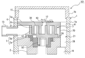
- FIG. 7 is a vertical cross-sectional view schematically showing an upper portion of the internal structure of the scroll compressor according to the second embodiment.
- the same configuration as that of the scroll compressor 100 described in the first embodiment is designated by the same reference numerals, and the description thereof will be omitted as appropriate.
- the configuration of the isolation wall portion 20 is different from that of the scroll compressor 100 of the first embodiment.
- the isolation wall portion 20 of the scroll compressor 101 according to the second embodiment projects from a part of the fixed base plate 4a of the fixed scroll 4 toward the flat surface 24 of the main frame 2.
- the lower end surface is supported by the flat surface 24 of the main frame 2.
- the isolation wall portion 20 has a concave cross-sectional shape and is formed along the inner wall surface of the main shell 1a.
- the space surrounded by the isolation wall portion 20 and the inner wall surface of the main shell 1a is the connecting passage 21.
- the connecting passage 21 and the refrigerant suction space 31 are separated by the isolation wall portion 20 to ensure airtightness, and the high-pressure refrigerant filling the connecting passage 21 is the refrigerant. Since there is no leakage to the suction space 31, loss of power input can be suppressed and performance can be improved.
- the fixed base plate 4a of the fixed scroll 4 is supported by the main frame 2 by the isolation wall portion 20, and is positioned on the inner wall surface of the shell 1 in the vertical direction. It is fixed by shrink fitting or welding. That is, in the scroll compressor 101 of the second embodiment, since the main frame 2 or the fixed scroll 4 does not have an outer peripheral wall for fixing the main frame 2 and the fixed scroll 4, the swing scroll 5 is mainly used.
- the inner wall surface of the shell 1a can be expanded to the maximum, and the capacity of the compression chamber 30 can be expanded. Further, by expanding the capacity of the compression chamber 30, the refrigerant suction space 31 can also be expanded, so that the area of the refrigerant flow path in the compression chamber 30 can be expanded.
- the scroll compressor 101 the pressure loss until the refrigerant flowing in from the suction pipe 13 is taken into the compression chamber 30 is reduced, and the cooling capacity and the heating capacity can be improved. Further, in the scroll compressor 101, the structure can be simplified and the weight can be reduced by omitting the outer peripheral wall for fixing the main frame 2 and the fixed scroll 4. Further, since the scroll compressor 101 has only a flat surface 24 on the upper surface of the main frame 2, it can be processed by a lathe when forming the main frame 2, and the workability is improved.
- the discharge space 15 and the motor space 16 are communicated with each other through a connecting passage 21 in order to discharge the compressed high-pressure refrigerant to the outside of the shell 1.
- the connecting passage 21 protrudes from a part of the fixed base plate 4a of the fixed scroll 4 toward the upper surface of the main frame 2, and is formed by the isolation wall portion 20 formed along the inner wall surface of the main shell 1a. It is formed in an arc shape along the inner wall surface of 1a.
- the connecting passage 21 has a position and a shape that does not interfere with the operation of the fixed scroll 4 and the swinging scroll 5, the fixed scroll 4 and the fixed scroll 4 by providing the connecting passage 21
- the capacity of the compression chamber 30 can be expanded without being affected by the size limitation of the swing scroll 5.
- FIG. 8 is a vertical cross-sectional view schematically showing an upper portion of the internal structure of the scroll compressor according to the third embodiment.
- the same configuration as that of the scroll compressor 100 described in the first embodiment is designated by the same reference numerals, and the description thereof will be omitted as appropriate.
- the configuration of the isolation wall portion 20 is different from the scroll compressor 100 of the first embodiment and the scroll compressor 101 of the second embodiment. ..
- the isolation wall portion 20 of the scroll compressor 102 according to the third embodiment has a first wall portion 20a protruding from a part of the flat surface 24 of the main frame 2 toward the fixed scroll 4 and a fixed base of the fixed scroll 4. It has a second wall portion 20b protruding from the plate 4a toward the flat surface 24 of the main frame 2, and is formed by abutting the upper end surface of the first wall portion 20a and the lower end surface of the second wall portion 20b. It is a composition.
- the isolation wall portion 20 has a concave cross-sectional shape and is formed along the inner wall surface of the main shell 1a. The space surrounded by the isolation wall portion 20 and the inner wall surface of the main shell 1a is the connecting passage 21.
- the scroll compressor 102 according to the third embodiment also has the same effect as the scroll compressor 100 of the first embodiment and the scroll compressor 101 of the second embodiment. Further, in the scroll compressor 102 according to the third embodiment, since the lengths of the first wall portion 20a and the second wall portion 20b are short, respectively, the outer diameters of the first wall portion 20a and the second wall portion 20b are processed. When doing so, the amount of deflection due to cutting resistance is reduced, and high machining accuracy can be obtained. Therefore, in the scroll compressor 102 according to the third embodiment, the airtightness between the connecting passage 21 and the refrigerant suction space 31 can be improved, and the performance can be improved.
- FIG. 9 is a vertical cross-sectional view schematically showing an upper portion of the internal structure of the scroll compressor according to the fourth embodiment.
- FIG. 10 is a cross-sectional view showing the main frame of the scroll compressor according to the fourth embodiment from the upper surface side.
- the same configurations as those of the scroll compressors 100 to 102 described in the first to third embodiments are designated by the same reference numerals, and the description thereof will be omitted as appropriate.
- the isolation wall portion 20 has a hollow structure, and the hollow inside of the isolation wall portion 20 is a connecting passage 21.
- the isolation wall portion 20 is configured to project from the flat surface 24 of the main frame 2 toward the fixed scroll 4 and support the fixed scroll 4 on the upper end surface.
- the outer diameter side of the isolation wall portion 20 is in contact with the inner wall surface of the main shell 1a.
- the first through hole 26 formed in the main frame 2 is a hole surrounded by a periphery. That is, in the scroll compressor 103 according to the fourth embodiment, the side surface on the outer diameter side of the isolation wall portion 20 and the outer peripheral surface of the upper portion of the main frame 2 are formed as the same plane continuous in the vertical direction. Can be done. That is, when lathe processing is performed to form the main frame 2, continuous cutting becomes possible, and consumption of processing tools can be reduced.
- the isolation wall portion 20 protrudes from the fixed base plate 4a of the fixed scroll 4 toward the flat surface 24 of the main frame 2, and the lower end surface is supported by the main frame 2. It may be configured. Further, as described in the third embodiment, the isolation wall portion 20 is mainly formed from the first wall portion 20a protruding from the upper surface of the main frame 2 toward the fixed scroll 4 and the fixed base plate 4a of the fixed scroll 4. The second wall portion 20b protruding toward the upper surface of the frame 2 may be provided, and the upper end surface of the first wall portion 20a and the lower end surface of the second wall portion 20b may be butted against each other.
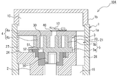
- FIG. 11 is a vertical cross-sectional view schematically showing an upper portion of the internal structure of the scroll compressor according to the fifth embodiment.
- FIG. 12 is a cross-sectional view showing the main frame of the scroll compressor according to the fifth embodiment from the upper surface side.
- the same configurations as those of the scroll compressors 100 to 103 described in the first to fourth embodiments are designated by the same reference numerals, and the description thereof will be omitted as appropriate.
- a support that projects from the flat surface 24 of the main frame 2 toward the fixed scroll 4 and supports the fixed base plate 4a on the upper end surface.
- a wall portion 27 is provided.
- two support wall portions 27 are provided at intervals along the outer peripheral edge of the upper surface of the main frame 2 so as not to interfere with the second spiral protrusion portion 5b of the swing scroll 5.
- the number of support wall portions 27 is not limited to the two shown in the figure, and may be one or three or more.
- the support wall portion 27 has a shape curved along the inner wall surface of the main shell 1a. Further, the upper end surface of the support wall portion 27 is located at substantially the same height as the upper end surface of the isolation wall portion 20. The fact that they are located at substantially the same height means that, for example, the difference in height between the support wall portion 27 and the isolation wall portion 20 is 0.5% or less of the height of the isolation wall portion 20. ..
- the fixing base plate 4a can be fixed to the inner wall surface of the main shell 1a by shrink fitting or the like. That is, in the scroll compressor 104 according to the fifth embodiment, the fixed base plate 4a is supported by the support wall portion 27 and the isolation wall portion 20 at a plurality of points, and the fixed base plate 4a and the main frame 2 are supported. Since it can be kept in a parallel state, the accuracy of the position where the fixed scroll 4 is fixed can be improved.
- the work of fixing the fixing base plate 4a to the inner wall surface of the main shell 1a by shrink fitting or welding becomes easy. Since the support wall portion 27 is provided along the inner wall surface of the main shell 1a so as not to interfere with the second spiral protrusion portion 5b of the swing scroll 5, it affects the expansion of the capacity of the compression chamber 30. It has no effect.
- FIG. 13 is a modification 1 of the scroll compressor according to the fifth embodiment, and is a vertical cross-sectional view schematically showing an upper portion of the internal structure.
- the support wall portion 27 may protrude from the fixed base plate 4a of the fixed scroll 4 toward the upper surface of the main frame 2, and the lower end surface may be supported by the flat surface 24 of the main frame 2. Good.
- the support wall portion 27 also has a shape curved along the inner wall surface of the main shell 1a.
- FIG. 14 is a modification 2 of the scroll compressor according to the fifth embodiment, and is a vertical cross-sectional view schematically showing an upper portion of the internal structure.
- the support wall portion 27 is formed on the first support wall portion 27a protruding from the upper surface of the main frame 2 toward the fixed base plate 4a of the fixed scroll 4 and from the fixed base plate 4a to the upper surface of the main frame 2. It may have a second support wall portion 27b protruding toward the surface, and the upper end surface of the first support wall portion 27a and the lower end surface of the second support wall portion 27b may be butted to support the fixed base plate 4a.
- the scroll compressor 104 of the second modification since the lengths of the first support wall portion 27a and the second support wall portion 27b are short, respectively, the outer diameters of the first support wall portion 27a and the second support wall portion 27b are processed. When doing so, the amount of deflection due to cutting resistance is reduced, and high machining accuracy can be obtained.
- the fixed base plate 4a is supported by the support wall portion 27 and the isolation wall portion 20 at a plurality of points, and the fixed base plate 4a is supported at a plurality of points. Since the 4a and the main frame 2 can be kept in a parallel state, the accuracy of the position where the fixed scroll 4 is fixed can be improved. Further, the work of fixing the fixing base plate 4a to the inner wall surface of the main shell 1a by shrink fitting or welding becomes easy.
- the isolation wall portion 20 shown in FIGS. 11 to 14 protrudes from the upper surface of the main frame 2 toward the fixed scroll 4, and the fixed scroll 4 is supported by the upper end surface.
- the configuration described in the third embodiment may be used.
- FIG. 15 is a vertical cross-sectional view schematically showing an upper portion of the internal structure of the scroll compressor according to the sixth embodiment.
- the same configuration as that of the scroll compressor 100 described in the first embodiment is designated by the same reference numerals, and the description thereof will be omitted as appropriate.
- a second step portion 11b that supports the outer peripheral surface of the fixed base plate 4a is formed on the inner wall surface of the shell 1.
- a third inner wall surface 10c having a diameter larger than the inner diameter of the first inner wall surface 10a is provided above the first inner wall surface 10a.
- the second step portion 11b is a step between the lower end of the third inner wall surface 10c and the upper end of the first inner wall surface 10a, is formed along the circumferential direction of the inner wall surface of the main frame 2, and functions as positioning of the fixed scroll 4. To do.
- the outer peripheral surface of the fixed base plate 4a is supported by the second step portion 11b, and the fixed scroll 4 is positioned in the vertical direction by shrink fitting or welding to the third inner wall surface 10c of the main shell 1a. It is fixed.
- the accuracy of the position where the fixed scroll 4 is fixed can be improved by the second step portion 11b formed along the circumferential direction of the inner wall surface of the main frame 2.
- the accuracy of the parallel state between the fixed base plate 4a and the main frame 2 can be improved.
- the posture of the swing scroll 5 is determined by contacting with the fixed base plate 4a or the main frame 2. That is, in the scroll compressor 105 according to the sixth embodiment, the accuracy of the parallel state between the fixed base plate 4a and the main frame 2 can be improved, so that the upper end surface of the second spiral protrusion 5b and the fixed base plate can be improved.
- the gap S between the lower surface and the lower surface of 4a can be made small, and the performance can be improved.
- the isolation wall portion 20 may have a configuration in which the fixed base plate 4a of the fixed scroll 4 projects toward the flat surface 24 of the main frame 2. In this case as well, there is no problem even if a minute gap S of, for example, about 10 ⁇ m to 100 ⁇ m exists between the lower end surface of the isolation wall portion 20 and the flat surface 24 of the main frame 2.
- FIG. 16 is a modification 1 of the scroll compressor according to the sixth embodiment, and is an enlarged view of a main part.
- FIG. 17 is a modification 1 of the scroll compressor according to the sixth embodiment, and is a plan view showing the main frame from the upper surface side.
- the scroll compressor 105 according to the sixth embodiment is a seal that fills a gap S between the isolation wall portion 20 and the fixed base plate 4a at the upper end portion of the isolation wall portion 20.
- the member 9 may be provided.
- a groove 90 for fitting the seal member 9 is formed on the upper end surface of the isolation wall portion 20, and the seal member 9 is fitted and fixed in the groove 90.
- the seal member 9 is a resin material such as PTFE or PPS.
- the isolation wall portion 20 is pressed against the fixed base plate 4a by receiving the differential pressure between the high-pressure refrigerant in the connecting passage 21 and the low-pressure refrigerant in the compression chamber 30, and the seal member 9 is pressed against the fixed base plate 4a. Be pressed. That is, in the scroll compressor 105, the seal member 9 can completely fill the gap S between the isolation wall portion 20 and the fixed base plate 4a, so that the refrigerant leaks from the connecting passage 21 to the refrigerant suction space 31. It can be reliably prevented and the performance can be improved.
- FIG. 18 is a modification 2 of the scroll compressor according to the sixth embodiment, and is an enlarged view of a main part.
- the isolation wall portion 20 projects from the fixed base plate 4a of the fixed scroll 4 toward the flat surface 24 of the main frame 2, and is supported by the fixed scroll 4 via a seal member 9 provided on the lower end surface. It may be the configuration that has been set.
- the scroll compressors 100 to 105 have been described above based on the embodiment, the scroll compressors 100 to 105 are not limited to the configuration of the above-described embodiment.
- the internal configuration of the scroll compressors 100 to 105 shown is not limited to the above-mentioned contents, and may include other components.
- the scroll compressors 100 to 105 include a range of design changes and application variations normally performed by those skilled in the art within a range that does not deviate from the technical idea thereof.
Landscapes
- Engineering & Computer Science (AREA)
- Mechanical Engineering (AREA)
- General Engineering & Computer Science (AREA)
- Applications Or Details Of Rotary Compressors (AREA)
- Rotary Pumps (AREA)
Priority Applications (4)
| Application Number | Priority Date | Filing Date | Title |
|---|---|---|---|
| JP2021532594A JP7345550B2 (ja) | 2019-07-16 | 2019-07-16 | スクロール圧縮機 |
| PCT/JP2019/027902 WO2021009839A1 (ja) | 2019-07-16 | 2019-07-16 | スクロール圧縮機 |
| EP19937692.2A EP4001650B1 (en) | 2019-07-16 | 2019-07-16 | Scroll compressor |
| CN201980098307.0A CN114072580B (zh) | 2019-07-16 | 2019-07-16 | 涡旋压缩机 |
Applications Claiming Priority (1)
| Application Number | Priority Date | Filing Date | Title |
|---|---|---|---|
| PCT/JP2019/027902 WO2021009839A1 (ja) | 2019-07-16 | 2019-07-16 | スクロール圧縮機 |
Publications (1)
| Publication Number | Publication Date |
|---|---|
| WO2021009839A1 true WO2021009839A1 (ja) | 2021-01-21 |
Family
ID=74210342
Family Applications (1)
| Application Number | Title | Priority Date | Filing Date |
|---|---|---|---|
| PCT/JP2019/027902 Ceased WO2021009839A1 (ja) | 2019-07-16 | 2019-07-16 | スクロール圧縮機 |
Country Status (4)
| Country | Link |
|---|---|
| EP (1) | EP4001650B1 (https=) |
| JP (1) | JP7345550B2 (https=) |
| CN (1) | CN114072580B (https=) |
| WO (1) | WO2021009839A1 (https=) |
Families Citing this family (1)
| Publication number | Priority date | Publication date | Assignee | Title |
|---|---|---|---|---|
| CN116412130A (zh) * | 2021-12-31 | 2023-07-11 | 丹佛斯(天津)有限公司 | 涡旋压缩机 |
Citations (6)
| Publication number | Priority date | Publication date | Assignee | Title |
|---|---|---|---|---|
| JP2003148348A (ja) * | 2001-11-15 | 2003-05-21 | Mitsubishi Electric Corp | 圧縮機 |
| JP2003286949A (ja) | 2002-03-28 | 2003-10-10 | Daikin Ind Ltd | 高低圧ドーム型圧縮機 |
| JP2006097517A (ja) * | 2004-09-29 | 2006-04-13 | Fujitsu General Ltd | 圧縮機および圧縮機用電動機 |
| JP2010001816A (ja) * | 2008-06-20 | 2010-01-07 | Sanden Corp | スクロール型流体機械 |
| WO2018163233A1 (ja) * | 2017-03-06 | 2018-09-13 | 三菱電機株式会社 | スクロール圧縮機および冷凍サイクル装置 |
| JP2018141444A (ja) * | 2017-02-28 | 2018-09-13 | サンデン・エンバイロメントプロダクツ株式会社 | オルダム継手構造、スクロール圧縮機、冷凍回路システム |
Family Cites Families (3)
| Publication number | Priority date | Publication date | Assignee | Title |
|---|---|---|---|---|
| EP2461122B1 (en) * | 2009-07-28 | 2018-12-19 | Mitsubishi Electric Corporation | Heat pump device, compressor with injection mechanism, and method of manufacturing scroll compressor with injection mechanism |
| JP2017025762A (ja) * | 2015-07-21 | 2017-02-02 | ダイキン工業株式会社 | 圧縮機 |
| JP6765508B2 (ja) * | 2017-03-29 | 2020-10-07 | 三菱電機株式会社 | スクロール圧縮機、およびスクロール圧縮機の製造方法 |
-
2019
- 2019-07-16 WO PCT/JP2019/027902 patent/WO2021009839A1/ja not_active Ceased
- 2019-07-16 EP EP19937692.2A patent/EP4001650B1/en active Active
- 2019-07-16 JP JP2021532594A patent/JP7345550B2/ja active Active
- 2019-07-16 CN CN201980098307.0A patent/CN114072580B/zh active Active
Patent Citations (6)
| Publication number | Priority date | Publication date | Assignee | Title |
|---|---|---|---|---|
| JP2003148348A (ja) * | 2001-11-15 | 2003-05-21 | Mitsubishi Electric Corp | 圧縮機 |
| JP2003286949A (ja) | 2002-03-28 | 2003-10-10 | Daikin Ind Ltd | 高低圧ドーム型圧縮機 |
| JP2006097517A (ja) * | 2004-09-29 | 2006-04-13 | Fujitsu General Ltd | 圧縮機および圧縮機用電動機 |
| JP2010001816A (ja) * | 2008-06-20 | 2010-01-07 | Sanden Corp | スクロール型流体機械 |
| JP2018141444A (ja) * | 2017-02-28 | 2018-09-13 | サンデン・エンバイロメントプロダクツ株式会社 | オルダム継手構造、スクロール圧縮機、冷凍回路システム |
| WO2018163233A1 (ja) * | 2017-03-06 | 2018-09-13 | 三菱電機株式会社 | スクロール圧縮機および冷凍サイクル装置 |
Also Published As
| Publication number | Publication date |
|---|---|
| JP7345550B2 (ja) | 2023-09-15 |
| EP4001650A1 (en) | 2022-05-25 |
| CN114072580B (zh) | 2023-06-23 |
| CN114072580A (zh) | 2022-02-18 |
| EP4001650B1 (en) | 2025-10-22 |
| JPWO2021009839A1 (https=) | 2021-01-21 |
| EP4001650A4 (en) | 2022-07-27 |
Similar Documents
| Publication | Publication Date | Title |
|---|---|---|
| US11143184B2 (en) | Scroll compressor, refrigeration cycle apparatus, and shell | |
| JP6765508B2 (ja) | スクロール圧縮機、およびスクロール圧縮機の製造方法 | |
| JPWO2019087227A1 (ja) | スクロール圧縮機 | |
| JP7118177B2 (ja) | スクロール圧縮機 | |
| CN113396285B (zh) | 旋转式压缩机、旋转式压缩机的制造方法及制冷循环装置 | |
| WO2021009839A1 (ja) | スクロール圧縮機 | |
| JP7055245B2 (ja) | スクロール圧縮機及びそのスクロール圧縮機の製造方法 | |
| JP7433697B2 (ja) | スクロール圧縮機及び当該スクロール圧縮機を使用した冷凍サイクル装置 | |
| CN112005012A (zh) | 涡旋式压缩机 | |
| JP2021076085A (ja) | スクロール圧縮機 | |
| JP7727004B2 (ja) | スクロール圧縮機およびその製造方法 | |
| WO2021084607A1 (ja) | スクロール圧縮機および冷凍サイクル装置 | |
| US20240410367A1 (en) | Scroll compressor | |
| JPWO2019207785A1 (ja) | スクロール圧縮機 | |
| JP7076537B2 (ja) | スクロール圧縮機 | |
| JP7191246B2 (ja) | スクロール圧縮機および冷凍サイクル装置 | |
| JP7361585B2 (ja) | スクロール圧縮機及びスクロール圧縮機の製造方法 | |
| WO2023188422A1 (ja) | 圧縮機およびアッパーシェル | |
| WO2021245754A1 (ja) | スクロール圧縮機及び冷凍サイクル装置 | |
| WO2025192697A1 (ja) | スクロール圧縮機及び冷凍サイクル装置 | |
| WO2023276020A1 (ja) | スクロール圧縮機 | |
| WO2022059195A1 (ja) | スクロール圧縮機 | |
| WO2023079667A1 (ja) | スクロール圧縮機およびこのスクロール圧縮機を備えた冷凍サイクル装置 | |
| WO2021014641A1 (ja) | スクロール圧縮機 |
Legal Events
| Date | Code | Title | Description |
|---|---|---|---|
| 121 | Ep: the epo has been informed by wipo that ep was designated in this application |
Ref document number: 19937692 Country of ref document: EP Kind code of ref document: A1 |
|
| ENP | Entry into the national phase |
Ref document number: 2021532594 Country of ref document: JP Kind code of ref document: A |
|
| NENP | Non-entry into the national phase |
Ref country code: DE |
|
| ENP | Entry into the national phase |
Ref document number: 2019937692 Country of ref document: EP Effective date: 20220216 |
|
| WWG | Wipo information: grant in national office |
Ref document number: 2019937692 Country of ref document: EP |