WO2020261699A1 - 電気掃除機 - Google Patents
電気掃除機 Download PDFInfo
- Publication number
- WO2020261699A1 WO2020261699A1 PCT/JP2020/015400 JP2020015400W WO2020261699A1 WO 2020261699 A1 WO2020261699 A1 WO 2020261699A1 JP 2020015400 W JP2020015400 W JP 2020015400W WO 2020261699 A1 WO2020261699 A1 WO 2020261699A1
- Authority
- WO
- WIPO (PCT)
- Prior art keywords
- vacuum cleaner
- electric blower
- main body
- case
- handle
- Prior art date
Links
Images


Classifications
-
- A—HUMAN NECESSITIES
- A47—FURNITURE; DOMESTIC ARTICLES OR APPLIANCES; COFFEE MILLS; SPICE MILLS; SUCTION CLEANERS IN GENERAL
- A47L—DOMESTIC WASHING OR CLEANING; SUCTION CLEANERS IN GENERAL
- A47L5/00—Structural features of suction cleaners
- A47L5/12—Structural features of suction cleaners with power-driven air-pumps or air-compressors, e.g. driven by motor vehicle engine vacuum
- A47L5/22—Structural features of suction cleaners with power-driven air-pumps or air-compressors, e.g. driven by motor vehicle engine vacuum with rotary fans
- A47L5/28—Suction cleaners with handles and nozzles fixed on the casings, e.g. wheeled suction cleaners with steering handle
- A47L5/30—Suction cleaners with handles and nozzles fixed on the casings, e.g. wheeled suction cleaners with steering handle with driven dust-loosening tools, e.g. rotating brushes
-
- A—HUMAN NECESSITIES
- A47—FURNITURE; DOMESTIC ARTICLES OR APPLIANCES; COFFEE MILLS; SPICE MILLS; SUCTION CLEANERS IN GENERAL
- A47L—DOMESTIC WASHING OR CLEANING; SUCTION CLEANERS IN GENERAL
- A47L9/00—Details or accessories of suction cleaners, e.g. mechanical means for controlling the suction or for effecting pulsating action; Storing devices specially adapted to suction cleaners or parts thereof; Carrying-vehicles specially adapted for suction cleaners
-
- Y—GENERAL TAGGING OF NEW TECHNOLOGICAL DEVELOPMENTS; GENERAL TAGGING OF CROSS-SECTIONAL TECHNOLOGIES SPANNING OVER SEVERAL SECTIONS OF THE IPC; TECHNICAL SUBJECTS COVERED BY FORMER USPC CROSS-REFERENCE ART COLLECTIONS [XRACs] AND DIGESTS
- Y02—TECHNOLOGIES OR APPLICATIONS FOR MITIGATION OR ADAPTATION AGAINST CLIMATE CHANGE
- Y02E—REDUCTION OF GREENHOUSE GAS [GHG] EMISSIONS, RELATED TO ENERGY GENERATION, TRANSMISSION OR DISTRIBUTION
- Y02E60/00—Enabling technologies; Technologies with a potential or indirect contribution to GHG emissions mitigation
- Y02E60/10—Energy storage using batteries
Definitions
- the present invention relates to a vacuum cleaner.
- the vacuum cleaner of Patent Document 1 has a dust collecting chamber for collecting dust, a motor provided behind the dust collecting chamber to generate an air flow for sucking the dust, and a motor arranged behind the motor.
- a noise reduction plate for reducing the noise generated by the motor is provided, and the noise reduction plate is provided on the opposite side of the motor side from the shrink chamber having the first hole width provided on the motor side. It has a plurality of through holes formed with an expansion chamber having a second hole width wider than the first hole width, and the air flow generated by driving the motor passes through the plurality of through holes. It is configured to be exhausted.
- an object of the present invention is to provide an electric vacuum cleaner that can effectively reduce noise while having a simple structure.
- the vacuum cleaner according to the embodiment of the present invention provided to solve the above-mentioned problems includes a dust collecting unit for collecting dust, an electric blower for generating an air flow for sucking dust, and the electric blower.
- a cover body provided in a state separated from the electric blower and an exhaust port provided on the exhaust side of the cover body and exhausting the exhaust air generated by the electric blower to the outside are provided.
- the cover body is characterized by including a wind direction guide portion that guides the wind direction of the exhaust air to the suction side of the electric blower.
- the exhaust air generated by the electric blower passes between the exhaust side of the electric blower and the cover body and is discharged from the exhaust port.
- the cover body is provided with a wind direction guide portion, and the wind direction of the exhaust air can be guided to the suction side of the electric blower. As a result, the noise associated with the operation of the electric blower can be reduced. Therefore, according to the present invention, it is possible to provide an electric vacuum cleaner having a simple structure and effectively obtaining a noise reduction effect.
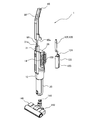
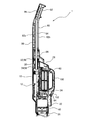
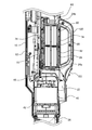
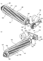
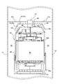
- FIG. 1 It is a perspective view which shows the state which the vacuum cleaner which concerns on one Embodiment of this invention is seen from the back side. It is an exploded perspective view of the electric vacuum cleaner shown in FIG. It is an enlarged sectional view of the main part of the electric vacuum cleaner of FIG. It is an enlarged sectional view of the main part of the electric vacuum cleaner of FIG. (A) is a perspective view showing a state in which the battery pack is stored in the battery pack storage portion as viewed from the bottom side, and (b) is a perspective view showing a state as seen from the top surface side. It is an exploded perspective view which shows the battery pack storage part and the battery pack. FIG.
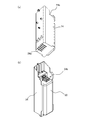
- FIG. 5 is an enlarged cross-sectional view of a main part showing a state in which the vacuum cleaner main body and the first handle of the vacuum cleaner of FIG. 1 are separated. It is sectional drawing which shows the electric blower unit included in the vacuum cleaner shown in FIG. It is an exploded perspective view which shows the electric blower unit included in the vacuum cleaner shown in FIG. It is sectional drawing which shows the 1st handle provided in the vacuum cleaner shown in FIG. It is an exploded perspective view which shows the 1st handle provided in the vacuum cleaner shown in FIG. It is a perspective view which shows the auxiliary dust collecting part which the electric vacuum cleaner shown in FIG. 1 has. It is a top view which showed the attached state of the cleaning body while partially breaking the suction part provided in the electric vacuum cleaner shown in FIG. FIG.
- FIG. 13 is an enlarged view of an area surrounded by the alternate long and short dash line in FIG.
- (A) is an exploded perspective view showing the mounting structure of the cleaning body with respect to the mounting portion and the state of the cleaning body driving mechanism viewed from the first direction, and (b) shows a state viewed from a direction different from (a).
- It is an enlarged sectional view of the main part which shows the modification which provided the plate-shaped member between the electric blower unit and a battery pack.
- It is an enlarged sectional view of the main part which shows the modification which attached the cover body to the end face on the upstream side in the flow direction of an air flow in a battery pack storage part.
- It is an enlarged cross-sectional view of a main part which concerns on the modification which attached the cover body via a vibration-proof member.
- the vacuum cleaner 1 according to the embodiment of the present invention will be described in detail with reference to the drawings.
- the overall configuration of the vacuum cleaner 1 will be outlined, and then the main parts will be described in more detail.
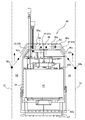
- the positional relationship in the vertical direction, the width direction, etc. will be described with reference to the state in which the vacuum cleaner 1 is erected as shown in FIG.
- the vacuum cleaner 1 is a vacuum cleaner having a stick-shaped (vertical) appearance.
- the vacuum cleaner 1 can be, for example, a vacuum cleaner that obtains electric power from an external power source via a power cord, but is rechargeable in the present embodiment.
- the vacuum cleaner 1 includes a vacuum cleaner main body 10, a dust collecting unit 20, an auxiliary dust collecting unit 120, and a suction unit 140.
- the vacuum cleaner main body 10 is a part that forms the main body of the electric vacuum cleaner 1 and exerts a suction force to collect dust.
- the vacuum cleaner main body 10 has an electric blower unit 40 for sucking air and generating an air flow inside the main body case 12 forming a housing, a battery pack 60, and a battery pack 60. It is equipped with other parts.
- the vacuum cleaner main body 10 is provided with a first handle 80 and a second handle 100 on the outside.
- the first handle 80 and the second handle 100 are for being gripped by the user of the vacuum cleaner 1, respectively.
- the first handle 80 is a rod-shaped portion provided so as to continue in the longitudinal direction of the vacuum cleaner main body 10, and is designed so that the user can hold it by hand.
- the second handle 100 is provided on the peripheral portion (rear side in the present embodiment) of the vacuum cleaner main body 10.
- the second handle 100 is provided assuming a case where the vacuum cleaner 1 is used in a state where the first handle 80 is removed from the vacuum cleaner main body 10.
- the second handle 100 is configured so that the vacuum cleaner main body 10 can be gripped by, for example, a user passing a finger other than the thumb through the opening portion.
- a first operation unit 86 and a second operation unit 102 are provided at or near the first handle 80 and the second handle 100.
- the first operation unit 86 and the second operation unit 102 are for operating the vacuum cleaner 1, respectively, and are for performing, for example, on / off operation of the power supply.
- the dust collecting unit 20 is a part where dust sucked by the vacuum cleaner 1 is collected.
- the dust collecting unit 20 is provided so as to be continuous with the vacuum cleaner main body 10.
- the lower end side of the dust collecting portion 20 is opened so that the suction portion 140 can be connected.
- the suction portion 140 includes a suction portion main body 142 and a joint portion 144. Further, as shown in FIG. 13, the suction unit 140 includes members such as a cleaning body 146 and a cleaning body drive mechanism 148 inside the suction unit main body 142.
- the suction portion main body 142 is a portion arranged on the floor during cleaning, and has a shape long in the left-right direction with respect to the front-rear direction which is the direction operated by the user during cleaning. Inside the suction portion main body 142, a suction space for sucking air and dust from the outside is formed with the floor surface side as the opening end.
- the joint portion 144 is rotatably attached to the suction portion main body 142 within a predetermined rotation range (front-rear direction and left-right direction).
- the joint portion 144 is a portion connected to the dust collecting portion 20 described above.
- the joint portion 144 has a tubular shape, and the internal space communicates with the suction space.
- the vacuum cleaner 1 is generally configured as described above.
- the electric vacuum cleaner 1 is housed inside the vacuum cleaner main body 10 (structure and arrangement of devices built in the main body case 12 such as the electric blower unit 40 and the battery pack 60), the first handle 80 and the second.
- Each part is provided with a characteristic structure such as a handle 100, an auxiliary dust collecting part 120 and the like provided outside the main body case 12, and a suction part 140 and the like.
- a handle 100 a handle 100, an auxiliary dust collecting part 120 and the like provided outside the main body case 12, and a suction part 140 and the like.
- the vacuum cleaner main body 10 stores the electric blower unit 40, the battery pack 60, and the like in the hollow main body case 12 forming the housing, and one end side and the other end side of the main body case 12.
- the dust collecting unit 20 and the first handle 80 can be connected to the dust collecting unit 20.
- the configuration of the main body case 12 will be described first, and then the electric blower unit 40, the battery pack 60, and the like will be described.
- the main body case 12 is provided with an electric blower unit storage portion 22 and a battery pack storage portion 24 inside, and is provided with a dust collector connection portion 26 and a first handle connection portion 28 on one end side and the other end side in the longitudinal direction. is there.
- the electric blower unit 40 and the battery pack 60 which will be described in detail later, are stored in the electric blower unit storage unit 22 and the battery pack storage unit 24, respectively.
- the dust collecting unit connecting portion 26 is a portion to which the dust collecting unit 20 is connected.
- the dust collecting portion connecting portion 26 is open so as to be able to communicate with the dust collecting portion 20.
- the first handle connecting portion 28 is a portion to which the first handle 80 is connected.
- the first handle connecting portion 28 has an accommodating portion 30 and an engaging portion 34.
- the accommodating portion 30 is a portion for accommodating the protruding portion 96 of the first handle 80, which will be described in detail later, without exposing it.
- the accommodating portion 30 is formed in a concave shape in the axial direction of the main body case 12 while opening at the end of the main body case 12 so that the protruding portion 96 of the first handle 80 can be inserted.
- the engaging portion 34 engages with the engaged portion 98 formed by holes, recesses, etc. in the protruding portion 96 of the first handle 80, which will be described in detail later, and is connected to the main body case 12. It locks 80.
- the engaging portion 34 engages with the engaged portion 98 by being urged by the urging member in the direction in which the engaging portion 34 and the engaged portion 98 approach each other on one end side of the rotating shaft. On the other hand, when a force is applied on the other end side of the rotating shaft in a direction opposite to the urging direction, the engagement between the engaging portion 34 and the engaged portion 98 is released.
- a part or the whole of the end face forming the first handle connecting portion 28 (substantially the whole in the present embodiment) is inclined or curved according to the end face of the handle case 82 forming the first handle 80, which will be described in detail later. (In the present embodiment, it is an inclined shape).
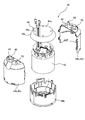
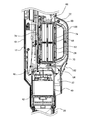
- the electric blower unit 40 includes an electric blower 42, an electric blower case 44, and a cover body 46.
- the electric blower unit 40 has a configuration in which the electric blower 42 is housed inside the electric blower case 44, and a cover body 46 is attached to the electric blower case 44.
- the electric blower unit 40 is housed in the electric blower unit storage unit 22 in a posture in which the axial direction faces the longitudinal direction of the main body case 12 described above. Therefore, in the vacuum cleaner 1, the electric blower unit 40 is arranged on the downstream side in the flow direction of the air flow with respect to the dust collecting unit 20.
- the electric blower 42 is for generating an air flow for sucking dust.
- the electric blower 42 has an intake unit 42a and an exhaust unit 42b, and can generate an air flow from the intake unit 42a to the exhaust unit 42b by supplying electric power.
- the electric blower 42 is arranged so that the intake portion 42a faces the dust collecting portion 20 side.
- the electric blower 42 is housed in the electric blower case 44.
- the electric blower case 44 is a case for accommodating the above-mentioned electric blower 42.
- the electric blower case 44 may have any form as long as it can accommodate the electric blower 42.
- the intake side case 44a and the exhaust side case 44b are combined. It is preferable to use a tubular one.
- the exhaust side case 44b is further configured by combining the first exhaust side case 44c and the second exhaust side case 44d.
- the intake side case 44a and the exhaust side case 44b are combined in a state where the intake side case 44a accommodates the intake portion 42a side of the electric blower 42 and the exhaust side case 44b accommodates the exhaust portion 42b side.
- the electric blower case 44 has an intake opening 47 and an exhaust opening 48 on one end side and the other end side.
- the intake opening 47 is provided in the intake side case 44a
- the exhaust opening 48 is provided in the exhaust side case 44b.
- the electric blower case 44 has a convex boss portion 50 on the exhaust side case 44b.
- a plurality of boss portions 50 are arranged at substantially equal intervals on the end surface of the exhaust side case 44b in the circumferential direction.
- the boss portion 50 functions as a fixing member for fixing the cover body 46, which will be described in detail later.
- the cover body 46 is a member arranged on the exhaust side with respect to the electric blower 42.
- the cover body 46 is arranged by being fixed by the boss portion 50 to the exhaust side case 44b of the electric blower case 44 in which the electric blower 42 is housed.
- the cover body 46 is formed so as to have a dish-like appearance shape.
- the cover body 46 is provided in a state of being separated from the electric blower 42 and the electric blower case 44. Therefore, the cover body 46 does not close the exhaust opening 48 of the electric blower case 44, and the blower exhaust passage 52 through which the exhaust gas discharged from the exhaust opening 48 flows between the electric blower case 44 and the cover body 46. Is forming.
- the cover body 46 has a wind receiving portion 46a (flat portion), a bent portion 46b, and a wind direction guiding portion 46c.
- the wind receiving portion 46a is a portion that receives the exhaust of the electric blower 42 discharged from the exhaust opening 48.
- the wind receiving portion 46a has a flat shape and is substantially parallel to the end surface of the electric blower case 44.
- the cover body 46 is bent toward the intake opening 47 side of the electric blower case 44 at the bent portion 46b on the outer peripheral side with respect to the wind receiving portion 46a, and is connected to the wind direction guide portion 46c. That is, the wind direction guide portion 46c is on the downstream side in the exhaust flow direction with respect to the wind receiving portion 46a.
- the wind direction guide portion 46c guides the wind direction of the exhaust air of the electric blower 42 discharged from the exhaust opening to the suction side (intake opening 47 side) of the electric blower 42.
- the blower exhaust passage 52 has a first passage portion 52a and a second passage portion 52b.
- the first passage portion 52a is a portion that extends in the direction along the exhaust side end surface between the end surface (exhaust side end surface) of the electric blower case 44 on the exhaust opening 48 side and the air receiving portion 46a of the cover body 46. .. Therefore, the first passage portion 52a can guide the exhaust gas discharged from the exhaust opening portion 48 and received by the wind receiving portion 46a toward the outer peripheral side (diameter outside) of the electric blower case 44.
- the second passage portion 52b is electrically operated between the exhaust side end surface of the electric blower case 44 (a chamfered portion on the outer peripheral portion of the exhaust side end surface in the present embodiment) and the wind direction guide portion 46c of the cover body 46. It is a portion formed so as to incline toward the suction side (intake opening 47 side) of the blower 42.
- the second passage portion 52b communicates with the first passage portion 52a.
- the end portion of the second passage portion 52b is an exhaust port 52c, and the exhaust generated by the electric blower 42 can be discharged to the outside of the electric blower 42.
- the second passage portion 52b can discharge the exhaust gas flowing through the first passage portion 52a through the exhaust port 52c and guide the exhaust gas to the suction side (intake opening 47 side) of the electric blower 42.
- the inner peripheral surface of the main body case 12 exists on the extension line of the second passage portion 52b. Further, there is a gap 54 between the end of the second passage portion 52b and the inner peripheral surface of the main body case 12. Therefore, the exhaust gas discharged through the second passage portion 52b collides with the inner peripheral surface of the main body case 12, and then flows through the gap 54 toward the downstream side inside the main body case 12.
- the electric blower unit 40 and its surroundings may be provided with a sound absorbing material for reducing noise caused by exhaust gas, although it is not an essential configuration.
- the electric blower unit 40 is provided with the first sound absorbing material 56a on the cover body 46.
- the first sound absorbing material 56a may be provided, for example, in the wind receiving portion 46a, the wind direction guiding portion 46c, or the like.
- a second sound absorbing material 56b is provided on the extension line of the second passage portion 52b.
- the second sound absorbing material 56b may be arranged at a position where it intersects with the inner peripheral surface of the main body case 12, for example, on an extension line of the second passage portion 52b of the blower exhaust passage 52. As a result, it is possible to suppress the noise generated when the exhaust gas discharged through the blower exhaust passage 52 collides with the main body case 12.
- the battery pack 60 supplies electric power to a member such as the electric blower unit 40.
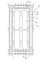
- the battery pack 60 includes a battery case 66 and a battery 68 provided inside the battery case 66.
- the battery case 66 is a hollow case.
- the battery pack 60 is stored in the battery pack storage unit 24 provided inside the main body case 12.
- the battery pack 60 is arranged on the downstream side in the flow direction of the air flow (exhaust) flowing inside the main body case 12 with respect to the above-mentioned electric blower unit 40. That is, the battery pack 60 is arranged above the electric blower unit 40 in a used state in which the suction unit 140 is directed downward.
- the battery pack storage unit 24 has an upstream opening 24a and a downstream opening 24b on the upstream side and the downstream side of the air flow (exhaust) flowing inside the main body case 12 in the flow direction. And have.
- the upstream opening 24a and the downstream opening 24b may be, for example, an opening of the entire end of the battery pack storage portion 24, a round hole, a slit-shaped hole, or the like.
- the upstream opening 24a is a slit-shaped hole.
- the downstream opening 24b is assumed to have the entire end of the battery pack storage portion 24 opened.
- the upstream opening 24a is opened so that the air flow discharged from the electric blower unit 40 (electric blower 42) can be introduced into the battery pack storage unit 24.
- the downstream opening 24b is open so that the air flow introduced into the battery pack storage 24 can be discharged. Therefore, the electric vacuum cleaner 1 passes a part or all of the air flow discharged from the electric blower unit 40 (electric blower 42) in the vicinity of the battery pack 60 housed in the battery pack storage portion 24. Can be shed.
- the battery pack storage unit 24 may cover the entire battery pack 60. In this case, the battery pack 60 is divided into two parts so that the battery pack 60 can be taken out from the battery pack storage unit 24, and the two parts are engaged with each other.
- the configuration may be compatible.
- a battery side exhaust passage 74 is formed between the battery pack 60 and the battery pack storage unit 24.
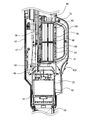
- the battery side exhaust passage 74 is a flow path that allows the exhaust air flowing from the electric blower unit 40 side to pass downstream from the location where the battery pack 60 is provided. As shown by an arrow in FIG. 4, the air flow flowing from the electric blower unit 40 side can pass through the battery side exhaust passage 74.
- the air flow discharged from the battery side exhaust passage 74 is discharged from the main body exhaust port 14 or the like provided on the side surface of the vacuum cleaner main body 10. Since such an air flow is formed around the battery pack 60, the effect of suppressing the temperature rise and the effect of cooling the battery pack 60 can be expected. Further, as shown in FIG.
- the circuit board 15 is arranged on the outer peripheral surface (front side in the present embodiment) of the battery pack storage unit 24. Therefore, the exhaust air (air flow) flowing outside the battery pack storage unit 24 can be expected to have a temperature rise suppressing effect and a cooling effect of the circuit board 15. Further, the exhaust air flowing outside the battery pack storage portion 24 is exhausted from the main body exhaust port 14 after passing through the circuit board 15.
- the first handle 80 is provided on the side of the main body case 12 of the vacuum cleaner main body 10 opposite to the side to which the dust collecting portion 20 is connected (the side serving as the suction port). There is.
- the first handle 80 is removable from the vacuum cleaner body 10.
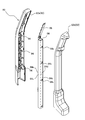
- the first handle 80 includes a handle case 82, a pipe member 84, and a first operation unit 86.
- the handle case 82 is a portion forming the outer shape of the first handle 80, and is elongated and hollow.
- the handle case 82 is configured by combining a front-side handle component 82a and a back-side handle component 82b.
- the front handle component 82a and the back handle 82b form portions facing the front side and the back side when the first handle 80 is attached to the vacuum cleaner body 10, respectively.
- the handle case 82 includes a first handle case portion 90 and a second handle case portion 92.
- the first handle case portion 90 is a portion that is connected to the vacuum cleaner main body 10 and extends in the axial direction of the vacuum cleaner main body 10.
- the second handle case portion 92 is formed so as to be continuous with the first handle case portion 90 and extend in a direction intersecting with the first handle case portion 90 (direction toward the back side of the vacuum cleaner main body 10). Has been done. That is, the handle case 82 is bent at the boundary portion between the first handle case portion 90 and the second handle case portion 92.
- the end surface of the first handle case portion 90 on the base end side is a first handle connection portion 28 provided in the main body case 12 of the vacuum cleaner main body 10.
- the shape is inclined or curved according to the shape of the end face to be formed (in the present embodiment, the shape is inclined).
- the handle case 82 has a handle boss portion 94 (boss portion) that protrudes inward.
- the handle boss portion 94 can be provided on either one or both of the front side handle constituent portion 82a and the back side handle constituent portion 82b, but in the present embodiment, the handle boss portion 94 is provided on the front side handle constituent portion 82a.
- the pipe member 84 is housed inside the handle case 82.
- the pipe member 84 may be housed in only one of the first handle case portion 90 and the second handle case portion 92, but in the present embodiment, the pipe member 84 is housed in the first handle case portion 90. It is housed in, and is not housed in the second handle case portion 92.
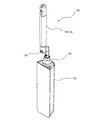
- the pipe member 84 can have an appropriate shape such as a cylindrical pipe or a square pipe, but in the present embodiment, a square pipe having a substantially square cross-sectional shape is adopted. Further, as the material of the pipe member 84, resin, stainless steel or aluminum can be used as shown in FIG.
- the pipe member 84 is provided on the front portion 84a facing the front side of the vacuum cleaner main body 10, the back portion 84b facing the back side of the vacuum cleaner main body 10, and the left and right side surface sides of the vacuum cleaner main body 10. It has side surface portions 84c and 84d facing each other.
- the pipe member 84 is erected in a direction in which the side surface portions 84c and 84d intersect with the front surface portion 84a and the back surface portion 84b. Therefore, when the pipe member 84 is cleaned by holding the first handle 80, when stress from the front side and the back side acts on the front portion 84a and the back portion 84b, this stress is applied to the side surface portion 84c, The effect of supporting at 84d can be expected.
- the pipe member 84 is a square pipe, aluminum is preferable to stainless steel because it is lightweight.
- the pipe member 84 is formed with a plurality of through holes 84x in the longitudinal direction.
- the through hole 84x is provided at a position corresponding to the handle boss portion 94 provided in the handle case 82.
- a plurality of through holes 84x are provided in the front portion 84a of the pipe member 84 so as to be arranged in the longitudinal direction of the pipe member 84. Therefore, when the pipe member 84 is incorporated into the handle case 82, the pipe member 84 is engaged with the handle case 82 by inserting the handle boss portion 94 into the through hole 84x with the front portion 84a facing the front side. On the other hand, it can be fixed so as not to be displaced in the longitudinal direction and the circumferential direction.
- the pipe member 84 is fixed so that a protruding portion 96 protruding from the end portion of the handle case 82 on the first handle case portion 90 side by a predetermined amount is formed.
- the protruding portion 96 is a portion that is inserted into and accommodated in the accommodating portion 30 of the first handle connecting portion 28 provided at the end of the main body case 12 described above.
- an engaged portion 98 is provided on the peripheral portion (front portion 84a in the present embodiment) of the protruding portion 96.
- the engaged portion 98 is a portion where the tip portion 34a of the engaging portion 34 provided on the main body case 12 side engages when the protruding portion 96 is inserted into the accommodating portion 30.
- the first operation unit 86 is provided on the second handle case unit 92, which is assumed to be mainly gripped by the user in the first handle 80.
- the first operation unit 86 is provided with a switch or the like for performing an operation such as turning on / off the power of the vacuum cleaner 1, for example.
- the second handle 100 is a handle provided on the back side of the vacuum cleaner main body 10.
- the second handle 100 is provided with a second operation unit 102.
- the second operation unit 102 is provided with a switch or the like for performing an operation such as turning on / off the power of the vacuum cleaner 1, for example.
- the electric vacuum cleaner 1 can be used even when the first handle 80 is removed from the vacuum cleaner main body 10.
- the auxiliary dust collecting unit 120 is provided on the outer peripheral portion of the main body case 12 of the vacuum cleaner main body 10.
- the auxiliary dust collecting unit 120 is provided on the left side surface or the right side surface of the main body case 12.
- the auxiliary dust collecting unit 120 is for collecting dust by a method different from the dust collecting by the suction force generated by the operation of the electric blower unit 40.
- the auxiliary dust collector 120 is provided with a mop as the auxiliary dust collector 122.
- the auxiliary dust collector 120 includes an auxiliary dust collector 122 and an auxiliary dust collector accommodating unit 124.
- the auxiliary dust collector 120 accommodates the auxiliary dust collector 122 in the auxiliary dust collector storage unit 124 attached to the main body case 12, and the user appropriately takes out and uses the auxiliary dust collector 122. It is possible.
- the auxiliary dust collector accommodating portion 124 is a tubular member having a bottom and an opening on the upper end side.
- the auxiliary dust collector accommodating portion 124 can be selectively attached so as to close one of the main body exhaust ports 14 and 14 provided on the left side surface and the right side surface of the vacuum cleaner main body 10. Therefore, the exhaust gas discharged from the inside of the main body case 12 is discharged from the main body exhaust port 14 on the side opposite to the side to which the auxiliary dust collector accommodating portion 124 is attached by attaching the auxiliary dust collector accommodating portion 124.
- the auxiliary dust collector accommodating portion 124 functions as a member for opening and closing one of the main body exhaust ports 14 and 14 provided at a plurality of places (two places in the present embodiment) in the vacuum cleaner main body 10. be able to.
- the auxiliary dust collector accommodating portion 124 can function as a member for selecting the discharge direction of the exhaust gas discharged from the vacuum cleaner main body 10.
- the auxiliary dust collector 122 is composed of a mop as described above.
- the auxiliary dust collector 122 is provided with a grip portion 126.
- the grip portion 126 has an exposed portion 128 that protrudes (exposed) to the outside in a state where the auxiliary dust collector 122 is housed in the auxiliary dust collector accommodating portion 124.
- the grip portion 126 has a shape along the side surface of the vacuum cleaner main body 10 in a state of being accommodated in the auxiliary dust collector accommodating portion 124.
- the exposed portion 128 is provided with a second fixing portion 130.
- the second fixing portion 130 is capable of being connected (fixed) to the first fixing portion 16 provided on the side surface of the vacuum cleaner main body 10.
- first fixing portion 16 and the second fixing portion 130 may be magnets, one may be a magnet, and the other may be a metal having a ferromagnet.
- the first fixing portion 16 is provided at a position where the second fixing portion 130 arrives in a state where the auxiliary dust collector 122 is housed in the auxiliary dust collector accommodating portion 124. Therefore, by connecting the first fixing portion 16 and the second fixing portion 130, the grip portion 126 can be positioned and fixed in a state where the auxiliary dust collector 122 is housed in the auxiliary dust collector accommodating portion 124.
- the suction unit 140 includes a suction unit main body 142, a joint portion 144, a cleaning body 146, and a cleaning body driving mechanism 148.
- the suction portion 140 can be connected to the vacuum cleaner main body 10 by connecting the joint portion 144 to the dust collecting portion 20 side of the vacuum cleaner main body 10.
- the suction portion 140 has a suction space in which the suction portion main body 142 opens toward the floor surface side, and the cleaning body 146 is rotatably supported inside the suction space.
- the cleaning body 146 has a cleaning body main body 150 extending in the longitudinal direction (left-right direction) of the suction portion main body 142, and a mounting portion 152.
- the cleaning body body 150 is assumed to have a brush mounting portion 154 provided on the outside of the cleaning body body 150 formed in a tubular shape, and a groove portion 156 provided between the brush mounting portions 154 and 154 adjacent in the circumferential direction.
- the brush mounting portion 154 and the groove portion 156 can be, for example, provided substantially linearly in the axial direction of the cleaning body main body 150, respectively, but in the present embodiment, the axial center position of the cleaning body main body 150 is the center. As a result, it is provided so as to draw a spiral on the outer circumference of the cleaning body body 150.
- the brush mounting portion 154 has a rail shape, and the brush 158 can be sandwiched and held in a state of protruding toward the outside of the cleaning body body 150.
- the mounting portion 152 is a portion used for mounting the cleaning body 146 to the suction portion main body 142.
- the mounting portion 152 is provided on one side and the other side in the longitudinal direction of the cleaning body main body 150.
- the attachment portion 152 is a portion that is attached to the support portion 172 on the suction portion main body 142 side, which will be described in detail later.
- the mounting portion 152 includes a mounting recess 160 (see FIG. 15), a groove 162, and a step portion 164.
- the mounting recess 160 is formed in a concave shape on the end surface of the mounting portion 152.
- the mounting recess 160 is a portion that fits into and engages with the mounting protrusion 174 provided on the support portion 172 on the suction portion main body 142 side.
- the groove 162 is provided in the middle portion of the mounting portion 152. Specifically, the groove 162 is a portion of the cleaning body 146 that is supported by the support portion 172 on the suction portion main body 142 side (the end portion of the attachment portion 152 in this embodiment) and the brush attachment portion 154 to which the brush 158 is attached. It is located between and. The groove 162 is provided over substantially the entire circumference of the mounting portion 152.
- the step portion 164 is provided at a position biased toward a portion further supported by the support portion 172 with respect to the groove 162 (the end portion of the mounting portion 152 in the present embodiment).
- the step portion 164 is a portion where a step is formed by increasing the diameter on the end side of the cleaning body 146.
- the step portion 164 is engaged with the step engaging portion 170 provided on the suction portion main body 142 side.
- the step portion 170 engages with the step portion 164 so as to cover the step portion 164.
- the suction portion main body 142 is provided with support portions 172 to be attached to the attachment portions 152 provided at both ends of the cleaning body 146.
- the support portion 172 is rotatably supported with respect to the suction portion main body 142.
- the end face of the support portion 172 can be brought into surface contact with the end face of the mounting portion 152.
- the end surface of the support portion 172 has a mounting convex portion 174 (see FIG. 15) at a position corresponding to the mounting recess 160 of the mounting portion 152.
- the mounting portion 152 can be attached to the supporting portion 172 by fitting the mounting concave portion 160 into the mounting convex portion 174 and connecting the support portion 172 and the mounting portion 152 in surface contact with each other on the end faces of both. ..
- the cleaning body 146 is rotatably supported inside the suction portion main body 142.
- a cleaning body driving mechanism 148 is connected to one side so as to be able to transmit power. Therefore, the cleaning body 146 can be driven by receiving the power output from the cleaning body driving mechanism 148.
- the cleaning body drive mechanism 148 includes a drive machine 180, a power transmission body 182, an output side pulley 184, a driven side pulley 186, and the like.
- the drive machine 180 is composed of a motor or the like provided in the suction unit main body 142. Further, the power transmission body 182 is composed of an endless belt with teeth. Further, the output side pulley 184 is a toothed pulley attached to the output shaft of the motor forming the drive machine 180. Further, the driven side pulley 186 is integrally provided on the support portion 172 to be connected to the cleaning body drive mechanism 148.
- the cleaning body drive mechanism 148 is configured such that the power transmission body 182 is hung around the power transmission body 182 made of an endless belt between the output side pulley 184 and the driven side pulley 186. Therefore, by operating the drive machine 180, the rotational power can be transmitted to the mounting portion 152b side, and the cleaning body 146 can be rotationally driven in the suction space of the suction portion main body 142.
- a plate-shaped member 64 is inserted between the electric blower unit 40 (electric blower 42) and the battery pack 60 inside the main body case 12. Can be provided.
- the plate-shaped member 64 can also be provided as a part of the main body case 12 or a part of the battery pack 60.
- the plate-shaped member 64 is a plate-shaped member extending in a direction intersecting the axial direction of the electric blower 42.
- the plate-shaped member 64 is arranged substantially parallel to the wind receiving portion 46a of the cover body 46 forming the electric blower unit 40.
- the plate-shaped member 64 suppresses the liquid or the like from entering the inside of the battery pack storage portion 24 when a foreign substance such as a liquid spilled on the floor is sucked, and the battery pack 60 It can function as an obstacle plate to protect the battery.
- the configuration of the vacuum cleaner 1 can be appropriately changed instead of providing the plate-shaped member 64 as described above.
- the cover body instead of providing the cover body 46 in the electric blower unit 40 described above, the cover body is provided by providing a boss portion 25 on the end face on the upstream side in the air flow direction in the battery pack storage portion 24.
- a configuration in which 46 is attached may be used. According to such a configuration, it is possible to make the cover body 46 exert a substitute function of the plate-shaped member 64 while ensuring the function as the cover body 46 in the electric blower unit 40 described above. As a result, it is possible to exert the noise suppression effect in the electric blower unit 40, the effect as an obstacle plate against foreign substances such as liquid spilled on the floor, and the like while suppressing the number of parts to the minimum.
- the upstream side opening 24a and the downstream side opening 24b are provided in the upstream side and the downstream side of the air flow in the battery pack storage portion 24, while the battery pack 60 is provided with an opening.
- the configuration can be changed as appropriate.
- the inflow side opening 70 and the discharge side opening 72 are provided on one end side and the other end side in the longitudinal direction of the battery pack 60.
- the inflow side opening 70 and the discharge side opening 72 may also have appropriate ones such as a round hole and a slit-shaped hole.
- the battery case 66 is arranged so that the inflow side opening 70 faces the electric blower unit 40 side.
- the inflow side opening 70 is a portion opened so that the exhaust gas discharged from the electric blower unit 40 (electric blower 42) can flow into the inside of the battery case 66.
- the discharge side opening 72 is a portion opened so that exhaust gas can be discharged from the inside of the battery case 66 to the outside.
- the air flow is to flow inside the battery case 66
- a plurality of batteries 68 are arranged inside the battery case 66 along the direction (longitudinal direction) from the inflow side opening 70 to the discharge side opening 72.
- the batteries 68 are spaced apart from each other in the battery case 66 in a direction intersecting the direction from the inflow side opening 70 toward the discharge side opening 72 (in the present embodiment, a direction substantially orthogonal to each other (width direction)). Are lined up open.
- an air flow can smoothly flow in the direction from the inflow side opening 70 to the discharge side opening 72 between the batteries 68 arranged in the width direction. Further, in such a configuration, the air (exhaust) is also discharged to the position adjacent to the battery pack storage portion 24 and the battery pack 60 on the downstream side in the flow direction of the air flow in the first handle connection portion 28. It is preferable to provide an opening (exhaust opening) for the purpose. With such a configuration, the downstream side opening 24b and the discharge side opening 72 and the exhaust opening provided in the first handle connecting portion 28 are in a facing relationship, so that the exhaust becomes smoother.
- the position facing the main body exhaust port 14 provided on the side of the main body case 12 or in the vicinity thereof. may be provided. Even with such a configuration, exhaust from the vicinity of the battery pack 60 to the outside becomes smoother.
- the battery pack storage portion 24 is provided with the upstream side opening 24a and the downstream side opening 24b, and the battery pack 60 is provided with the inflow side opening 70 and the discharge side.
- the openings 72 are provided, the vacuum cleaner 1 may not have these openings.
- the cover body 46 is fixed to the electric blower case 44 of the electric blower unit 40 as described above, or is fixed to the end face on the upstream side in the air flow direction in the battery pack storage portion 24. It may be installed by a configuration other than the above. For example, as shown in FIG. 19, by installing the electric blower case 44 inside the main body case 12 via a vibration-proof member 45 such as rubber, vibration is transmitted from the electric blower case 44 side to the main body case 12 side. May try to suppress.
- the cover body 46 is arranged so that the anti-vibration member 45 comes into contact with the back surface side of the wind receiving portion 46a, and the same anti-vibration member 45 as the anti-vibration member 45 is provided on the front surface side of the wind receiving portion 46a.
- the vibration-proof member 47 is provided, and the vibration-proof member 47 is sandwiched and installed inside the main body case 12 by ribs 12x protruding from the outside in the radial direction to the inside.
- the anti-vibration members 45 and 47 may be integrated instead of a separate body so as to penetrate the cover body 46, and the integrated anti-vibration members 45 and 47 may be fixed to the electric blower case 44. With such a configuration, the cover body 46 can be installed while suppressing the transmission of vibration from the electric blower case 44 side to the main body case 12 side.
- the vacuum cleaner 1 of the present embodiment has a dust collecting unit 20 that collects dust, an electric blower 42 that generates an air flow for sucking dust, and an exhaust side of the electric blower 42.
- the cover body 46 provided apart from the electric blower 42 and the exhaust air provided on the exhaust side of the cover body 46 and exhausting the exhaust air generated by the electric blower 42 from between the electric blower 42 and the cover body 46.
- the cover body 46 includes a port 52c, and the cover body 46 includes a wind direction guide portion 46c that guides the wind direction of the exhaust air discharged from the exhaust port 52c to the suction side of the electric blower 42.
- the electric vacuum cleaner 1 of the present embodiment has low noise due to the operation of the electric blower 42.
- the electric blower 42 is housed, and the intake opening 47 located on the suction side of the electric blower 42 and the exhaust opening 48 located on the exhaust side of the electric blower 42. It is provided with an electric blower case 44 having the above, and a boss portion 50 (fixing member) for fixing the cover body 46 to the electric blower case 44.
- the vacuum cleaner 1 can fix the cover body 46 to the electric blower case 44 in a state of being separated by a predetermined distance.
- a blower exhaust passage 52 through which exhaust gas can pass can be sufficiently secured between the cover body 46 and the electric blower case 44.
- the boss portion 50 is used as a fixing member is shown, but the present invention is not limited to this, and another member may be used as a fixing member as long as it can be integrally fixed.
- the cover body 46 is provided with the first sound absorbing material 56a.
- the vacuum cleaner 1 can suppress the generation of noise due to the exhaust gas colliding with the cover body 46.
- the first sound absorbing material 56a is provided on the cover body 46 is shown, but the present invention is not limited to this, and the first sound absorbing material 56a may not be provided.
- the vacuum cleaner 1 includes a main body case 12 that houses at least the electric blower 42 and the electric blower case 44, and is formed inside the main body case 12 between the electric blower case 44 and the cover body 46. It is assumed that the second sound absorbing material 56b is provided at the tip in the direction of the flow path to be formed.
- the vacuum cleaner 1 Due to this configuration, the vacuum cleaner 1 generates noise due to the exhaust gas discharged from the blower exhaust passage 52 formed between the electric blower case 44 and the cover body 46 colliding with the main body case 12. Can be minimized.
- the vacuum cleaner 1 may be configured not to be provided with the second sound absorbing material 56b.
- the cover body 46 has a wind receiving portion 46a that receives the exhaust gas of the electric blower 42, and the wind direction guide portion 46c is on the downstream side in the exhaust flow direction with respect to the wind receiving portion 46a. It is said to be the configuration in.
- the vacuum cleaner 1 may not be provided with the wind direction guide portion 46c.
- the cover body 46 has a wind receiving portion 46a that receives the exhaust of the electric blower 42, and the first sound absorbing material 56a is provided in the wind receiving portion 46a. There is.
- the first sound absorbing material 56a may be provided in a portion of the cover body 46 other than the wind receiving portion 46a.
- the vacuum cleaner 1 of the present embodiment discharges the dust collecting unit 20 for collecting dust, the electric blower 42 for generating an air flow for sucking the dust, and the air flow generated by the electric blower 42 to the outside.
- the battery side exhaust passage 74 through which the wind passes is configured.
- the temperature rise around the battery pack 60 can be suppressed by the air flow flowing through the battery side exhaust passage 74, and the heat dissipation effect of the battery pack 60 can be improved.
- the battery pack 60 includes the battery case 66 and the battery 68 provided inside the battery case 66, and the exhaust air from the electric blower 42 flows into the battery case 66.
- the inflow side opening 70 and the discharge side opening 72 in which the exhaust air is discharged from the inside of the battery case 62 to the outside are included.
- the inflow side opening 70 and the discharge side opening 72 are provided in the battery case 66, but the inflow side opening 70 and the discharge side opening 72 may not be provided.
- the batteries 68 are arranged in the direction from the inflow side opening 70 to the discharge side opening 72.
- an air flow can flow along the battery 68, and the cooling effect can be further improved.
- the configuration in which the batteries 68 are arranged along the direction from the inflow side opening 70 to the discharge side opening 72 is illustrated, but the vacuum cleaner 1 has a different arrangement from the batteries 66. May be provided.
- the batteries 68 are arranged at predetermined intervals in the direction intersecting the direction from the inflow side opening 70 toward the discharge side opening 72. ..
- an air flow can be generated between the batteries 68 arranged in parallel, and the cooling efficiency of the batteries 66 can be further improved.
- the batteries 66 may be arranged in a plurality of rows without gaps.
- the batteries 66 may be provided in only one row in the direction from the inflow side opening 70 to the discharge side opening 72.
- the vacuum cleaner 1 is provided with a plate-shaped member 64 extending in a direction intersecting the axial direction of the electric blower 42 between the electric blower 42 and the battery pack 60.
- the present invention is not limited to this, and the plate-shaped member 64 may not be provided. Further, instead of omitting the plate-shaped member 64 by letting the cover body 46 play the role of the plate-shaped member 64, or providing the cover body 46 on the electric blower unit 40 side, the upstream side of the exhaust flow direction in the battery pack 60.
- a cover body 46 may be provided at the position of (see FIG. 17).
- the vacuum cleaner 1 contains an electric blower 42, and has an electric blower case 44 having an intake opening 47 located on the suction side of the electric blower 42 and an exhaust opening 48 located on the exhaust side of the electric blower 42.
- a plate-shaped member 64 projecting inward from the inside of the main body case 12 may be provided on the exhaust side of the electric blower case 44.
- the plate-shaped member 64 can play the role of the cover body 46 in the above embodiment.
- the vacuum cleaner 1 may have the cover body 46 omitted or the like.
- the vacuum cleaner 1 of the present embodiment has a vacuum cleaner main body 10 having an electric blower 42, a handle case 82 attached to the vacuum cleaner main body 10, and a protruding portion 96 partially protruding from one end of the handle case 82.
- the pipe member 84 is housed inside the handle case 82, and the vacuum cleaner main body 10 is provided with a house 30 in which the projecting portion 96 is housed without being exposed.
- the handle case 82 can be firmly integrated with the vacuum cleaner main body 10. Therefore, according to the above-described configuration, even if the weight of the vacuum cleaner main body 10 is increased by using a high-power electric blower unit 40, for example, the strength of the handle case 82 and the handle case 82 Sufficient connection strength with the vacuum cleaner main body 10 can be secured.
- the vacuum cleaner 1 is provided on the engaging portion 34 that engages with the pipe member 84 on the vacuum cleaner main body 10 side, and the engaged portion 98 that is provided on the protruding portion 96 and that the engaging portion 34 engages. And have.
- the handle case 82 and the vacuum cleaner main body 10 can be firmly connected by the engaging structure formed by the engaging portion 34 and the engaged portion 98. Further, if the engaging portion 34 is fixed to the protruding portion 96 at a predetermined position in the circumferential direction of the pipe member 84, the pipe member 84 can be positioned at a predetermined position in the circumferential direction. Thereby, the positioning accuracy of the handle case 82 can be improved.
- the handle case 82 and the vacuum cleaner main body 10 are connected by the engaging portion 34 and the engaged portion 98 is shown, but the present invention is not limited to this, and other It may be connected by a connecting method or the like.
- the handle case 82 has a handle boss portion 94 protruding inward, and the pipe member 84 has a through hole 84x penetrating in a direction intersecting the axial direction. Then, the pipe member 84 is fixed to the handle case 82 by inserting the handle boss portion 94 into the through hole 84x.
- the pipe member 84 can be fixed to the handle case 82 with high positioning accuracy.
- the pipe member 84 is positioned and fixed to the handle case 82 by using the handle boss portion 94, but the handle boss portion 94 and the through hole 84x may not be provided.
- the above-mentioned vacuum cleaner 1 has a engaging / disengaging portion protruding or retracting in the axial direction of the pipe member 84 on either one or both of the handle case 82 and the vacuum cleaner main body 10, and the handle case 82 and cleaning One or both of the machine main body 10 may be provided with an engaged / disengaged portion capable of engaging / disengaging.
- the handle case 82 can be fixed to the vacuum cleaner main body 10 so as not to rotate due to the engagement / disengagement structure formed by the engagement / disengagement portion and the engagement / disengagement portion. Further, as shown in FIGS.
- a handle connecting protrusion 31 protruding from the first handle connecting portion 28 is provided integrally or separately from the main body case 12, while a handle connecting portion is provided at the lower end on the first handle 80 side.
- a handle connection receiving portion 80a (not shown) having a recess into which the protrusion 31 can be inserted is provided, and an insertion portion 31a communicating with the accommodating portion 30 is provided in the handle connection protrusion 31 with respect to the insertion portion 31a.
- the protruding portion 96 of the pipe member agent 84 may be inserted.
- a fitting structure formed by the handle connecting protrusion 31 and the handle connecting receiving portion 80a (for example, rectangular cross sections), and a fitting composed of the insertion portion 31a and the protruding portion 96. Due to the combined structure, the first handle portion 80 can be fixed to the vacuum cleaner main body 10 so as not to rotate.
- the electric vacuum cleaner 1 is inclined or curved so that a part or all of the end faces of the handle case 82 connected to the vacuum cleaner main body 10 intersect with each other in the axial direction of the pipe member 84.
- the shape is such that a part or all of the end face of the vacuum cleaner main body 10 on the side connected to the handle case 82 is inclined or curved according to the end face of the handle case 82.
- the vacuum cleaner 1 can be connected with the handle case 82 positioned at a predetermined position with respect to the vacuum cleaner main body 10.
- the present invention is not limited to this, and the handle case 82 and the vacuum cleaner body 10 are not limited to this. Only a part of the end faces of either one or both may be inclined, or the end faces of either one or both of the handle case 82 and the vacuum cleaner main body 10 may be bent into a wavy shape or the like.
- the handle case 82 has a front-side handle component 82a facing the front side of the vacuum cleaner body 10 and a back-side handle component 82b facing the back side of the vacuum cleaner body 10. It is configured by combining the front side handle configuration portion 82a and the back side handle configuration portion 82b, and the handle boss portion 94 is either the front side handle configuration portion 82a or the back side handle configuration portion 82b. It is supposed to be provided on one or both sides.
- the vacuum cleaner 1 can position and fix the pipe member 84 with respect to the handle case 82 by using the handle boss portion 94.
- the handle boss portion 94 is provided on the front side handle configuration portion 82a side, but instead of this, the vacuum cleaner 1 has the handle boss portion 94 on the rear side handle configuration portion 82b side.
- a handle boss portion 94 may be provided on both the front side handle configuration portion 82a and the back side handle configuration portion 82b.
- the electric vacuum cleaner 1 may be provided with a handle boss portion 94 on both the front side handle constituent portion 82a and the rear side handle constituent portion 82b.
- the handle case 82 is connected to the vacuum cleaner main body 10 and extends to the first handle case portion 90 and the first handle case portion 90 extending in the axial direction of the vacuum cleaner main body 10. It has a second handle case portion 92 that is continuous and extends in a direction intersecting the first handle case portion 90, and the pipe member 84 is housed in at least the first handle case portion 90.
- the electric vacuum cleaner 1 has a high strength of the first handle case portion 90 connected to the vacuum cleaner main body 10 in the handle case 82. Therefore, even if the weight of the vacuum cleaner main body 10 becomes large by using a high-power electric vacuum cleaner unit 40, for example, the electric vacuum cleaner 1 is a connection portion between the handle case 82 and the vacuum cleaner main body 10. It is possible to secure sufficient strength even in the above.
- a configuration in which the pipe member 84 is built in the first handle case portion 90 of the handle case 82 and the pipe member 84 is not built in the second handle case portion 92 is illustrated, but the present invention illustrates this.
- the method is not limited, and for example, a pipe member 84 that is bent in the same manner as the handle case 82 is used to incorporate the pipe member 84 in the second handle case portion 92, or the pipe member is also incorporated in the second handle case portion 82.
- the same thing as 84 may be built in.
- the pipe member 84 has a front portion 84a facing the front side of the vacuum cleaner main body 10, a back portion 84b facing the back side of the vacuum cleaner main body 10, and a side surface of the vacuum cleaner main body 10. It has side surface portions 84c and 84d facing sideways, and is erected in a direction in which the side surface portions 84c and 84d intersect with the front surface portion 84a and the back surface portion 84b.
- the vacuum cleaner 1 of the present embodiment includes a vacuum cleaner main body 10 having an electric blower 42 and a detachable first handle 80 provided on the side of the vacuum cleaner main body 10 opposite to the suction portion 140.
- the vacuum cleaner main body 10 is provided with a second handle 100 provided on the peripheral surface of the vacuum cleaner main body 10.
- the vacuum cleaner 1 can be used not only in the form of using the first handle 80 but also in the form of using the second handle 100.
- the vacuum cleaner 1 illustrated in the present embodiment is provided with both the first handle 80 and the second handle 100, but one provided with only one of these, and yet another handle. It may be the one provided with.
- the vacuum cleaner 1 is provided on the first handle 80, and is provided on at least one of the first operation unit 86 for instructing the drive of the electric blower 42, the second handle 100, and the vacuum cleaner main body 10. It is said that the electric blower 42 is provided with a second operation unit 102 for instructing the drive of the electric blower 42.
- the vacuum cleaner 1 is easy to operate regardless of whether it is used with the first handle 80 or the second handle 100.
- the first operation unit 86 and the second operation unit 102 are provided corresponding to both the first handle 80 and the second handle 100
- the present invention is limited thereto. It's not a thing.
- the vacuum cleaner 1 does not include either the first operation unit 86 or the second operation unit 102, or is provided with another operation unit in place of the first operation unit 86 and the second operation unit 102. It may be a new one.
- the second handle 100 is provided on the back side of the vacuum cleaner main body 10.
- the second handle 100 is arranged at a position where it does not get in the way, and if necessary, the second handle 100 It is possible to provide an easy-to-use vacuum cleaner 1 that can be used by holding the handle 100.
- the present invention is not limited to this, for example, other surfaces of the vacuum cleaner main body 10 and the like. It may be provided in.
- the vacuum cleaner 1 is capable of collecting dust when the first handle 80 is removed from the vacuum cleaner main body 10.
- the vacuum cleaner 1 can be used as a short one by removing the first handle 80. Therefore, the vacuum cleaner 1 can be suitably used for applications such as cleaning the inside of an automobile, bringing it into a narrow place, and using it.
- the vacuum cleaner 1 a vacuum cleaner 1 that can be used even if the first handle 80 is removed from the vacuum cleaner main body 10 is illustrated, but the present invention is not limited to this. It may be something that cannot be used when the first handle 80 is removed.
- the vacuum cleaner 1 of the present embodiment cleans the vacuum cleaner main body 10 having the electric blower 42, the auxiliary dust collector accommodating portion 124 capable of accommodating the auxiliary dust collector 122, and the air flow generated by the electric blower 42.
- the main body exhaust port 14 for discharging to the outside of the machine main body 10 is provided, and the main body exhaust port 14 is provided on the left side surface and the right side surface of the vacuum cleaner main body 10, respectively, and the auxiliary dust collector accommodating portion 124 is provided. It is characterized in that it can be selectively attached so as to close one of the main body exhaust port 14 on the left side surface and the main body exhaust port 14 on the right side side.
- the auxiliary dust collector 122 can be deployed to the vacuum cleaner main body 10 in a convenient state. Further, according to the above-described configuration, the auxiliary dust collector accommodating portion 124 closes either the main body exhaust port 14 on the left side surface or the main body exhaust port 14 on the right side surface, so that the user can collect auxiliary dust.
- the dust tool 122 can be arranged in a place where it is easy to put in and take out, and it is possible to arbitrarily select at which position the main body exhaust port 14 is provided in the vacuum cleaner main body 10. Therefore, in the vacuum cleaner 1, for example, the auxiliary dust collector 122 is arranged on the side of the user to improve the usability of the auxiliary dust collector 122, and the exhaust gas is discharged from the side opposite to the user. It is possible to suppress the discomfort caused by the user being exposed to the exhaust gas.
- the vacuum cleaner 1 has an auxiliary dust collector 122 housed in the auxiliary dust collector accommodating unit 124, and the auxiliary dust collector 122 is housed in the auxiliary dust collector accommodating unit 124.
- the shape is along the side surface of the vacuum cleaner body 10.
- the vacuum cleaner 1 can be arranged so that the auxiliary dust collector 122 does not interfere with the user.
- the auxiliary dust collector 122 has a shape along the side surface of the vacuum cleaner main body 10 in the state of being housed in the auxiliary dust collector accommodating portion 124.
- the shape is not limited, and the shape may not be such a shape.
- the vacuum cleaner 1 has an auxiliary dust collector 122 housed in the auxiliary dust collector accommodating unit 124, and the auxiliary dust collector 122 is housed in the auxiliary dust collector accommodating unit 124. It has an exposed portion 128 exposed to the outside, and the second fixing portion 130 provided on the exposed portion 128 can be fixed to the first fixing portion 16 provided on the vacuum cleaner main body 10 side. ..
- the auxiliary dust collector 122 can be suppressed from becoming an obstacle when using the vacuum cleaner 1.
- the auxiliary dust collector 122 is fixed at a predetermined position by fixing the exposed portion 128 of the auxiliary dust collector 122, but the present invention is not limited to this.
- the vacuum cleaner 1 does not provide a means for fixing the auxiliary dust collector 122 from a predetermined position or fixing the auxiliary dust collector 122 by fixing a portion other than the exposed portion 128. You may decide.
- either one or both of the first fixing portion 16 and the second fixing portion 130 are composed of magnets.
- Both the first fixing portion 16 and the second fixing portion 130 may be composed of magnets, or one may be a magnet and the other may be a ferromagnet. Further, both the first fixing portion 16 and the second fixing portion 130 may be formed of something other than a magnet.
- the vacuum cleaner 1 of the present embodiment has a vacuum cleaner main body 10 having an electric blower 42 and a suction portion 140 connected so as to communicate with the vacuum cleaner main body 10.
- the 140 rotates the suction part main body 142 having a space open to the outside, the cleaning body 146 with the brush 158 attached to the peripheral portion of the cleaning body main body 150, and the end of the cleaning body 146 inside the space.
- It has a support portion 172 that freely supports it, and in the cleaning body 146, a groove 162 extending in the circumferential direction of the cleaning body main body 150 is provided between a portion where the brush 158 is mounted and a portion supported by the support portion 172. It is formed, and is characterized in that a step portion 164 is further provided on the support portion 172 side with respect to the groove 162.
- the vacuum cleaner 1 Since the vacuum cleaner 1 is provided with the groove 162 as described above, even if hair, lint, etc. are entangled in the cleaning body 146, the hair or lint is first caught in the groove 162, and the hair or the like is further on the support portion 172 side. Can be suppressed from getting entangled. Further, the vacuum cleaner 1 has a step portion 164 on the support portion 172 side in addition to the groove 162. Due to the presence of the step portion 164, the vacuum cleaner 1 has a step portion so that even if hair or the like crosses the groove 162 and invades the support portion 172 side, the hair or the like does not invade the support portion 172 side. It can be protected by unit 164. Therefore, in the vacuum cleaner 1, the suction portion 140 is less likely to have hair or the like invading the support portion 172 side, and it is easy to maintain a clean state.
- the vacuum cleaner 1 is supposed to have a step engaging portion 170 that engages so as to cover the step portion 164.
- the vacuum cleaner 1 can protect the step portion 164 from the entanglement of hair and the like by the step engaging portion 170.
- the vacuum cleaner 1 of the present embodiment is provided with the step engaging portion 170, but the present invention is not limited to this, and the vacuum cleaner 1 is not provided with the step engaging portion 170. Is also good.
- the electric vacuum cleaner 1 has a cleaning body driving mechanism 148 that applies rotational power to the cleaning body 146, and the cleaning body driving mechanism 148 is an end portion of the cleaning body main body 150 rather than a step portion 164. It is connected so that power can be transmitted on the side.
- the vacuum cleaner 1 is less likely to be entangled with hair, lint, etc. to the cleaning body drive mechanism 148, or to malfunction or malfunction due to intrusion.
- the suction unit 140 is provided with the cleaning body drive mechanism 148, but the present invention is not limited to this, and the suction unit 140 is the cleaning body drive mechanism 148 and the like. It may not be provided with a drive source of.
- the cleaning body driving mechanism 148 has a power transmitting body 182 that transmits the power output from the power source to the cleaning body main body 150, and the power transmitting body 182 has a step. It is said that the cleaning body body 150 is suspended so that power can be transmitted on the end side of the cleaning body body 150 rather than the portion 164.
- the vacuum cleaner 1 is unlikely to be entangled with hair or lint to the power transmitter 182, or to malfunction or malfunction due to intrusion.
- a belt-shaped power transmission body 182 is shown, but the present invention is not limited to this, and the power transmission body 182 is composed of other members. Is also good.
- the vacuum cleaner according to the first aspect of the present embodiment has a dust collecting unit that collects dust, an electric blower that generates an air flow for sucking dust, and an exhaust side of the electric blower.
- the cover body is provided with a cover body provided in a state of being separated from the electric blower, and an exhaust port provided on the exhaust side of the cover body and exhausting the exhaust air generated by the electric blower to the outside. Is characterized by including a wind direction guiding portion that guides the wind direction of the exhaust air to the suction side of the electric blower.
- the above-mentioned electric vacuum cleaner is an electric blower in which the electric blower is housed and has an intake opening located on the suction side of the electric blower and an exhaust opening located on the exhaust side of the electric blower. It is preferable that the case and the fixing member for fixing the cover body to the electric blower case are provided.
- the above-mentioned vacuum cleaner is preferably characterized in that the cover body is provided with the first sound absorbing material.
- the above-mentioned vacuum cleaner includes a main body case that houses at least the electric blower and the electric blower case, and is formed inside the main body case between the electric blower case and the cover body. It is preferable that the second sound absorbing material is provided at the tip of the direction of the flow path to be formed.
- the cover body has a wind receiving portion that receives the exhaust gas of the electric blower, and the wind direction guide portion is on the downstream side in the exhaust flow direction with respect to the wind receiving portion. It is good that it is characterized by being in.
- the above-mentioned vacuum cleaner is characterized in that the cover body has a wind receiving portion that receives the exhaust of the electric blower, and the first sound absorbing material is provided in the wind receiving portion. It is good that it is.
- the vacuum cleaner according to the second aspect of the present embodiment is generated by a dust collecting unit that collects dust, an electric blower that generates an air flow for sucking dust, and the electric blower. It has an exhaust port for discharging an air flow to the outside, a battery pack, and a main body case in which the electric blower and the battery pack are at least housed, and the electric blower is provided between the main body case and the battery pack. It is characterized in that an exhaust flow path through which the exhaust air from the air passes is formed.
- the battery pack includes a battery case and a battery provided inside the battery case, and the battery case is on the inflow side where the exhaust air from the electric blower flows in. It is preferable that the battery includes an opening and an opening on the discharge side where exhaust air is discharged from the inside of the case to the outside.
- the above-mentioned vacuum cleaner is preferably characterized in that the batteries are arranged along the direction from the inflow side opening to the discharge side opening.
- the above-mentioned vacuum cleaner is characterized in that the batteries are arranged at predetermined intervals in a direction intersecting the direction from the inflow side opening to the discharge side opening. It is good that it is.
- the above-mentioned vacuum cleaner is characterized in that a plate-shaped member extending in a direction intersecting the axial direction of the electric blower is provided between the electric blower and the battery pack. good.
- the above-mentioned vacuum cleaner is an electric blower in which the electric blower is housed and has an intake opening located on the suction side of the electric blower and an exhaust opening located on the exhaust side of the electric blower.
- a case and a fixing member for fixing the plate-shaped member to the electric blower case are provided, and the plate-shaped member is fixed by the fixing member in a state separated from the electric blower case. It is good to be.
- the vacuum cleaner according to the third aspect of the present embodiment includes a vacuum cleaner main body having an electric blower, a handle case attached to the vacuum cleaner main body, and a protrusion partly protruding from one end of the handle case. It is characterized by having a portion and including a pipe member accommodated inside the handle case and an accommodating portion in the vacuum cleaner main body in which the protruding portion is not exposed.
- the above-mentioned electric vacuum cleaner has an engaging portion that engages with the pipe member on the vacuum cleaner body side, and an engaged portion provided on the protruding portion and engaged with the engaging portion. It is good that it is characterized by having.
- the handle case has a boss portion protruding inward, and the pipe member has a through hole penetrating in a direction intersecting the axial direction. It is preferable that the pipe member is fixed to the handle case by inserting the boss portion into the through hole.
- the above-mentioned vacuum cleaner has a engaging / disengaging portion protruding or retracting in the axial direction of the pipe member in either one or both of the handle case and the vacuum cleaner main body. It is preferable that one or both of the handle case and the vacuum cleaner main body is provided with an engaged / disengaged portion capable of engaging / disengaging the engaging / disengaging portion.
- the vacuum cleaner described above is inclined or tilted so that a part or all of the end faces of the handle case on the side connected to the vacuum cleaner main body intersect with respect to the axial direction of the pipe member. It has a curved shape, and is characterized in that a part or all of the end face of the vacuum cleaner main body on the side connected to the handle case is inclined or curved according to the end face of the handle case. It is good that it is.
- the above-mentioned electric vacuum cleaner has a front-side handle component in which the handle case faces the front side of the vacuum cleaner body and a back-side handle component in which the handle case faces the back side of the vacuum cleaner body.
- it is configured by combining the front side handle component part and the back side handle component part, and the boss part is either one of the front side handle component part and the back side handle component part or It is good that it is provided on both sides.
- the handle case is connected to the vacuum cleaner main body and extends in the axial direction of the vacuum cleaner main body to the first handle case portion and the first handle case portion. It has a second handle case portion that is continuous and extends in a direction intersecting the first handle case portion, and the pipe member is housed in at least the first handle case portion. It is good to be.
- the pipe member has a front portion facing the front side of the vacuum cleaner main body, a back portion facing the back side of the vacuum cleaner main body, and a side surface side of the vacuum cleaner main body. It is preferable that it has a side surface portion facing toward the surface, and is erected in a direction in which the side surface portion intersects the front surface portion and the back surface portion.
- the vacuum cleaner according to the fourth aspect of the present embodiment includes a vacuum cleaner main body having an electric blower, a detachable first handle provided on the side of the vacuum cleaner main body opposite to the suction portion, and the like. It is characterized by including a second handle provided on the peripheral surface of the vacuum cleaner main body.
- the above-mentioned vacuum cleaner is provided on the first handle, and is provided on at least one of the first operation unit for instructing the drive of the electric blower, the second handle, and the vacuum cleaner main body. It is preferable that the electric blower is provided with a second operation unit for instructing the drive of the electric blower.
- the above-mentioned vacuum cleaner is preferably characterized in that the second handle is provided on the back side of the vacuum cleaner main body.
- the above-mentioned electric vacuum cleaner is preferably characterized in that it can collect dust in a state where the first handle is removed from the vacuum cleaner main body.
- the vacuum cleaner according to the fifth aspect of the present embodiment is generated by a vacuum cleaner main body having an electric blower, an auxiliary dust collector storage unit capable of accommodating an auxiliary dust collector, and the electric blower. It has an exhaust port for discharging an air flow to the outside of the vacuum cleaner main body, and the exhaust port is provided on the left side surface and the right side surface of the vacuum cleaner main body, respectively, and the auxiliary dust collector storage portion is provided. It is characterized in that it can be selectively attached so as to close any one of the exhaust port on the left side surface and the exhaust port on the right side surface.
- the above-mentioned vacuum cleaner has an auxiliary dust collector housed in the auxiliary dust collector storage unit, and the auxiliary dust collector is housed in the auxiliary dust collector storage unit. It is preferable that the shape is formed along the side surface of the vacuum cleaner main body.
- the above-mentioned vacuum cleaner has an auxiliary dust collector housed in the auxiliary dust collector storage unit, and the auxiliary dust collector is housed in the auxiliary dust collector storage unit. It has an exposed portion exposed to the outside, and is characterized in that the second fixing portion provided on the exposed portion can be fixed to the first fixing portion provided on the vacuum cleaner main body side. It would be nice to have it.
- the vacuum cleaner described above is preferably characterized in that either one or both of the first fixing portion and the second fixing portion is composed of magnets.
- the vacuum cleaner according to the sixth aspect of the present embodiment has a vacuum cleaner main body having an electric blower and a suction portion connected so as to communicate with the vacuum cleaner main body, and has the suction portion.
- the suction part main body having a space open to the outside, the cleaning body with a brush attached to the peripheral portion of the cleaning body main body, and the end portion of the cleaning body are rotatably supported inside the space.
- a groove extending in the circumferential direction of the cleaning body main body is formed between a portion on which the brush is mounted and a portion supported by the support portion. It is characterized in that a step portion is further provided on the support portion side with respect to the groove.
- the above-mentioned vacuum cleaner is preferably characterized by having a step engaging portion that engages so as to cover the step portion.
- the above-mentioned electric vacuum cleaner has a cleaning body driving mechanism that applies rotational power to the cleaning body, and the cleaning body driving mechanism is an end portion of the cleaning body main body rather than a step portion. It is preferable that the device is connected so that power can be transmitted on the side.
- the cleaning body driving mechanism has a power transmitting body that transmits power output from a power source to the cleaning body main body, and the power transmitting body is the said. It is preferable that the cleaning body is suspended so that power can be transmitted on the end side of the main body of the cleaning body rather than the stepped portion.
- the present invention is not limited to the configuration described in the above-described embodiment, and the design can be appropriately changed without departing from the scope of the technical idea of the present invention.
- the components of each of the above-described embodiments and modifications may be arbitrarily selected and combined.
- any component of each embodiment or modification, a means for solving the invention, any component described in the mode for carrying out the invention, a means for solving the invention, the invention is implemented.
- Any component described in the form or the like may be arbitrarily combined with the embodied component. We also intend to acquire the rights to these in the present application or divisional applications based on the present application.
- the present invention can be suitably used in all vacuum cleaners.
Abstract
【課題】シンプルな構成でありながら効果的に騒音の低減効果が得られる電機掃除機の提供を目的とした。 【解決手段】電気掃除機1は、塵埃を集塵する集塵部と、塵埃を吸引するための空気流を発生させる電動送風機42と、電動送風機42の排気側において、電動送風機42と離間した状態で設けられるカバー体46と、カバー体46よりも排気側に設けられ、電動送風機42により発生される排気風を排出する本体排気口14と、を備え、カバー体46は、排気口52cから排出される排気風の風向を電動送風機42の吸込側に案内する風向案内部46cを含んでいる。
Description
本発明は、電気掃除機に関する。
従来、下記特許文献1に開示されているように、騒音の低減のための対策を講じた電気掃除機が提供されている。特許文献1の電気掃除機は、ごみを集塵する集塵室と、前記集塵室の後方に設けられて前記ごみを吸引するための空気流を生成するモータと、前記モータの後方に配置され、前記モータで発生する騒音を低減させる騒音低減板と、を備え、前記騒音低減板が、前記モータ側に設けられた第一の孔幅を有する収縮室と前記モータ側の反対側に設けられた前記第一の孔幅より広い第二の孔幅を有する膨張室とが形成された複数の貫通孔を有し、前記モータの駆動により発生する空気流は、前記複数の貫通孔を通って排気される構成とされている。
上述した従来技術では、騒音低減のために設ける孔の大きさやピッチを調整することにより、特定の周波数の騒音を打ち消すこととしている。しかしながら、上述した従来技術では、騒音の低減に効果的な孔の幅やピッチを実験的に決めなければならず、技術的に汎用性が低く、装置設計上煩雑な作業が必要となるという問題がある。
そこで本発明は、シンプルな構成でありながら効果的に騒音の低減効果が得られる電機掃除機の提供を目的とした。
上述した課題を解決すべく提供される本発明の実施形態における電気掃除機は、塵埃を集塵する集塵部と、塵埃を吸引するための空気流を発生させる電動送風機と、前記電動送風機の排気側において、前記電動送風機と離間した状態で設けられるカバー体と、前記カバー体よりも排気側に設けられ、前記電動送風機により発生される排気風を外部に排出する排気口と、を備え、前記カバー体は、前記排気風の風向を前記電動送風機の吸込側に案内する風向案内部を含むことを特徴とするものである。
本発明の電機掃除機においては、電動送風機により発生する排気風が、電動送風機の排気側とカバー体の間を通って排気口から排出される。ここで、本発明の電動送風機では、カバー体に風向案内部が設けられており、排気風の風向を電動送風機の吸込側に案内できる。これにより、電動送風機の動作に伴う騒音を低減することができる。従って、本発明によれば、シンプルな構成でありながら効果的に騒音の低減効果が得られる電機掃除機を提供できる。
本発明によれば、シンプルな構成でありながら効果的に騒音の低減効果が得られる電機掃除機を提供できる。
以下、本発明の一実施形態に係る電気掃除機1について、図面を参照しつつ詳細に説明する。なお、以下の説明においては、電気掃除機1の全体構成について概略を説明した後、主要部についてさらに詳細に説明する。なお、以下の説明においては、特に断りの無い限り上下方向、幅方向等の位置関係については、図1に示すように電気掃除機1を立設させた状態を基準として説明する。
≪電気掃除機1の全体構成について≫
図1や図2に示すように、電気掃除機1は、スティック状(縦型)の外観を有する掃除機である。電気掃除機1は、例えば、電源コードを介して外部電源から電力を得る掃除機等とすることも可能であるが、本実施形態では充電式のものとされている。図1に示すように、電気掃除機1は、掃除機本体10、集塵部20、補助集塵部120、及び吸込部140を備えている。
図3や図4に示すように、掃除機本体10は、電気掃除機1の本体をなし、吸引力を発揮して集塵する機能を発揮する部分である。具体的には、掃除機本体10は、後に詳述するように、筐体をなす本体ケース12の内部に、空気を吸引して気流を発生させるための電動送風機ユニット40、電池パック60、及びその他の部品等を備えている。また、図1や図2のように、掃除機本体10は、外部に第一ハンドル80や第二ハンドル100を備えている。
第一ハンドル80及び第二ハンドル100は、それぞれ電気掃除機1の使用者が把持するためのものである。第一ハンドル80は、掃除機本体10の長手方向に続くように設けられた棒状の部分であり、使用者が手で握ることができるものとされている。第二ハンドル100は、掃除機本体10の周部(本実施形態では背面側)に設けられている。第二ハンドル100は、第一ハンドル80を掃除機本体10から取り外した状態において電気掃除機1を使うケースを想定して設けられたものである。第二ハンドル100は、例えば開口部分に使用者が親指を除く指を通す等することにより、掃除機本体10を把持できる構成とされている。また、第一ハンドル80及び第二ハンドル100、あるいはこれらの近傍には、第一操作部86及び第二操作部102が設けられている。第一操作部86及び第二操作部102は、それぞれ電気掃除機1の操作を行うためのものであり、例えば電源のオンオフ操作等を行うためのものとされている。
集塵部20は、電気掃除機1により吸引された塵芥が集められる部分である。集塵部20は、掃除機本体10に対して連続するように設けられている。集塵部20の下端側は、吸込部140を接続可能なように開口している。
吸込部140は、吸込部本体142と、継手部144とを備えている。また、図13に示すように、吸込部140は、吸込部本体142の内部に、清掃体146や、清掃体駆動機構148等の部材を備えている。吸込部本体142は、清掃時に床に配置される部分であり、清掃時にユーザにより動作される方向である前後方向に対して、左右方向に長い形状を有する。吸込部本体142の内部には、床面側を開口端とし、外部から空気や塵埃を吸い込むための吸込空間が形成されている。また、継手部144は、吸込部本体142に対して所定の回転範囲(前後方向および左右方向)で回転可能に取り付けられている。継手部144は、上述した集塵部20に接続される部分である。継手部144は、筒状とされており、内部空間が吸込空間と連通している。
電気掃除機1は、大略、上述したような構成とされている。電気掃除機1は、掃除機本体10の内部に収容される構成(電動送風機ユニット40や電池パック60等の本体ケース12に内蔵される機器の構造や配置構成)、第一ハンドル80や第二ハンドル100、補助集塵部120等の本体ケース12の外部に設けられる構成、及び吸込部140等、各部に特徴的な構造を備えたものとされている。以下、電気掃除機1の各部の構造について、さらに詳細に説明する。
≪掃除機本体10の構成について≫
続いて、掃除機本体10の構成について説明する。図3や図4に示すように、掃除機本体10は、筐体をなす中空の本体ケース12に電動送風機ユニット40や電池パック60等を格納しつつ、本体ケース12の一端側及び他端側に集塵部20及び第一ハンドル80を接続可能としたものである。以下、先ず本体ケース12の構成について説明した後、電動送風機ユニット40や電池パック60等について説明する。
続いて、掃除機本体10の構成について説明する。図3や図4に示すように、掃除機本体10は、筐体をなす中空の本体ケース12に電動送風機ユニット40や電池パック60等を格納しつつ、本体ケース12の一端側及び他端側に集塵部20及び第一ハンドル80を接続可能としたものである。以下、先ず本体ケース12の構成について説明した後、電動送風機ユニット40や電池パック60等について説明する。
≪本体ケース12について≫
本体ケース12は、電動送風機ユニット格納部22及び電池パック格納部24を内部に備えると共に、長手方向一端側及び他端側に集塵部接続部26及び第一ハンドル接続部28を備えたものである。電動送風機ユニット格納部22及び電池パック格納部24には、それぞれ後に詳述する電動送風機ユニット40及び電池パック60が格納される。また、集塵部接続部26は、集塵部20が接続される部分である。集塵部接続部26は、集塵部20と連通可能なように開口している。
本体ケース12は、電動送風機ユニット格納部22及び電池パック格納部24を内部に備えると共に、長手方向一端側及び他端側に集塵部接続部26及び第一ハンドル接続部28を備えたものである。電動送風機ユニット格納部22及び電池パック格納部24には、それぞれ後に詳述する電動送風機ユニット40及び電池パック60が格納される。また、集塵部接続部26は、集塵部20が接続される部分である。集塵部接続部26は、集塵部20と連通可能なように開口している。
また、第一ハンドル接続部28は、第一ハンドル80が接続される部分である。第一ハンドル接続部28は、収容部30、及び係合部34を有する。図3や図7等に示すように、収容部30は、後に詳述する第一ハンドル80の突出部96を露出させることなく収容するための部分である。収容部30は、本体ケース12の端部において、第一ハンドル80の突出部96を挿入可能なように開口しつつ、本体ケース12の軸線方向に向けて凹状に形成されている。
また、係合部34は、後に詳述する第一ハンドル80の突出部96において孔や凹部等によって構成された被係合部98に係合して、本体ケース12に接続された第一ハンドル80をロックするものである。係合部34は、回動軸の一端側において係合部34と被係合部98とが近づく方向に付勢部材により付勢されることで被係合部98と係合する。一方、回動軸の他端側において付勢方向と反対方向に力が加わることで、係合部34と被係合部98との係合が解除される。
本体ケース12は、第一ハンドル接続部28をなす端面の一部又は全体(本実施形態では略全体)が、後に詳述する第一ハンドル80をなすハンドルケース82の端面に合わせて傾斜あるいは湾曲した形状(本実施形態では傾斜した形状)とされている。
≪電動送風機ユニット40及び周辺構造について≫
図8や図9に示すように、電動送風機ユニット40は、電動送風機42と、電動送風機ケース44と、カバー体46とを備えている。電動送風機ユニット40は、電動送風機42を電動送風機ケース44の内部に収容すると共に、電動送風機ケース44に対してカバー体46を取り付けた構成とされている。電動送風機ユニット40は、軸線方向が上述した本体ケース12の長手方向に向く姿勢とされ、電動送風機ユニット格納部22に格納される。そのため、電気掃除機1において、電動送風機ユニット40は、集塵部20に対して空気流の流れ方向下流側に配される。
図8や図9に示すように、電動送風機ユニット40は、電動送風機42と、電動送風機ケース44と、カバー体46とを備えている。電動送風機ユニット40は、電動送風機42を電動送風機ケース44の内部に収容すると共に、電動送風機ケース44に対してカバー体46を取り付けた構成とされている。電動送風機ユニット40は、軸線方向が上述した本体ケース12の長手方向に向く姿勢とされ、電動送風機ユニット格納部22に格納される。そのため、電気掃除機1において、電動送風機ユニット40は、集塵部20に対して空気流の流れ方向下流側に配される。
電動送風機42は、塵埃を吸引するための空気流を発生させるためのものである。電動送風機42は、吸気部42a及び排気部42bを有し、電力を供給することにより吸気部42aから排気部42bに向かう空気流を発生させることができる。電動送風機42は、吸気部42aが集塵部20側を向く姿勢となるように配置されている。電動送風機42は、電動送風機ケース44に収容されている。
電動送風機ケース44は、上述した電動送風機42を収容するためのケースである。電動送風機ケース44は、電動送風機42を収容可能なものであれば、いかなる形態のものであっても良いが、例えば図9に示すように、吸気側ケース44aと排気側ケース44bとを組み合わせて構成される筒状のものとすると良い。本実施形態では、排気側ケース44bが、さらに第一排気側ケース44c及び第二排気側ケース44dを組み合わせて構成されるものとされている。電動送風機ケース44は、吸気側ケース44aに電動送風機42の吸気部42a側を収容し、排気側ケース44bに排気部42b側を収容した状態で吸気側ケース44aと排気側ケース44bとを組み合わせて一体化することにより、電動送風機42の略全体を収容可能とされている。
電動送風機ケース44は、一端側及び他端側の端面に、吸気開口部47及び排気開口部48を有する。吸気開口部47は吸気側ケース44aに設けられており、排気開口部48は排気側ケース44bに設けられている。また、電動送風機ケース44は、排気側ケース44bに凸状のボス部50を有する。ボス部50は、排気側ケース44bの端面において周方向に複数(本実施形態では4つ)、略等間隔に配置されている。ボス部50は、後に詳述するカバー体46を固定するための固定部材として機能する。
カバー体46は、電動送風機42に対して排気側に配置される部材である。本実施形態では、カバー体46は、電動送風機42が収容される電動送風機ケース44の排気側ケース44bに対してボス部50により固定することにより、配置されている。本実施形態では、カバー体46は、皿状の外観形状をなすように形成されている。カバー体46は、電動送風機42及び電動送風機ケース44と離間した状態で設けられている。そのため、カバー体46は、電動送風機ケース44の排気開口部48を閉塞しておらず、電動送風機ケース44とカバー体46との間に排気開口部48から排出された排気が流れる送風機排気通路52を形成している。
カバー体46は、受風部46a(平坦部)、屈曲部46b、及び風向案内部46cを有する。受風部46aは、排気開口部48から排出される電動送風機42の排気を受ける部分である。受風部46aは、平坦な形状とされており、電動送風機ケース44の端面と略平行とされている。また、カバー体46は、受風部46aに対して外周側にある屈曲部46bにおいて電動送風機ケース44の吸気開口部47側に向けて屈曲しており、風向案内部46cに連なっている。すなわち、風向案内部46cは、受風部46aに対して排気の流れ方向下流側にある。風向案内部46cは、排気開口部から排出される電動送風機42の排気風の風向を、電動送風機42の吸込側(吸気開口部47側)に案内するものである。
送風機排気通路52は、第一通路部52aと、第二通路部52bとを有する。第一通路部52aは、電動送風機ケース44の排気開口部48側の端面(排気側端面)と、カバー体46の受風部46aとの間において、排気側端面に沿う方向に拡がる部分である。そのため、第一通路部52aは、排気開口部48から排出されて受風部46aにおいて受け止められた排気を、電動送風機ケース44の外周側(径方向外側)に向けて案内することができる。
また、第二通路部52bは、電動送風機ケース44の排気側端面(本実施形態では排気側端面の外周部において面取りされた部分)と、カバー体46の風向案内部46cとの間において、電動送風機42の吸込側(吸気開口部47側)に向けて傾斜するように形成された部分である。第二通路部52bは、第一通路部52aと連通している。第二通路部52bの終端部は、排気口52cとされており、電動送風機42により発生される排気を電動送風機42の外部に排出可能とされている。そのため、第二通路部52bは、第一通路部52aを流れてきた排気を、排気口52cを介して排出し、電動送風機42の吸込側(吸気開口部47側)に案内することができる。第二通路部52bの延長線上には、本体ケース12の内周面が存在している。また、第二通路部52bの端部と、本体ケース12の内周面との間には、隙間54が存在している。そのため、第二通路部52bを介して排出された排気は、本体ケース12の内周面に衝突した後、隙間54を通じて本体ケース12の内部を下流側に向けて流れる。
電動送風機ユニット40及びこの周辺には、必須の構成ではないが、排気による騒音を低減するための吸音材が設けられていても良い。具体的には、図8に示すように、電動送風機ユニット40は、カバー体46に第一吸音材56aを設けている。第一吸音材56aは、例えば受風部46aや風向案内部46c等に設けると良い。これにより、電動送風機ケース44の排気開口部48から出た排気が、例えば受風部46aや風向案内部46c等に衝突することに伴う騒音を低減している。また、第二通路部52bの延長線上には、第二吸音材56bを設けている。第二吸音材56bは、例えば送風機排気通路52の第二通路部52bの延長線上において本体ケース12の内周面と交わる位置等に配置すると良い。これにより、送風機排気通路52を介して排出される排気が、本体ケース12と衝突することで発生する騒音を抑制できる。
≪電池パック60及び周辺構造について≫
続いて、電池パック60について説明する。電池パック60は、例えば電動送風機ユニット40等の部材に対して電力を供給するものである。電池パック60は、電池ケース66と、電池ケース66の内部に設けられる電池68とを備えている。電池ケース66は、中空のケースとされている。図4~図6に示すように、電池パック60は、本体ケース12の内部に設けられた電池パック格納部24に格納されている。これにより、電池パック60は、上述した電動送風機ユニット40に対し、本体ケース12の内部を流れる空気流(排気)の流れ方向下流側に配置されている。すなわち、電池パック60は、吸込部140を下方に向けた使用状態において、電動送風機ユニット40に対して上方側に配置されている。
続いて、電池パック60について説明する。電池パック60は、例えば電動送風機ユニット40等の部材に対して電力を供給するものである。電池パック60は、電池ケース66と、電池ケース66の内部に設けられる電池68とを備えている。電池ケース66は、中空のケースとされている。図4~図6に示すように、電池パック60は、本体ケース12の内部に設けられた電池パック格納部24に格納されている。これにより、電池パック60は、上述した電動送風機ユニット40に対し、本体ケース12の内部を流れる空気流(排気)の流れ方向下流側に配置されている。すなわち、電池パック60は、吸込部140を下方に向けた使用状態において、電動送風機ユニット40に対して上方側に配置されている。
図5や図6に示すように、電池パック格納部24は、本体ケース12の内部を流れる空気流(排気)の流れ方向上流側、及び下流側に上流側開口部24aと下流側開口部24bとを有する。上流側開口部24a及び下流側開口部24bは、例えば、電池パック格納部24の端部全体を開口させたものや、丸孔やスリット状の孔等、適宜のものとすることができる。本実施形態では、上流側開口部24aは、スリット状の孔とされている。また、下流側開口部24bは、電池パック格納部24の端部全体を開口させたものとされている。上流側開口部24aは、電動送風機ユニット40(電動送風機42)から排出された空気流を電池パック格納部24に導入可能なように開口している。下流側開口部24bは、電池パック格納部24に導入された空気流を排出可能なように開口している。そのため、電動掃除機1は、電動送風機ユニット40(電動送風機42)から排出された空気流の一部又は全部を、電池パック格納部24内に収容された電池パック60の近傍を通過する経路で流すことができる。なお、電池パック格納部24は、電池パック60の全体を覆うものであってもよく、この場合、電池パック60を電池パック格納部24から取出可能に2パーツに分割され、2パーツが互いに係合可能な構成であってもよい。
すなわち、電池パック60と電池パック格納部24との間には、電池側方排気通路74が形成されている。電池側方排気通路74は、電動送風機ユニット40側から流れてきた排気風を電池パック60が設けられている箇所よりも下流側に通過させることができる流路である。図4に矢印で示すように、電池側方排気通路74には、電動送風機ユニット40側から流れてきた空気流が通過可能とされている。電池側方排気通路74から排出された空気流は、掃除機本体10の側面に設けられた本体排気口14等から排出される。電池パック60の周囲においてこのような空気流が形成されるため、電池パック60の昇温抑制効果や冷却効果が期待できる。また、図4に示すように、電池パック格納部24の外周面(本実施形態では正面側)に回路基板15が配されている。そのため、電池パック格納部24の外側を流れる排気風(空気流)により、回路基板15の昇温抑制効果や冷却効果が期待できる。また、この電池パック格納部24の外側を流れる排気風は、回路基板15を通過した後、本体排気口14から排気される。
≪掃除機本体10の外部に設けられる構成について≫
続いて、掃除機本体10の外部に設けられる構成について説明する。掃除機本体10の外部には、第一ハンドル80や第二ハンドル100、補助集塵部120等の部材が配置されている。以下、これらの構成について、さらに詳細に説明する。
続いて、掃除機本体10の外部に設けられる構成について説明する。掃除機本体10の外部には、第一ハンドル80や第二ハンドル100、補助集塵部120等の部材が配置されている。以下、これらの構成について、さらに詳細に説明する。
≪第一ハンドル80について≫
図1~図3等に示すように、第一ハンドル80は、掃除機本体10の本体ケース12において集塵部20が接続される側(吸込口となる側)とは反対側に設けられている。第一ハンドル80は、掃除機本体10に対して着脱可能とされている。図10や図11に示すように、第一ハンドル80は、ハンドルケース82と、パイプ部材84と、第一操作部86とを備えている。
図1~図3等に示すように、第一ハンドル80は、掃除機本体10の本体ケース12において集塵部20が接続される側(吸込口となる側)とは反対側に設けられている。第一ハンドル80は、掃除機本体10に対して着脱可能とされている。図10や図11に示すように、第一ハンドル80は、ハンドルケース82と、パイプ部材84と、第一操作部86とを備えている。
ハンドルケース82は、第一ハンドル80の外形をなす部分であり、長尺状であって中空のものとされている。ハンドルケース82は、正面側ハンドル構成部82aと、背面側ハンドル構成部82bとを組み合わせることにより構成されている。正面側ハンドル構成部82a及び背面側ハンドル構成部82bは、それぞれ掃除機本体10に対して第一ハンドル80を取り付けた状態において正面側及び背面側に向く部分を構成する。
ハンドルケース82は、第一ハンドルケース部90及び第二ハンドルケース部92を備えている。第一ハンドルケース部90は、掃除機本体10に対して接続され、掃除機本体10の軸線方向に延びる部分である。また、第二ハンドルケース部92は、第一ハンドルケース部90に連続すると共に、第一ハンドルケース部90に対して交差する方向(掃除機本体10の背面側に向かう方向)に延びるように形成されている。すなわち、ハンドルケース82は、第一ハンドルケース部90と第二ハンドルケース部92との境界部分において屈曲している。また、ハンドルケース82は、第一ハンドルケース部90の基端側(掃除機本体10との接続側)の端面が、掃除機本体10の本体ケース12に設けられた第一ハンドル接続部28をなす端面形状に合わせて傾斜あるいは湾曲した形状(本実施形態では傾斜した形状)とされている。
ハンドルケース82は、内方に向けて突出するハンドルボス部94(ボス部)を有する。ハンドルボス部94は、正面側ハンドル構成部82a及び背面側ハンドル構成部82bのいずれか一方又は双方に設けることができるが、本実施形態では正面側ハンドル構成部82aに設けられている。
パイプ部材84は、ハンドルケース82の内部に収容されている。パイプ部材84は、第一ハンドルケース部90及び第二ハンドルケース部92の双方あるいはいずれか一方のみに収容されていても良いが、本実施形態では、パイプ部材84は、第一ハンドルケース部90に収容されており、第二ハンドルケース部92には収容されていない。パイプ部材84は、例えば円筒状のパイプ、角パイプ等、適宜の形状とすることができるが、本実施形態では断面形状が略正方形の角パイプが採用されている。また、パイプ部材84の材質は、樹脂、ステンレスまたはアルミニウムを用いることができる。図11に示すように、パイプ部材84は、掃除機本体10の正面側に向く正面部84aと、掃除機本体10の背面側に向く背面部84bと、掃除機本体10の左右の側面側に向く側面部84c,84dとを有する。パイプ部材84は、正面部84a及び背面部84bに対し、側面部84c,84dが交差する方向に立設されている。そのため、パイプ部材84は、第一ハンドル80を持って掃除等を行う際に、正面側及び背面側からの応力が正面部84aや背面部84bに作用した場合に、この応力を側面部84c,84dにおいて支持する効果が期待できる。パイプ部材84を角パイプとする場合は、軽量であることから、ステンレスよりもアルミニウムの方が好ましい。
また、パイプ部材84には、長手方向に複数の貫通孔84xが形成されている。貫通孔84xは、ハンドルケース82に設けられたハンドルボス部94に対応する位置に設けられている。本実施形態では、パイプ部材84の正面部84aに、複数の貫通孔84xがパイプ部材84の長手方向に並ぶように設けられている。そのため、パイプ部材84をハンドルケース82の内部に組み込む際に、正面部84aを正面側に向け、貫通孔84xにハンドルボス部94を差し込んで係合させることにより、パイプ部材84をハンドルケース82に対して長手方向及び周方向に位置ズレしないように固定できる。
パイプ部材84は、ハンドルケース82の第一ハンドルケース部90側の端部から所定量だけ突出した突出部96が形成されるように固定される。突出部96は、上述した本体ケース12の端部に設けられた第一ハンドル接続部28の収容部30に差し込まれて収容される部分である。また、突出部96の周部(本実施形態では、正面部84a)には、被係合部98が設けられている。被係合部98は、突出部96を収容部30に差し込んだ際に、本体ケース12側に設けられた係合部34の先端部34aが係合する部分である。
第一操作部86は、第一ハンドル80において、使用者が主に把持すると想定される第二ハンドルケース部92に設けられている。第一操作部86は、例えば電気掃除機1の電源のオンオフ等の操作を行うためのスイッチ等を設けたものである。
≪第二ハンドル100について≫
図1~図4等に示すように、第二ハンドル100は、掃除機本体10の背面側に設けられたハンドルである。第二ハンドル100には、第二操作部102が設けられている。第二操作部102は、例えば電気掃除機1の電源のオンオフ等の操作を行うためのスイッチ等を設けたものである。電気掃除機1は、第二ハンドル100を用いることにより、第一ハンドル80を掃除機本体10から取り外した状態においても使用可能とされている。
図1~図4等に示すように、第二ハンドル100は、掃除機本体10の背面側に設けられたハンドルである。第二ハンドル100には、第二操作部102が設けられている。第二操作部102は、例えば電気掃除機1の電源のオンオフ等の操作を行うためのスイッチ等を設けたものである。電気掃除機1は、第二ハンドル100を用いることにより、第一ハンドル80を掃除機本体10から取り外した状態においても使用可能とされている。
≪補助集塵部120について≫
図1及び図2に示すように、補助集塵部120は、掃除機本体10の本体ケース12の外周部に設けられている。本実施形態では、補助集塵部120は、本体ケース12の左側面あるいは右側面に設けられている。補助集塵部120は、電動送風機ユニット40の動作により発生する吸引力による集塵とは別の方法により、集塵を行うためのものである。本実施形態では、補助集塵部120は、補助集塵具122としてモップを備えたものとされている。
図1及び図2に示すように、補助集塵部120は、掃除機本体10の本体ケース12の外周部に設けられている。本実施形態では、補助集塵部120は、本体ケース12の左側面あるいは右側面に設けられている。補助集塵部120は、電動送風機ユニット40の動作により発生する吸引力による集塵とは別の方法により、集塵を行うためのものである。本実施形態では、補助集塵部120は、補助集塵具122としてモップを備えたものとされている。
図12に示すように、補助集塵部120は、補助集塵具122と、補助集塵具収容部124とを備えている。補助集塵部120は、本体ケース12に取り付けられた補助集塵具収容部124に対し、補助集塵具122を収容したものであり、使用者が適宜、補助集塵具122を取り出して使用可能とされている。
補助集塵具収容部124は、有底であって上端側が開口した筒状の部材とされている。補助集塵具収容部124は、掃除機本体10の左側面及び右側面に設けられた本体排気口14,14のうち、いずれか一方を閉塞するように選択的に取り付け可能とされている。そのため、本体ケース12内から排出される排気は、補助集塵具収容部124を取り付けることにより、補助集塵具収容部124が取り付けられたのとは反対側の本体排気口14から排出されることになる。すなわち、補助集塵具収容部124は、掃除機本体10に複数箇所(本実施形態では2箇所)に設けられた本体排気口14,14のうちの一つを開閉するための部材として機能させることができる。また、補助集塵具収容部124は、掃除機本体10から排出される排気の排出方向を選択するための部材として機能させることができる。
補助集塵具122は、上述したようにモップにより構成されている。補助集塵具122には、把持部126が設けられている。把持部126は、補助集塵具122を補助集塵具収容部124に収容した状態において、外部に突出(露出)する露出部128を有する。把持部126は、補助集塵具収容部124への収容状態において掃除機本体10の側面に沿う形状とされている。露出部128には、第二固定部130が設けられている。第二固定部130は、掃除機本体10の側面に設けられた第一固定部16に対して連結(固定)可能なものとされている。第一固定部16及び第二固定部130は、例えば双方を磁石としたり、一方を磁石、他方を強磁性体を有する金属等としたりすると良い。第一固定部16は、補助集塵具122を補助集塵具収容部124に収容させた状態において、第二固定部130が到来する位置に設けられている。そのため、第一固定部16及び第二固定部130を連結させることにより、補助集塵具122を補助集塵具収容部124に収容させた状態において把持部126を位置決め固定できる。
≪吸込部140の構成について≫
続いて、吸込部140の構成について、図面を参照しつつ特徴的な部分を中心に説明する。図13及び図14に示すように、吸込部140は、吸込部本体142と、継手部144と、清掃体146と、清掃体駆動機構148とを備えている。吸込部140は、継手部144を掃除機本体10の集塵部20側に接続することにより、掃除機本体10に連結することができる。また、吸込部140は、吸込部本体142が床面側に向けて開口した吸込空間を有し、この内部に清掃体146が回転自在に支持された構造とされている。
続いて、吸込部140の構成について、図面を参照しつつ特徴的な部分を中心に説明する。図13及び図14に示すように、吸込部140は、吸込部本体142と、継手部144と、清掃体146と、清掃体駆動機構148とを備えている。吸込部140は、継手部144を掃除機本体10の集塵部20側に接続することにより、掃除機本体10に連結することができる。また、吸込部140は、吸込部本体142が床面側に向けて開口した吸込空間を有し、この内部に清掃体146が回転自在に支持された構造とされている。
清掃体146は、吸込部本体142の長手方向(左右方向)に延びる清掃体本体150と、取付部152とを有する。清掃体本体150は、筒状に形成された清掃体本体150の外側にブラシ取付部154を設けると共に、周方向に隣接するブラシ取付部154,154の間に溝部156を設けたものとされている。ブラシ取付部154及び溝部156は、それぞれ例えば、清掃体本体150の軸線方向に略直線的に設けられたもの等とすることができるが、本実施形態では清掃体本体150の軸心位置を中心として、清掃体本体150の外周に螺旋を描くように設けられている。ブラシ取付部154は、レール状とされており、ブラシ158を清掃体本体150の外側に向けて突出した状態で挟み込んで保持可能とされている。
取付部152は、吸込部本体142に対して清掃体146を取り付けるために用いられる部分である。取付部152は、清掃体本体150の長手方向一方側、及び他方側に設けられている。取付部152は、後に詳述する吸込部本体142側の支持部172に対して取り付けられる部分である。取付部152は、取付凹部160(図15参照)、溝162、及び段差部164を備えている。取付凹部160は、取付部152の端面において、凹状に形成されている。取付凹部160は、吸込部本体142側の支持部172に設けられた取付凸部174に嵌まり込み、係合する部分である。
溝162は、取付部152の中間部に設けられている。具体的には、溝162は、清掃体146において吸込部本体142側の支持部172により支持される部分(本実施形態では取付部152の端部)と、ブラシ158が取り付けられるブラシ取付部154との間に位置している。溝162は、取付部152の略全周に亘って設けられている。
段差部164は、溝162に対してさらに支持部172により支持される箇所(本実施形態では取付部152の端部)に偏った位置に設けられている。段差部164は、清掃体146の端部側において拡径することにより段差が形成された部分である。段差部164は、吸込部本体142側に設けられた段差係合部170に係合している。段差係合部170は、段差部164を覆うようにして段差部164と係合する。
また、上述したように、吸込部本体142には、清掃体146の両端に設けられた取付部152の取り付け対象となる支持部172が設けられている。支持部172は、吸込部本体142に対して回転自在に支持されている。支持部172の端面は、取付部152の端面に対して面接触可能とされている。また、支持部172の端面には、取付部152の取付凹部160に対応する位置に取付凸部174(図15参照)を有する。そのため、支持部172及び取付部152を両者の端面において面接触させつつ、取付凹部160を取付凸部174に嵌め込んで連結することにより、支持部172に対して取付部152を取り付けることができる。これにより、清掃体146は、吸込部本体142の内部で回転自在に支持された状態になる。
また、清掃体146の長手方向両端部に設けられた一対の支持部172のうち、一方側には清掃体駆動機構148が動力伝達可能なように接続されている。そのため、清掃体146は、清掃体駆動機構148から出力された動力を受けて駆動可能とされている。清掃体駆動機構148は、駆動機180、動力伝達体182、出力側プーリ184、従動側プーリ186等を備えている。
駆動機180は、吸込部本体142内に設けられたモータ等によって構成されている。また、動力伝達体182は、歯付の無端ベルトによって構成されている。また、出力側プーリ184は、駆動機180をなすモータの出力軸に取り付けられた歯付のプーリである。また、従動側プーリ186は、清掃体駆動機構148の接続対象とされる支持部172に一体的に設けられている。清掃体駆動機構148は、動力伝達体182を出力側プーリ184と従動側プーリ186との間に無端ベルトからなる動力伝達体182を掛け回した構成とされている。そのため、駆動機180を作動させることにより、回転動力を取付部152b側に伝え、吸込部本体142の吸込空間内において清掃体146を回転駆動させることができる。
本発明は、上述した実施形態に示したものに限定されるものではなく、特許請求の範囲を逸脱しない範囲でその教示及び精神から他の実施形態があり得る。具体的には、例えば、図16にハッチングを付して示すように、本体ケース12の内部において、電動送風機ユニット40(電動送風機42)と、電池パック60との間に、板状部材64を設けることができる。板状部材64は、本体ケース12の一部や、電池パック60の一部として設けることも可能である。板状部材64は、電動送風機42の軸方向に対して交差する方向に延びる板状の部材である。板状部材64は、電動送風機ユニット40をなすカバー体46の受風部46aと略平行に配置されている。このような構成とした場合、板状部材64は、床にこぼれた液体等の異物が吸引された場合に、この液体等が電池パック格納部24の内側に入るのを抑制し、電池パック60の保護等を図るための邪魔板として機能させることができる。
なお、電気掃除機1は、上述したように板状部材64を設ける代わりに、適宜構成を変更することが可能である。例えば、図17に示すように、上述した電動送風機ユニット40においてカバー体46を設ける代わりに、電池パック格納部24において空気流の流れ方向上流側の端面にボス部25を設ける等してカバー体46を取り付けた構成としても良い。かかる構成によれば、上述した電動送風機ユニット40におけるカバー体46としての機能を確保しつつ、カバー体46に板状部材64の代替機能を発揮させることが可能となる。これにより、部品点数を最小限に抑制しつつ、電動送風機ユニット40における騒音抑制効果、床にこぼれた液体等の異物等に対する邪魔板としての効果等を発揮することが可能となる。
また、図4に示す例においては、電池パック格納部24において空気流の上流側及び下流側となる部分に上流側開口部24a及び下流側開口部24bを設ける一方、電池パック60には開口を設けていない構成とされているが、適宜構成を変更可能である。具体的には、図18において模式的に示すように、電池パック格納部24において空気流の上流側及び下流側となる部分に上流側開口部24a及び下流側開口部24bを設けるのに加え、電池パック60の長手方向一端側及び他端側に流入側開口部70と排出側開口部72とを設ける。流入側開口部70及び排出側開口部72についても、例えば丸孔やスリット状の孔等、適宜のものとすることができる。電池ケース66は、流入側開口部70を電動送風機ユニット40側に向く姿勢とされている。流入側開口部70は、電動送風機ユニット40(電動送風機42)から排出された排気が電池ケース66の内部に流入可能なように開口した部分である。排出側開口部72は、電池ケース66の内部から外部に排気を排出可能なように開口した部分である。このような構成とした場合、電池パック格納部24内に導入された空気流が、電池パック60の周囲を流れるだけでなく、電池パック60の内部も通過することになる。これにより、電池パック60の昇温抑制効果や冷却効果をより一層向上させることができる。なお、この場合において、板状部材64を設ける場合は、上流側開口部24aと対向するよう、電動送風機42の軸方向に対して交差する方向に延びる板状の部材であることが好ましい。
また、電池ケース66の内部にも空気流が流れるようにする場合には、電池ケース66内における電池68の配置についても最適化すると良い。具体的には、図18に示す例では、電池ケース66の内部に、流入側開口部70から排出側開口部72に向かう方向(長手方向)に沿って、電池68を複数並べられている。また、電池68は、電池ケース66内において流入側開口部70から排出側開口部72に向かう方向に対して交差する方向(本実施形態では略直交する方向(幅方向))に、所定の間隔を開けて並べられている。そのため、電池ケース66の内部には、幅方向に並ぶ電池68の間に、流入側開口部70から排出側開口部72に向かう方向に空気流をスムーズに流すことができる。また、かかる構成とする場合には、第一ハンドル接続部28において、電池パック格納部24や電池パック60に対して空気流の流れ方向下流側に隣接する位置にも空気(排気)を排出するための開口(排気用開口)を設けておくことが良い。かかる構成とすることにより、下流側開口部24bや排出側開口部72と、第一ハンドル接続部28に設けた排気用開口とが対向する関係となるため、排気がより一層スムーズになる。また、第一ハンドル接続部28に排気用開口を設ける代わりに、あるいは排気用開口を設けるのに加えて、本体ケース12の側方に設けられた本体排気口14に対向する位置あるいはこの近傍に、下流側開口部24bや排出側開口部72等を設けても良い。このような構成としても、電池パック60の近傍から外部への排気がより一層スムーズになる。
また、図4に示す例や図18に示す例のように、電池パック格納部24に上流側開口部24a及び下流側開口部24bを設けたり、電池パック60に流入側開口部70及び排出側開口部72を設けたりした例を示したが、電気掃除機1は、これらの開口を備えていないものであっても良い。
また、電気掃除機1において、カバー体46は、上述したように電動送風機ユニット40の電動送風機ケース44に固定したり、電池パック格納部24において空気流の流れ方向上流側の端面に固定したりする以外の構成により、設置されるものであっても良い。例えば、図19に示すように、ゴム等の防振部材45を介して電動送風機ケース44を本体ケース12の内部に設置することにより、電動送風機ケース44側から本体ケース12側への振動の伝達を抑制しようとする場合がある。このような場合には、例えば、受風部46aの裏面側に防振部材45が当接するようにカバー体46を配しつつ、受風部46aの表面側に防振部材45と同様の防振部材47を設け、本体ケース12の内部において径方向外側から内側に向けて突出したリブ12xによって防振部材47を挟み込んで設置する。また、この防振部材45,47を別体ではなく一体として、カバー体46を貫通する構成とし、一体の防振部材45,47を電動送風機ケース44に固定する構成にしてもよい。このような構成により、電動送風機ケース44側から本体ケース12側への振動の伝達等を抑制しつつ、カバー体46を設置することができる。
上述したように、本実施形態の電気掃除機1は、塵埃を集塵する集塵部20と、塵埃を吸引するための空気流を発生させる電動送風機42と、電動送風機42の排気側において、電動送風機42と離間した状態で設けられるカバー体46と、カバー体46よりも排気側に設けられ、電動送風機42により発生される排気風を電動送風機42とカバー体46との間から排出する排気口52cと、を備え、カバー体46は、排気口52cから排出される排気風の風向を電動送風機42の吸込側に案内する風向案内部46cを含むことを特徴とするものである。
かかる構成とされているため、本実施形態の電動掃除機1は、電動送風機42の動作に伴う騒音が小さい。
上述したように、本実施形態の電気掃除機1は、電動送風機42が収容され、電動送風機42の吸込側に位置する吸気開口部47と、電動送風機42の排気側に位置する排気開口部48とを有する電動送風機ケース44と、カバー体46を電動送風機ケース44に固定するボス部50(固定部材)とを備えている。
かかる構成とされているため、電気掃除機1は、カバー体46を電動送風機ケース44に対して所定距離だけ離間した状態で固定できる。これにより、カバー体46を電動送風機ケース44との間に排気が通過可能な送風機排気通路52を十分確保できる。なお、本実施形態では、ボス部50を固定部材として用いた例を示したが、本発明はこれに限定されず、一体的に固定できれば他の部材を固定部材として用いても良い。
上述したように、電気掃除機1は、カバー体46に第一吸音材56aが設けられたものとされている。
かかる構成とされているため、電気掃除機1は、カバー体46に排気が衝突することによる騒音の発生を抑制できる。なお、本実施形態では、カバー体46に第一吸音材56aを設けた例を示したが、本発明はこれに限定されるものではなく、第一吸音材56aを設けないこととしても良い。
上述したように、電気掃除機1は、電動送風機42および電動送風機ケース44を少なくとも収容する本体ケース12を備え、本体ケース12の内側には、電動送風機ケース44とカバー体46との間で形成される流路の方向の先に、第二吸音材56bが設けられたものとされている。
かかる構成とされているため、電気掃除機1は、電動送風機ケース44とカバー体46との間で形成される送風機排気通路52から排出された排気が本体ケース12に衝突することによる騒音の発生を最小限に抑制できる。なお、本実施形態では、第二吸音材56bを設ける例を示したが、電気掃除機1は、第二吸音材56bを設けない構成としても良い。
上述したように、電気掃除機1は、カバー体46が、電動送風機42の排気を受ける受風部46aを有し、風向案内部46cが、受風部46aに対して排気の流れ方向下流側にある構成とされている。
かかる構成とすることにより、電気掃除機1において電動送風機ケース44とカバー体46との間で形成される送風機排気通路52から排出された排気による騒音を最小限に抑制できる。なお、本実施形態では、上述したような風向案内部46cを設けた例を示したが、電気掃除機1は、風向案内部46cを備えていないものであっても良い。
上述したように、電気掃除機1は、カバー体46が、電動送風機42の排気を受ける受風部46aを有し、第一吸音材56aが、受風部46aに設けられたものとされている。
かかる構成によれば、電動送風機42の排気を受風部46aにおいて受ける際に発生する騒音を最小限に抑制できる。なお、第一吸音材56aは、カバー体46の受風部46a以外の部分に設けられていても良い。
本実施形態の電気掃除機1は、塵埃を集塵する集塵部20と、塵埃を吸引するための空気流を発生させる電動送風機42と、電動送風機42により発生される空気流を外部に排出する排気口52cと、電池パック60と、電動送風機42および電池パック60が少なくとも収容される本体ケース12と、を有し、本体ケース12と電池パック60との間に、電動送風機42からの排気風が通過する電池側方排気通路74が構成されることを特徴とするものである。
かかる構成によれば、電池側方排気通路74を流れる空気流により、電池パック60の周囲の温度上昇を抑えることができ、ひいては電池パック60の放熱効果を向上させることができる。
上述したように、電気掃除機1は、電池パック60が、電池ケース66と、電池ケース66の内部に設けられる電池68とを含み、電池ケース66が、電動送風機42からの排気風が流入する流入側開口部70と、電池ケース62の内部から外部に排気風が排出される排出側開口部72とを含むものとされている。
かかる構成によれば、電池ケース66の内部に空気流を取り入れ、排出することが可能となる。これにより、電池ケース66内に熱が籠もるのを抑制し、電池パック60を効果的に冷却することができる。なお、本実施形態では、流入側開口部70及び排出側開口部72を電池ケース66に設けた例を示したが、流入側開口部70及び排出側開口部72を設けない構成としても良い。
上述したように、電気掃除機1は、流入側開口部70から排出側開口部72に向かう方向に沿って、電池68が並べられたものとされている。
かかる構成によれば、電池68に沿って空気流を流すことが可能となり、より一層冷却効果を向上させることができる。なお、本実施形態では、流入側開口部70から排出側開口部72に向かう方向に沿って、電池68を並べた構成を例示したが、電気掃除機1は、これとは異なる配置で電池66を設けたものであっても良い。
上述したように、電気掃除機1は、流入側開口部70から排出側開口部72に向かう方向に対して交差する方向に、電池68が所定の間隔を開けて並べられたものとされている。
かかる構成によれば、並列に配置された電池68の間に気流を発生させることができ、電池66の冷却効率をより一層向上させうる。なお、本実施形態では、並列配置された電池66の間に間隔を形成した例を示したが、本発明はこれに限定されず、電池66を複数列に亘って隙間なく配置した構成としたり、電池66を流入側開口部70から排出側開口部72に向かう方向に一列のみ設けたものであっても良い。
上述したように、電気掃除機1は、電動送風機42と電池パック60の間において、電動送風機42の軸方向と交差する方向に延びる板状部材64を設けたものとされている。
かかる構成とされているため、例えば液体が吸引されてしまったときに電池パック60に液体が付着したり、電池パック60内に液体が浸入したりするのを抑制できる。なお、本実施形態では、板状部材64を設けた例を示したが、本発明はこれに限定されるものではなく、板状部材64を設けない構成としても良い。また、板状部材64の役割をカバー体46に担わせることにより板状部材64を省略したり、カバー体46を電動送風機ユニット40側に設ける代わりに、電池パック60における排気の流れ方向上流側の位置にカバー体46を設ける等しても良い(図17参照)。
また、電気掃除機1は、電動送風機42が収容され、電動送風機42の吸込側に位置する吸気開口部47と、電動送風機42の排気側に位置する排気開口部48とを有する電動送風機ケース44と、本体ケース12の内側から内方に突出する板状部材64を電動送風機ケース44より排気側に備えることを特徴とするものとしても良い。
かかる構成によれば、上記実施形態におけるカバー体46の役割を板状部材64に担わせることが可能となる。このような構成とした場合には、電気掃除機1は、カバー体46を省略等したものであっても良い。
本実施形態の電気掃除機1は、電動送風機42を有する掃除機本体10と、掃除機本体10に取り付けられるハンドルケース82と、ハンドルケース82の一端から一部が突出する突出部96を有し、ハンドルケース82の内部に収容されるパイプ部材84と、掃除機本体10において、突出部96が露出せずに収容される収容部30とを備えたものである。
かかる構成によれば、ハンドルケース82を掃除機本体10に対してしっかりと一体化することができる。そのため、上述した構成によれば、例えば電装送風機ユニット40として高出力のものを用いる等して、掃除機本体10の重量が大きくなる等しても、ハンドルケース82の強度、及びハンドルケース82と掃除機本体10との接続強度を十分確保することができる。
上述したように、電気掃除機1は、掃除機本体10側においてパイプ部材84に係合する係合部34と、突出部96に設けられ、係合部34が係合する被係合部98とを備えている。
かかる構成によれば、係合部34及び被係合部98により形成される係合構造により、ハンドルケース82と掃除機本体10をしっかりと連結することができる。また、突出部96に対し係合部34をパイプ部材84の周方向所定位置において固定すれば、パイプ部材84を周方向の所定位置に位置決めできる。これにより、ハンドルケース82の位置決め精度を向上させることができる。なお、本実施形態では、係合部34及び被係合部98により、ハンドルケース82と掃除機本体10を連結する例を示したが、本発明はこれに限定されるものではなく、他の連結方法等により連結することとしても良い。
上述したように、電気掃除機1は、ハンドルケース82が、内方に突出するハンドルボス部94を有し、パイプ部材84が、軸線方向に対して交差する方向に貫通した貫通孔84xを有し、ハンドルボス部94を貫通孔84xに挿通することにより、ハンドルケース82に対してパイプ部材84が固定されるものとされている。
かかる構成によれば、ハンドルケース82に対してパイプ部材84を位置決め精度良く固定できる。なお、本実施形態では、ハンドルボス部94を用いてハンドルケース82に対してパイプ部材84を位置決め固定した例を示したが、ハンドルボス部94や貫通孔84xを設けない構成としても良い。
上述した電気掃除機1は、ハンドルケース82及び掃除機本体10のいずれか一方又は双方に、パイプ部材84の軸線方向に向けて突出あるいは退入した係脱部を有し、ハンドルケース82及び掃除機本体10のいずれか一方又は双方に、係脱部が係脱可能な被係脱部が設けられたものとしても良い。かかる構成とした場合、被係脱部及び係脱部により形成される係脱構造により、ハンドルケース82が掃除機本体10に対して回転等しないように固定できる。また、図2や図7に示すように第一ハンドル接続部28から突出したハンドル接続用突部31を本体ケース12と一体または別体で設ける一方、第一ハンドル80側の下端にハンドル接続用突部31を挿入可能な凹部からなるハンドル接続用受容部80a(図示せず)を設けると共に、ハンドル接続用突部31に収容部30に連通する挿通部31aを設け、挿通部31aに対してパイプ部材剤84の突出部96を挿入可能な構成としても良い。かかる構成とすることにより、ハンドル接続用突部31とハンドル接続用受容部80aとで形成される(例えば断面矩形どうしの)嵌合構造、及び挿通部31aと突出部96とで構成される嵌合構造により、第一ハンドル部80が掃除機本体10に対して回転等しないように固定できる。
上述したように、電気掃除機1は、ハンドルケース82において掃除機本体10に接続される側の端面の一部又は全部が、パイプ部材84の軸線方向に対して交差するように傾斜あるいは湾曲した形状とされており、掃除機本体10においてハンドルケース82に接続される側の端面の一部又は全部が、ハンドルケース82の端面に合わせて傾斜あるいは湾曲した形状とされたものである。
かかる構成とされているため、電気掃除機1は、ハンドルケース82を掃除機本体10に対して所定の位置に位置決めした状態で連結することができる。なお、上記実施形態では、ハンドルケース82及び掃除機本体10の端面の略全体を傾斜した形状とした例を示したが、本発明はこれに限定されず、ハンドルケース82及び掃除機本体10のいずれか一方又は双方の端面の一部のみを傾斜した形状としたり、ハンドルケース82及び掃除機本体10のいずれか一方又は双方の端面を例えば波形等に屈曲した形状としても良い。
上述したように、電気掃除機1は、ハンドルケース82が、掃除機本体10の正面側に向く正面側ハンドル構成部82aと、掃除機本体10の背面側に向く背面側ハンドル構成部82bとを有し、正面側ハンドル構成部82aと背面側ハンドル構成部82bとを組み合わせることにより構成されたものであり、ハンドルボス部94が、正面側ハンドル構成部82a及び背面側ハンドル構成部82bのいずれか一方又は双方に設けられたものとされている。
かかる構成とされているため、電気掃除機1は、ハンドルボス部94を用いてパイプ部材84をハンドルケース82に対して位置決め固定することができる。なお、上記実施形態では、正面側ハンドル構成部82a側にハンドルボス部94を設けた例を示したが、電気掃除機1は、これに代えて背面側ハンドル構成部82b側にハンドルボス部94を設けたり、正面側ハンドル構成部82a及び背面側ハンドル構成部82bの双方にハンドルボス部94を設けたりしたものであっても良い。また、電機掃除機1は、正面側ハンドル構成部82a及び背面側ハンドル構成部82bの双方にハンドルボス部94を設けたものであっても良い。
上述したように、電気掃除機1は、ハンドルケース82が、掃除機本体10に対して接続され、掃除機本体10の軸線方向に延びる第一ハンドルケース部90と、第一ハンドルケース部90に連続し、第一ハンドルケース部90に対して交差する方向に延びる第二ハンドルケース部92とを有し、パイプ部材84が、少なくとも第一ハンドルケース部90に収容されたものである。
かかる構成とされているため、電気掃除機1は、ハンドルケース82において掃除機本体10に対して接続される第一ハンドルケース部90の強度が高い。そのため、電気掃除機1は、例えば電装送風機ユニット40として高出力のものを用いる等して、掃除機本体10の重量が大きくなる等しても、ハンドルケース82と掃除機本体10との接続部分においても十分な強度を確保することができる。なお、本実施形態では、ハンドルケース82の第一ハンドルケース部90にパイプ部材84を内蔵させ、第二ハンドルケース部92にはパイプ部材84を内蔵させない構成を例示したが、本発明はこれに限定されるものではなく、例えばパイプ部材84としてハンドルケース82と同様に屈曲したものを用いて第二ハンドルケース部92にもパイプ部材84を内蔵させたり、第二ハンドルケース部82にもパイプ部材84と同様のものを内蔵させたりしても良い。
上述したように、電気掃除機1は、パイプ部材84が、掃除機本体10の正面側に向く正面部84aと、掃除機本体10の背面側に向く背面部84bと、掃除機本体10の側面側に向く側面部84c,84dとを有し、正面部84a及び背面部84bに対し、側面部84c,84dが交差する方向に立設されたものとされている。
かかる構成によれば、パイプ部材84の正面部84aや背面部84bに対して大きな応力が作用したとしても、側面部84c,84dによってしっかりとサポートすることができる。そのため、上述したような構成とした場合、電気掃除機1による清掃等のためにハンドルケース82を持って押し引きする動作を行う等して、正面部84aや背面部84bに応力が作用しやすい状況で使用したとしても、パイプ部材84が予期せず屈曲等するのを抑制できる。なお、本実施形態では、パイプ部材84として断面が矩形(略正方形)のものを採用した例を示したが、本発明はこれに限定されるものではなく、他の形状のパイプ部材84を採用しても良い。
上述したように、本実施形態の電気掃除機1は、電動送風機42を有する掃除機本体10と、掃除機本体10において吸込部140とは反対側に設けられた着脱可能な第一ハンドル80と、掃除機本体10の周面に設けられた第二ハンドル100とを備えることを特徴とするものである。
かかる構成とされているため、電気掃除機1は、第一ハンドル80を持って使用する形態だけでなく、第二ハンドル100を持って使用する形態でも使用することができる。なお、本実施形態で例示した電気掃除機1は、第一ハンドル80及び第二ハンドル100の双方を備えたものであるが、これらのうちいずれか一方のみを備えたものや、さらに他のハンドルを備えたもの等であっても良い。
上述したように、電気掃除機1は、第一ハンドル80に設けられ、電動送風機42の駆動を指示するための第一操作部86と、第二ハンドル100および掃除機本体10の少なくとも一方に設けられ、電動送風機42の駆動を指示するための第二操作部102とを備えたものとされている。
かかる構成とされているため、電気掃除機1は、第一ハンドル80を持って使用する場合、及び第二ハンドル100を持って使用する場合のいずれであっても、操作がしやすい。なお、本実施形態では、第一ハンドル80及び第二ハンドル100の双方に対応して第一操作部86及び第二操作部102を設けた例を示したが、本発明はこれに限定されるものではない。例えば、電気掃除機1は、第一操作部86及び第二操作部102のいずれか一方を備えていないものや、第一操作部86及び第二操作部102に代えて別の操作部を設けたもの等であっても良い。
上述したように、電気掃除機1は、第二ハンドル100が、掃除機本体10の背面側に設けられたものとされている。
かかる構成とした場合、例えば第一ハンドル80を持って使用するのが通常の使用形態である等しても、第二ハンドル100を邪魔にならない位置に配置しつつ、必要な場合には第二ハンドル100を持って使用可能な、使い勝手の良い電気掃除機1を提供できる。なお、本実施形態では、第二ハンドル100を掃除機本体10の背面側に設けた例を示したが、本発明はこれに限定されるものではなく、例えば掃除機本体10の他の面等に設けても良い。
上述したように、電気掃除機1は、第一ハンドル80を掃除機本体10から取り外した状態において塵埃を集塵可能なものとされている。
かかる構成とした場合、電気掃除機1は、第一ハンドル80を外して短尺のものとして使用することができる。そのため、電気掃除機1は、例えば自動車の車内清掃等のように、狭い場所に持ち込んで使用する等の用途にも好適に使用可能である。なお、本実施形態では、電気掃除機1として、第一ハンドル80を掃除機本体10から取り外しても使用可能なものを例示したが、本発明はこれに限定されず。第一ハンドル80を取り外した状態においては使用できないもの等であっても良い。
上述したように。本実施形態の電気掃除機1は、電動送風機42を有する掃除機本体10と、補助集塵具122を収容可能な補助集塵具収容部124と、電動送風機42により発生される空気流を掃除機本体10の外部に排出する本体排気口14と、を有し、本体排気口14が、掃除機本体10の左側面及び右側面にそれぞれ設けられており、補助集塵具収容部124が、左側面の本体排気口14、及び右側面の本体排気口14のうちいずれか一方を閉塞するように選択的に取り付け可能とされていることを特徴とするものである。
かかる構成によれば、掃除機本体10に対して補助集塵具122を使い勝手の良い状態で配備することができる。また、上述した構成によれば、補助集塵具収容部124により、左側面の本体排気口14、及び右側面の本体排気口14のうちいずれか一方を閉塞することにより、使用者が補助集塵具122を出し入れしやすい場所に配備できると共に、掃除機本体10においていずれの位置に設けられた本体排気口14から排気するかを任意に選択することができる。そのため、電気掃除機1は、例えば、使用者の側方に補助集塵具122を配置して補助集塵具122の使い勝手を向上すると共に、使用者とは反対側の側方から排気が排出されるようにし、使用者が排気を浴びることによる不快感を抑制できる。
上述したように、電気掃除機1は、補助集塵具収容部124に収容される補助集塵具122を有し、補助集塵具122が、補助集塵具収容部124への収容状態において掃除機本体10の側面に沿う形状とされている。
かかる構成とされているため、電気掃除機1は、補助集塵具122が使用者の邪魔にならないように配置しておくことができる。なお、本実施形態では、補助集塵具収容部124への収容状態において補助集塵具122が掃除機本体10の側面に沿う形状となるようにした例を示したが、本発明はこれに限定されず、このような形状とされていないものであっても良い。
上述したように、電気掃除機1は、補助集塵具収容部124に収容される補助集塵具122を有し、補助集塵具122が、補助集塵具収容部124への収容状態において外部に露出する露出部128を有し、掃除機本体10側に設けられた第一固定部16に対して、露出部128に設けられた第二固定部130を固定可能なものとされている。
かかる構成とされているため、電気掃除機1の使用時等に補助集塵具122が邪魔になる抑制できる。なお、本実施形態では、補助集塵具122の露出部128を固定することにより補助集順具122を所定位置に固定する例を示したが、本発明はこれに限定されるものではない。例えば、電気掃除機1は、露出部128以外の部分を固定等することにより、補助集塵具122を所定位置から動かないようにしたり、補助集塵具122を固定するための手段を設けないこととしたりしても良い。
上述したように、電気掃除機1は、第一固定部16及び第二固定部130のいずれか一方又は双方が、磁石によって構成されている。
かかる構成によれば、補助集塵具122を容易かつ確実に所定位置に固定することが可能となる。なお、第一固定部16及び第二固定部130は、双方が磁石によって構成されていても、一方を磁石としつつ他方を強磁性体とされていても良い。また、第一固定部16及び第二固定部130は、双方とも磁石以外のものによって構成されていても良い。
上述したように、本実施形態の電気掃除機1は、電動送風機42を有する掃除機本体10と、掃除機本体10に対して連通するように接続される吸込部140とを有し、吸込部140が、外部に向けて開放された空間を有する吸込部本体142と、清掃体本体150の周部にブラシ158を装着した清掃体146と、清掃体146の端部を、空間の内部において回転自在に支持する支持部172とを有し、清掃体146において、ブラシ158が装着された部分と支持部172により支持される箇所との間に、清掃体本体150の周方向に延びる溝162が形成されており、溝162に対してさらに支持部172側に段差部164が設けられていることを特徴とするものである。
電気掃除機1は、上述したような溝162を備えているため、清掃体146に毛髪や糸くずなどが絡みついたとしても、先ず溝162において補足され、これよりも支持部172側に毛髪等が絡みつくのを抑制できる。また、電気掃除機1は、溝162に加え、これよりもさらに支持部172側に段差部164を有する。電気掃除機1は、段差部164の存在により、万一、毛髪等が溝162を越えて支持部172側に侵入したとしても、これよりも支持部172側に毛髪等が侵入しないように段差部164によって保護することができる。従って、電気掃除機1は、吸込部140において、支持部172側に毛髪等が侵入しにくく、清浄な状態を維持しやすい。
上述したように、電気掃除機1は、段差部164を覆うように係合する段差係合部170を有するものとされている。
このような構成とされているため、電気掃除機1は、段差部164を段差係合部170によって毛髪等の絡みつきから保護することができる。なお、本実施形態の電気掃除機1は、段差係合部170を設けたものであるが、本発明はこれに限定されるものではなく、段差係合部170を備えていないものであっても良い。
上述したように、電気掃除機1は、清掃体146に対して回転動力を付与する清掃体駆動機構148を有し、清掃体駆動機構148が、段差部164よりも清掃体本体150の端部側において動力伝達可能なように接続されたものである。
このような構成とされているため、電気掃除機1は、清掃体駆動機構148への毛髪や糸くずなどの絡みつきや、侵入による動作不良や故障が起こりにくい。なお、本実施形態では、吸込部140が清掃体駆動機構148を備えたものである例を示したが、本発明はこれに限定されるものではなく、吸込部140が清掃体駆動機構148等の駆動源を備えていないものであっても良い。
上述したように、電気掃除機1は、清掃体駆動機構148が、動力源から出力された動力を清掃体本体150に対して伝達する動力伝達体182を有し、動力伝達体182が、段差部164よりも清掃体本体150の端部側において動力伝達可能なように懸架されたものとされている。
このような構成とされているため、電気掃除機1は、動力伝達体182への毛髪や糸くずなどの絡みつきや、侵入による動作不良や故障が起こりにくい。なお、本実施形態では、動力伝達体182としてベルト状のものを用いた例を示したが、本発明はこれに限定されるものではなく、他の部材によって動力伝達体182が構成されていても良い。
(1-1) 本実施形態の第1態様における電気掃除機は、塵埃を集塵する集塵部と、塵埃を吸引するための空気流を発生させる電動送風機と、前記電動送風機の排気側において、前記電動送風機と離間した状態で設けられるカバー体と、前記カバー体よりも排気側に設けられ、前記電動送風機により発生される排気風を外部に排出する排気口と、を備え、前記カバー体は、前記排気風の風向を前記電動送風機の吸込側に案内する風向案内部を含むことを特徴とするものである。
(1-2) 上述した電気掃除機は、前記電動送風機が収容され、前記電動送風機の吸込側に位置する吸気開口部と、前記電動送風機の排気側に位置する排気開口部とを有する電動送風機ケースと、前記カバー体を前記電動送風機ケースに固定する固定部材とを備えることを特徴とするものであると良い。
(1-3) 上述した電気掃除機は、前記カバー体に第一吸音材が設けられていることを特徴とするものであると良い。
(1-4) 上述した電気掃除機は、前記電動送風機および前記電動送風機ケースを少なくとも収容する本体ケースを備え、前記本体ケースの内側には、前記電動送風機ケースと前記カバー体との間で形成される流路の方向の先に、第二吸音材が設けられることを特徴とするものであると良い。
(1-5) 上述した電気掃除機は、前記カバー体が、前記電動送風機の排気を受ける受風部を有し、前記風向案内部が、前記受風部に対して排気の流れ方向下流側にあることを特徴とするものであると良い。
(1-6) 上述した電気掃除機は、前記カバー体が、前記電動送風機の排気を受ける受風部を有し、前記第一吸音材が、前記受風部に設けられていることを特徴とするものであると良い。
(2-1) 本実施形態の第2態様における電気掃除機は、塵埃を集塵する集塵部と、塵埃を吸引するための空気流を発生させる電動送風機と、前記電動送風機により発生される空気流を外部に排出する排気口と、電池パックと、前記電動送風機および前記電池パックが少なくとも収容される本体ケースと、を有し、前記本体ケースと前記電池パックとの間に、前記電動送風機からの排気風が通過する排気流路が構成されることを特徴とするものである。
(2-2) 上述した電気掃除機は、前記電池パックが、電池ケースと、前記電池ケース内部に設けられる電池とを含み、前記電池ケースが、前記電動送風機からの排気風が流入する流入側開口部と、当該ケースの内部から外部に排気風が排出される排出側開口部とを含むことを特徴とする、ものであると良い。
(2-3) 上述した電気掃除機は、前記流入側開口部から前記排出側開口部に向かう方向に沿って、前記電池が並べられていることを特徴とするものであると良い。
(2-4) 上述した電気掃除機は、前記流入側開口部から前記排出側開口部に向かう方向に対して交差する方向に、前記電池が所定の間隔を開けて並べられていることを特徴とするものであると良い。
(2-5) 上述した電気掃除機は、前記電動送風機と前記電池パックの間において、前記電動送風機の軸方向と交差する方向に延びる板状部材が設けられることを特徴とするものであると良い。
(2-6) 上述した電気掃除機は、前記電動送風機が収容され、前記電動送風機の吸込側に位置する吸気開口部と、前記電動送風機の排気側に位置する排気開口部とを有する電動送風機ケースと、前記板状部材を前記電動送風機ケースに固定する固定部材と、を備え、前記板状部材は、前記電動送風機ケースと離間した状態で前記固定部材により固定されることを特徴とするものであると良い。
(3-1) 本実施形態の第3態様における電気掃除機は、電動送風機を有する掃除機本体と、前記掃除機本体に取り付けられるハンドルケースと、前記ハンドルケースの一端から一部が突出する突出部を有し、前記ハンドルケース内部に収容されるパイプ部材と、前記掃除機本体において、前記突出部が露出せずに収容される収容部とを備えることを特徴とするものである。
(3-2) 上述した電気掃除機は、前記掃除機本体側において前記パイプ部材に係合する係合部と、前記突出部に設けられ、前記係合部が係合する被係合部とを備えることを特徴とするものであると良い。
(3-3) 上述した電気掃除機は、前記ハンドルケースが、内方に突出するボス部を有し、前記パイプ部材が、軸線方向に対して交差する方向に貫通した貫通孔を有し、前記ボス部を前記貫通孔に挿通することにより、前記ハンドルケースに対して前記パイプ部材が固定されることを特徴とするものであると良い。
(3-4) 上述した電気掃除機は、前記ハンドルケース及び前記掃除機本体のいずれか一方又は双方に、前記パイプ部材の軸線方向に向けて突出あるいは退入した係脱部を有し、前記ハンドルケース及び前記掃除機本体のいずれか一方又は双方に、前記係脱部が係脱可能な被係脱部が設けられていることを特徴とするものであると良い。
(3-5) 上述した電気掃除機は、前記前記ハンドルケースにおいて前記掃除機本体に接続される側の端面の一部又は全部が、前記パイプ部材の軸線方向に対して交差するように傾斜あるいは湾曲した形状とされており、前記掃除機本体において前記ハンドルケースに接続される側の端面の一部又は全部が、前記ハンドルケースの端面に合わせて傾斜あるいは湾曲した形状とされていることを特徴とするものであると良い。
(3-6) 上述した電気掃除機は、前記ハンドルケースが、前記掃除機本体の正面側に向く正面側ハンドル構成部と、前記掃除機本体の背面側に向く背面側ハンドル構成部とを有し、前記正面側ハンドル構成部と前記背面側ハンドル構成部とを組み合わせることにより構成されたものであり、前記ボス部が、前記正面側ハンドル構成部及び前記背面側ハンドル構成部のいずれか一方又は双方に設けられているものであると良い。
(3-7) 上述した電気掃除機は、前記ハンドルケースが、前記掃除機本体に対して接続され、前記掃除機本体の軸線方向に延びる第一ハンドルケース部と、前記第一ハンドルケース部に連続し、前記第一ハンドルケース部に対して交差する方向に延びる第二ハンドルケース部とを有し、前記パイプ部材が、少なくとも前記第一ハンドルケース部に収容されていることを特徴とするものであると良い。
(3-8) 上述した電気掃除機は、前記パイプ部材が、前記掃除機本体の正面側に向く正面部と、前記掃除機本体の背面側に向く背面部と、前記掃除機本体の側面側に向く側面部とを有し、前記正面部及び前記背面部に対し、前記側面部が交差する方向に立設されていることを特徴とするものであると良い。
(4-1) 本実施形態の第4態様における電気掃除機は、電動送風機を有する掃除機本体と、前記掃除機本体において吸込部とは反対側に設けられた着脱可能な第一ハンドルと、前記掃除機本体の周面に設けられた第二ハンドルとを備えることを特徴とするものである。
(4-2) 上述した電気掃除機は、前記第一ハンドルに設けられ、前記電動送風機の駆動を指示するための第一操作部と、前記第二ハンドルおよび前記掃除機本体の少なくとも一方に設けられ、前記電動送風機の駆動を指示するための第二操作部とを備えることを特徴とするものであると良い。
(4-3) 上述した電気掃除機は、前記第二ハンドルが、前記掃除機本体の背面側に設けられていることを特徴とするものであると良い。
(4-4) 上述した電気掃除機は、前記第一ハンドルを前記掃除機本体から取り外した状態において塵埃を集塵可能であることを特徴とするものであると良い。
(5-1) 本実施形態の第5態様における電気掃除機は、電動送風機を有する掃除機本体と、補助集塵具を収容可能な補助集塵具収納部と、前記電動送風機により発生される空気流を前記掃除機本体の外部に排出する排気口と、を有し、前記排気口が、前記掃除機本体の左側面及び右側面にそれぞれ設けられており、前記補助集塵具収納部が、前記左側面の前記排気口、及び前記右側面の前記排気口のうちいずれか一方を閉塞するように選択的に取り付け可能とされていることを特徴とするものである。
(5-2) 上述した電気掃除機は、前記補助集塵具収納部に収容される補助集塵具を有し、前記補助集塵具が、前記補助集塵具収納部への収容状態において前記掃除機本体の側面に沿う形状とされていることを特徴とするものであると良い。
(5-3) 上述した電気掃除機は、前記補助集塵具収納部に収容される補助集塵具を有し、前記補助集塵具が、前記補助集塵具収納部への収容状態において外部に露出する露出部を有し、前記掃除機本体側に設けられた第一固定部に対して、前記露出部に設けられた第二固定部を固定可能であることを特徴とするものであると良い。
(5-4) 上述した電気掃除機は、前記第一固定部及び第二固定部のいずれか一方又は双方が、磁石によって構成されていることを特徴とするものであると良い。
(6-1) 本実施形態の第6態様における電気掃除機は、電動送風機を有する掃除機本体と、前記掃除機本体に対して連通するように接続される吸込部とを有し、前記吸込部が、外部に向けて開放された空間を有する吸込部本体と、清掃体本体の周部にブラシを装着した清掃体と、前記清掃体の端部を、前記空間の内部において回転自在に支持する支持部とを有し、前記清掃体において、前記ブラシが装着された部分と前記支持部により支持される箇所との間に、前記清掃体本体の周方向に延びる溝が形成されており、前記溝に対してさらに支持部側に段差部が設けられていることを特徴とするものである。
(6-2) 上述した電気掃除機は、前記段差部を覆うように係合する段差係合部を有することを特徴とするものであると良い。
(6-3) 上述した電気掃除機は、前記清掃体に対して回転動力を付与する清掃体駆動機構を有し、前記清掃体駆動機構が、前記段差部よりも前記清掃体本体の端部側において動力伝達可能なように接続されていることを特徴とするものであると良い。
(6-4) 上述した電気掃除機は、前記清掃体駆動機構が、動力源から出力された動力を前記清掃体本体に対して伝達する動力伝達体を有し、前記動力伝達体が、前記段差部よりも前記清掃体本体の端部側において動力伝達可能なように懸架されていることを特徴とするものであると良い。
本願発明は、上述した実施の形態に記載の構成に限定されることなく、本願発明の技術的思想の範囲を逸脱しない範囲において適宜設計変更等することが可能である。上述した各実施の形態や変形例の構成要素は任意に選択して組み合わせて構成するとよい。また各実施の形態や変形例の任意の構成要素と、発明を解決するための手段、発明を実施するための形態等に記載の任意の構成要素または発明を解決するための手段、発明を実施するための形態等に記載の任意の構成要素を具体化した構成要素とは任意に組み合わせて構成するとよい。これらについても、本願または本願に基づく分割出願等において権利取得する意思を有する。
本発明は、電気掃除機全般において好適に利用できる。
1 :電気掃除機
10 :掃除機本体
12 :本体ケース
14 :本体排気口
16 :第一固定部
20 :集塵部
30 :収容部
32 :被係脱部
34 :係合部
42 :電動送風機
44 :電動送風機ケース
46 :カバー体
46a :受風部
46c :風向案内部
47 :吸気開口部
48 :排気開口部
50 :ボス部
52c :排気口
56a :第一吸音材
56b :第二吸音材
62 :電池パック
64 :板状部材
66 :電池ケース
68 :電池
70 :流入側開口部
72 :排出側開口部
74 :電源側方排気通路
80 :第一ハンドル
82 :ハンドルケース
82a :正面側ハンドル構成部
82b :背面側ハンドル構成部
84 :パイプ部材
84a :正面部
84b :背面部
84c :側面部
84d :側面部
84x :貫通孔
86 :第一操作部
88 :係脱部
90 :第一ハンドルケース部
92 :第二ハンドルケース部
94 :ハンドルボス部
96 :突出部
98 :被係合部
100 :第二ハンドル
102 :第二操作部
122 :補助集塵具
124 :補助集塵具収容部
128 :露出部
130 :第二固定部
140 :吸込部
142 :吸込部本体
146 :清掃体
148 :清掃体駆動機構
150 :清掃体本体
158 :ブラシ
162 :溝
164 :段差部
170 :段差係合部
172 :支持部
182 :動力伝達体
Claims (6)
- 塵埃を集塵する集塵部と、
塵埃を吸引するための空気流を発生させる電動送風機と、
前記電動送風機の排気側において、前記電動送風機と離間した状態で設けられるカバー体と、
前記カバー体よりも排気側に設けられ、前記電動送風機により発生される排気風を外部に排出する排気口と、を備え、
前記カバー体は、前記排気風の風向を前記電動送風機の吸込側に案内する風向案内部を含むことを特徴とする、電気掃除機。 - 前記電動送風機が収容され、前記電動送風機の吸込側に位置する吸気開口部と、前記電動送風機の排気側に位置する排気開口部とを有する電動送風機ケースと、
前記カバー体を前記電動送風機ケースに固定する固定部材とを備えることを特徴とする、請求項1に記載の電気掃除機。 - 前記カバー体に第一吸音材が設けられていることを特徴とする、請求項1または2に記載の電気掃除機。
- 前記電動送風機および前記電動送風機ケースを少なくとも収容する本体ケースを備え、
前記本体ケースの内側には、前記電動送風機ケースと前記カバー体との間で形成される流路の方向の先に、第二吸音材が設けられることを特徴とする、請求項1~3のいずれかに記載の電気掃除機。 - 前記カバー体が、前記電動送風機の排気を受ける受風部を有し、
前記風向案内部が、前記受風部に対して排気の流れ方向下流側にあることを特徴とする請求項1~4のいずれかに記載の電気掃除機。 - 前記カバー体が、前記電動送風機の排気を受ける受風部を有し、
前記第一吸音材が、前記受風部に設けられていることを特徴とする請求項3に記載の電気掃除機。
Applications Claiming Priority (2)
| Application Number | Priority Date | Filing Date | Title |
|---|---|---|---|
| JP2019118022A JP7158026B2 (ja) | 2019-06-26 | 2019-06-26 | 電気掃除機 |
| JP2019-118022 | 2019-06-26 |
Publications (1)
| Publication Number | Publication Date |
|---|---|
| WO2020261699A1 true WO2020261699A1 (ja) | 2020-12-30 |
Family
ID=74061616
Family Applications (1)
| Application Number | Title | Priority Date | Filing Date |
|---|---|---|---|
| PCT/JP2020/015400 WO2020261699A1 (ja) | 2019-06-26 | 2020-04-03 | 電気掃除機 |
Country Status (2)
| Country | Link |
|---|---|
| JP (2) | JP7158026B2 (ja) |
| WO (1) | WO2020261699A1 (ja) |
Citations (2)
| Publication number | Priority date | Publication date | Assignee | Title |
|---|---|---|---|---|
| JPH06217911A (ja) * | 1993-01-26 | 1994-08-09 | Tokyo Electric Co Ltd | 電気掃除機 |
| JP2003245226A (ja) * | 2002-02-27 | 2003-09-02 | Toshiba Tec Corp | 電気掃除機、その本体、延長管、集塵ホースおよび吸込口体 |
Family Cites Families (10)
| Publication number | Priority date | Publication date | Assignee | Title |
|---|---|---|---|---|
| JPH0654209U (ja) * | 1992-12-22 | 1994-07-22 | 三洋電機株式会社 | 充電システム |
| US6455186B1 (en) * | 1998-03-05 | 2002-09-24 | Black & Decker Inc. | Battery cooling system |
| JPH11253364A (ja) * | 1998-03-17 | 1999-09-21 | Toshiba Tec Corp | 電気掃除機 |
| JP3658545B2 (ja) * | 2001-03-30 | 2005-06-08 | 株式会社東芝 | 電池掃除機 |
| JP2002345705A (ja) * | 2001-05-23 | 2002-12-03 | Toshiba Tec Corp | 電気掃除機 |
| JP3785568B2 (ja) * | 2001-07-27 | 2006-06-14 | 三菱電機株式会社 | 充電式電気掃除機 |
| JP3780906B2 (ja) * | 2001-11-02 | 2006-05-31 | 日立工機株式会社 | 充電装置 |
| JP2003169771A (ja) * | 2001-12-07 | 2003-06-17 | Toshiba Tec Corp | 電気掃除機の蓄電池冷却装置 |
| JP2004016607A (ja) * | 2002-06-19 | 2004-01-22 | Hitachi Home & Life Solutions Inc | 電気掃除機 |
| JP5368218B2 (ja) * | 2009-08-31 | 2013-12-18 | 株式会社東芝 | 電気掃除機 |
-
2019
- 2019-06-26 JP JP2019118022A patent/JP7158026B2/ja active Active
-
2020
- 2020-04-03 WO PCT/JP2020/015400 patent/WO2020261699A1/ja active Application Filing
-
2022
- 2022-09-30 JP JP2022158793A patent/JP2022173494A/ja active Pending
Patent Citations (2)
| Publication number | Priority date | Publication date | Assignee | Title |
|---|---|---|---|---|
| JPH06217911A (ja) * | 1993-01-26 | 1994-08-09 | Tokyo Electric Co Ltd | 電気掃除機 |
| JP2003245226A (ja) * | 2002-02-27 | 2003-09-02 | Toshiba Tec Corp | 電気掃除機、その本体、延長管、集塵ホースおよび吸込口体 |
Also Published As
| Publication number | Publication date |
|---|---|
| JP7158026B2 (ja) | 2022-10-21 |
| JP2021003261A (ja) | 2021-01-14 |
| JP2022173494A (ja) | 2022-11-18 |
Similar Documents
| Publication | Publication Date | Title |
|---|---|---|
| RU2373828C2 (ru) | Устройство обнаружения пыли для использования в пылесосе (варианты) | |
| CN107486822B (zh) | 集尘装置以及作业工具 | |
| CN107913034B (zh) | 电动吸尘器 | |
| KR20180023401A (ko) | 청소기의 노즐 | |
| KR100849778B1 (ko) | 전기청소기 및 그 흡입구체 | |
| RU2711159C1 (ru) | Насадка пылесоса | |
| US8800103B2 (en) | Upright type cleaner | |
| JP7198104B2 (ja) | クリーナ | |
| US20060185119A1 (en) | Brush assembly for a vacuum cleaner | |
| WO2020261699A1 (ja) | 電気掃除機 | |
| JP2014212846A (ja) | 電気掃除機および吸込具 | |
| JP2012245179A (ja) | 電気掃除機および吸込具 | |
| JP5368218B2 (ja) | 電気掃除機 | |
| JP2007029216A (ja) | 電気掃除機 | |
| JP6810318B2 (ja) | 電気掃除機 | |
| JP7078830B2 (ja) | 電気掃除機 | |
| JP2017074192A (ja) | 吸込口体および電気掃除機 | |
| JP6132649B2 (ja) | 電気掃除機の吸込具およびそれを用いた電気掃除機 | |
| JP6397607B2 (ja) | 電気掃除機の吸込具およびそれを用いた電気掃除機 | |
| JP4507352B2 (ja) | 電気掃除機 | |
| JP7097616B2 (ja) | 電気掃除機の吸込口体、及び電気掃除機 | |
| JP2021090885A (ja) | 電気掃除機の吸込口体、及び電気掃除機 | |
| JP2024067442A (ja) | 動力工具用アタッチメント及び動力工具 | |
| JP2010253206A (ja) | 電気掃除機用吸込み口体及び電気掃除機 | |
| JP2017104711A (ja) | 電気掃除機および吸込具 |
Legal Events
| Date | Code | Title | Description |
|---|---|---|---|
| 121 | Ep: the epo has been informed by wipo that ep was designated in this application |
Ref document number: 20831061 Country of ref document: EP Kind code of ref document: A1 |
|
| NENP | Non-entry into the national phase |
Ref country code: DE |
|
| 122 | Ep: pct application non-entry in european phase |
Ref document number: 20831061 Country of ref document: EP Kind code of ref document: A1 |