WO2020255867A1 - ゼオライト膜複合体、ゼオライト膜複合体の製造方法、分離装置、膜型反応装置および分離方法 - Google Patents
ゼオライト膜複合体、ゼオライト膜複合体の製造方法、分離装置、膜型反応装置および分離方法 Download PDFInfo
- Publication number
- WO2020255867A1 WO2020255867A1 PCT/JP2020/023107 JP2020023107W WO2020255867A1 WO 2020255867 A1 WO2020255867 A1 WO 2020255867A1 JP 2020023107 W JP2020023107 W JP 2020023107W WO 2020255867 A1 WO2020255867 A1 WO 2020255867A1
- Authority
- WO
- WIPO (PCT)
- Prior art keywords
- zeolite membrane
- zeolite
- membrane composite
- substance
- less
- Prior art date
- Legal status (The legal status is an assumption and is not a legal conclusion. Google has not performed a legal analysis and makes no representation as to the accuracy of the status listed.)
- Ceased
Links
Images


Classifications
-
- C—CHEMISTRY; METALLURGY
- C01—INORGANIC CHEMISTRY
- C01B—NON-METALLIC ELEMENTS; COMPOUNDS THEREOF; METALLOIDS OR COMPOUNDS THEREOF NOT COVERED BY SUBCLASS C01C
- C01B39/00—Compounds having molecular sieve and base-exchange properties, e.g. crystalline zeolites; Their preparation; After-treatment, e.g. ion-exchange or dealumination
- C01B39/02—Crystalline aluminosilicate zeolites; Isomorphous compounds thereof; Direct preparation thereof; Preparation thereof starting from a reaction mixture containing a crystalline zeolite of another type, or from preformed reactants; After-treatment thereof
- C01B39/46—Other types characterised by their X-ray diffraction pattern and their defined composition
- C01B39/48—Other types characterised by their X-ray diffraction pattern and their defined composition using at least one organic template directing agent
-
- B—PERFORMING OPERATIONS; TRANSPORTING
- B01—PHYSICAL OR CHEMICAL PROCESSES OR APPARATUS IN GENERAL
- B01D—SEPARATION
- B01D67/00—Processes specially adapted for manufacturing semi-permeable membranes for separation processes or apparatus
- B01D67/0039—Inorganic membrane manufacture
- B01D67/0051—Inorganic membrane manufacture by controlled crystallisation, e,.g. hydrothermal growth
-
- B—PERFORMING OPERATIONS; TRANSPORTING
- B01—PHYSICAL OR CHEMICAL PROCESSES OR APPARATUS IN GENERAL
- B01D—SEPARATION
- B01D69/00—Semi-permeable membranes for separation processes or apparatus characterised by their form, structure or properties; Manufacturing processes specially adapted therefor
- B01D69/10—Supported membranes; Membrane supports
- B01D69/108—Inorganic support material
-
- B—PERFORMING OPERATIONS; TRANSPORTING
- B01—PHYSICAL OR CHEMICAL PROCESSES OR APPARATUS IN GENERAL
- B01D—SEPARATION
- B01D71/00—Semi-permeable membranes for separation processes or apparatus characterised by the material; Manufacturing processes specially adapted therefor
- B01D71/02—Inorganic material
- B01D71/028—Molecular sieves
- B01D71/0281—Zeolites
-
- B—PERFORMING OPERATIONS; TRANSPORTING
- B01—PHYSICAL OR CHEMICAL PROCESSES OR APPARATUS IN GENERAL
- B01J—CHEMICAL OR PHYSICAL PROCESSES, e.g. CATALYSIS OR COLLOID CHEMISTRY; THEIR RELEVANT APPARATUS
- B01J19/00—Chemical, physical or physico-chemical processes in general; Their relevant apparatus
- B01J19/24—Stationary reactors without moving elements inside
- B01J19/2475—Membrane reactors
-
- C—CHEMISTRY; METALLURGY
- C04—CEMENTS; CONCRETE; ARTIFICIAL STONE; CERAMICS; REFRACTORIES
- C04B—LIME, MAGNESIA; SLAG; CEMENTS; COMPOSITIONS THEREOF, e.g. MORTARS, CONCRETE OR LIKE BUILDING MATERIALS; ARTIFICIAL STONE; CERAMICS; REFRACTORIES; TREATMENT OF NATURAL STONE
- C04B38/00—Porous mortars, concrete, artificial stone or ceramic ware; Preparation thereof
-
- C—CHEMISTRY; METALLURGY
- C04—CEMENTS; CONCRETE; ARTIFICIAL STONE; CERAMICS; REFRACTORIES
- C04B—LIME, MAGNESIA; SLAG; CEMENTS; COMPOSITIONS THEREOF, e.g. MORTARS, CONCRETE OR LIKE BUILDING MATERIALS; ARTIFICIAL STONE; CERAMICS; REFRACTORIES; TREATMENT OF NATURAL STONE
- C04B41/00—After-treatment of mortars, concrete, artificial stone or ceramics; Treatment of natural stone
- C04B41/80—After-treatment of mortars, concrete, artificial stone or ceramics; Treatment of natural stone of only ceramics
- C04B41/81—Coating or impregnation
- C04B41/85—Coating or impregnation with inorganic materials
-
- B—PERFORMING OPERATIONS; TRANSPORTING
- B01—PHYSICAL OR CHEMICAL PROCESSES OR APPARATUS IN GENERAL
- B01D—SEPARATION
- B01D2257/00—Components to be removed
- B01D2257/40—Nitrogen compounds
- B01D2257/406—Ammonia
-
- B—PERFORMING OPERATIONS; TRANSPORTING
- B01—PHYSICAL OR CHEMICAL PROCESSES OR APPARATUS IN GENERAL
- B01D—SEPARATION
- B01D2257/00—Components to be removed
- B01D2257/50—Carbon oxides
- B01D2257/504—Carbon dioxide
-
- B—PERFORMING OPERATIONS; TRANSPORTING
- B01—PHYSICAL OR CHEMICAL PROCESSES OR APPARATUS IN GENERAL
- B01D—SEPARATION
- B01D2323/00—Details relating to membrane preparation
- B01D2323/24—Use of template or surface directing agents [SDA]
-
- B—PERFORMING OPERATIONS; TRANSPORTING
- B01—PHYSICAL OR CHEMICAL PROCESSES OR APPARATUS IN GENERAL
- B01D—SEPARATION
- B01D53/00—Separation of gases or vapours; Recovering vapours of volatile solvents from gases; Chemical or biological purification of waste gases, e.g. engine exhaust gases, smoke, fumes, flue gases, aerosols
- B01D53/22—Separation of gases or vapours; Recovering vapours of volatile solvents from gases; Chemical or biological purification of waste gases, e.g. engine exhaust gases, smoke, fumes, flue gases, aerosols by diffusion
- B01D53/228—Separation of gases or vapours; Recovering vapours of volatile solvents from gases; Chemical or biological purification of waste gases, e.g. engine exhaust gases, smoke, fumes, flue gases, aerosols by diffusion characterised by specific membranes
-
- C—CHEMISTRY; METALLURGY
- C01—INORGANIC CHEMISTRY
- C01P—INDEXING SCHEME RELATING TO STRUCTURAL AND PHYSICAL ASPECTS OF SOLID INORGANIC COMPOUNDS
- C01P2002/00—Crystal-structural characteristics
- C01P2002/80—Crystal-structural characteristics defined by measured data other than those specified in group C01P2002/70
- C01P2002/85—Crystal-structural characteristics defined by measured data other than those specified in group C01P2002/70 by XPS, EDX or EDAX data
-
- C—CHEMISTRY; METALLURGY
- C01—INORGANIC CHEMISTRY
- C01P—INDEXING SCHEME RELATING TO STRUCTURAL AND PHYSICAL ASPECTS OF SOLID INORGANIC COMPOUNDS
- C01P2006/00—Physical properties of inorganic compounds
- C01P2006/16—Pore diameter
-
- Y—GENERAL TAGGING OF NEW TECHNOLOGICAL DEVELOPMENTS; GENERAL TAGGING OF CROSS-SECTIONAL TECHNOLOGIES SPANNING OVER SEVERAL SECTIONS OF THE IPC; TECHNICAL SUBJECTS COVERED BY FORMER USPC CROSS-REFERENCE ART COLLECTIONS [XRACs] AND DIGESTS
- Y02—TECHNOLOGIES OR APPLICATIONS FOR MITIGATION OR ADAPTATION AGAINST CLIMATE CHANGE
- Y02C—CAPTURE, STORAGE, SEQUESTRATION OR DISPOSAL OF GREENHOUSE GASES [GHG]
- Y02C20/00—Capture or disposal of greenhouse gases
- Y02C20/40—Capture or disposal of greenhouse gases of CO2
-
- Y—GENERAL TAGGING OF NEW TECHNOLOGICAL DEVELOPMENTS; GENERAL TAGGING OF CROSS-SECTIONAL TECHNOLOGIES SPANNING OVER SEVERAL SECTIONS OF THE IPC; TECHNICAL SUBJECTS COVERED BY FORMER USPC CROSS-REFERENCE ART COLLECTIONS [XRACs] AND DIGESTS
- Y02—TECHNOLOGIES OR APPLICATIONS FOR MITIGATION OR ADAPTATION AGAINST CLIMATE CHANGE
- Y02P—CLIMATE CHANGE MITIGATION TECHNOLOGIES IN THE PRODUCTION OR PROCESSING OF GOODS
- Y02P20/00—Technologies relating to chemical industry
- Y02P20/151—Reduction of greenhouse gas [GHG] emissions, e.g. CO2
Definitions
- the present invention relates to a zeolite membrane composite, a method for producing the same, and separation of a mixed substance using the zeolite membrane composite.
- the ALPO type zeolite membrane has a relatively low affinity for polar molecules, there is a limit to improving the permeability of polar molecules. Therefore, it is conceivable to improve the permeability of polar molecules by introducing a tetravalent element such as silicon into the zeolite skeleton of the ALPO type zeolite membrane, but it is not enough to simply introduce the tetravalent element. It is necessary to suitably control the introduction site of the tetravalent element.
- the zeolite membrane is synthesized while introducing the tetravalent element, unlike the introduction of the tetravalent element at the time of synthesizing the zeolite powder, the zeolite is synthesized on the support, so the control of the introduction site of the tetravalent element is controlled. It's not easy.
- the present invention is directed to a zeolite membrane composite, and an object of the present invention is to improve the permeability of polar molecules in a zeolite membrane.
- the zeolite membrane composite includes a porous support and a zeolite membrane formed on the support.
- the zeolite membrane contains aluminum, phosphorus and tetravalent elements.
- the molar ratio of the tetravalent element to the aluminum is 0.01 or more and 0.5 or less
- the molar ratio of the phosphorus to the aluminum is 0. It is .5 or more and less than 1.0
- the total molar ratio of the tetravalent element and the phosphorus to the aluminum is 0.9 or more and 1.3 or less. According to the zeolite membrane composite, the permeability of polar molecules can be improved.
- the molar ratio of the tetravalent element to the aluminum is 0.01 or more and 0.3 or less, and the molar ratio of the phosphorus to the aluminum. Is greater than or equal to 0.7 and less than 1.0.
- the pore diameter of the zeolite crystals contained in the zeolite membrane is 0.4 nm or less.
- the Accessible Volume of the zeolite crystals contained in the zeolite membrane is 450 ⁇ 3 or more.
- the zeolite membrane is composed of AEI type, AFX type or SAT type zeolite.
- the tetravalent element is one or more of silicon and titanium. More preferably, the tetravalent element is silicon.
- the ratio of the permeation flow rate of helium to the permeation flow rate of CF 4 is 500 or more.
- the support is an alumina sintered body, a mullite sintered body, or a titania sintered body.
- the present invention is also directed to a method for producing a zeolite membrane composite.
- the method for producing a zeolite membrane according to a preferred embodiment of the present invention comprises a) a step of adding at least an aluminum source, a phosphorus source and a structure defining agent to a solvent to prepare a raw material precursor solution, and b) the raw material precursor solution.
- a step of immersing a porous support in a solvent and forming a zeolite film on the support by hydrothermal synthesis is provided.
- the zeolite membrane contains aluminum, phosphorus and tetravalent elements.
- the molar ratio of the tetravalent element to the aluminum is 0.01 or more and 0.5 or less, and the molar ratio of the phosphorus to the aluminum is 0. It is .5 or more and less than 1.0, and the total molar ratio of the tetravalent element and the phosphorus to the aluminum is 0.9 or more and 1.3 or less.
- the permeability of polar molecules can be improved.
- the present invention is also directed to a separator.
- the separation device includes the above-mentioned zeolite membrane composite and a supply unit for supplying a mixed substance containing a plurality of types of gases or liquids to the zeolite membrane composite.
- the zeolite membrane composite is separated from other substances by permeating a highly permeable substance in the mixed substance.
- the highly permeable substance is one or more of NH 3 , CO 2 and H 2 O.
- the high permeability material is H 2 O.
- the present invention is also directed to a membrane reactor.
- the membrane-type reactor according to a preferred embodiment of the present invention includes the above-mentioned zeolite membrane composite, a catalyst for promoting a chemical reaction of a raw material, a reactor containing the zeolite membrane composite and the catalyst, and the above-mentioned A supply unit for supplying a raw material to the reactor is provided.
- the zeolite membrane composite is made from other substances by permeating a highly permeable substance among mixed substances containing a product substance produced by a chemical reaction of the raw material substance in the presence of the catalyst. To separate.
- the highly permeable substance is one or more of NH 3 , CO 2 and H 2 O.
- the high permeability material is H 2 O.
- the present invention is also directed to a separation method.
- the separation method comprises d) the step of preparing the above-mentioned zeolite membrane composite and e) supplying a mixed substance containing a plurality of types of gases or liquids to the zeolite membrane composite.
- the present invention includes a step of separating a highly permeable substance having high permeability in a mixed substance from other substances by permeating the zeolite membrane composite.
- the highly permeable substance is one or more of NH 3 , CO 2 and H 2 O.
- the high permeability material is H 2 O.
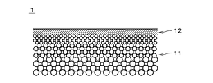
- FIG. 1 is a cross-sectional view of the zeolite membrane composite 1.
- FIG. 2 is an enlarged cross-sectional view showing a part of the zeolite membrane composite 1.
- the zeolite membrane composite 1 includes a porous support 11 and a zeolite membrane 12 formed on the support 11.
- the zeolite film 12 does not include, at least, a film in which zeolite is formed on the surface of the support 11 and in which zeolite particles are simply dispersed in an organic film.
- the zeolite membrane 12 may contain two or more types of zeolite having different structures and compositions.
- the zeolite membrane 12 is drawn with a thick line.
- the zeolite membrane 12 is shaded in parallel.
- the thickness of the zeolite membrane 12 is drawn thicker than it actually is.
- the support 11 is a porous member that can permeate gas and liquid.
- the support 11 is a monolith type in which a plurality of through holes 111 extending in the longitudinal direction (that is, the left-right direction in FIG. 1) are provided on an integrally molded columnar main body. It is a support.
- the support 11 is substantially columnar.
- the cross section perpendicular to the longitudinal direction of each through hole 111 ie, cell
- the diameter of the through hole 111 is larger than the actual diameter, and the number of the through hole 111 is smaller than the actual number.
- the zeolite membrane 12 is formed on the inner side surface of the through hole 111, and covers the inner side surface of the through hole 111 over substantially the entire surface.
- the length of the support 11 (that is, the length in the left-right direction in FIG. 1) is, for example, 10 cm to 200 cm.
- the outer diameter of the support 11 is, for example, 0.5 cm to 30 cm.
- the distance between the central axes of the adjacent through holes 111 is, for example, 0.3 mm to 10 mm.
- the surface roughness (Ra) of the support 11 is, for example, 0.1 ⁇ m to 5.0 ⁇ m, preferably 0.2 ⁇ m to 2.0 ⁇ m.
- the shape of the support 11 may be, for example, a honeycomb shape, a flat plate shape, a tubular shape, a cylindrical shape, a columnar shape, a polygonal columnar shape, or the like. When the shape of the support 11 is tubular or cylindrical, the thickness of the support 11 is, for example, 0.1 mm to 10 mm.
- the support 11 is formed of a ceramic sintered body.
- the ceramic sintered body selected as the material of the support 11 include alumina, silica, mullite, zirconia, titania, yttria, silicon nitride, silicon carbide and the like.
- the support 11 contains at least one of alumina, silica and mullite.
- the support 11 may contain an inorganic binder.
- the inorganic binder at least one of titania, mullite, easily sinterable alumina, silica, glass frit, clay mineral, and easily sinterable cordierite can be used.
- the average pore diameter of the support 11 is, for example, 0.01 ⁇ m to 70 ⁇ m, preferably 0.05 ⁇ m to 25 ⁇ m.
- the average pore diameter of the support 11 in the vicinity of the surface on which the zeolite membrane 12 is formed is 0.01 ⁇ m to 1 ⁇ m, preferably 0.05 ⁇ m to 0.5 ⁇ m.
- the average pore size can be measured, for example, with a mercury porosimeter, palm porosimeter or nanopalm porosimeter.
- D5 is, for example, 0.01 ⁇ m to 50 ⁇ m
- D50 is, for example, 0.05 ⁇ m to 70 ⁇ m
- D95 is, for example, 0.1 ⁇ m to 2000 ⁇ m. ..
- the porosity of the support 11 in the vicinity of the surface on which the zeolite membrane 12 is formed is, for example, 20% to 60%.
- the support 11 has, for example, a multilayer structure in which a plurality of layers having different average pore diameters are laminated in the thickness direction.
- the average pore diameter and sintered particle size in the surface layer including the surface on which the zeolite membrane 12 is formed are smaller than the average pore diameter and sintered particle size in the layers other than the surface layer.
- the average pore diameter of the surface layer of the support 11 is, for example, 0.01 ⁇ m to 1 ⁇ m, preferably 0.05 ⁇ m to 0.5 ⁇ m.
- the above materials can be used as the material for each layer.
- the materials of the plurality of layers forming the multilayer structure may be the same or different.
- the zeolite membrane 12 is a porous membrane having micropores (micropores).
- the zeolite membrane 12 can be used as a separation membrane that separates a specific substance from a mixed substance in which a plurality of types of substances are mixed by utilizing a molecular sieving action.
- other substances are less likely to permeate than the specific substance.
- the permeation amount of the other substance in the zeolite membrane 12 is smaller than the permeation amount of the specific substance.
- the thickness of the zeolite membrane 12 is, for example, 0.05 ⁇ m to 30 ⁇ m, preferably 0.1 ⁇ m to 20 ⁇ m, and more preferably 0.5 ⁇ m to 10 ⁇ m. Thickening the zeolite membrane 12 improves the separation performance. When the zeolite membrane 12 is thinned, the permeation rate increases.
- the surface roughness (Ra) of the zeolite membrane 12 is, for example, 5 ⁇ m or less, preferably 2 ⁇ m or less, more preferably 1 ⁇ m or less, and further preferably 0.5 ⁇ m or less.
- the pore diameter of the zeolite crystals contained in the zeolite membrane 12 (hereinafter, also simply referred to as “pore diameter of the zeolite membrane 12”) is, for example, 0.2 nm or more and 0.4 nm or less, preferably 0.25 nm or more. And it is 0.35 nm or less. If the pore diameter of the zeolite membrane 12 is less than 0.2 nm, the amount of the substance that permeates the zeolite membrane may be small, and if the pore diameter of the zeolite membrane 12 is larger than 0.4 nm, the substance selected by the zeolite membrane Insufficient sex may occur.
- the pore diameter of the zeolite membrane 12 is the diameter of the pores in a direction substantially perpendicular to the maximum diameter of the pores of the zeolite crystals constituting the zeolite membrane 12 (that is, the major axis that is the maximum value of the oxygen atom distance) (that is, that is). Short diameter).
- the pore diameter of the zeolite membrane 12 is smaller than the average pore diameter on the surface of the support 11 on which the zeolite membrane 12 is arranged.
- the minor axis of the n-membered ring pores is defined as the pore diameter of the zeolite membrane 12.
- the minor axis of the n-membered ring pore having the largest minor axis is defined as the pore diameter of the zeolite membrane 12.
- the n-membered ring is a portion in which the number of oxygen atoms constituting the skeleton forming the pores is n, and each oxygen atom is bonded to a T atom described later to form a cyclic structure.
- the n-membered ring refers to a ring having a through hole (channel), and does not include a ring having no through hole.
- the n-membered ring pores are pores formed by the n-membered ring.
- the maximum number of membered rings of zeolite contained in the above-mentioned zeolite membrane 12 is preferably 8 or less (for example, 6 or 8).
- Accessible Volume of the zeolite constituting the zeolite membrane 12 is, for example, 450 ⁇ 3 or more, preferably not 500 ⁇ 3 or more, and more preferably 550 ⁇ 3 or more. When the Accessible Volume of the zeolite membrane 12 is less than 450 ⁇ 3 , the amount of substances that permeate the zeolite membrane may decrease.
- the Accessible Volume of the zeolite membrane 12 is the volume of the volume of the space in which the water molecules can access in the zeolite crystal constituting the zeolite membrane 12 that is continuous with all the unit lattices.
- the Accessible Volume and pore size of the zeolite membrane are uniquely determined by the skeletal structure of the zeolite, and are defined by the International Zeolite Society "Database of Zeolite Structures" [online], Internet ⁇ URL: http: // www. iza-structure. It can be obtained from the values disclosed in org / database />.
- the type of zeolite constituting the zeolite membrane 12 is not particularly limited, but for example, AEI type, AEN type, AFN type, AFV type, AFX type, BEA type, CHA type, DDR type, ERI type, ETL type, FAU type ( X-type, Y-type), GIS-type, IHW-type, LEV-type, LTA-type, LTJ-type, MEL-type, MFI-type, MOR-type, PAU-type, RHO-type, SOD-type, SAT-type, etc. ..
- the zeolite is an 8-membered zeolite (that is, a zeolite having an oxygen maximum number of 8-membered rings), for example, AEI type, AFN type, AFV type, AFX type, CHA type, DDR type, ERI type, ETL.
- Zeolites of type, GIS type, IHW type, LEV type, LTA type, LTJ type, RHO type, SAT type and the like may be used.
- the type of zeolite constituting the zeolite membrane 12 is preferably AEI type, AFX type, AFV type, GIS type or SAT type zeolite, and more preferably AEI type, AFX type or SAT type zeolite.
- the zeolite constituting the zeolite film 12 contains aluminum (Al), phosphorus (P) and a tetravalent element as T atoms (that is, atoms located at the center of the oxygen tetrahedron (TO 4 ) constituting the zeolite). ..
- the tetravalent element is preferably one or more of silicon (Si), germanium (Ge), titanium (Ti) and zirconium (Zr), and more preferably one or more of Si and Ti. It is an element of, and Si is particularly preferable.
- the zeolite constituting the zeolite membrane 12 is a SAPO-type zeolite whose T atom is composed of Si, Al and P, and the T atom is composed of magnesium (Mg), Si, Al and P.
- Zn zinc
- Si Si
- Al aluminum
- P A part of the T atom may be replaced with another element.
- the zeolite constituting the zeolite membrane 12 may contain an alkali metal.
- the alkali metal is, for example, sodium (Na) or potassium (K).
- the composition of the zeolite membrane 12 is evaluated by dividing the peak area intensity of each element when the surface of the zeolite membrane 12 is measured by X-ray Photoelectron Spectroscopy (XPS) by the relative sensitivity coefficient. Can be done.
- the composition of the zeolite membrane 12 was measured by XPS after etching the membrane surface with argon by about 1 nm in order to eliminate the influence of surface contamination.
- XPS measurement conditions are: X-ray source: monochromatic Al K ⁇ ray (300 W, combined with neutralizing gun), analyzer aperture diameter: ⁇ 800 ⁇ m, charge correction: C1s, 284.8 eV, path energy: 58.7 eV, integration time: Each element was set to 4 minutes.
- the molar ratio of the tetravalent element to Al in the above-mentioned zeolite membrane 12 is 0.01 or more and 0.5 or less.
- the molar ratio of P to Al in the zeolite membrane 12 is 0.5 or more and less than 1.0. Further, the total molar ratio of the tetravalent element and P to Al in the zeolite membrane 12 is 0.9 or more and 1.3 or less.
- the composition of the zeolite membrane 12 satisfies 0.01 ⁇ X / Al ⁇ 0.5, 0.5 ⁇ P / Al ⁇ 1.0, and 0.9. Satisfy ⁇ (X + P) /Al ⁇ 1.3.
- the composition of the zeolite membrane 12 satisfies 0.01 ⁇ X / Al ⁇ 0.3 and 0.7 ⁇ P / Al ⁇ 1.0.
- the permeation flow rate (permence, unit: nmol / m 2 ⁇ s ⁇ Pa) of the single component CF 4 measured with the supply side as 0.5 MPa and the permeation side as 0.1 MPa is preferably supplied.
- the ratio of the permeation flow rate of helium to the permeation flow rate of CF 4 is 500 or more.
- the tetravalent element contained in the zeolite membrane 12 will be described as being Si.
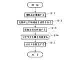
- a seed crystal used for forming the zeolite membrane 12 is generated and prepared (step S11).
- a raw material solution is prepared by dissolving or dispersing a Si source, a P source, an Al source, a structure defining agent (hereinafter, also referred to as “SDA”) or the like in a solvent. ..
- the solvent of the raw material solution for example, water or alcohol such as ethanol can be used.
- the Si source for example, colloidal silica, fumed silica, silicon alkoxide, sodium silicate and the like can be used.
- the P source for example, phosphoric acid, diphosphorus pentoxide, sodium dihydrogen phosphate, ammonium dihydrogen phosphate, phosphoric acid ester and the like can be used.
- the Al source for example, sodium aluminate, aluminum hydroxide, aluminum alkoxide, alumina sol and the like can be used.
- SDA for example, amines, quaternary ammonium salts and the like can be used.
- hydrothermal synthesis of the raw material solution is performed.
- the temperature during hydrothermal synthesis is, for example, 110 to 200 ° C.
- the hydrothermal synthesis time is, for example, 5 to 100 hours.
- the obtained crystals are washed with pure water.
- zeolite powder is produced.
- Zeolites are, for example, AEI-type zeolite, AFX-type zeolite, or SAT-type zeolite.
- the composition of zeolite can be adjusted by adjusting the mixing ratio of the raw materials (Si source, P source, Al source, etc.) in the raw material solution.
- the zeolite powder can be used as it is as a seed crystal, but a seed crystal whose particle size is adjusted according to the pore diameter of the surface layer of the support 11 by processing the powder by pulverization or the like (for example). , It is preferable to obtain a seed crystal having an average particle size larger than the average pore size of the surface layer of the support 11. Zeolite powder may be prepared by other methods.
- the porous support 11 is immersed in the dispersion liquid in which the seed crystal is dispersed, and the seed crystal is attached to the support 11 (step S12).
- the seed crystal is attached to the support 11 by bringing the dispersion liquid in which the seed crystal is dispersed into contact with the portion of the support 11 on which the zeolite membrane 12 is to be formed.
- a seed crystal adhesion support is produced.
- the seed crystal may be attached to the support 11 by another method.
- a raw material solution for immersing the support 11 to which the seed crystal is attached is prepared (step S13).
- the raw material solution is prepared by dissolving or dispersing a Si source, a P source, an Al source, an SDA, or the like in a solvent in the same manner as the raw material solution in step S11 (at the time of forming a seed crystal).
- Specific examples of the Si source, P source, Al source, SDA and solvent are the same as those of the raw material solution in step S11.
- step S13 for example, a Si source, a P source, an Al source, an SDA, or the like is added to a solvent having a pH of 5 or more and 11 or less to prepare a raw material precursor solution (step S131). Then, the raw material precursor liquid is stirred under the conditions of 10 ° C. or higher and 50 ° C. or lower for 3 hours or longer. As a result, the particle size of the sol in the raw material precursor solution becomes small, and the raw material solution having a particle size of the contained sol of 500 nm or less is produced (step S132).
- the particle size of the sol is the median diameter (D50) in the particle size distribution obtained by the laser scattering method.
- the raw material precursor solution does not necessarily have to be stirred for 3 hours or more, and may be allowed to stand for 3 hours or more, for example.
- the raw material precursor liquid may be held at 10 ° C. or higher and 50 ° C. or lower for 3 hours or longer.
- step S13 the support 11 to which the seed crystal is attached is immersed in the raw material solution. Then, the zeolite membrane 12 is formed on the support 11 by growing the zeolite around the seed crystal on the support 11 by hydrothermal synthesis (step S14).
- the temperature during hydrothermal synthesis is, for example, 110 to 200 ° C.
- the hydrothermal synthesis time is, for example, 5 to 100 hours.
- step S14 appropriate synthesis conditions are selected according to the type of zeolite to be formed, and zeolite crystal grains grow in the film thickness direction with the seed crystal as a nucleus. As a result, a zeolite membrane 12 in which a large number of zeolite crystal grains are densely spread is formed.
- the type of the raw material contained in the raw material solution in step S13 may be different from the type of the raw material contained in the raw material solution in step S11.
- the support 11 and the zeolite membrane 12 are washed with pure water. After washing, the support 11 and the zeolite membrane 12 are dried at, for example, 100 ° C. After the support 11 and the zeolite membrane 12 are dried, the zeolite membrane 12 is heat-treated in an oxidizing gas atmosphere so that the SDA in the zeolite membrane 12 is burned almost completely and desorbed from the grain boundaries and the crystal surface. Is removed (step S15). As a result, the fine pores in the zeolite membrane 12 penetrate.
- the heating temperature for removing SDA is, for example, 400 to 1000 ° C, preferably 400 to 900 ° C, and more preferably 400 to 800 ° C.
- the heating time is, for example, 10 to 200 hours.
- the oxidizing gas atmosphere is an atmosphere containing oxygen, for example, in the atmosphere. By the above treatment, the zeolite membrane composite 1 is obtained.
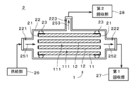
- FIG. 5 is a diagram showing the separation device 2.
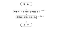
- FIG. 6 is a diagram showing a flow of separation of mixed substances by the separation device 2.
- a mixed substance containing a plurality of types of fluids that is, gas or liquid
- a highly permeable substance in the mixed substance is permeated through the zeolite membrane composite 1.
- Separation in the separation device 2 may be performed for the purpose of extracting a highly permeable substance (hereinafter, also referred to as “highly permeable substance”) from the mixed substance, and the substance having low permeability (hereinafter, “highly permeable substance”) may be extracted. It may be carried out for the purpose of concentrating (also referred to as "low permeability substance”).
- the mixed substance (that is, a mixed fluid) may be a mixed gas containing a plurality of types of gases, a mixed solution containing a plurality of types of liquids, and a gas-liquid two-phase containing both a gas and a liquid. It may be a fluid.
- the mixed substances include, for example, hydrogen (H 2 ), helium (He), nitrogen (N 2 ), oxygen (O 2 ), water (H 2 O), water vapor (H 2 O), carbon monoxide (CO), and the like.
- Carbon dioxide (CO 2 ) nitrogen oxide, ammonia (NH 3 ), sulfur oxide, hydrogen sulfide (H 2 S), sulfur fluoride, mercury (Hg), arsine (AsH 3 ), hydrogen cyanide (HCN), sulfide
- the above-mentioned highly permeable substance is, for example, one or more kinds of substances among CO 2 , NH 3 and H 2 O, and is preferably H 2 O.
- Nitrogen oxides are compounds of nitrogen and oxygen.
- the above-mentioned nitrogen oxides include, for example, nitric oxide (NO), nitrogen dioxide (NO 2 ), nitrous oxide (also referred to as dinitrogen monoxide) (N 2 O), and dinitrogen trioxide (N 2 O 3). ), Dinitrogen pentoxide (N 2 O 4 ), dinitrogen pentoxide (N 2 O 5 ) and other gases called NO X.
- Sulfur oxides are compounds of sulfur and oxygen.
- the above-mentioned sulfur oxide is, for example, a gas called SO X (socks) such as sulfur dioxide (SO 2 ) and sulfur trioxide (SO 3 ).
- Sulfur fluoride is a compound of fluorine and sulfur.
- FSSF, S SF 2
- SF 2 sulfur difluoride
- SF 4 sulfur tetrafluoride
- sulfur hexafluoride sulfur hexafluoride.
- the hydrocarbons of C1 to C8 are hydrocarbons having 1 or more carbon atoms and 8 or less carbon atoms.
- the hydrocarbons of C3 to C8 may be any of a linear compound, a side chain compound and a cyclic compound.
- the hydrocarbons C2 to C8 are saturated hydrocarbons (that is, those in which double bonds and triple bonds are not present in the molecule) and unsaturated hydrocarbons (that is, double bonds and / or triple bonds are molecules. It may be either of those present in it).
- the above-mentioned organic acid is a carboxylic acid, a sulfonic acid or the like.
- Carboxylic acids include, for example, formic acid (CH 2 O 2 ), acetic acid (C 2 H 4 O 2 ), oxalic acid (C 2 H 2 O 4 ), acrylic acid (C 3 H 4 O 2 ) or benzoic acid (C 3 H 4 O 2 ). 6 H 5 COOH) and the like.
- the sulfonic acid is, for example, ethane sulfonic acid (C 2 H 6 O 3 S) or the like.
- the organic acid may be a chain compound or a cyclic compound.
- the alcohols described above include, for example, methanol (CH 3 OH), ethanol (C 2 H 5 OH), isopropanol (2-propanol) (CH 3 CH (OH) CH 3 ), ethylene glycol (CH 2 (OH) CH 2 ). (OH)) or butanol (C 4 H 9 OH) and the like.
- Mercaptans are organic compounds having hydrogenated sulfur (SH) at the end, and are substances also called thiols or thioalcohols.
- the above-mentioned mercaptans are, for example, methyl mercaptan (CH 3 SH), ethyl mercaptan (C 2 H 5 SH), 1-propanethiol (C 3 H 7 SH) and the like.
- ester is, for example, formate ester or acetic acid ester.
- ethers include, for example, dimethyl ether ((CH 3 ) 2 O), methyl ethyl ether (C 2 H 5 OCH 3 ) or diethyl ether ((C 2 H 5 ) 2 O).
- ketone is, for example, acetone ((CH 3 ) 2 CO), methyl ethyl ketone (C 2 H 5 COCH 3 ) or diethyl ketone ((C 2 H 5 ) 2 CO).
- aldehydes are, for example, acetaldehyde (CH 3 CHO), propionaldehyde (C 2 H 5 CHO) or butanal (butyraldehyde) (C 3 H 7 CHO).
- the mixed substance separated by the separation device 2 will be described as a mixed liquid containing a plurality of types of liquids.
- the separation device 2 includes a zeolite membrane composite 1, a sealing section 21, an outer cylinder 22, two sealing members 23, a supply section 26, a first recovery section 27, and a second recovery section 28. ..
- the zeolite membrane composite 1, the sealing portion 21, and the sealing member 23 are housed in the outer cylinder 22.
- the supply unit 26, the first collection unit 27, and the second collection unit 28 are arranged outside the outer cylinder 22 and connected to the outer cylinder 22.
- the sealing portions 21 are attached to both ends of the support 11 in the longitudinal direction (that is, the left-right direction in FIG. 5), and cover both end faces in the longitudinal direction of the support 11 and outer surfaces in the vicinity of both end faces. It is a member to be sealed.
- the sealing portion 21 prevents the inflow and outflow of the liquid from the both end faces of the support 11.
- the sealing portion 21 is, for example, a plate-shaped member formed of glass or resin. The material and shape of the sealing portion 21 may be changed as appropriate. Since the sealing portion 21 is provided with a plurality of openings overlapping the plurality of through holes 111 of the support 11, both ends of each through hole 111 of the support 11 in the longitudinal direction are covered with the sealing portion 21. It has not been. Therefore, the inflow and outflow of the liquid or the like from both ends into the through hole 111 is possible.
- the shape of the outer cylinder 22 is not particularly limited, but is, for example, a substantially cylindrical tubular member.
- the outer cylinder 22 is made of, for example, stainless steel or carbon steel.
- the longitudinal direction of the outer cylinder 22 is substantially parallel to the longitudinal direction of the zeolite membrane composite 1.
- a supply port 221 is provided at one end of the outer cylinder 22 in the longitudinal direction (that is, the left end in FIG. 5), and a first discharge port 222 is provided at the other end.
- a second discharge port 223 is provided on the side surface of the outer cylinder 22.
- a supply unit 26 is connected to the supply port 221.
- the first collection unit 27 is connected to the first discharge port 222.
- the second collection unit 28 is connected to the second discharge port 223.
- the internal space of the outer cylinder 22 is a closed space isolated from the space around the outer cylinder 22.
- the two sealing members 23 are arranged over the entire circumference between the outer surface of the zeolite membrane composite 1 and the inner surface of the outer cylinder 22 in the vicinity of both ends in the longitudinal direction of the zeolite membrane composite 1.
- Each sealing member 23 is a substantially annular member formed of a material that does not allow liquid to permeate.
- the seal member 23 is, for example, an O-ring made of a flexible resin.
- the sealing member 23 is in close contact with the outer surface of the zeolite membrane composite 1 and the inner surface of the outer cylinder 22 over the entire circumference. In the example shown in FIG. 5, the sealing member 23 is in close contact with the outer surface of the sealing portion 21, and indirectly adheres to the outer surface of the zeolite membrane composite 1 via the sealing portion 21.
- the space between the sealing member 23 and the outer surface of the zeolite membrane composite 1 and the space between the sealing member 23 and the inner surface of the outer cylinder 22 are sealed, and the passage of liquid is almost or completely impossible. ..
- the supply unit 26 supplies the mixed liquid to the internal space of the outer cylinder 22 via the supply port 221.
- the supply unit 26 includes, for example, a pump that pumps the mixed liquid toward the outer cylinder 22.
- the pump includes a temperature control unit and a pressure control unit that adjust the temperature and pressure of the mixed liquid supplied to the outer cylinder 22, respectively.
- the first collection unit 27 includes, for example, a storage container for storing the liquid led out from the outer cylinder 22, or a pump for transferring the liquid.
- the second recovery unit 28 includes, for example, a vacuum pump that depressurizes the space outside the outer surface of the zeolite membrane composite 1 in the outer cylinder 22 (that is, the space sandwiched between the two sealing members 23), and the zeolite membrane. It is provided with a liquid nitrogen trap that vaporizes the complex 1 and cools and liquefies the permeated gas.
- the zeolite membrane composite 1 is prepared by preparing the above-mentioned separation device 2 (FIG. 6: step S21). Subsequently, the supply unit 26 supplies a mixed liquid containing a plurality of types of liquids having different permeability to the zeolite membrane 12 to the internal space of the outer cylinder 22.
- the main components of the mixed solution are water (H 2 O) and ethanol (C 2 H 5 OH).
- the mixed solution may contain a liquid other than water and ethanol.
- the pressure (that is, the introduction pressure) of the mixed solution supplied from the supply unit 26 to the internal space of the outer cylinder 22 is, for example, 0.1 MPa to 2 MPa, and the temperature of the mixed solution is, for example, 10 ° C. to 200 ° C. Is.
- the mixed solution supplied from the supply unit 26 to the outer cylinder 22 is introduced into each through hole 111 of the support 11 from the left end in the drawing of the zeolite membrane composite 1 as shown by an arrow 251.
- the highly permeable substance which is a highly permeable liquid in the mixed liquid, permeates through the zeolite membrane 12 provided on the inner side surface of each through hole 111 and the support 11 while evaporating to the outside of the support 11. Derived from the side.
- the highly permeable substance for example, water
- the low permeable substance for example, ethanol
- the gas derived from the outer surface of the support 11 (hereinafter referred to as “permeated substance”) is guided to the second recovery unit 28 via the second discharge port 223 as shown by the arrow 253. It is cooled in the second recovery unit 28 and recovered as a liquid.
- the pressure (that is, permeation pressure) of the gas recovered by the second recovery unit 28 via the second discharge port 223 is, for example, about 50 Torr (about 6.67 kPa).
- the permeable substance may include a low permeable substance that has permeated the zeolite membrane 12 in addition to the above-mentioned highly permeable substance.
- the liquid excluding the substance that has permeated the zeolite membrane 12 and the support 11 (hereinafter, referred to as “impermeable substance”) has the through holes 111 of the support 11 from the left side to the right side in the drawing. As shown by the arrow 252, it is collected by the first collection unit 27 via the first discharge port 222.
- the pressure of the liquid recovered by the first recovery unit 27 via the first discharge port 222 is, for example, substantially the same as the introduction pressure.
- the impermeable substance may include a highly permeable substance that has not permeated the zeolite membrane 12.
- the impermeable substance recovered by the first recovery unit 27 may be circulated to the supply unit 26 and supplied again into the outer cylinder 22, for example.
- the separation device 2 shown in FIG. 5 may be used as, for example, a membrane type reaction device.
- the outer cylinder 22 is used as a reactor.
- a catalyst that promotes a chemical reaction of the raw material material supplied from the supply unit 26 is housed inside the outer cylinder 22 .
- the catalyst is arranged, for example, between the supply port 221 and the first discharge port 222.
- the catalyst is arranged in the vicinity of the zeolite membrane 12 of the zeolite membrane composite 1.
- a catalyst having an appropriate material and shape is used depending on the type of the raw material and the type of the chemical reaction caused in the raw material.
- the raw material contains one kind or two or more kinds of substances.
- the membrane-type reactor may further include a reactor (that is, an outer cylinder 22) and a heating device for heating the raw material in order to promote a chemical reaction of the raw material.
- a mixed substance containing a product substance produced by a chemical reaction of the raw material substance in the presence of a catalyst is supplied to the zeolite membrane 12 in the same manner as described above, and the mixed substance is supplied.
- the mixed substance may be a fluid containing the product and an unreacted raw material.
- the mixed substance may contain two or more kinds of product substances.
- the highly permeable substance may be a product substance produced from the raw material, or may be a substance other than the product substance.
- the highly permeable material comprises one or more producting materials.
- the highly permeable substance is a product substance produced from a raw material
- the yield of the product substance can be improved by separating the product substance from other substances by the zeolite membrane 12.
- the two or more kinds of product substances may be highly permeable substances, and among the two or more kinds of product substances, some kinds of product substances May be a highly permeable substance.
- the separation performance is such that a mixed solution of water and ethanol is supplied from the supply unit 26 to the zeolite membrane composite 1 in the outer cylinder 22 and permeates through the zeolite membrane composite 1 to the second recovery unit. It was determined from the permeate (that is, the permeate) recovered in No. 28. Specifically, the separation performance is such that the water concentration (mass%) in the permeated substance recovered by the second recovery unit 28 and the ethanol concentration (mass%) in the permeated substance recovered by the second recovery unit 28. It is the value divided by (that is, the separation ratio of water and ethanol).
- the temperature of the mixed solution supplied from the supply unit 26 was 60 ° C., and the proportions of water and ethanol in the mixed solution were 50% by mass, respectively.
- Example 1 the zeolite membrane composite 1 was prepared as follows. First, the SAT-type zeolite powder obtained by hydrothermal synthesis is used as a seed crystal, and the support 11 is brought into contact with a solution in which the seed crystal is poured into pure water so as to have a predetermined mixing ratio. Seed crystals were attached to the inside.
- the support 11 to which the seed crystals were attached was immersed in the raw material solution and hydrothermally synthesized at 170 ° C. for 50 hours to form a SAT-type zeolite membrane 12 on the support 11. Then, the support 11 on which the zeolite membrane 12 was formed was thoroughly washed with pure water and completely dried at 90 ° C. Next, the support 11 on which the zeolite membrane 12 was formed was heated in the air at 500 ° C. for 20 hours to burn off the SDA and penetrate the pores in the zeolite membrane 12.
- the permeation flow velocity of the single component CF 4 was measured with the supply side set to 0.5 MPa and the permeation side set to 0.1 MPa, and the supply side set to 0.2 MPa and the permeation side set to 0.1 MPa.
- the permeation flow rate of the single component helium was measured.
- the ratio of the permeation flow rate of helium to the permeation flow rate of the obtained CF 4 was 500 or more.
- the production of the zeolite membrane composite 1 in Example 2 was different from that in Example 1 except that the composition of the raw material solution was 0.3SiO 2 : 1Al 2 O 3 : 2P 2 O 5 : 2.3 SDA: 1000H 2 O. It is almost the same.
- Si / Al was 0.28
- P / Al was 0.74
- (Si + P) / Al was 1.03. there were.
- the separation ratio of water and ethanol in Example 2 was 968, showing high separation performance.
- the ratio of the permeation flow rate of helium to the permeation flow rate of CF 4 in Example 2 was 500 or more.
- the measurement conditions of the permeation flow velocity of CF 4 and helium in Example 2, Examples 3 to 5 described later, and Comparative Examples 1 and 2 are the same as those in Example 1.
- Example 4 In the production of the zeolite membrane composite 1 in Example 4, titanium isopropoxide was used as the Ti source, and the composition of the raw material solution was 0.1 TiO 2 : 1Al 2 O 3 : 2P 2 O 5 : 2.3 SDA: 1000H 2 O. It is substantially the same as that of Example 1 except that As a result of measuring the surface composition of the zeolite membrane 12 in Example 4 by the above-mentioned XPS, Ti / Al was 0.08, P / Al was 0.93, and (Ti + P) / Al was 1.01. there were. The separation ratio of water and ethanol in Example 4 was 926, showing high separation performance. The ratio of permeation rate of helium for the permeation rate of CF 4 in Example 4 was 500 or more.
- Example 5 the zeolite membrane composite 1 was prepared as follows. First, the AFX-type zeolite powder obtained by hydrothermal synthesis is used as a seed crystal, and the support 11 is brought into contact with a solution in which the seed crystal is poured into pure water so as to have a predetermined mixing ratio. Seed crystals were attached to the inside.
- the support 11 to which the seed crystals were attached was immersed in the raw material solution and hydrothermally synthesized at 170 ° C. for 50 hours to form an AFX-type zeolite membrane 12 on the support 11. Then, the support 11 on which the zeolite membrane 12 was formed was thoroughly washed with pure water and completely dried at 90 ° C. Next, the support 11 on which the zeolite membrane 12 was formed was heated in the air at 500 ° C. for 20 hours to burn off the SDA and penetrate the pores in the zeolite membrane 12.
- Example 5 As a result of measuring the surface composition of the zeolite membrane 12 in Example 5 by the above-mentioned XPS, Si / Al was 0.20, P / Al was 0.87, and (Si + P) / Al was 1.07. there were.
- the separation ratio of water and ethanol in Example 5 was 753, showing high separation performance. Further, the ratio of the permeation flow rate of helium to the permeation flow rate of CF 4 in Example 5 was 500 or more.
- Example 6 the zeolite membrane composite 1 was prepared as follows. First, the AEI-type zeolite powder obtained by hydrothermal synthesis is used as a seed crystal, and the support 11 is brought into contact with a solution in which the seed crystal is added to pure water so as to have a predetermined mixing ratio. A seed crystal was attached to the inside of 111.
- the support 11 to which the seed crystals were attached was immersed in the raw material solution and hydrothermally synthesized at 180 ° C. for 30 hours to form an AEI-type zeolite membrane 12 on the support 11. Then, the support 11 on which the zeolite membrane 12 was formed was thoroughly washed with pure water and completely dried at 90 ° C. Next, the support 11 on which the zeolite membrane 12 was formed was heated in the air at 500 ° C. for 20 hours to burn off the SDA and penetrate the pores in the zeolite membrane 12.
- the production of the zeolite membrane composite 1 in Comparative Example 1 is substantially the same as that in Example 1 except that the stirring time of the raw material precursor solution is reduced to 15 minutes.
- the particle size of the sol in the raw material precursor solution of Comparative Example 1 was larger than 500 nm.
- Si / Al was 0.10
- P / Al was 1.04
- (Si + P) / Al was 1.14. there were.
- the separation ratio of water and ethanol in Comparative Example 1 was 20 or less, and the separation performance was low.
- the ratio of the permeation flow rate of helium to the permeation flow rate of CF 4 in Comparative Example 1 was less than 100.
- the production of the zeolite membrane composite 1 in Comparative Example 2 is substantially the same as that in Example 2 except that the stirring time of the raw material precursor liquid is reduced to 15 minutes.
- the particle size of the sol in the raw material precursor solution of Comparative Example 2 was larger than 500 nm.
- Si / Al was 0.64
- P / Al was 1.01
- (Si + P) / Al was 1.65. there were.
- the separation ratio of water and ethanol in Comparative Example 2 was 10 or less, and the separation performance was low. Further, the ratio of the permeation flow rate of helium to the permeation flow rate of CF 4 in Comparative Example 2 was less than 100.
- the composition of the zeolite membrane 12 measured by X-ray photoelectron spectroscopy is that of Si with respect to Al.
- the molar ratio is 0.01 or more and 0.5 or less
- the molar ratio of P to Al is 0.5 or more and less than 1.0
- the total molar ratio of Si and P to Al is 0.9.
- the zeolite membrane composite 1 includes a porous support 11 and a zeolite membrane 12 formed on the support 11.
- the zeolite membrane 12 contains Al, P, and a tetravalent element.
- the molar ratio of the tetravalent element to Al is 0.01 or more and 0.5 or less
- the molar ratio of P to Al is 0.5 or more.
- the total molar ratio of the tetravalent element and P to Al is 0.9 or more and 1.3 or less.
- the pentavalent P site is preferentially replaced by the tetravalent element as compared with the trivalent Al site. ..
- pentavalent P sites are selectively substituted with tetravalent elements. Therefore, the affinity of the zeolite membrane 12 for polar molecules can be improved. As a result, the permeability of polar molecules in the zeolite membrane 12 can be improved.
- the molar ratio of the tetravalent element to Al is 0.01 or more and 0.3 or less, and the molar ratio of P to Al is , 0.7 or more and less than 1.0.
- the water resistance of the zeolite membrane can be increased.
- the composition of the above-mentioned zeolite membrane 12 is measured by energy dispersive X-ray analysis (EDX or EDS: Energy Dispersive X-ray Spectrometry)
- EDX or EDS Energy Dispersive X-ray Spectrometry
- the molar ratio of the above tetravalent element to Al is 0.01 or more and 0. It became .45 or less.
- the molar ratio of P to Al was 0.45 or more and less than 1.0.
- the total molar ratio of the tetravalent element and P to Al was 0.8 or more and 1.2 or less.
- the measurement conditions by EDX (EDS) are an accelerating voltage: 10 kV, a detector: a silicon drift detector, and a field magnification: 5000 times.
- EDX is a composition evaluation method that includes not only the surface of the membrane but also the inside of the membrane, and the evaluation result may change depending on the production conditions of the zeolite membrane 12.
- composition information of only the membrane surface that most affects the separation performance of the zeolite membrane 12 can be evaluated. Therefore, it is difficult to obtain a direct correlation between the measurement result by X-ray photoelectron spectroscopy and the measurement result by EDX (EDS), so caution is required.
- the pore diameter of the zeolite crystals contained in the zeolite membrane 12 is preferably 0.4 nm or less.
- the zeolite membrane 12 is composed of AEI type, AFX type or SAT type zeolite.
- zeolite membrane By constructing the zeolite membrane from zeolite crystals having a relatively small pore diameter in this way, selective permeation of a permeation target substance having a small molecular diameter can be suitably realized, and the permeation target substance can be efficiently made from a mixed substance. Can be separated well.
- the tetravalent element is preferably one or more of Si and Ti, and more preferably Si.
- the permeability of polar molecules in the zeolite membrane 12 can be further improved.
- the permeation flow rate of the single component CF 4 measured with the supply side as 0.5 MPa and the permeation side as 0.1 MPa, the supply side as 0.2 MPa, and the permeation side as 0.1 MPa.
- the ratio of the permeation flow rate of helium to the permeation flow rate of CF 4 is preferably 500 or more with respect to the permeation flow rate of the single component helium measured as.
- the support 11 is preferably an alumina sintered body, a mullite sintered body, or a titania sintered body. As a result, the adhesion between the zeolite membrane 12 and the support 11 can be improved.
- the above-mentioned method for producing the zeolite membrane composite 1 includes a step of adding at least an Al source, a P source and an SDA to a solvent to prepare a raw material precursor solution (step S131), and the raw material precursor solution having a pH of 5 or more and a pH of 11 or less.
- a step of immersing the support and forming a zeolite film 12 on the support 11 by hydrothermal synthesis is provided.
- the zeolite membrane 12 contains Al, P, and a tetravalent element.
- the molar ratio of the tetravalent element to Al is 0.01 or more and 0.5 or less
- the molar ratio of P to Al is 0.5 or more
- the total molar ratio of the tetravalent element and P to Al is 0.9 or more and 1.3 or less.
- the separation device 2 includes the zeolite membrane composite 1 and a supply unit 26 that supplies a mixed substance containing a plurality of types of gases or liquids to the zeolite membrane composite 1.
- the zeolite membrane composite 1 is separated from other substances by permeating a highly permeable substance in the mixed substance.
- the highly permeable substance which is a polar molecule, can be efficiently separated from other substances. Therefore, the separator 2 is suitable for separating one or more substances among CO 2 , NH 3 and H 2 O, and is particularly suitable for separating H 2 O.
- the membrane-type reactor includes the zeolite membrane composite 1, a catalyst that promotes a chemical reaction of the raw material, and a reactor that houses the zeolite membrane composite 1 and the catalyst (in the above example, the outside).
- the cylinder 22) and a supply unit 26 for supplying the raw material to the reactor are provided.
- the zeolite membrane composite 1 separates from other substances by permeating a highly permeable, highly permeable substance among the mixed substances containing the product produced by the chemical reaction of the raw material in the presence of a catalyst. ..
- the membrane-type reactor is suitable for separating one or more substances among CO 2 , NH 3 and H 2 O, and is particularly suitable for separating H 2 O.
- the step of preparing the zeolite membrane composite 1 (step S21) and a mixed substance containing a plurality of types of gases or liquids are supplied to the zeolite membrane composite 1, and the permeability in the mixed substance is increased.
- a step (step S22) of separating a highly permeable substance from another substance by permeating the zeolite membrane composite 1 is provided.
- the separation method is suitable for the separation of one or more substances among CO 2 , NH 3 and H 2 O, and is particularly suitable for the separation of H 2 O.
- the tetravalent element contained in the zeolite membrane 12 may be an element other than Si, Ge, Ti and Zr.
- the tetravalent element may be eluted from the support 11 in the formation of the zeolite membrane 12 described above (FIG. 3: step S14).
- the eluted tetravalent element may also be used as an element constituting the zeolite membrane 12.
- the raw material solution prepared in step S13 may not contain the element.
- the pore diameter (that is, minor diameter) of the zeolite crystals contained in the zeolite membrane 12 may be larger than 0.4 nm. Further, the maximum number of membered rings of the zeolite crystal contained in the zeolite membrane 12 may be larger than 8.
- the treatment of adhering the seed crystal on the support 11 (FIGS. 3: steps S11 and S12) is omitted, and the zeolite membrane 12 is directly placed on the support 11 in the treatments of steps S13 and S14. It is also possible to form.
- the zeolite membrane 12 in which the zeolite crystal grains are densely formed, it is preferable to attach the seed crystal on the support 11 before forming the zeolite membrane 12.
- the zeolite membrane composite 1 may further include a functional membrane or a protective membrane laminated on the zeolite membrane 12 in addition to the support 11 and the zeolite membrane 12.
- a functional film or a protective film may be an inorganic film such as a zeolite film, a silica film or a carbon film, or an organic film such as a polyimide film or a silicone film.
- a substance that easily adsorbs water may be added to the functional film or the protective film laminated on the zeolite membrane 12.
- the mixed substance may be separated by a vapor permeation method, a reverse osmosis method, a gas permeation method, or the like, in addition to the permeation vaporization method exemplified in the above description.
- a vapor permeation method a reverse osmosis method, a gas permeation method, or the like, in addition to the permeation vaporization method exemplified in the above description.
- the membrane type reactor the same applies to the membrane type reactor.
- the zeolite membrane composite of the present invention can be used as, for example, a dehydration membrane, and further, in various fields in which zeolite is used as a separation membrane for various substances other than water, an adsorption membrane for various substances, and the like. It is available.
Landscapes
- Chemical & Material Sciences (AREA)
- Chemical Kinetics & Catalysis (AREA)
- Engineering & Computer Science (AREA)
- Inorganic Chemistry (AREA)
- Organic Chemistry (AREA)
- Geology (AREA)
- Life Sciences & Earth Sciences (AREA)
- General Life Sciences & Earth Sciences (AREA)
- Materials Engineering (AREA)
- Ceramic Engineering (AREA)
- Crystallography & Structural Chemistry (AREA)
- Manufacturing & Machinery (AREA)
- Structural Engineering (AREA)
- Analytical Chemistry (AREA)
- General Chemical & Material Sciences (AREA)
- Oil, Petroleum & Natural Gas (AREA)
- Separation Using Semi-Permeable Membranes (AREA)
- Silicates, Zeolites, And Molecular Sieves (AREA)
- Physical Or Chemical Processes And Apparatus (AREA)
Abstract
ゼオライト膜複合体(1)は、多孔質の支持体(11)と、支持体(11)上に形成されたゼオライト膜(12)と、を備える。ゼオライト膜(12)は、Alと、Pと、4価元素とを含む。X線光電子分光法により測定したゼオライト膜(12)の組成において、Alに対する当該4価元素のモル比率は、0.01以上かつ0.5以下であり、Alに対するPのモル比率は、0.5以上かつ1.0未満であり、Alに対する上記4価元素およびPの合計モル比率は、0.9以上かつ1.3以下である。このため、ゼオライト膜(12)における極性分子の透過性を向上することができる。
Description
本発明は、ゼオライト膜複合体およびその製造方法、並びに、当該ゼオライト膜複合体を用いた混合物質の分離に関する。
[関連出願の参照]
本願は、2019年6月17日に出願された日本国特許出願JP2019-111809、および、2020年5月11日に出願された国際特許出願PCT/JP2020/018846からの優先権の利益を主張し、当該出願の全ての開示は、本願に組み込まれる。
[関連出願の参照]
本願は、2019年6月17日に出願された日本国特許出願JP2019-111809、および、2020年5月11日に出願された国際特許出願PCT/JP2020/018846からの優先権の利益を主張し、当該出願の全ての開示は、本願に組み込まれる。
現在、多孔質支持体上にゼオライト膜を形成してゼオライト膜複合体とすることにより、ゼオライトの分子篩作用を利用した特定の分子の分離や分子の吸着等の用途について、様々な研究や開発が行われている。例えば、複数種類のガスまたは液体を含む混合物質の分離では、混合物質をゼオライト膜複合体に供給し、高透過性の物質を透過させることにより他の物質から分離させる。
国際公開第2018/225793号(文献1)では、ERI型の結晶構造を有するALPO型のゼオライト膜(ALPO-17)により、水を含む混合物質から水を選択的に分離する脱水装置が開示されている。国際公開第2018/180563号(文献2)および国際公開第2018/180564号(文献3)では、AFX型の結晶構造を有するSAPO型のゼオライト膜(SAPO-56)により、CO2およびCH4を含む混合ガスを分離する技術が開示されている。Shiguang Li et al., Scale-up of SAPO-34 membranes for CO2/CH4 separation, Journal of Membrane Science, 2010, 352, 7-13(文献4)では、CHA型の結晶構造を有するSAPO型のゼオライト膜(SAPO-34)により、CO2およびCH4を含む混合ガスを分離する技術が開示されている。
ところで、ALPO型のゼオライト膜では、極性分子に対する親和性が比較的低いため、極性分子の透過性向上に限界がある。そこで、ALPO型のゼオライト膜のゼオライト骨格中にケイ素等の4価元素を導入することにより、極性分子の透過性を向上することが考えられるが、単に4価元素を導入すればよいわけではなく、4価元素の導入サイトを好適に制御する必要がある。しかしながら、4価元素を導入しつつゼオライト膜を合成する場合、ゼオライト粉末の合成時における4価元素の導入と異なり、支持体上でのゼオライト合成となるため、4価元素の導入サイトの制御は容易ではない。
本発明は、ゼオライト膜複合体に向けられており、ゼオライト膜における極性分子の透過性を向上することを目的としている。
本発明の好ましい一の形態に係るゼオライト膜複合体は、多孔質の支持体と、前記支持体上に形成されたゼオライト膜と、を備える。前記ゼオライト膜は、アルミニウムと、リンと、4価元素と、を含む。X線光電子分光法により測定した前記ゼオライト膜の組成において、前記アルミニウムに対する前記4価元素のモル比率は、0.01以上かつ0.5以下であり、前記アルミニウムに対する前記リンのモル比率は、0.5以上かつ1.0未満であり、前記アルミニウムに対する前記4価元素および前記リンの合計モル比率は、0.9以上かつ1.3以下である。当該ゼオライト膜複合体によれば、極性分子の透過性を向上することができる。
好ましくは、X線光電子分光法により測定した前記ゼオライト膜の組成において、前記アルミニウムに対する前記4価元素のモル比率は、0.01以上かつ0.3以下であり、前記アルミニウムに対する前記リンのモル比率は、0.7以上かつ1.0未満である。
好ましくは、前記ゼオライト膜に含まれるゼオライト結晶の細孔径は0.4nm以下である。
好ましくは、前記ゼオライト膜に含まれるゼオライト結晶のAccessible Volumeは、450Å3以上である。
好ましくは、前記ゼオライト膜は、AEI型、AFX型またはSAT型のゼオライトにより構成される。
好ましくは、前記4価元素は、ケイ素およびチタンのうち1種類以上の元素である。より好ましくは、前記4価元素は、ケイ素である。
好ましくは、前記ゼオライト膜では、供給側を0.5MPa(以下、すべて絶対圧)、透過側を0.1MPaとして測定した単成分CF4の透過流速と、供給側を0.2MPa、透過側を0.1MPaとして測定した単成分ヘリウムの透過流速について、CF4の透過流速に対するヘリウムの透過流速の割合は500以上である。
好ましくは、前記支持体は、アルミナ焼結体、ムライト焼結体またはチタニア焼結体である。
本発明は、ゼオライト膜複合体の製造方法にも向けられている。本発明の好ましい一の形態に係るゼオライト膜の製造方法は、a)溶媒に少なくともアルミニウム源、リン源および構造規定剤を加えて原料前駆液を作製する工程と、b)前記原料前駆液を、pH5以上かつpH11以下および10℃以上かつ50℃以下の条件下にて3時間以上保持することにより、含有されるゾルの粒径が500nm以下の原料溶液を生成する工程と、c)前記原料溶液に多孔質の支持体を浸漬し、水熱合成により前記支持体上にゼオライト膜を形成する工程と、を備える。前記ゼオライト膜は、アルミニウムと、リンと、4価元素と、を含む。X線光電子分光法により測定した前記ゼオライト膜の組成において、前記アルミニウムに対する前記4価元素のモル比率は、0.01以上かつ0.5以下であり、前記アルミニウムに対する前記リンのモル比率は、0.5以上かつ1.0未満であり、前記アルミニウムに対する前記4価元素および前記リンの合計モル比率は、0.9以上かつ1.3以下である。当該ゼオライト膜複合体の製造方法によれば、極性分子の透過性を向上することができる。
本発明は、分離装置にも向けられている。本発明の好ましい一の形態に係る分離装置は、上述のゼオライト膜複合体と、複数種類のガスまたは液体を含む混合物質を前記ゼオライト膜複合体に供給する供給部と、を備える。前記ゼオライト膜複合体は、前記混合物質中の透過性が高い高透過性物質を透過することにより他の物質から分離する。
好ましくは、前記高透過性物質は、NH3、CO2およびH2Oのうち1種類以上の物質である。
好ましくは、前記高透過性物質は、H2Oである。
本発明は、膜型反応装置にも向けられている。本発明の好ましい一の形態に係る膜型反応装置は、上述のゼオライト膜複合体と、原料物質の化学反応を促進させる触媒と、前記ゼオライト膜複合体および前記触媒を収容する反応器と、前記原料物質を前記反応器に供給する供給部と、を備える。前記ゼオライト膜複合体は、前記原料物質が前記触媒存在下で化学反応することにより生成された生成物質を含む混合物質のうち、透過性が高い高透過性物質を透過することにより他の物質から分離する。
好ましくは、前記高透過性物質は、NH3、CO2およびH2Oのうち1種類以上の物質である。
好ましくは、前記高透過性物質は、H2Oである。
本発明は、分離方法にも向けられている。本発明の好ましい一の形態に係る分離方法は、d)上述のゼオライト膜複合体を準備する工程と、e)複数種類のガスまたは液体を含む混合物質を前記ゼオライト膜複合体に供給し、前記混合物質中の透過性が高い高透過性物質を、前記ゼオライト膜複合体を透過させることにより他の物質から分離する工程と、を備える。
好ましくは、前記高透過性物質は、NH3、CO2およびH2Oのうち1種類以上の物質である。
好ましくは、前記高透過性物質は、H2Oである。
上述の目的および他の目的、特徴、態様および利点は、添付した図面を参照して以下に行うこの発明の詳細な説明により明らかにされる。
図1は、ゼオライト膜複合体1の断面図である。図2は、ゼオライト膜複合体1の一部を拡大して示す断面図である。ゼオライト膜複合体1は、多孔質の支持体11と、支持体11上に形成されゼオライト膜12とを備える。ゼオライト膜12とは、少なくとも、支持体11の表面にゼオライトが膜状に形成されたものであって、有機膜中にゼオライト粒子を分散させただけのものは含まない。また、ゼオライト膜12は、構造や組成が異なる2種類以上のゼオライトを含んでいてもよい。図1では、ゼオライト膜12を太線にて描いている。図2では、ゼオライト膜12に平行斜線を付す。また、図2では、ゼオライト膜12の厚さを実際よりも厚く描いている。
支持体11はガスおよび液体を透過可能な多孔質部材である。図1に示す例では、支持体11は、一体成形された一繋がりの柱状の本体に、長手方向(すなわち、図1中の左右方向)にそれぞれ延びる複数の貫通孔111が設けられたモノリス型支持体である。図1に示す例では、支持体11は略円柱状である。各貫通孔111(すなわち、セル)の長手方向に垂直な断面は、例えば略円形である。図1では、貫通孔111の径を実際よりも大きく、貫通孔111の数を実際よりも少なく描いている。ゼオライト膜12は、貫通孔111の内側面上に形成され、貫通孔111の内側面を略全面に亘って被覆する。
支持体11の長さ(すなわち、図1中の左右方向の長さ)は、例えば10cm~200cmである。支持体11の外径は、例えば0.5cm~30cmである。隣接する貫通孔111の中心軸間の距離は、例えば0.3mm~10mmである。支持体11の表面粗さ(Ra)は、例えば0.1μm~5.0μmであり、好ましくは0.2μm~2.0μmである。なお、支持体11の形状は、例えば、ハニカム状、平板状、管状、円筒状、円柱状または多角柱状等であってもよい。支持体11の形状が管状または円筒状である場合、支持体11の厚さは、例えば0.1mm~10mmである。
支持体11の材料は、表面にゼオライト膜12を形成する工程において化学的安定性を有するのであれば、様々な物質(例えば、セラミックまたは金属)が採用可能である。本実施の形態では、支持体11はセラミック焼結体により形成される。支持体11の材料として選択されるセラミック焼結体としては、例えば、アルミナ、シリカ、ムライト、ジルコニア、チタニア、イットリア、窒化ケイ素、炭化ケイ素等が挙げられる。本実施の形態では、支持体11は、アルミナ、シリカおよびムライトのうち、少なくとも1種類を含む。
支持体11は、無機結合材を含んでいてもよい。無機結合材としては、チタニア、ムライト、易焼結性アルミナ、シリカ、ガラスフリット、粘土鉱物、易焼結性コージェライトのうち少なくとも1つを用いることができる。
支持体11の平均細孔径は、例えば0.01μm~70μmであり、好ましくは0.05μm~25μmである。ゼオライト膜12が形成される表面近傍における支持体11の平均細孔径は0.01μm~1μmであり、好ましくは0.05μm~0.5μmである。平均細孔径は、例えば、水銀ポロシメータ、パームポロシメータまたはナノパームポロシメータにより測定することができる。支持体11の表面および内部を含めた全体における細孔径の分布について、D5は例えば0.01μm~50μmであり、D50は例えば0.05μm~70μmであり、D95は例えば0.1μm~2000μmである。ゼオライト膜12が形成される表面近傍における支持体11の気孔率は、例えば20%~60%である。
支持体11は、例えば、平均細孔径が異なる複数の層が厚さ方向に積層された多層構造を有する。ゼオライト膜12が形成される表面を含む表面層における平均細孔径および焼結粒径は、表面層以外の層における平均細孔径および焼結粒径よりも小さい。支持体11の表面層の平均細孔径は、例えば0.01μm~1μmであり、好ましくは0.05μm~0.5μmである。支持体11が多層構造を有する場合、各層の材料は上記のものを用いることができる。多層構造を形成する複数の層の材料は、同じであってもよく、異なっていてもよい。
ゼオライト膜12は、微細孔(マイクロ孔)を有する多孔膜である。ゼオライト膜12は、複数種類の物質が混合した混合物質から、分子篩作用を利用して特定の物質を分離する分離膜として利用可能である。ゼオライト膜12では、当該特定の物質に比べて他の物質が透過しにくい。換言すれば、ゼオライト膜12の当該他の物質の透過量は、上記特定の物質の透過量に比べて小さい。
ゼオライト膜12の厚さは、例えば0.05μm~30μmであり、好ましくは0.1μm~20μmであり、さらに好ましくは0.5μm~10μmである。ゼオライト膜12を厚くすると分離性能が向上する。ゼオライト膜12を薄くすると透過速度が増大する。ゼオライト膜12の表面粗さ(Ra)は、例えば5μm以下であり、好ましくは2μm以下であり、より好ましくは1μm以下であり、さらに好ましくは0.5μm以下である。
ゼオライト膜12に含まれるゼオライト結晶の細孔径(以下、単に「ゼオライト膜12の細孔径」とも呼ぶ。)は、例えば、0.2nm以上かつ0.4nm以下であり、好ましくは、0.25nm以上かつ0.35nm以下である。ゼオライト膜12の細孔径が0.2nm未満の場合、ゼオライト膜を透過する物質の量が少なくなる場合があり、ゼオライト膜12の細孔径が0.4nmよりも大きい場合、ゼオライト膜による物質の選択性が不十分となる場合がある。ゼオライト膜12の細孔径とは、ゼオライト膜12を構成するゼオライト結晶の細孔の最大直径(すなわち、酸素原子間距離の最大値である長径)と略垂直な方向における細孔の直径(すなわち、短径)である。ゼオライト膜12の細孔径は、ゼオライト膜12が配設される支持体11の表面における平均細孔径よりも小さい。
ゼオライト膜12を構成するゼオライトの最大員環数がnの場合、n員環細孔の短径をゼオライト膜12の細孔径とする。また、ゼオライトがnが等しい複数種のn員環細孔を有する場合には、最も大きい短径を有するn員環細孔の短径をゼオライト膜12の細孔径とする。なお、n員環とは、細孔を形成する骨格を構成する酸素原子の数がn個であって、各酸素原子が後述のT原子と結合して環状構造をなす部分のことである。また、n員環とは、貫通孔(チャンネル)を形成しているものをいい、貫通孔を形成していないものは含まない。n員環細孔とは、n員環により形成される細孔である。選択性能向上の観点から、上述のゼオライト膜12に含まれるゼオライトの最大員環数は、8以下(例えば、6または8)であることが好ましい。
ゼオライト膜12を構成するゼオライトのAccessible Volumeは、例えば、450Å3以上であり、好ましくは、500Å3以上であり、より好ましくは、550Å3以上である。ゼオライト膜12のAccessible Volumeが450Å3未満の場合、ゼオライト膜を透過する物質の量が少なくなる場合がある。ゼオライト膜12のAccessible Volumeとは、ゼオライト膜12を構成するゼオライト結晶内において、水分子がアクセス可能な空間の体積のうち、全ての単位格子に連続する部分の体積である。
ゼオライト膜のAccessible Volumeおよび細孔径は当該ゼオライトの骨格構造によって一義的に決定され、国際ゼオライト学会の“Database of Zeolite Structures”[online]、インターネット<URL:http://www.iza-structure.org/databases/>に開示されている値から求めることができる。
ゼオライト膜12を構成するゼオライトの種類は特に限定されないが、例えば、AEI型、AEN型、AFN型、AFV型、AFX型、BEA型、CHA型、DDR型、ERI型、ETL型、FAU型(X型、Y型)、GIS型、IHW型、LEV型、LTA型、LTJ型、MEL型、MFI型、MOR型、PAU型、RHO型、SOD型、SAT型等のゼオライトであってもよい。当該ゼオライトが8員環ゼオライト(すなわち、最大員環数が酸素8員環のゼオライト)である場合、例えば、AEI型、AFN型、AFV型、AFX型、CHA型、DDR型、ERI型、ETL型、GIS型、IHW型、LEV型、LTA型、LTJ型、RHO型、SAT型等のゼオライトであってもよい。ゼオライト膜12を構成するゼオライトの種類は、好ましくは、AEI型、AFX型、AFV型、GIS型またはSAT型のゼオライトであり、より好ましくは、AEI型、AFX型またはSAT型のゼオライトである。
ゼオライト膜12を構成するゼオライトは、T原子(すなわち、ゼオライトを構成する酸素四面体(TO4)の中心に位置する原子)として、アルミニウム(Al)とリン(P)と4価元素とを含む。当該4価元素は、好ましくは、ケイ素(Si)、ゲルマニウム(Ge)、チタン(Ti)およびジルコニウム(Zr)のうち1種類以上の元素であり、より好ましくは、SiおよびTiのうち1種類以上の元素であり、特に好ましくは、Siである。当該4価元素がSiである場合、ゼオライト膜12を構成するゼオライトは、T原子がSiとAlとPとからなるSAPO型のゼオライト、T原子がマグネシウム(Mg)とSiとAlとPとからなるMAPSO型のゼオライト、T原子が亜鉛(Zn)とSiとAlとPとからなるZnAPSO型のゼオライト等である。T原子の一部は、他の元素に置換されていてもよい。ゼオライト膜12を構成するゼオライトは、アルカリ金属を含んでいてもよい。当該アルカリ金属は、例えば、ナトリウム(Na)またはカリウム(K)である。
ゼオライト膜12の組成は、X線光電子分光法(XPS:X-ray Photoelectron Spectroscopy)によりゼオライト膜12の表面を測定した際の各元素のピーク面積強度を相対感度係数で除算することで評価することができる。XPSによるゼオライト膜12の組成の測定は、表面の汚れの影響を除くため、膜表面をアルゴンで約1nmエッチングしてから行った。XPSの測定条件は、X線源:単色化Al Kα線(300W、中和銃併用)、分析器アパーチャー径:φ800μm、帯電補正:C1s、284.8eV、パスエナジー:58.7eV、積算時間:各元素4分とした。
上述のゼオライト膜12におけるAlに対する上記4価元素のモル比率は、0.01以上かつ0.5以下である。また、ゼオライト膜12におけるAlに対するPのモル比率は、0.5以上かつ1.0未満である。さらに、ゼオライト膜12におけるAlに対する上記4価元素およびPの合計モル比率は、0.9以上かつ1.3以下である。上記4価元素を「X」と表記すると、ゼオライト膜12の組成は、0.01≦X/Al≦0.5を満たし、0.5≦P/Al<1.0を満たし、0.9≦(X+P)/Al≦1.3を満たす。好ましくは、ゼオライト膜12の組成は、0.01≦X/Al≦0.3を満たし、0.7≦P/Al<1.0を満たす。
なお、上述の文献4(Shiguang Li et al., Scale-up of SAPO-34 membranes for CO2/CH4 separation, Journal of Membrane Science, 2010, 352, 7-13)の実験方法に記載されている材料組成でゼオライト膜を作製した場合、原料前駆液中のゾルの粒径が500nm以下とならないため、上述のゼオライト膜12における組成条件を満たす組成にはならない。
ゼオライト膜複合体1では、好ましくは、供給側を0.5MPa、透過側を0.1MPaとして測定した単成分CF4の透過流速(パーミアンス、単位:nmol/m2・s・Pa)と、供給側を0.2MPa、透過側を0.1MPaとして測定した単成分ヘリウムの透過流速について、CF4の透過流速に対するヘリウムの透過流速の割合は500以上である。
次に、図3および図4を参照しつつ、ゼオライト膜複合体1の製造の流れの一例について説明する。以下では、ゼオライト膜12に含まれる上記4価元素はSiであるものとして説明する。ゼオライト膜複合体1が製造される際には、まず、ゼオライト膜12の形成に利用される種結晶が生成されて準備される(ステップS11)。種結晶の生成では、Si源、P源、Al源および構造規定剤(Structure-Directing Agent、以下「SDA」とも呼ぶ。)等を、溶媒に溶解または分散させることにより、原料溶液が作製される。
原料溶液の溶媒として、例えば、水や、エタノール等のアルコールを用いることができる。Si源として、例えばコロイダルシリカ、ヒュームドシリカ、ケイ素アルコキシド、ケイ酸ナトリウム等を用いることができる。P源として、例えばリン酸、五酸化二リン、リン酸二水素ナトリウム、リン酸二水素アンモニウム、リン酸エステル等を用いることができる。Al源として、例えばアルミン酸ナトリウム、水酸化アルミニウム、アルミニウムアルコキシド、アルミナゾル等を用いることができる。SDAとして、例えば、アミン類、4級アンモニウム塩等を用いることができる。
続いて、原料溶液の水熱合成が行われる。水熱合成時の温度は、例えば110~200℃である。水熱合成時間は、例えば5~100時間である。水熱合成が完了すると、得られた結晶が純水で洗浄される。そして、洗浄後の結晶を乾燥させることにより、ゼオライトの粉末が生成される。ゼオライトは、例えばAEI型ゼオライト、AFX型ゼオライトまたはSAT型ゼオライトである。上記原料溶液中の原料(Si源、P源およびAl源等)の配合割合等を調整することにより、ゼオライトの組成を調整することができる。
当該ゼオライトの粉末はそのまま種結晶として用いることも可能であるが、当該粉末を粉砕等によって加工することにより、支持体11の表面層の細孔径に合わせて粒径が調整された種結晶(例えば、支持体11の表面層の平均細孔径よりも平均粒径が大きい種結晶)を取得することが好ましい。ゼオライトの粉末は、他の手法により準備されてもよい。
続いて、種結晶を分散させた分散液に多孔質の支持体11を浸漬し、種結晶を支持体11に付着させる(ステップS12)。あるいは、種結晶を分散させた分散液を、支持体11上のゼオライト膜12を形成させたい部分に接触させることにより、種結晶を支持体11に付着させる。これにより、種結晶付着支持体が作製される。種結晶は、他の手法により支持体11に付着されてもよい。
次に、種結晶が付着された支持体11を浸漬させる原料溶液が作製される(ステップS13)。当該原料溶液は、ステップS11(種結晶の生成時)における原料溶液と同様に、Si源、P源、Al源およびSDA等を、溶媒に溶解または分散させることにより作製される。Si源、P源、Al源、SDAおよび溶媒の具体例は、ステップS11における原料溶液と同様である。
ステップS13では、例えば、pHが5以上かつ11以下の溶媒中にSi源、P源、Al源およびSDA等を加えて原料前駆液を作製する(ステップS131)。その後、当該原料前駆液を、10℃以上かつ50℃以下の条件下にて3時間以上攪拌する。これにより、原料前駆液中のゾルの粒径が小さくなり、含有されるゾルの粒径が500nm以下の上記原料溶液が生成される(ステップS132)。ゾルの粒径は、レーザー散乱法により求めた粒径分布におけるメディアン径(D50)である。なお、ステップS132では、原料前駆液は必ずしも3時間以上攪拌される必要はなく、例えば、3時間以上静置されてもよい。換言すれば、ステップS132では、原料前駆液は、10℃以上かつ50℃以下の条件下にて3時間以上保持されていればよい。
ステップS13が終了すると、種結晶が付着された支持体11が、原料溶液に浸漬される。その後、水熱合成により支持体11上の種結晶を核としてゼオライトを成長させることにより、ゼオライト膜12が支持体11上に形成される(ステップS14)。水熱合成時の温度は、例えば110~200℃である。水熱合成時間は、例えば5~100時間である。ステップS14では、形成すべきゼオライトの種類に応じて適切な合成条件が選択され、ゼオライト結晶粒が種結晶を核として膜厚方向に成長する。その結果、多数のゼオライト結晶粒が密集して広がるゼオライト膜12が形成される。なお、ステップS13の原料溶液に含まれる原料の種類と、ステップS11の原料溶液に含まれる原料の種類とは相違してもよい。
水熱合成が終了すると、支持体11およびゼオライト膜12が純水で洗浄される。洗浄後の支持体11およびゼオライト膜12は、例えば100℃にて乾燥される。支持体11およびゼオライト膜12を乾燥した後に、ゼオライト膜12を酸化性ガス雰囲気下で熱処理することによって、ゼオライト膜12中のSDAがおよそ完全に燃焼し、粒界や結晶表面から脱離することによって除去される(ステップS15)。これにより、ゼオライト膜12内の微細孔が貫通する。SDAの除去における加熱温度は、例えば400~1000℃であり、好ましくは400~900℃であり、より好ましくは400~800℃である。加熱時間は、例えば10~200時間である。酸化性ガス雰囲気は、酸素を含む雰囲気であり、例えば大気中である。以上の処理により、ゼオライト膜複合体1が得られる。
次に、図5および図6を参照しつつ、ゼオライト膜複合体1を利用した混合物質の分離について説明する。図5は、分離装置2を示す図である。図6は、分離装置2による混合物質の分離の流れを示す図である。
分離装置2では、複数種類の流体(すなわち、ガスまたは液体)を含む混合物質をゼオライト膜複合体1に供給し、混合物質中の透過性が高い物質を、ゼオライト膜複合体1を透過させることにより混合物質から分離させる。分離装置2における分離は、例えば、透過性が高い物質(以下、「高透過性物質」とも呼ぶ。)を混合物質から抽出する目的で行われてもよく、透過性が低い物質(以下、「低透過性物質」とも呼ぶ。)を濃縮する目的で行われてもよい。
当該混合物質(すなわち、混合流体)は、複数種類のガスを含む混合ガスであってもよく、複数種類の液体を含む混合液であってもよく、ガスおよび液体の双方を含む気液二相流体であってもよい。
混合物質は、例えば、水素(H2)、ヘリウム(He)、窒素(N2)、酸素(O2)、水(H2O)、水蒸気(H2O)、一酸化炭素(CO)、二酸化炭素(CO2)、窒素酸化物、アンモニア(NH3)、硫黄酸化物、硫化水素(H2S)、フッ化硫黄、水銀(Hg)、アルシン(AsH3)、シアン化水素(HCN)、硫化カルボニル(COS)、C1~C8の炭化水素、有機酸、アルコール、メルカプタン類、エステル、エーテル、ケトンおよびアルデヒドのうち、1種類以上の物質を含む。上述の高透過性物質は、例えば、CO2、NH3およびH2Oのうち1種類以上の物質であり、好ましくはH2Oである。
窒素酸化物とは、窒素と酸素の化合物である。上述の窒素酸化物は、例えば、一酸化窒素(NO)、二酸化窒素(NO2)、亜酸化窒素(一酸化二窒素ともいう。)(N2O)、三酸化二窒素(N2O3)、四酸化二窒素(N2O4)、五酸化二窒素(N2O5)等のNOX(ノックス)と呼ばれるガスである。
硫黄酸化物とは、硫黄と酸素の化合物である。上述の硫黄酸化物は、例えば、二酸化硫黄(SO2)、三酸化硫黄(SO3)等のSOX(ソックス)と呼ばれるガスである。
フッ化硫黄とは、フッ素と硫黄の化合物である。上述のフッ化硫黄は、例えば、二フッ化二硫黄(F-S-S-F,S=SF2)、二フッ化硫黄(SF2)、四フッ化硫黄(SF4)、六フッ化硫黄(SF6)または十フッ化二硫黄(S2F10)等である。
C1~C8の炭化水素とは、炭素が1個以上かつ8個以下の炭化水素である。C3~C8の炭化水素は、直鎖化合物、側鎖化合物および環式化合物のうちいずれであってもよい。また、C2~C8の炭化水素は、飽和炭化水素(すなわち、2重結合および3重結合が分子中に存在しないもの)、不飽和炭化水素(すなわち、2重結合および/または3重結合が分子中に存在するもの)のどちらであってもよい。C1~C4の炭化水素は、例えば、メタン(CH4)、エタン(C2H6)、エチレン(C2H4)、プロパン(C3H8)、プロピレン(C3H6)、ノルマルブタン(CH3(CH2)2CH3)、イソブタン(CH(CH3)3)、1-ブテン(CH2=CHCH2CH3)、2-ブテン(CH3CH=CHCH3)またはイソブテン(CH2=C(CH3)2)である。
上述の有機酸は、カルボン酸またはスルホン酸等である。カルボン酸は、例えば、ギ酸(CH2O2)、酢酸(C2H4O2)、シュウ酸(C2H2O4)、アクリル酸(C3H4O2)または安息香酸(C6H5COOH)等である。スルホン酸は、例えばエタンスルホン酸(C2H6O3S)等である。当該有機酸は、鎖式化合物であってもよく、環式化合物であってもよい。
上述のアルコールは、例えば、メタノール(CH3OH)、エタノール(C2H5OH)、イソプロパノール(2-プロパノール)(CH3CH(OH)CH3)、エチレングリコール(CH2(OH)CH2(OH))またはブタノール(C4H9OH)等である。
メルカプタン類とは、水素化された硫黄(SH)を末端に持つ有機化合物であり、チオール、または、チオアルコールとも呼ばれる物質である。上述のメルカプタン類は、例えば、メチルメルカプタン(CH3SH)、エチルメルカプタン(C2H5SH)または1-プロパンチオール(C3H7SH)等である。
上述のエステルは、例えば、ギ酸エステルまたは酢酸エステル等である。
上述のエーテルは、例えば、ジメチルエーテル((CH3)2O)、メチルエチルエーテル(C2H5OCH3)またはジエチルエーテル((C2H5)2O)等である。
上述のケトンは、例えば、アセトン((CH3)2CO)、メチルエチルケトン(C2H5COCH3)またはジエチルケトン((C2H5)2CO)等である。
上述のアルデヒドは、例えば、アセトアルデヒド(CH3CHO)、プロピオンアルデヒド(C2H5CHO)またはブタナール(ブチルアルデヒド)(C3H7CHO)等である。
以下の説明では、分離装置2により分離される混合物質は、複数種類の液体を含む混合液であるものとして説明する。
分離装置2は、ゼオライト膜複合体1と、封止部21と、外筒22と、2つのシール部材23と、供給部26と、第1回収部27と、第2回収部28とを備える。ゼオライト膜複合体1、封止部21およびシール部材23は、外筒22内に収容される。供給部26、第1回収部27および第2回収部28は、外筒22の外部に配置されて外筒22に接続される。
封止部21は、支持体11の長手方向(すなわち、図5中の左右方向)の両端部に取り付けられ、支持体11の長手方向両端面、および、当該両端面近傍の外側面を被覆して封止する部材である。封止部21は、支持体11の当該両端面からの液体の流入および流出を防止する。封止部21は、例えば、ガラスまたは樹脂により形成された板状部材である。封止部21の材料および形状は、適宜変更されてよい。なお、封止部21には、支持体11の複数の貫通孔111と重なる複数の開口が設けられているため、支持体11の各貫通孔111の長手方向両端は、封止部21により被覆されていない。したがって、当該両端から貫通孔111への液体等の流入および流出は可能である。
外筒22の形状は特に限定されないが、例えば、略円筒状の筒状部材である。外筒22は、例えばステンレス鋼または炭素鋼により形成される。外筒22の長手方向は、ゼオライト膜複合体1の長手方向に略平行である。外筒22の長手方向の一方の端部(すなわち、図5中の左側の端部)には供給ポート221が設けられ、他方の端部には第1排出ポート222が設けられる。外筒22の側面には、第2排出ポート223が設けられる。供給ポート221には、供給部26が接続される。第1排出ポート222には、第1回収部27が接続される。第2排出ポート223には、第2回収部28が接続される。外筒22の内部空間は、外筒22の周囲の空間から隔離された密閉空間である。
2つのシール部材23は、ゼオライト膜複合体1の長手方向両端部近傍において、ゼオライト膜複合体1の外側面と外筒22の内側面との間に、全周に亘って配置される。各シール部材23は、液体が透過不能な材料により形成された略円環状の部材である。シール部材23は、例えば、可撓性を有する樹脂により形成されたOリングである。シール部材23は、ゼオライト膜複合体1の外側面および外筒22の内側面に全周に亘って密着する。図5に示す例では、シール部材23は、封止部21の外側面に密着し、封止部21を介してゼオライト膜複合体1の外側面に間接的に密着する。シール部材23とゼオライト膜複合体1の外側面との間、および、シール部材23と外筒22の内側面との間は、シールされており、液体の通過はほとんど、または、全く不能である。
供給部26は、混合液を、供給ポート221を介して外筒22の内部空間に供給する。供給部26は、例えば、外筒22に向けて混合液を圧送するポンプを備える。当該ポンプは、外筒22に供給する混合液の温度および圧力をそれぞれ調節する温度調節部および圧力調節部を備える。第1回収部27は、例えば、外筒22から導出された液体を貯留する貯留容器、または、当該液体を移送するポンプを備える。第2回収部28は、例えば、外筒22内におけるゼオライト膜複合体1の外側面の外側の空間(すなわち、2つのシール部材23に挟まれている空間)を減圧する真空ポンプと、ゼオライト膜複合体1を気化して透過したガスを冷却して液化する液体窒素トラップとを備える。
混合液の分離が行われる際には、上述の分離装置2が用意されることにより、ゼオライト膜複合体1が準備される(図6:ステップS21)。続いて、供給部26により、ゼオライト膜12に対する透過性が異なる複数種類の液体を含む混合液が、外筒22の内部空間に供給される。例えば、混合液の主成分は、水(H2O)およびエタノール(C2H5OH)である。混合液には、水およびエタノール以外の液体が含まれていてもよい。供給部26から外筒22の内部空間に供給される混合液の圧力(すなわち、導入圧)は、例えば、0.1MPa~2MPaであり、当該混合液の温度は、例えば、10℃~200℃である。
供給部26から外筒22に供給された混合液は、矢印251にて示すように、ゼオライト膜複合体1の図中の左端から、支持体11の各貫通孔111内に導入される。混合液中の透過性が高い液体である高透過性物質は、気化しつつ各貫通孔111の内側面上に設けられたゼオライト膜12、および、支持体11を透過して支持体11の外側面から導出される。これにより、高透過性物質(例えば、水)が、混合液中の透過性が低い液体である低透過性物質(例えば、エタノール)から分離される(ステップS22)。
支持体11の外側面から導出されたガス(以下、「透過物質」と呼ぶ。)は、矢印253にて示すように、第2排出ポート223を介して第2回収部28へと導かれ、第2回収部28において冷却されて液体として回収される。第2排出ポート223を介して第2回収部28により回収されるガスの圧力(すなわち、透過圧)は、例えば、約50Torr(約6.67kPa)である。透過物質には、上述の高透過性物質以外に、ゼオライト膜12を透過した低透過性物質が含まれていてもよい。
また、混合液のうち、ゼオライト膜12および支持体11を透過した物質を除く液体(以下、「不透過物質」と呼ぶ。)は、支持体11の各貫通孔111を図中の左側から右側へと通過し、矢印252にて示すように、第1排出ポート222を介して第1回収部27により回収される。第1排出ポート222を介して第1回収部27により回収される液体の圧力は、例えば、導入圧と略同じ圧力である。不透過物質には、上述の低透過性物質以外に、ゼオライト膜12を透過しなかった高透過性物質が含まれていてもよい。第1回収部27により回収された不透過物質は、例えば、供給部26に循環されて、外筒22内へと再度供給されてもよい。
図5に示す分離装置2は、例えば、膜型反応装置として利用されてもよい。この場合、外筒22は反応器として利用される。外筒22の内部には、供給部26から供給される原料物質の化学反応を促進させる触媒が収容される。当該触媒は、例えば、供給ポート221と第1排出ポート222の間に配置される。好ましくは、当該触媒は、ゼオライト膜複合体1のゼオライト膜12近傍に配置される。当該触媒は、原料物質の種類、および、原料物質に生じさせる化学反応の種類に応じて、適切な材料および形状のものが使用される。原料物質は、1種類、または、2種類以上の物質を含む。膜型反応装置は、原料物質の化学反応を促進するために、反応器(すなわち、外筒22)や原料物質を加熱するための加熱装置をさらに備えていてもよい。
膜型反応装置として使用される分離装置2では、原料物質が触媒存在下で化学反応することにより生成された生成物質を含む混合物質が、上記と同様にゼオライト膜12に供給され、当該混合物質中の高透過性物質がゼオライト膜12を透過することにより、高透過性物質よりも透過性が低い他の物質から分離される。例えば、混合物質は、当該生成物質と、未反応の原料物質とを含む流体であってもよい。また、混合物質は、2種類以上の生成物質を含んでいてもよい。高透過性物質は、原料物質から生成された生成物質であってもよく、生成物質以外の物質であってもよい。好ましくは、高透過性物質は、1種類以上の生成物質を含む。
高透過性物質が、原料物質から生成された生成物質である場合、当該生成物質がゼオライト膜12により他の物質から分離されることにより、生成物質の収率を向上することができる。混合物質が2種類以上の生成物質を含んでいる場合、当該2種類以上の生成物質が高透過性物質であってもよく、当該2種類以上の生成物質のうち、一部の種類の生成物質が高透過性物質であってもよい。
次に、ゼオライト膜12の組成と、ゼオライト膜複合体1の分離性能との関係について説明する。当該分離性能は、上述の分離装置2において、水およびエタノールの混合液を供給部26から外筒22内のゼオライト膜複合体1に供給し、ゼオライト膜複合体1を透過して第2回収部28にて回収される透過物質(すなわち、透過液)から求めた。具体的には、当該分離性能は、第2回収部28にて回収される透過物質における水濃度(質量%)を、第2回収部28にて回収される透過物質におけるエタノール濃度(質量%)で除算した値(すなわち、水とエタノールとの分離比)である。なお、供給部26から供給される混合液の温度は60℃とし、当該混合液における水およびエタノールの割合はそれぞれ50質量%とした。
実施例1では、ゼオライト膜複合体1を以下のように作製した。まず、水熱合成によって取得したSAT型のゼオライト粉末を種結晶とし、種結晶を所定の混合割合となるように純水に投入した溶液に、支持体11を接触させることにより、各貫通孔111内に種結晶を付着させた。
続いて、Si源、Al源、P源およびSDAとして、30質量%コロイダルシリカ、アルミニウムイソプロポキシド、85%リン酸、および、水酸化1,4-ジアザビシクロ[2.2.2]オクタン-C4-ジクアットを純水に溶解または分散させることにより、原料前駆液を作製した。そして、当該原料前駆液を室温にて4時間攪拌することにより、原料溶液を生成した。原料前駆液中のゾルの粒径は、500nm以下であった。当該原料溶液の組成は、0.1SiO2:1Al2O3:2P2O5:2.3SDA:1000H2Oであった。
次に、種結晶を付着させた支持体11を原料溶液に浸漬し、170℃で50時間水熱合成することにより、支持体11上にSAT型のゼオライト膜12を形成した。そして、ゼオライト膜12が形成された支持体11を、純水で十分に洗浄し、90℃で完全に乾燥させた。次に、ゼオライト膜12が形成された支持体11を大気中において500℃で20時間加熱することにより、SDAを燃焼除去して、ゼオライト膜12内の細孔を貫通させた。
実施例1におけるゼオライト膜12の表面組成を、上述のXPSにより測定した結果、Si/Alは0.10であり、P/Alは0.92であり、(Si+P)/Alは1.02であった。実施例1のゼオライト膜12における水とエタノールとの分離比は1039であり、高い分離性能を示した。
また、実施例1のゼオライト膜12について、供給側を0.5MPa、透過側を0.1MPaとして単成分CF4の透過流速を測定し、供給側を0.2MPa、透過側を0.1MPaとして単成分ヘリウムの透過流速を測定した。得られたCF4の透過流速に対するヘリウムの透過流速の割合は、500以上であった。
実施例2におけるゼオライト膜複合体1の製造は、原料溶液の組成を0.3SiO2:1Al2O3:2P2O5:2.3SDA:1000H2Oとした点を除き、実施例1と略同様である。実施例2におけるゼオライト膜12の表面組成を、上述のXPSにより測定した結果、Si/Alは0.28であり、P/Alは0.74であり、(Si+P)/Alは1.03であった。実施例2における水とエタノールとの分離比は968であり、高い分離性能を示した。また、実施例2におけるCF4の透過流速に対するヘリウムの透過流速の割合は500以上であった。実施例2、後述する実施例3~5および比較例1~2におけるCF4およびヘリウムの透過流速の測定条件は、実施例1と同様である。
実施例3におけるゼオライト膜複合体1の製造は、原料溶液の組成を0.5SiO2:1Al2O3:2P2O5:2.3SDA:1000H2Oとした点を除き、実施例1と略同様である。実施例3におけるゼオライト膜12の表面組成を、上述のXPSにより測定した結果、Si/Alは0.49であり、P/Alは0.56であり、(Si+P)/Alは1.05であった。実施例3における水とエタノールとの分離比は832であり、高い分離性能を示した。また、実施例3におけるCF4の透過流速に対するヘリウムの透過流速の割合は500以上であった。
実施例4におけるゼオライト膜複合体1の製造は、Ti源としてチタンイソプロポキシドを用い、原料溶液の組成を0.1TiO2:1Al2O3:2P2O5:2.3SDA:1000H2Oとした点を除き、実施例1と略同様である。実施例4におけるゼオライト膜12の表面組成を、上述のXPSにより測定した結果、Ti/Alは0.08であり、P/Alは0.93であり、(Ti+P)/Alは1.01であった。実施例4における水とエタノールとの分離比は926であり、高い分離性能を示した。また、実施例4におけるCF4の透過流速に対するヘリウムの透過流速の割合は500以上であった。
実施例5では、ゼオライト膜複合体1を以下のように作製した。まず、水熱合成によって取得したAFX型のゼオライト粉末を種結晶とし、種結晶を所定の混合割合となるように純水に投入した溶液に、支持体11を接触させることにより、各貫通孔111内に種結晶を付着させた。
続いて、Si源、Al源、P源およびSDAとして、30質量%コロイダルシリカ、アルミニウムイソプロポキシド、85%リン酸、および、N,N,N’,N’-テトラメチルジアミノヘキサンを純水に溶解させることにより、原料前駆液を作製した。そして、当該原料前駆液を室温にて4時間攪拌することにより、原料溶液を生成した。原料前駆液中のゾルの粒径は、500nm以下であった。当該原料溶液の組成は、1.7SiO2:1Al2O3:2P2O5:4SDA:1000H2Oであった。
次に、種結晶を付着させた支持体11を原料溶液に浸漬し、170℃で50時間水熱合成することにより、支持体11上にAFX型のゼオライト膜12を形成した。そして、ゼオライト膜12が形成された支持体11を、純水で十分に洗浄し、90℃で完全に乾燥させた。次に、ゼオライト膜12が形成された支持体11を大気中において500℃で20時間加熱することにより、SDAを燃焼除去して、ゼオライト膜12内の細孔を貫通させた。
実施例5におけるゼオライト膜12の表面組成を、上述のXPSにより測定した結果、Si/Alは0.20であり、P/Alは0.87であり、(Si+P)/Alは1.07であった。実施例5における水とエタノールとの分離比は753であり、高い分離性能を示した。また、実施例5におけるCF4の透過流速に対するヘリウムの透過流速の割合は500以上であった。
実施例6では、ゼオライト膜複合体1を以下のように作製した。まず、水熱合成によって取得したAEI型のゼオライト粉末を種結晶とし、当該種結晶を所定の混合割合となるように純水に投入した溶液に、支持体11を接触させることにより、各貫通孔111内に種結晶を付着させた。
続いて、Si源、Al源、P源およびSDAとして、30質量%コロイダルシリカ、アルミニウムイソプロポキシド、85%リン酸、および、35質量%テトラエチルアンモニウムヒドロキシドを純水に溶解させることにより、原料前駆液を作製した。そして、当該原料前駆液を室温にて4時間攪拌することにより、原料溶液を生成した。原料前駆液中のゾルの粒径は、500nm以下であった。当該原料溶液の組成は、0.2SiO2:1Al2O3:3P2O5:6SDA:1000H2Oであった。
次に、種結晶を付着させた支持体11を原料溶液に浸漬し、180℃で30時間水熱合成することにより、支持体11上にAEI型のゼオライト膜12を形成した。そして、ゼオライト膜12が形成された支持体11を、純水で十分に洗浄し、90℃で完全に乾燥させた。次に、ゼオライト膜12が形成された支持体11を大気中において500℃で20時間加熱することにより、SDAを燃焼除去して、ゼオライト膜12内の細孔を貫通させた。
実施例6におけるゼオライト膜12の表面組成を、上述のXPSにより測定した結果、Si/Alは0.16であり、P/Alは0.89であり、(Si+P)/Alは1.05であった。実施例6における水とエタノールとの分離比は2543であり、高い分離性能を示した。また、実施例6におけるCF4の透過流速に対するヘリウムの透過流速の割合は500以上であった。
比較例1におけるゼオライト膜複合体1の製造は、原料前駆液の攪拌時間を15分まで減少させた点を除き、実施例1と略同様である。比較例1の原料前駆液中のゾルの粒径は、500nmより大きかった。比較例1におけるゼオライト膜12の表面組成を、上述のXPSにより測定した結果、Si/Alは0.10であり、P/Alは1.04であり、(Si+P)/Alは1.14であった。比較例1における水とエタノールとの分離比は20以下であり、分離性能は低かった。また、比較例1におけるCF4の透過流速に対するヘリウムの透過流速の割合は100未満であった。
比較例2におけるゼオライト膜複合体1の製造は、原料前駆液の攪拌時間を15分まで減少させた点を除き、実施例2と略同様である。比較例2の原料前駆液中のゾルの粒径は、500nmより大きかった。比較例2におけるゼオライト膜12の表面組成を、上述のXPSにより測定した結果、Si/Alは0.64であり、P/Alは1.01であり、(Si+P)/Alは1.65であった。比較例2における水とエタノールとの分離比は10以下であり、分離性能は低かった。また、比較例2におけるCF4の透過流速に対するヘリウムの透過流速の割合は100未満であった。
また、原料溶液の組成を変更して実施例1や実施例3と略同様にして作製したゼオライト膜複合体1において、X線光電子分光法により測定したゼオライト膜12の組成が、Alに対するSiのモル比率が、0.01以上かつ0.5以下であり、Alに対するPのモル比率が、0.5以上かつ1.0未満であり、Alに対するSiおよびPの合計モル比率が、0.9以上かつ1.3以下である場合、高い分離性能を示すことを確認した。
以上に説明したように、ゼオライト膜複合体1は、多孔質の支持体11と、支持体11上に形成されたゼオライト膜12と、を備える。ゼオライト膜12は、Alと、Pと、4価元素とを含む。X線光電子分光法により測定したゼオライト膜12の組成において、Alに対する当該4価元素のモル比率は、0.01以上かつ0.5以下であり、Alに対するPのモル比率は、0.5以上かつ1.0未満であり、Alに対する上記4価元素およびPの合計モル比率は、0.9以上かつ1.3以下である。
このように、ゼオライト膜複合体1では、AlおよびPを主成分とするゼオライト膜12において、3価のAlサイトに比べて5価のPサイトが、4価元素により優先的に置換されている。換言すれば、ゼオライト膜12において、5価のPサイトが4価元素により選択的に置換されている。このため、極性分子に対するゼオライト膜12の親和性を向上することができる。その結果、ゼオライト膜12における極性分子の透過性を向上することができる。
上述のように、X線光電子分光法により測定したゼオライト膜12の組成において、Alに対する当該4価元素のモル比率は、0.01以上かつ0.3以下であり、Alに対するPのモル比率は、0.7以上かつ1.0未満であることが好ましい。これにより、ゼオライト膜の耐水性を高くすることができる。
また、上述のゼオライト膜12の組成を、エネルギー分散型X線分析(EDXまたはEDS:Energy Dispersive X-ray Spectrometry)により測定すると、Alに対する上記4価元素のモル比率は、0.01以上かつ0.45以下となった。また、Alに対するPのモル比率は、0.45以上かつ1.0未満となった。さらに、Alに対する上記4価元素およびPの合計モル比率は、0.8以上かつ1.2以下となった。EDX(EDS)による測定条件は、加速電圧:10kV、検出器:シリコンドリフト検出器、視野倍率:5000倍である。しかし、EDX(EDS)は、膜表面のみならず、膜内部も含めた組成評価方法であり、ゼオライト膜12の製造条件によっても評価結果が変化する場合がある。一方、X線光電子分光法では、ゼオライト膜12の分離性能に最も影響を与える膜表面のみの組成情報を評価できる。そのため、X線光電子分光法による測定結果とEDX(EDS)による測定結果は、直接的な相関を得ることが難しいため、注意が必要である。
上述のように、ゼオライト膜12に含まれるゼオライト結晶の細孔径は0.4nm以下であることが好ましい。これにより、分子径が小さい透過対象物質の選択的透過を好適に実現することができ、当該透過対象物質を混合物質から効率良く分離することができる。
上述のように、ゼオライト膜12は、AEI型、AFX型またはSAT型のゼオライトにより構成される。このように、細孔径が比較的小さいゼオライト結晶によりゼオライト膜を構成することにより、分子径が小さい透過対象物質の選択的透過を好適に実現することができ、当該透過対象物質を混合物質から効率良く分離することができる。
上述のように、上記4価元素は、SiおよびTiのうち1種類以上の元素であることが好ましく、Siであることがより好ましい。これにより、ゼオライト膜12における極性分子の透過性をより向上させることができる。
上述のように、ゼオライト膜複合体1では、供給側を0.5MPa、透過側を0.1MPaとして測定した単成分CF4の透過流速と、供給側を0.2MPa、透過側を0.1MPaとして測定した単成分ヘリウムの透過流速について、CF4の透過流速に対するヘリウムの透過流速の割合は500以上であることが好ましい。これにより、分子径が小さい透過対象物質の選択的透過を好適に実現することができ、当該透過対象物質を混合物質から効率良く分離することができる。
上述のように、支持体11は、アルミナ焼結体、ムライト焼結体またはチタニア焼結体であることが好ましい。これにより、ゼオライト膜12と支持体11との密着性を向上させることができる。
上述のゼオライト膜複合体1の製造方法は、溶媒に少なくともAl源、P源およびSDAを加えて原料前駆液を作製する工程(ステップS131)と、当該原料前駆液を、pH5以上かつpH11以下および10℃以上かつ50℃以下の条件下にて3時間以上保持することにより、含有されるゾルの粒径が500nm以下の原料溶液を生成する工程(ステップS132)と、当該原料溶液に多孔質の支持体を浸漬し、水熱合成により支持体11上にゼオライト膜12を形成する工程と、を備える。ゼオライト膜12は、Alと、Pと、4価元素とを含む。X線光電子分光法により測定したゼオライト膜12の組成において、Alに対する当該4価元素のモル比率は、0.01以上かつ0.5以下であり、Alに対するPのモル比率は、0.5以上かつ1.0未満であり、Alに対する上記4価元素およびPの合計モル比率は、0.9以上かつ1.3以下である。これにより、極性分子の透過性が向上されたゼオライト膜12を備えるゼオライト膜複合体1を提供することができる。
上述のように、分離装置2は、上記ゼオライト膜複合体1と、複数種類のガスまたは液体を含む混合物質をゼオライト膜複合体1に供給する供給部26と、を備える。ゼオライト膜複合体1は、当該混合物質中の透過性が高い高透過性物質を透過することにより他の物質から分離する。これにより、極性分子である高透過性物質を、他の物質から効率良く分離することができる。したがって、分離装置2は、CO2、NH3およびH2Oのうち1種類以上の物質の分離に適しており、H2Oの分離に特に適している。
上述のように、膜型反応装置は、上記ゼオライト膜複合体1と、原料物質の化学反応を促進させる触媒と、ゼオライト膜複合体1および当該触媒を収容する反応器(上述の例では、外筒22)と、原料物質を当該反応器に供給する供給部26と、を備える。ゼオライト膜複合体1は、原料物質が触媒存在下で化学反応することにより生成された生成物質を含む混合物質のうち、透過性が高い高透過性物質を透過することにより他の物質から分離する。これにより、上記と同様に、極性分子である高透過性物質を、他の物質から効率良く分離することができる。したがって、当該膜型反応装置は、CO2、NH3およびH2Oのうち1種類以上の物質の分離に適しており、H2Oの分離に特に適している。
上述の分離方法は、上記ゼオライト膜複合体1を準備する工程(ステップS21)と、複数種類のガスまたは液体を含む混合物質をゼオライト膜複合体1に供給し、当該混合物質中の透過性が高い高透過性物質を、ゼオライト膜複合体1を透過させることにより他の物質から分離する工程(ステップS22)と、を備える。これにより、上記と同様に、極性分子である高透過性物質を、他の物質から効率良く分離することができる。したがって、当該分離方法は、CO2、NH3およびH2Oのうち1種類以上の物質の分離に適しており、H2Oの分離に特に適している。
上述のゼオライト膜複合体1およびその製造方法、分離装置2、膜型反応装置並びに分離方法では、様々な変更が可能である。
例えば、ゼオライト膜12に含まれる上記4価元素は、Si、Ge、TiおよびZr以外の元素であってもよい。
また、ゼオライト膜12に含まれる元素が支持体11にも含まれている場合、上述のゼオライト膜12の形成(図3:ステップS14)において、支持体11から当該4価元素が溶出するのであれば、溶出した当該4価元素もゼオライト膜12を構成する元素として利用されてよい。その場合、ステップS13にて作製される原料溶液には当該元素は含まれていなくてもよい。
ゼオライト膜12に含まれるゼオライト結晶の細孔径(すなわち、短径)は、0.4nmよりも大きくてもよい。また、ゼオライト膜12に含まれるゼオライト結晶の最大員環数は8よりも大きくてもよい。
ゼオライト膜複合体1の製造では、種結晶を支持体11上に付着させる処理(図3:ステップS11,S12)を省略し、ステップS13,S14の処理において支持体11上にゼオライト膜12を直接形成することも可能である。一方、ゼオライト結晶粒が密集したゼオライト膜12を容易に形成するには、ゼオライト膜12を形成する前に、支持体11上に種結晶を付着させることが好ましい。
ゼオライト膜複合体1は、支持体11およびゼオライト膜12に加えて、ゼオライト膜12上に積層された機能膜や保護膜をさらに備えていてもよい。このような機能膜や保護膜は、ゼオライト膜、シリカ膜または炭素膜等の無機膜であってもよく、ポリイミド膜またはシリコーン膜等の有機膜であってもよい。また、ゼオライト膜12上に積層された機能膜や保護膜には、水を吸着しやすい物質が添加されていてもよい。
分離装置2および分離方法では、上記説明にて例示した浸透気化法以外に、蒸気透過法、逆浸透法、ガス透過法等によって混合物質の分離が行われてもよい。膜型反応装置においても同様である。
分離装置2および分離方法では、上記説明にて例示した物質以外の物質が、混合物質から分離されてもよい。膜型反応装置においても同様である。
上記実施の形態および各変形例における構成は、相互に矛盾しない限り適宜組み合わされてよい。
発明を詳細に描写して説明したが、既述の説明は例示的であって限定的なものではない。したがって、本発明の範囲を逸脱しない限り、多数の変形や態様が可能であるといえる。
本発明のゼオライト膜複合体は、例えば、脱水膜として利用可能であり、さらには、水以外の様々な物質の分離膜や様々な物質の吸着膜等として、ゼオライトが利用される様々な分野で利用可能である。
1 ゼオライト膜複合体
2 分離装置
11 支持体
12 ゼオライト膜
26 供給部
S11~S15,S21~S22,S131~S132 ステップ
2 分離装置
11 支持体
12 ゼオライト膜
26 供給部
S11~S15,S21~S22,S131~S132 ステップ
Claims (19)
- ゼオライト膜複合体であって、
多孔質の支持体と、
前記支持体上に形成されたゼオライト膜と、
を備え、
前記ゼオライト膜は、アルミニウムと、リンと、4価元素と、を含み、
X線光電子分光法により測定した前記ゼオライト膜の組成において、
前記アルミニウムに対する前記4価元素のモル比率は、0.01以上かつ0.5以下であり、
前記アルミニウムに対する前記リンのモル比率は、0.5以上かつ1.0未満であり、
前記アルミニウムに対する前記4価元素および前記リンの合計モル比率は、0.9以上かつ1.3以下である。 - 請求項1に記載のゼオライト膜複合体であって、
X線光電子分光法により測定した前記ゼオライト膜の組成において、
前記アルミニウムに対する前記4価元素のモル比率は、0.01以上かつ0.3以下であり、
前記アルミニウムに対する前記リンのモル比率は、0.7以上かつ1.0未満である。 - 請求項1または2に記載のゼオライト膜複合体であって、
前記ゼオライト膜に含まれるゼオライト結晶の細孔径は0.4nm以下である。 - 請求項1ないし3のいずれか1つに記載のゼオライト膜複合体であって、
前記ゼオライト膜に含まれるゼオライト結晶のAccessible Volumeは、450Å3以上である。 - 請求項1ないし4のいずれか1つに記載のゼオライト膜複合体であって、
前記ゼオライト膜は、AEI型、AFX型またはSAT型のゼオライトにより構成される。 - 請求項1ないし5のいずれか1つに記載のゼオライト膜複合体であって、
前記4価元素は、ケイ素およびチタンのうち1種類以上の元素である。 - 請求項6に記載のゼオライト膜複合体であって、
前記4価元素は、ケイ素である。 - 請求項1ないし7のいずれか1つに記載のゼオライト膜複合体であって、
供給側を0.5MPa、透過側を0.1MPaとして測定した単成分CF4の透過流速と、供給側を0.2MPa、透過側を0.1MPaとして測定した単成分ヘリウムの透過流速について、CF4の透過流速に対するヘリウムの透過流速の割合は500以上である。 - 請求項1ないし8のいずれか1つに記載のゼオライト膜複合体であって、
前記支持体は、アルミナ焼結体、ムライト焼結体またはチタニア焼結体である。 - ゼオライト膜複合体の製造方法であって、
a)溶媒に少なくともアルミニウム源、リン源および構造規定剤を加えて原料前駆液を作製する工程と、
b)前記原料前駆液を、pH5以上かつpH11以下および10℃以上かつ50℃以下の条件下にて3時間以上保持することにより、含有されるゾルの粒径が500nm以下の原料溶液を生成する工程と、
c)前記原料溶液に多孔質の支持体を浸漬し、水熱合成により前記支持体上にゼオライト膜を形成する工程と、
を備え、
前記ゼオライト膜は、アルミニウムと、リンと、4価元素と、を含み、
X線光電子分光法により測定した前記ゼオライト膜の組成において、
前記アルミニウムに対する前記4価元素のモル比率は、0.01以上かつ0.5以下であり、
前記アルミニウムに対する前記リンのモル比率は、0.5以上かつ1.0未満であり、
前記アルミニウムに対する前記4価元素および前記リンの合計モル比率は、0.9以上かつ1.3以下である。 - 分離装置であって、
請求項1ないし9のいずれか1つに記載のゼオライト膜複合体と、
複数種類のガスまたは液体を含む混合物質を前記ゼオライト膜複合体に供給する供給部と、
を備え、
前記ゼオライト膜複合体は、前記混合物質中の透過性が高い高透過性物質を透過することにより他の物質から分離する。 - 請求項11に記載の分離装置であって、
前記高透過性物質は、NH3、CO2およびH2Oのうち1種類以上の物質である。 - 請求項12に記載の分離装置であって、
前記高透過性物質は、H2Oである。 - 膜型反応装置であって、
請求項1ないし9のいずれか1つに記載のゼオライト膜複合体と、
原料物質の化学反応を促進させる触媒と、
前記ゼオライト膜複合体および前記触媒を収容する反応器と、
前記原料物質を前記反応器に供給する供給部と、
を備え、
前記ゼオライト膜複合体は、前記原料物質が前記触媒存在下で化学反応することにより生成された生成物質を含む混合物質のうち、透過性が高い高透過性物質を透過することにより他の物質から分離する。 - 請求項14に記載の膜型反応装置であって、
前記高透過性物質は、NH3、CO2およびH2Oのうち1種類以上の物質である。 - 請求項15に記載の膜型反応装置であって、
前記高透過性物質は、H2Oである。 - 分離方法であって、
d)請求項1ないし9のいずれか1つに記載のゼオライト膜複合体を準備する工程と、
e)複数種類のガスまたは液体を含む混合物質を前記ゼオライト膜複合体に供給し、前記混合物質中の透過性が高い高透過性物質を、前記ゼオライト膜複合体を透過させることにより他の物質から分離する工程と、
を備える。 - 請求項17に記載の分離方法であって、
前記高透過性物質は、NH3、CO2およびH2Oのうち1種類以上の物質である。 - 請求項18に記載の分離方法であって、
前記高透過性物質は、H2Oである。
Priority Applications (4)
| Application Number | Priority Date | Filing Date | Title |
|---|---|---|---|
| CN202080017216.2A CN113924158B (zh) | 2019-06-17 | 2020-06-11 | 沸石膜复合体、沸石膜复合体的制造方法、分离装置、膜型反应装置及分离方法 |
| DE112020002909.3T DE112020002909T5 (de) | 2019-06-17 | 2020-06-11 | Zeolithmembrankomplex, Verfahren zur Herstellung eines Zeolithmembrankomplexes, Separator, Membranreaktor und Trennverfahren |
| JP2021528166A JP7213977B2 (ja) | 2019-06-17 | 2020-06-11 | ゼオライト膜複合体、ゼオライト膜複合体の製造方法、分離装置、膜型反応装置および分離方法 |
| US17/453,023 US20220047995A1 (en) | 2019-06-17 | 2021-11-01 | Zeolite membrane complex, method of producing zeolite membrane complex, separator, membrane reactor, and separation method |
Applications Claiming Priority (4)
| Application Number | Priority Date | Filing Date | Title |
|---|---|---|---|
| JP2019111809 | 2019-06-17 | ||
| JP2019-111809 | 2019-06-17 | ||
| JPPCT/JP2020/018846 | 2020-05-11 | ||
| JP2020018846 | 2020-05-11 |
Related Child Applications (1)
| Application Number | Title | Priority Date | Filing Date |
|---|---|---|---|
| US17/453,023 Continuation US20220047995A1 (en) | 2019-06-17 | 2021-11-01 | Zeolite membrane complex, method of producing zeolite membrane complex, separator, membrane reactor, and separation method |
Publications (1)
| Publication Number | Publication Date |
|---|---|
| WO2020255867A1 true WO2020255867A1 (ja) | 2020-12-24 |
Family
ID=74040790
Family Applications (1)
| Application Number | Title | Priority Date | Filing Date |
|---|---|---|---|
| PCT/JP2020/023107 Ceased WO2020255867A1 (ja) | 2019-06-17 | 2020-06-11 | ゼオライト膜複合体、ゼオライト膜複合体の製造方法、分離装置、膜型反応装置および分離方法 |
Country Status (5)
| Country | Link |
|---|---|
| US (1) | US20220047995A1 (ja) |
| JP (1) | JP7213977B2 (ja) |
| CN (1) | CN113924158B (ja) |
| DE (1) | DE112020002909T5 (ja) |
| WO (1) | WO2020255867A1 (ja) |
Cited By (6)
| Publication number | Priority date | Publication date | Assignee | Title |
|---|---|---|---|---|
| JP2021191577A (ja) * | 2018-01-16 | 2021-12-16 | 日本碍子株式会社 | 分離方法 |
| WO2023085371A1 (ja) * | 2021-11-12 | 2023-05-19 | 日本碍子株式会社 | ゼオライト膜複合体、膜反応装置およびゼオライト膜複合体の製造方法 |
| WO2023085372A1 (ja) * | 2021-11-12 | 2023-05-19 | 日本碍子株式会社 | ゼオライト膜複合体および膜反応装置 |
| WO2025053016A1 (ja) * | 2023-09-06 | 2025-03-13 | 住友化学株式会社 | 多孔質セラミックス積層体及び分離膜 |
| WO2025053015A1 (ja) * | 2023-09-06 | 2025-03-13 | 住友化学株式会社 | 多孔質セラミックス積層体及び分離膜 |
| EP4299695A4 (en) * | 2022-02-08 | 2025-05-07 | NGK Insulators, Ltd. | Reactor |
Families Citing this family (3)
| Publication number | Priority date | Publication date | Assignee | Title |
|---|---|---|---|---|
| CN116847924B (zh) * | 2021-03-10 | 2026-02-06 | 日本碍子株式会社 | 沸石膜复合体、分离装置、膜反应装置以及沸石膜复合体的制造方法 |
| CN114522549A (zh) * | 2022-01-19 | 2022-05-24 | 中国矿业大学(北京) | 一种sapo-34/pva渗透汽化复合膜的制备方法 |
| CN118679006A (zh) * | 2022-02-28 | 2024-09-20 | 日本碍子株式会社 | 陶瓷基材、陶瓷支撑体以及分离膜复合体 |
Citations (2)
| Publication number | Priority date | Publication date | Assignee | Title |
|---|---|---|---|---|
| WO2013147327A1 (ja) * | 2012-03-30 | 2013-10-03 | 日本碍子株式会社 | Ddr型ゼオライト種結晶及びその製造方法並びにddr型ゼオライト膜の製造方法 |
| WO2018225325A1 (ja) * | 2017-06-07 | 2018-12-13 | 日本碍子株式会社 | 膜構造体、脱水方法及び脱水装置 |
Family Cites Families (20)
| Publication number | Priority date | Publication date | Assignee | Title |
|---|---|---|---|---|
| EP0695216B1 (en) * | 1993-04-23 | 1998-07-22 | Exxon Chemical Patents Inc. | Layers containing crystalline molecular sieves and processes for their manufacture |
| US20020114958A1 (en) * | 2000-11-27 | 2002-08-22 | Toray Industries, Inc. | Method of coating zeolite crystals, substrate containing zeolite crystals, method of manufacturing zeolite membrane, method of processing zeolite membrane, zeolite membrane, aluminum electrolytic capacitor, degassing membrane and separation method |
| JP3757110B2 (ja) * | 2000-12-05 | 2006-03-22 | 株式会社ノリタケカンパニーリミテド | ゼオライト膜の製造方法 |
| DE102005017195B4 (de) * | 2005-04-13 | 2007-02-22 | Gkss-Forschungszentrum Geesthacht Gmbh | Kompositmaterial, insbesondere Kompositmembran und Verfahren zur Herstellung desselben |
| EP2155608A4 (en) * | 2007-05-11 | 2011-01-12 | Univ California | ADSORPTIVE GAS SEPARATION OF MULTICOMPOSE GASES |
| CN101279207A (zh) * | 2008-05-20 | 2008-10-08 | 吉林大学 | 选择性分离甲烷气的sapo-34分子筛膜的制备方法 |
| WO2013125661A1 (ja) * | 2012-02-24 | 2013-08-29 | 三菱化学株式会社 | 多孔質支持体―ゼオライト膜複合体 |
| JP6167482B2 (ja) * | 2012-03-06 | 2017-07-26 | 三菱ケミカル株式会社 | 多孔質支持体−ゼオライト膜複合体の製造方法 |
| JP6167484B2 (ja) * | 2012-08-21 | 2017-07-26 | 三菱ケミカル株式会社 | 多孔質支持体−ゼオライト膜複合体 |
| US8828121B1 (en) * | 2014-02-19 | 2014-09-09 | Membrane Technology And Research, Inc. | Gas separation membranes based on perfluorinated polymers |
| JP6252249B2 (ja) * | 2014-02-28 | 2017-12-27 | 日本ゼオン株式会社 | 膜分離方法 |
| MY183277A (en) * | 2014-07-10 | 2021-02-18 | Hitachi Zosen Corp | Zeolite membrane, production method therefor, and separation method using same |
| CN106795075B (zh) * | 2014-10-30 | 2020-11-24 | 三菱化学株式会社 | 高浓度醇的制造方法 |
| JP6670764B2 (ja) * | 2015-01-30 | 2020-03-25 | 日本碍子株式会社 | 分離膜構造体 |
| JP6544324B2 (ja) * | 2016-09-08 | 2019-07-17 | 国立大学法人 東京大学 | ゼオライト分離膜の製造方法 |
| CN110446544B (zh) | 2017-03-31 | 2021-10-22 | 日本碍子株式会社 | Afx结构的沸石膜、膜结构体以及膜结构体的制造方法 |
| WO2018180563A1 (ja) | 2017-03-31 | 2018-10-04 | 日本碍子株式会社 | Afx構造のゼオライト膜、膜構造体、及び膜構造体の製造方法 |
| CN110753575A (zh) | 2017-06-07 | 2020-02-04 | 日本碍子株式会社 | 脱水方法及脱水装置 |
| CN111491782B (zh) | 2017-12-25 | 2021-11-26 | 花王株式会社 | 片熔接体的制造装置、片熔接体的制造方法 |
| EP3603516B1 (de) | 2018-08-02 | 2026-06-10 | Siemens Healthineers AG | Röntgenvorrichtung und verfahren zum betrieb der röntgenvorrichtung |
-
2020
- 2020-06-11 DE DE112020002909.3T patent/DE112020002909T5/de active Pending
- 2020-06-11 WO PCT/JP2020/023107 patent/WO2020255867A1/ja not_active Ceased
- 2020-06-11 CN CN202080017216.2A patent/CN113924158B/zh active Active
- 2020-06-11 JP JP2021528166A patent/JP7213977B2/ja active Active
-
2021
- 2021-11-01 US US17/453,023 patent/US20220047995A1/en active Pending
Patent Citations (2)
| Publication number | Priority date | Publication date | Assignee | Title |
|---|---|---|---|---|
| WO2013147327A1 (ja) * | 2012-03-30 | 2013-10-03 | 日本碍子株式会社 | Ddr型ゼオライト種結晶及びその製造方法並びにddr型ゼオライト膜の製造方法 |
| WO2018225325A1 (ja) * | 2017-06-07 | 2018-12-13 | 日本碍子株式会社 | 膜構造体、脱水方法及び脱水装置 |
Non-Patent Citations (1)
| Title |
|---|
| LI, S. G. ET AL.: "SAPO-34 membranes for CO2/ CH 4 separations: Effect of Si/Al ratio", MICROPOROUS AND MESOPOROUS MATERIALS, vol. 110, 2008, pages 310 - 317, XP022511255, DOI: 10.1016/j.micromeso.2007.06.016 * |
Cited By (11)
| Publication number | Priority date | Publication date | Assignee | Title |
|---|---|---|---|---|
| JP2021191577A (ja) * | 2018-01-16 | 2021-12-16 | 日本碍子株式会社 | 分離方法 |
| WO2023085371A1 (ja) * | 2021-11-12 | 2023-05-19 | 日本碍子株式会社 | ゼオライト膜複合体、膜反応装置およびゼオライト膜複合体の製造方法 |
| JPWO2023085371A1 (ja) * | 2021-11-12 | 2023-05-19 | ||
| WO2023085372A1 (ja) * | 2021-11-12 | 2023-05-19 | 日本碍子株式会社 | ゼオライト膜複合体および膜反応装置 |
| JPWO2023085372A1 (ja) * | 2021-11-12 | 2023-05-19 | ||
| CN118201701A (zh) * | 2021-11-12 | 2024-06-14 | 日本碍子株式会社 | 沸石膜复合体及膜反应装置 |
| JP7757417B2 (ja) | 2021-11-12 | 2025-10-21 | 日本碍子株式会社 | ゼオライト膜複合体および膜反応装置 |
| JP7757416B2 (ja) | 2021-11-12 | 2025-10-21 | 日本碍子株式会社 | ゼオライト膜複合体、膜反応装置およびゼオライト膜複合体の製造方法 |
| EP4299695A4 (en) * | 2022-02-08 | 2025-05-07 | NGK Insulators, Ltd. | Reactor |
| WO2025053016A1 (ja) * | 2023-09-06 | 2025-03-13 | 住友化学株式会社 | 多孔質セラミックス積層体及び分離膜 |
| WO2025053015A1 (ja) * | 2023-09-06 | 2025-03-13 | 住友化学株式会社 | 多孔質セラミックス積層体及び分離膜 |
Also Published As
| Publication number | Publication date |
|---|---|
| JPWO2020255867A1 (ja) | 2020-12-24 |
| CN113924158A (zh) | 2022-01-11 |
| DE112020002909T5 (de) | 2022-03-31 |
| JP7213977B2 (ja) | 2023-01-27 |
| CN113924158B (zh) | 2024-06-11 |
| US20220047995A1 (en) | 2022-02-17 |
Similar Documents
| Publication | Publication Date | Title |
|---|---|---|
| JP7213977B2 (ja) | ゼオライト膜複合体、ゼオライト膜複合体の製造方法、分離装置、膜型反応装置および分離方法 | |
| US12179156B2 (en) | Zeolite membrane complex, method of producing zeolite membrane complex, method of treating zeolite membrane complex, and separation method | |
| WO2021186974A1 (ja) | ガス分離方法およびゼオライト膜 | |
| JP2021191577A (ja) | 分離方法 | |
| JP2023153913A (ja) | 支持体、ゼオライト膜複合体、ゼオライト膜複合体の製造方法、および、分離方法 | |
| WO2022018910A1 (ja) | 分離膜複合体および分離方法 | |
| WO2022130741A1 (ja) | 分離膜複合体、分離装置、分離方法および分離膜複合体の製造方法 | |
| US20240286088A1 (en) | Zeolite membrane complex, membrane reactor, and method of producing zeolite membrane complex | |
| WO2021240917A1 (ja) | 分離膜複合体、分離膜複合体の製造方法および分離方法 | |
| JP7170825B2 (ja) | 分離方法 | |
| US20230373799A1 (en) | Zeolite membrane complex, separation apparatus, membrane reactor, and method of producing zeolite membrane complex | |
| WO2021186959A1 (ja) | ガス分離方法およびゼオライト膜 | |
| US12134565B2 (en) | Crystalline material and membrane complex | |
| JP7629676B2 (ja) | ゼオライト膜複合体およびゼオライト膜複合体の製造方法 | |
| JP7757417B2 (ja) | ゼオライト膜複合体および膜反応装置 | |
| US11124422B2 (en) | Zeolite synthesis sol, method of producing zeolite membrane, and method of producing zeolite powder | |
| JP7836381B2 (ja) | ゼオライト膜複合体、ゼオライト膜複合体の製造方法および分離方法 | |
| WO2025163983A1 (ja) | 分離膜複合体および分離膜複合体の製造方法 |
Legal Events
| Date | Code | Title | Description |
|---|---|---|---|
| 121 | Ep: the epo has been informed by wipo that ep was designated in this application |
Ref document number: 20826156 Country of ref document: EP Kind code of ref document: A1 |
|
| ENP | Entry into the national phase |
Ref document number: 2021528166 Country of ref document: JP Kind code of ref document: A |
|
| 122 | Ep: pct application non-entry in european phase |
Ref document number: 20826156 Country of ref document: EP Kind code of ref document: A1 |