WO2021186974A1 - ガス分離方法およびゼオライト膜 - Google Patents
ガス分離方法およびゼオライト膜 Download PDFInfo
- Publication number
- WO2021186974A1 WO2021186974A1 PCT/JP2021/005278 JP2021005278W WO2021186974A1 WO 2021186974 A1 WO2021186974 A1 WO 2021186974A1 JP 2021005278 W JP2021005278 W JP 2021005278W WO 2021186974 A1 WO2021186974 A1 WO 2021186974A1
- Authority
- WO
- WIPO (PCT)
- Prior art keywords
- gas
- zeolite membrane
- highly permeable
- mixed gas
- mixed
- Prior art date
Links
- 239000010457 zeolite Substances 0.000 title claims abstract description 218
- HNPSIPDUKPIQMN-UHFFFAOYSA-N dioxosilane;oxo(oxoalumanyloxy)alumane Chemical compound O=[Si]=O.O=[Al]O[Al]=O HNPSIPDUKPIQMN-UHFFFAOYSA-N 0.000 title claims abstract description 216
- 229910021536 Zeolite Inorganic materials 0.000 title claims abstract description 215
- 239000012528 membrane Substances 0.000 title claims abstract description 181
- 238000000926 separation method Methods 0.000 title claims abstract description 44
- 239000007789 gas Substances 0.000 claims abstract description 540
- 238000001179 sorption measurement Methods 0.000 claims abstract description 48
- MWUXSHHQAYIFBG-UHFFFAOYSA-N Nitric oxide Chemical compound O=[N] MWUXSHHQAYIFBG-UHFFFAOYSA-N 0.000 claims description 27
- 239000000126 substance Substances 0.000 claims description 25
- CURLTUGMZLYLDI-UHFFFAOYSA-N Carbon dioxide Chemical compound O=C=O CURLTUGMZLYLDI-UHFFFAOYSA-N 0.000 claims description 22
- UGFAIRIUMAVXCW-UHFFFAOYSA-N Carbon monoxide Chemical compound [O+]#[C-] UGFAIRIUMAVXCW-UHFFFAOYSA-N 0.000 claims description 22
- 229910002091 carbon monoxide Inorganic materials 0.000 claims description 22
- 239000002131 composite material Substances 0.000 claims description 21
- IJGRMHOSHXDMSA-UHFFFAOYSA-N Atomic nitrogen Chemical compound N#N IJGRMHOSHXDMSA-UHFFFAOYSA-N 0.000 claims description 17
- 239000013078 crystal Substances 0.000 claims description 15
- RWSOTUBLDIXVET-UHFFFAOYSA-N Dihydrogen sulfide Chemical compound S RWSOTUBLDIXVET-UHFFFAOYSA-N 0.000 claims description 13
- QVGXLLKOCUKJST-UHFFFAOYSA-N atomic oxygen Chemical compound [O] QVGXLLKOCUKJST-UHFFFAOYSA-N 0.000 claims description 13
- 229910052760 oxygen Inorganic materials 0.000 claims description 13
- 239000001301 oxygen Substances 0.000 claims description 13
- 229910052739 hydrogen Inorganic materials 0.000 claims description 12
- 239000001257 hydrogen Substances 0.000 claims description 12
- XLYOFNOQVPJJNP-UHFFFAOYSA-N water Substances O XLYOFNOQVPJJNP-UHFFFAOYSA-N 0.000 claims description 12
- 229910002092 carbon dioxide Inorganic materials 0.000 claims description 11
- 239000001569 carbon dioxide Substances 0.000 claims description 11
- 230000035699 permeability Effects 0.000 claims description 11
- LELOWRISYMNNSU-UHFFFAOYSA-N hydrogen cyanide Chemical compound N#C LELOWRISYMNNSU-UHFFFAOYSA-N 0.000 claims description 10
- QGZKDVFQNNGYKY-UHFFFAOYSA-N Ammonia Chemical compound N QGZKDVFQNNGYKY-UHFFFAOYSA-N 0.000 claims description 8
- 229910052757 nitrogen Inorganic materials 0.000 claims description 8
- SFZCNBIFKDRMGX-UHFFFAOYSA-N sulfur hexafluoride Chemical compound FS(F)(F)(F)(F)F SFZCNBIFKDRMGX-UHFFFAOYSA-N 0.000 claims description 8
- 229960000909 sulfur hexafluoride Drugs 0.000 claims description 8
- 229910001868 water Inorganic materials 0.000 claims description 8
- 150000002148 esters Chemical class 0.000 claims description 7
- 150000001298 alcohols Chemical class 0.000 claims description 6
- 150000007524 organic acids Chemical class 0.000 claims description 6
- XTQHKBHJIVJGKJ-UHFFFAOYSA-N sulfur monoxide Chemical compound S=O XTQHKBHJIVJGKJ-UHFFFAOYSA-N 0.000 claims description 6
- 150000001299 aldehydes Chemical class 0.000 claims description 5
- 150000002170 ethers Chemical class 0.000 claims description 5
- 125000004435 hydrogen atom Chemical class [H]* 0.000 claims description 5
- 150000002576 ketones Chemical class 0.000 claims description 5
- QSHDDOUJBYECFT-UHFFFAOYSA-N mercury Chemical compound [Hg] QSHDDOUJBYECFT-UHFFFAOYSA-N 0.000 claims description 5
- 229910052753 mercury Inorganic materials 0.000 claims description 5
- 229910021529 ammonia Inorganic materials 0.000 claims description 4
- JJWKPURADFRFRB-UHFFFAOYSA-N carbonyl sulfide Chemical compound O=C=S JJWKPURADFRFRB-UHFFFAOYSA-N 0.000 claims description 4
- 239000001307 helium Substances 0.000 claims description 4
- 229910052734 helium Inorganic materials 0.000 claims description 4
- SWQJXJOGLNCZEY-UHFFFAOYSA-N helium atom Chemical compound [He] SWQJXJOGLNCZEY-UHFFFAOYSA-N 0.000 claims description 4
- 229910000037 hydrogen sulfide Inorganic materials 0.000 claims description 4
- 235000005985 organic acids Nutrition 0.000 claims description 4
- RBFQJDQYXXHULB-UHFFFAOYSA-N arsane Chemical compound [AsH3] RBFQJDQYXXHULB-UHFFFAOYSA-N 0.000 claims description 3
- TXKMVPPZCYKFAC-UHFFFAOYSA-N disulfur monoxide Inorganic materials O=S=S TXKMVPPZCYKFAC-UHFFFAOYSA-N 0.000 claims description 3
- 239000000203 mixture Substances 0.000 abstract description 7
- 230000003247 decreasing effect Effects 0.000 abstract 1
- 239000011148 porous material Substances 0.000 description 29
- LFQSCWFLJHTTHZ-UHFFFAOYSA-N Ethanol Chemical compound CCO LFQSCWFLJHTTHZ-UHFFFAOYSA-N 0.000 description 17
- 238000007789 sealing Methods 0.000 description 17
- 239000011521 glass Substances 0.000 description 15
- 239000000843 powder Substances 0.000 description 15
- 125000004429 atom Chemical group 0.000 description 10
- 230000006866 deterioration Effects 0.000 description 9
- VYPSYNLAJGMNEJ-UHFFFAOYSA-N Silicium dioxide Chemical compound O=[Si]=O VYPSYNLAJGMNEJ-UHFFFAOYSA-N 0.000 description 8
- 238000011084 recovery Methods 0.000 description 8
- 230000000274 adsorptive effect Effects 0.000 description 7
- 150000002431 hydrogen Chemical class 0.000 description 7
- 239000000463 material Substances 0.000 description 7
- 239000002994 raw material Substances 0.000 description 7
- 230000000052 comparative effect Effects 0.000 description 6
- 150000001875 compounds Chemical class 0.000 description 6
- 238000000034 method Methods 0.000 description 6
- QQONPFPTGQHPMA-UHFFFAOYSA-N propylene Natural products CC=C QQONPFPTGQHPMA-UHFFFAOYSA-N 0.000 description 6
- 125000004805 propylene group Chemical group [H]C([H])([H])C([H])([*:1])C([H])([H])[*:2] 0.000 description 6
- OKTJSMMVPCPJKN-UHFFFAOYSA-N Carbon Chemical compound [C] OKTJSMMVPCPJKN-UHFFFAOYSA-N 0.000 description 5
- VGGSQFUCUMXWEO-UHFFFAOYSA-N Ethene Chemical compound C=C VGGSQFUCUMXWEO-UHFFFAOYSA-N 0.000 description 5
- 239000005977 Ethylene Substances 0.000 description 5
- GQPLMRYTRLFLPF-UHFFFAOYSA-N Nitrous Oxide Chemical compound [O-][N+]#N GQPLMRYTRLFLPF-UHFFFAOYSA-N 0.000 description 5
- 229910052782 aluminium Inorganic materials 0.000 description 5
- 229910052799 carbon Inorganic materials 0.000 description 5
- 229930195733 hydrocarbon Natural products 0.000 description 5
- 150000002430 hydrocarbons Chemical class 0.000 description 5
- 238000001027 hydrothermal synthesis Methods 0.000 description 5
- 239000010410 layer Substances 0.000 description 5
- -1 olefin compound Chemical class 0.000 description 5
- 229910052698 phosphorus Inorganic materials 0.000 description 5
- 229910052710 silicon Inorganic materials 0.000 description 5
- ATUOYWHBWRKTHZ-UHFFFAOYSA-N Propane Chemical compound CCC ATUOYWHBWRKTHZ-UHFFFAOYSA-N 0.000 description 4
- GWEVSGVZZGPLCZ-UHFFFAOYSA-N Titan oxide Chemical compound O=[Ti]=O GWEVSGVZZGPLCZ-UHFFFAOYSA-N 0.000 description 4
- 238000004519 manufacturing process Methods 0.000 description 4
- 239000012466 permeate Substances 0.000 description 4
- 230000002829 reductive effect Effects 0.000 description 4
- 239000000377 silicon dioxide Substances 0.000 description 4
- ZWEHNKRNPOVVGH-UHFFFAOYSA-N 2-Butanone Chemical compound CCC(C)=O ZWEHNKRNPOVVGH-UHFFFAOYSA-N 0.000 description 3
- QTBSBXVTEAMEQO-UHFFFAOYSA-N Acetic acid Chemical compound CC(O)=O QTBSBXVTEAMEQO-UHFFFAOYSA-N 0.000 description 3
- CSCPPACGZOOCGX-UHFFFAOYSA-N Acetone Chemical compound CC(C)=O CSCPPACGZOOCGX-UHFFFAOYSA-N 0.000 description 3
- RTZKZFJDLAIYFH-UHFFFAOYSA-N Diethyl ether Chemical compound CCOCC RTZKZFJDLAIYFH-UHFFFAOYSA-N 0.000 description 3
- LYCAIKOWRPUZTN-UHFFFAOYSA-N Ethylene glycol Chemical compound OCCO LYCAIKOWRPUZTN-UHFFFAOYSA-N 0.000 description 3
- OKKJLVBELUTLKV-UHFFFAOYSA-N Methanol Chemical compound OC OKKJLVBELUTLKV-UHFFFAOYSA-N 0.000 description 3
- MUBZPKHOEPUJKR-UHFFFAOYSA-N Oxalic acid Chemical compound OC(=O)C(O)=O MUBZPKHOEPUJKR-UHFFFAOYSA-N 0.000 description 3
- NINIDFKCEFEMDL-UHFFFAOYSA-N Sulfur Chemical compound [S] NINIDFKCEFEMDL-UHFFFAOYSA-N 0.000 description 3
- XTXRWKRVRITETP-UHFFFAOYSA-N Vinyl acetate Chemical compound CC(=O)OC=C XTXRWKRVRITETP-UHFFFAOYSA-N 0.000 description 3
- 239000003463 adsorbent Substances 0.000 description 3
- PNEYBMLMFCGWSK-UHFFFAOYSA-N aluminium oxide Inorganic materials [O-2].[O-2].[O-2].[Al+3].[Al+3] PNEYBMLMFCGWSK-UHFFFAOYSA-N 0.000 description 3
- 239000000919 ceramic Substances 0.000 description 3
- KZHJGOXRZJKJNY-UHFFFAOYSA-N dioxosilane;oxo(oxoalumanyloxy)alumane Chemical compound O=[Si]=O.O=[Si]=O.O=[Al]O[Al]=O.O=[Al]O[Al]=O.O=[Al]O[Al]=O KZHJGOXRZJKJNY-UHFFFAOYSA-N 0.000 description 3
- 125000002485 formyl group Chemical group [H]C(*)=O 0.000 description 3
- 229910052863 mullite Inorganic materials 0.000 description 3
- 230000008569 process Effects 0.000 description 3
- 230000001681 protective effect Effects 0.000 description 3
- 230000009467 reduction Effects 0.000 description 3
- 229910052717 sulfur Inorganic materials 0.000 description 3
- 239000011593 sulfur Substances 0.000 description 3
- 229910052815 sulfur oxide Inorganic materials 0.000 description 3
- 239000002344 surface layer Substances 0.000 description 3
- GHOKWGTUZJEAQD-ZETCQYMHSA-N (D)-(+)-Pantothenic acid Chemical compound OCC(C)(C)[C@@H](O)C(=O)NCCC(O)=O GHOKWGTUZJEAQD-ZETCQYMHSA-N 0.000 description 2
- VXNZUUAINFGPBY-UHFFFAOYSA-N 1-Butene Chemical compound CCC=C VXNZUUAINFGPBY-UHFFFAOYSA-N 0.000 description 2
- IKHGUXGNUITLKF-UHFFFAOYSA-N Acetaldehyde Chemical compound CC=O IKHGUXGNUITLKF-UHFFFAOYSA-N 0.000 description 2
- LSNNMFCWUKXFEE-UHFFFAOYSA-M Bisulfite Chemical compound OS([O-])=O LSNNMFCWUKXFEE-UHFFFAOYSA-M 0.000 description 2
- LCGLNKUTAGEVQW-UHFFFAOYSA-N Dimethyl ether Chemical compound COC LCGLNKUTAGEVQW-UHFFFAOYSA-N 0.000 description 2
- UFHFLCQGNIYNRP-UHFFFAOYSA-N Hydrogen Chemical compound [H][H] UFHFLCQGNIYNRP-UHFFFAOYSA-N 0.000 description 2
- VQTUBCCKSQIDNK-UHFFFAOYSA-N Isobutene Chemical compound CC(C)=C VQTUBCCKSQIDNK-UHFFFAOYSA-N 0.000 description 2
- LSDPWZHWYPCBBB-UHFFFAOYSA-N Methanethiol Chemical compound SC LSDPWZHWYPCBBB-UHFFFAOYSA-N 0.000 description 2
- LRHPLDYGYMQRHN-UHFFFAOYSA-N N-Butanol Chemical compound CCCCO LRHPLDYGYMQRHN-UHFFFAOYSA-N 0.000 description 2
- NBBJYMSMWIIQGU-UHFFFAOYSA-N Propionic aldehyde Chemical compound CCC=O NBBJYMSMWIIQGU-UHFFFAOYSA-N 0.000 description 2
- 229910018503 SF6 Inorganic materials 0.000 description 2
- RAHZWNYVWXNFOC-UHFFFAOYSA-N Sulphur dioxide Chemical compound O=S=O RAHZWNYVWXNFOC-UHFFFAOYSA-N 0.000 description 2
- MCMNRKCIXSYSNV-UHFFFAOYSA-N Zirconium dioxide Chemical compound O=[Zr]=O MCMNRKCIXSYSNV-UHFFFAOYSA-N 0.000 description 2
- 229910052783 alkali metal Inorganic materials 0.000 description 2
- 150000001340 alkali metals Chemical class 0.000 description 2
- 150000001336 alkenes Chemical class 0.000 description 2
- 230000008901 benefit Effects 0.000 description 2
- WPYMKLBDIGXBTP-UHFFFAOYSA-N benzoic acid Chemical compound OC(=O)C1=CC=CC=C1 WPYMKLBDIGXBTP-UHFFFAOYSA-N 0.000 description 2
- 239000011230 binding agent Substances 0.000 description 2
- IAQRGUVFOMOMEM-UHFFFAOYSA-N but-2-ene Chemical compound CC=CC IAQRGUVFOMOMEM-UHFFFAOYSA-N 0.000 description 2
- 125000004432 carbon atom Chemical group C* 0.000 description 2
- 125000002915 carbonyl group Chemical group [*:2]C([*:1])=O 0.000 description 2
- 150000001735 carboxylic acids Chemical class 0.000 description 2
- 150000001923 cyclic compounds Chemical class 0.000 description 2
- LZDSILRDTDCIQT-UHFFFAOYSA-N dinitrogen trioxide Chemical compound [O-][N+](=O)N=O LZDSILRDTDCIQT-UHFFFAOYSA-N 0.000 description 2
- DNJIEGIFACGWOD-UHFFFAOYSA-N ethanethiol Chemical compound CCS DNJIEGIFACGWOD-UHFFFAOYSA-N 0.000 description 2
- 230000002401 inhibitory effect Effects 0.000 description 2
- NNPPMTNAJDCUHE-UHFFFAOYSA-N isobutane Chemical compound CC(C)C NNPPMTNAJDCUHE-UHFFFAOYSA-N 0.000 description 2
- 239000007788 liquid Substances 0.000 description 2
- 239000011777 magnesium Substances 0.000 description 2
- VNWKTOKETHGBQD-UHFFFAOYSA-N methane Chemical compound C VNWKTOKETHGBQD-UHFFFAOYSA-N 0.000 description 2
- BDAGIHXWWSANSR-UHFFFAOYSA-N methanoic acid Natural products OC=O BDAGIHXWWSANSR-UHFFFAOYSA-N 0.000 description 2
- 230000004048 modification Effects 0.000 description 2
- 238000012986 modification Methods 0.000 description 2
- 239000001272 nitrous oxide Substances 0.000 description 2
- JRZJOMJEPLMPRA-UHFFFAOYSA-N olefin Natural products CCCCCCCC=C JRZJOMJEPLMPRA-UHFFFAOYSA-N 0.000 description 2
- 125000004430 oxygen atom Chemical group O* 0.000 description 2
- 239000002245 particle Substances 0.000 description 2
- FDPIMTJIUBPUKL-UHFFFAOYSA-N pentan-3-one Chemical compound CCC(=O)CC FDPIMTJIUBPUKL-UHFFFAOYSA-N 0.000 description 2
- 238000012545 processing Methods 0.000 description 2
- 239000001294 propane Substances 0.000 description 2
- SUVIGLJNEAMWEG-UHFFFAOYSA-N propane-1-thiol Chemical compound CCCS SUVIGLJNEAMWEG-UHFFFAOYSA-N 0.000 description 2
- 239000011347 resin Substances 0.000 description 2
- 229920005989 resin Polymers 0.000 description 2
- 239000011734 sodium Substances 0.000 description 2
- 239000002904 solvent Substances 0.000 description 2
- AKEJUJNQAAGONA-UHFFFAOYSA-N sulfur trioxide Chemical compound O=S(=O)=O AKEJUJNQAAGONA-UHFFFAOYSA-N 0.000 description 2
- 230000003746 surface roughness Effects 0.000 description 2
- 238000012360 testing method Methods 0.000 description 2
- SMZOUWXMTYCWNB-UHFFFAOYSA-N 2-(2-methoxy-5-methylphenyl)ethanamine Chemical compound COC1=CC=C(C)C=C1CCN SMZOUWXMTYCWNB-UHFFFAOYSA-N 0.000 description 1
- NIXOWILDQLNWCW-UHFFFAOYSA-N 2-Propenoic acid Natural products OC(=O)C=C NIXOWILDQLNWCW-UHFFFAOYSA-N 0.000 description 1
- MGWGWNFMUOTEHG-UHFFFAOYSA-N 4-(3,5-dimethylphenyl)-1,3-thiazol-2-amine Chemical compound CC1=CC(C)=CC(C=2N=C(N)SC=2)=C1 MGWGWNFMUOTEHG-UHFFFAOYSA-N 0.000 description 1
- OSWFIVFLDKOXQC-UHFFFAOYSA-N 4-(3-methoxyphenyl)aniline Chemical compound COC1=CC=CC(C=2C=CC(N)=CC=2)=C1 OSWFIVFLDKOXQC-UHFFFAOYSA-N 0.000 description 1
- 239000005711 Benzoic acid Substances 0.000 description 1
- 229910000975 Carbon steel Inorganic materials 0.000 description 1
- OTMSDBZUPAUEDD-UHFFFAOYSA-N Ethane Chemical compound CC OTMSDBZUPAUEDD-UHFFFAOYSA-N 0.000 description 1
- PXGOKWXKJXAPGV-UHFFFAOYSA-N Fluorine Chemical compound FF PXGOKWXKJXAPGV-UHFFFAOYSA-N 0.000 description 1
- DGAQECJNVWCQMB-PUAWFVPOSA-M Ilexoside XXIX Chemical compound C[C@@H]1CC[C@@]2(CC[C@@]3(C(=CC[C@H]4[C@]3(CC[C@@H]5[C@@]4(CC[C@@H](C5(C)C)OS(=O)(=O)[O-])C)C)[C@@H]2[C@]1(C)O)C)C(=O)O[C@H]6[C@@H]([C@H]([C@@H]([C@H](O6)CO)O)O)O.[Na+] DGAQECJNVWCQMB-PUAWFVPOSA-M 0.000 description 1
- FYYHWMGAXLPEAU-UHFFFAOYSA-N Magnesium Chemical compound [Mg] FYYHWMGAXLPEAU-UHFFFAOYSA-N 0.000 description 1
- XOBKSJJDNFUZPF-UHFFFAOYSA-N Methoxyethane Chemical compound CCOC XOBKSJJDNFUZPF-UHFFFAOYSA-N 0.000 description 1
- OAICVXFJPJFONN-UHFFFAOYSA-N Phosphorus Chemical compound [P] OAICVXFJPJFONN-UHFFFAOYSA-N 0.000 description 1
- ZLMJMSJWJFRBEC-UHFFFAOYSA-N Potassium Chemical compound [K] ZLMJMSJWJFRBEC-UHFFFAOYSA-N 0.000 description 1
- 229910052581 Si3N4 Inorganic materials 0.000 description 1
- XUIMIQQOPSSXEZ-UHFFFAOYSA-N Silicon Chemical compound [Si] XUIMIQQOPSSXEZ-UHFFFAOYSA-N 0.000 description 1
- UCKMPCXJQFINFW-UHFFFAOYSA-N Sulphide Chemical compound [S-2] UCKMPCXJQFINFW-UHFFFAOYSA-N 0.000 description 1
- 230000009471 action Effects 0.000 description 1
- XAGFODPZIPBFFR-UHFFFAOYSA-N aluminium Chemical compound [Al] XAGFODPZIPBFFR-UHFFFAOYSA-N 0.000 description 1
- DKNWSYNQZKUICI-UHFFFAOYSA-N amantadine Chemical compound C1C(C2)CC3CC2CC1(N)C3 DKNWSYNQZKUICI-UHFFFAOYSA-N 0.000 description 1
- 235000010233 benzoic acid Nutrition 0.000 description 1
- 230000015572 biosynthetic process Effects 0.000 description 1
- IRZWYOFWPMYFHG-UHFFFAOYSA-N butanal Chemical compound CCCC=O.CCCC=O IRZWYOFWPMYFHG-UHFFFAOYSA-N 0.000 description 1
- ZTQSAGDEMFDKMZ-UHFFFAOYSA-N butyric aldehyde Natural products CCCC=O ZTQSAGDEMFDKMZ-UHFFFAOYSA-N 0.000 description 1
- 239000010962 carbon steel Substances 0.000 description 1
- 150000001732 carboxylic acid derivatives Chemical class 0.000 description 1
- 239000003795 chemical substances by application Substances 0.000 description 1
- 239000002734 clay mineral Substances 0.000 description 1
- 238000002485 combustion reaction Methods 0.000 description 1
- 229910052878 cordierite Inorganic materials 0.000 description 1
- 125000004122 cyclic group Chemical group 0.000 description 1
- 238000010586 diagram Methods 0.000 description 1
- JSKIRARMQDRGJZ-UHFFFAOYSA-N dimagnesium dioxido-bis[(1-oxido-3-oxo-2,4,6,8,9-pentaoxa-1,3-disila-5,7-dialuminabicyclo[3.3.1]nonan-7-yl)oxy]silane Chemical compound [Mg++].[Mg++].[O-][Si]([O-])(O[Al]1O[Al]2O[Si](=O)O[Si]([O-])(O1)O2)O[Al]1O[Al]2O[Si](=O)O[Si]([O-])(O1)O2 JSKIRARMQDRGJZ-UHFFFAOYSA-N 0.000 description 1
- XNMQEEKYCVKGBD-UHFFFAOYSA-N dimethylacetylene Natural products CC#CC XNMQEEKYCVKGBD-UHFFFAOYSA-N 0.000 description 1
- 238000009826 distribution Methods 0.000 description 1
- DKDSFVCSLPKNPV-UHFFFAOYSA-N disulfur difluoride Chemical compound FSSF DKDSFVCSLPKNPV-UHFFFAOYSA-N 0.000 description 1
- CCIVGXIOQKPBKL-UHFFFAOYSA-M ethanesulfonate Chemical compound CCS([O-])(=O)=O CCIVGXIOQKPBKL-UHFFFAOYSA-M 0.000 description 1
- 125000002534 ethynyl group Chemical group [H]C#C* 0.000 description 1
- 239000010419 fine particle Substances 0.000 description 1
- 239000012530 fluid Substances 0.000 description 1
- XIQPNCZCDTUCTM-UHFFFAOYSA-N fluorane Chemical compound F.F.F.F XIQPNCZCDTUCTM-UHFFFAOYSA-N 0.000 description 1
- 239000011737 fluorine Substances 0.000 description 1
- 229910052731 fluorine Inorganic materials 0.000 description 1
- 235000019253 formic acid Nutrition 0.000 description 1
- 229910001872 inorganic gas Inorganic materials 0.000 description 1
- 239000013067 intermediate product Substances 0.000 description 1
- SYJRVVFAAIUVDH-UHFFFAOYSA-N ipa isopropanol Chemical compound CC(C)O.CC(C)O SYJRVVFAAIUVDH-UHFFFAOYSA-N 0.000 description 1
- 239000001282 iso-butane Substances 0.000 description 1
- 229910052749 magnesium Inorganic materials 0.000 description 1
- 238000005259 measurement Methods 0.000 description 1
- 229910052751 metal Inorganic materials 0.000 description 1
- 239000002184 metal Substances 0.000 description 1
- 238000002156 mixing Methods 0.000 description 1
- 125000000896 monocarboxylic acid group Chemical group 0.000 description 1
- JCXJVPUVTGWSNB-UHFFFAOYSA-N nitrogen dioxide Inorganic materials O=[N]=O JCXJVPUVTGWSNB-UHFFFAOYSA-N 0.000 description 1
- 150000002894 organic compounds Chemical class 0.000 description 1
- 235000006408 oxalic acid Nutrition 0.000 description 1
- 230000036961 partial effect Effects 0.000 description 1
- 239000011574 phosphorus Substances 0.000 description 1
- 229920001721 polyimide Polymers 0.000 description 1
- 239000011591 potassium Substances 0.000 description 1
- 229910052700 potassium Inorganic materials 0.000 description 1
- 239000000047 product Substances 0.000 description 1
- 238000010298 pulverizing process Methods 0.000 description 1
- 229930195734 saturated hydrocarbon Natural products 0.000 description 1
- IJDNQMDRQITEOD-UHFFFAOYSA-N sec-butylidene Natural products CCCC IJDNQMDRQITEOD-UHFFFAOYSA-N 0.000 description 1
- 238000007873 sieving Methods 0.000 description 1
- 239000010703 silicon Substances 0.000 description 1
- HBMJWWWQQXIZIP-UHFFFAOYSA-N silicon carbide Chemical compound [Si+]#[C-] HBMJWWWQQXIZIP-UHFFFAOYSA-N 0.000 description 1
- 229910010271 silicon carbide Inorganic materials 0.000 description 1
- HQVNEWCFYHHQES-UHFFFAOYSA-N silicon nitride Chemical compound N12[Si]34N5[Si]62N3[Si]51N64 HQVNEWCFYHHQES-UHFFFAOYSA-N 0.000 description 1
- 229920006268 silicone film Polymers 0.000 description 1
- 229910052708 sodium Inorganic materials 0.000 description 1
- 239000010935 stainless steel Substances 0.000 description 1
- 229910001220 stainless steel Inorganic materials 0.000 description 1
- 238000003860 storage Methods 0.000 description 1
- 150000003463 sulfur Chemical class 0.000 description 1
- 150000003464 sulfur compounds Chemical class 0.000 description 1
- QTJXVIKNLHZIKL-UHFFFAOYSA-N sulfur difluoride Chemical compound FSF QTJXVIKNLHZIKL-UHFFFAOYSA-N 0.000 description 1
- QHMQWEPBXSHHLH-UHFFFAOYSA-N sulfur tetrafluoride Chemical compound FS(F)(F)F QHMQWEPBXSHHLH-UHFFFAOYSA-N 0.000 description 1
- 238000003786 synthesis reaction Methods 0.000 description 1
- JBQYATWDVHIOAR-UHFFFAOYSA-N tellanylidenegermanium Chemical compound [Te]=[Ge] JBQYATWDVHIOAR-UHFFFAOYSA-N 0.000 description 1
- 230000008719 thickening Effects 0.000 description 1
- 150000003573 thiols Chemical class 0.000 description 1
- 229930195735 unsaturated hydrocarbon Natural products 0.000 description 1
- 238000005406 washing Methods 0.000 description 1
- RUDFQVOCFDJEEF-UHFFFAOYSA-N yttrium(III) oxide Inorganic materials [O-2].[O-2].[O-2].[Y+3].[Y+3] RUDFQVOCFDJEEF-UHFFFAOYSA-N 0.000 description 1
Images


Classifications
-
- B—PERFORMING OPERATIONS; TRANSPORTING
- B01—PHYSICAL OR CHEMICAL PROCESSES OR APPARATUS IN GENERAL
- B01J—CHEMICAL OR PHYSICAL PROCESSES, e.g. CATALYSIS OR COLLOID CHEMISTRY; THEIR RELEVANT APPARATUS
- B01J20/00—Solid sorbent compositions or filter aid compositions; Sorbents for chromatography; Processes for preparing, regenerating or reactivating thereof
- B01J20/02—Solid sorbent compositions or filter aid compositions; Sorbents for chromatography; Processes for preparing, regenerating or reactivating thereof comprising inorganic material
- B01J20/10—Solid sorbent compositions or filter aid compositions; Sorbents for chromatography; Processes for preparing, regenerating or reactivating thereof comprising inorganic material comprising silica or silicate
- B01J20/16—Alumino-silicates
- B01J20/18—Synthetic zeolitic molecular sieves
-
- B—PERFORMING OPERATIONS; TRANSPORTING
- B01—PHYSICAL OR CHEMICAL PROCESSES OR APPARATUS IN GENERAL
- B01D—SEPARATION
- B01D53/00—Separation of gases or vapours; Recovering vapours of volatile solvents from gases; Chemical or biological purification of waste gases, e.g. engine exhaust gases, smoke, fumes, flue gases, aerosols
- B01D53/22—Separation of gases or vapours; Recovering vapours of volatile solvents from gases; Chemical or biological purification of waste gases, e.g. engine exhaust gases, smoke, fumes, flue gases, aerosols by diffusion
- B01D53/228—Separation of gases or vapours; Recovering vapours of volatile solvents from gases; Chemical or biological purification of waste gases, e.g. engine exhaust gases, smoke, fumes, flue gases, aerosols by diffusion characterised by specific membranes
-
- B—PERFORMING OPERATIONS; TRANSPORTING
- B01—PHYSICAL OR CHEMICAL PROCESSES OR APPARATUS IN GENERAL
- B01D—SEPARATION
- B01D69/00—Semi-permeable membranes for separation processes or apparatus characterised by their form, structure or properties; Manufacturing processes specially adapted therefor
- B01D69/02—Semi-permeable membranes for separation processes or apparatus characterised by their form, structure or properties; Manufacturing processes specially adapted therefor characterised by their properties
-
- B—PERFORMING OPERATIONS; TRANSPORTING
- B01—PHYSICAL OR CHEMICAL PROCESSES OR APPARATUS IN GENERAL
- B01D—SEPARATION
- B01D69/00—Semi-permeable membranes for separation processes or apparatus characterised by their form, structure or properties; Manufacturing processes specially adapted therefor
- B01D69/10—Supported membranes; Membrane supports
-
- B—PERFORMING OPERATIONS; TRANSPORTING
- B01—PHYSICAL OR CHEMICAL PROCESSES OR APPARATUS IN GENERAL
- B01D—SEPARATION
- B01D69/00—Semi-permeable membranes for separation processes or apparatus characterised by their form, structure or properties; Manufacturing processes specially adapted therefor
- B01D69/12—Composite membranes; Ultra-thin membranes
- B01D69/1213—Laminated layers
-
- B—PERFORMING OPERATIONS; TRANSPORTING
- B01—PHYSICAL OR CHEMICAL PROCESSES OR APPARATUS IN GENERAL
- B01D—SEPARATION
- B01D71/00—Semi-permeable membranes for separation processes or apparatus characterised by the material; Manufacturing processes specially adapted therefor
- B01D71/02—Inorganic material
- B01D71/0215—Silicon carbide; Silicon nitride; Silicon oxycarbide
-
- B—PERFORMING OPERATIONS; TRANSPORTING
- B01—PHYSICAL OR CHEMICAL PROCESSES OR APPARATUS IN GENERAL
- B01D—SEPARATION
- B01D71/00—Semi-permeable membranes for separation processes or apparatus characterised by the material; Manufacturing processes specially adapted therefor
- B01D71/02—Inorganic material
- B01D71/028—Molecular sieves
- B01D71/0281—Zeolites
-
- B—PERFORMING OPERATIONS; TRANSPORTING
- B01—PHYSICAL OR CHEMICAL PROCESSES OR APPARATUS IN GENERAL
- B01J—CHEMICAL OR PHYSICAL PROCESSES, e.g. CATALYSIS OR COLLOID CHEMISTRY; THEIR RELEVANT APPARATUS
- B01J20/00—Solid sorbent compositions or filter aid compositions; Sorbents for chromatography; Processes for preparing, regenerating or reactivating thereof
- B01J20/28—Solid sorbent compositions or filter aid compositions; Sorbents for chromatography; Processes for preparing, regenerating or reactivating thereof characterised by their form or physical properties
- B01J20/28014—Solid sorbent compositions or filter aid compositions; Sorbents for chromatography; Processes for preparing, regenerating or reactivating thereof characterised by their form or physical properties characterised by their form
- B01J20/28033—Membrane, sheet, cloth, pad, lamellar or mat
- B01J20/28035—Membrane, sheet, cloth, pad, lamellar or mat with more than one layer, e.g. laminates, separated sheets
-
- C—CHEMISTRY; METALLURGY
- C01—INORGANIC CHEMISTRY
- C01B—NON-METALLIC ELEMENTS; COMPOUNDS THEREOF; METALLOIDS OR COMPOUNDS THEREOF NOT COVERED BY SUBCLASS C01C
- C01B39/00—Compounds having molecular sieve and base-exchange properties, e.g. crystalline zeolites; Their preparation; After-treatment, e.g. ion-exchange or dealumination
- C01B39/02—Crystalline aluminosilicate zeolites; Isomorphous compounds thereof; Direct preparation thereof; Preparation thereof starting from a reaction mixture containing a crystalline zeolite of another type, or from preformed reactants; After-treatment thereof
-
- C—CHEMISTRY; METALLURGY
- C07—ORGANIC CHEMISTRY
- C07C—ACYCLIC OR CARBOCYCLIC COMPOUNDS
- C07C29/00—Preparation of compounds having hydroxy or O-metal groups bound to a carbon atom not belonging to a six-membered aromatic ring
- C07C29/74—Separation; Purification; Use of additives, e.g. for stabilisation
- C07C29/76—Separation; Purification; Use of additives, e.g. for stabilisation by physical treatment
-
- C—CHEMISTRY; METALLURGY
- C07—ORGANIC CHEMISTRY
- C07C—ACYCLIC OR CARBOCYCLIC COMPOUNDS
- C07C67/00—Preparation of carboxylic acid esters
- C07C67/48—Separation; Purification; Stabilisation; Use of additives
- C07C67/56—Separation; Purification; Stabilisation; Use of additives by solid-liquid treatment; by chemisorption
-
- C—CHEMISTRY; METALLURGY
- C07—ORGANIC CHEMISTRY
- C07C—ACYCLIC OR CARBOCYCLIC COMPOUNDS
- C07C7/00—Purification; Separation; Use of additives
- C07C7/144—Purification; Separation; Use of additives using membranes, e.g. selective permeation
-
- B—PERFORMING OPERATIONS; TRANSPORTING
- B01—PHYSICAL OR CHEMICAL PROCESSES OR APPARATUS IN GENERAL
- B01D—SEPARATION
- B01D2325/00—Details relating to properties of membranes
- B01D2325/20—Specific permeability or cut-off range
-
- Y—GENERAL TAGGING OF NEW TECHNOLOGICAL DEVELOPMENTS; GENERAL TAGGING OF CROSS-SECTIONAL TECHNOLOGIES SPANNING OVER SEVERAL SECTIONS OF THE IPC; TECHNICAL SUBJECTS COVERED BY FORMER USPC CROSS-REFERENCE ART COLLECTIONS [XRACs] AND DIGESTS
- Y02—TECHNOLOGIES OR APPLICATIONS FOR MITIGATION OR ADAPTATION AGAINST CLIMATE CHANGE
- Y02C—CAPTURE, STORAGE, SEQUESTRATION OR DISPOSAL OF GREENHOUSE GASES [GHG]
- Y02C20/00—Capture or disposal of greenhouse gases
- Y02C20/40—Capture or disposal of greenhouse gases of CO2
Definitions
- the present invention relates to a gas separation method for separating a mixed gas and a zeolite membrane formed on a porous support.
- Japanese Patent Application Laid-Open No. 2012-236123 proposes a system for separating and recovering carbon dioxide in exhaust gas by permeating it through a zeolite membrane.
- International Publication No. 2016/052058 proposes a technique for separating an olefin compound from a fluid to be treated using a zeolite membrane.
- the separation performance may deteriorate over time due to the trace components contained in the exhaust gas adsorbed in the pores of the zeolite membrane (Ines Tiscornia et al., "Separation". Of propylene / propane mixture by titanosilicate ETS-10 membranes prepared in one-step seeded hydrothera synthesis ”, Journal of Membrane Science 311 (2008), p. 326-335 (Reference 3)).
- the trace components include final products, unreacted raw materials, intermediate products such as olefins, alcohols, esters or carboxylic acids. Is.
- Document 1 proposes that the exhaust gas is guided to the pretreatment facility before the exhaust gas is supplied to the zeolite membrane, and the pretreatment facility removes the water content in the exhaust gas to reduce the water concentration. .. Further, in Document 2, a reduction treatment of acetylene compounds, a reduction treatment of sulfur compounds, or a reduction treatment of fine particle components is performed in the pretreatment section.
- the present invention is directed to a gas separation method for separating a mixed gas, and an object of the present invention is to easily suppress a decrease in permeation performance of a zeolite membrane over time.
- the gas separation method includes a) a step of preparing a zeolite membrane composite comprising a porous support and a zeolite membrane formed on the support, and b) high permeability.
- a mixed gas containing the gas and a trace gas having a concentration lower than that of the highly permeable gas is supplied to the zeolite membrane composite, and the highly permeable gas is permeated through the zeolite membrane composite to allow another gas. It is provided with a step of separating from the gas.
- the molar concentration of the first gas in which the adsorption equilibrium constant with respect to the zeolite membrane is less than 60 times that of the highly permeable gas in the mixed gas is such that the adsorption equilibrium constant with respect to the zeolite membrane is highly permeable. It is higher than the molar concentration of the second gas in the mixed gas, which is 400 times or more that of the gas.
- the molar concentration of the first gas in the mixed gas is 40 times or more the molar concentration of the second gas in the mixed gas.
- the highly permeable gas is hydrogen, nitrogen, oxygen or carbon dioxide.
- At least one of the first gas and the second gas is an organic substance.
- the maximum number of membered rings of the zeolite crystal contained in the zeolite membrane is 8.
- the gas separation method further includes a step of removing the second gas from the mixed gas prior to the step b).
- the mixed gas further contains a low permeable gas having a lower permeability to the zeolite membrane than the highly permeable gas.
- the concentration of the trace gas is lower than the concentration of the low-permeability gas.
- the mixed gas is hydrogen, helium, nitrogen, oxygen, water, water vapor, carbon monoxide, carbon dioxide, nitrogen oxides, ammonia, sulfur oxides, hydrogen sulfide, sulfur fluoride, mercury, arsine, hydrogen cyanide, etc. It contains one or more substances among carbonyl sulfide, hydrogen sulfides of C1 to C8, organic acids, alcohols, mercaptans, esters, ethers, ketones and aldehydes.
- the present invention is also directed to a zeolite membrane formed on a porous support.
- the zeolite membrane according to one preferred embodiment of the present invention is one of the trace gases when a mixed gas containing a highly permeable gas and a trace gas having a concentration lower than that of the highly permeable gas is supplied.
- the molar concentration of the first gas in the mixed gas in which the adsorption equilibrium constant for the zeolite membrane is less than 60 times that of the highly permeable gas the adsorption equilibrium constant for the zeolite membrane is 400 times or more that of the highly permeable gas.
- the permeation ratio P40 / P10 is 0.77 or more and 1.00 or less in a state higher than the molar concentration of the second gas in the mixed gas.
- the highly permeable gas is hydrogen, nitrogen, oxygen or carbon dioxide.
- the mixed gas further contains a low permeable gas having a lower permeability to the zeolite membrane than the highly permeable gas.
- the concentration of the trace gas is lower than the concentration of the low-permeability gas.
- FIG. 1 is a diagram showing a schematic structure of a separation device 2 according to an embodiment of the present invention.
- the separation device 2 is a device that supplies a mixed gas containing a plurality of types of gases to the zeolite membrane composite 1 and separates a highly permeable gas in the mixed gas from the mixed gas by permeating the zeolite membrane composite 1. Is.
- the separation in the separation device 2 may be performed, for example, for the purpose of extracting a gas having high permeability from the mixed gas, or may be performed for the purpose of concentrating the gas having low permeability.
- the mixed gas includes, for example, hydrogen (H 2 ), helium (He), nitrogen (N 2 ), oxygen (O 2 ), water (H 2 O), water vapor (H 2 O), carbon monoxide (CO), and the like.
- Carbon dioxide (CO 2 ) nitrogen oxide, ammonia (NH 3 ), sulfur oxide, hydrogen sulfide (H 2 S), sulfur fluoride, mercury (Hg), arsine (AsH 3 ), hydrogen cyanide (HCN), hydrogen sulfide It contains one or more substances among carbonyl (COS), hydrogens of C1 to C8, organic acids, alcohols, mercaptans, esters, ethers, ketones and aldehydes.
- Nitrogen oxides are compounds of nitrogen and oxygen.
- the above-mentioned nitrogen oxides include, for example, nitric oxide (NO), nitrogen dioxide (NO 2 ), nitrous oxide (also referred to as nitrous oxide) (N 2 O), and dinitrogen trioxide (N 2 O 3). ), Nitric oxide (N 2 O 4 ), Nitric oxide (N 2 O 5 ) and other gases called NO X.
- Sulfur oxides are compounds of sulfur and oxygen.
- the above-mentioned sulfur oxide is, for example, a gas called SO X (socks) such as sulfur dioxide (SO 2 ) and sulfur trioxide (SO 3).
- Sulfur fluoride is a compound of fluorine and sulfur.
- the hydrocarbons of C1 to C8 are hydrocarbons having 1 or more carbon atoms and 8 or less carbon atoms.
- the hydrocarbons of C3 to C8 may be any of a linear compound, a side chain compound and a cyclic compound.
- the hydrocarbons of C2 to C8 are saturated hydrocarbons (that is, those in which double bonds and triple bonds are not present in the molecule) and unsaturated hydrocarbons (that is, double bonds and / or triple bonds are molecules. It may be either of the ones present in it).
- Hydrocarbons of C1 to C4 are, for example, methane (CH 4 ), ethane (C 2 H 6 ), ethylene (C 2 H 4 ), propane (C 3 H 8 ), propylene (C 3 H 6 ), normal butane.
- the above-mentioned organic acid is a carboxylic acid, a sulfonic acid or the like.
- Carboxylic acids include, for example, formic acid (CH 2 O 2 ), acetic acid (C 2 H 4 O 2 ), oxalic acid (C 2 H 2 O 4 ), acrylic acid (C 3 H 4 O 2 ) or benzoic acid (C 3 H 4 O 2). 6 H 5 COOH) and the like.
- the sulfonic acid is, for example, ethane sulfonic acid (C 2 H 6 O 3 S) or the like.
- the organic acid may be a chain compound or a cyclic compound.
- the alcohols mentioned above include, for example, methanol (CH 3 OH), ethanol (C 2 H 5 OH), isopropanol (2-propanol) (CH 3 CH (OH) CH 3 ), ethylene glycol (CH 2 (OH) CH 2). (OH)) or butanol (C 4 H 9 OH) and the like.
- Mercaptans are organic compounds having hydrogenated sulfur (SH) at the end, and are substances also called thiols or thioalcohols.
- the above-mentioned mercaptans are, for example, methyl mercaptan (CH 3 SH), ethyl mercaptan (C 2 H 5 SH), 1-propanethiol (C 3 H 7 SH) and the like.
- ester is, for example, formate ester or acetate ester.
- ethers include, for example, dimethyl ether ((CH 3 ) 2 O), methyl ethyl ether (C 2 H 5 OCH 3 ) or diethyl ether ((C 2 H 5 ) 2 O).
- ketone is, for example, acetone ((CH 3 ) 2 CO), methyl ethyl ketone (C 2 H 5 COCH 3 ) or diethyl ketone ((C 2 H 5 ) 2 CO).
- aldehydes mentioned above are, for example, acetaldehyde (CH 3 CHO), propionaldehyde (C 2 H 5 CHO) or butyraldehyde (butyraldehyde) (C 3 H 7 CHO).
- the separation device 2 includes a zeolite membrane complex 1, a sealing portion 21, an outer cylinder 22, two sealing members 23, a supply portion 26, a first recovery section 27, and a second recovery section 28. ..
- the zeolite membrane composite 1, the sealing portion 21, and the sealing member 23 are housed in the internal space of the outer cylinder 22.
- the supply unit 26, the first collection unit 27, and the second collection unit 28 are arranged outside the outer cylinder 22 and connected to the outer cylinder 22. In FIG. 1, parallel diagonal lines in the cross sections of some configurations are omitted.
- the outer cylinder 22 is a substantially cylindrical tubular member.
- the outer cylinder 22 is made of, for example, stainless steel or carbon steel.
- the longitudinal direction of the outer cylinder 22 is substantially parallel to the longitudinal direction of the zeolite membrane composite 1.
- a supply port 221 is provided at one end of the outer cylinder 22 in the longitudinal direction (that is, the left end in FIG. 1), and a first discharge port 222 is provided at the other end.
- a second discharge port 223 is provided on the side surface of the outer cylinder 22.
- a supply unit 26 is connected to the supply port 221.
- the first collection unit 27 is connected to the first discharge port 222.
- the second collection unit 28 is connected to the second discharge port 223.
- the internal space of the outer cylinder 22 is a closed space isolated from the space around the outer cylinder 22.
- the supply unit 26 supplies the mixed gas to the internal space of the outer cylinder 22 via the supply port 221.
- the supply unit 26 is, for example, a blower or a pump that pumps the mixed gas toward the outer cylinder 22.
- the blower or pump includes a pressure adjusting unit that adjusts the pressure of the mixed gas supplied to the outer cylinder 22.
- the first recovery unit 27 and the second recovery unit 28 are, for example, a storage container for storing the gas derived from the outer cylinder 22, or a blower or a pump for transferring the gas.
- the sealing portions 21 are attached to both ends of the support 11 in the longitudinal direction (that is, the left-right direction in FIG. 1), and cover both end faces in the longitudinal direction of the support 11 and outer surfaces in the vicinity of the end faces. It is a member to be sealed.
- the sealing portion 21 prevents the inflow and outflow of gas from both end faces of the support 11.
- the sealing portion 21 is, for example, a plate-shaped member formed of glass or resin. The material and shape of the sealing portion 21 may be changed as appropriate. Since the sealing portion 21 is provided with a plurality of openings that overlap with the plurality of through holes 111 (described later) of the support 11, both ends of each through hole 111 of the support 11 in the longitudinal direction are sealed portions. Not covered by 21. Therefore, gas and the like can flow in and out from both ends into the through hole 111.
- the two sealing members 23 are arranged over the entire circumference between the outer surface of the zeolite membrane complex 1 and the inner surface of the outer cylinder 22 in the vicinity of both ends in the longitudinal direction of the zeolite membrane composite 1.
- Each sealing member 23 is a substantially annular member formed of a material that does not allow gas to permeate.
- the seal member 23 is, for example, an O-ring made of a flexible resin.
- the sealing member 23 is in close contact with the outer surface of the zeolite membrane composite 1 and the inner surface of the outer cylinder 22 over the entire circumference. In the example shown in FIG. 1, the sealing member 23 is in close contact with the outer surface of the sealing portion 21, and indirectly adheres to the outer surface of the zeolite membrane composite 1 via the sealing portion 21.
- the space between the sealing member 23 and the outer surface of the zeolite membrane composite 1 and the space between the sealing member 23 and the inner surface of the outer cylinder 22 are sealed, and the passage of gas is almost or completely impossible. ..
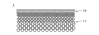
- FIG. 2 is a cross-sectional view of the zeolite membrane complex 1.
- FIG. 3 is an enlarged cross-sectional view showing a part of the zeolite membrane complex 1.
- the zeolite membrane complex 1 includes a porous support 11 and a zeolite membrane 12 formed on the support 11.
- the zeolite membrane 12 does not include, at least, one in which zeolite is formed in a film shape on the surface of the support 11, and one in which zeolite particles are simply dispersed in an organic membrane. Further, the zeolite membrane 12 may contain two or more types of zeolite having different structures and compositions.
- the zeolite membrane 12 is drawn with a thick line.
- the zeolite membrane 12 is shaded in parallel. Further, in FIG. 3, the thickness of the zeolite membrane 12 is drawn thicker than it actually is.
- the support 11 is a porous member that can permeate gas.
- the support 11 is a monolith type in which a plurality of through holes 111 extending in the longitudinal direction (that is, the left-right direction in FIG. 2) are provided on an integrally molded columnar body. It is a support.
- the support 11 has a substantially columnar shape.
- the cross section perpendicular to the longitudinal direction of each through hole 111 ie, cell
- the diameter of the through hole 111 is larger than the actual diameter, and the number of the through hole 111 is smaller than the actual number.
- the zeolite membrane 12 is formed on the inner side surface of the through hole 111, and covers the inner side surface of the through hole 111 over substantially the entire surface.
- the length of the support 11 (that is, the length in the vertical direction in FIG. 1) is, for example, 10 cm to 200 cm.
- the outer diameter of the support 11 is, for example, 0.5 cm to 30 cm.
- the distance between the central axes of the adjacent through holes 111 is, for example, 0.3 mm to 10 mm.
- the surface roughness (Ra) of the support 11 is, for example, 0.1 ⁇ m to 5.0 ⁇ m, preferably 0.2 ⁇ m to 2.0 ⁇ m.
- the shape of the support 11 may be, for example, a honeycomb shape, a flat plate shape, a tubular shape, a cylindrical shape, a columnar shape, a polygonal columnar shape, or the like. When the shape of the support 11 is tubular or cylindrical, the thickness of the support 11 is, for example, 0.1 mm to 10 mm.
- the support 11 is formed of a ceramic sintered body.
- the ceramic sintered body selected as the material of the support 11 include alumina, silica, mullite, zirconia, titania, yttria, silicon nitride, and silicon carbide.
- the support 11 contains at least one of alumina, silica and mullite.
- the support 11 may contain an inorganic binder.
- the inorganic binder at least one of titania, mullite, easily sinterable alumina, silica, glass frit, clay mineral, and easily sinterable cordierite can be used.
- the average pore diameter of the support 11 is, for example, 0.01 ⁇ m to 70 ⁇ m, preferably 0.05 ⁇ m to 25 ⁇ m.
- the average pore diameter of the support 11 in the vicinity of the surface on which the zeolite membrane 12 is formed is 0.01 ⁇ m to 1 ⁇ m, preferably 0.05 ⁇ m to 0.5 ⁇ m.
- the average pore size can be measured by, for example, a mercury porosimeter, a palm porosimeter or a nanopalm porosimeter.
- D5 is, for example, 0.01 ⁇ m to 50 ⁇ m
- D50 is, for example, 0.05 ⁇ m to 70 ⁇ m
- D95 is, for example, 0.1 ⁇ m to 2000 ⁇ m. ..
- the porosity of the support 11 in the vicinity of the surface on which the zeolite membrane 12 is formed is, for example, 20% to 60%.
- the support 11 has, for example, a multilayer structure in which a plurality of layers having different average pore diameters are laminated in the thickness direction.
- the average pore diameter and sintered particle size in the surface layer including the surface on which the zeolite membrane 12 is formed are smaller than the average pore diameter and sintered particle size in the layers other than the surface layer.
- the average pore diameter of the surface layer of the support 11 is, for example, 0.01 ⁇ m to 1 ⁇ m, preferably 0.05 ⁇ m to 0.5 ⁇ m.
- the above materials can be used as the material for each layer.
- the materials of the plurality of layers forming the multilayer structure may be the same or different.
- the zeolite membrane 12 is a porous membrane having pores.
- the zeolite membrane 12 can be used as a separation membrane that separates a specific substance from a mixed gas in which a plurality of types of gases are mixed by utilizing a molecular sieving action.
- other gases are less likely to permeate than the specific gas.
- the permeation amount of the other gas in the zeolite membrane 12 is smaller than the permeation amount of the specific gas.
- the thickness of the zeolite membrane 12 is, for example, 0.05 ⁇ m to 30 ⁇ m, preferably 0.1 ⁇ m to 20 ⁇ m, and more preferably 0.5 ⁇ m to 10 ⁇ m. Thickening the zeolite membrane 12 improves the separation performance. When the zeolite membrane 12 is thinned, the permeation amount increases.
- the surface roughness (Ra) of the zeolite membrane 12 is, for example, 5 ⁇ m or less, preferably 2 ⁇ m or less, more preferably 1 ⁇ m or less, and further preferably 0.5 ⁇ m or less.
- the average pore diameter of the zeolite membrane 12 is preferably 0.2 nm or more and 0.8 nm or less, more preferably 0.3 nm or more and 0.5 nm or less, and further preferably 0.3 nm or more and 0. It is 4 nm or less.
- the average pore diameter of the zeolite membrane 12 is smaller than the average pore diameter of the support 11 in the vicinity of the surface on which the zeolite membrane 12 is formed.
- the arithmetic mean of the minor axis and the major axis of the n-membered ring pores is taken as the average pore diameter.
- the arithmetic mean of the minor axis and the major axis of all the n-membered ring pores is taken as the average pore diameter of the zeolite.
- the n-membered ring is a portion in which the number of oxygen atoms constituting the skeleton forming the pores is n, and each oxygen atom is bonded to a T atom described later to form a cyclic structure.
- the n-membered ring refers to a ring having a through hole (channel), and does not include a ring having no through hole.
- the n-membered ring pores are pores formed by the n-membered ring.
- the average pore size of the zeolite membrane is uniquely determined by the skeletal structure of the zeolite, and is described in "Database of Zeolite Structures" [online] of the International Zeolite Society, Internet ⁇ URL: http: // www. iza-structure. It can be obtained from the values disclosed in org / database />.
- the type of zeolite constituting the zeolite membrane 12 is not particularly limited, but for example, AEI type, AEN type, AFN type, AFV type, AFX type, BEA type, CHA type, DDR type, ERI type, ETL type, FAU type ( X-type, Y-type), GIS-type, LEV-type, LTA-type, MEL-type, MFI-type, MOR-type, PAU-type, RHO-type, SAT-type, SOD-type, and other zeolites may be used.
- zeolites such as AEI type, AFN type, AFV type, AFX type, CHA type, DDR type, ERI type, ETL type, GIS type, LEV type, LTA type, PAU type, RHO type and SAT type.
- the zeolite constituting the zeolite membrane 12 contains, for example, Al as a T atom.
- the atom (T atom) located at the center of the oxygen tetrahedron (TO 4 ) constituting the zeolite is a zeolite composed of silicon (Si) and aluminum (Al), and the T atom is Al.
- SAPO-type zeolite consisting of T atom consisting of Si, Al and P SAPO-type zeolite consisting of T atom consisting of Si, Al and P
- ZnAPSO-type zeolite whose T atom is composed of zinc (Zn), Si, Al, and P can be used.
- a part of the T atom may be replaced with another element.
- Zeolite membrane 12 contains, for example, Si.
- the zeolite membrane 12 may contain, for example, any two or more of Si, Al and P.
- the zeolite membrane 12 may contain an alkali metal.
- the alkali metal is, for example, sodium (Na) or potassium (K).
- the Si / Al ratio in the zeolite membrane 12 is, for example, 1 or more and 100,000 or less.
- the Si / Al ratio is preferably 5 or more, more preferably 20 or more, still more preferably 100 or more, and the higher the ratio, the more preferable.
- the Si / Al ratio in the zeolite membrane 12 can be adjusted by adjusting the mixing ratio of the Si source and the Al source in the raw material solution described later.
- the zeolite membrane 12 is, for example, a DDR type zeolite.
- the zeolite membrane 12 is a zeolite membrane composed of zeolite whose structural code is "DDR" as defined by the International Zeolite Society.
- the intrinsic pore diameter of the zeolite constituting the zeolite membrane 12 is 0.36 nm ⁇ 0.44 nm, and the average pore diameter is 0.40 nm.
- the permeation amount (permeence) of CO 2 of the zeolite membrane 12 at 20 ° C. to 400 ° C. is, for example, 100 nmol / m 2 ⁇ s ⁇ Pa or more.
- the CO 2 permeation amount / CH 4 leakage amount ratio (permeence ratio) of the zeolite membrane 12 at 20 ° C. to 400 ° C. is, for example, 100 or more.
- the permeence and the permeence ratio are those when the partial pressure difference of CO 2 between the supply side and the permeation side of the zeolite membrane 12 is 1.5 MPa.
- a seed crystal used for producing the zeolite membrane 12 is prepared.
- the seed crystal is obtained from, for example, a DDR-type zeolite powder produced by hydrothermal synthesis and obtained from the zeolite powder.
- the zeolite powder may be used as a seed crystal as it is, or a seed crystal may be obtained by processing the powder by pulverization or the like.
- the porous support 11 is immersed in the solution in which the seed crystal is dispersed, and the seed crystal is attached to the support 11.
- the seed crystal is attached to the support 11 by bringing the solution in which the seed crystal is dispersed into contact with the portion of the support 11 on which the zeolite membrane 12 is to be formed.
- a seed crystal adhesion support is produced.
- the seed crystal may be attached to the support 11 by another method.
- the support 11 to which the seed crystal is attached is immersed in the raw material solution.
- the raw material solution is prepared by dissolving, for example, a Si source and a structure defining agent (hereinafter, also referred to as “SDA”) in a solvent.
- SDA structure defining agent
- the composition of the raw material solution is, for example, 1.0SiO 2 : 0.015SDA: 0.12 (CH 2 ) 2 (NH 2 ) 2 .
- Alcohol such as water or ethanol may be used as the solvent of the raw material solution.
- the SDA contained in the raw material solution is, for example, an organic substance.
- As the SDA for example, 1-adamantanamine can be used.
- the DDR-type zeolite membrane 12 is formed on the support 11 by growing the DDR-type zeolite around the seed crystal as a nucleus by hydrothermal synthesis.
- the temperature during hydrothermal synthesis is preferably 120 to 200 ° C, for example 160 ° C.
- the hydrothermal synthesis time is preferably 10 to 100 hours, for example 30 hours.
- the support 11 and the zeolite membrane 12 are washed with pure water. After washing, the support 11 and the zeolite membrane 12 are dried at, for example, 80 ° C. After the support 11 and the zeolite membrane 12 are dried, the zeolite membrane 12 is heat-treated to substantially completely burn and remove the SDA in the zeolite membrane 12 to penetrate the fine pores in the zeolite membrane 12. As a result, the above-mentioned zeolite membrane complex 1 is obtained.
- the flow of separation of the mixed gas by the separation device 2 will be described with reference to FIG.
- the zeolite membrane complex 1 is prepared by preparing the above-mentioned separation device 2 (step S11).
- the supply unit 26 supplies a mixed gas containing a plurality of types of gases having different permeability to the zeolite membrane 12 to the internal space of the outer cylinder 22.
- the mixed gas includes a highly permeable gas and a trace gas.
- the mixed gas may further contain a low permeable gas.
- the trace gas is a component having a molar concentration (mol%) of less than 10 mol% in the mixed gas.
- the trace gas may be one type of gas or two or more types of gas.
- the molar concentration of each kind of trace gas in the mixed gas is less than 10 mol%, and the total molar concentration of the two or more kinds of trace gases in the mixed gas is 10 mol%. May be larger than.
- the total molar concentration is, for example, 1 mol% to 30 mol%, preferably 1 mol% to 10 mol%.
- the main components of the mixed gas are a highly permeable gas and a low permeable gas.
- the highly permeable gas is one type of gas having the highest permeability to the zeolite membrane 12 among the main components of the mixed gas.
- the low-permeability gas is a component obtained by removing the high-permeability gas from the main component of the mixed gas, and the permeability to the zeolite membrane 12 is lower than that of the high-permeability gas.
- the low-permeability gas may be one kind of gas or two or more kinds of gases. In other words, the mixed gas may contain three or more kinds of gases as main components.
- the molar concentration of the highly permeable gas in the mixed gas and the molar concentration of the low permeable gas are 10 mol% or more.
- the molar concentration of the trace gas in the mixed gas is based on the molar concentration of the highly permeable gas in the mixed gas and the molar concentration of the low permeable gas (in the case of two or more types of gas, each type of low permeable gas). Is also low.
- the total content of the highly permeable gas and the low permeable gas in the mixed gas (that is, the content of the main component) is, for example, 70 mol% to 99 mol%, preferably 90 mol% to 99 mol%.
- the highly permeable gas is, for example, H 2 , N 2 , O 2 or CO 2 .
- the low permeable gas contains, for example, one or more of N 2 , air and CH 4.
- the highly permeable gas and the low permeable gas are CO 2 and CH 4 , respectively.
- the trace gas includes a first gas and a second gas.
- the first gas is a low-adsorption gas whose adsorption equilibrium constant with respect to the zeolite membrane 12 is less than 60 times the adsorption equilibrium constant with respect to the zeolite membrane 12 of the highly permeable gas.
- the adsorption equilibrium constant of the first gas with respect to the zeolite membrane 12 is preferably larger than 1 times the adsorption equilibrium constant of the highly permeable gas with respect to the zeolite membrane 12.
- the second gas is a highly adsorptive gas in which the adsorption equilibrium constant with respect to the zeolite membrane 12 is 400 times or more the adsorption equilibrium constant with respect to the zeolite membrane 12 of the highly permeable gas.
- the adsorption equilibrium constant of the highly permeable gas to the zeolite membrane 12 is determined by performing an adsorption test of the highly permeable gas to the zeolite membrane 12 and creating a Langmuir plot from the adsorption isotherm which is the obtained measurement data. It can be calculated. Specifically, first, the same type of zeolite powder as the zeolite membrane 12 (for example, DDR type zeolite powder) is prepared. The Si / Al ratio of the zeolite powder is substantially the same as the Si / Al ratio of the zeolite membrane 12. In addition, a glass container for the adsorption test is prepared, and the weight of the empty glass container is measured.
- a predetermined weight of zeolite powder is contained in the glass container. Then, as the zeolite powder is heated, the inside of the glass container is exhausted to create a vacuum atmosphere (that is, evacuated). As a result, the adsorbent is desorbed from the zeolite powder. After that, the weight of the glass container containing the zeolite powder is measured, and the weight of the zeolite powder is obtained by subtracting the weight of the empty glass container described above from the measured weight.
- the following processing is performed in a state where the temperature of the portion of the glass container containing the zeolite powder is maintained at a predetermined temperature.
- the predetermined temperature is the same temperature as the temperature at which the mixed gas is separated in the separation device 2, and is, for example, room temperature (25 ° C.).
- a predetermined amount of highly permeable gas is introduced into the glass container having a vacuum atmosphere. In the glass container, a part of the highly permeable gas is adsorbed on the zeolite powder. As a result, the pressure inside the glass container is reduced.
- the pressure inside the glass container becomes constant and the adsorption of the highly permeable gas to the zeolite powder is stable
- the pressure P inside the glass container is measured, and the pressure drop due to the adsorption indicates that the highly permeable gas
- the adsorption amount q is calculated. After that, in the same manner as described above, the introduction of the highly permeable gas into the glass container and the acquisition of the pressure P and the adsorption amount q are repeated.
- the measured values of the pressure P and the adsorption amount q are plotted with the horizontal axis as P and the vertical axis as P / q.
- the plotted points are linearly approximated by the least squares method or the like, and the slope a and the intercept b of the approximate straight line are obtained.
- the adsorption equilibrium constant of the highly permeable gas is calculated by dividing the slope a by the intercept b. The calculation of the adsorption equilibrium constants of the first gas and the second gas is also performed in the same manner as described above.
- the molar concentration of the first gas in the mixed gas is higher than the molar concentration of the second gas in the mixed gas.
- the molar concentration of the first gas in the mixed gas is preferably 40 times or more the molar concentration of the second gas in the mixed gas.
- the molar concentration of the first gas in the mixed gas is, for example, 1 mol% to 30 mol%, preferably 1 mol% to 10 mol%.
- the molar concentration of the first gas in the mixed gas may be higher than 30 mol%, but it is preferably 30 mol% or less in consideration of cost, workability and the like.
- the molar concentration of the second gas in the mixed gas is, for example, 0 mol% to 2 mol%, preferably 0 mol% to 0.25 mol%.
- the first gas may be one kind of gas or may contain a plurality of kinds of gases.
- the molar concentration of the first gas in the mixed gas is the total molar concentration of the plurality of types of gases.
- the second gas may be one kind of gas or may contain a plurality of kinds of gases. When the second gas contains a plurality of types of gases, the molar concentration of the second gas in the mixed gas is the total molar concentration of the plurality of types of gases.
- the first gas and the second gas may be an organic gas, an inorganic gas, or a mixed gas of an organic substance and an inorganic substance, respectively.
- at least one of the first gas and the second gas is an organic substance.
- both the first gas and the second gas are organic substances.
- the first gas is, for example, an organic substance composed of carbon (C) and hydrogen (H), or an organic substance composed of carbon (C), hydrogen (H) and oxygen (O), and has a vapor pressure of 50 kPa at 25 ° C.
- the above gas As the first gas, for example, ethylene or propylene is used.
- the second gas is, for example, an organic substance composed of carbon (C) and hydrogen (H), or an organic substance composed of carbon (C), hydrogen (H) and oxygen (O), and has a vapor pressure of 30 kPa at 25 ° C. Less than gas.
- gas for example, vinyl acetate or ethanol is used.
- the trace gas may contain a gas other than the first gas and the second gas. Further, the trace gas may not substantially contain the second gas. In this case, the molar concentration of the second gas in the mixed gas is substantially 0 mol%.
- the second gas is removed from the mixed gas before the mixed gas is supplied to the separation device 2 (step S12).
- the molar concentration of the second gas in the mixed gas is reduced.
- the removal of the second gas in step S12 is performed, for example, by passing the mixed gas through a liquid having a high absorbency of the second gas and allowing the liquid to absorb the second gas.
- the removal of the second gas may be performed by passing the mixed gas through an adsorbent having a high adsorbability of the second gas and adsorbing the second gas on the adsorbent.
- step S12 preferably, the first gas is not intentionally removed from the mixed gas.
- the process intended to remove the first gas from the mixed gas is not performed in step S12.
- the second gas which is a highly adsorptive gas, is selectively removed from the trace gases contained in the mixed gas, thereby pretreating the separation of the highly permeable gas in step S13, which will be described later. Can be simplified.
- the first gas may also be removed.
- the mixed gas after the removal of the second gas is supplied from the supply unit 26 into the outer cylinder 22.
- the pressure (that is, the introduction pressure) of the mixed gas supplied from the supply unit 26 to the internal space of the outer cylinder 22 is, for example, 0.1 MPa to 20.0 MPa.
- the temperature at which the mixed gas is separated is, for example, 10 ° C to 200 ° C.
- the mixed gas supplied from the supply unit 26 to the outer cylinder 22 is introduced into each through hole 111 of the support 11 from the left end in the drawing of the zeolite membrane composite 1 as shown by an arrow 251.
- the highly permeable gas (for example, CO 2 ) in the mixed gas is derived from the outer surface of the support 11 through the zeolite membrane 12 provided on the inner surface of each through hole 111 and the support 11. NS.
- the highly permeable gas is separated from other gases such as the low permeable gas (for example, CH 4) in the mixed gas (step S13).
- the gas derived from the outer surface of the support 11 (hereinafter, referred to as “permeated gas”) is recovered by the second recovery unit 28 via the second discharge port 223 as shown by the arrow 253.
- the pressure (that is, permeation pressure) of the gas recovered by the second recovery unit 28 via the second discharge port 223 is, for example, about 1 atm (0.101 MPa).
- the gas excluding the gas that has permeated through the zeolite membrane 12 and the support 11 has the through holes 111 of the support 11 from the left side to the right side in the drawing.
- the gas is collected by the first collection unit 27 via the first discharge port 222.
- the pressure of the gas recovered by the first recovery unit 27 via the first discharge port 222 is, for example, substantially the same as the introduction pressure.
- the non-permeated gas may include a highly permeable gas that has not permeated the zeolite membrane 12 in addition to the above-mentioned low permeable gas and trace gas.
- the molar concentration of the trace gas in the mixed gas of the second gas is low. Therefore, it is suppressed that the second gas (that is, the highly adsorptive gas) in the trace gas is adsorbed on the pores of the zeolite membrane 12. As a result, it is possible to prevent the second gas adsorbed on the zeolite membrane 12 from inhibiting the permeation of the zeolite membrane 12 of the highly permeable gas. As a result, it is possible to suppress a decrease in the permeation performance of the highly permeable gas due to the zeolite membrane 12 over time.
- the permeation ratio (P40 / P10) in the table is such that in the separation device 2 described above, a mixed gas containing a highly permeable gas (for example, CO 2 ) is supplied to the zeolite membrane composite 1 to obtain the zeolite membrane composite 1. It was determined based on the permeation amount of the permeated gas.
- a mixed gas containing a highly permeable gas for example, CO 2
- the permeation amount ratio (P40 / P10) is obtained by dividing the permeation amount 40 minutes after the start of supply of the mixed gas by the permeation amount 10 minutes after the start of supply of the mixed gas.
- the pressure of the mixed gas supplied from the supply unit 26 was 0.4 MPa, and the pressure (that is, permeation pressure) of the gas recovered by the recovery unit 28 was about 1 atm (0.101 MPa).
- the zeolite membrane 12 of the zeolite membrane composite 1 is a DDR type.
- the highly permeable gas and the low permeable gas contained in the mixed gas are CO 2 and CH 4 , respectively, and the first gas and the second gas in the trace gas I changed the type.
- the molar concentration of the highly permeable gas in the mixed gas was 50 mol%, and the molar concentration of the first gas was changed in the range of 0 mol% to 9 mol%.
- the molar concentration of the second gas was changed in the range of 0.025 mol% to 0.2 mol%.
- the molar concentration of the low-permeability gas in the mixed gas is 100 mol% minus the molar concentrations of the high-permeability gas, the first gas, and the second gas.
- the first gas is ethylene.
- the adsorption equilibrium constant of ethylene with respect to the zeolite membrane 12 (hereinafter, also simply referred to as “adsorption equilibrium constant”) is 9 times the adsorption equilibrium constant of the highly permeable gas. Therefore, the first gas is a low adsorption gas.
- the molar concentration of the first gas in the mixed gas is changed in the range of 1 mol% to 9 mol%.
- the second gas is ethanol.
- the adsorption equilibrium constant of ethanol is 474 times the adsorption equilibrium constant of highly permeable gas. Therefore, the second gas is a highly adsorptive gas.
- the molar concentration of the second gas in the mixed gas is 0.025 mol%.
- the molar concentration of the first gas in the mixed gas is 40 to 360 times the molar concentration of the second gas in the mixed gas.
- the permeation ratio (P40 / P10) was 0.86 to 0.97.
- Examples 4 to 6 are the same as those of Examples 1 to 3 except that the first gas is changed to propylene. Since the adsorption equilibrium constant of propylene is 52 times the adsorption equilibrium constant of the highly permeable gas, the first gas is a low adsorption gas. The permeation ratio (P40 / P10) was 0.88 to 0.96.
- Comparative Example 1 is the same as Examples 1 to 6 except that the trace gas does not contain the first gas (that is, the molar concentration of the first gas in the mixed gas is 0 mol%).
- the permeation ratio (P40 / P10) was 0.76, which was lower than that of Examples 1 to 6.
- the permeation amount ratio is increased as compared with Comparative Example 1, and the permeation performance of the zeolite membrane 12 is stable.
- Examples 7 to 8 are substantially the same as Examples 1 to 6 except that the second gas is changed to vinyl acetate. Since the adsorption equilibrium constant of vinyl acetate is 406 times the adsorption equilibrium constant of the highly permeable gas, the second gas is a low adsorption gas.
- the first gas is ethylene or propylene.
- the molar concentration of the first gas in the mixed gas is 9 mol%.
- the molar concentration of the second gas in the mixed gas is 0.2 mol%.
- the molar concentration of the first gas in the mixed gas is 45 times the molar concentration of the second gas in the mixed gas.
- the permeation ratio (P40 / P10) was 0.77 to 0.81.
- Examples 9 to 10 are the same as those of Examples 7 to 8 except that the molar concentration of the first gas in the mixed gas is changed in the range of 1 mol% to 5 mol%.
- the molar concentration of the first gas in the mixed gas is 5 to 25 times the molar concentration of the second gas in the mixed gas.
- the permeation ratio (P40 / P10) was 0.64 to 0.66.
- Comparative Example 2 is the same as Examples 7 to 10 except that the trace gas does not contain the first gas (that is, the molar concentration of the first gas in the mixed gas is 0 mol%).
- the permeation ratio (P40 / P10) was 0.59, which was lower than that of Examples 7 to 10.
- the permeation amount ratio is increased as compared with Comparative Example 2, and the permeation performance of the zeolite membrane 12 is stable.
- the gas separation method for separating the mixed gas includes the step of preparing the zeolite membrane composite 1 (step S11), supplying the mixed gas to the zeolite membrane composite 1, and supplying the highly permeable gas to the zeolite.
- a step (step S13) of separating from another gas by allowing the membrane composite 1 to permeate is provided.
- the zeolite membrane complex 1 includes a porous support 11 and a zeolite membrane 12 formed on the support 11.
- the mixed gas includes a highly permeable gas and a trace gas having a lower concentration than the highly permeable gas. Of the trace gases, the molar concentration of the first gas in the mixed gas is higher than the molar concentration of the second gas in the mixed gas.
- the adsorption equilibrium constant of the first gas with respect to the zeolite membrane 12 is less than 60 times that of the highly permeable gas.
- the adsorption equilibrium constant of the second gas with respect to the zeolite membrane 12 is 400 times or more that of the highly permeable gas.
- the first gas having a relatively low adsorption equilibrium constant with respect to the zeolite membrane 12 is less than 60 times that of the highly permeable gas (that is, the permeation performance of the zeolite membrane 12 deteriorates with time.
- the molar concentration of the second gas (that is, the highly adsorptive gas) is relatively high, with the adsorption equilibrium constant for the zeolite membrane 12 being 100 times or more that of the highly permeable gas.
- the molar concentration in the mixed gas of the first gas is preferably 40 times or more the molar concentration in the mixed gas of the second gas.
- the highly permeable gas is preferably H 2 , N 2 , O 2 or CO 2.
- H 2 , N 2 , O 2 or CO 2 can be efficiently separated while suppressing a decrease in permeation performance over time.
- the maximum number of membered rings of the zeolite crystal contained in the zeolite membrane 12 is preferably 8. Thereby, in the zeolite membrane complex 1, selective permeation of a gas having a relatively small molecular diameter can be suitably realized.
- At least one of the first gas and the second gas is an organic substance.
- the gas separation method further includes a step (step S12) of removing the second gas from the mixed gas before step S13.
- step S12 the removal of step S12 is performed by selectively removing the second gas (that is, the highly adsorptive gas) without intentionally removing the first gas (that is, the low adsorptive gas). The process can be simplified. As a result, the deterioration of the permeation performance of the zeolite membrane 12 with time can be more easily suppressed.
- the mixed gas further contains a low-permeability gas having a lower permeability to the zeolite membrane 12 than the high-permeability gas, and in the mixed gas, the concentration of the trace gas is lower than the concentration of the low-permeability gas. Is preferable. Thereby, a high permeance ratio can be realized in the separation of the highly permeable gas from the low permeable gas.
- the gas separation methods described above include hydrogen, helium, nitrogen, oxygen, water, water vapor, carbon monoxide, carbon dioxide, nitrogen oxides, ammonia, sulfur oxides, hydrogen sulfide, sulfur fluoride, mercury, alcine, hydrogen cyanide, and sulfide. It is particularly suitable for separating mixed gases containing one or more substances among carbonyl, hydrogens of C1 to C8, organic acids, alcohols, mercaptans, esters, ethers, ketones and aldehydes.
- the mixed gas when the mixed gas is supplied to the zeolite membrane 12 formed on the porous support 11, the molar concentration of the first gas in the mixed gas among the trace gases is the second gas.
- the permeation ratio (P40 / P10) is 0.77 or more and 1.00 or less in a state higher than the molar concentration in the mixed gas.
- the mixed gas contains a highly permeable gas and a trace gas having a concentration lower than that of the highly permeable gas.
- the first gas is a gas whose adsorption equilibrium constant with respect to the zeolite membrane 12 is less than 60 times that of the highly permeable gas.
- the second gas is a gas having an adsorption equilibrium constant with respect to the zeolite membrane 12 that is 400 times or more that of the highly permeable gas.
- the zeolite membrane 12 is particularly suitable for separating mixed gases when the highly permeable gas is H 2 , N 2 , O 2 or CO 2.
- the zeolite membrane 12 is suitable for separating the highly permeable gas from the low permeable gas when the mixed gas further contains a low permeable gas having a higher concentration than the trace gas.
- the gas separation method described above can be changed in various ways.
- step S12 the step of removing the second gas from the mixed gas
- the molar concentration of the first gas in the mixed gas may be less than 40 times the molar concentration of the second gas as long as it is higher than the molar concentration of the second gas in the mixed gas.
- the mixed gas does not necessarily have to contain a low-permeability gas as long as it contains a highly permeable gas and a trace gas.
- the highly permeable gas does not necessarily have to be H 2 , N 2 , O 2 or CO 2 , and may be a gas other than these gases.
- the maximum number of membered rings of the zeolite membrane 12 may be smaller than 8 or larger than 8.
- the zeolite membrane composite 1 may further include a functional membrane or a protective membrane laminated on the zeolite membrane 12.
- a functional film or a protective film may be an inorganic film such as a zeolite film, a silica film or a carbon film, or an organic film such as a polyimide film or a silicone film.
- a substance that easily adsorbs CO 2 may be added to the functional film or the protective film laminated on the zeolite membrane 12.
- the gas separation method of the present invention can be used in various fields in which gas separation is performed.
Landscapes
- Chemical & Material Sciences (AREA)
- Organic Chemistry (AREA)
- Chemical Kinetics & Catalysis (AREA)
- Analytical Chemistry (AREA)
- Inorganic Chemistry (AREA)
- Engineering & Computer Science (AREA)
- Oil, Petroleum & Natural Gas (AREA)
- Life Sciences & Earth Sciences (AREA)
- Geology (AREA)
- Water Supply & Treatment (AREA)
- General Life Sciences & Earth Sciences (AREA)
- General Chemical & Material Sciences (AREA)
- Materials Engineering (AREA)
- Separation Using Semi-Permeable Membranes (AREA)
Abstract
Description
[関連出願の参照]
本願は、2020年3月18日に出願された日本国特許出願JP2020-047802からの優先権の利益を主張し、当該出願の全ての開示は、本願に組み込まれる。


11 支持体
12 ゼオライト膜
S11~S13 ステップ
Claims (11)
- 混合ガスを分離するガス分離方法であって、
a)多孔質の支持体と前記支持体上に形成されたゼオライト膜とを備えるゼオライト膜複合体を準備する工程と、
b)高透過性ガスと、前記高透過性ガスよりも低濃度の微量ガスとを含む混合ガスを、前記ゼオライト膜複合体に供給し、前記高透過性ガスを前記ゼオライト膜複合体を透過させることにより他のガスから分離する工程と、
を備え、
前記微量ガスのうち、前記ゼオライト膜に対する吸着平衡定数が前記高透過性ガスの60倍未満である第1ガスの前記混合ガス中におけるモル濃度は、前記ゼオライト膜に対する吸着平衡定数が前記高透過性ガスの400倍以上である第2ガスの前記混合ガス中におけるモル濃度よりも高い。 - 請求項1に記載のガス分離方法であって、
前記第1ガスの前記混合ガス中におけるモル濃度は、前記第2ガスの前記混合ガス中におけるモル濃度の40倍以上である。 - 請求項1または2に記載のガス分離方法であって、
前記高透過性ガスは、水素、窒素、酸素または二酸化炭素である。 - 請求項1ないし3のいずれか1つに記載のガス分離方法であって、
前記第1ガスおよび前記第2ガスのうち少なくとも一方のガスは有機物である。 - 請求項1ないし4のいずれか1つに記載のガス分離方法であって、
前記ゼオライト膜に含まれるゼオライト結晶の最大員環数は8である。 - 請求項1ないし5のいずれか1つに記載のガス分離方法であって、
前記b)工程よりも前に、前記混合ガスから前記第2ガスを除去する工程をさらに備える。 - 請求項1ないし6のいずれか1つに記載のガス分離方法であって、
前記混合ガスは、前記ゼオライト膜に対する透過性が前記高透過性ガスよりも低い低透過性ガスをさらに含み、
前記混合ガスにおいて、前記微量ガスの濃度は前記低透過性ガスの濃度よりも低い。 - 請求項1ないし7のいずれか1つに記載のガス分離方法であって、
前記混合ガスは、水素、ヘリウム、窒素、酸素、水、水蒸気、一酸化炭素、二酸化炭素、窒素酸化物、アンモニア、硫黄酸化物、硫化水素、フッ化硫黄、水銀、アルシン、シアン化水素、硫化カルボニル、C1~C8の炭化水素、有機酸、アルコール、メルカプタン類、エステル、エーテル、ケトンおよびアルデヒドのうち、1種類以上の物質を含む。 - 多孔質の支持体上に形成されたゼオライト膜であって、
高透過性ガスと、前記高透過性ガスよりも低濃度の微量ガスと、を含む混合ガスが供給された際に、前記微量ガスのうち、前記ゼオライト膜に対する吸着平衡定数が前記高透過性ガスの60倍未満である第1ガスの前記混合ガス中におけるモル濃度が、前記ゼオライト膜に対する吸着平衡定数が前記高透過性ガスの400倍以上である第2ガスの前記混合ガス中におけるモル濃度よりも高い状態で、透過量比P40/P10は、0.77以上かつ1.00以下である。 - 請求項9に記載のゼオライト膜であって、
前記高透過性ガスは、水素、窒素、酸素または二酸化炭素である。 - 請求項9または10に記載のゼオライト膜であって、
前記混合ガスは、前記ゼオライト膜に対する透過性が前記高透過性ガスよりも低い低透過性ガスをさらに含み、
前記混合ガスにおいて、前記微量ガスの濃度は前記低透過性ガスの濃度よりも低い。
Priority Applications (3)
| Application Number | Priority Date | Filing Date | Title |
|---|---|---|---|
| BR112022018448A BR112022018448A2 (pt) | 2020-03-18 | 2021-02-12 | Método de separação de gás e membrana de zeólito |
| JP2022508142A JP7313544B2 (ja) | 2020-03-18 | 2021-02-12 | ガス分離方法およびゼオライト膜 |
| US17/931,925 US20230026226A1 (en) | 2020-03-18 | 2022-09-14 | Gas separation method and zeolite membrane |
Applications Claiming Priority (2)
| Application Number | Priority Date | Filing Date | Title |
|---|---|---|---|
| JP2020-047802 | 2020-03-18 | ||
| JP2020047802 | 2020-03-18 |
Related Child Applications (1)
| Application Number | Title | Priority Date | Filing Date |
|---|---|---|---|
| US17/931,925 Continuation US20230026226A1 (en) | 2020-03-18 | 2022-09-14 | Gas separation method and zeolite membrane |
Publications (1)
| Publication Number | Publication Date |
|---|---|
| WO2021186974A1 true WO2021186974A1 (ja) | 2021-09-23 |
Family
ID=77770830
Family Applications (1)
| Application Number | Title | Priority Date | Filing Date |
|---|---|---|---|
| PCT/JP2021/005278 WO2021186974A1 (ja) | 2020-03-18 | 2021-02-12 | ガス分離方法およびゼオライト膜 |
Country Status (4)
| Country | Link |
|---|---|
| US (1) | US20230026226A1 (ja) |
| JP (1) | JP7313544B2 (ja) |
| BR (1) | BR112022018448A2 (ja) |
| WO (1) | WO2021186974A1 (ja) |
Citations (3)
| Publication number | Priority date | Publication date | Assignee | Title |
|---|---|---|---|---|
| JP2017100087A (ja) * | 2015-12-02 | 2017-06-08 | 日本碍子株式会社 | 分離膜構造体及びパラキシレンの濃縮方法 |
| JP2019181456A (ja) * | 2018-03-30 | 2019-10-24 | 日本碍子株式会社 | ゼオライト膜複合体、ゼオライト膜複合体の製造方法、および、分離方法 |
| JP2020032383A (ja) * | 2018-08-31 | 2020-03-05 | 東京瓦斯株式会社 | 評価方法及び評価システム |
-
2021
- 2021-02-12 JP JP2022508142A patent/JP7313544B2/ja active Active
- 2021-02-12 WO PCT/JP2021/005278 patent/WO2021186974A1/ja active Application Filing
- 2021-02-12 BR BR112022018448A patent/BR112022018448A2/pt unknown
-
2022
- 2022-09-14 US US17/931,925 patent/US20230026226A1/en active Pending
Patent Citations (3)
| Publication number | Priority date | Publication date | Assignee | Title |
|---|---|---|---|---|
| JP2017100087A (ja) * | 2015-12-02 | 2017-06-08 | 日本碍子株式会社 | 分離膜構造体及びパラキシレンの濃縮方法 |
| JP2019181456A (ja) * | 2018-03-30 | 2019-10-24 | 日本碍子株式会社 | ゼオライト膜複合体、ゼオライト膜複合体の製造方法、および、分離方法 |
| JP2020032383A (ja) * | 2018-08-31 | 2020-03-05 | 東京瓦斯株式会社 | 評価方法及び評価システム |
Also Published As
| Publication number | Publication date |
|---|---|
| JP7313544B2 (ja) | 2023-07-24 |
| US20230026226A1 (en) | 2023-01-26 |
| JPWO2021186974A1 (ja) | 2021-09-23 |
| BR112022018448A2 (pt) | 2022-11-01 |
Similar Documents
| Publication | Publication Date | Title |
|---|---|---|
| WO2020195105A1 (ja) | ゼオライト膜複合体、ゼオライト膜複合体の製造方法、ゼオライト膜複合体の処理方法、および、分離方法 | |
| JP7398578B2 (ja) | ガス分離方法およびガス分離装置 | |
| JP7220087B2 (ja) | ゼオライト膜複合体、ゼオライト膜複合体の製造方法、および、分離方法 | |
| US20230018523A1 (en) | Gas separation method and zeolite membrane | |
| JP7213977B2 (ja) | ゼオライト膜複合体、ゼオライト膜複合体の製造方法、分離装置、膜型反応装置および分離方法 | |
| JP2019150823A (ja) | ゼオライト膜複合体、および、ゼオライト膜複合体の製造方法 | |
| US20210322932A1 (en) | Zeolite membrane composite, method of producing zeolite membrane composite, and separation method | |
| US20240033691A1 (en) | Support, zeolite membrane complex, method of producing zeolite membrane complex, and separation method | |
| WO2022018910A1 (ja) | 分離膜複合体および分離方法 | |
| WO2021186974A1 (ja) | ガス分離方法およびゼオライト膜 | |
| WO2019187640A1 (ja) | ゼオライト膜複合体、ゼオライト膜複合体の製造方法、および、分離方法 | |
| WO2021240917A1 (ja) | 分離膜複合体、分離膜複合体の製造方法および分離方法 | |
| US20240181399A1 (en) | Processing method of separation membrane complex and processing apparatus for separation membrane complex | |
| WO2023085372A1 (ja) | ゼオライト膜複合体および膜反応装置 | |
| WO2023162854A1 (ja) | ゼオライト膜複合体、ゼオライト膜複合体の製造方法および分離方法 | |
| JP7444990B2 (ja) | 分離システム | |
| WO2023238557A1 (ja) | 分離装置の運転方法および分離装置 | |
| WO2023162525A1 (ja) | ゼオライト膜複合体および分離方法 |
Legal Events
| Date | Code | Title | Description |
|---|---|---|---|
| 121 | Ep: the epo has been informed by wipo that ep was designated in this application |
Ref document number: 21771420 Country of ref document: EP Kind code of ref document: A1 |
|
| ENP | Entry into the national phase |
Ref document number: 2022508142 Country of ref document: JP Kind code of ref document: A |
|
| REG | Reference to national code |
Ref country code: BR Ref legal event code: B01A Ref document number: 112022018448 Country of ref document: BR |
|
| NENP | Non-entry into the national phase |
Ref country code: DE |
|
| ENP | Entry into the national phase |
Ref document number: 112022018448 Country of ref document: BR Kind code of ref document: A2 Effective date: 20220915 |
|
| 122 | Ep: pct application non-entry in european phase |
Ref document number: 21771420 Country of ref document: EP Kind code of ref document: A1 |