WO2020255568A1 - 回転体装着装置、油捕集装置及びレンジフード - Google Patents
回転体装着装置、油捕集装置及びレンジフード Download PDFInfo
- Publication number
- WO2020255568A1 WO2020255568A1 PCT/JP2020/018239 JP2020018239W WO2020255568A1 WO 2020255568 A1 WO2020255568 A1 WO 2020255568A1 JP 2020018239 W JP2020018239 W JP 2020018239W WO 2020255568 A1 WO2020255568 A1 WO 2020255568A1
- Authority
- WO
- WIPO (PCT)
- Prior art keywords
- rotating body
- attachment
- detachment
- power shaft
- mounting device
- Prior art date
Links
Images


Classifications
-
- F—MECHANICAL ENGINEERING; LIGHTING; HEATING; WEAPONS; BLASTING
- F24—HEATING; RANGES; VENTILATING
- F24C—DOMESTIC STOVES OR RANGES ; DETAILS OF DOMESTIC STOVES OR RANGES, OF GENERAL APPLICATION
- F24C15/00—Details
- F24C15/20—Removing cooking fumes
- F24C15/2078—Removing cooking fumes movable
- F24C15/2092—Removing cooking fumes movable extendable or pivotable
-
- F—MECHANICAL ENGINEERING; LIGHTING; HEATING; WEAPONS; BLASTING
- F16—ENGINEERING ELEMENTS AND UNITS; GENERAL MEASURES FOR PRODUCING AND MAINTAINING EFFECTIVE FUNCTIONING OF MACHINES OR INSTALLATIONS; THERMAL INSULATION IN GENERAL
- F16D—COUPLINGS FOR TRANSMITTING ROTATION; CLUTCHES; BRAKES
- F16D1/00—Couplings for rigidly connecting two coaxial shafts or other movable machine elements
- F16D1/10—Quick-acting couplings in which the parts are connected by simply bringing them together axially
- F16D1/108—Quick-acting couplings in which the parts are connected by simply bringing them together axially having retaining means rotating with the coupling and acting by interengaging parts, i.e. positive coupling
- F16D1/116—Quick-acting couplings in which the parts are connected by simply bringing them together axially having retaining means rotating with the coupling and acting by interengaging parts, i.e. positive coupling the interengaging parts including a continuous or interrupted circumferential groove in the surface of one of the coupling parts
-
- F—MECHANICAL ENGINEERING; LIGHTING; HEATING; WEAPONS; BLASTING
- F24—HEATING; RANGES; VENTILATING
- F24C—DOMESTIC STOVES OR RANGES ; DETAILS OF DOMESTIC STOVES OR RANGES, OF GENERAL APPLICATION
- F24C15/00—Details
- F24C15/20—Removing cooking fumes
-
- F—MECHANICAL ENGINEERING; LIGHTING; HEATING; WEAPONS; BLASTING
- F24—HEATING; RANGES; VENTILATING
- F24C—DOMESTIC STOVES OR RANGES ; DETAILS OF DOMESTIC STOVES OR RANGES, OF GENERAL APPLICATION
- F24C15/00—Details
- F24C15/20—Removing cooking fumes
- F24C15/2035—Arrangement or mounting of filters
-
- F—MECHANICAL ENGINEERING; LIGHTING; HEATING; WEAPONS; BLASTING
- F24—HEATING; RANGES; VENTILATING
- F24C—DOMESTIC STOVES OR RANGES ; DETAILS OF DOMESTIC STOVES OR RANGES, OF GENERAL APPLICATION
- F24C15/00—Details
- F24C15/20—Removing cooking fumes
- F24C15/2071—Removing cooking fumes mounting of cooking hood
-
- F—MECHANICAL ENGINEERING; LIGHTING; HEATING; WEAPONS; BLASTING
- F24—HEATING; RANGES; VENTILATING
- F24F—AIR-CONDITIONING; AIR-HUMIDIFICATION; VENTILATION; USE OF AIR CURRENTS FOR SCREENING
- F24F7/00—Ventilation
- F24F7/007—Ventilation with forced flow
- F24F7/013—Ventilation with forced flow using wall or window fans, displacing air through the wall or window
-
- F—MECHANICAL ENGINEERING; LIGHTING; HEATING; WEAPONS; BLASTING
- F24—HEATING; RANGES; VENTILATING
- F24F—AIR-CONDITIONING; AIR-HUMIDIFICATION; VENTILATION; USE OF AIR CURRENTS FOR SCREENING
- F24F7/00—Ventilation
- F24F7/04—Ventilation with ducting systems, e.g. by double walls; with natural circulation
- F24F7/06—Ventilation with ducting systems, e.g. by double walls; with natural circulation with forced air circulation, e.g. by fan positioning of a ventilator in or against a conduit
Definitions
- the present invention relates to a rotating body mounting device in a range hood or the like.
- the range hood includes a rotating body such as a propeller fan, a sirocco fan, and a turbo fan for exhausting air, and a rotating body such as a grease filter for collecting oil, dust, and the like.
- These rotating bodies are rotated by a motor to recover the exhaust gas and the oil contained in the exhaust gas. Since oil and the like derived from oil smoke generated by cooking easily adhere to rotating bodies such as fans and grease filters, regular cleaning is required. Therefore, in order to clean the dirty rotating body, it is necessary to periodically remove the rotating body from the drive shaft.
- the boss cylinder and the impeller main body can be separated by removing a mounting knob with a screw called a spinner.
- An object of the present invention is to provide a rotating body mounting device with improved workability for attaching and detaching to and from a power shaft.
- a aspect of claim 1 of the present invention is a rotating body mounting device 30 inserted into a power shaft 20 including a rotating body and a mounting device 302, in which the mounting device 302 is an insertion hole into which the power shaft 20 is inserted.
- the rotating body mounting device is attached to the power shaft 20 on the side where the power shaft 20 is not inserted into the mounting device 302 with reference to the rotating body. It has a power shaft attachment / detachment mechanism operation unit to be attached / detached, and the rotating body is attached / detached from the rotating body mounting device 30 on the side where the power shaft 20 is inserted into the mounting device 302 with reference to the rotating body.
- the problem was solved by using a rotating body mounting device 30 having a mechanism operating unit.
- the rotating body mounting device 30 including the rotating body and the mounting device 302 can be easily removed from the power shaft 20 while being integrated. Further, by providing the rotating body attachment / detachment mechanism operation unit of the mounting device on the side where the power shaft 20 is inserted into the mounting device 302 with the rotating body as a reference, the rotating body mounting device 30 is mounted on the power shaft 20.
- the rotating body attachment / detachment mechanism operation part of the mounting device is located at the back of the rotating body and is out of reach. Therefore, the rotating body mounting device 30 is configured so that the rotating body attachment / detachment mechanism operation unit of the mounting device cannot be operated until the rotating body mounting device 30 is removed as described above. This makes it possible to prevent accidentally operating the rotating body attachment / detachment mechanism operation unit of the mounting device while the rotating body mounting device 30 is mounted on the power shaft 20.
- the mounting device 302 includes a detachable device 40 having the power shaft attachment / detachment mechanism operation unit and a rotating body holding device 50 having the rotating body attachment / detachment mechanism operation unit 5011.
- the rotating body mounting device 30 described in 1 may be used.
- the attachment / detachment device 40 includes a boss cylinder 431 to be inserted into the rotating body, and the rotating body attachment / detachment mechanism operation unit 5011 of the rotating body holding device 50 is the boss cylinder.
- the rotating body mounting device 30 according to claim 2, characterized in that the 431 is provided so as to hold and release the 431.
- the rotating body mounting device 30 can be disassembled into three members, the attaching / detaching device 40, the rotating body, and the rotating body holding device 50, by one operation of the rotating body attaching / detaching mechanism operation unit 5011. Further, it is possible to prevent the attachment / detachment device 40 and the rotating body holding device 50 from being accidentally separated from each other while the rotating body mounting device 30 is mounted on the power shaft 20.
- the attachment / detachment device 40 is provided with a tapered surface 4312 whose diameter is reduced toward the rotating body side, and the urging portion of the rotating body holding device 50 is tapered.
- the urging portion of the rotating body pressing device 50 can have two functions of holding and releasing the boss cylinder 431 and pressing the rotating body.
- the rotating body has a concave portion and / or a convex portion on the mounting surface of the detachable device and / or the rotating body holding device so as to be fitted therein.
- the rotating body mounting device 30 according to any one of claims 2 to 5, wherein the attachment / detachment device 40 and / or the rotating body holding device 50 is provided with a convex portion and / or a concave portion. May be.
- the rotating body when the rotating body is a grease filter (rotating body) 301, there are a front surface and a back surface, and when the rotating body is a sirocco fan, there are an upper surface and a lower surface. If the rotating body is not mounted on the correct surface of the attachment / detachment device 40 and the rotating body holding device 50, the rotating body may not function properly. In such a case, the rotating body erroneously turns upside down or upside down by having the detachable device side concave portion or the convex portion that fits into the rotating body side convex portion or the concave portion provided in the detachable device 40. It is possible to prevent the rotating body from being attached.
- the rotating body erroneously turns upside down or upside down by having the detachable device side concave portion or the convex portion that fits into the rotating body side convex portion or the concave portion provided in the detachable device 40. It is possible to prevent the rotating body from being attached.
- the rotating body pressing device may be provided with a rotating body side convex portion or a concave portion that fits into the rotating body pressing device side concave portion or the convex portion provided on the rotating body.
- the concave and / or convex portions of the rotating body are curved so that the mounting surface is curved so as to be a convex portion on the attachment / detachment device 40 side (curvature so as to be a concave portion when viewed from the rotating body holding device 50 side).
- the concave portion or the convex portion may be provided only on the attachment / detachment device 40 side of the mounting surface or only on the rotating body holding device 50 side.
- attachment / detachment device 40 side and the rotating body holding device 50 side may be provided with the concave / or convex portion so as to fit into the concave / or convex portion provided on the mounting surface of the rotating body.
- shape of the concave portion and the convex portion can be various.
- the rotating body has at least one engaging mechanism (3016, 3018), and the attaching / detaching device 40 or the rotating body holding device 50 has the engaging mechanism.
- the rotating body mounting device 30 according to any one of claims 2 to 6 having an engaged mechanism (434, 435) that engages with (3016, 3018) may be used. This has made it possible to reliably stop the rotating body from rotating.
- an oil trap including a rotating body mounting device 30 of the above aspect, a power device 4 for rotating the rotating body mounting device 30, and an oil collecting member 5 for collecting oil. It may be used as a collector. As a result, by adding the oil collecting member 5, it becomes easier to use the rotating body mounting device 30 even in an environment where oil easily adheres.
- the range hood 1 may be provided with the rotating body mounting device 30 or the oil collecting device of the above aspect.
- the rotating body mounting device and the oil collecting device included in the present invention can be used for various rotating bodies, and among them, the rotating body used in the range hood 1 includes a grease filter, a fan, and the like. , It was clarified that it can also be used for these.
- the rotating body mounting device including the rotating body and the mounting device can be attached to and detached from the power shaft in an integrated state, so that workability is improved.
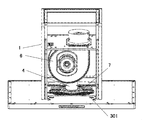
- FIG. 1 Perspective view from the bottom side of the range hood with the current plate removed A perspective view from above of the range hood with a part of the blower box removed for explanation.
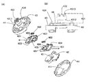
- FIG. 1 Perspective view of (A) grease filter drive motor (power unit) according to the first embodiment
- FIG. 1 Perspective view of (B) grease filter drive motor (power unit) according to the first embodiment
- FIG. 1 Perspective view of (B) grease filter drive motor (power unit) according to the first embodiment
- FIG. 1 Perspective view of (A) grease filter drive motor (power unit) according to the first embodiment
- FIG. 1 Perspective view of (A) grease filter drive motor (power unit) according to the first embodiment
- FIG. 1 Perspective view of (A) grease filter drive motor (power unit) according to the first embodiment
- FIG. 1 Perspective view of (A) grease filter drive motor (power unit) according to the first embodiment
- FIG. 1 Perspective view of (A) grease filter drive motor (power unit) according to the first embodiment
- FIG. 1 Perspective view of (A) grease filter drive motor (power unit) according
- Exploded view of the rotating body holding device according to the second embodiment (A) Enlarged view of the boss cylinder (B) A perspective view showing a holding relationship between the boss cylinder and the rotating body attachment / detachment mechanism according to the second embodiment.
- the conceptual diagram which shows the relationship between the boss cylinder holding member (bar spring which has a clamping action) and the tip portion of a boss cylinder which concerns on Example 2.
- the conceptual diagram which shows the mode of the urging part which concerns on Example 2.
- Exploded view showing the mounting relationship of the attachment / detachment device, the grease filter (rotating body), and the rotating body holding device according to the second embodiment.
- A) Perspective view (B) Perspective view of the rotating body holding device according to the third embodiment with the upper cover removed.
- Example 1 is an example in which the present invention is applied to the grease filter (rotating body) 301 of the range hood 1.
- FIG. 1 is a perspective view from the bottom surface side of the range hood 1 from which the straightening vane is removed, and shows a state in which the straightening vane covering the lower surface of the range hood 1 is removed.
- a grease filter (rotating body) 301 corresponding to a rotating body is attached by an attachment device 302.
- a bell mouth (oil collecting member) 5 that also functions as an oil collecting member is mounted around the grease filter (rotating body) 301.
- the rotating body mounting device 30 is composed of at least two members, a grease filter (rotating body) 301 and a mounting device 302.
- the mounting device 302 is a member located on both sides of the grease filter (rotating body) 301, and in FIG. 1, which is a perspective view from the bottom surface side, the lower side of the mounting device 302 is visible.
- the power shaft attachment / detachment mechanism operation unit 303 of the attachment device projects from both sides of the attachment device 302.
- the rotating body mounting device 30 When the power shaft attachment / detachment mechanism operation unit 303 of the attachment device is pressed, the rotating body mounting device 30 is disengaged from the power shaft (not shown) inserted in the rotating body mounting device 30.
- the specific structure is the same as that of the “1 attachment / detachment device A power shaft attachment / detachment mechanism” of the second embodiment described later. Since the rotating body mounting device 30 composed of the grease filter (rotating body) 301 and the mounting device 302 can be removed from the power shaft 20 while being integrated, if the worker holds the mounting device 302, the grease filter (rotating body) The grease filter (rotating body) 301 does not come off and fall even if the rotating body) 301 is not particularly supported.
- FIG. 2 is a perspective view from the upper side of the range hood 1 in which a part of the blower box is removed for explanation.
- a fan casing 6 is provided in the blower box, and a fan and a motor for driving the fan are housed in the fan casing 6.
- the grease filter drive motor (power device) 4 that drives the grease filter (rotating body) 301 is fixed on the grease filter drive motor crosspiece 7.
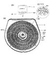
- FIG. 3 is a perspective view of (A) the grease filter drive motor (power device) 4 according to the first embodiment, and (B) the grease filter (rotating body) 301 and the mounting device 302 are mounted on the grease filter drive motor (power device) 4 side. It is a perspective view seen from the view and (C) is an enlarged perspective view inside the one-point chain line circle of FIG. 3 (B).
- the power shaft 20 of the grease filter drive motor (power device) 4 shown in FIG. 3 (A) is inserted into the power shaft insertion hole 305 drawn in FIGS. 3 (B) and 3 (C). Then, the pair of drive pins 201 provided on the power shaft 20 are fitted into the drive pin receiving grooves 306 provided near the entrance of the power shaft insertion hole 305. A plurality of pairs of drive pin receiving grooves 306 are provided so that the power shaft 20 can be fitted regardless of the circumferential direction in which the power shaft 20 is inserted into the power shaft insertion hole 305.
- the mounting device 302 is provided with a pair of rotating body attachment / detachment mechanism operation units 3071 of the mounting device, and a pair of rotating body pressing stoppers 3072 are grease filters (rotating). Body) It sticks out on the upper surface of 301. Further, a bell mouth (oil collecting member) 5 is arranged around the grease filter (rotating body) 301, and functions as an oil collecting member as described later.
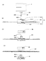
- FIG. 4 is a front view (A), a cross-sectional view (B), and (C) a cross-sectional view showing the position of the rotating body pressing stopper 3072 when the rotating body is removed, and a grease filter of the rotating body mounting device 30 according to the first embodiment.
- a conceptual diagram showing a positional relationship between the (rotating body) 301 and the mounting device insertion hole 3011 is shown.
- the rotating body mounting device 30 is an assembly of two constituent members, a grease filter (rotating body) 301 and a mounting device 302.
- the rotating body attachment / detachment mechanism 307 is composed of a rotating body attachment / detachment mechanism operation unit 3071 of the attachment device and a rotating body pressing stopper 3072, and is a grease filter (rotating body) 301 which is a constituent member of the rotating body attaching device 30 for cleaning or the like. Is removed from the mounting device 302 by pressing the rotating body attachment / detachment mechanism operation unit 3071 of the mounting device.
- FIG. 4C In the state of FIG. 4B showing the state before pressing the rotating body attachment / detachment mechanism operation unit 3071 of the mounting device, when the rotating body attachment / detachment mechanism operation unit 3071 of the mounting device is pressed, it rotates as shown in FIG. 4C.
- the body pressing stopper 3072 is configured to move into the mounting device 302 and completely fit within the mounting device 302.
- the moving mechanism of the rotating body pressing stopper 3072 is not shown, the rotating body attaching / detaching mechanism operation unit 3071 of the mounting device and the rotating body pressing stopper 3072 are connected by a link mechanism, or the rotating body attaching / detaching mechanism of the mounting device.
- the type of the moving mechanism is not limited, such as one in which an electromagnetic relay that operates based on the operation of the operating unit 3071 is provided and the rotating body pressing stopper 3072 moves.
- the center of the grease filter (rotating body) 301 is as shown in FIG. 4 (C).
- the mounting device 302 is pulled out from the mounting device insertion hole 3011 provided in the above.
- the grease filter (rotating body) 301 may be attached to the attachment device 302 in the reverse order.
- the power shaft 20 is inserted into the mounting device 302 from the power shaft insertion hole 305 side of FIG. 4A, and the mounting device 302 is inserted into the mounting device 302 with reference to the grease filter (rotating body) 301.
- the power shaft attachment / detachment mechanism operation unit 303 of the attachment device for attaching / detaching the attachment device 302 to / from the power shaft 20 is provided on the side where the attachment device 302 is not inserted.
- the power shaft attachment / detachment mechanism operation unit 303 of the attachment device is located at such a position, it can be easily reached from the lower side of the range hood 1 as shown in FIG. Even in the range hood 1 in which the power shaft 20 is provided horizontally, the power shaft attachment / detachment mechanism operation unit 303 of the mounting device can be easily reached.
- the mounting device 302 has a rotating body attachment / detachment mechanism operation unit 3071 of the mounting device on the side where the power shaft 20 is inserted into the mounting device 302 with reference to the grease filter (rotating body) 301. If the rotating body attachment / detachment mechanism operation unit 3071 of the mounting device is located at such a position, the grease filter (rotating body) 301 cannot be removed from the mounting device 302 until after the rotating body mounting device 30 has been removed from the power shaft 20. .. As can be seen from FIG.
- the rotating body attachment / detachment mechanism operation unit 3071 of the mounting device is located in a position where it cannot be seen and reached from under the range hood 1, and the operator mistakenly operates the rotating body attachment / detachment mechanism operation unit of the mounting device.
- the 3071 cannot be operated.
- the reason why the grease filter (rotating body) 301 can be removed from the mounting device 302 is that the grease filter (rotating body) 301 can be easily cleaned by removing it. Further, when the disposable type grease filter (rotating body) 301 is used when it becomes dirty, it can be easily replaced because there is a rotating body attachment / detachment mechanism operation unit 3071 of the mounting device.
- the rotating body has been described as a grease filter (rotating body) 301, but it may be used for a fan used in the range hood 1.
- the present invention is a general-purpose technique that can be used in a rotating body other than a range hood. The same applies to the following examples.
- the bell mouth (oil collecting member) 5 illustrated in FIGS. 1 and 3 (B) has an annular groove so that oil flying by centrifugal force can be collected from the grease filter (rotating body) 301. It also functions as a grease collecting member. The accumulated oil can be easily disposed of by simply removing the bell mouth (oil collecting member) 5.
- an oil collecting member for collecting oil flying from the fan by centrifugal force may be provided.
- an oil collecting member for collecting oil dripping from the casing of the fan or the like may be provided. The shape and installation position of the oil collecting member can be changed as appropriate depending on which member the oil drips from and the position where the oil drips.
- the oil collecting member is not limited to the bell mouth (oil collecting member) 5, and various members are included in the present invention. Further, a discharge pipe for discharging oil may be provided in the oil collecting member. In any case, in an environment where the oil adheres to the rotating body, the oil can be easily treated by providing the oil collecting member.
- the second embodiment is an embodiment in which the grease filter (rotating body) 301 used for the range hood 1 is used as a rotating body.
- the difference from the first embodiment is that the attachment device 302 can be further separated into the attachment / detachment device 40 and the rotating body holding device 50.
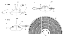
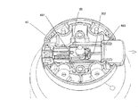
- 5A and 5B show a front view of (A) a grease filter drive motor (power device) 4 according to a second embodiment, (B) a front view of a rotating body mounting device 30, and (C) a rotating body holder of the rotating body mounting device 30.
- An exploded front view with the device 50 removed, and (D) an exploded front view with the rotating body holding device 50 and the grease filter (rotating body) 301 removed from the rotating body mounting device 30 are shown.
- FIG. 5A shows the first and second power shaft holding levers (403, 404), which are constituent members of the power shaft attachment / detachment mechanism, as described in “1 Attachment / detachment device A power shaft attachment / detachment mechanism” described later.
- the reduced diameter portion 202 of the held power shaft 20 is shown.
- the power shaft 20 is inserted through the boss cylinder power shaft insertion hole 433 shown in FIG. 5B, and the rotating body mounting device 30 is mounted on the power shaft 20.
- the rotating body mounting device 30 (rotating body holding device 50) can be operated by operating the power shaft attachment / detachment mechanism operation unit 401 of the attachment / detachment device of FIG. 5 (B).
- a grease filter (rotating body) 301 and three members of the attachment / detachment device 40) are integrated and can be removed from the power shaft 20.
- the grease filter (rotating body) 301 is pressed by operating the rotating body attachment / detachment mechanism operation unit 5011 of the rotating body holding device.
- the rotating body holding device 50 is removed, and the grease filter (rotating body) 301 can be removed.
- the rotating body attachment / detachment mechanism operation unit 5011 of the rotating body holding device is provided on the side where the power shaft 20 is inserted into the rotating body mounting device 30 with reference to the grease filter (rotating body) 301.
- the grease filter (rotating body) 301 can be attached to and detached from the rotating body mounting device 30.
- the grease filter (rotating body) 301 becomes an obstacle and the rotating body attachment / detachment mechanism operation unit 5011 of the rotating body holding device cannot be operated. It is the same as Example 1.
- the power shaft attachment / detachment mechanism operation unit 401 of the attachment / detachment device is provided in the attachment / detachment device 40, and when this is operated, the entire rotating body mounting device 30 is separated from the power shaft 20, and the grease filter (rotating body) 301 and the attachment / detachment device are removed.
- the three members of the 40 and the rotating body holding device 50 can be removed as a unit.
- the power shaft attachment / detachment mechanism operation unit 401 of the attachment / detachment device is arranged so as to be visible to the operator by simply removing the straightening vane from the range hood 1. It is configured for easy operation.
- FIG. 6 is an exploded view (A) and a front view of (B) a boss member 43 of the attachment / detachment device 40 according to the second embodiment.
- the attachment / detachment device 40 includes a power shaft attachment / detachment mechanism including a first power shaft holding lever 403, a second power shaft holding lever 404, and a power shaft holding lever urging member 402.
- the first power shaft holding lever 403 and the second power shaft holding lever 404 each include a power shaft attachment / detachment mechanism operation unit 401, a holding lever power shaft insertion hole 405, and a power shaft contact holding portion 407 of the attachment / detachment device. .. See FIG. 6 (A).
- the support cover 42 is housed in the attachment / detachment device lower cover 41.
- a first power shaft holding lever 403 and a second power shaft holding lever 404 are slidably provided on the support cover 42.
- the first power shaft holding lever 403 and the second power shaft holding lever 404 are provided with an urging member contact portion 406 so that one end of the power shaft holding lever urging member 402 comes into contact with the first power shaft holding lever 403 and the second power shaft holding lever 404.
- the other end of the power shaft holding lever urging member 402 is in contact with the boss member 43 (see FIG. 7).
- the power shaft holding lever urging member 402 urges the first and second power shaft holding levers (403, 404) in the direction of the arrow in FIG. 6, and the power shaft attachment / detachment mechanism operation unit 401 of the attachment / detachment device is used. , Is urged to go out of the boss member 43.
- FIG. 7 is a bottom perspective view of the boss member showing the contact relationship between the power shaft 20 and the first power shaft holding lever 403 according to the second embodiment, and the first power shaft holding lever 403 is the reduced diameter of the power shaft 20.
- the state of holding the part 202 is illustrated.
- the second power shaft holding lever 404 is not shown.
- the first and second power shaft holding levers (403, 404) hold the reduced diameter portion 202 of the power shaft 20 by the power shaft holding lever urging member 402. Refer to FIG. 5A for the shape of the reduced diameter portion 202 of the power shaft 20.
- the first power shaft holding lever 403 is attached by the power shaft holding lever urging member 402 (hidden behind the first power shaft holding lever 403 and not shown) in the direction of the arrow shown. It can be seen that the power shaft contact holding portion 407 is in contact with the reduced diameter portion 202 of the power shaft 20 and is held. The same applies to the second power shaft holding lever 404.
- the rotating body mounting device 30 is attached to the power shaft 20
- the reduced diameter portion 202 of the power shaft 20 is held from both sides by the first and second power shaft holding levers (403, 404).
- a coil spring can be mentioned as an example of the power shaft holding lever urging member 402, but any elastic body such as a leaf spring or rubber may be used as long as it has the same function.
- the power shaft 20 is inserted into the boss cylinder power shaft insertion hole 433 of the boss member 43, and then the holding lever power shaft insertion holes 405 of the first and second power shaft holding levers (403, 404).
- the support cover is inserted through the power shaft insertion hole 421 to the power shaft tip contact portion 411 provided at the center of the attachment / detachment device lower cover 41.
- the reduced diameter portion 202 of the power shaft 20 is designed to be exactly positioned at a position where the first and second power shaft holding levers (403 and 404) are located.
- the power shaft attachment / detachment mechanism operation unit 401 of the attachment / detachment device of the first and second power shaft holding levers (403, 404) is changed to the power shaft holding lever urging member 402. Push against the urging force. Then, the power shaft contact holding portion 407 of the first and second power shaft holding levers (403, 404) is separated from the reduced diameter portion 202 of the power shaft 20, and the rotating body mounting device 30 can be pulled out from the power shaft 20. ..
- FIG. 8 is a perspective view of the attachment / detachment device 40 and the grease filter (rotating body) 301 of the rotating body mounting device 30 according to the second embodiment.
- a protrusion (engaged mechanism) 434 is shown on the side of the boss member 43 facing the grease filter (rotating body) 301.
- the grease filter (rotating body) 301 is provided with a protrusion insertion hole (engagement mechanism) 3016, and is configured to insert a protrusion (engaged mechanism) 434 on the upper surface of the boss member 43. .. As a result, the grease filter (rotating body) 301 and the boss member 43 are firmly prevented from rotating.
- the engaging mechanism of the rotating body and the engaged mechanism of the attachment / detachment device may function as a rotation stopper, and the shape of the protrusion (engaged mechanism) 434 and the shape of the protrusion insertion hole (engagement mechanism) 3016 are various. it can.
- the protrusion (engaged mechanism) 434 shown in FIG. 5 (D) is assembled with the grease filter (rotating body) 301, the grease filter (rotation) is shown in FIG. 5 (C). Although it is configured to protrude from the opposite surface of the body) 301, it may be simply multiplied by the grease filter (rotating body) 301.
- a cap may be provided on the upper surface of the grease filter (rotating body) 301 as a cap (engagement mechanism) in which the protrusion (engaged mechanism) 434 fits exactly when mounted. Even in this way, it is firmly stopped.
- the protrusion (engaged mechanism) 434 is provided on the attachment / detachment device 40 side, but it may be provided on the rotating body pressing device 50 side, which will be described later, or both the attachment / detachment device 40 and the rotating body pressing device 50.
- a protrusion (engaged mechanism) may be provided.
- a protrusion (engaged mechanism) 434 is provided on the grease filter (rotating body) 301, and a protrusion (engaged) provided on the grease filter (rotating body) 301 is provided on the side of the attachment / detachment device 40 and / or the rotating body holding device 50.
- a housing portion (engagement mechanism) for accommodating the combined mechanism) 434 may be provided.
- FIG. 8 shows a convex portion 44 for attaching a grease filter on the upper surface of the attachment / detachment device.
- the grease filter (rotating body) 301 is provided with a recess 3017 for receiving the attachment / detachment device, which is a recess when viewed from the attachment / detachment device 40 side, on the mounting surface with the attachment / detachment device 40.
- the diameter A'of the grease filter mounting convex portion 44 is smaller than the diameter A of the attachment / detachment device receiving recess 3017, preferably substantially the same diameter, and both fit into each other.
- the grease filter (rotating body) 301 is provided with the attachment / detachment device receiving recess 3017, but it can also be implemented as the attachment / detachment device receiving convex portion.
- the attachment / detachment device 40 has the grease filter mounting recess. It will be provided.
- a convex portion or a concave portion for mounting the grease filter is provided on the surface of the rotating body pressing device 50 facing the grease filter (rotating body) 301, and this is a concave portion or a convex portion for receiving the rotating body pressing device of the grease filter (rotating body) 301. Even if it gets stuck, it is possible to achieve reverse reverse prevention.
- recesses and / or convex portions may be provided on both the attachment / detachment device 40 side and the rotating body holding device 50 side of the grease filter (rotating body) 301, and attachment / detachment may be provided so as to fit into the concave / / or convex portions.
- the device 40 and the rotating body holding device 50 are provided with recesses and / or protrusions.
- the concave and / or convex portions of the attachment / detachment device 40 and / or the rotating body holding device 50 which fit into the concave and / or convex portions of the grease filter (rotating body) 301, function as a front / rear reverse rotation prevention mechanism. It does not have to be exactly the same diameter.
- the attachment / detachment device 40 is configured so that the power shaft 20 is inserted into the boss cylinder power shaft insertion hole 433, and the attachment / detachment device 40 is driven by the tip of the attachment / detachment device 40.
- a plurality of pairs of pin receiving grooves 4311 are provided. Regardless of the circumferential direction in which the power shaft 20 is inserted into the boss cylinder power shaft insertion hole 433, the pair of drive pins 201 are configured to be fitted with the drive pin receiving groove 4311.
- the drive connecting portion is composed of the drive pin 201 and the drive pin receiving groove 4311.
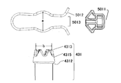
- FIG. 9 is an exploded view of the rotating body holding device 50 according to the second embodiment.
- the rotating body holding device case 502 is located on the most grease filter (rotating body) 301 side.
- a Rotating body attachment / detachment mechanism The rotating body attachment / detachment mechanism 501 is held by sandwiching the boss cylinder 431 (not shown) with a boss cylinder holding member (bar spring having a clamping action) 5012, which will be described in detail later.
- the rotating body attachment / detachment mechanism operation unit 5011 of the rotating body holding device is pushed into the opening 5013 of the boss cylinder holding member so as to cut into the boss cylinder holding member (bar spring having a clamping action) 5012. Opens, and the holding of the boss cylinder 431 is released.
- the boss cylinder 431 is a member protruding above the attachment / detachment device 40, and is a portion straddling the region indicated by the alternate long and short dash line in the front view of the boss member 43 in FIG. 6 (B).
- FIG. 10A shows an enlarged view of the boss cylinder 431 according to the second embodiment.
- FIG. 10B is a perspective view showing a holding relationship between the boss cylinder 431 and the rotating body attachment / detachment mechanism 501 according to the second embodiment.
- a boss cylinder enlarged diameter portion 4315 is formed on the boss cylinder tip portion 4313 side of the boss cylinder 431, and a drive pin receiving groove 4311 is provided.
- a tapered surface 4312 is provided directly below the boss cylinder enlarged diameter portion 4315.
- boss cylinder holding member (bar spring having a clamping action) 5012 sandwiches the tapered surface 4312
- the urging force for sandwiching the boss cylinder holding member (bar spring having a clamping action) generates a component force on the tapered surface 4312 in the direction shown by the arrow in FIG. 10 (B).
- the boss cylinder 431 of the attachment / detachment device 40 is lifted, and the grease filter (rotating body) 301 sandwiched between the boss cylinder 431 and the rotating body holding device 50 acts as an urging portion for pressing the rotating body holding device 50.
- the grease filter (rotating body) 301 does not rattle, and noise and abnormal noise during rotation can be suppressed.
- the angle ⁇ of the tapered surface (see FIG. 10 (A)) suitable for performing the second function is 95 ° to 135 °.
- FIG. 11 is a conceptual diagram showing the relationship between the boss cylinder holding member (bar spring having a clamping action) 5012 and the boss cylinder tip portion 4313 according to the second embodiment.
- the support member 503 shown in FIG. 9 holds a boss cylinder holding member (bar spring having a clamping action) 5012 constituting the rotating body attaching / detaching mechanism 501 and a rotating body attaching / detaching mechanism operating unit 5011 of the rotating body holding device. It is a member that holds and holds the rotating body holding device case 502 so as not to come off.
- the rotating body holding device 50 is mounted by inserting the boss cylinder 431 of the attachment / detachment device 40 to which the grease filter (rotating body) 301 is attached from the boss cylinder inserting hole 5021 of the case of the rotating body holding device 50 shown in FIG. Ru.
- the boss cylinder tip 4313 When the boss cylinder tip 4313 is inserted through the boss cylinder insertion hole 5021 of the case, it first comes into contact with the boss cylinder holding member (bar spring having a clamping action) 5012. Next, when the boss cylinder tip portion 4313 is further pushed in, the boss cylinder tip portion 4313 passes through the boss cylinder insertion hole 5031 of the support member and slightly exits from the rotating body holding device 50 from the boss cylinder insertion hole 5041 of the upper cover. This state is as illustrated in FIG. 5 (B).
- the boss cylinder holding member (bar spring having a clamping action) 5012 is a bar spring having a circular cross section.
- the boss cylinder holding member (bar spring having a clamping action) 5012 is a bar spring having a circular cross section.
- the boss cylinder holding member (bar spring having a clamping action) 5012 has a circular cross section, and the circular boss cylinder holding member (bar spring having a clamping action) 5012 hits the curved surface of the tip portion 4313 of the boss cylinder and holds the rotating body as it is. By continuing to insert the boss cylinder 431 into the device 50, it is expanded and comes into contact with the boss cylinder enlarged diameter portion 4315.
- the rotating body attachment / detachment mechanism 501 has both the first function and the second function, but the rotating body attachment / detachment mechanism 501 originally has the first function. It is sufficient, and it is not necessary to have the second function at the same time. Further, a function (second function) as an urging portion for pressing the grease filter (rotating body) 301 may be provided by an urging portion provided separately from the rotating body attachment / detachment mechanism 501.
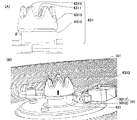
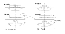
- FIG. 12 is a conceptual diagram showing various aspects of the urging unit according to the second embodiment.
- FIG. 12A is a cushion type. A cushion is provided on the lower surface of the rotating body pressing device 50, and when the rotating body pressing device 50 is attached, it functions as an urging portion for pressing the grease filter (rotating body) 301.
- FIG. 12B is a lever type, and a lever lifting protrusion is provided on the upper surface of the attachment / detachment device 40 to lift the power point of the lever provided on the rotating body holding device 50.
- the point of action on the opposite side of the fulcrum from the point of effort functions as an urging portion that presses the grease filter (rotating body) 301.
- the mode of the urging portion as described above is an example, and may be any one that functions as an urging portion, such as urging by a magnetic force using a magnet, and is limited to the above example. It's not a thing.
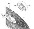
- FIG. 13 is an exploded view showing the mounting relationship of the attachment / detachment device 40, the grease filter (rotating body) 301, and the rotating body holding device 50 according to the second embodiment.
- the boss cylinder 431 protrudes from the attachment / detachment device insertion hole 3015 of the grease filter (rotating body) 301, and the protrusion (engaged) of the attachment / detachment device 40 comes out from the protrusion insertion hole (engagement mechanism) 3016 of the grease filter (rotary body) 301.
- Mechanism) 434 is popping out.
- An annular groove 505 that accommodates the protruding protrusion (engaged mechanism) 434 is provided on the surface of the rotating body holding device 50 on the grease filter (rotating body) 301 side.
- the annular groove 505 has an advantageous effect in that the protrusion (engaged mechanism) 434 can be accommodated regardless of the direction. However, if it is desired to firmly prevent the grease filter (rotating body) 301 from rotating, the rotating body holding device 50 may be provided with a recess in which the protrusion (engaged mechanism) 434 fits.
- the protrusion (engaged mechanism) 434 may be provided on the rotating body holding device 50, and in this case, the annular groove is formed on the mounting surface of the grease filter (rotating body) 301 of the attachment / detachment device 40. It will be provided.
- the protrusions (engaged mechanism) 434 provided on the attachment / detachment device 40 may be arranged with regularity such as arrangement on the same circumference, but may be arranged without regularity. In that case, when the grease filter (rotating body) 301 is attached to the attachment / detachment device 40, it is accommodated in correspondence with the arrangement of the protrusion (engaged mechanism) 434 protruding from the protrusion insertion hole (engagement mechanism) 3016.
- the arrangement of the annular groove 505 and the like on the bottom surface of the rotating body holding device 50 is determined. Further, the grease filter (rotating body) 301 may be provided with an engaging mechanism composed of protrusions, and the attachment / detachment device 40 and / or the rotating body holding device 50 may be provided with an annular groove for accommodating the protrusions or a recess for just accommodating the protrusions. As described above, various aspects are included in the present invention.
- the third embodiment is another aspect of the rotating body holding device 50 of the second embodiment.
- FIG. 14 is a perspective view of the rotating body holding device 50 according to the third embodiment, in which (A) a perspective view and (B) an upper cover 504 are removed.
- the rotating body attachment / detachment mechanism 501 of the third embodiment is similar to the structure of the power shaft attachment / detachment mechanism described in “1 attachment / detachment device A power shaft attachment / detachment mechanism” of the second embodiment. From the side of the rotating body holding device 50 according to the third embodiment illustrated in FIG. 14A, the rotating body attaching / detaching mechanism operation unit 5011 of the rotating body holding device protrudes, and the upper portion is covered with the upper cover 504.
- a boss cylinder insertion hole 5041 for the upper cover is provided in the central portion.
- the rotating body attachment / detachment mechanism 501 is the boss cylinder holding lever 506 of the rotating body holding device provided with the operation unit 5011 of the rotating body attachment / detachment mechanism. , It is composed of a lever spring 5062.
- the rotating body holding device 50 is provided with boss cylinder holding levers 506 of the two rotating body holding devices, and the boss cylinder holding levers 506 of the two rotating body holding devices are respectively provided with lever springs 5062. There is.
- the boss cylinder holding lever 506 of the two rotating body holding devices is urged as shown by an arrow, and the boss cylinder 431 (not shown) inserted into the boss cylinder insertion hole 5061 of the boss cylinder holding lever is inserted. Hold from both sides.
- the pinching position of the boss cylinder holding lever 506 of the two rotating body holding devices is a portion directly below the boss cylinder enlarged diameter portion 4315 shown in FIG. 10 (A), and the boss cylinder 431 is sandwiched at this position. , The attachment / detachment device 40 will not come off.
- the boss cylinder holding lever 506 of the rotating body holding device is held at the position of the tapered surface 4312 in FIG. 10 (A), and an urging force is applied in the direction indicated by the arrow in FIG. 10 (B) to hold the rotating body.
- the boss cylinder 431 is not provided with the tapered surface 4312, and the rotating body is separately pressed as described in "2 Rotating body holding device B Bending part for pressing the rotating body".
- An urging unit may be provided.
- an embodiment in which an urging portion for pressing the rotating body is not provided may be included.
- the fourth embodiment is another aspect of the rotating body holding device 50 of the second embodiment.
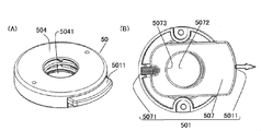
- FIG. 15 shows a perspective view (A) and a perspective view (B) of the rotating body holding device 50 according to the fourth embodiment with the upper cover 504 removed.
- the rotating body attaching / detaching mechanism operation unit 5011 of the rotating body pressing device protrudes from the rotating body pressing device 50.
- the rotating body attachment / detachment mechanism operation unit 5011 of the rotating body pressing device is configured to protrude from the side surface, but any portion that can be operated may be used, and in the present invention, the rotating body pressing device may be used. It may protrude from the top of the device 50.
- the rotating body attachment / detachment mechanism operation unit 5011 of the rotating body holding device can be operated, it is not necessary to pop out.
- other operation units such as the power shaft attachment / detachment mechanism operation unit of the mounting device.
- the rotating body attachment / detachment mechanism 501 is composed of a boss cylinder holding lever 507 provided with a rotating body attaching / detaching mechanism operation unit 5011 of the rotating body holding device and a pressing spring 5071 of the boss cylinder holding lever.
- the boss cylinder holding lever 507 is provided with a rotating body attachment / detachment mechanism operation unit 5011 of the rotating body holding device at one end, and a pressing spring 5071 of the boss cylinder holding lever is attached to the other end.
- the boss cylinder holding lever 507 is urged in the direction of the above, and at a position directly below the boss cylinder expanding portion 4315 (see FIG.
- the boss cylinder contact portion 5073 of the boss cylinder holding lever is the boss of the boss cylinder holding lever.
- the boss cylinder 431 inserted in the cylinder insertion hole 5072 is pressed.
- the boss cylinder 431 is held.
- the boss cylinder insertion hole 5072 of the boss cylinder holding lever is not a perfect circle but has a long diameter in the moving direction of the boss cylinder holding lever 507. If it is a perfect circle, the boss cylinder 431 can be pulled out only when the positions of the boss cylinder enlarged diameter portion 4315 and the boss cylinder insertion hole 5072 of the boss cylinder holding lever match, so the rotating body attachment / detachment mechanism operation unit 5011 of the rotating body holding device It becomes difficult to adjust the amount of movement.
- the rotating body holding device 50 can be removed from the attachment / detachment device 40 without strictly adjusting the pushing degree, and the grease filter (rotating body) 301 can be removed.
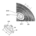
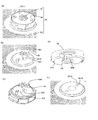
- 16A and 16B are a perspective view of (A) the rotating body mounting device 30 according to the fifth embodiment, (B) a perspective view with the rotating body holding device 50 removed, (C) a perspective view of the attachment / detachment device 40, and (D) a rotating body. It is a perspective view of the holding device 50 seen from the side of the grease filter (rotating body) 301, and (E) an enlarged perspective view of the grease filter (rotating body) 301. In FIG. 16A, the tip end portion 4313 of the boss cylinder of the attachment / detachment device 40 is visible.
- the rotating body mounting device 30 including the attachment / detachment device 40, the grease filter (rotating body) 301, and the rotating body holding device 50 is shown.
- FIG. 16B shows a state in which the rotating body holding device 50 is removed from the state shown in FIG. 16A.
- the grease filter (rotating body) 301 is provided with an engagement protrusion insertion hole (engagement mechanism) 3018 (FIG. 16 (E)), and is provided in the attachment / detachment device 40 as shown in FIG. 16 (B).
- a protrusion (engaged mechanism) 435 is inserted.
- the engaging projection (engaged mechanism) 435 has a shape in which the tip is bent toward the center of the grease filter (rotating body) 301 from the root.
- the engagement projection 435 is inserted into the engagement projection insertion portion 509 of the rotating body pressing device 50 shown in FIG. 16 (D), and then the rotating body pressing device 50 is rotated toward the engagement projection engagement portion 508 side to engage the engaging projection 435. , It is even more firmly stopped.
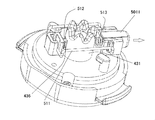
- FIG. 17 is a perspective view of the rotating body attaching / detaching mechanism 501 of the rotating body pressing device 50 according to the fifth embodiment, and is a grease filter (rotation) that must be originally mounted in this state.
- Body 301 is not shown for illustration.
- members unnecessary for explanation are omitted from the rotating body holding device 50 so that the inside of the rotating body holding device 50 can be seen.
- the shape of the boss cylinder 431 of the fifth embodiment is different from that of the second to fourth embodiments, and is cylindrical without the boss cylinder enlarged diameter portion 4315. Further, the boss cylinder 431 is provided with a fitting groove 436 on the side surface. The shape of the fitting groove 436 is shown in FIG.
- the attachment / detachment protrusion 512 is connected to the rotating body attachment / detachment mechanism operation unit 5011 of the rotating body holding device by the link mechanism 511.
- the rotating body attachment / detachment mechanism operation unit 5011 of the rotating body holding device is provided with a attachment / detachment protrusion urging spring 513 that urges the rotor in the direction of the arrow in the drawing.
- Example 2 Biasing part for pressing the rotating body
- the boss cylinder holding member (bar spring having a clamping action) 5012 sandwiches the tapered surface 4312, so that the urging force for sandwiching the boss cylinder holding member (bar spring) 5012.
- a component force is generated on the tapered surface 4312, and the urging portion is configured so as to sandwich the grease filter (rotating body) 301 with the attachment / detachment device 40 in the direction shown by the arrow.
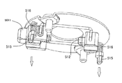
- Example 5 unlike that, an urging portion for pressing the grease filter (rotating body) 301 was configured by providing the backlash prevention protrusion 515.
- the backlash prevention protrusion 515 is provided on the surface of the rotating body holding device 50 on the grease filter (rotating body) 301 side.
- FIG. 18 is a perspective view of a state in which a member unnecessary for the explanation of the rotating body holding device 50 according to the fifth embodiment is removed, and the backlash prevention protrusion 515 is arranged via the backlash prevention protrusion urging spring 516 and the arrow indicates. Being urged in the direction.
- the backlash prevention protrusion 515 functions as an urging portion that presses the grease filter (rotating body) 301.
- the grease filter (rotating body) 301 sandwiched between the attachment / detachment device 40 and the rotating body holding device 50 is prevented from rattling.
- the rotating body has been described as a grease filter (rotating body) 301, but it may be used for a fan used in a range hood. Further, the present invention is a general-purpose technique that can be used in a rotating body other than a range hood.
- the rotating body mounting device including the rotating body and the mounting device can be integrally attached to and detached from the power shaft, and especially when the rotating body is located at a high place such as a range hood, the removal work can be performed. Installation work has become easier. Further, since the rotating body attachment / detachment mechanism operation unit for attaching / detaching the rotating body from the rotating body mounting device is provided on the side where the power shaft which is normally out of reach is inserted, the rotating body attachment / detachment mechanism operation unit is mistakenly operated to rotate. It is avoided that the body disassembles and falls.
Landscapes
- Engineering & Computer Science (AREA)
- General Engineering & Computer Science (AREA)
- Mechanical Engineering (AREA)
- Chemical & Material Sciences (AREA)
- Combustion & Propulsion (AREA)
- Structures Of Non-Positive Displacement Pumps (AREA)
- Ventilation (AREA)
- Filtering Of Dispersed Particles In Gases (AREA)
Abstract
本発明は、回転体の取り外し、取り付けの作業性を向上させた回転体装着装置を提供することを目的とする。回転体および取付装置(302)を含む、動力軸(20)に挿入される回転体装着装置(30)であって、前記取付装置(302)は、前記動力軸(20)を挿入する挿入孔を有し、前記動力軸(20)との駆動連結部を有し、前記回転体を基準として、前記取付装置(302)に前記動力軸(20)を挿入しない側に、前記回転体装着装置(30)を前記動力軸(20)と着脱する動力軸着脱機構操作部を有し、前記回転体を基準として、前記取付装置(302)に前記動力軸(20)を挿入する側に、前記回転体を前記回転体装着装置(30)から着脱する回転体着脱機構操作部を有する、回転体装着装置とすることで課題の解決を図った。
Description
本発明は、レンジフード等における回転体装着装置に関する。
レンジフードは、排気を行うためのプロペラファン、シロッコファン、ターボファンなどの回転体や油や埃等を回収するためのグリスフィルタなどの回転体を備えている。これらの回転体をモータで回転させて、排気や排気に含まれる油の回収を図っている。
ファンやグリスフィルタなどの回転体は、調理によって発生した油煙に由来する油等が付着しやすいため、定期的な清掃が必要となる。そのため、汚れた回転体を清掃するためには、定期的に回転体を駆動シャフトから取り外す必要がある。
例えば、特許文献1のものは、スピンナーとよばれるネジの付いた取付けツマミを取り外すことにより、ボス筒と羽根車主体とを分離できるようになっている。しかし、特に羽根車が下向きに取り付けられているときは、スピンナーを外すと、ボス筒、羽根車主体、スピンナーの3部材が一挙にばらばらに外れ、部材が落下してしまいかねなかった。落下を防ぐためには、羽根車主体を片手で支えながら、スピンナーをもう片方の手で外す必要があり、作業性の悪い空間でそのような体勢を作業者に強いるものであった。
さらに、装着時にも、同様に羽根車主体を支えながら、スピンナーを回す必要があり作業性が悪かった。
本発明は、動力軸への取り付け、取り外しの作業性を向上させた回転体装着装置を提供することを目的とする。
本発明の請求項1の態様は、回転体および取付装置302を含む、動力軸20に挿入される回転体装着装置30であって、前記取付装置302は、前記動力軸20を挿入する挿入孔を有し、前記動力軸20との駆動連結部を有し、前記回転体を基準として、前記取付装置302に前記動力軸20を挿入しない側に、前記回転体装着装置を前記動力軸20と着脱する動力軸着脱機構操作部を有し、前記回転体を基準として、前記取付装置302に前記動力軸20を挿入する側に、前記回転体を前記回転体装着装置30から着脱する回転体着脱機構操作部を有する、回転体装着装置30とすることで課題を解決した。
これにより、前記回転体および前記取付装置302を含む回転体装着装置30は、簡単に一体となったまま動力軸20から取り外せるようになった。
また、回転体を基準として、取付装置302に動力軸20を挿入する側に取付装置の回転体着脱機構操作部を設けたことで、回転体装着装置30を動力軸20に装着した状態では、取付装置の回転体着脱機構操作部は回転体の奥に位置し、手が届かない。そのため、回転体装着装置30を前述したように取り外してからでないと、取付装置の回転体着脱機構操作部が操作できないように構成されている。これにより、回転体装着装置30を動力軸20に装着した状態で、誤って取付装置の回転体着脱機構操作部を操作することを防ぐことができるようになった。
また、回転体を基準として、取付装置302に動力軸20を挿入する側に取付装置の回転体着脱機構操作部を設けたことで、回転体装着装置30を動力軸20に装着した状態では、取付装置の回転体着脱機構操作部は回転体の奥に位置し、手が届かない。そのため、回転体装着装置30を前述したように取り外してからでないと、取付装置の回転体着脱機構操作部が操作できないように構成されている。これにより、回転体装着装置30を動力軸20に装着した状態で、誤って取付装置の回転体着脱機構操作部を操作することを防ぐことができるようになった。
本発明の請求項2の態様のように、前記取付装置302は、前記動力軸着脱機構操作部を有する着脱装置40と前記回転体着脱機構操作部5011を有する回転体押さえ装置50からなる請求項1記載の回転体装着装置30としてもよい。
取付装置302が着脱装置40と回転体押さえ装置50に分離することにより、回転体の着脱を簡単にすることができる。
取付装置302が着脱装置40と回転体押さえ装置50に分離することにより、回転体の着脱を簡単にすることができる。
本発明の請求項3の態様のように、前記着脱装置40は、前記回転体に挿入するボス筒431を備え、前記回転体押さえ装置50の前記回転体着脱機構操作部5011は、前記ボス筒431を保持および解除するように設けられていることを特徴とする請求項2記載の回転体装着装置30としてもよい。
これにより、回転体着脱機構操作部5011の一度の操作で、回転体装着装置30を着脱装置40、回転体、回転体押さえ装置50の3つの部材に分解することができるようになる。また、回転体装着装置30を動力軸20に装着した状態で、誤って着脱装置40と回転体押さえ装置50が分離することを防ぐことができる。
これにより、回転体着脱機構操作部5011の一度の操作で、回転体装着装置30を着脱装置40、回転体、回転体押さえ装置50の3つの部材に分解することができるようになる。また、回転体装着装置30を動力軸20に装着した状態で、誤って着脱装置40と回転体押さえ装置50が分離することを防ぐことができる。
本発明の請求項4の態様のように、前記着脱装置40および/または前記回転体押さえ装置50は、前記回転体を押さえつける付勢部を有することを特徴とする請求項2または3記載の回転体装着装置30としてもよい。
これにより、回転体と回転体押さえ装置50および/または回転体と着脱装置40の間のガタがなくなり騒音等が起きないようになった。
これにより、回転体と回転体押さえ装置50および/または回転体と着脱装置40の間のガタがなくなり騒音等が起きないようになった。
本発明の請求項5の態様のように、前記着脱装置40には、前記回転体側に向けて縮径するテーパー面4312が設けられ、前記回転体押さえ装置50の前記付勢部は、前記テーパー面4312を挟む付勢部材により構成され、前記付勢部材を開く操作部5011を設けることで、回転体着脱機構501としても機能するように構成した請求項4記載の回転体装着装置30としてもよい。
これにより、回転体押さえ装置50の前記付勢部は、ボス筒431の保持および解除と回転体を押さえつける2つの機能を併せ持つことができる。
これにより、回転体押さえ装置50の前記付勢部は、ボス筒431の保持および解除と回転体を押さえつける2つの機能を併せ持つことができる。
本発明の請求項6の態様のように、前記回転体は、前記着脱装置および/または前記回転体押さえ装置との装着面に、凹部および/または凸部を有し、これにはまり込むように前記着脱装置40および/または前記回転体押さえ装置50に、凸部および/または凹部が備えられていることを特徴とする、請求項2~5記載のいずれか1項記載の回転体装着装置30としてもよい。
例えば回転体がグリスフィルタ(回転体)301である場合に、表面と裏面があり、また、回転体がシロッコファンのような場合には上面と下面がある。着脱装置40および回転体押さえ装置50に対して、正しい面で回転体が装着されないと、回転体が正しく機能しないことがある。
そのようなケースにおいては、前記回転体は、前記着脱装置40に設けられた回転体側凸部または凹部とはまり込む着脱装置側凹部または凸部を有することで、誤って表裏逆にまたは上下逆に回転体を取り付けてしまうことを防止できる。
そのようなケースにおいては、前記回転体は、前記着脱装置40に設けられた回転体側凸部または凹部とはまり込む着脱装置側凹部または凸部を有することで、誤って表裏逆にまたは上下逆に回転体を取り付けてしまうことを防止できる。
また、別の態様として前記回転体押さえ装置は、前記回転体に設けられた回転体押さえ装置側凹部または凸部とはまり込む、回転体側凸部または凹部が設けられていてもよい。
回転体の凹部および/または凸部は、前記装着面を湾曲させて、例えば、着脱装置40側に凸部となるような湾曲(回転体押さえ装置50側から見れば凹部となるような湾曲)でもよいし、前記装着面の着脱装置40側のみ、または、回転体押さえ装置50側のみに凹部や凸部を設けてもよい。もちろん、着脱装置40側と回転体押さえ装置50側にそれぞれ凹部や凸部を設けてもよい。いずれにせよ、回転体の前記装着面に設けた凹部および/または凸部にはまり込むように、着脱装置40および/または回転体押さえ装置50に凹部/または凸部が設けられればよい。また、凹部や凸部の形状は様々であり得る。
回転体の凹部および/または凸部は、前記装着面を湾曲させて、例えば、着脱装置40側に凸部となるような湾曲(回転体押さえ装置50側から見れば凹部となるような湾曲)でもよいし、前記装着面の着脱装置40側のみ、または、回転体押さえ装置50側のみに凹部や凸部を設けてもよい。もちろん、着脱装置40側と回転体押さえ装置50側にそれぞれ凹部や凸部を設けてもよい。いずれにせよ、回転体の前記装着面に設けた凹部および/または凸部にはまり込むように、着脱装置40および/または回転体押さえ装置50に凹部/または凸部が設けられればよい。また、凹部や凸部の形状は様々であり得る。
本発明の請求項7の態様のように、前記回転体は、少なくとも1つの係合機構(3016、3018)を有し、前記着脱装置40または前記回転体押さえ装置50には、前記係合機構(3016、3018)と係合する被係合機構(434、435)を有する請求項2~6のいずれか1項記載の回転体装着装置30としてもよい。
これにより、回転体を確実に回り止めすることができるようになった。
これにより、回転体を確実に回り止めすることができるようになった。
本発明の請求項8の態様のように、前記態様の回転体装着装置30と、前記回転体装着装置30を回転させる動力装置4と、油を捕集する油分捕集部材5を備える油捕集装置としてもよい。
これにより、油分捕集部材5を加えることで、油の付着しやすい環境下でも回転体装着装置30を使用しやすくなった。
これにより、油分捕集部材5を加えることで、油の付着しやすい環境下でも回転体装着装置30を使用しやすくなった。
本発明の請求項9の態様のように、前記態様の回転体装着装置30または油捕集装置を備えた、レンジフード1としてもよい。
本発明に含まれる回転体装着装置や油捕集装置は、様々な回転体に使用できるものであるが、中でも、レンジフード1で使用されている回転体には、グリスフィルタやファンなどがあり、これらにも活用できることを明らかにした。
本発明に含まれる回転体装着装置や油捕集装置は、様々な回転体に使用できるものであるが、中でも、レンジフード1で使用されている回転体には、グリスフィルタやファンなどがあり、これらにも活用できることを明らかにした。
本発明によれば、回転体および取付装置からなる回転体装着装置が一体となった状態で動力軸へ取り付け、取り外しができるため、作業性が向上する。
<実施例1>
実施例1は、本発明をレンジフード1のグリスフィルタ(回転体)301に適用した実施例である。図1は、整流板を取り外したレンジフード1の底面側からの斜視図であり、レンジフード1の下面を覆う整流板を取り外した状態を図示している。回転体に相当するグリスフィルタ(回転体)301が取付装置302により装着されている。
グリスフィルタ(回転体)301の周囲には油分捕集部材としても機能するベルマウス(油分捕集部材)5が装着されている。
実施例1は、本発明をレンジフード1のグリスフィルタ(回転体)301に適用した実施例である。図1は、整流板を取り外したレンジフード1の底面側からの斜視図であり、レンジフード1の下面を覆う整流板を取り外した状態を図示している。回転体に相当するグリスフィルタ(回転体)301が取付装置302により装着されている。
グリスフィルタ(回転体)301の周囲には油分捕集部材としても機能するベルマウス(油分捕集部材)5が装着されている。
回転体装着装置30は、グリスフィルタ(回転体)301と取付装置302の少なくとも2つの部材から構成されている。取付装置302は、グリスフィルタ(回転体)301を挟んで両側に位置する部材であり、底面側からの斜視図である図1では、取付装置302の下側が見えている。取付装置302の両側から取付装置の動力軸着脱機構操作部303が突出している。
取付装置の動力軸着脱機構操作部303を押圧すると、回転体装着装置30内に挿入されている動力軸(図示されていない)から回転体装着装置30が外れる。具体的な構造は後述する実施例2の「1 着脱装置 A 動力軸着脱機構」と同様である。
グリスフィルタ(回転体)301と取付装置302とで構成される回転体装着装置30が一体となったまま動力軸20から外せるため、取付装置302を作業者が保持していれば、グリスフィルタ(回転体)301を特段支えなくともグリスフィルタ(回転体)301が外れて落ちてくることはない。
グリスフィルタ(回転体)301と取付装置302とで構成される回転体装着装置30が一体となったまま動力軸20から外せるため、取付装置302を作業者が保持していれば、グリスフィルタ(回転体)301を特段支えなくともグリスフィルタ(回転体)301が外れて落ちてくることはない。
図2は、送風機ボックスの一部を説明のために取り除いたレンジフード1の上側からの斜視図 である。当該送風機ボックス内には、ファンケーシング6が設けられており、その内部にはファンとファンを駆動するモータが収められている。グリスフィルタ(回転体)301を駆動するグリスフィルタ駆動モータ(動力装置)4は、グリスフィルタ駆動モータ桟7上に固定されている。
図3は、実施例1に係る(A)グリスフィルタ駆動モータ(動力装置)4の斜視図、(B)グリスフィルタ(回転体)301及び取付装置302をグリスフィルタ駆動モータ(動力装置)4側から見た斜視図および(C)図3(B)の一点鎖線円内を拡大した斜視図である。
図3(A)に記載のグリスフィルタ駆動モータ(動力装置)4の動力軸20は、図3(B)および(C)に描かれた動力軸挿入孔305に挿入される。そして、動力軸20に設けられている一対の駆動ピン201が動力軸挿入孔305の入り口付近に設けられた駆動ピン受入溝306に嵌合する。駆動ピン受入溝306は、複数対設けられており、動力軸20がどのような周方向で動力軸挿入孔305に入れられても、嵌合できるように構成されている。
図3(B)に示されているように、取付装置302からは、取付装置の回転体着脱機構操作部3071が一対設けられており、また、一対の回転体押圧ストッパー3072がグリスフィルタ(回転体)301の上面に飛び出ている。また、グリスフィルタ(回転体)301の周囲にはベルマウス(油分捕集部材)5が配置されており、後述するように油分捕集部材として機能する。
図4は、実施例1に係る回転体装着装置30の(A)正面図、(B)断面図、(C)回転体取り外し時の、回転体押圧ストッパー3072の位置を示す断面図とグリスフィルタ(回転体)301の取付装置挿入孔3011との位置関係を示す概念図を示す。
回転体装着装置30は、図4(A)~(C)のように、グリスフィルタ(回転体)301と取付装置302の2つの構成部材の組立体である。
回転体着脱機構307は、取付装置の回転体着脱機構操作部3071と回転体押圧ストッパー3072とで構成され、清掃等のため、回転体装着装置30の構成部材であるグリスフィルタ(回転体)301を取付装置302から取り外すときには取付装置の回転体着脱機構操作部3071を押圧する。
回転体装着装置30は、図4(A)~(C)のように、グリスフィルタ(回転体)301と取付装置302の2つの構成部材の組立体である。
回転体着脱機構307は、取付装置の回転体着脱機構操作部3071と回転体押圧ストッパー3072とで構成され、清掃等のため、回転体装着装置30の構成部材であるグリスフィルタ(回転体)301を取付装置302から取り外すときには取付装置の回転体着脱機構操作部3071を押圧する。
取付装置の回転体着脱機構操作部3071を押圧する前の状態を示す図4(B)の状態において、取付装置の回転体着脱機構操作部3071を押圧すると、図4(C)のように回転体押圧ストッパー3072が取付装置302内に移動し、取付装置302内に完全に収まるように構成されている。回転体押圧ストッパー3072の移動機構については図示されていないが、取付装置の回転体着脱機構操作部3071と回転体押圧ストッパー3072がリンク機構により連結されているものや、取付装置の回転体着脱機構操作部3071の操作に基づき作動する電磁リレーを設けて回転体押圧ストッパー3072が移動するものなど移動機構の種類は問わない。
取付装置の回転体着脱機構操作部3071の操作により回転体押圧ストッパー3072が取付装置302内に完全に収まった状態になると、図4(C)のように、グリスフィルタ(回転体)301の中央に設けられた取付装置挿入孔3011から取付装置302が抜ける状態となる。
グリスフィルタ(回転体)301の取付装置302への取り付けは、この逆を行えばよい。
グリスフィルタ(回転体)301の取付装置302への取り付けは、この逆を行えばよい。
取付装置302には、動力軸20が、図4(A)の動力軸挿入孔305側から挿入され、取付装置302は、グリスフィルタ(回転体)301を基準として、取付装置302に動力軸20を挿入しない側に、取付装置302を動力軸20と着脱する取付装置の動力軸着脱機構操作部303が設けられていることが分かる。
このような位置に取付装置の動力軸着脱機構操作部303があると、図1のように、レンジフード1の下側から簡単に手が届くようになる。
動力軸20が水平に設けられているレンジフード1であっても、簡単に取付装置の動力軸着脱機構操作部303に手が届く。
このような位置に取付装置の動力軸着脱機構操作部303があると、図1のように、レンジフード1の下側から簡単に手が届くようになる。
動力軸20が水平に設けられているレンジフード1であっても、簡単に取付装置の動力軸着脱機構操作部303に手が届く。
また、取付装置302は、グリスフィルタ(回転体)301を基準として、取付装置302に動力軸20を挿入する側に、取付装置の回転体着脱機構操作部3071を有している。
このような位置に、取付装置の回転体着脱機構操作部3071があると、回転体装着装置30を動力軸20から取り外した後でないと、グリスフィルタ(回転体)301を取付装置302から取り外せない。図1からも分かるように、取付装置の回転体着脱機構操作部3071は、レンジフード1の下から見えず手が届かない位置にあり、作業者が誤って取付装置の回転体着脱機構操作部3071を操作することができないようになっている。
グリスフィルタ(回転体)301を取付装置302から取り外せるようにしたのは、取り外すことでグリスフィルタ(回転体)301を清掃しやすくするためである。また、汚れたときに使い捨てタイプのグリスフィルタ(回転体)301を使用するときには、取付装置の回転体着脱機構操作部3071があるので、簡単に交換することができる。
実施例1においては、回転体をグリスフィルタ(回転体)301として説明したが、レンジフード1に使用されるファンに用いてもよい。また、本発明は、レンジフード以外の回転体においても使用できる汎用的な技術である。以下の実施例においても同様である。
(油捕集装置)
図1および図3(B)に図示されたベルマウス(油分捕集部材)5は、グリスフィルタ(回転体)301から遠心力で飛ぶ油を捕集できるように、円環状の溝部を有しており油分捕集部材としても機能する。溜まった油は、ベルマウス(油分捕集部材)5を外すだけで、簡単に廃棄することができる。
回転体が、ファンの場合も、ファンから遠心力で飛ぶ油を捕集する油分捕集部材を設けてもよい。また、ファンのケーシング等から垂れてくる油を捕集する油分捕集部材を設けてもよい。
どの部材から油が垂れるか、そして、油が垂れてくる位置等により油分捕集部材の形状や設置位置は適宜変更可能である。
油分捕集部材は、ベルマウス(油分捕集部材)5に限らず、様々なものが本発明に包含される。また、油を排出する排出管を油分捕集部材に設けてもよい。
いずれにせよ、油が回転体に付着する環境下では、油分捕集部材を設けることで、油の処理を簡単に行うことができる。
<実施例2>
実施例2は、レンジフード1に使用されるグリスフィルタ(回転体)301を回転体とした実施の態様である。実施例1と異なるのは、取付装置302が、着脱装置40と回転体押さえ装置50にさらに分離できるようになっていることである。
図5には、実施例2に係る(A)グリスフィルタ駆動モータ(動力装置)4の正面図、(B)回転体装着装置30の正面図、(C)回転体装着装置30の回転体押さえ装置50を外した分解正面図、(D)回転体装着装置30の回転体押さえ装置50およびグリスフィルタ(回転体)301を外した分解正面図が示されている。
実施例2は、レンジフード1に使用されるグリスフィルタ(回転体)301を回転体とした実施の態様である。実施例1と異なるのは、取付装置302が、着脱装置40と回転体押さえ装置50にさらに分離できるようになっていることである。
図5には、実施例2に係る(A)グリスフィルタ駆動モータ(動力装置)4の正面図、(B)回転体装着装置30の正面図、(C)回転体装着装置30の回転体押さえ装置50を外した分解正面図、(D)回転体装着装置30の回転体押さえ装置50およびグリスフィルタ(回転体)301を外した分解正面図が示されている。
図5(A)には、後述する「1 着脱装置 A 動力軸着脱機構」で説明するように、動力軸着脱機構の構成部材である第1および第2動力軸保持レバー(403、404)によって保持される動力軸20の縮径部202が示されている。
動力軸20は、図5(B)のボス筒動力軸挿入孔433から挿入され、動力軸20に回転体装着装置30が装着される。
動力軸20は、図5(B)のボス筒動力軸挿入孔433から挿入され、動力軸20に回転体装着装置30が装着される。
図5(B)には、動力軸20は示していないが、図5(B)の着脱装置の動力軸着脱機構操作部401を操作することで、回転体装着装置30(回転体押さえ装置50、グリスフィルタ(回転体)301および着脱装置40の3つの部材で構成される)が一体となって、動力軸20から取り外せるようになっている。
図5(C)のように回転体装着装置30を動力軸20から取り外した後、回転体押さえ装置の回転体着脱機構操作部5011を操作することで、グリスフィルタ(回転体)301を押さえていた回転体押さえ装置50が外れ、グリスフィルタ(回転体)301が取り外せる状態となる。
図5(D)のように最後に、グリスフィルタ(回転体)301を着脱装置40から取り外すと、回転体装着装置30を構成する3つの部材がすべてバラバラになる。
図5(B)からも分かるように、グリスフィルタ(回転体)301を基準として、回転体装着装置30に動力軸20を挿入する側に回転体押さえ装置の回転体着脱機構操作部5011が設けられており、これを操作することでグリスフィルタ(回転体)301を回転体装着装置30から着脱することができるようになっている。
レンジフード1において、回転体装着装置30が取り付けられた状態では、グリスフィルタ(回転体)301が邪魔になり、回転体押さえ装置の回転体着脱機構操作部5011を操作することができないことは、実施例1と同様である。
着脱装置の動力軸着脱機構操作部401は、着脱装置40に設けられており、これを操作すると、回転体装着装置30全体が動力軸20から離脱し、グリスフィルタ(回転体)301、着脱装置40および回転体押さえ装置50の3つの部材が一体となって取り外せる。
図5(B)の回転体装着装置30は、レンジフード1から整流板を取り外すだけで、着脱装置の動力軸着脱機構操作部401が、作業者から見える位置になるように配置されており、簡単に操作できるように構成されている。
次いで、回転体装着装置30の構造と機能を説明する。
1 着脱装置
A 動力軸着脱機構
図6は、実施例2に係る着脱装置40の(A)分解図、(B)ボス部材43正面図である。着脱装置40には、第1動力軸保持レバー403、第2動力軸保持レバー404および動力軸保持レバー付勢部材402で構成される動力軸着脱機構が収められている。そして、第1動力軸保持レバー403および第2動力軸保持レバー404は、それぞれ着脱装置の動力軸着脱機構操作部401、保持レバー動力軸挿入孔405および動力軸当接保持部407を備えている。
図6(A)を参照されたい。着脱装置下カバー41内には、サポートカバー42が収められている。サポートカバー42の上に第1動力軸保持レバー403および第2動力軸保持レバー404が摺動自在に設けられている。
第1動力軸保持レバー403および第2動力軸保持レバー404には、付勢部材当接部406が設けられており、動力軸保持レバー付勢部材402の一端が当接するようになっている。動力軸保持レバー付勢部材402の他端はボス部材43に当接している(図7参照)。
動力軸保持レバー付勢部材402は、第1および第2動力軸保持レバー(403、404)を図6中の矢印の方向に付勢しており、着脱装置の動力軸着脱機構操作部401が、ボス部材43外に出るように付勢されている。
図7は、実施例2に係る動力軸20と第1動力軸保持レバー403との当接関係を示すボス部材下面斜視図であり、第1動力軸保持レバー403が、動力軸20の縮径部202を保持する様子が図示されている。説明のため、第2動力軸保持レバー404は、図示していない。第1および第2動力軸保持レバー(403、404)は、動力軸保持レバー付勢部材402により、動力軸20の縮径部202を保持している。動力軸20の縮径部202の形状は、図5(A)を参照されたい。
図7は、実施例2に係る動力軸20と第1動力軸保持レバー403との当接関係を示すボス部材下面斜視図であり、第1動力軸保持レバー403が、動力軸20の縮径部202を保持する様子が図示されている。説明のため、第2動力軸保持レバー404は、図示していない。第1および第2動力軸保持レバー(403、404)は、動力軸保持レバー付勢部材402により、動力軸20の縮径部202を保持している。動力軸20の縮径部202の形状は、図5(A)を参照されたい。
前述したように、第1動力軸保持レバー403は、図示された矢印の方向へ動力軸保持レバー付勢部材402(第1動力軸保持レバー403の背面に隠れて、図示されていない)により付勢されており、動力軸当接保持部407が動力軸20の縮径部202に当接し、保持していることが分かる。第2動力軸保持レバー404も同様である。
動力軸20に回転体装着装置30を取り付けた際には、動力軸20の縮径部202が、第1および第2動力軸保持レバー(403、404)により両側から保持されることになる。
動力軸保持レバー付勢部材402の一例としてコイルバネが挙げられるが、同等の機能を有するものであれば、板バネ、ゴム等の弾性体等いかなるものでもよい。
動力軸20に回転体装着装置30を取り付けた際には、動力軸20の縮径部202が、第1および第2動力軸保持レバー(403、404)により両側から保持されることになる。
動力軸保持レバー付勢部材402の一例としてコイルバネが挙げられるが、同等の機能を有するものであれば、板バネ、ゴム等の弾性体等いかなるものでもよい。
再び図6に戻ると、動力軸20は、ボス部材43のボス筒動力軸挿入孔433に挿入され、次いで第1および第2動力軸保持レバー(403、404)の保持レバー動力軸挿入孔405、サポートカバー動力軸挿入孔421を通って、着脱装置下カバー41の中央部に設けられた動力軸先端当接部411まで挿入される。このとき、第1および第2動力軸保持レバー(403、404)のある位置に動力軸20の縮径部202がちょうど位置するように設計されている。
回転体装着装置30を動力軸20から取り外す場合は、第1および第2動力軸保持レバー(403、404)の着脱装置の動力軸着脱機構操作部401を、動力軸保持レバー付勢部材402の付勢力に抗して押し込む。すると、動力軸20の縮径部202から 第1および第2動力軸保持レバー(403、404)の動力軸当接保持部407が離れ、回転体装着装置30を動力軸20から抜くことができる。
B 回転体と着脱装置(ボス部材)の係合機構
図8は、実施例2に係る回転体装着装置30の着脱装置40とグリスフィルタ(回転体)301の斜視図である。ボス部材43のグリスフィルタ(回転体)301に面する側に突起(被係合機構)434が図示されている。
図8は、実施例2に係る回転体装着装置30の着脱装置40とグリスフィルタ(回転体)301の斜視図である。ボス部材43のグリスフィルタ(回転体)301に面する側に突起(被係合機構)434が図示されている。
グリスフィルタ(回転体)301には、突起挿入孔(係合機構)3016が設けられており、ボス部材43の上面にある突起(被係合機構)434が挿入されるように構成されている。これにより、グリスフィルタ(回転体)301とボス部材43は、強固に回り止めされる。
回転体の係合機構と着脱装置の被係合機構は、回り止めとして機能すればよく、突起(被係合機構)434の形状や、突起挿入孔(係合機構)3016の形状は様々にできる。また、実施例2においては、図5(D)に示す突起(被係合機構)434は、グリスフィルタ(回転体)301と組み立てられると、図5(C)に示すようにグリスフィルタ(回転体)301の反対面から飛び出るように構成したが、グリスフィルタ(回転体)301と掛け合うだけでもよい。また、突起挿入孔(係合機構)3016に代えて、グリスフィルタ(回転体)301の上面に装着時に突起(被係合機構)434がちょうど収まるキャップ(係合機構)として設けてもよい。このようにしても強固に回り止めされる。
実施例2では、着脱装置40側に突起(被係合機構)434を設けたが、後述する回転体押さえ装置50側に設けてもよいし、着脱装置40と回転体押さえ装置50の双方に突起(被係合機構)を設けてもよい。
また、突起(被係合機構)434をグリスフィルタ(回転体)301に設け、着脱装置40および/または回転体押さえ装置50の側に、グリスフィルタ(回転体)301に設けた突起(被係合機構)434を収める収容部(係合機構)を設けるものとしてもよい。
また、突起(被係合機構)434をグリスフィルタ(回転体)301に設け、着脱装置40および/または回転体押さえ装置50の側に、グリスフィルタ(回転体)301に設けた突起(被係合機構)434を収める収容部(係合機構)を設けるものとしてもよい。
C 回転体裏表逆付け防止機構
図8には、着脱装置の上面にグリスフィルタ取付用凸部44が図示されている。グリスフィルタ(回転体)301には、着脱装置40側からみると凹部となっている着脱装置受入用凹部3017が着脱装置40との装着面に設けられている。
図8に図示されている通り、着脱装置受入用凹部3017の直径Aより、グリスフィルタ取付用凸部44の直径A’は小さく、好ましくは略同径であり、両者がはまり込む。
グリスフィルタ取付用凸部44と着脱装置受入用凹部3017があることで、誤ってグリスフィルタ(回転体)301を裏表逆向きに取り付けてしまうこと防ぐ、グリスフィルタ(回転体)301の裏表逆付け防止機構として機能する。
図8には、着脱装置の上面にグリスフィルタ取付用凸部44が図示されている。グリスフィルタ(回転体)301には、着脱装置40側からみると凹部となっている着脱装置受入用凹部3017が着脱装置40との装着面に設けられている。
図8に図示されている通り、着脱装置受入用凹部3017の直径Aより、グリスフィルタ取付用凸部44の直径A’は小さく、好ましくは略同径であり、両者がはまり込む。
グリスフィルタ取付用凸部44と着脱装置受入用凹部3017があることで、誤ってグリスフィルタ(回転体)301を裏表逆向きに取り付けてしまうこと防ぐ、グリスフィルタ(回転体)301の裏表逆付け防止機構として機能する。
実施例2では、グリスフィルタ(回転体)301に着脱装置受入用凹部3017を設けているが、着脱装置受入用凸部としても実施でき、この場合、着脱装置40には、グリスフィルタ取付凹部が設けられることになる。また、回転体押さえ装置50のグリスフィルタ(回転体)301に向く面に、グリスフィルタ取付用凸部や凹部を設け、これがグリスフィルタ(回転体)301の回転体押さえ装置受入用凹部や凸部とはまり込むようにしても、逆付け防止を達成できる。
また、グリスフィルタ(回転体)301の着脱装置40側と回転体押さえ装置50側の両方に凹部および/または凸部を設けてもよく、前記凹部および/または凸部にはまり込むように、着脱装置40と回転体押さえ装置50に凹部および/または凸部が設けられる。
さらに、グリスフィルタ(回転体)301の凹部および/または凸部にはまり込む、着脱装置40および/または回転体押さえ装置50の凹部および/または凸部は、裏表逆付け防止機構として機能するのであればよく、完全に同径である必要はない。
さらに、グリスフィルタ(回転体)301の凹部および/または凸部にはまり込む、着脱装置40および/または回転体押さえ装置50の凹部および/または凸部は、裏表逆付け防止機構として機能するのであればよく、完全に同径である必要はない。
D 駆動連結部
図6(A)に記載のように、着脱装置40はボス筒動力軸挿入孔433に動力軸20が挿入されるように構成されており、着脱装置40の先端には、駆動ピン受入溝4311が、複数対設けられている。動力軸20がどのような周方向でボス筒動力軸挿入孔433に入れられても、1対の駆動ピン201が、駆動ピン受入溝4311と嵌合できるように構成されている。駆動ピン201と駆動ピン受入溝4311とで駆動連結部が構成される。
図6(A)に記載のように、着脱装置40はボス筒動力軸挿入孔433に動力軸20が挿入されるように構成されており、着脱装置40の先端には、駆動ピン受入溝4311が、複数対設けられている。動力軸20がどのような周方向でボス筒動力軸挿入孔433に入れられても、1対の駆動ピン201が、駆動ピン受入溝4311と嵌合できるように構成されている。駆動ピン201と駆動ピン受入溝4311とで駆動連結部が構成される。
2 回転体押さえ装置
図9は、実施例2に係る回転体押さえ装置50の分解図である。最もグリスフィルタ(回転体)301側に、回転体押さえ装置ケース502が位置している。
図9は、実施例2に係る回転体押さえ装置50の分解図である。最もグリスフィルタ(回転体)301側に、回転体押さえ装置ケース502が位置している。
A 回転体着脱機構
回転体着脱機構501は、詳しくは後述するがボス筒保持部材(クランプ作用のある棒バネ)5012でボス筒431(図示されていない)を挟んで保持している。保持を解除する場合、回転体押さえ装置の回転体着脱機構操作部5011が、ボス筒保持部材開口部5013に割入るように押し込まれることで、ボス筒保持部材(クランプ作用のある棒バネ)5012が開き、ボス筒431の保持が解除される。
回転体着脱機構501は、詳しくは後述するがボス筒保持部材(クランプ作用のある棒バネ)5012でボス筒431(図示されていない)を挟んで保持している。保持を解除する場合、回転体押さえ装置の回転体着脱機構操作部5011が、ボス筒保持部材開口部5013に割入るように押し込まれることで、ボス筒保持部材(クランプ作用のある棒バネ)5012が開き、ボス筒431の保持が解除される。
ボス筒431は、着脱装置40の上方に飛び出た部材であり、図6(B)のボス部材43正面図において一点鎖線で示す領域にまたがっている部位である。図10(A)には実施例2に係るボス筒431の拡大図が示されている。また、図10(B)は実施例2に係るボス筒431と回転体着脱機構501の保持関係を示す斜視図である。
ボス筒431のボス筒先端部4313側には、ボス筒拡径部4315が形成されており、駆動ピン受入溝4311が設けられている。そして、ボス筒拡径部4315の直下に、テーパー面4312が設けられている。ボス筒保持部材(クランプ作用のある棒バネ)5012がボス筒431を保持する場合に、図10(B)に示すように、このテーパー面4312に当接するようにボス筒保持部材(クランプ作用のある棒バネ)5012が設けられており、ボス筒431を挟んで保持している。これは、実施例2における回転体着脱機構501の第1の機能である。ボス筒431が保持されることで、回転体押さえ装置50を取り外さない限り、グリスフィルタ(回転体)301を取り外すことはできない。
ボス筒保持部材(クランプ作用のある棒バネ)5012がテーパー面4312を挟持するため、その挟み付ける付勢力は、テーパー面4312で分力を生じ、図10(B)の矢印で図示した方向に着脱装置40のボス筒431を持ち上げ、回転体押さえ装置50との間に挟まれたグリスフィルタ(回転体)301を、回転体押さえ装置50に向けて押さえつける付勢部として作用する。
これが実施例2における回転体着脱機構501の第2の機能であり、グリスフィルタ(回転体)301がガタつかないように押さえつける付勢部としての機能を併せ持っている。第2の機能により、グリスフィルタ(回転体)301は、ガタつかなくなり、回転時の騒音や異音を抑制することができる。
第2の機能を奏するのに好適なテーパー面の角度θ(図10(A)参照)は、95°~135°である。
これが実施例2における回転体着脱機構501の第2の機能であり、グリスフィルタ(回転体)301がガタつかないように押さえつける付勢部としての機能を併せ持っている。第2の機能により、グリスフィルタ(回転体)301は、ガタつかなくなり、回転時の騒音や異音を抑制することができる。
第2の機能を奏するのに好適なテーパー面の角度θ(図10(A)参照)は、95°~135°である。
図9、図10および図11を用いて装着時の部材間の関係を説明する。
図11は、実施例2に係るボス筒保持部材(クランプ作用のある棒バネ)5012とボス筒先端部4313との関係を示す概念図である。
図9で示したサポート部材503は、回転体着脱機構501を構成するボス筒保持部材(クランプ作用のある棒バネ)5012および回転体押さえ装置の回転体着脱機構操作部5011を保持しており、回転体押さえ装置ケース502内で外れないように押さえて保持する部材である。
図9で示した回転体押さえ装置50のケースのボス筒挿入孔5021からグリスフィルタ(回転体)301を取り付けた着脱装置40のボス筒431を挿入することで、回転体押さえ装置50は装着される。ボス筒先端部4313が、ケースのボス筒挿入孔5021から挿入されると、まずボス筒保持部材(クランプ作用のある棒バネ)5012に当接する。次いで、さらにボス筒先端部4313を押し込むとサポート部材のボス筒挿入孔5031を通り、上部カバーのボス筒挿入孔5041よりボス筒先端部4313が回転体押さえ装置50からわずかに出る。この状態は、図5(B)に図示したとおりである。
ボス筒保持部材(クランプ作用のある棒バネ)5012が、どのようにボス筒431に装着されるかを詳述する。
図11に示したように、実施例2において、ボス筒保持部材(クランプ作用のある棒バネ)5012は、断面が円形の棒バネである。着脱装置40に装着する前であって且つ、回転体押さえ装置の回転体着脱機構操作部5011(図10(B))を操作していない状態において、 ボス筒保持部材(クランプ作用のある棒バネ)5012断面となる円形の下端をつないだ径aは、ボス筒先端部4313の径bよりわずかに広く設計されている。
図11に示したように、実施例2において、ボス筒保持部材(クランプ作用のある棒バネ)5012は、断面が円形の棒バネである。着脱装置40に装着する前であって且つ、回転体押さえ装置の回転体着脱機構操作部5011(図10(B))を操作していない状態において、 ボス筒保持部材(クランプ作用のある棒バネ)5012断面となる円形の下端をつないだ径aは、ボス筒先端部4313の径bよりわずかに広く設計されている。
ボス筒保持部材(クランプ作用のある棒バネ)5012は断面が円形であり、円形のボス筒保持部材(クランプ作用のある棒バネ)5012が、 ボス筒先端部4313の曲面に当たり、そのまま回転体押さえ装置50にボス筒431を挿入し続けることで押し広げられてボス筒拡径部4315と当接する。回転体押さえ装置の回転体着脱機構操作部5011をボス筒保持部材開口部5013に押し込んで操作しなくとも、回転体押さえ装置50を着脱装置40に向けて押し込み続けると、ボス筒拡径部4315に沿ってボス筒保持部材(クランプ作用のある棒バネ)5012がさらに拡径し、ボス筒431のテーパー面4312でボス筒保持部材(クランプ作用のある棒バネ)5012により保持がなされる。
上述したように径a>径bの関係にすると、装着時に、回転体押さえ装置の回転体着脱機構操作部5011を操作する必要なく、回転体押さえ装置50を着脱装置40に向けて押し込むだけで装着が完了するため、装着が楽に行える。
上述したように径a>径bの関係にすると、装着時に、回転体押さえ装置の回転体着脱機構操作部5011を操作する必要なく、回転体押さえ装置50を着脱装置40に向けて押し込むだけで装着が完了するため、装着が楽に行える。
B 回転体を押さえつける付勢部
実施例2では、回転体着脱機構501に第1の機能と第2の機能を併せ持つようにしたが、本来回転体着脱機構501は、第1の機能を備えていればよく、第2の機能を併せ持つ必要はない。
また、グリスフィルタ(回転体)301を押さえつける付勢部としての機能(第2の機能)を、回転体着脱機構501と別に設けた付勢部によって与えてもよい。
実施例2では、回転体着脱機構501に第1の機能と第2の機能を併せ持つようにしたが、本来回転体着脱機構501は、第1の機能を備えていればよく、第2の機能を併せ持つ必要はない。
また、グリスフィルタ(回転体)301を押さえつける付勢部としての機能(第2の機能)を、回転体着脱機構501と別に設けた付勢部によって与えてもよい。
図12は、実施例2に係る付勢部の様々な態様を示す概念図である。
図12(A)は、クッション式である。回転体押さえ装置50の下面にはクッションが設けてあり、回転体押さえ装置50が取り付けられると、グリスフィルタ(回転体)301を押さえつける付勢部として機能する。
図12(A)は、クッション式である。回転体押さえ装置50の下面にはクッションが設けてあり、回転体押さえ装置50が取り付けられると、グリスフィルタ(回転体)301を押さえつける付勢部として機能する。
図12(B)は、テコ式であり、着脱装置40の上面にはテコ持ち上げ突起が設けてあり、回転体押さえ装置50に設けられたテコの力点を持ち上げるようになっている。支点を挟んで力点と逆側にある作用点は、グリスフィルタ(回転体)301を押さえつける付勢部として機能する。
以上の、付勢部の態様は、一例を示すものであって、磁石を使用して磁力により付勢するなど、付勢部として機能するものであればいかなるものでもよく、上記例に限られるものではない。
以上の、付勢部の態様は、一例を示すものであって、磁石を使用して磁力により付勢するなど、付勢部として機能するものであればいかなるものでもよく、上記例に限られるものではない。
C 回転体押さえ装置の円環溝
上記「1 着脱装置 B 回転体と着脱装置(ボス部材)の係合機構」で説明したように、実施例2では、グリスフィルタ(回転体)301には、突起挿入孔(係合機構)3016が設けられており、ボス部材43の上面にある突起(被係合機構)434が挿入されるように構成されている。
図13は、実施例2に係る着脱装置40、グリスフィルタ(回転体)301、回転体押さえ装置50の装着関係を示す分解図である。グリスフィルタ(回転体)301の着脱装置挿入孔3015からボス筒431が出ており、グリスフィルタ(回転体)301の突起挿入孔(係合機構)3016から、着脱装置40の突起(被係合機構)434が飛び出している。この飛び出た突起(被係合機構)434を収める円環溝505が、回転体押さえ装置50のグリスフィルタ(回転体)301側の面に設けられている。円環溝505は、方向に無関係に突起(被係合機構)434を収められる点で有利な作用を有する。
しかし、強固にグリスフィルタ(回転体)301を回り止めしたい場合は、突起(被係合機構)434がちょうど収まる凹部を回転体押さえ装置50に設けてもよい。
さらに、前述したように、突起(被係合機構)434は、回転体押さえ装置50に設けてもよく、この場合、円環溝は着脱装置40のグリスフィルタ(回転体)301の装着面に設けられることになる。
そして、着脱装置40に設けられた突起(被係合機構)434の配置は、同じ円周上に配置するなど規則性をもって配置されてもよいが、規則性なく配置されていてもよい。その場合、グリスフィルタ(回転体)301を着脱装置40に装着した際に、突起挿入孔(係合機構)3016から飛び出た突起(被係合機構)434の配置に対応させて、それを収める回転体押さえ装置50底面の円環溝505等の配置が決まる。
また、グリスフィルタ(回転体)301に突起からなる係合機構を設け、前記突起を収める円環溝や突起をちょうど収める凹部を着脱装置40および/または回転体押さえ装置50に設けてもよい。
以上のように、様々な態様が本発明に包含される。
<実施例3>
実施例3は、実施例2の回転体押さえ装置50の別態様である。
図14は、実施例3に係る回転体押さえ装置50の、(A)斜視図、(B)上部カバー504を取り除いた斜視図である、
実施例3の回転体着脱機構501は、前記実施例2の「1 着脱装置 A 動力軸着脱機構」で説明した動力軸着脱機構の構造と類似する。
図14(A)に図示した実施例3に係る回転体押さえ装置50の側方からは、回転体押さえ装置の回転体着脱機構操作部5011が飛び出しており、上部は上部カバー504で覆われ、中央部には上部カバーのボス筒挿入孔5041が設けられている。
図14(B)の上部カバー504を取り除いた斜視図に示されている通り、回転体着脱機構501は、回転体着脱機構の操作部5011を備えた回転体押さえ装置のボス筒挟持レバー506と、レバーのバネ5062とで構成されている。
回転体押さえ装置50には、2つの回転体押さえ装置のボス筒挟持レバー506が設けられており、2つの回転体押さえ装置のボス筒挟持レバー506には各々レバーのバネ5062が配設されている。2つの回転体押さえ装置のボス筒挟持レバー506は、矢印で示すように付勢されており、ボス筒挟持レバーのボス筒挿入孔5061に挿入されたボス筒431(図示されていない)を、両側から保持する。2つの回転体押さえ装置のボス筒挟持レバー506の挟持位置は、図10(A)で示されているボス筒拡径部4315の直下の部位であり、この位置でボス筒431が挟まれるため、着脱装置40が外れることはない。
回転体押さえ装置のボス筒挟持レバー506を、図10(A)のテーパー面4312の位置で挟持して、図10(B)の矢印で示される方向に付勢力を与えて回転体を押さえつける付勢部としての機能を持たせてもよいが、ボス筒431にテーパー面4312を設けず、上記「2 回転体押さえ装置 B 回転体を押さえつける付勢部」で説明したように別途回転体を押さえつける付勢部を設けてもよい。また、回転体を押さえつける付勢部を設けない態様も包含され得る。
回転体押さえ装置の回転体着脱機構操作部5011が押圧されると、2つの回転体押さえ装置のボス筒挟持レバー506に形成されたボス筒挟持レバーのボス筒挿入孔5061の重なる範囲が広がり、ボス筒431の保持が解除され、着脱装置40から回転体押さえ装置50を取り外すことで、グリスフィルタ(回転体)301を取り外すことが可能となる。
回転体押さえ装置の回転体着脱機構操作部5011が押圧されると、2つの回転体押さえ装置のボス筒挟持レバー506に形成されたボス筒挟持レバーのボス筒挿入孔5061の重なる範囲が広がり、ボス筒431の保持が解除され、着脱装置40から回転体押さえ装置50を取り外すことで、グリスフィルタ(回転体)301を取り外すことが可能となる。
<実施例4>
実施例4は、実施例2の回転体押さえ装置50の別態様である。
図15は、実施例4に係る回転体押さえ装置50の(A)斜視図、(B)上部カバー504を取り除いた斜視図を示したものである。
図15(A)に示されたように、回転体押さえ装置50からは、回転体押さえ装置の回転体着脱機構操作部5011が飛び出している。
なお、回転体押さえ装置の回転体着脱機構操作部5011は、実施例4では、側面から飛び出しているように構成したが、操作が可能な部位であればどこでもよく、本発明においては回転体押さえ装置50の頂部から飛び出していてもよい。また、回転体押さえ装置の回転体着脱機構操作部5011が操作できるのであれば飛び出している必要もない。取付装置の動力軸着脱機構操作部などの他の操作部についても同様である。
図15(B)を参照されたい。回転体着脱機構501は、回転体押さえ装置の回転体着脱機構操作部5011を備えたボス筒保持レバー507とボス筒保持レバーの押圧バネ5071とで構成されている。ボス筒保持レバー507は一端に回転体押さえ装置の回転体着脱機構操作部5011が設けられ、その他端にボス筒保持レバーの押圧バネ5071が装着され、ボス筒保持レバーの押圧バネ5071により、矢印の方向にボス筒保持レバー507が付勢されており、ボス筒拡径部4315の直下位置(図10参照)で、ボス筒保持レバーのボス筒当接部5073が、ボス筒保持レバーのボス筒挿入孔5072内に挿入されているボス筒431を押圧する。これにより、ボス筒431は保持されることとなる。ボス筒保持レバーのボス筒挿入孔5072は、真円ではなくボス筒保持レバー507の移動方向の径が長くなっている。真円だとボス筒拡径部4315とボス筒保持レバーのボス筒挿入孔5072の位置が一致したときしかボス筒431を抜くことができないため、回転体押さえ装置の回転体着脱機構操作部5011を動かす加減を調整するのが難しくなる。しかし、前記したように径が長くなっているため、押し込む加減を厳密に調整しなくとも、着脱装置40から回転体押さえ装置50を外すことができ、グリスフィルタ(回転体)301が取り外せる。
<実施例5>
図16は、実施例5に係る(A)回転体装着装置30の斜視図、(B)回転体押さえ装置50を取り外した斜視図、(C)着脱装置40の斜視図、(D)回転体押さえ装置50をグリスフィルタ(回転体)301側から見た斜視図、(E)グリスフィルタ(回転体)301の拡大斜視図である。
図16(A)には、着脱装置40のボス筒先端部4313が見えている。着脱装置40、グリスフィルタ(回転体)301および回転体押さえ装置50から構成される回転体装着装置30が図示されている。
図16は、実施例5に係る(A)回転体装着装置30の斜視図、(B)回転体押さえ装置50を取り外した斜視図、(C)着脱装置40の斜視図、(D)回転体押さえ装置50をグリスフィルタ(回転体)301側から見た斜視図、(E)グリスフィルタ(回転体)301の拡大斜視図である。
図16(A)には、着脱装置40のボス筒先端部4313が見えている。着脱装置40、グリスフィルタ(回転体)301および回転体押さえ装置50から構成される回転体装着装置30が図示されている。
1 回転体と着脱装置の取付構造
図16(A)の状態から、回転体押さえ装置50を取り外した状態が図16(B)である。グリスフィルタ(回転体)301には、掛合突起挿入孔(係合機構)3018(図16(E))が設けられており、図16(B)のように着脱装置40に設けられている掛合突起(被係合機構)435が挿入されている。掛合突起(被係合機構)435は、図16(B)および(C)で示すように、根元から先端がグリスフィルタ(回転体)301の中心に向かって曲がっている形状をしている。着脱装置40にグリスフィルタ(回転体)301を装着した図16(B)の状態では、掛合突起挿入孔(係合機構)3018のボス筒431側にすき間が空いていることが見て取れる。図16(E)に示されているように、掛合突起挿入孔(係合機構)3018はグリスフィルタ(回転体)301の中心から最も離れた箇所にある掛合突起当接部3019に掛合突起(被係合機構)435が当接する。一対の掛合突起(被係合機構)435が掛合突起当接部3019で当接するため、装着時に掛合突起挿入孔(係合機構)3018に前記したようなすき間が生じるが、すき間に向けて掛合突起(被係合機構)435は動くことができない。
図16(A)の状態から、回転体押さえ装置50を取り外した状態が図16(B)である。グリスフィルタ(回転体)301には、掛合突起挿入孔(係合機構)3018(図16(E))が設けられており、図16(B)のように着脱装置40に設けられている掛合突起(被係合機構)435が挿入されている。掛合突起(被係合機構)435は、図16(B)および(C)で示すように、根元から先端がグリスフィルタ(回転体)301の中心に向かって曲がっている形状をしている。着脱装置40にグリスフィルタ(回転体)301を装着した図16(B)の状態では、掛合突起挿入孔(係合機構)3018のボス筒431側にすき間が空いていることが見て取れる。図16(E)に示されているように、掛合突起挿入孔(係合機構)3018はグリスフィルタ(回転体)301の中心から最も離れた箇所にある掛合突起当接部3019に掛合突起(被係合機構)435が当接する。一対の掛合突起(被係合機構)435が掛合突起当接部3019で当接するため、装着時に掛合突起挿入孔(係合機構)3018に前記したようなすき間が生じるが、すき間に向けて掛合突起(被係合機構)435は動くことができない。
このように、グリスフィルタ(回転体)301に設けられた掛合突起挿入孔(係合機構)3018に、着脱装置40に設けられた掛合突起(被係合機構)435が挿入されると、グリスフィルタ(回転体)301は回り止めされ回転方向に動くことができず、ガタつくことが無くなる。
掛合突起435は、図16(D)で図示された回転体押さえ装置50の掛合突起挿入部509に挿入された後、掛合突起掛合部508側に回転体押さえ装置50を回動することで掛け合い、さらに強固に回り止めされる。
2 回転体押さえ装置の回転体着脱機構
図17は、実施例5に係る回転体押さえ装置50の回転体着脱機構501の斜視図であり、この状態で本来装着されてなければならないグリスフィルタ(回転体)301を説明のため図示していない。この他、説明に不要な部材を回転体押さえ装置50から省き、回転体押さえ装置50の内部が分かるようになっている。
実施例5のボス筒431の形状は実施例2~実施例4と異なり、ボス筒拡径部4315がなく、円筒状である。また、ボス筒431には、側面に嵌合溝436が設けられている。嵌合溝436の形状は、図16(C)に図示されている。
図17の着脱装置40のボス筒431に設けられた嵌合溝436に、回転体押さえ装置50の着脱突起512が嵌合することで、着脱装置40と回転体押さえ装置50が固定され、着脱装置40と回転体押さえ装置50の間にグリスフィルタ(回転体)301が保持されることとなる。着脱突起512の形状は、図18に示されている。
図17に図示されているように、着脱突起512は、リンク機構511で回転体押さえ装置の回転体着脱機構操作部5011につながっている。回転体押さえ装置の回転体着脱機構操作部5011には、図中の矢印の方向へ付勢する着脱突起付勢バネ513が設けられている。着脱突起付勢バネ513が矢印の方向へ付勢されることで、リンク機構511でつながれた着脱突起512が嵌合溝436へと付勢されていることが分かる。
3 回転体を押さえつける付勢部
実施例2では、図10(B)に示したようにボス筒保持部材(クランプ作用のある棒バネ)5012がテーパー面4312を挟持するため、その挟み付ける付勢力は、テーパー面4312で分力を生じ、矢印で図示した方向、すなわち、グリスフィルタ(回転体)301を着脱装置40と挟むように付勢部を構成した。
実施例2では、図10(B)に示したようにボス筒保持部材(クランプ作用のある棒バネ)5012がテーパー面4312を挟持するため、その挟み付ける付勢力は、テーパー面4312で分力を生じ、矢印で図示した方向、すなわち、グリスフィルタ(回転体)301を着脱装置40と挟むように付勢部を構成した。
実施例5ではそれとは異なり、ガタ防止突起515を設けることでグリスフィルタ(回転体)301を押さえつける付勢部を構成した。ガタ防止突起515は、図16(D)に図示されているように、回転体押さえ装置50のグリスフィルタ(回転体)301側の面に設けられている。図18は、実施例5に掛る回転体押さえ装置50の説明に不要な部材を取り外した状態の斜視図であり、ガタ防止突起515がガタ防止突起付勢バネ516を介して配設され矢印の方向へ付勢されている。これにより、ガタ防止突起515はグリスフィルタ(回転体)301を押さえつける付勢部として機能する。これにより、着脱装置40と回転体押さえ装置50との間に挟まれたグリスフィルタ(回転体)301が、ガタつくことが防止される。
以上の実施例は、回転体をグリスフィルタ(回転体)301として説明したが、レンジフードに使用されるファンに用いてもよい。また、本発明は、レンジフード以外の回転体においても使用できる汎用的な技術である。
(まとめ)
以上のように、本発明は、回転体および取付装置を含む回転体装着装置を一体として動力軸から着脱することができ、特にレンジフードのように高所に回転体がある場合、取り外し作業や取り付け作業がしやすくなった。
また、回転体を回転体装着装置から着脱する回転体着脱機構操作部は、通常手が届かない動力軸を挿入する側に設けているので、誤って回転体着脱機構操作部を操作し、回転体が分解し落下することが回避される。
以上のように、本発明は、回転体および取付装置を含む回転体装着装置を一体として動力軸から着脱することができ、特にレンジフードのように高所に回転体がある場合、取り外し作業や取り付け作業がしやすくなった。
また、回転体を回転体装着装置から着脱する回転体着脱機構操作部は、通常手が届かない動力軸を挿入する側に設けているので、誤って回転体着脱機構操作部を操作し、回転体が分解し落下することが回避される。
1 レンジフード
4 グリスフィルタ駆動モータ(動力装置)
5 ベルマウス(油分捕集部材)
6 ファンケーシング
7 グリスフィルタ駆動モータ桟
20 動力軸
201 駆動ピン
202 縮径部
30 回転体装着装置
301 グリスフィルタ(回転体)
3011 取付装置挿入孔
3015 着脱装置挿入孔
3016 突起挿入孔(係合機構)
3017 着脱装置受入用凹部
3018 掛合突起挿入孔(係合機構)
3019 掛合突起当接部
302 取付装置
303 取付装置の動力軸着脱機構操作部
305 動力軸挿入孔
306 駆動ピン受入溝
307 回転体着脱機構
3071 取付装置の回転体着脱機構操作部
3072 回転体押圧ストッパー
40 着脱装置
401 着脱装置の動力軸着脱機構操作部
402 動力軸保持レバー付勢部材
403 第1動力軸保持レバー
404 第2動力軸保持レバー
405 保持レバー動力軸挿入孔
406 付勢部材当接部
407 動力軸当接保持部
41 着脱装置下カバー
411 動力軸先端当接部
42 サポートカバー
421 サポートカバー動力軸挿入孔
43 ボス部材
431 ボス筒
4311 駆動ピン受入溝
4312 テーパー面
4313 ボス筒先端部
4315 ボス筒拡径部
433 ボス筒動力軸挿入孔
434 突起(被係合機構)
435 掛合突起(被係合機構)
436 嵌合溝
44 グリスフィルタ取付用凸部
50 回転体押さえ装置
501 回転体着脱機構
5011 回転体押さえ装置の回転体着脱機構操作部
5012 ボス筒保持部材(クランプ作用のある棒バネ)
5013 ボス筒保持部材開口部
502 回転体押さえ装置ケース
5021 ケースのボス筒挿入孔
503 サポート部材
5031 サポート部材のボス筒挿入孔
504 上部カバー
5041 上部カバーのボス筒挿入孔
505 円環溝
506 回転体押さえ装置のボス筒挟持レバー
5061 ボス筒挟持レバーのボス筒挿入孔
5062 レバーのバネ
507 ボス筒保持レバー
5071 ボス筒保持レバーの押圧バネ
5072 ボス筒保持レバーのボス筒挿入孔
5073 ボス筒保持レバーのボス筒当接部
508 掛合突起掛合部
509 掛合突起挿入部
511 リンク機構
512 着脱突起
513 着脱突起付勢バネ
515 ガタ防止突起
516 ガタ防止突起付勢バネ
Claims (9)
- 回転体および取付装置を含む、動力軸に挿入される回転体装着装置であって、
前記取付装置は、
前記動力軸を挿入する挿入孔を有し、
前記動力軸との駆動連結部を有し、
前記回転体を基準として、前記取付装置に前記動力軸を挿入しない側に、前記回転体装着装置を前記動力軸と着脱する動力軸着脱機構操作部を有し、
前記回転体を基準として、前記取付装置に前記動力軸を挿入する側に、前記回転体を前記回転体装着装置から着脱する回転体着脱機構操作部を有する、
回転体装着装置。 - 前記取付装置は、前記動力軸着脱機構操作部を有する着脱装置と前記回転体着脱機構操作部を有する回転体押さえ装置からなる請求項1記載の回転体装着装置。
- 前記着脱装置は、前記回転体に挿入するボス筒を備え、
前記回転体押さえ装置の前記回転体着脱機構操作部は、前記ボス筒を保持および解除するように設けられていることを特徴とする請求項2記載の回転体装着装置。 - 前記着脱装置および/または前記回転体押さえ装置は、前記回転体を押さえつける付勢部を有することを特徴とする請求項2または3記載の回転体装着装置。
- 前記着脱装置には、前記回転体側に向けて縮径するテーパー面が設けられ、
前記回転体押さえ装置の前記付勢部は、前記テーパー面を挟む付勢部材により構成され、
前記付勢部材を開く操作部を設けることで、回転体着脱機構としても機能するように構成した請求項4記載の回転体装着装置。 - 前記回転体は、前記着脱装置および/または前記回転体押さえ装置との装着面に、凹部および/または凸部を有し、これにはまり込むように前記着脱装置および/または前記回転体押さえ装置に、凸部および/または凹部 が備えられていることを特徴とする、請求項2~5記載のいずれか1項記載の回転体装着装置。
- 前記回転体は、少なくとも1つの係合機構を有し、
前記着脱装置または前記回転体押さえ装置には、前記係合機構と係合する被係合機構を有する、請求項2~6のいずれか1項記載の回転体装着装置。 - 請求項1~7のいずれかに記載の回転体装着装置と、前記回転体装着装置を回転させる動力装置と、油を捕集する油分捕集部材と、を備える油捕集装置。
- 請求項1~7記載のいずれか1項記載の前記回転体装着装置または請求項8記載の油捕集装置を備えた、レンジフード。
Priority Applications (1)
| Application Number | Priority Date | Filing Date | Title |
|---|---|---|---|
| SG11202112810YA SG11202112810YA (en) | 2019-06-19 | 2020-04-30 | Rotary body mounting device, oil collection device, and range hood |
Applications Claiming Priority (2)
| Application Number | Priority Date | Filing Date | Title |
|---|---|---|---|
| JP2019113992A JP7033324B2 (ja) | 2019-06-19 | 2019-06-19 | 回転体装着装置、油捕集装置及びレンジフード |
| JP2019-113992 | 2019-06-19 |
Publications (1)
| Publication Number | Publication Date |
|---|---|
| WO2020255568A1 true WO2020255568A1 (ja) | 2020-12-24 |
Family
ID=73799273
Family Applications (1)
| Application Number | Title | Priority Date | Filing Date |
|---|---|---|---|
| PCT/JP2020/018239 WO2020255568A1 (ja) | 2019-06-19 | 2020-04-30 | 回転体装着装置、油捕集装置及びレンジフード |
Country Status (5)
| Country | Link |
|---|---|
| JP (2) | JP7033324B2 (ja) |
| CN (1) | CN112113250A (ja) |
| SG (1) | SG11202112810YA (ja) |
| TW (1) | TW202104803A (ja) |
| WO (1) | WO2020255568A1 (ja) |
Citations (6)
| Publication number | Priority date | Publication date | Assignee | Title |
|---|---|---|---|---|
| JP2011257106A (ja) * | 2010-06-11 | 2011-12-22 | Fuji Industrial Co Ltd | 送風機 |
| JP2014214889A (ja) * | 2013-04-22 | 2014-11-17 | 富士工業株式会社 | 着脱構造およびレンジフード |
| JP2014240740A (ja) * | 2013-06-12 | 2014-12-25 | 富士工業株式会社 | 着脱構造およびレンジフード |
| JP2015169393A (ja) * | 2014-03-07 | 2015-09-28 | パナソニックIpマネジメント株式会社 | 排気羽根固定用スピンナー及びこれを用いたレンジフード |
| JP2016040493A (ja) * | 2014-08-12 | 2016-03-24 | 株式会社ハーマン | レンジフード |
| CN108800258A (zh) * | 2018-08-07 | 2018-11-13 | 珠海格力电器股份有限公司 | 一种油烟分离网与驱动装置的连接结构及油烟机 |
Family Cites Families (5)
| Publication number | Priority date | Publication date | Assignee | Title |
|---|---|---|---|---|
| JPS55132396U (ja) * | 1979-03-12 | 1980-09-19 | ||
| JP2000205622A (ja) | 1999-01-13 | 2000-07-28 | Hitachi Chem Co Ltd | キッチンフ―ドおよびキッチンフ―ド用フィルタ― |
| JP3133960U (ja) | 2007-01-24 | 2007-08-02 | 有限会社エムウェイ | 不織布空調用フィルター取付金具類及び押さえ金枠 |
| JP5332299B2 (ja) | 2008-05-12 | 2013-11-06 | パナソニック株式会社 | 羽根車の着脱装置 |
| JP2018066329A (ja) | 2016-10-20 | 2018-04-26 | 日立ジョンソンコントロールズ空調株式会社 | 空調用ファン、および、それを用いた空気調和機 |
-
2019
- 2019-06-19 JP JP2019113992A patent/JP7033324B2/ja active Active
-
2020
- 2020-04-30 SG SG11202112810YA patent/SG11202112810YA/en unknown
- 2020-04-30 WO PCT/JP2020/018239 patent/WO2020255568A1/ja active Application Filing
- 2020-06-12 CN CN202010534224.6A patent/CN112113250A/zh active Pending
- 2020-06-16 TW TW109120288A patent/TW202104803A/zh unknown
-
2021
- 2021-08-26 JP JP2021137707A patent/JP7248335B2/ja active Active
Patent Citations (6)
| Publication number | Priority date | Publication date | Assignee | Title |
|---|---|---|---|---|
| JP2011257106A (ja) * | 2010-06-11 | 2011-12-22 | Fuji Industrial Co Ltd | 送風機 |
| JP2014214889A (ja) * | 2013-04-22 | 2014-11-17 | 富士工業株式会社 | 着脱構造およびレンジフード |
| JP2014240740A (ja) * | 2013-06-12 | 2014-12-25 | 富士工業株式会社 | 着脱構造およびレンジフード |
| JP2015169393A (ja) * | 2014-03-07 | 2015-09-28 | パナソニックIpマネジメント株式会社 | 排気羽根固定用スピンナー及びこれを用いたレンジフード |
| JP2016040493A (ja) * | 2014-08-12 | 2016-03-24 | 株式会社ハーマン | レンジフード |
| CN108800258A (zh) * | 2018-08-07 | 2018-11-13 | 珠海格力电器股份有限公司 | 一种油烟分离网与驱动装置的连接结构及油烟机 |
Also Published As
| Publication number | Publication date |
|---|---|
| TW202104803A (zh) | 2021-02-01 |
| JP7248335B2 (ja) | 2023-03-29 |
| SG11202112810YA (en) | 2021-12-30 |
| JP7033324B2 (ja) | 2022-03-10 |
| CN112113250A (zh) | 2020-12-22 |
| JP2021001698A (ja) | 2021-01-07 |
| JP2021193330A (ja) | 2021-12-23 |
Similar Documents
| Publication | Publication Date | Title |
|---|---|---|
| JP4757730B2 (ja) | 空気調和機 | |
| JP6236228B2 (ja) | 着脱構造およびレンジフード | |
| EP1338798B1 (en) | Fixing device for a fan wheel | |
| JP2021504072A (ja) | 結合構造を有する毛切断ユニット | |
| EP1800917B1 (fr) | Dispositif de chauffage, ventilation et/ou climatisation de véhicule comprenant un groupe moto-ventilateur démontable | |
| WO2020255568A1 (ja) | 回転体装着装置、油捕集装置及びレンジフード | |
| JP2009509090A (ja) | ファンのための取外し可能なインペラ | |
| JP2022050409A (ja) | 回転体装着装置、油捕集装置及びレンジフード | |
| JP5202614B2 (ja) | 空気調和機 | |
| JP3606784B2 (ja) | 空気調和機の室内機 | |
| JP5470165B2 (ja) | 送風機 | |
| JP5298371B2 (ja) | ファン装置 | |
| JP7385239B2 (ja) | ワンウェイクラッチを用いた動力伝達構造 | |
| JP2010156253A (ja) | ファン装置 | |
| JP7294632B2 (ja) | 着脱装置及びレンジフード | |
| JP7248292B2 (ja) | 一対のワンウェイクラッチを用いた動力伝達構造およびレンジフード | |
| KR101961492B1 (ko) | 압축기용 풀리-허브 조립체 | |
| CN217713096U (zh) | 风扇安装座、风扇组件和空气炸锅 | |
| JP2009236046A (ja) | 電動送風機及び電気掃除機 | |
| US20030013390A1 (en) | Electrical knife sharpening device | |
| JP5685219B2 (ja) | ファン着脱装置 | |
| JP2023170271A (ja) | ファンの着脱装置 | |
| JP3077698B1 (ja) | ファンユニット及びファンロータ倒れ抑制部材 | |
| JPH0783478A (ja) | レンジフードファン | |
| CN112178760A (zh) | 空调室内机以及具有其的空调器 |
Legal Events
| Date | Code | Title | Description |
|---|---|---|---|
| 121 | Ep: the epo has been informed by wipo that ep was designated in this application |
Ref document number: 20825451 Country of ref document: EP Kind code of ref document: A1 |
|
| NENP | Non-entry into the national phase |
Ref country code: DE |
|
| 122 | Ep: pct application non-entry in european phase |
Ref document number: 20825451 Country of ref document: EP Kind code of ref document: A1 |