WO2020255374A1 - 連結部材および筐体 - Google Patents
連結部材および筐体 Download PDFInfo
- Publication number
- WO2020255374A1 WO2020255374A1 PCT/JP2019/024702 JP2019024702W WO2020255374A1 WO 2020255374 A1 WO2020255374 A1 WO 2020255374A1 JP 2019024702 W JP2019024702 W JP 2019024702W WO 2020255374 A1 WO2020255374 A1 WO 2020255374A1
- Authority
- WO
- WIPO (PCT)
- Prior art keywords
- connecting member
- extending
- bending radius
- section
- housing
- Prior art date
- Legal status (The legal status is an assumption and is not a legal conclusion. Google has not performed a legal analysis and makes no representation as to the accuracy of the status listed.)
- Ceased
Links
Images


Classifications
-
- A—HUMAN NECESSITIES
- A47—FURNITURE; DOMESTIC ARTICLES OR APPLIANCES; COFFEE MILLS; SPICE MILLS; SUCTION CLEANERS IN GENERAL
- A47B—TABLES; DESKS; OFFICE FURNITURE; CABINETS; DRAWERS; GENERAL DETAILS OF FURNITURE
- A47B47/00—Cabinets, racks or shelf units, characterised by features related to dismountability or building-up from elements
- A47B47/0008—Three-dimensional corner connectors, the legs thereof being received within hollow, elongated frame members
-
- F—MECHANICAL ENGINEERING; LIGHTING; HEATING; WEAPONS; BLASTING
- F16—ENGINEERING ELEMENTS AND UNITS; GENERAL MEASURES FOR PRODUCING AND MAINTAINING EFFECTIVE FUNCTIONING OF MACHINES OR INSTALLATIONS; THERMAL INSULATION IN GENERAL
- F16B—DEVICES FOR FASTENING OR SECURING CONSTRUCTIONAL ELEMENTS OR MACHINE PARTS TOGETHER, e.g. NAILS, BOLTS, CIRCLIPS, CLAMPS, CLIPS OR WEDGES; JOINTS OR JOINTING
- F16B12/00—Jointing of furniture or the like, e.g. hidden from exterior
- F16B12/44—Leg joints; Corner joints
- F16B12/50—Metal corner connections
-
- F—MECHANICAL ENGINEERING; LIGHTING; HEATING; WEAPONS; BLASTING
- F16—ENGINEERING ELEMENTS AND UNITS; GENERAL MEASURES FOR PRODUCING AND MAINTAINING EFFECTIVE FUNCTIONING OF MACHINES OR INSTALLATIONS; THERMAL INSULATION IN GENERAL
- F16B—DEVICES FOR FASTENING OR SECURING CONSTRUCTIONAL ELEMENTS OR MACHINE PARTS TOGETHER, e.g. NAILS, BOLTS, CIRCLIPS, CLAMPS, CLIPS OR WEDGES; JOINTS OR JOINTING
- F16B7/00—Connections of rods or tubes, e.g. of non-circular section, mutually, including resilient connections
- F16B7/04—Clamping or clipping connections
- F16B7/044—Clamping or clipping connections for rods or tubes being in angled relationship
- F16B7/0446—Clamping or clipping connections for rods or tubes being in angled relationship for tubes using the innerside thereof
- F16B7/0453—Clamping or clipping connections for rods or tubes being in angled relationship for tubes using the innerside thereof the tubes being drawn towards each other
-
- H—ELECTRICITY
- H05—ELECTRIC TECHNIQUES NOT OTHERWISE PROVIDED FOR
- H05K—PRINTED CIRCUITS; CASINGS OR CONSTRUCTIONAL DETAILS OF ELECTRIC APPARATUS; MANUFACTURE OF ASSEMBLAGES OF ELECTRICAL COMPONENTS
- H05K7/00—Constructional details common to different types of electric apparatus
- H05K7/18—Construction of rack or frame
-
- F—MECHANICAL ENGINEERING; LIGHTING; HEATING; WEAPONS; BLASTING
- F16—ENGINEERING ELEMENTS AND UNITS; GENERAL MEASURES FOR PRODUCING AND MAINTAINING EFFECTIVE FUNCTIONING OF MACHINES OR INSTALLATIONS; THERMAL INSULATION IN GENERAL
- F16B—DEVICES FOR FASTENING OR SECURING CONSTRUCTIONAL ELEMENTS OR MACHINE PARTS TOGETHER, e.g. NAILS, BOLTS, CIRCLIPS, CLAMPS, CLIPS OR WEDGES; JOINTS OR JOINTING
- F16B12/00—Jointing of furniture or the like, e.g. hidden from exterior
- F16B12/44—Leg joints; Corner joints
- F16B2012/446—Leg joints; Corner joints with three-dimensional corner element, the legs thereof being inserted in hollow frame members
-
- F—MECHANICAL ENGINEERING; LIGHTING; HEATING; WEAPONS; BLASTING
- F16—ENGINEERING ELEMENTS AND UNITS; GENERAL MEASURES FOR PRODUCING AND MAINTAINING EFFECTIVE FUNCTIONING OF MACHINES OR INSTALLATIONS; THERMAL INSULATION IN GENERAL
- F16B—DEVICES FOR FASTENING OR SECURING CONSTRUCTIONAL ELEMENTS OR MACHINE PARTS TOGETHER, e.g. NAILS, BOLTS, CIRCLIPS, CLAMPS, CLIPS OR WEDGES; JOINTS OR JOINTING
- F16B5/00—Joining sheets or plates, e.g. panels, to one another or to strips or bars parallel to them
- F16B5/04—Joining sheets or plates, e.g. panels, to one another or to strips or bars parallel to them by means of riveting
Definitions
- the present invention relates to a connecting member and a housing.
- Patent Document 1 proposes a bone structure of a housing that can shorten the assembly work time, improve the assembly accuracy, and reduce the weight and cost. There is.
- the bone structure described in Patent Document 1 includes a plurality of frames made of steel plates, and a joining means using a fastener (rivet) and an adhesive for joining the frames to each other.
- the frames are connected to each other via a corner reinforcing portion having a folding curve in three directions extending in the vertical direction with each other.
- the strength of the corner reinforcing portion is not sufficient, and there is room for improvement.
- the connecting member is a connecting member that connects at least two extending members to each other, and is a flat plate-shaped first portion, a flat plate-shaped second portion, a flat plate-shaped third portion, and a fin portion.
- the first portion has a first side extending linearly and a second side extending linearly perpendicular to the first side.
- the second portion bends with respect to the first portion on the first side and extends perpendicular to the inner surface of the first portion.
- the third portion bends at the second side with respect to the first portion and extends perpendicular to the inner surface of the first portion.
- the fin portion projects perpendicularly to the inner surface of the second portion and is arranged to face the third portion.
- the bending radius of the outer surface of the connecting member on the first side is equal to the bending radius of the surface of the first extending member facing the first side.
- the bending radius of the outer surface of the connecting member on the second side is equal to the bending radius of the surface of the second extending member facing the second side.
- FIG. 1 It is a perspective view of the housing to which the connecting member which concerns on this embodiment is applied. It is a perspective view of the connecting member which concerns on this embodiment. It is a development view of the connecting member which concerns on this embodiment. It is an exploded perspective view of the corner part of a housing. It is a figure seen from the direction of the arrow A shown in FIG.
- FIG. 1 is a perspective view of a housing to which the connecting member according to the present embodiment is applied.
- FIG. 1 schematically shows the frame structure of the housing 100.
- the housing 100 is formed by connecting a plurality of frame members to each other.
- the plurality of frame members include a first beam member 1 extending in the horizontal direction (Y direction in the figure), a second beam member 2 extending in the horizontal direction (X direction in the figure), and a vertical direction (FIG. It has a pillar member 3 extending in the middle Z direction).
- the first beam member 1, the second beam member 2, and the column member 3 correspond to one embodiment of the "extending member" extending linearly.
- the housing 100 further has a connecting member 5 for connecting at least two or more extending members.
- the connecting member 5 is arranged at a corner portion of the housing 100 and is used to connect the first beam member 1, the second beam member 2, and the pillar member 3.
- FIG. 2 is a perspective view of the connecting member 5.
- the connecting member 5 has a first portion 51, a second portion 52, a third portion 53, and a fin portion 54.
- the first portion 51 has a planar shape, and has an inner surface 51a which is one surface and an outer surface 51b which is the other surface.
- the first portion 51 has a first side 51c extending linearly and a second side 51d extending linearly perpendicular to the first side 51c.
- the first portion 51 has a shape in which one apex portion of a rectangle is cut out.
- the notch is formed in a rectangular shape in which one apex portion of the rectangle is notched.
- the shape of the notch is not limited to this.
- the first portion 51 is formed with a plurality of through holes 6a and 6b that penetrate the first portion 51 in the thickness direction.
- the through holes 6a and 6b are chamfered on the inner surface 51a side.
- the number of through holes is not limited to 2.
- the second portion 52 has a planar shape, and has an inner surface 52a which is one surface and an outer surface 52b which is the other surface.
- the second portion 52 is bent with respect to the inner surface 51a of the first portion 51 on the first side 51c and extends perpendicularly to the inner surface 51a.
- the second portion 52 is formed with a plurality of through holes 6c and 6d that penetrate the second portion 52 in the thickness direction.
- the through holes 6c and 6d are chamfered on the inner surface 52a side.
- the number of through holes is not limited to 2.
- the third portion 53 has a planar shape, and has an inner surface 53a which is one surface and an outer surface 53b which is the other surface.
- the third portion 53 is bent with respect to the inner surface 51a of the first portion 51 on the second side 51d and extends perpendicularly to the inner surface 51a.
- the third portion 53 is formed with a plurality of through holes 6e and 6f that penetrate the third portion 53 in the thickness direction.
- the through holes 6e and 6f are chamfered on the inner surface 53a side.
- the number of through holes is not limited to 2.
- the first portion 51, the second portion 52, and the third portion 53 are arranged so as to be orthogonal to each other.
- the first portion 51 and the second portion 52 are joined on the first side 51c, and the first portion 51 and the third portion 53 are joined on the second side 51d.
- a gap 55 is formed between the second portion 52 and the third portion 53.
- the fin portion 54 has a flat shape and has a first surface 54a which is one surface and a second surface 54b which is the other surface.
- the fin portion 54 is bent with respect to the inner surface 52a of the second portion 52 and protrudes perpendicularly to the inner surface 52a.
- the first surface 54a of the fin portion 54 faces the third portion 53 and is provided parallel to the third portion 53.
- the fin portion 54 is formed with a through hole 6 g that penetrates the fin portion 54 in the thickness direction.
- the through hole 6g is chamfered on the first surface 54a side.
- the number of through holes is not limited to one.
- FIG. 3 is a developed view of the connecting member 5 shown in FIG.
- the connecting member 5 is formed by drilling a hole in the flat plate member 10 and bending the flat plate member 10.
- a steel plate such as mild steel or stainless steel, an aluminum plate, or the like can be used.
- the thickness of the flat plate member 10 is, for example, about 1 to 3.5 mm.
- the flat plate member 10 is bent at a right angle to the portion forming the first portion 51, so that the second portion 52 and the third portion 53 are formed. Further, the flat plate member 10 is bent at a right angle to the second portion 52, so that the fin portion 54 is formed.
- the inner surface 10a of the flat plate member 10 constitutes the inner surface 51a of the first portion 51, the inner surface 52a of the second portion 52, the inner surface 53a of the third portion 53, and the first surface 54a of the fin portion 54.
- the outer surface 10b of the flat plate member 10 constitutes the outer surface 51b of the first portion 51, the outer surface 52b of the second portion 52, the outer surface 53b of the third portion 53, and the second surface 54b of the fin portion 54.
- the first side 51c and the second side 51d are located at the central portion of the bending of the flat plate member 10.
- the third side 52c of the second portion 52 is located at the central portion of the bending of the flat plate member 10.
- the connecting member 5 can be formed by bending the flat plate member 10 in this way, the workability of the connecting member 5 is improved. Further, since the connecting member 5 can be composed of only a single component (flat plate member 10), the weight and cost of the connecting member can be reduced as compared with the case where a plurality of components are combined to form the connecting member. can do.
- the connecting member 5 When a connecting member is formed by combining a plurality of parts, there is a problem that the assembly work of the housing is complicated and time-consuming because the work for aligning the parts is required. On the other hand, the connecting member 5 according to the present embodiment does not require the work of alignment, so that the workability of the housing 100 can be improved.
- FIG. 4 is an exploded perspective view of a corner portion of the housing 100.
- FIG. 4 shows only a part of the beam members 1 and 2 and the column member 3 in the vicinity of the corner portion of the housing 100.
- the first beam member 1 is fixed to the first portion 51 by rivet joining using a rivet (not shown) penetrating the through hole 6a.
- the first beam member 1 is also fixed to the second portion 52 by rivet joining using rivets (not shown) penetrating the through hole 6c.
- the through hole 6a formed in the first portion 51 and the through hole 6c formed in the second portion 52 function as a rivet hole through which a rivet for connecting the first beam member 1 to the connecting member 5 penetrates. Have.
- the second beam member 2 is fixed to the first portion 51 by rivet joining using a rivet (not shown) penetrating the through hole 6b.
- the second beam member 2 is also fixed to the third portion 53 by rivet joining using rivets (not shown) penetrating the through hole 6f.
- the through hole 6b formed in the first portion 51 and the through hole 6f formed in the third portion 53 function as a rivet hole through which a rivet for connecting the second beam member 2 to the connecting member 5 penetrates. Have.
- the pillar member 3 is fixed to the second portion 52 by rivet joining using a rivet (not shown) penetrating the through hole 6d.
- the column member 3 is also fixed to the third portion 53 by rivet joining using rivets penetrating the through hole 6e.
- the column member 3 is further fixed to the fin portion 54 by rivet joining using a rivet (not shown) penetrating the through hole 6 g.
- the through hole 6d formed in the second portion 52, the through hole 6e formed in the third portion 53, and the through hole 6g formed in the fin portion 54 have rivets for connecting the column member 3 to the connecting member 5. It has a function as a rivet hole to penetrate. Since the inner surface of the column member 3 is riveted to the second portion 52, the third portion 53, and the fin portion 54, the strength of the inner surface of the column member 3 can be improved. Thereby, the strength of the housing 100 can be improved.
- the first beam member 1, the second beam member 2, and the column member 3, which are a plurality of extending members, are connected to each other via the connecting member 5 by rivet joining, whereby the housing 100 Is formed. Since it is not necessary to connect the first beam member 1, the second beam member 2 and the column member 3 by welding and only riveting is required, the workability of the housing 100 can be improved.
- the connecting member 5 is composed of only the flat plate member 10, there is a concern that the strength of the connecting member 5 will be lower than that in which a plurality of parts are combined.
- the connecting strength of the plurality of extending members connected by the connecting member 5 is also lowered, which causes a decrease in the strength of the housing 100.
- the strength of the connecting member 5 is increased by increasing the thickness of the flat plate member 10, the connecting member 5 becomes heavier, which leads to the weighting of the housing 100.
- the connecting member 5 increases the joint strength between the connecting member 5 and the extending member by adjusting the bending radius of the flat plate member 10 in the bending process. As a result, the load applied to the connecting member 5 can be distributed to the extending member, so that the strength of the connecting member 5 can be reinforced.
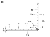
- FIG. 5 is a view seen from the direction of arrow A shown in FIG. FIG. 5 shows only a part of the first portion 51, the third portion 53, and the second beam member 2 of the connecting member 5.
- the third portion 53 is formed by bending the flat plate member 10 at a right angle to the inner surface 51a of the first portion 51.
- the second beam member 2 is arranged so that the inner surface 2a of the second beam member 2 comes into surface contact with the outer surface 51b of the first portion 51 and the outer surface 53b of the third portion 53.
- the second side 51d of the first portion 51 is located at the center of bending.
- the bending radius of the outer surface 51b on the second side 51d is R.
- the bending radius R corresponds to the radius of a circle C that draws a curve having the same size as the central portion of bending of the outer surface 51b.
- the bending radius R is made equal to the bending radius of the inner surface 2a of the second beam member 2.
- the equal bending radii means that the bending radii are substantially the same, and includes the case where the bending radii are approximated to the extent that surface contact can be secured.
- Equal bending radii means, for example, that the variation in bending radii is within ⁇ 10% of one value.
- the contact strength between the first portion 51 and the second beam member 2 can be improved also in the second side 51d portion, so that the joint strength between the connecting member 5 and the second beam member 2 can be increased. Can be improved.
- the first portion 51 and the third portion 53 when the thickness of the first portion 51 and the third portion 53 is d1 and the thickness of the second beam member 2 is d2, when the thickness d1 is reduced, the weight of the connecting member 5 is reduced, while the weight of the connecting member 5 is reduced.
- the strength of the first portion 51 and the third portion 53 is reduced.
- the first portion 51 and the third portion 53 can be reinforced by the second beam member 2.
- Each of the first portion 51 and the third portion 53 can be regarded as having a thickness corresponding to the sum of the thickness d1 and the thickness d2. According to this, even if the thickness d1 of the first portion 51 and the third portion 53 is reduced, the strength of the first portion 51 and the third portion 53 can be ensured.
- the bending radius of the outer surface 51b on the first side 51c is made equal to the bending radius of the inner surface 1a of the first beam member 1, so that the connecting members 5 and the first The joint strength with the beam member 1 can be improved.
- the bending radius of the outer surface 52b of the second portion 52 is made equal to the bending radius of the inner surface 3a of the column member 3, thereby improving the joint strength between the connecting member 5 and the column member 3. Can be made to. As a result, even if the thickness of the connecting member 5 is reduced, the connecting strength of the plurality of extending members connected by the connecting member 5 can be improved, and the strength of the housing 100 can be improved. That is, it is possible to reduce the weight of the connecting member 5 while ensuring the strength of the connecting member 5.
Landscapes
- Engineering & Computer Science (AREA)
- General Engineering & Computer Science (AREA)
- Mechanical Engineering (AREA)
- Microelectronics & Electronic Packaging (AREA)
- Connection Of Plates (AREA)
- Mutual Connection Of Rods And Tubes (AREA)
- Casings For Electric Apparatus (AREA)
- Furniture Connections (AREA)
- Joining Of Building Structures In Genera (AREA)
Abstract
Description
図3を参照して、連結部材5は、平板部材10に穴開け加工が施されるとともに平板部材10が曲げ加工されることにより、形成されている。平板部材10を構成する材料としては、たとえば軟鋼やステンレス鋼などの鋼板、アルミニウム板などを用いることができる。平板部材10の厚みは、たとえば1~3.5mm程度である。
Claims (7)
- 少なくとも2つの延在部材を互いに連結する連結部材であって、
直線状に延びる第1辺と、前記第1辺に直交して直線状に延びる第2辺とを有する平板状の第1部分と、
前記第1辺において前記第1部分に対して折れ曲がり、前記第1部分の内表面に対して垂直に延在する平板状の第2部分と、
前記第2辺において前記第1部分に対して折れ曲がり、前記第1部分の内表面に対して垂直に延在する平板状の第3部分と、
前記第2部分の内表面に対して垂直に突出するとともに前記第3部分と対向して配置される平板状のヒレ部とを備え、
前記第1辺における前記連結部材の外表面の曲げ半径は、第1の延在部材の前記第1辺に対向する側の面の曲げ半径と等しく、かつ、
前記第2辺における前記連結部材の外表面の曲げ半径は、第2の延在部材の前記第2辺に対向する側の面の曲げ半径と等しい、連結部材。 - 前記連結部材は、3つの延在部材を互いに連結するように構成され、
前記第2部分は、前記第1辺および前記第2辺に直交して直線状に延びる第3辺を有し、
前記ヒレ部は、前記第3辺において前記第2部分に対して折れ曲がり、前記第2部分の内表面に対して垂直に突出し、
前記第3辺における前記連結部材の外表面の曲げ半径は、第3の延在部材の前記第3辺に対向する側の面の曲げ半径に等しい、請求項1に記載の連結部材。 - 前記第1部分、前記第2部分、前記第3部分および前記ヒレ部は、平板部材の曲げ加工により形成される、請求項1または2に記載の連結部材。
- 前記第1部分、前記第2部分、前記第3部分および前記ヒレ部の各々には、前記第1および第2の延在部材を前記連結部材にリベット接合により連結するための、厚み方向に貫通する少なくとも1つの貫通孔が形成されている、請求項1から3のいずれか1項に記載の連結部材。
- 前記第2部分と前記第3部分との間に隙間が形成される、請求項1から4のいずれか1項に記載の連結部材。
- 水平方向に延在する梁部材と、
垂直方向に延在する柱部材と、
前記梁部材と前記柱部材とを連結する、請求項1から5のいずれか1項に記載の連結部材とを備える、筐体。 - 水平方向に延在する第1の梁部材と、
水平方向に延在する第2の梁部材と、
前記第1の梁部材と前記第2の梁部材とを連結する、請求項1から5のいずれか1項に記載の連結部材とを備える、筐体。
Priority Applications (5)
| Application Number | Priority Date | Filing Date | Title |
|---|---|---|---|
| JP2019560796A JP6938676B2 (ja) | 2019-06-21 | 2019-06-21 | 連結部材および筐体 |
| US17/283,175 US11933336B2 (en) | 2019-06-21 | 2019-06-21 | Coupling member and housing |
| CN201980067660.2A CN112888866A (zh) | 2019-06-21 | 2019-06-21 | 连结部件以及框体 |
| PCT/JP2019/024702 WO2020255374A1 (ja) | 2019-06-21 | 2019-06-21 | 連結部材および筐体 |
| KR1020217010354A KR102597790B1 (ko) | 2019-06-21 | 2019-06-21 | 연결 부재 및 하우징 |
Applications Claiming Priority (1)
| Application Number | Priority Date | Filing Date | Title |
|---|---|---|---|
| PCT/JP2019/024702 WO2020255374A1 (ja) | 2019-06-21 | 2019-06-21 | 連結部材および筐体 |
Publications (1)
| Publication Number | Publication Date |
|---|---|
| WO2020255374A1 true WO2020255374A1 (ja) | 2020-12-24 |
Family
ID=74040310
Family Applications (1)
| Application Number | Title | Priority Date | Filing Date |
|---|---|---|---|
| PCT/JP2019/024702 Ceased WO2020255374A1 (ja) | 2019-06-21 | 2019-06-21 | 連結部材および筐体 |
Country Status (5)
| Country | Link |
|---|---|
| US (1) | US11933336B2 (ja) |
| JP (1) | JP6938676B2 (ja) |
| KR (1) | KR102597790B1 (ja) |
| CN (1) | CN112888866A (ja) |
| WO (1) | WO2020255374A1 (ja) |
Cited By (1)
| Publication number | Priority date | Publication date | Assignee | Title |
|---|---|---|---|---|
| JP2022123386A (ja) * | 2021-02-12 | 2022-08-24 | 富士電機株式会社 | フレーム、及び電気盤 |
Families Citing this family (5)
| Publication number | Priority date | Publication date | Assignee | Title |
|---|---|---|---|---|
| WO2019195110A1 (en) * | 2018-04-04 | 2019-10-10 | Corning Research & Development Corporation | Sealing corner bracket and cabinet including corner bracket |
| EP4197918B1 (fr) * | 2021-12-16 | 2024-08-21 | Airbus Operations (S.A.S.) | Pièce de coin flexible destinée à contribuer à une liaison entre au moins trois parois d' au moins un caisson d' aéronef |
| CN114165505A (zh) * | 2021-12-31 | 2022-03-11 | 广东泰克萨斯机电设备有限公司 | 一种连接件结构、机箱以及连接件结构的加工方法 |
| KR20240148174A (ko) * | 2023-04-03 | 2024-10-11 | 현대자동차주식회사 | 연결용 조인트 및 이의 조립 방법 |
| US12274360B2 (en) * | 2023-07-17 | 2025-04-15 | Armadillo Tough LLC | Shelving post coupling system |
Citations (4)
| Publication number | Priority date | Publication date | Assignee | Title |
|---|---|---|---|---|
| JPS5163072U (ja) * | 1974-11-14 | 1976-05-18 | ||
| JP2004332254A (ja) * | 2003-05-01 | 2004-11-25 | Nakajima Steel Pipe Co Ltd | 鋼管柱を使用した鉄骨構造物 |
| JP2014081053A (ja) * | 2012-10-18 | 2014-05-08 | Toshiba Mitsubishi-Electric Industrial System Corp | 連結部材および筐体 |
| JP2015218806A (ja) * | 2014-05-16 | 2015-12-07 | 明電システム製造株式会社 | ガセット部材および枠構造体 |
Family Cites Families (24)
| Publication number | Priority date | Publication date | Assignee | Title |
|---|---|---|---|---|
| GB935434A (en) * | 1960-03-01 | 1963-08-28 | Alfred Imhof Ltd | Improvements in or relating to rigid frameworks for use in constructing racks, cabinets, boxes or the like |
| FR1601944A (ja) * | 1968-12-31 | 1970-09-21 | ||
| US3877138A (en) * | 1971-08-25 | 1975-04-15 | Hartz Mountain Corp | Method of making miter frame corner construction |
| US3919603A (en) * | 1973-02-21 | 1975-11-11 | Westinghouse Electric Corp | Switchboard framework corner tie |
| GB1552695A (en) * | 1976-06-02 | 1979-09-19 | Standard Telephones Cables Ltd | Frameworks |
| GB2185272A (en) * | 1985-12-16 | 1987-07-15 | Sean Cavanagh | Demountable staging |
| GB2232426B (en) * | 1989-06-08 | 1993-11-17 | Square D Co | Framework assembly system |
| JPH07317733A (ja) * | 1994-05-30 | 1995-12-08 | Shin Kobe Electric Mach Co Ltd | 筐体のコーナー部材 |
| DE19613586A1 (de) * | 1996-04-04 | 1997-10-09 | Gerhard Ries | Verfahren zum Herstellen einer Verbindungsvorrichtung |
| US6022165A (en) * | 1997-10-30 | 2000-02-08 | Simpson Strong-Tie Company, Inc. | Rigid internal connector |
| JP3804321B2 (ja) * | 1999-01-18 | 2006-08-02 | いすゞ自動車株式会社 | 車両のシャシフレーム衝突安全構造 |
| JP2000324624A (ja) | 1999-04-30 | 2000-11-24 | Mitsubishi Electric Corp | 筐体の骨構造 |
| FR2798520B1 (fr) * | 1999-09-15 | 2003-10-17 | Schneider Electric Ind Sa | Chassis equipe d'une ossature metallique a coin de serrage progressif, notamment pour une armoire electrique |
| JP2001239903A (ja) * | 2000-02-29 | 2001-09-04 | Katayama Kogyo Co Ltd | 車両用バンパ |
| JP4053213B2 (ja) | 2000-06-09 | 2008-02-27 | 三菱電機株式会社 | 筐体のフレーム構造 |
| US6962262B2 (en) * | 2003-02-10 | 2005-11-08 | Dennis Toma | Connecting corner for knock down racks |
| US20060182492A1 (en) * | 2005-02-01 | 2006-08-17 | Adam's Specialty Products, Llc | Draw-wedge fasteners |
| JP2007131148A (ja) * | 2005-11-10 | 2007-05-31 | Toyota Motor Corp | 車体下部構造 |
| CN2888153Y (zh) * | 2005-11-30 | 2007-04-11 | 英业达股份有限公司 | 金属板的接合结构 |
| JP2009144848A (ja) | 2007-12-17 | 2009-07-02 | Hirata Corp | フレーム構造体 |
| JP5299170B2 (ja) * | 2009-08-25 | 2013-09-25 | トヨタ自動車株式会社 | 車体構造 |
| JP5484175B2 (ja) * | 2010-04-23 | 2014-05-07 | 本田技研工業株式会社 | 車両のセンターピラー構造 |
| JP2012085913A (ja) | 2010-10-21 | 2012-05-10 | Go Owada | キャビネットボックス |
| DE102016011887B3 (de) * | 2016-10-04 | 2017-07-20 | Gerhard Niedermeier | Eckverbindung dreier balkenförmiger Elemente, Verbindungselement und Lager-, Transport oder Rahmengestell oder Skelettrahmen |
-
2019
- 2019-06-21 US US17/283,175 patent/US11933336B2/en active Active
- 2019-06-21 KR KR1020217010354A patent/KR102597790B1/ko active Active
- 2019-06-21 WO PCT/JP2019/024702 patent/WO2020255374A1/ja not_active Ceased
- 2019-06-21 CN CN201980067660.2A patent/CN112888866A/zh active Pending
- 2019-06-21 JP JP2019560796A patent/JP6938676B2/ja active Active
Patent Citations (4)
| Publication number | Priority date | Publication date | Assignee | Title |
|---|---|---|---|---|
| JPS5163072U (ja) * | 1974-11-14 | 1976-05-18 | ||
| JP2004332254A (ja) * | 2003-05-01 | 2004-11-25 | Nakajima Steel Pipe Co Ltd | 鋼管柱を使用した鉄骨構造物 |
| JP2014081053A (ja) * | 2012-10-18 | 2014-05-08 | Toshiba Mitsubishi-Electric Industrial System Corp | 連結部材および筐体 |
| JP2015218806A (ja) * | 2014-05-16 | 2015-12-07 | 明電システム製造株式会社 | ガセット部材および枠構造体 |
Cited By (2)
| Publication number | Priority date | Publication date | Assignee | Title |
|---|---|---|---|---|
| JP2022123386A (ja) * | 2021-02-12 | 2022-08-24 | 富士電機株式会社 | フレーム、及び電気盤 |
| JP7600734B2 (ja) | 2021-02-12 | 2024-12-17 | 富士電機株式会社 | フレーム、及び電気盤 |
Also Published As
| Publication number | Publication date |
|---|---|
| US20210341005A1 (en) | 2021-11-04 |
| US11933336B2 (en) | 2024-03-19 |
| JP6938676B2 (ja) | 2021-09-22 |
| CN112888866A (zh) | 2021-06-01 |
| JPWO2020255374A1 (ja) | 2021-09-13 |
| KR102597790B1 (ko) | 2023-11-02 |
| KR20210057769A (ko) | 2021-05-21 |
Similar Documents
| Publication | Publication Date | Title |
|---|---|---|
| JP6938676B2 (ja) | 連結部材および筐体 | |
| TWI237082B (en) | A beam coupling device | |
| JP5428679B2 (ja) | 閉鎖形配電盤のフレーム組立構造 | |
| JP2005527421A (ja) | 三次元連結構造 | |
| CN102639388B (zh) | 结构体 | |
| JP5801784B2 (ja) | 連結部材および筐体 | |
| JP2010064549A (ja) | 車体骨格部材 | |
| JP7173940B2 (ja) | 構造部材 | |
| JP2004168073A (ja) | 車体上部構造 | |
| CN108457373B (zh) | 负荷支撑部件 | |
| JP5724655B2 (ja) | 連結金具及びこれを備えたフレーム並びにこのフレームを用いた建築物 | |
| JP2001019319A (ja) | 床構造 | |
| JP2018085355A (ja) | 嵌め込みフレーム構造体および筐体 | |
| JP5216057B2 (ja) | 乗客コンベア | |
| JP7355727B2 (ja) | 車両用フード構造 | |
| JP2018016978A (ja) | 構造部材 | |
| JP2002004634A (ja) | 制震構造及び制震装置 | |
| JP2006175469A (ja) | パイプ連結構造 | |
| JP6775324B2 (ja) | ブレース接合構造 | |
| JPH0827952A (ja) | 角形鋼管柱 | |
| JP7311389B2 (ja) | 梁材 | |
| CN109386525B (zh) | 由柱以及梁构成的结构体的加强结构以及加强部件 | |
| JP2019093833A (ja) | 車両用トランクリッドパネル | |
| JP2025105949A (ja) | 架構補強構造 | |
| JP2007107280A (ja) | ブレース型粘弾性ダンパー |
Legal Events
| Date | Code | Title | Description |
|---|---|---|---|
| ENP | Entry into the national phase |
Ref document number: 2019560796 Country of ref document: JP Kind code of ref document: A |
|
| 121 | Ep: the epo has been informed by wipo that ep was designated in this application |
Ref document number: 19933679 Country of ref document: EP Kind code of ref document: A1 |
|
| ENP | Entry into the national phase |
Ref document number: 20217010354 Country of ref document: KR Kind code of ref document: A |
|
| NENP | Non-entry into the national phase |
Ref country code: DE |
|
| 122 | Ep: pct application non-entry in european phase |
Ref document number: 19933679 Country of ref document: EP Kind code of ref document: A1 |