WO2020251052A1 - ドラムユニット、駆動伝達ユニット、カートリッジおよび電子写真画像形成装置 - Google Patents
ドラムユニット、駆動伝達ユニット、カートリッジおよび電子写真画像形成装置 Download PDFInfo
- Publication number
- WO2020251052A1 WO2020251052A1 PCT/JP2020/023319 JP2020023319W WO2020251052A1 WO 2020251052 A1 WO2020251052 A1 WO 2020251052A1 JP 2020023319 W JP2020023319 W JP 2020023319W WO 2020251052 A1 WO2020251052 A1 WO 2020251052A1
- Authority
- WO
- WIPO (PCT)
- Prior art keywords
- coupling
- coupling portion
- drum
- drive transmission
- respect
- Prior art date
- Legal status (The legal status is an assumption and is not a legal conclusion. Google has not performed a legal analysis and makes no representation as to the accuracy of the status listed.)
- Ceased
Links
Images


Classifications
-
- G—PHYSICS
- G03—PHOTOGRAPHY; CINEMATOGRAPHY; ANALOGOUS TECHNIQUES USING WAVES OTHER THAN OPTICAL WAVES; ELECTROGRAPHY; HOLOGRAPHY
- G03G—ELECTROGRAPHY; ELECTROPHOTOGRAPHY; MAGNETOGRAPHY
- G03G15/00—Apparatus for electrographic processes using a charge pattern
- G03G15/75—Details relating to xerographic drum, band or plate, e.g. replacing, testing
-
- G—PHYSICS
- G03—PHOTOGRAPHY; CINEMATOGRAPHY; ANALOGOUS TECHNIQUES USING WAVES OTHER THAN OPTICAL WAVES; ELECTROGRAPHY; HOLOGRAPHY
- G03G—ELECTROGRAPHY; ELECTROPHOTOGRAPHY; MAGNETOGRAPHY
- G03G21/00—Arrangements not provided for by groups G03G13/00 - G03G19/00, e.g. cleaning, elimination of residual charge
- G03G21/16—Mechanical means for facilitating the maintenance of the apparatus, e.g. modular arrangements
- G03G21/18—Mechanical means for facilitating the maintenance of the apparatus, e.g. modular arrangements using a processing cartridge, whereby the process cartridge comprises at least two image processing means in a single unit
- G03G21/1839—Means for handling the process cartridge in the apparatus body
- G03G21/1857—Means for handling the process cartridge in the apparatus body for transmitting mechanical drive power to the process cartridge, drive mechanisms, gears, couplings, braking mechanisms
- G03G21/186—Axial couplings
-
- G—PHYSICS
- G03—PHOTOGRAPHY; CINEMATOGRAPHY; ANALOGOUS TECHNIQUES USING WAVES OTHER THAN OPTICAL WAVES; ELECTROGRAPHY; HOLOGRAPHY
- G03G—ELECTROGRAPHY; ELECTROPHOTOGRAPHY; MAGNETOGRAPHY
- G03G15/00—Apparatus for electrographic processes using a charge pattern
- G03G15/75—Details relating to xerographic drum, band or plate, e.g. replacing, testing
- G03G15/757—Drive mechanisms for photosensitive medium, e.g. gears
-
- G—PHYSICS
- G03—PHOTOGRAPHY; CINEMATOGRAPHY; ANALOGOUS TECHNIQUES USING WAVES OTHER THAN OPTICAL WAVES; ELECTROGRAPHY; HOLOGRAPHY
- G03G—ELECTROGRAPHY; ELECTROPHOTOGRAPHY; MAGNETOGRAPHY
- G03G21/00—Arrangements not provided for by groups G03G13/00 - G03G19/00, e.g. cleaning, elimination of residual charge
- G03G21/16—Mechanical means for facilitating the maintenance of the apparatus, e.g. modular arrangements
- G03G21/1642—Mechanical means for facilitating the maintenance of the apparatus, e.g. modular arrangements for connecting the different parts of the apparatus
- G03G21/1647—Mechanical connection means
-
- G—PHYSICS
- G03—PHOTOGRAPHY; CINEMATOGRAPHY; ANALOGOUS TECHNIQUES USING WAVES OTHER THAN OPTICAL WAVES; ELECTROGRAPHY; HOLOGRAPHY
- G03G—ELECTROGRAPHY; ELECTROPHOTOGRAPHY; MAGNETOGRAPHY
- G03G21/00—Arrangements not provided for by groups G03G13/00 - G03G19/00, e.g. cleaning, elimination of residual charge
- G03G21/16—Mechanical means for facilitating the maintenance of the apparatus, e.g. modular arrangements
- G03G21/1661—Mechanical means for facilitating the maintenance of the apparatus, e.g. modular arrangements means for handling parts of the apparatus in the apparatus
- G03G21/1671—Mechanical means for facilitating the maintenance of the apparatus, e.g. modular arrangements means for handling parts of the apparatus in the apparatus for the photosensitive element
-
- G—PHYSICS
- G03—PHOTOGRAPHY; CINEMATOGRAPHY; ANALOGOUS TECHNIQUES USING WAVES OTHER THAN OPTICAL WAVES; ELECTROGRAPHY; HOLOGRAPHY
- G03G—ELECTROGRAPHY; ELECTROPHOTOGRAPHY; MAGNETOGRAPHY
- G03G21/00—Arrangements not provided for by groups G03G13/00 - G03G19/00, e.g. cleaning, elimination of residual charge
- G03G21/16—Mechanical means for facilitating the maintenance of the apparatus, e.g. modular arrangements
- G03G21/18—Mechanical means for facilitating the maintenance of the apparatus, e.g. modular arrangements using a processing cartridge, whereby the process cartridge comprises at least two image processing means in a single unit
- G03G21/1803—Arrangements or disposition of the complete process cartridge or parts thereof
- G03G21/1814—Details of parts of process cartridge, e.g. for charging, transfer, cleaning, developing
-
- G—PHYSICS
- G03—PHOTOGRAPHY; CINEMATOGRAPHY; ANALOGOUS TECHNIQUES USING WAVES OTHER THAN OPTICAL WAVES; ELECTROGRAPHY; HOLOGRAPHY
- G03G—ELECTROGRAPHY; ELECTROPHOTOGRAPHY; MAGNETOGRAPHY
- G03G21/00—Arrangements not provided for by groups G03G13/00 - G03G19/00, e.g. cleaning, elimination of residual charge
- G03G21/16—Mechanical means for facilitating the maintenance of the apparatus, e.g. modular arrangements
- G03G21/18—Mechanical means for facilitating the maintenance of the apparatus, e.g. modular arrangements using a processing cartridge, whereby the process cartridge comprises at least two image processing means in a single unit
- G03G21/1839—Means for handling the process cartridge in the apparatus body
- G03G21/1842—Means for handling the process cartridge in the apparatus body for guiding and mounting the process cartridge, positioning, alignment, locks
- G03G21/1853—Means for handling the process cartridge in the apparatus body for guiding and mounting the process cartridge, positioning, alignment, locks the process cartridge being mounted perpendicular to the axis of the photosensitive member
-
- G—PHYSICS
- G03—PHOTOGRAPHY; CINEMATOGRAPHY; ANALOGOUS TECHNIQUES USING WAVES OTHER THAN OPTICAL WAVES; ELECTROGRAPHY; HOLOGRAPHY
- G03G—ELECTROGRAPHY; ELECTROPHOTOGRAPHY; MAGNETOGRAPHY
- G03G21/00—Arrangements not provided for by groups G03G13/00 - G03G19/00, e.g. cleaning, elimination of residual charge
- G03G21/16—Mechanical means for facilitating the maintenance of the apparatus, e.g. modular arrangements
- G03G21/18—Mechanical means for facilitating the maintenance of the apparatus, e.g. modular arrangements using a processing cartridge, whereby the process cartridge comprises at least two image processing means in a single unit
- G03G21/1839—Means for handling the process cartridge in the apparatus body
- G03G21/1857—Means for handling the process cartridge in the apparatus body for transmitting mechanical drive power to the process cartridge, drive mechanisms, gears, couplings, braking mechanisms
-
- G—PHYSICS
- G03—PHOTOGRAPHY; CINEMATOGRAPHY; ANALOGOUS TECHNIQUES USING WAVES OTHER THAN OPTICAL WAVES; ELECTROGRAPHY; HOLOGRAPHY
- G03G—ELECTROGRAPHY; ELECTROPHOTOGRAPHY; MAGNETOGRAPHY
- G03G2221/00—Processes not provided for by group G03G2215/00, e.g. cleaning or residual charge elimination
- G03G2221/16—Mechanical means for facilitating the maintenance of the apparatus, e.g. modular arrangements and complete machine concepts
- G03G2221/1651—Mechanical means for facilitating the maintenance of the apparatus, e.g. modular arrangements and complete machine concepts for connecting the different parts
- G03G2221/1657—Mechanical means for facilitating the maintenance of the apparatus, e.g. modular arrangements and complete machine concepts for connecting the different parts transmitting mechanical drive power
Definitions
- the present invention relates to a drum unit, a drive transmission unit, a cartridge, and an electrophotographic image forming apparatus.
- An electrophotographic image forming apparatus is an apparatus that forms an image on a recording medium by using an electrophotographic image forming process.
- electrocopiers electrophotographic printers (LED printers, laser beam printers, etc.), facsimile machines, word processors, and the like are included.
- the cartridge is detachably attached to the main body of the electrophotographic image forming apparatus.
- the drum unit is a unit having a photoconductor drum.
- the drive transmission unit is a unit having a coupling member.
- an electrophotographic photosensitive member generally a drum type as an image carrier, that is, a photoconductor drum (electrophotographic photosensitive member drum) is used. It is charged like this.
- an electrostatic latent image electrostatic image
- the electrostatic latent image formed on the photoconductor drum is developed as a toner image with toner as a developer.
- the toner image formed on the photoconductor drum is transferred to a recording material such as recording paper or a plastic sheet. Further, by applying heat or pressure to the toner image transferred onto the recording material, the toner image is fixed on the recording material to perform image recording.
- Such an image forming apparatus generally requires toner replenishment and maintenance of various process means.
- a photoconductor drum, charging means, developing means, cleaning means, etc. are integrated into a unit inside the frame to form a cartridge that can be attached to and detached from the image forming apparatus main body. ing.
- a part of the image forming device unit can be attached to and detached from the device body like this cartridge, the user can perform a part of the maintenance of the device by himself / herself without relying on the service person in charge of after-sales service. be able to. Therefore, the operability of the device can be remarkably improved, and an image forming device having excellent usability can be provided. Therefore, such a cartridge method is widely used in an image forming apparatus.
- a process cartridge in which a photoconductor drum and a process means acting on the photoconductor drum are integrated is known.
- a configuration in which a coupling member is provided at the tip of the photoconductor drum to transmit the driving force from the apparatus main body to the photoconductor drum is widely used (Japanese Patent Laid-Open No. 2017-223802). ..
- the present invention is to further develop the above-mentioned conventional technique.
- Typical configurations disclosed in this application are: In the drum unit used for the cartridge Photoreceptor drum and A coupling member arranged near the end of the photoconductor drum and connected to the photoconductor drum so as to be drive-transmitted.
- the coupling member is a drum unit configured to be tiltable with respect to the rotation axis of the photoconductor drum and to reduce the tilt angle of the photoconductor drum with respect to the rotation axis as the photoconductor drum is driven to rotate. is there.
- a drive transmission unit that can be attached to the main body of an electrophotographic image forming apparatus.
- Coupling member and A support member that supports the coupling member and Have The coupling member is a drive transmission unit that is tiltable with respect to the rotation axis of the support member and is configured to reduce the inclination angle of the support member with respect to the rotation axis as it is driven. ..
- Another typical configuration disclosed in the present application is a cartridge including the above-mentioned drum unit and drive transmission unit, and an electrophotographic image forming apparatus.
- FIG. 1 is a diagram illustrating a configuration of an image forming apparatus main body and a process cartridge.
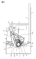
- FIG. 2 is a cross-sectional view of the image forming apparatus main body and the process cartridge.
- FIG. 3 is a cross-sectional view of the process cartridge.
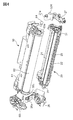
- FIG. 4 is an exploded perspective view of the process cartridge.
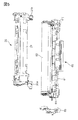
- FIG. 5 is an exploded perspective view of the process cartridge.
- FIG. 6 is a cross-sectional view of the image forming apparatus main body and the process cartridge.
- FIG. 7 is an explanatory view of the image forming apparatus main body.
- FIG. 8 is an exploded perspective view of the drum unit.
- FIG. 9 is a perspective view of the process cartridge.
- FIG. 10 is a cross-sectional view of the image forming apparatus main body and the process cartridge.
- FIG. 11 is an explanatory diagram of the coupling unit.
- FIG. 12 is a perspective view of the image forming apparatus main body.
- FIG. 13 is an exploded perspective view of the drum flange unit.
- FIG. 14 is a cross-sectional view of the image forming apparatus main body and the process cartridge.
- FIG. 15 is an explanatory diagram of the coupling unit.
- FIG. 16 is a cross-sectional view of the drive transmission unit and the non-drive transmission unit.
- the direction of the rotation axis of the electrophotographic photosensitive member drum is the longitudinal direction.
- the side where the electrophotographic photosensitive drum receives the driving force from the image forming apparatus main body is the driving side, and the opposite side is the non-driving side.
- FIG. 2 is a cross-sectional view of an apparatus main body (electrophotographic image forming apparatus main body, image forming apparatus main body) A and a process cartridge (hereinafter referred to as cartridge B) of the electrophotographic image forming apparatus according to the first embodiment. is there.
- FIG. 3 is a cross-sectional view of the cartridge B.
- the apparatus main body A is a portion of the electrophotographic image forming apparatus excluding the cartridge B. ⁇ Overall configuration of electrophotographic image forming apparatus>
- the electrophotographic image forming apparatus (image forming apparatus) shown in FIG. 2 is a laser beam printer using electrophotographic technology in which the cartridge B is detachably attached to and attached to the apparatus main body A.
- an exposure apparatus 3 laser scanner unit
- a sheet tray 4 containing a recording medium hereinafter, referred to as a sheet material PA
- the electrophotographic photosensitive member drum 62 is a photosensitive member (electrophotographic photosensitive member) used for forming an electrophotographic image.
- the apparatus main body A includes a pickup roller 5a, a feeding roller pair 5b, a transfer guide 6, a transfer roller 7, a transport guide 8, a fixing device 9, and a discharge roller pair 10 along the transport direction C of the sheet material PA. Discharge trays 11 and the like are sequentially arranged.
- the fixing device 9 is composed of a heating roller 9a and a pressure roller 9b.
- the electrophotographic photosensitive member drum (hereinafter, referred to as the photosensitive member drum 62 or simply the drum 62) is rotationally driven in the arrow R direction at a predetermined peripheral speed (process speed).
- the charging roller (charging member) 66 to which the bias voltage is applied comes into contact with the outer peripheral surface of the drum 62 and charges the outer peripheral surface of the drum 62 uniformly and uniformly.
- the exposure device 3 outputs the laser beam L according to the image information.
- the laser beam L passes through the laser opening 61h provided in the cleaning frame 61 of the cartridge B, and scans and exposes the outer peripheral surface of the drum 62. As a result, an electrostatic latent image corresponding to the image information is formed on the outer peripheral surface of the drum 62.
- the toner T in the toner chamber 28 is agitated and conveyed by the rotation of the conveying member (stirring member) 30 and sent out to the toner supply chamber 29.
- the toner T is supported on the surface of the developing roller 23 by the magnetic force of the magnet roller 24 (fixed magnet).
- the developing roller 23 is a developer carrier that supports a developer (toner T) on its surface in order to develop a latent image formed on the drum 62.
- the toner T is triboelectrically charged by the developing blade 25, and the layer thickness on the peripheral surface of the developing roller 23 as the developing agent carrier is regulated.
- the toner T is supplied to the drum 62 according to the electrostatic latent image to develop the latent image.
- the drum 62 is an image carrier that carries a latent image or an image formed of toner (toner image, developer image) on its surface.
- the sheet material PA stored in the lower part of the apparatus main body A is sent out from the seat tray 4 by the pickup roller 5a and the feeding roller pair 5b together with the output timing of the laser beam L. Then, the sheet material PA is conveyed to the transfer position between the drum 62 and the transfer roller 7 via the transfer guide 6. At this transfer position, the toner image is sequentially transferred from the drum 62 to the sheet material PA.
- the sheet material PA to which the toner image is transferred is separated from the drum 62 and conveyed to the fixing device 9 along the conveying guide 8. Then, the sheet material PA passes through the nip portion of the heating roller 9a and the pressurizing roller 9b constituting the fixing device 9. Pressurization / heat fixing treatment is performed at this nip portion, and the toner image is fixed to the sheet material PA.
- the sheet material PA that has undergone the toner image fixing process is conveyed to the discharge roller pair 10 and discharged to the discharge tray 11.
- the drum 62 after transfer is used again in the image forming process after the residual toner on the outer peripheral surface is removed by the cleaning member 65. It is stored in the waste toner chamber 61b of the toner cleaning unit 60 removed from the drum 62.
- the cleaning unit 60 is a unit having a photoconductor drum 62.
- the charging roller 66, the developing roller 23, the transfer roller 7, and the cleaning member 65 are process means for acting on the drum 62. ⁇ Structure of the entire cartridge>
- FIG. 3 is a cross-sectional view of the cartridge B
- FIGS. 4 and 5 are perspective views illustrating the configuration of the cartridge B.
- the screws for connecting the parts will be omitted.
- Cartridge B has a cleaning unit.
- the cleaning unit 60 includes a drum 62, a charging roller 66, a cleaning member 65, and a cleaning frame 61 that supports them.
- the drive side drum flange 71 provided on the drive side is rotatably supported by the hole portion 69a of the drum bearing 69.
- the drum bearing 69 and the cleaning frame 61 can also be collectively referred to as a cleaning frame.
- the hole 63a of the non-driving side drum flange 63 is formed by the drum shaft 64 press-fitted into the hole 61c provided in the cleaning frame 61 (see FIG. 8E). Is rotatably supported.
- the charging roller 66 and the cleaning member 65 are arranged in contact with the outer peripheral surface of the drum 62, respectively.
- the cleaning member 65 includes a rubber blade 65a, which is a blade-shaped elastic member formed of rubber as an elastic material, and a support member 65b that supports the rubber blade.
- the rubber blade 65a is in contact with the drum 62 in the counter direction with respect to the rotation direction of the drum 62. That is, the rubber blade 65a is in contact with the drum 62 so that its tip portion faces the upstream side in the rotation direction of the drum 62.
- the waste toner removed from the surface of the drum 62 by the cleaning member 65 is stored in the waste toner chamber 61b formed by the cleaning frame 61 and the cleaning member 65.
- a squeeze sheet 34 for preventing waste toner from leaking from the cleaning frame 61 is provided at the edge of the cleaning frame 61 so as to abut the drum 62.
- the charging roller 66 is rotatably attached to the cleaning unit 60 via a charging roller bearing (not shown) at both ends of the cleaning frame 61 in the longitudinal direction.
- the longitudinal direction of the cleaning frame 61 (longitudinal direction of the cartridge B) is a direction parallel to the rotation axis of the drum 62 (axial direction). Therefore, hereinafter, the axial direction of the drum 62 is intended in the case of simply longitudinal direction or simply axial direction without particular notice.
- the charging roller 66 is pressed against the drum 62 by pressing the charging roller bearing 67 toward the drum 62 by the charging roller urging member 68.
- the charging roller 66 is driven by the rotation of the drum 62.
- the developing unit 20 includes a developing roller 23, a developing container 21 that supports the developing roller 23, a developing blade 25, and the like.
- the developing roller 23 is rotatably attached to the developing container 21 by a driving side bearing member 26 and a non-driving side bearing member 27 provided at both ends.
- a magnet roller 24 is provided in the developing roller 23.
- a developing blade 25 for regulating the toner layer on the developing roller 23 is arranged.
- the developing roller 23 is attached to both ends of the spacing member 31 developing roller 23, and when the spacing member 31 and the drum 62 come into contact with each other, the developing roller 23 has a small gap with the drum 62. Is held with.
- a blowout prevention sheet 33 for preventing toner from leaking from the developing unit 20 is provided at the edge of the bottom member 22 so as to come into contact with the developing roller 23.
- a transport member 30 is provided in the toner chamber 28 formed by the developing container 21 and the bottom member 22. The transport member 30 agitates the toner contained in the toner chamber 28 and transports the toner to the toner supply chamber 29.
- the cartridge B is configured by combining the cleaning unit 60 and the developing unit 20.
- Each of the provided support bosses 27a is fitted.
- the developing unit 20 is rotatably connected to the cleaning unit 60 (rotatably).
- the cartridge B is formed by assembling the drum bearing 69 to the cleaning unit 60.
- the drive side urging member 32L and the non-drive side urging member 32R are formed of compression springs. The urging force of these springs urges the developing unit 20 to the cleaning unit 60, and the developing roller 23 is reliably pressed in the direction of the drum 62. Then, the developing roller 23 is held from the drum 62 at a predetermined interval by the spacing members 31 attached to both ends of the developing roller 23. ⁇ Cartridge mounting operation>
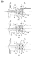
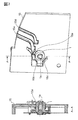
- FIG. 1A shows the state of the drive transmission member (drive shaft, drive output member) 1 and the drive side drum flange unit (drive transmission unit) 70 when the cartridge B is mounted on the apparatus main body A and is not driven.
- FIG. 6A is a cross-sectional view of a state in which the cartridge B is mounted on the apparatus main body A.
- FIG. 6B is a cross-sectional view showing a state in which the cartridge B has been mounted on the apparatus main body A.
- FIG. 7 is an explanatory view showing a state of the drive transmission member 1 before the cartridge B is mounted on the apparatus main body A.
- the cartridge B is first attached to the device main body A by rotating the opening / closing door 13 of the device main body A around a rotation center (not shown).
- the guided portions 69d and 69e of the cartridge B are inserted along the guide rails 15d and 15e (only the drive side is shown).
- the positioned portions 69b and 69c provided on the drum bearing member 69 are brought into contact with the apparatus main body positioning portions 15b and 15c, or are inserted to the vicinity thereof. It is completed by.
- Two cartridge pressing members 17 are rotatably attached to the vicinity of both ends of the opening / closing door 13 in the axial direction.
- the two cartridge pressing springs 19 are attached to both ends in the longitudinal direction of the apparatus main body A.
- the cleaning frame 61 is provided with cartridge pressed portions 61e as urging force receiving portions of the cartridge pressing spring 19 at both longitudinal ends.
- a predetermined force is applied to the cartridge pressed portion 61e from the cartridge pressing spring 19.
- the positioned portions 69b and 69c are maintained in contact with the apparatus main body positioning portions 15b and 15c, and the cartridge B is arranged at a position where an image can be formed (FIG. 6B).
- one end of the drive transmission member 1 is temporarily supported in the hole portion 15a of the drive side plate 15 of the drive transmission member 1.
- the drive transmission member Before mounting the cartridge B, the drive transmission member is tilted by its own weight within the range of play (gap) generated between the hole portion 15a and the drive transmission member 1.
- the first coupling portion 72 is attached with a third urging member 76 (coupling urging member, third elastic member, third spring) (FIG. 9) in order to engage with the drive transmission member 1. Depending on the force, it tilts in approximately the same direction as the drive transmission member 1.
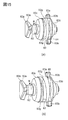
- 8 (a), 8 (b), and (c) are diagrams illustrating a method of assembling the coupling unit 79.
- FIG. 8D is a diagram illustrating a method of assembling the drive-side drum flange unit 70.
- FIG. 8E is a diagram illustrating a method of assembling the drum unit.
- FIG. 9 is a perspective view showing the configuration of the first coupling portion 72 and the third urging member (third elastic member, third spring) 76.
- FIG. 10 is a cross-sectional view showing a state of the drive transmission member 1 and the drive side drum flange unit 70 when the cartridge B is mounted on the apparatus main body A and is not driven.
- Each member that rotates with the photoconductor drum 62 is called a drum unit.
- the drum unit includes a photoconductor drum 62, a drive-side drum flange unit 70, and a non-drive-side drum flange 63.
- a drive-side drum flange unit 70 is fixed to one end of the photoconductor drum, and a non-drive-side drum flange 63 is fixed to the other end (second end) of the photoconductor drum opposite to the one end.
- the drive-side drum flange unit 70 includes a drive-side drum flange 71, a first coupling portion 72, a second coupling portion 73, and a first urging member 74 (first elastic member, first spring, axial urging member). ), The second urging member 75 (the second elastic member, the second spring, the radial urging member), the pin 78, and the lid member 77.
- the first coupling portion 72 is provided with a driven transmission portion (driving force receiving portion) 72a to which a driving force is transmitted from the drive transmitting member 1 of the apparatus main body A.
- the first coupling portion 72 transmits a driving force to the second coupling portion 73 via the pin 78 (second contact portion).
- the first coupling portion 72 and the pin 78 may be integrated.
- the second coupling portion 73 includes a driven transmission portion 73a (second contacted portion) in which the driving force is transmitted from the first coupling portion 72, and a drive transmission unit 73b (second) for transmitting the drive to the lid member 77.
- the contact portion of 1) is provided.
- the lid member 77 is provided with a driven transmission portion 77a (first contacted portion) to which a driving force is transmitted from the second coupling portion 73.
- the shaft portion 72k of the first coupling portion 72 and the second coupling portion 73 is inserted into the hole portion 73k, and the second coupling portion 73 with respect to the first coupling portion 72. Is rotatably supported.
- a second urging member 75 for urging in the rotational direction is arranged between the first coupling portion 72 and the second coupling portion 73.
- the second urging member 75 is composed of a torsion coil spring, and both ends of the spring abut on the spring hooking portion 72h of the first coupling portion 72 and the spring hooking portion 73h of the second coupling portion 73, respectively, in the rotation direction. Regulate the movement of.
- the coupling unit (coupling member) 79 is configured by penetrating the pin 78 through the pin insertion holes 72d and 73d, respectively.
- a first urging member 74 for urging the coupling unit 79 to the drive side is provided. Will be inserted.
- the lid member 77 is fixed to the drive-side drum flange 71 by means such as welding to form the drive-side drum flange unit 70.
- the drive-side drum flange unit 70 and the non-drive-side drum flange 63 are inserted into the drum 62 and fixed by means such as press fitting or caulking.
- the drum unit (62, 70, 63) configured in this way is rotatably supported by the frame body (drum bearing 69) of the cartridge B.
- the drum unit (62, 70, 73) can be attached to the apparatus main body A as a part of the cartridge B.
- the pin 78, the first coupling portion 72, and the second coupling portion 73 of the drum unit are collectively referred to as a coupling member.
- the coupling coupling member (72, 73, 78) is connected to a drive transmission member (described later) of the device body A to transmit a drive force (rotational force) from the device body A toward the drum 62. It is a member.
- the coupling member is a unit that can be disassembled into a plurality of members (78, 72, 73), but the configuration is not limited to this, and the coupling member may be composed of one body.
- the first coupling portion 72 and the second coupling portion 73 may originally be composed of one component. sell. Such a configuration will be described later.
- the lid member 77 and the drive-side drum flange 71 may be collectively referred to as a flange member, or the lid member 77 may be regarded as a part of the drive-side drum flange 71.
- the flange member (71, 77) is fixed to one end of the drum 62, and the drum 62 and the coupling member (72, 73, 78) are connected so as to be drive-transmissible.
- the flange member is an end member attached to the end of the drum 62.
- the coupling member (72, 73, 78) is arranged near the end portion of the photoconductor drum 62.
- the flange member (71, 77) transmits a driving force from the coupling member (72, 73, 78) to the drum 62.
- the flange members (71, 77) are cartridge-side transmission members (driving force transmitting members) that transmit the driving force.
- the flange member (71, 77) is also a connecting member that connects the coupling member (72, 73, 78) to the drum 62.
- the coupling member (72, 73, 78) is indirectly connected to the drum 62 via the flange member (71, 77).
- the coupling member is connected to the drum 62 so that the drive can be transmitted.
- the coupling members (72, 73, 78) are operatively connected to the drum 62. That is, as the coupling members (72, 73, 78) are rotationally driven, the drum 62 is also rotationally driven (operated).
- the coupling member (72, 73, 78) is supported by the flange member (71, 77) so as to be tiltable.
- the flange members (71, 77) are also support members that support the coupling members.
- the driven transmission unit (driving force receiving unit, drive input unit) 72a of the first coupling unit 72 adopts a substantially triangular cross section and a convex shape (see FIG. 16). Specifically, a shape in which a substantially triangular cross section is twisted counterclockwise on the axis of the drum 62 from the driving side to the non-driving side is adopted.
- a chamfered portion 72e inclined in the longitudinal direction is provided on the triangular ridgeline of the drive side end portion of the first coupling portion 72.
- the size of the chamfered portion 72e is such that when the drive transmission member 1 is inclined in the V direction due to its own weight, a part of the chamfered portion 72e is the drive transmission member 1 in the radial direction. It is located in the drive transmission unit 1a.
- the minimum distance D1 from the drum center axis to the chamfered portion 72e is set to be smaller than the distance D2 from the drum center axis to the inlet of the drive transmission portion of the drive transmission member 1.
- the drive transmission portion 73b of the second coupling portion 73 and the driven transmission portion (driving force receiving portion) 77a of the lid member 77 are engaged with each other, and the cross section of the drive transmission portion 73b is substantially triangular. ..
- the first urging member 74 brings the first coupling portion 72 closer to the drive side in the longitudinal direction (direction of arrow G).
- the spherical regulated portion 72c of the first coupling portion 72 abuts on the conical regulated portion 71c of the drive-side drum flange 71.
- a part of the first coupling portion 72 is arranged so as to surely cover the inside of the drive transmission portion 1a in the longitudinal direction (see FIG. 1A).
- the drive transmission unit 73b and the driven transmission unit 77a have a centering unit (centering unit) having a centering action to make the rotation axis of the second coupling unit 73 coincide with the rotation axis of the lid member 77 (drum 62). ) Corresponds to. That is, the drive transmission unit 73b and the driven transmission unit 77a tend to reduce the inclination angle of the second coupling portion 73 with respect to the lid member 77 when the second coupling portion 73 rotates with respect to the lid member 77. , The second coupling portion 73 is urged.
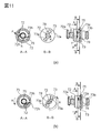
- FIG. 1 is a diagram illustrating an engaging operation of the drive transmission member 1, the first coupling portion 72, and the second coupling portion 73.
- FIG. 11 is a diagram showing the relative positional relationship of the first coupling portion 72 with respect to the second coupling portion 73.
- FIG. 1A shows a state in which the drive transmission portion 1a of the drive transmission member 1 and the driven transmission portion 72a of the first coupling portion 72 are out of phase after the cartridge B is mounted on the apparatus main body A. From here, when the drive transmission member 1 is rotated, the drive transmission member 1 is tilted in the direction of arrow V (FIG. 10) by its own weight due to the chamfered portion 72e of the first coupling portion 72. (Fig. 1 (a) direction of arrow W). At the same time, the drive transmission member 1 is pulled toward the non-drive side (direction of arrow N) due to the twisted shape, and as shown in FIG. Hits.
- the surface 1f of the drive transmission member 1 and the end surface 72f of the first coupling portion 72 are surfaces perpendicular to the rotation axes of the drive transmission member 1 and the first coupling portion 72, respectively.
- the driven transmission portion 72a of the first coupling portion 72 and the drive transmission portion 1a of the drive transmission member 1 are configured to secure the engagement amount in the longitudinal direction required for stable drive transmission.
- the centers of the triangles are aligned by matching the phases of the triangles, and the rotation axes of the drive transmission member 1 and the first coupling portion 72 are aligned by abutting the surfaces perpendicular to the rotation axes. Then, the engagement between the drive transmission member 1 and the first coupling portion 72 is completed.
- the inclination direction of the drive transmission member 1 is the gravity direction, but the inclination direction is not limited to the gravity direction, and as described above, a condition that a part of the chamfered portion 72e is located in the drive transmission portion 1a. If the above conditions are satisfied, engagement is possible even if the inclination direction is any direction. Further, even when the rotation axes of the first coupling portion 72 and the drive transmission member 1 are not parallel and coaxial, the first coupling portion 72 can be engaged with the drive transmission member 1 if the same conditions are satisfied. ..
- the drive transmission member 1 and the first coupling portion 72 are in an engaged state, and drive transmission from the device main body A to the cartridge B is possible. At this time, the drive transmission member 1 and the first coupling portion 72 are both coaxial, but are still in an inclined state with respect to the drum 62. Next, a configuration will be described in which the drive transmission member 1 and the first coupling portion 72 in a state where the rotation axis is inclined with respect to the rotation axis of the drum 62 are in a state where the rotation axes coincide with each other.
- a second coupling portion 73 coaxially and rotatably supported with respect to the first coupling portion 72 is arranged. Between the first coupling portion 72 and the second coupling portion 73, there is a degree of freedom in the rotation direction of 120 ° or more due to the pin insertion hole 73d. Before the start of rotation, the first coupling portion 72 is urged by the second urging member 75 in the direction opposite to the rotation direction at the time of driving (direction of arrow F) with respect to the second coupling portion 73. (See FIG. 11 (a)). Then, when the first coupling portion 72 is rotated by 120 ° or more, the pin 78 moves to the second position (see FIG.
- the pin 78 abuts on the driven transmission portion 73a, so that the driving force of the first coupling portion 72 is transmitted.
- the second coupling portion 73 is in a rotatable state.
- the drive transmission portion 73b of the second coupling portion 73 engages with the driven transmission portion 77a of the lid member 77, and the lid member 77 Becomes rotatable.
- the triangular phases of the drive transmission portion 73b and the driven transmission portion 77a match, and the second coupling portion 73 is pulled toward the non-drive side (direction of arrow N) due to the twisted shape, and the end face 73f It comes into contact with the surface 77f of the lid member 77.
- the end surface 73f of the second coupling portion 73 and the surface 77f of the lid member 77 are surfaces perpendicular to the rotation axis of the second coupling portion 73 and the lid member 77, respectively.
- the rotation axes of the second coupling portion 73 and the lid member 77 coincide with each other. Since the lid member 77 is fixed to the drive-side drum flange 71 and the drive-side drum flange 71 is fixed to the drum 62, the rotation axis of the second coupling portion 73 coincides with that of the drum 62.
- the rotation axes of the drive transmission member 1 and the first coupling portion 72, and the second coupling portion 73 and the drum 62 are aligned with each other. Since the first coupling portion 72 and the second coupling portion 73 are coaxial, as a result, the rotation axes of the drive transmission member 1 and the drum 62 can rotate in the same state.
- the first coupling portion 72 can be engaged with the drive transmission member 1 having an axis inclined with respect to the axis of the drum 62 to be coaxial with the drum 62. .. With this configuration, the drive transmission accuracy from the apparatus main body A to the cartridge B can be improved.
- the coupling member has a first coupling portion 72 and a second coupling portion 73, which are relatively movable. This provides the advantages described below.
- the first coupling portion 72 of the coupling member may not be engaged with the drive transmission member 1. Even in this state, a frictional force is generated between the first coupling portion 72 and the drive transmission member 1, so that the frictional force causes the first coupling portion 72 to rotate slightly before engaging with the drive transmission member 1. There is a risk that it will end up. If the rotation is transmitted from the first coupling portion 72 to the second coupling portion 73 while the first coupling portion 72 is not engaged with the drive transmission member 1, the second coupling portion 73 and the flange member The above-mentioned centering action is unintentionally generated between the (lid member 77).
- the inclination angle of the second coupling portion 73 with respect to the drum 62 becomes smaller.
- the inclination angle of the first coupling portion 72 with respect to the drum 62 also becomes smaller. If the inclination angle of the first coupling portion 72 is reduced before engaging with the drive transmission member 1, the first coupling portion 72 moves away from the drive transmission member 1 and the first coupling There is a risk that the portion 72 cannot engage with the drive transmission member 1.
- the first coupling portion 72 can rotate relative to the second coupling portion 73 within a certain range. Therefore, even if the first coupling portion 72 unintentionally rotates slightly before engaging with the drive transmission member 1, the rotation is not transmitted to the second coupling portion 73.
- the rotation can be transmitted from the first coupling portion 72 to the second coupling portion 73 only after the drive transmission member 1 and the first coupling portion 72 are securely engaged with each other. Therefore, the centering action does not occur unintentionally before the first coupling portion 72 and the drive transmission member 1 are engaged.
- the angle (phase difference) at which the first coupling portion 72 can rotate relative to the second coupling portion 73 from the first position to the second position is set. , 120 degrees or more.
- the phase difference is 120 degrees or less. That is, normally, if the drive transmission member 1 rotates up to 120 degrees, the drive transmission member 1 and the first coupling portion 72 can engage with each other in a triangular shape. Prior to this engagement, even if the first coupling portion 72 is slightly rotated by the above frictional force, its rotation angle is smaller than 120 degrees, and such rotation of the first coupling portion 72 causes the first coupling portion 72 to rotate. 2 The coupling portion 73 does not start rotating.
- the alignment force generated between the second coupling portion 72 and the flange member (77) corrects the inclination of the first coupling portion 72 before the first coupling portion 72 and the drive transmission member 1 engage with each other. Can be suppressed. As a result, it is possible to suppress the occurrence of poor engagement between the drive transmission member 1 and the first coupling portion 72.
- the coupling member of the coupling unit 79 does not necessarily have to be divided into the first coupling portion 72 and the second coupling portion 73 as described above.
- the coupling portion does not have to be divided into the first coupling portion 72 and the second coupling portion 73, and these may be integrated.
- the rotatable angle of the first coupling portion 72 with respect to the second coupling portion 73 is more than 120 degrees. It may be made smaller.
- the drive transmission portion 1a of the drive transmission member 1 and the driven transmission portion 72a of the first coupling portion 72 are engaged with each other, and the drive transmission portion 73b of the second coupling portion 73 and the lid member 77 are driven.
- Each has a characteristic shape to allow engagement of the transmission portions 77a.
- an equilateral triangle has a triangular cross section perpendicular to the axis of rotation, and each apex is chamfered with an arc shape (see FIG. 16).
- the shape is not necessarily limited to this shape.
- the connecting member 2 (FIG. 12) interlocked with the opening / closing door 13 rotates in the process of opening the opening / closing door 13 to an inclined portion (not shown) provided on the drive side plate 15.
- the connecting member 2 moves along the drive side (direction of arrow G).
- the drive transmission member 1 moves to the drive side.
- the drive transmission member 1 moves while rotating in the reverse direction due to the twisted shape of the triangle, and the engagement with the first coupling portion 72 is released.
- the drive transmission member 1 and the first coupling portion 72 are in an inclined state again.
- the drum unit of this embodiment has a coupling member (79) capable of receiving a driving force (rotational force) by engaging and connecting with the driving transmission member 1 (see FIG. 8).
- the coupling member 79 is tiltably supported by flange members (71, 77) fixed to the photoconductor drum 1. That is, the angle formed by the rotation axis of the coupling member 79 and the rotation axis of the photoconductor drum 62 varies.
- the drive transmission member 1 is inclined inside the device main body A (see FIG. 4).
- the coupling member 79 is also tiltable with respect to the photoconductor drum 62 so that it can engage with such a drive transmission member 1 (FIG. 4).
- the cartridge B is provided with an urging member (elastic member, spring) 76 for inclining the coupling member 79 in a predetermined direction that can engage with the drive transmission member 1 (see FIG. 9). .
- the coupling member 79 tilted With the coupling member 79 tilted, the coupling member 79 rotates by receiving a driving force from the drive transmission member 1 (see FIG. 1).
- the centering portion (drive transmission portion 73b, driven transmission portion) provided between the coupling member 79 and the flange member (71, 79) is provided.
- 77a See FIG. 8
- a force is applied to the coupling member 79 to reduce its inclination angle.
- the inclination angle of the coupling member 79 and the drive transmission member 1 connected to the coupling member 79 becomes smaller.
- the driving force can be stably transmitted from the drive transmission member 1 to the photoconductor drum 62 via the coupling member (72, 73) and the flange member (71, 77).
- the drive transmission member 1, the coupling members (72, 73), and the photoconductor drum 62 are arranged substantially coaxially at the time of drive transmission, but they do not necessarily have to be coaxial. .. That is, if the inclination angle of the drive transmission member 1 and the coupling members (72, 73) becomes small, there is an effect of improving the accuracy of the drive transmission.
- the drive transmission member 1 may be tilted or tilted inside the main body of the electrophotographic image forming apparatus depending on the support configuration for supporting the drive transmission member 1.
- the drive transmission configuration including the coupling member described in this embodiment is suitable.
- the drive-side drum flange unit (drive transmission unit) 70 of this embodiment was integrated with the photoconductor drum to form a drum unit. That is, the drive transmission unit 70 was removable from the image forming apparatus main body as a part of the drum unit and the cartridge provided with the drum unit.
- the drive transmission unit 70 does not necessarily have to be integrated with the photoconductor drum, and the drive transmission unit 70 does not necessarily have to be a part of the drum unit or a part of the cartridge.
- the drive transmission unit 70 may be a unit (detachable unit, attachment) or a part thereof that can be attached to the main body of the electrophotographic image forming apparatus by the user. That is, the drive transmission unit 70 may be one that can receive a driving force in connection with the drive transmission member 1 when attached to the main body of the electrophotographic image forming apparatus.
- the object to which the drive transmission unit 70 transmits the driving force may be not the photoconductor drum 62 but another member, for example, the developing roller 23. Further, the drive transmission unit 70 does not have to be directly connected to an object (photoreceptor drum in this embodiment) for transmitting the driving force.
- the cartridge has a drive transmission unit 70 and a photoconductor drum 62, while the cartridges are arranged apart from each other and are indirectly connected to each other via a gear or the like.
- the coupling member of the drive transmission unit 70 can be drive-transmitted, that is, operatively connected to the photoconductor drum 62.
- the drive transmission unit 70 may be separable from the drum unit or the cartridge.
- the user first attaches the drive transmission unit 70 to the image forming apparatus main body. After that, the user may attach the cartridge or the drum unit to the image forming apparatus main body and connect them to the drive transmission unit 70.
- one of the drive transmission portion 73b and the driven transmission portion 77a which are the centering portions, has a convex shape (projection, convex portion), and the other has a concave shape (dent, concave portion) that can engage with the protrusion. ).
- the drive transmission unit 73b rotates with respect to the driven transmission unit 77a, one of the convex shape and the concave shape engages with the other while rotating. Since at least one of the convex shape and the concave shape is twisted, when one of the convex shape and the concave shape is engaged with the other while rotating, the axes of the convex shape and the concave shape are aligned by the action of this twist.
- the inclination angle of the flange members (71, 77) with respect to the coupling member 79 becomes small, and the inclination angle of the coupling member 79 with respect to the drum 62 also becomes small.
- the rotation axes of the coupling member 79 and the drum 62 substantially coincide with each other.
- the drive transmission portion 73b has a convex shape
- the driven transmission portion 77a has a concave shape.
- twists are added to both the convex and concave shapes.
- the cross-sectional shapes of the drive transmission unit 73b and the driven transmission unit 77a are substantially triangular. That is, the cross section has a shape in which the vicinity of the apex of the equilateral triangle is an arc. However, the cross section may have a different shape. ⁇ Example 2>
- the drive transmission member 1 is configured to be tiltable (tiltable).
- the attachment / detachment operation of the cartridge B and the engagement between the drive transmission member 1 and the first coupling portion 82 are the same as those in the first embodiment, and thus the description thereof will be omitted.
- the second embodiment is a modification of the configuration of the drive-side drum flange unit 80 for changing the state in which the rotation axis of the first coupling portion 82 and the rotation axis of the drum 62 are displaced to a coaxial state.
- FIG. 13 is a diagram illustrating a method of assembling the coupling unit 89 and the drive side drum flange unit 80.
- FIG. 14 is a diagram illustrating an engaging operation of the drive transmission member 1, the first coupling portion 82, and the second coupling portion 83.
- FIG. 15 is a diagram showing the relative positional relationship of the first coupling portion 82 with respect to the second coupling portion 83.
- the coupling unit 89 is composed of a first coupling portion 82, a second coupling portion 83, a second urging member 85, and a pin 88.
- the drive-side drum flange unit 80 is composed of a drive-side drum flange 81, a coupling unit 89, a first urging member 84, and a lid member 87.
- the drum unit in this embodiment corresponds to the drive-side drum flange unit 70 (see FIG. 8E) of the drum unit in Example 1 replaced with the drive-side drum flange unit. That is, the drum unit in this embodiment includes a driving side drum flange unit 80, a photoconductor drum 62, and a driven side drum flange 63 (see FIG. 8E).
- the drive-side drum flange 81 and the lid member 87 may be collectively referred to as a flange member, or the lid member 87 may be regarded as a part of the drive-side drum flange 81.
- the first coupling portion 82 has a driven transmission portion 82a that engages with the drive transmission member 1 and receives a driving force, and a shaft portion 82k, and is inclined by a third urging member 86 (not shown).
- the second coupling portion 83 is engaged with a hole portion 83k into which a shaft portion 82k is inserted and coaxially and rotatably supported with the first coupling portion 82, and a driven transmission portion 81a of the driving side drum flange 81.
- the first urging member (first elastic member, first spring) 84 urges the first coupling portion 82 and the second coupling portion 83 toward the drive side in the longitudinal direction (direction of arrow G in FIG. 14). ..
- the second urging member 85 urges the first coupling portion 82 in the rotational direction with respect to the second coupling portion 83, as in the first embodiment.
- first coupling portion 82 and the second coupling portion 83 are provided with inclined portions 82 g and 83 g that come into contact with each other, and the first coupling portion 82 rotates to enable movement in the longitudinal direction. ..
- first coupling portion 82 is not driven and transmitted, the first coupling portion 82 is urged in the rotational direction by the second urging member 85, and the pin 88 is inserted into the pin insertion hole 83d of the second coupling portion 83. It is located at the first position (see FIG. 15A) in contact with the end face.
- the pin insertion hole 83d of the second coupling portion 83 has a degree of freedom of 120 ° or more in the rotation direction.
- the pin 88 reaches the second position where the driven transmission portion 83a abuts (see FIG. 15B). Then, the driving force of the first coupling portion 82 is transmitted, and the second coupling portion 83 becomes rotatable.
- the second coupling portion 83 moves to the non-driving side (direction of arrow N) along the inclined portions 82 g and 83 g, and is spherically shaped as the regulated portion 83c (second regulated portion). The portion) comes into contact with the conical regulating portion 87c (second regulating portion) of the lid member 87.
- the second coupling portion 83 is provided with a drive transmission portion 83b, the drive side drum flange 81 is provided with a driven transmission portion 81a corresponding to the drive transmission portion 83b, and the second coupling portion 83 is provided on the drive side drum flange 81. On the other hand, it can move relatively in the longitudinal direction. When the second coupling portion 83 rotates, the drive-side drum flange 81 and the drum 62 can rotate.
- the first coupling portion 82, the second coupling portion 83, and the pin 88 are collectively referred to as a coupling member.
- the coupling members (82, 83, 88) are configured to transmit a driving force (rotational force) to the photoconductor drum 62 via the flange members (81, 87).
- the drive transmission member is tilted and is not engaged with the first coupling portion 82.
- the spherically-shaped regulated portion 82c first regulating portion
- the conical-shaped regulating portion 81c first regulation of the drive-side drum flange 81 is used. It is in contact with the part).
- FIG. 14B when the drive transmission member 1 rotates, the triangular phases of the drive transmission unit 1a and the driven transmission unit 82a coincide with each other, and the drive transmission member 1a has the same triangular phase as in the first embodiment.
- the surface 1f of 1 abuts on the end surface 82f of the first coupling portion 82 and rotates. Therefore, the first coupling portion 82 rotates in a state where the rotation shaft of the drive transmission member 1 coincides with the rotation shaft of the first coupling portion 82. Then, the inclined portion 83 g of the second coupling portion 83 moves along the inclined portion 82 g to the non-driving side (direction of arrow N) in the longitudinal direction. At this time, while moving along the inclined portion 82g, there is a degree of freedom in the rotation direction of 120 ° or more between the first coupling portion 82 and the second coupling portion 83 due to the hole portion 83d, so that the second coupling portion 82 has a second degree of freedom.
- the coupling portion 83 does not rotate.
- the second coupling portion 83 moves to the second position on the non-driving side along the inclined portion 82 g (see FIG. 15 (b)) as shown in FIG. 14 (c).
- the spherically-shaped regulated portion 83c abuts on the conical-shaped regulating portion 87c of the lid member 87.
- the second coupling portion 83 rotates, and the drive transmission portion 83b of the second coupling portion 83 comes into contact with the driven transmission portion 81a of the drive side drum flange 81 to rotate the drum 62.
- the first coupling portion 82 abuts on the regulation portion 81c of the drive-side drum flange 81
- the second coupling portion 83 abuts on the regulation portion 87c of the lid member 87. Therefore, as shown in FIG. 14C, the positions of the centers Q1 and Q2 of the regulated portion 82c of the first coupling portion 82 and the regulated portion 83c of the second coupling portion 83 are determined.
- the conical central axis of the regulation portion 81c of the drive-side drum flange 81 and the conical central axis of the regulation portion 87c of the lid member 87 are both set to be coaxial with the rotation axis of the drum 62. ..
- the centers Q1 and Q2 are set so as to be located on the rotation axes of the first coupling portion 82 and the second coupling portion 83, respectively. Therefore, since the first coupling portion 82 and the second coupling portion 83 are coaxial, the straight line connecting the centers Q1 and Q2, that is, the rotation axis of the first coupling portion 82 and the second coupling portion 83 will be any longer. Also coincides with the rotation axis of the drum 62.
- the first coupling portion 82 in the present embodiment is a drive transmission member 1 having a configuration in which the rotation shaft before engagement is inclined with respect to the first coupling portion 82. Can also be engaged. Further, even when the rotation axes of the first coupling portion 82 and the drive transmission member 1 before engagement are parallel and not coaxial, the first coupling portion 82 of the present embodiment engages with the drive transmission member 1. Can be done.
- the regulated portion 81c of the drive-side drum flange 81 and the regulated portion 82c of the first coupling portion 82 adopt a concave shape having a conical surface and a convex shape having a spherical surface, respectively.
- the regulated portion 87c of the lid member 87 and the regulated portion 83c of the second coupling portion 83 adopt a concave shape having a conical surface and a convex shape having a spherical surface, respectively.
- the relationship between the concave shape having a conical surface and the convex shape having a spherical surface may be reversed.
- the regulated portions 81c and 87c and the regulated portions 82c and 83c are the centering portions in the second embodiment.
- the first coupling portion 82 is engaged with the drive transmission member 1 having an axis inclined with respect to the axis of the drum 62, and the drum 62. Can be coaxial with. With this configuration, the drive transmission accuracy from the apparatus main body A to the cartridge B can be improved.
- the first coupling portion 82 and the second coupling portion 83 are configured to be relatively movable. As shown in FIG. 14B, the first coupling portion 82 rotates by engaging with the drive transmission member 1. Then, one of the first coupling portion 82 and the second coupling member 83 moves in the axial direction with respect to the other. That is, the second coupling portion 83 moves with respect to the first coupling portion 82 in the axial direction of the drum (direction of arrow N in FIG. 14C).
- the regulated portion 82c provided on the first coupling portion 82 comes into contact with (presses) the regulated portion 81c provided on the flange member (driving side drum flange 81). Further, the regulated portion 83c provided on the second coupling portion 83 comes into contact with (presses) the regulated portion 87c provided on the flange member (lid member 77).
- the coupling members (first coupling portion 82, second coupling portion 83) are centered. That is, the inclination angle of the coupling members (82, 83) with respect to the photoconductor drum 62 becomes small.
- the drive transmission member 1, the coupling members (82, 83), and the photoconductor drum 62 are arranged substantially coaxially, and the accuracy of these drive transmissions is improved.
- the first coupling portion 82 and the second coupling portion 83 have inclined portions 82 g and 83 g (see FIG. 13 (a)) as cam mechanisms. Therefore, when the first coupling portion 82 rotates with respect to the second coupling portion 83, the relative positions of the first coupling portion 82 and the second coupling portion 83 are in the axial direction along the inclined portions 82g and 83g. It is configured to change in.
- one of the regulated portion 82c provided on the first coupling portion 82 and the regulated portion 81c provided on the flange member (driving side drum flange 81) has a spherical convex shape, and the other is spherical or spherical. It has a conical concave shape.
- one of the regulated portion 83c provided on the second coupling portion 83 and the regulated portion 87c provided on the flange member (lid member 77) has a spherical convex shape, and the other has a spherical or conical shape. It has a concave shape.
- the action of centering occurs by engaging the concave shape and the convex shape as described above.
- a drum unit, a drive transmission unit, a cartridge, and an electrophotographic image forming apparatus suitable for them, which can be used for an image forming apparatus such as an electrophotographic image forming apparatus, are provided.
Landscapes
- Physics & Mathematics (AREA)
- General Physics & Mathematics (AREA)
- Engineering & Computer Science (AREA)
- Computer Vision & Pattern Recognition (AREA)
- Electrophotography Configuration And Component (AREA)
- Discharging, Photosensitive Material Shape In Electrophotography (AREA)
Priority Applications (19)
| Application Number | Priority Date | Filing Date | Title |
|---|---|---|---|
| KR1020227000845A KR102749362B1 (ko) | 2019-06-12 | 2020-06-09 | 드럼 유닛, 구동 전달 유닛, 카트리지 및 전자사진 화상 형성 장치 |
| CN202080042378.1A CN113966491B (zh) | 2019-06-12 | 2020-06-09 | 鼓单元、驱动传递单元、盒及电子照相成像设备 |
| MYPI2021007258A MY210326A (en) | 2019-06-12 | 2020-06-09 | Drum unit, drive transmission unit, cartridge and electrophotographic image forming apparatus |
| KR1020257034387A KR20250154544A (ko) | 2019-06-12 | 2020-06-09 | 드럼 유닛 및 카트리지 |
| PH1/2021/553087A PH12021553087A1 (en) | 2019-06-12 | 2020-06-09 | Drum unit, drive transmission unit, cartridge and electrophotographic image forming apparatus |
| CN202510221589.6A CN119937266A (zh) | 2019-06-12 | 2020-06-09 | 鼓单元、驱动传递单元、盒及电子照相成像设备 |
| AU2020290276A AU2020290276B2 (en) | 2019-06-12 | 2020-06-09 | Drum unit, drive transmission unit, cartridge and electrophotographic image forming apparatus |
| CA3142869A CA3142869C (en) | 2019-06-12 | 2020-06-09 | DRUM UNIT, DRIVE TRANSMISSION UNIT, CARTRIDGE AND ELECTRONIC PHOTOGRAPHIC IMAGE FORMING DEVICE |
| EP20823625.7A EP3985443A4 (en) | 2019-06-12 | 2020-06-09 | DRUM UNIT, DRIVE TRANSMISSION UNIT, CASSETTE AND ELECTRONIC PHOTOGRAPHIC FORMING DEVICE |
| BR112021023674A BR112021023674A2 (pt) | 2019-06-12 | 2020-06-09 | Unidade de tambor, unidade de transmissão de acionamento, cartucho e aparelho de formação de imagem eletrofotográfica |
| MX2021015203A MX2021015203A (es) | 2019-06-12 | 2020-06-09 | Unidad de tambor, unidad de transmision de accionamiento, cartucho y aparato de formacion de imagenes electrofotograficas. |
| KR1020247042756A KR102875460B1 (ko) | 2019-06-12 | 2020-06-09 | 드럼 유닛 및 카트리지 |
| SG11202113334PA SG11202113334PA (en) | 2019-06-12 | 2020-06-09 | Drum unit, drive transmission unit, cartridge and electrophotographic image forming apparatus |
| US17/532,021 US12025941B2 (en) | 2019-06-12 | 2021-11-22 | Drum unit, drive transmission unit, cartridge and electrophotographic image forming apparatus |
| CONC2021/0017384A CO2021017384A2 (es) | 2019-06-12 | 2021-12-17 | Unidad de tambor, unidad de transmisión de accionamiento, cartucho y aparato de formación de imagen electrográfica |
| US18/381,284 US12287600B2 (en) | 2019-06-12 | 2023-10-18 | Drum unit, drive transmission unit, cartridge and electrophotographic image forming apparatus |
| AU2023266346A AU2023266346B2 (en) | 2019-06-12 | 2023-11-16 | Drum unit, drive transmission unit, cartridge and electrophotographic image forming apparatus |
| US19/034,783 US20250164918A1 (en) | 2019-06-12 | 2025-01-23 | Drum unit, drive transmission unit, cartridge and electrophotographic image forming apparatus |
| AU2025220871A AU2025220871A1 (en) | 2019-06-12 | 2025-08-25 | Drum unit, drive transmission unit, cartridge and electrophotographic image forming apparatus |
Applications Claiming Priority (2)
| Application Number | Priority Date | Filing Date | Title |
|---|---|---|---|
| JP2019-109671 | 2019-06-12 | ||
| JP2019109671 | 2019-06-12 |
Related Child Applications (1)
| Application Number | Title | Priority Date | Filing Date |
|---|---|---|---|
| US17/532,021 Continuation US12025941B2 (en) | 2019-06-12 | 2021-11-22 | Drum unit, drive transmission unit, cartridge and electrophotographic image forming apparatus |
Publications (1)
| Publication Number | Publication Date |
|---|---|
| WO2020251052A1 true WO2020251052A1 (ja) | 2020-12-17 |
Family
ID=73780961
Family Applications (1)
| Application Number | Title | Priority Date | Filing Date |
|---|---|---|---|
| PCT/JP2020/023319 Ceased WO2020251052A1 (ja) | 2019-06-12 | 2020-06-09 | ドラムユニット、駆動伝達ユニット、カートリッジおよび電子写真画像形成装置 |
Country Status (17)
| Country | Link |
|---|---|
| US (3) | US12025941B2 (https=) |
| EP (1) | EP3985443A4 (https=) |
| JP (2) | JP7614746B2 (https=) |
| KR (3) | KR20250154544A (https=) |
| CN (2) | CN113966491B (https=) |
| AU (3) | AU2020290276B2 (https=) |
| BR (1) | BR112021023674A2 (https=) |
| CA (1) | CA3142869C (https=) |
| CL (1) | CL2021003282A1 (https=) |
| CO (1) | CO2021017384A2 (https=) |
| MA (1) | MA56216A (https=) |
| MX (1) | MX2021015203A (https=) |
| MY (1) | MY210326A (https=) |
| PH (1) | PH12021553087A1 (https=) |
| SG (1) | SG11202113334PA (https=) |
| TW (2) | TWI800736B (https=) |
| WO (1) | WO2020251052A1 (https=) |
Families Citing this family (4)
| Publication number | Priority date | Publication date | Assignee | Title |
|---|---|---|---|---|
| CN120044773A (zh) | 2019-03-18 | 2025-05-27 | 佳能株式会社 | 电子照相成像设备、盒和鼓单元 |
| MX2021015203A (es) * | 2019-06-12 | 2022-01-18 | Canon Kk | Unidad de tambor, unidad de transmision de accionamiento, cartucho y aparato de formacion de imagenes electrofotograficas. |
| JP7822723B2 (ja) | 2020-08-31 | 2026-03-03 | キヤノン株式会社 | 感光体ユニット、カートリッジ、電子写真画像形成装置 |
| JP2024002824A (ja) | 2022-06-24 | 2024-01-11 | キヤノン株式会社 | カートリッジ及び画像形成装置 |
Citations (10)
| Publication number | Priority date | Publication date | Assignee | Title |
|---|---|---|---|---|
| JP2006163232A (ja) * | 2004-12-10 | 2006-06-22 | Ntn Corp | 画像形成装置 |
| JP2009300516A (ja) * | 2008-06-10 | 2009-12-24 | Canon Inc | カートリッジ、及び、前記カートリッジを用いた電子写真画像形成装置 |
| JP2013122616A (ja) * | 2006-12-22 | 2013-06-20 | Canon Inc | プロセスカートリッジ、電子写真画像形成装置、及び、電子写真感光体ドラムユニット |
| JP2013195961A (ja) * | 2012-03-22 | 2013-09-30 | Fuji Xerox Co Ltd | 被回転体の駆動構造及び画像形成装置 |
| JP2014191025A (ja) * | 2013-03-26 | 2014-10-06 | Mitsubishi Chemicals Corp | 軸受部材、端部部材、感光体ドラムユニット、及びプロセスカートリッジ |
| JP2016102986A (ja) * | 2014-11-28 | 2016-06-02 | キヤノン株式会社 | カートリッジ及び画像形成装置 |
| US20170075300A1 (en) * | 2014-05-06 | 2017-03-16 | Apex Technology Co.,Ltd. | Processing cartridge and driving assembly thereof |
| JP2017107066A (ja) * | 2015-12-09 | 2017-06-15 | 株式会社リコー | 駆動伝達装置および画像形成装置 |
| JP2017223802A (ja) | 2016-06-14 | 2017-12-21 | キヤノン株式会社 | 電子写真画像形成装置 |
| JP2019109671A (ja) | 2017-12-18 | 2019-07-04 | 株式会社オービック | 受注登録装置、受注登録方法、および、受注登録プログラム |
Family Cites Families (40)
| Publication number | Priority date | Publication date | Assignee | Title |
|---|---|---|---|---|
| US6990301B2 (en) | 2001-02-19 | 2006-01-24 | Canon Kabushiki Kaisha | Sealing member, toner accommodating container and image forming apparatus |
| JP2003255804A (ja) | 2001-12-07 | 2003-09-10 | Canon Inc | プロセスカートリッジの再生産方法および現像装置の再生産方法 |
| JP2003241606A (ja) | 2002-02-20 | 2003-08-29 | Canon Inc | プロセスカートリッジ及びクリーニング装置 |
| JP3809402B2 (ja) | 2002-05-17 | 2006-08-16 | キヤノン株式会社 | プロセスカートリッジ、及び、電子写真画像形成装置 |
| JP3970161B2 (ja) | 2002-11-08 | 2007-09-05 | キヤノン株式会社 | プロセスカートリッジの再生産方法 |
| JP3548564B2 (ja) | 2002-11-08 | 2004-07-28 | キヤノン株式会社 | 現像ローラー組立方法 |
| JP2004205950A (ja) | 2002-12-26 | 2004-07-22 | Canon Inc | クリーニング装置、プロセスカートリッジおよび画像形成装置 |
| US7228090B2 (en) | 2004-02-26 | 2007-06-05 | Konica Minolta Business Technologies, Inc. | Image forming apparatus with a removable process unit capable of securing rotation transmission accuracy without stressing a holding portion despite shaft misalignment |
| JP2005242255A (ja) | 2004-02-27 | 2005-09-08 | Canon Inc | プロセスカートリッジ、現像カートリッジ、及び把持部材部品 |
| JP4948382B2 (ja) | 2006-12-22 | 2012-06-06 | キヤノン株式会社 | 感光ドラム取り付け用カップリング部材 |
| JP5127584B2 (ja) | 2008-06-20 | 2013-01-23 | キヤノン株式会社 | ドラムユニット、及び、電子写真画像形成装置 |
| JP4803267B2 (ja) * | 2009-02-17 | 2011-10-26 | 富士ゼロックス株式会社 | 画像形成装置 |
| CN103853012B (zh) * | 2009-03-30 | 2017-10-24 | 佳能株式会社 | 显影剂供给容器和显影剂供给系统 |
| CA2892185C (en) * | 2009-03-30 | 2017-12-05 | Canon Kabushiki Kaisha | Developer supply container and developer supplying system |
| JP5704911B2 (ja) * | 2009-12-16 | 2015-04-22 | キヤノン株式会社 | カートリッジ、及び、電子写真画像形成装置 |
| JP2012003243A (ja) | 2010-05-19 | 2012-01-05 | Canon Inc | プロセスカートリッジ及び電子写真画像形成装置 |
| JP5868079B2 (ja) | 2011-09-05 | 2016-02-24 | キヤノン株式会社 | カートリッジおよび画像形成装置 |
| JP5847507B2 (ja) | 2011-09-14 | 2016-01-20 | キヤノン株式会社 | カートリッジ及び画像形成装置 |
| TWI640849B (zh) | 2011-12-06 | 2018-11-11 | 日商佳能股份有限公司 | 旋轉力傳達單元 |
| US8867970B2 (en) | 2011-12-30 | 2014-10-21 | Lexmark International, Inc. | Toner cartridges having positional control features |
| JP6140962B2 (ja) | 2012-09-27 | 2017-06-07 | キヤノン株式会社 | カートリッジ及びプロセスカートリッジ及び画像形成装置 |
| JP6053428B2 (ja) | 2012-09-27 | 2016-12-27 | キヤノン株式会社 | 現像剤収容容器、現像カートリッジ、プロセスカートリッジ及び画像形成装置 |
| JP5975823B2 (ja) | 2012-09-28 | 2016-08-23 | キヤノン株式会社 | カートリッジ及び画像形成装置 |
| JP6245932B2 (ja) | 2012-11-06 | 2017-12-13 | キヤノン株式会社 | カートリッジ、現像カートリッジ、プロセスカートリッジ及び画像形成装置 |
| JP6370039B2 (ja) | 2013-01-31 | 2018-08-08 | キヤノン株式会社 | 収納容器、現像装置、プロセスカートリッジ及び画像形成装置 |
| JP6289172B2 (ja) | 2013-05-23 | 2018-03-07 | キヤノン株式会社 | 現像剤容器、現像カートリッジ、プロセスカートリッジ及び画像形成装置 |
| JP6112974B2 (ja) | 2013-05-31 | 2017-04-12 | キヤノン株式会社 | 現像剤容器、現像カートリッジ、プロセスカートリッジ及び画像形成装置 |
| JP6173069B2 (ja) | 2013-06-27 | 2017-08-02 | キヤノン株式会社 | 現像剤容器、現像カートリッジ、プロセスカートリッジ及び画像形成装置 |
| JP6415198B2 (ja) * | 2013-09-12 | 2018-10-31 | キヤノン株式会社 | カートリッジ |
| US9740163B2 (en) * | 2013-09-29 | 2017-08-22 | Ninestar Corporation | Rotational force driving assembly process cartridge |
| JP2016148783A (ja) | 2015-02-12 | 2016-08-18 | 三菱化学株式会社 | 軸部材、端部部材、感光体ドラムユニット、現像ローラユニット、プロセスカートリッジ |
| KR102859791B1 (ko) | 2015-02-27 | 2025-09-12 | 캐논 가부시끼가이샤 | 드럼 유닛, 카트리지 및 전자 사진 형성 장치 |
| US10082954B2 (en) | 2015-09-04 | 2018-09-25 | International Business Machines Corporation | Challenge generation for verifying users of computing devices |
| BR112018074598B1 (pt) | 2016-06-14 | 2024-01-16 | Canon Kabushiki Kaisha | Cartucho de processo e aparelho de formação de imagem eletrofotográfica |
| JP6207702B2 (ja) * | 2016-09-26 | 2017-10-04 | キヤノン株式会社 | プロセスカートリッジ |
| JP6699625B2 (ja) | 2017-05-31 | 2020-05-27 | 京セラドキュメントソリューションズ株式会社 | ジョイント機構及びこれを備えた画像形成装置 |
| JP7058992B2 (ja) | 2017-12-13 | 2022-04-25 | キヤノン株式会社 | 画像形成装置およびカートリッジ |
| CN116184786B (zh) | 2017-12-13 | 2026-01-27 | 佳能株式会社 | 盒与图像形成装置 |
| US10627780B2 (en) | 2018-01-23 | 2020-04-21 | Canon Kabushiki Kaisha | Cartridge and image forming apparatus |
| MX2021015203A (es) * | 2019-06-12 | 2022-01-18 | Canon Kk | Unidad de tambor, unidad de transmision de accionamiento, cartucho y aparato de formacion de imagenes electrofotograficas. |
-
2020
- 2020-06-09 MX MX2021015203A patent/MX2021015203A/es unknown
- 2020-06-09 EP EP20823625.7A patent/EP3985443A4/en active Pending
- 2020-06-09 CN CN202080042378.1A patent/CN113966491B/zh active Active
- 2020-06-09 CA CA3142869A patent/CA3142869C/en active Active
- 2020-06-09 CN CN202510221589.6A patent/CN119937266A/zh active Pending
- 2020-06-09 AU AU2020290276A patent/AU2020290276B2/en active Active
- 2020-06-09 SG SG11202113334PA patent/SG11202113334PA/en unknown
- 2020-06-09 KR KR1020257034387A patent/KR20250154544A/ko active Pending
- 2020-06-09 KR KR1020227000845A patent/KR102749362B1/ko active Active
- 2020-06-09 WO PCT/JP2020/023319 patent/WO2020251052A1/ja not_active Ceased
- 2020-06-09 KR KR1020247042756A patent/KR102875460B1/ko active Active
- 2020-06-09 PH PH1/2021/553087A patent/PH12021553087A1/en unknown
- 2020-06-09 MY MYPI2021007258A patent/MY210326A/en unknown
- 2020-06-09 MA MA056216A patent/MA56216A/fr unknown
- 2020-06-09 BR BR112021023674A patent/BR112021023674A2/pt unknown
- 2020-06-10 JP JP2020101128A patent/JP7614746B2/ja active Active
- 2020-06-12 TW TW109119824A patent/TWI800736B/zh active
- 2020-06-12 TW TW112111050A patent/TWI826294B/zh active
-
2021
- 2021-11-22 US US17/532,021 patent/US12025941B2/en active Active
- 2021-12-09 CL CL2021003282A patent/CL2021003282A1/es unknown
- 2021-12-17 CO CONC2021/0017384A patent/CO2021017384A2/es unknown
-
2023
- 2023-10-18 US US18/381,284 patent/US12287600B2/en active Active
- 2023-11-16 AU AU2023266346A patent/AU2023266346B2/en active Active
-
2024
- 2024-12-26 JP JP2024230058A patent/JP7841070B2/ja active Active
-
2025
- 2025-01-23 US US19/034,783 patent/US20250164918A1/en active Pending
- 2025-08-25 AU AU2025220871A patent/AU2025220871A1/en active Pending
Patent Citations (10)
| Publication number | Priority date | Publication date | Assignee | Title |
|---|---|---|---|---|
| JP2006163232A (ja) * | 2004-12-10 | 2006-06-22 | Ntn Corp | 画像形成装置 |
| JP2013122616A (ja) * | 2006-12-22 | 2013-06-20 | Canon Inc | プロセスカートリッジ、電子写真画像形成装置、及び、電子写真感光体ドラムユニット |
| JP2009300516A (ja) * | 2008-06-10 | 2009-12-24 | Canon Inc | カートリッジ、及び、前記カートリッジを用いた電子写真画像形成装置 |
| JP2013195961A (ja) * | 2012-03-22 | 2013-09-30 | Fuji Xerox Co Ltd | 被回転体の駆動構造及び画像形成装置 |
| JP2014191025A (ja) * | 2013-03-26 | 2014-10-06 | Mitsubishi Chemicals Corp | 軸受部材、端部部材、感光体ドラムユニット、及びプロセスカートリッジ |
| US20170075300A1 (en) * | 2014-05-06 | 2017-03-16 | Apex Technology Co.,Ltd. | Processing cartridge and driving assembly thereof |
| JP2016102986A (ja) * | 2014-11-28 | 2016-06-02 | キヤノン株式会社 | カートリッジ及び画像形成装置 |
| JP2017107066A (ja) * | 2015-12-09 | 2017-06-15 | 株式会社リコー | 駆動伝達装置および画像形成装置 |
| JP2017223802A (ja) | 2016-06-14 | 2017-12-21 | キヤノン株式会社 | 電子写真画像形成装置 |
| JP2019109671A (ja) | 2017-12-18 | 2019-07-04 | 株式会社オービック | 受注登録装置、受注登録方法、および、受注登録プログラム |
Also Published As
Similar Documents
| Publication | Publication Date | Title |
|---|---|---|
| JP7841070B2 (ja) | ドラムユニット、駆動伝達ユニット、カートリッジおよび電子写真画像形成装置 | |
| US6459869B2 (en) | Process cartridge and image forming apparatus | |
| US10635047B2 (en) | Cartridge and image forming apparatus using the cartridge | |
| JP2002304106A (ja) | プロセスカートリッジ及び電子写真感光体ドラム及び電子写真画像形成装置及びカラー電子写真画像形成装置 | |
| US20050117934A1 (en) | Process cartridge, mounting method of electrophotographic photosensitive drum and replacing method of the photosensitive drum | |
| JP2004086182A (ja) | プロセスカートリッジおよび電子写真画像形成装置 | |
| US7310489B2 (en) | Process cartridge including first and second portions to be positioned and first and second portions to be supported and image forming apparatus detachably mounting such process cartridge | |
| HK40060456A (en) | Drum unit, drive transmission unit, cartridge, and electronic photo image forming device | |
| KR20170044013A (ko) | 전자 사진 감광 드럼 유닛, 카트리지 및 플랜지 부재 | |
| HK40120180A (zh) | 鼓单元、驱动传递单元、盒及电子照相成像设备 | |
| HK40060456B (zh) | 鼓单元、驱动传递单元、盒及电子照相成像设备 | |
| JP2007047298A (ja) | プロセスカートリッジに用いられる離間部材の位相合わせ組立方法 | |
| HK1164463A1 (en) | Electrophotographic image forming apparatus, developing apparatus, and coupling member | |
| HK1164463B (en) | Electrophotographic image forming apparatus, developing apparatus, and coupling member | |
| HK1164467B (en) | Electrophotographic image forming apparatus, developing apparatus, and coupling member |
Legal Events
| Date | Code | Title | Description |
|---|---|---|---|
| 121 | Ep: the epo has been informed by wipo that ep was designated in this application |
Ref document number: 20823625 Country of ref document: EP Kind code of ref document: A1 |
|
| ENP | Entry into the national phase |
Ref document number: 3142869 Country of ref document: CA |
|
| REG | Reference to national code |
Ref country code: BR Ref legal event code: B01A Ref document number: 112021023674 Country of ref document: BR |
|
| NENP | Non-entry into the national phase |
Ref country code: DE |
|
| WWE | Wipo information: entry into national phase |
Ref document number: NC2021/0017384 Country of ref document: CO |
|
| ENP | Entry into the national phase |
Ref document number: 112021023674 Country of ref document: BR Kind code of ref document: A2 Effective date: 20211124 |
|
| ENP | Entry into the national phase |
Ref document number: 20227000845 Country of ref document: KR Kind code of ref document: A |
|
| ENP | Entry into the national phase |
Ref document number: 2020823625 Country of ref document: EP Effective date: 20220112 |
|
| WWP | Wipo information: published in national office |
Ref document number: NC2021/0017384 Country of ref document: CO |
|
| ENP | Entry into the national phase |
Ref document number: 2020290276 Country of ref document: AU Date of ref document: 20200609 Kind code of ref document: A |
|
| WWG | Wipo information: grant in national office |
Ref document number: 202080042378.1 Country of ref document: CN |
|
| WWG | Wipo information: grant in national office |
Ref document number: NC2021/0017384 Country of ref document: CO |
|
| WWG | Wipo information: grant in national office |
Ref document number: MX/A/2021/015203 Country of ref document: MX |
|
| WWD | Wipo information: divisional of initial pct application |
Ref document number: 1020257034387 Country of ref document: KR |
|
| WWP | Wipo information: published in national office |
Ref document number: 1020257034387 Country of ref document: KR |