WO2020250499A1 - 切削工具 - Google Patents
切削工具 Download PDFInfo
- Publication number
- WO2020250499A1 WO2020250499A1 PCT/JP2020/008122 JP2020008122W WO2020250499A1 WO 2020250499 A1 WO2020250499 A1 WO 2020250499A1 JP 2020008122 W JP2020008122 W JP 2020008122W WO 2020250499 A1 WO2020250499 A1 WO 2020250499A1
- Authority
- WO
- WIPO (PCT)
- Prior art keywords
- axial direction
- cutting tool
- cross
- binderless
- boron nitride
- Prior art date
- Legal status (The legal status is an assumption and is not a legal conclusion. Google has not performed a legal analysis and makes no representation as to the accuracy of the status listed.)
- Ceased
Links
Images


Classifications
-
- B—PERFORMING OPERATIONS; TRANSPORTING
- B23—MACHINE TOOLS; METAL-WORKING NOT OTHERWISE PROVIDED FOR
- B23C—MILLING
- B23C5/00—Milling-cutters
- B23C5/02—Milling-cutters characterised by the shape of the cutter
- B23C5/10—Shank-type cutters, i.e. with an integral shaft
- B23C5/1009—Ball nose end mills
-
- B—PERFORMING OPERATIONS; TRANSPORTING
- B23—MACHINE TOOLS; METAL-WORKING NOT OTHERWISE PROVIDED FOR
- B23B—TURNING; BORING
- B23B51/00—Tools for drilling machines
- B23B51/02—Twist drills
-
- B—PERFORMING OPERATIONS; TRANSPORTING
- B23—MACHINE TOOLS; METAL-WORKING NOT OTHERWISE PROVIDED FOR
- B23C—MILLING
- B23C5/00—Milling-cutters
- B23C5/02—Milling-cutters characterised by the shape of the cutter
- B23C5/10—Shank-type cutters, i.e. with an integral shaft
-
- B—PERFORMING OPERATIONS; TRANSPORTING
- B23—MACHINE TOOLS; METAL-WORKING NOT OTHERWISE PROVIDED FOR
- B23B—TURNING; BORING
- B23B2222/00—Materials of tools or workpieces composed of metals, alloys or metal matrices
- B23B2222/28—Details of hard metal, i.e. cemented carbide
-
- B—PERFORMING OPERATIONS; TRANSPORTING
- B23—MACHINE TOOLS; METAL-WORKING NOT OTHERWISE PROVIDED FOR
- B23B—TURNING; BORING
- B23B2226/00—Materials of tools or workpieces not comprising a metal
- B23B2226/12—Boron nitride
- B23B2226/125—Boron nitride cubic [CBN]
-
- B—PERFORMING OPERATIONS; TRANSPORTING
- B23—MACHINE TOOLS; METAL-WORKING NOT OTHERWISE PROVIDED FOR
- B23B—TURNING; BORING
- B23B2226/00—Materials of tools or workpieces not comprising a metal
- B23B2226/31—Diamond
-
- B—PERFORMING OPERATIONS; TRANSPORTING
- B23—MACHINE TOOLS; METAL-WORKING NOT OTHERWISE PROVIDED FOR
- B23B—TURNING; BORING
- B23B2226/00—Materials of tools or workpieces not comprising a metal
- B23B2226/31—Diamond
- B23B2226/315—Diamond polycrystalline [PCD]
-
- B—PERFORMING OPERATIONS; TRANSPORTING
- B23—MACHINE TOOLS; METAL-WORKING NOT OTHERWISE PROVIDED FOR
- B23B—TURNING; BORING
- B23B2231/00—Details of chucks, toolholder shanks or tool shanks
- B23B2231/02—Features of shanks of tools not relating to the operation performed by the tool
- B23B2231/0252—Shanks having a section of reduced diameter
-
- B—PERFORMING OPERATIONS; TRANSPORTING
- B23—MACHINE TOOLS; METAL-WORKING NOT OTHERWISE PROVIDED FOR
- B23C—MILLING
- B23C2210/00—Details of milling cutters
- B23C2210/20—Number of cutting edges
- B23C2210/201—Number of cutting edges one
-
- B—PERFORMING OPERATIONS; TRANSPORTING
- B23—MACHINE TOOLS; METAL-WORKING NOT OTHERWISE PROVIDED FOR
- B23C—MILLING
- B23C2222/00—Materials of tools or workpieces composed of metals, alloys or metal matrices
- B23C2222/28—Details of hard metal, i.e. cemented carbide
-
- B—PERFORMING OPERATIONS; TRANSPORTING
- B23—MACHINE TOOLS; METAL-WORKING NOT OTHERWISE PROVIDED FOR
- B23C—MILLING
- B23C2226/00—Materials of tools or workpieces not comprising a metal
- B23C2226/12—Boron nitride
- B23C2226/125—Boron nitride cubic [CBN]
-
- B—PERFORMING OPERATIONS; TRANSPORTING
- B23—MACHINE TOOLS; METAL-WORKING NOT OTHERWISE PROVIDED FOR
- B23C—MILLING
- B23C2226/00—Materials of tools or workpieces not comprising a metal
- B23C2226/31—Diamond
-
- B—PERFORMING OPERATIONS; TRANSPORTING
- B23—MACHINE TOOLS; METAL-WORKING NOT OTHERWISE PROVIDED FOR
- B23C—MILLING
- B23C2226/00—Materials of tools or workpieces not comprising a metal
- B23C2226/31—Diamond
- B23C2226/315—Diamond polycrystalline [PCD]
-
- B—PERFORMING OPERATIONS; TRANSPORTING
- B23—MACHINE TOOLS; METAL-WORKING NOT OTHERWISE PROVIDED FOR
- B23C—MILLING
- B23C2250/00—Compensating adverse effects during milling
- B23C2250/16—Damping vibrations
Definitions
- Patent Document 1 Japanese Unexamined Patent Publication No. 2018-122365 describes a ball end mill.
- the ball end mill described in Patent Document 1 has a ball blade portion and a shank.
- the ball blade portion has a base end side blade portion made of cemented carbide and a tip side blade portion made of a cubic boron nitride sintered body or a diamond sintered body.
- the shank has a main body portion, a tapered portion, and a neck portion.
- the shank is made of cemented carbide.
- the ball blade portion is fixed to the neck portion of the shank by brazing at the base end side blade portion.
- Patent Document 2 Japanese Unexamined Patent Publication No. 2017-119333 describes a ball end mill.
- the ball end mill described in Patent Document 2 has a blade portion and a tool body.
- the blade portion has a substantially hemispherical shape and is made of a boron nitride sintered body or a diamond sintered body.
- the tool body is made of cemented carbide.
- the tool main body has a main body portion, a tapered portion, and a neck portion. The blade portion is fixed to the neck portion of the tool body by brazing.
- the crystal grain size of the boron nitride crystal grains (crystal grain size of the diamond crystal grains) in the boron nitride sintered body (diamond sintered body) is more than 3 ⁇ m and 36 ⁇ m or less.
- the cutting tool according to the present disclosure is composed of a main body made of cemented carbide and one of a binderless cubic boron nitride polycrystal, a binderless diamond polycrystal and a diamond single crystal, and is bonded to the main body. It has a tip.
- the main body portion has a first end and a second end which is an end opposite to the first end in an axial direction along the rotation axis of the main body portion.
- the tip portion has a neck portion protruding from the second end along the axial direction, and a blade portion connected to the neck portion and located at a position away from the second end portion in the axial direction.
- the neck portion includes a third end on the blade side and a fourth end opposite to the third end in the axial direction.
- the blade portion includes a cutting edge on the outer circumference.
- the cross-sectional area of the neck portion in the cross section orthogonal to the axial direction is larger than the area of the circumscribed circle of the cutting edge centered on the rotation axis in the front view seen from the tip end side along the axial direction at the fourth end.
- the length of the tip in the axial direction is larger than the diameter of the circumscribed circle.
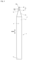
- FIG. 1 is a plan view of a cutting tool according to an embodiment.
- FIG. 2 is an enlarged view of FIG. 1 II.
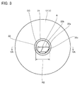
- FIG. 3 is a front view of the cutting tool according to the embodiment.
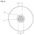
- FIG. 4 is a cross-sectional view taken along the line IV-IV of FIG.
- FIG. 5A is a cross-sectional view taken along the line VA-VA of FIG.
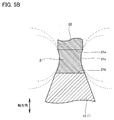
- FIG. 5B is a schematic cross-sectional view of the neck portion 21 when the outer peripheral surface 21c is formed of a curved line in which a plurality of arcs are connected in a cross section along the rotation axis A.
- FIG. 6 is an enlarged plan view of the cutting tool according to the first modification of the embodiment.
- FIG. 6 is an enlarged plan view of the cutting tool according to the first modification of the embodiment.
- FIG. 7 is a plan view of the cutting tool according to the second modification of the embodiment.
- FIG. 8 is a plan view of the cutting tool according to the third modification of the embodiment.
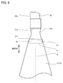
- FIG. 9 is a front view of the cutting tool according to the fourth modification of the embodiment.
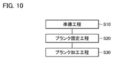
- FIG. 10 is a process diagram showing a method of manufacturing a cutting tool according to an embodiment.
- the present disclosure provides a cutting tool capable of improving machining accuracy and durability during cutting.
- the cutting tool according to the embodiment is composed of a main body made of cemented carbide and any one of a binderless cubic boron nitride polycrystal, a binderless diamond polycrystal and a diamond single crystal, and the main body part. It has a tip that is joined to.
- the main body has a first end and a second end opposite to the first end in the axial direction along the rotation axis of the main body.
- the tip portion has a neck portion protruding from the second end along the axial direction, and a blade portion connected to the neck portion and located at a position away from the second end portion in the axial direction.
- the neck portion includes a third end on the blade side and a fourth end opposite to the third end in the axial direction.
- the blade portion includes a cutting edge on the outer circumference.
- the cross-sectional area of the neck portion in the cross section orthogonal to the axial direction is larger than the area of the circumscribed circle of the cutting edge centered on the rotation axis in the front view seen from the tip end side along the axial direction at the fourth end.
- the length of the tip in the axial direction is larger than the diameter of the circumscribed circle.
- the neck is formed of a binderless cubic boron nitride polycrystal, a binderless diamond polycrystal or a diamond single crystal, the deflection near the tip of the cutting tool is reduced. As a result, the machining accuracy during cutting can be improved.
- the cross-sectional area of the neck portion at the second end is larger than the area of the circumscribed circle of the cutting edge centered on the rotation axis, so that the durability during cutting can be improved.
- the outer peripheral surface of the neck portion may be composed of a single arc in a cross section along the rotation axis.
- the cross-sectional area of the neck portion in the cross section orthogonal to the axial direction may be the minimum value between the third end and the fourth end.
- the minimum value may be 0.81 times or more and less than 1.0 times the area.
- the outer peripheral surface of the neck portion may be composed of a curved line in which a plurality of arcs are connected in a cross section along the rotation axis.
- the two arcs that are connected to each other may have a common tangent at the boundary.
- the cross-sectional area of the neck portion in the cross section orthogonal to the axial direction may be the minimum value between the third end and the fourth end. This minimum value may be 0.81 times or more and less than 1.0 times the area.
- the cross-sectional area of the neck portion in the cross section orthogonal to the axial direction is the third end rather than the midpoint between the third end and the fourth end in the axial direction. It may be the minimum value at a position close to.
- the diameter of the circumscribed circle of the cutting edge centered on the rotation axis in the front view seen from the tip side along the axial direction is 0.1 mm or more. It may be 3.0 mm or less.
- the tip portion may be made of a binderless cubic boron nitride polycrystal.
- the median diameter of the cubic boron nitride crystal grains contained in the binderless cubic boron nitride polycrystal may be 1.0 ⁇ m or less.
- the tip portion may be made of a binderless diamond polycrystalline material.
- the median diameter of the diamond crystal grains contained in the binderless diamond polycrystal may be 1.0 ⁇ m or less.
- the machining quality of the cutting surface can be improved.
- cutting tool 10 Structure of cutting tool according to the embodiment
- the configuration of the cutting tool (hereinafter referred to as “cutting tool 10”) according to the embodiment will be described below.
- FIG. 1 is a plan view of the cutting tool according to the embodiment.
- FIG. 2 is an enlarged view of FIG. 1 II.
- FIG. 3 is a front view of the cutting tool according to the embodiment. As shown in FIGS. 1 to 3, the cutting tool 10 is a radius end mill.
- the cutting tool 10 is, for example, a cutting tool for finishing.
- the cutting tool 10 cuts the work material by rotating around the rotation axis A.
- the direction along the rotation axis A is referred to as an axial direction.
- the cutting tool 10 has a main body portion 1 and a tip portion 2.
- the main body 1 is made of cemented carbide.
- Cemented carbide contains hard grains and a binder.
- the hard grains are, for example, tungsten carbide (WC) grains.
- WC tungsten carbide
- the average particle size of the hard grains is 1.0 ⁇ m or less.
- the average particle size of the hard grains may be 0.7 ⁇ m or less.
- the average particle size of the hard grains may be 0.5 ⁇ m or less.
- the binder is, for example, cobalt (Co).
- the average particle size of the hard particles in the cemented carbide is an average value of the equivalent circle diameters of the hard particles obtained by performing image processing on the cross-sectional image of the main body 1.
- the main body 1 has a first end 1a and a second end 1b in the axial direction.
- the second end 1b is the opposite end of the first end 1a.
- the main body portion 1 has a first portion 11 and a second portion 12.
- the first portion 11 is on the first end 1a side, and the second portion 12 is on the second end 1b side.
- the main body 1 does not have a neck.
- the first portion 11 extends from the second end 1b toward the first end 1a side.
- the cross-sectional area of the first portion 11 in the cross section orthogonal to the axial direction is constant along the axial direction.
- the first portion 11 has, for example, a cylindrical shape.
- the second part 12 extends from the first part 11 to the first end 1a.
- the cross-sectional area of the second portion 12 in the cross section orthogonal to the axial direction becomes smaller from the first portion 11 side to the first end 1a side.
- the second portion 12 has, for example, a truncated cone shape.
- the tip 2 is made of a binderless cubic boron nitride (cBN) polycrystal.
- the binderless cubic boron nitride polycrystal contains a plurality of cubic boron nitride particles.
- the balance of the binderless cubic boron nitride polycrystal contains boron nitride having a crystal structure other than cubic, such as hexagonal boron nitride (hBN) and wurtzite boron nitride (wBN), and unavoidable impurities. Binder is not included. That is, in the boron nitride polycrystal, the cubic boron nitride crystal grains are directly bonded to each other without using a binder.
- the median diameter (number basis) of the cubic boron nitride crystal grains is 1.0 ⁇ m or less. More preferably, in the binderless cubic boron nitride polycrystal, the median diameter of the cubic boron nitride crystal grains is 0.05 ⁇ m or less. In the binderless cubic boron nitride polycrystal, the median diameter of the cubic boron nitride crystal grains is, for example, 0.01 ⁇ m or more.
- the median diameter of the cubic boron nitride crystal grains in the binderless cubic boron nitride polycrystal is measured by the following method.
- an SEM (Scanning Electron Microscope) image is taken in the cross section of the tip portion 2.
- the size of the measurement field of view is 12 ⁇ m ⁇ 15 ⁇ m, and the observation magnification is 10000 times. Five SEM images are taken at different positions.
- the distribution of the equivalent circle diameter of the cubic boron nitride crystal grains is calculated by performing image analysis on five SEM images using image processing software (Win Roof Ver.7.4.5). To. Based on the distribution of the equivalent circle diameter, the median diameter of the cubic boron nitride crystal grains in the binderless cubic boron nitride polycrystal is calculated. Specifically, the median diameter of the cubic boron nitride crystal grains was calculated for each of the five captured SEM images using image processing software, and was obtained from each of the five SEM images. Calculate the average value of the median diameter. This average value is regarded as the median diameter of the cubic boron nitride crystal grains in the binderless cubic boron nitride polycrystal.
- the tip 2 may be made of a binderless diamond polycrystal.
- Binderless diamond polycrystals contain a plurality of diamond grains.
- the balance of the binderless diamond polycrystal may contain graphite, unavoidable impurities, etc., but does not contain the binder. That is, in the binderless diamond polycrystal, the diamond crystal grains are directly bonded to each other without using a binder.
- the tip portion 2 may be made of a diamond single crystal.
- the median diameter (number basis) of the diamond crystal grains is preferably 1.0 ⁇ m or less. In the binderless diamond polycrystal, the median diameter of the diamond crystal grains is more preferably 0.05 ⁇ m or less. In the binderless diamond polycrystal, the median diameter of the diamond crystal grains is, for example, 0.005 ⁇ m or more. The median diameter of the diamond crystal grains in the binderless diamond polycrystal is measured by the same method as the median diameter of the cubic boron nitride crystal grains in the binderless cubic boron nitride polycrystal.
- the tip portion 2 is fixed to the main body portion 1.
- the tip portion 2 has a neck portion 21 and a blade portion 22.
- the neck portion 21 projects from the second end 1b of the main body portion 1 along the axial direction.
- the blade portion 22 is connected to the neck portion 21.
- the blade portion 22 is located at a position farther from the second end 1b than the neck portion 21 in the axial direction.
- the neck portion 21 has a third end 21a and a fourth end 21b.
- the third end 21a and the fourth end 21b are the ends of the neck portion 21 in the axial direction.
- the third end 21a is on the blade portion 22 side.
- the fourth end 21b is on the opposite side of the third end 21a.
- the neck portion 21 is fixed to the end surface of the main body portion 1 on the second end 1b side, for example, by brazing. That is, the fourth end 21b of the neck portion 21 is fixed to the second end 1b of the main body portion 1.
- FIG. 4 is a cross-sectional view taken along the line IV-IV of FIG.
- the cross-sectional shape of the neck portion 21 is, for example, a circle.
- the cross-sectional shape of the neck portion 21 may be rectangular or polygonal.
- the cross-sectional area of the neck 21 in a cross section orthogonal to the axial direction of the neck is defined as the cross-sectional area S1.
- the diameter of the neck portion 21 in the cross section orthogonal to the axial direction is defined as the diameter R1.
- the diameter R1 is twice the distance between the outer peripheral surface 21c of the neck portion 21 and the rotation axis A in the cross section orthogonal to the axial direction.
- FIG. 5A is a cross-sectional view taken along the line VA-VA of FIG.
- the outer peripheral surface 21c is composed of a single arc (indicated by a dotted line in the drawing) in a cross section along the rotation axis A.
- the arc forming the outer peripheral surface 21c in the cross section along the rotation axis A is convex toward the rotation axis A side.
- the diameter R1 (cross-sectional area S1) is the minimum value at the position P.
- the position P is between the third end 21a and the fourth end 21b.
- the position P is preferably located closer to the third end 21a than the midpoint C between the third end 21a and the fourth end 21b in the axial direction.
- the outer peripheral surface 21c may be formed by a curved line in which a plurality of arcs are connected in a cross section along the rotation axis A.
- FIG. 5B is a schematic cross-sectional view of the neck portion 21 when the outer peripheral surface 21c is formed of a curved line in which a plurality of arcs are connected in a cross section along the rotation axis A.
- the two arcs (indicated by the dotted line in the figure) that are connected to each other have a common tangent line (indicated by the alternate long and short dash line in the figure) at the boundary. .. That is, the two arcs that are connected to each other are smoothly connected at the boundary.
- the blade portion 22 has a cutting edge 22a, a rake surface 22b, and a flank surface 22c.
- the rake face 22b is a plane parallel to the rotation axis A.
- the rake face 22b and the flank surface 22c are connected to each other on the outer circumference of the blade portion 22.
- the cutting edge 22a is formed on the ridgeline between the rake face 22b and the flank surface 22c. As a result, a part of the outer circumference of the blade portion 22 becomes a cutting edge 22a.
- the blade portion 22 has a shape that is non-point symmetric with respect to the rotation axis A when viewed from the blade portion 22 side along the axial direction.
- the circumscribed circle CC of the cutting edge 22a centered on the rotation axis A in the front view seen from the blade portion 22 side along the axial direction is shown by a dotted line.
- the diameter of the circumscribed circle CC is defined as the diameter R2.
- the area of the circumscribed circle CC is defined as the area S2.
- the cross-sectional area S1 at the fourth end 21b is larger than the area S2.
- the minimum value of the cross-sectional area S1 is preferably 0.81 times or more and less than 1.0 times the area S2.
- the diameter R1 at the fourth end 21b is larger than the diameter R2.
- the minimum value of the diameter R1 is preferably 0.9 times or more and less than 1.0 times the diameter R2.
- the length L of the tip portion 2 in the axial direction is larger than the diameter R2.
- the length L is, for example, three times or less the diameter R2.
- the diameter R2 is preferably 0.5 mm or more and 3.0 mm or less.
- FIG. 6 is an enlarged plan view of the cutting tool according to the first modification of the embodiment.
- the tip portion 2 may further have a convex portion 23.
- the convex portion 23 projects from the fourth end 21b along the direction from the third end 21a to the fourth end 21b.
- a recess 1c is formed on the end surface of the main body 1 (second portion 12) on the second end 1b side.
- the end surface of the main body 1 on the second end 1b side is recessed in the recess 1c toward the first end 1a side.
- a convex portion 23 is inserted into the concave portion 1c. In this case, since the convex portion 23 and the concave portion 1c are brazed and the tip portion 2 is fixed to the main body portion 1, the brazed joint area can be increased.
- FIG. 7 is a plan view of the cutting tool according to the second modification of the embodiment.
- FIG. 8 is a plan view of the cutting tool according to the third modification of the embodiment.
- the radius end mill is mentioned as an example of the cutting tool 10, but the cutting tool 10 is not limited to this.
- the cutting tool 10 may be a ball end mill.
- the cutting tool 10 may be a drill, as shown in FIG.
- FIG. 9 is a front view of the cutting tool according to the fourth modification of the embodiment.
- the blade portion 22 may have a shape symmetrical with respect to the rotation axis A as shown in FIG. 9 when viewed from the blade portion 22 side along the axial direction.
- FIG. 10 is a process diagram showing a method of manufacturing a cutting tool according to an embodiment. As shown in FIG. 10, the manufacturing method of the cutting tool 10 includes a preparation step S10, a blank fixing step S20, and a blank processing step S30.
- the main body 1 and the blank are prepared.
- the blank comprises a binderless cubic boron nitride polycrystal, a binderless diamond polycrystal or a diamond single crystal.
- Binderless cubic boron nitride polycrystals are formed by directly converting hexagonal boron nitride to cubic boron nitride under predetermined temperature and pressure conditions without passing through wurtzite-type boron nitride.
- Binderless diamond polycrystals are formed by directly converting graphite into diamond under predetermined temperature and pressure conditions.
- the diamond single crystal is formed by, for example, a CVD (Chemical Vapor Deposition) method.
- the blank fixing step S20 the blank made of the above-mentioned binderless cubic boron nitride polycrystal, binderless diamond polycrystal or diamond single crystal is fixed to the second end 1b side of the main body 1.
- This fixing is performed, for example, by brazing.
- the tip portion 2 (neck portion 21 and blade portion 22) is formed by processing the above blank.
- the processing on the blank is performed by, for example, polishing processing using a grindstone, electric discharge machining, laser machining, or the like. As described above, the cutting tool 10 is prepared.
- the neck portion 21 is formed of a binderless cubic boron nitride polycrystal, a binderless diamond polycrystal, or a diamond single crystal. Since the binderless cubic boron nitride polycrystal, the binderless diamond polycrystal and the diamond single crystal do not contain a binder, the sintered body of the cubic boron nitride containing the binder and the binder and the sintered body of the diamond Younger rate is higher than. Therefore, according to the cutting tool 10, the rigidity of the neck portion 21 is improved, and as a result, the accuracy of the cutting process can be improved.
- the tip portion 2 When the tip portion 2 has a shape that is non-point symmetric with respect to the rotation axis A in the front view seen from the tip portion 2 side along the axial direction, the nonuniformity of the centrifugal force due to the rotation around the rotation axis A Due to this, vibration may occur.
- the tip portion 2 since the rigidity of the neck portion 21 is improved, the tip portion 2 has a shape that is non-point symmetric with respect to the rotation axis A when viewed from the tip portion 2 side along the axial direction. Even if it has, the above-mentioned vibration can be suppressed.
- the cross-sectional area S1 at the fourth end 21b is larger than the area S2. Therefore, according to the cutting tool 10, the joint strength between the tip portion 2 (neck portion 21) and the main body portion 1 is ensured, and as a result, the durability during cutting can be improved.
- the outer peripheral surface 21c is composed of one arc in the cross section along the rotation axis A (composed of two or more arcs having a common tangent at the boundary), the outer peripheral surface 21c is composed of a smooth surface. Therefore, stress concentration on the outer peripheral surface 21c can be suppressed.
- the minimum value of the cross-sectional area S1 is 0.81 times or more and less than 1.0 times the area S2 (when the minimum value of the diameter R1 is 0.9 times or more and less than 1.0 times the diameter R2), the neck portion 21 Even if there is a constricted part, the durability of the neck portion 21 can be ensured.
- the bending moment due to the cutting force acting on the cutting edge 22a increases as the distance from the cutting edge 22a increases. Therefore, the neck portion 21 has a constricted portion, and the farther the constricted portion is from the cutting edge 22a, the more likely it is that the constricted portion will be broken due to the above-mentioned bending moment.
- the position P is closer to the third end 21a than the midpoint C, the distance between the constricted portion and the cutting edge 22a is relatively small, which is caused by the bending moment caused by the above moment. It is possible to suppress the breakage.
- the machining quality of the cutting surface depends on the size of crystal grains in the material that makes up the cutting edge. Therefore, when the median diameter of the cubic boron nitride crystal grains in the binderless cubic boron nitride polycrystal and the median diameter of the diamond crystal grains in the binderless diamond polycrystal are 1 ⁇ m or less, the processed grade of the cut surface is deteriorated. It can be increased (specifically, the surface roughness of the cut surface is reduced).
- 1 Main body 1a 1st end, 1b 2nd end, 1c recess, 10 cutting tool, 11 1st part, 12 2nd part, 2 tip part, 21 neck part, 21a 3rd end, 21b 4th end, 21c outer circumference Surface, 22 blade, 22a cutting edge, 22b rake surface, 22c flank, 23 convex, A rotation axis, C midpoint, CC circumscribed circle, L length, P position, R1, R2 diameter, S1 cross-sectional area, S2 area, S10 preparation process, S20 blank fixing process, S30 blank processing process.
Landscapes
- Engineering & Computer Science (AREA)
- Mechanical Engineering (AREA)
- Cutting Tools, Boring Holders, And Turrets (AREA)
- Milling Processes (AREA)
Priority Applications (4)
| Application Number | Priority Date | Filing Date | Title |
|---|---|---|---|
| US17/051,798 US20230115988A1 (en) | 2019-06-13 | 2020-02-27 | Cutting tool |
| CN202080002618.5A CN112399898A (zh) | 2019-06-13 | 2020-02-27 | 切削工具 |
| JP2020550195A JPWO2020250499A1 (https=) | 2019-06-13 | 2020-02-27 | |
| EP20797013.8A EP3778084A4 (en) | 2019-06-13 | 2020-02-27 | CUTTING TOOL |
Applications Claiming Priority (2)
| Application Number | Priority Date | Filing Date | Title |
|---|---|---|---|
| JP2019-110246 | 2019-06-13 | ||
| JP2019110246 | 2019-06-13 |
Publications (1)
| Publication Number | Publication Date |
|---|---|
| WO2020250499A1 true WO2020250499A1 (ja) | 2020-12-17 |
Family
ID=73781753
Family Applications (1)
| Application Number | Title | Priority Date | Filing Date |
|---|---|---|---|
| PCT/JP2020/008122 Ceased WO2020250499A1 (ja) | 2019-06-13 | 2020-02-27 | 切削工具 |
Country Status (5)
| Country | Link |
|---|---|
| US (1) | US20230115988A1 (https=) |
| EP (1) | EP3778084A4 (https=) |
| JP (1) | JPWO2020250499A1 (https=) |
| CN (1) | CN112399898A (https=) |
| WO (1) | WO2020250499A1 (https=) |
Cited By (2)
| Publication number | Priority date | Publication date | Assignee | Title |
|---|---|---|---|---|
| JPWO2021261380A1 (https=) * | 2020-06-22 | 2021-12-30 | ||
| JPWO2023282173A1 (https=) * | 2021-07-08 | 2023-01-12 |
Families Citing this family (1)
| Publication number | Priority date | Publication date | Assignee | Title |
|---|---|---|---|---|
| WO2021054019A1 (ja) * | 2019-09-18 | 2021-03-25 | 住友電工ハードメタル株式会社 | ダイヤモンド切削工具 |
Citations (10)
| Publication number | Priority date | Publication date | Assignee | Title |
|---|---|---|---|---|
| DE102005009030A1 (de) * | 2005-02-18 | 2006-08-24 | Technische Universität Berlin | Spanendes Werkzeug insbesondere für den Mikro- und Präzisionsformenbau |
| JP2006255814A (ja) * | 2005-03-16 | 2006-09-28 | Micro Diamond Corp | マイクロ回転工具 |
| JP2009178791A (ja) * | 2008-01-30 | 2009-08-13 | Kyocera Corp | 回転工具およびその製造方法 |
| WO2012114641A1 (ja) * | 2011-02-23 | 2012-08-30 | 京セラ株式会社 | 切削工具およびその製造方法 |
| WO2013190977A1 (ja) * | 2012-06-21 | 2013-12-27 | 住友電工ハードメタル株式会社 | 切削工具 |
| JP2015009285A (ja) * | 2013-06-26 | 2015-01-19 | 三菱マテリアル株式会社 | エンドミル |
| JP2015530263A (ja) * | 2012-07-11 | 2015-10-15 | スミス インターナショナル インコーポレイテッド | Pcbn移行層を有する熱的に安定なpcd |
| JP2017119333A (ja) | 2015-12-28 | 2017-07-06 | 日進工具株式会社 | エンドミルとその製造方法 |
| JP2018122365A (ja) | 2017-01-30 | 2018-08-09 | 三菱日立ツール株式会社 | ボールエンドミル |
| JP2019110246A (ja) | 2017-12-19 | 2019-07-04 | 池上通信機株式会社 | 操作モジュールロック機構 |
Family Cites Families (31)
| Publication number | Priority date | Publication date | Assignee | Title |
|---|---|---|---|---|
| CH275269A (de) * | 1948-07-09 | 1951-05-15 | Sandvikens Jernverks Ab | Zahnbohrer. |
| EP0870073B1 (en) * | 1995-11-30 | 2002-02-13 | Sandvik Aktiebolag | Coated cutting insert and method of making it |
| JPH10113809A (ja) * | 1996-10-11 | 1998-05-06 | Hitachi Tool Eng Co Ltd | 高速用ボ−ルエンドミル |
| CN2283536Y (zh) * | 1997-03-31 | 1998-06-10 | 河南第一工具厂 | 摩托车用硬质合金阶梯扩锪复合刀 |
| JPH1148016A (ja) * | 1997-07-30 | 1999-02-23 | Toshiba Tungaloy Co Ltd | 小径ドリル |
| JPH11156622A (ja) * | 1997-11-25 | 1999-06-15 | Hitachi Tool Eng Ltd | 球状刃エンドミル |
| JP3711255B2 (ja) * | 2001-09-21 | 2005-11-02 | 日立ツール株式会社 | テーパ部を有するエンドミル |
| JP2007185736A (ja) * | 2006-01-12 | 2007-07-26 | Sumitomo Electric Hardmetal Corp | エンドミル |
| JPWO2007097474A1 (ja) * | 2006-02-23 | 2009-07-16 | 国立大学法人東京農工大学 | 非軸対称刃ドリル |
| WO2009072200A1 (ja) * | 2007-12-05 | 2009-06-11 | Osg Corporation | 小径回転加工工具 |
| CN201500804U (zh) * | 2009-09-03 | 2010-06-09 | 上海凯思尔电子有限公司 | 一种平头钻刀 |
| EP2495057B1 (en) * | 2009-10-30 | 2017-03-29 | Mitsubishi Materials Corporation | Surface coated cutting tool with excellent chip resistance |
| CN101758212A (zh) * | 2009-10-30 | 2010-06-30 | 西安泽豪实业有限责任公司 | 一种用于硬质合金切割的金刚石超薄切片配方及生产工艺 |
| US9358079B2 (en) * | 2010-02-11 | 2016-06-07 | Sybron Canada Lp | Bur and method of making same |
| JP5146493B2 (ja) * | 2010-06-28 | 2013-02-20 | 三菱マテリアル株式会社 | エンドミルおよびその製造方法 |
| JP5488824B2 (ja) * | 2010-08-12 | 2014-05-14 | 三菱マテリアル株式会社 | 硬質難削材の高速切削加工で硬質被覆層がすぐれた耐剥離性とすぐれた耐摩耗性を発揮する表面被覆切削工具 |
| KR101239045B1 (ko) * | 2010-12-15 | 2013-03-04 | 대구텍 유한회사 | 비대칭 회전 절삭 공구 |
| CN103635599B (zh) * | 2011-06-27 | 2016-03-30 | 京瓷株式会社 | 硬质合金及切削工具 |
| DE102012224437A1 (de) * | 2012-12-27 | 2014-07-03 | Robert Bosch Gmbh | Bohrwerkzeug |
| WO2014103972A1 (ja) * | 2012-12-28 | 2014-07-03 | 京セラ株式会社 | ドリルおよびそれを用いた切削加工物の製造方法 |
| CN203600087U (zh) * | 2013-10-10 | 2014-05-21 | 上海鑫轮超硬磨具有限公司 | 基于硬质合金杆的cbn内圆高速砂轮 |
| TWI540009B (zh) * | 2014-11-28 | 2016-07-01 | Metal Ind Res & Dev Ct | The blade has a non-symmetrical microstructure of the tool |
| CN104911431A (zh) * | 2015-06-26 | 2015-09-16 | 河源正信硬质合金有限公司 | 一种强韧性超耐磨硬质合金及其制造方法 |
| CN105132779B (zh) * | 2015-07-31 | 2018-03-30 | 株洲硬质合金集团有限公司 | 碳化钨基硬质合金以及其制备方法 |
| CN205043228U (zh) * | 2015-10-28 | 2016-02-24 | 中航湖南通用航空发动机有限公司 | 一种非对称刃变螺旋角铣刀 |
| CN206912325U (zh) * | 2017-05-27 | 2018-01-23 | 东莞富兰地工具股份有限公司 | 非对称双刃铣刀 |
| JP6311059B1 (ja) * | 2017-09-20 | 2018-04-11 | 株式会社芝技研 | 細いドリル |
| CN107695402A (zh) * | 2017-11-20 | 2018-02-16 | 中山市园丰精密刃具有限公司 | 一种外观成型刀 |
| CN109249071B (zh) * | 2018-08-30 | 2020-12-25 | 中国工程物理研究院机械制造工艺研究所 | 一种阵列微槽微铣刀 |
| CN208758694U (zh) * | 2018-09-03 | 2019-04-19 | 株洲钻石切削刀具股份有限公司 | 一种铣削刀具 |
| CN109321798A (zh) * | 2018-10-30 | 2019-02-12 | 湖南工业大学 | 一种硬质合金刀具涂层材料及其制备方法 |
-
2020
- 2020-02-27 WO PCT/JP2020/008122 patent/WO2020250499A1/ja not_active Ceased
- 2020-02-27 EP EP20797013.8A patent/EP3778084A4/en not_active Withdrawn
- 2020-02-27 JP JP2020550195A patent/JPWO2020250499A1/ja active Pending
- 2020-02-27 US US17/051,798 patent/US20230115988A1/en not_active Abandoned
- 2020-02-27 CN CN202080002618.5A patent/CN112399898A/zh active Pending
Patent Citations (10)
| Publication number | Priority date | Publication date | Assignee | Title |
|---|---|---|---|---|
| DE102005009030A1 (de) * | 2005-02-18 | 2006-08-24 | Technische Universität Berlin | Spanendes Werkzeug insbesondere für den Mikro- und Präzisionsformenbau |
| JP2006255814A (ja) * | 2005-03-16 | 2006-09-28 | Micro Diamond Corp | マイクロ回転工具 |
| JP2009178791A (ja) * | 2008-01-30 | 2009-08-13 | Kyocera Corp | 回転工具およびその製造方法 |
| WO2012114641A1 (ja) * | 2011-02-23 | 2012-08-30 | 京セラ株式会社 | 切削工具およびその製造方法 |
| WO2013190977A1 (ja) * | 2012-06-21 | 2013-12-27 | 住友電工ハードメタル株式会社 | 切削工具 |
| JP2015530263A (ja) * | 2012-07-11 | 2015-10-15 | スミス インターナショナル インコーポレイテッド | Pcbn移行層を有する熱的に安定なpcd |
| JP2015009285A (ja) * | 2013-06-26 | 2015-01-19 | 三菱マテリアル株式会社 | エンドミル |
| JP2017119333A (ja) | 2015-12-28 | 2017-07-06 | 日進工具株式会社 | エンドミルとその製造方法 |
| JP2018122365A (ja) | 2017-01-30 | 2018-08-09 | 三菱日立ツール株式会社 | ボールエンドミル |
| JP2019110246A (ja) | 2017-12-19 | 2019-07-04 | 池上通信機株式会社 | 操作モジュールロック機構 |
Non-Patent Citations (1)
| Title |
|---|
| See also references of EP3778084A4 |
Cited By (5)
| Publication number | Priority date | Publication date | Assignee | Title |
|---|---|---|---|---|
| JPWO2021261380A1 (https=) * | 2020-06-22 | 2021-12-30 | ||
| JP7133118B2 (ja) | 2020-06-22 | 2022-09-07 | 住友電工ハードメタル株式会社 | 切削工具 |
| US12186815B2 (en) | 2020-06-22 | 2025-01-07 | Sumitomo Electric Hardmetal Corp. | Cutting tool |
| JPWO2023282173A1 (https=) * | 2021-07-08 | 2023-01-12 | ||
| WO2023282173A1 (ja) * | 2021-07-08 | 2023-01-12 | クラレノリタケデンタル株式会社 | 歯科用エンドミル、及び加工方法 |
Also Published As
| Publication number | Publication date |
|---|---|
| JPWO2020250499A1 (https=) | 2020-12-17 |
| EP3778084A4 (en) | 2022-02-09 |
| US20230115988A1 (en) | 2023-04-13 |
| EP3778084A1 (en) | 2021-02-17 |
| CN112399898A (zh) | 2021-02-23 |
Similar Documents
| Publication | Publication Date | Title |
|---|---|---|
| WO2020250499A1 (ja) | 切削工具 | |
| US20070172321A1 (en) | Ball endmill | |
| TWI750172B (zh) | 切削工具 | |
| CN109414769B (zh) | 端铣刀主体和圆角端铣刀 | |
| US11865630B2 (en) | Rotary tool | |
| WO2019073752A1 (ja) | 回転切削工具 | |
| JP5814611B2 (ja) | エンドミル | |
| EP4190473A1 (en) | Drill | |
| CN102626853B (zh) | 金刚石包覆切削工具 | |
| JP6029004B2 (ja) | Pcdドリル | |
| US11440108B2 (en) | Rotary cutting tool | |
| WO2010086988A1 (ja) | ダブルアングルドリル | |
| CN103128345A (zh) | Pcd钻头 | |
| JP3477183B2 (ja) | ダイヤモンド被覆切削工具 | |
| CN112355333A (zh) | 一种刀具及其刀头结构 | |
| CN114450123B (zh) | 工具以及工具的制造方法 | |
| CN114302783B (zh) | 钻头 | |
| JP7313599B2 (ja) | 硬質焼結体用の基材、硬質焼結体および切削工具 | |
| WO2021260778A1 (ja) | 工具及び工具の製造方法 | |
| JP3639227B2 (ja) | 脆性材料用穴明け工具 | |
| JP5349164B2 (ja) | 切削工具 | |
| CN115702053B (zh) | 切削工具 | |
| JP2010036295A (ja) | ドリル及びドリルの製造方法 | |
| CN113631307B (zh) | 硬质烧结体用基材、硬质烧结体及切削工具 | |
| JP2003326410A (ja) | センタドリル |
Legal Events
| Date | Code | Title | Description |
|---|---|---|---|
| ENP | Entry into the national phase |
Ref document number: 2020550195 Country of ref document: JP Kind code of ref document: A |
|
| ENP | Entry into the national phase |
Ref document number: 2020797013 Country of ref document: EP Effective date: 20201104 |
|
| NENP | Non-entry into the national phase |
Ref country code: DE |
|
| WWW | Wipo information: withdrawn in national office |
Ref document number: 2020797013 Country of ref document: EP |