WO2020241589A1 - 指紋認証センサー付き画像表示装置の表面保護フィルム用基材フィルム、表面保護フィルムおよび画像表示装置 - Google Patents
指紋認証センサー付き画像表示装置の表面保護フィルム用基材フィルム、表面保護フィルムおよび画像表示装置 Download PDFInfo
- Publication number
- WO2020241589A1 WO2020241589A1 PCT/JP2020/020595 JP2020020595W WO2020241589A1 WO 2020241589 A1 WO2020241589 A1 WO 2020241589A1 JP 2020020595 W JP2020020595 W JP 2020020595W WO 2020241589 A1 WO2020241589 A1 WO 2020241589A1
- Authority
- WO
- WIPO (PCT)
- Prior art keywords
- film
- image display
- display device
- fingerprint authentication
- surface protective
- Prior art date
- Legal status (The legal status is an assumption and is not a legal conclusion. Google has not performed a legal analysis and makes no representation as to the accuracy of the status listed.)
- Ceased
Links
Images

Classifications
-
- G—PHYSICS
- G02—OPTICS
- G02B—OPTICAL ELEMENTS, SYSTEMS OR APPARATUS
- G02B5/00—Optical elements other than lenses
- G02B5/30—Polarising elements
- G02B5/3025—Polarisers, i.e. arrangements capable of producing a definite output polarisation state from an unpolarised input state
- G02B5/3033—Polarisers, i.e. arrangements capable of producing a definite output polarisation state from an unpolarised input state in the form of a thin sheet or foil, e.g. Polaroid
- G02B5/3041—Polarisers, i.e. arrangements capable of producing a definite output polarisation state from an unpolarised input state in the form of a thin sheet or foil, e.g. Polaroid comprising multiple thin layers, e.g. multilayer stacks
- G02B5/305—Polarisers, i.e. arrangements capable of producing a definite output polarisation state from an unpolarised input state in the form of a thin sheet or foil, e.g. Polaroid comprising multiple thin layers, e.g. multilayer stacks including organic materials, e.g. polymeric layers
-
- G—PHYSICS
- G02—OPTICS
- G02B—OPTICAL ELEMENTS, SYSTEMS OR APPARATUS
- G02B5/00—Optical elements other than lenses
- G02B5/30—Polarising elements
- G02B5/3083—Birefringent or phase retarding elements
-
- B—PERFORMING OPERATIONS; TRANSPORTING
- B32—LAYERED PRODUCTS
- B32B—LAYERED PRODUCTS, i.e. PRODUCTS BUILT-UP OF STRATA OF FLAT OR NON-FLAT, e.g. CELLULAR OR HONEYCOMB, FORM
- B32B27/00—Layered products comprising a layer of synthetic resin
-
- B—PERFORMING OPERATIONS; TRANSPORTING
- B32—LAYERED PRODUCTS
- B32B—LAYERED PRODUCTS, i.e. PRODUCTS BUILT-UP OF STRATA OF FLAT OR NON-FLAT, e.g. CELLULAR OR HONEYCOMB, FORM
- B32B27/00—Layered products comprising a layer of synthetic resin
- B32B27/36—Layered products comprising a layer of synthetic resin comprising polyesters
-
- G—PHYSICS
- G02—OPTICS
- G02B—OPTICAL ELEMENTS, SYSTEMS OR APPARATUS
- G02B1/00—Optical elements characterised by the material of which they are made; Optical coatings for optical elements
- G02B1/08—Optical elements characterised by the material of which they are made; Optical coatings for optical elements made of polarising materials
-
- G—PHYSICS
- G02—OPTICS
- G02B—OPTICAL ELEMENTS, SYSTEMS OR APPARATUS
- G02B1/00—Optical elements characterised by the material of which they are made; Optical coatings for optical elements
- G02B1/10—Optical coatings produced by application to, or surface treatment of, optical elements
- G02B1/14—Protective coatings, e.g. hard coatings
-
- G—PHYSICS
- G02—OPTICS
- G02B—OPTICAL ELEMENTS, SYSTEMS OR APPARATUS
- G02B5/00—Optical elements other than lenses
- G02B5/30—Polarising elements
-
- G—PHYSICS
- G02—OPTICS
- G02F—OPTICAL DEVICES OR ARRANGEMENTS FOR THE CONTROL OF LIGHT BY MODIFICATION OF THE OPTICAL PROPERTIES OF THE MEDIA OF THE ELEMENTS INVOLVED THEREIN; NON-LINEAR OPTICS; FREQUENCY-CHANGING OF LIGHT; OPTICAL LOGIC ELEMENTS; OPTICAL ANALOGUE/DIGITAL CONVERTERS
- G02F1/00—Devices or arrangements for the control of the intensity, colour, phase, polarisation or direction of light arriving from an independent light source, e.g. switching, gating or modulating; Non-linear optics
- G02F1/01—Devices or arrangements for the control of the intensity, colour, phase, polarisation or direction of light arriving from an independent light source, e.g. switching, gating or modulating; Non-linear optics for the control of the intensity, phase, polarisation or colour
- G02F1/13—Devices or arrangements for the control of the intensity, colour, phase, polarisation or direction of light arriving from an independent light source, e.g. switching, gating or modulating; Non-linear optics for the control of the intensity, phase, polarisation or colour based on liquid crystals, e.g. single liquid crystal display cells
- G02F1/133—Constructional arrangements; Operation of liquid crystal cells; Circuit arrangements
- G02F1/1333—Constructional arrangements; Manufacturing methods
- G02F1/1335—Structural association of cells with optical devices, e.g. polarisers or reflectors
-
- G—PHYSICS
- G02—OPTICS
- G02F—OPTICAL DEVICES OR ARRANGEMENTS FOR THE CONTROL OF LIGHT BY MODIFICATION OF THE OPTICAL PROPERTIES OF THE MEDIA OF THE ELEMENTS INVOLVED THEREIN; NON-LINEAR OPTICS; FREQUENCY-CHANGING OF LIGHT; OPTICAL LOGIC ELEMENTS; OPTICAL ANALOGUE/DIGITAL CONVERTERS
- G02F1/00—Devices or arrangements for the control of the intensity, colour, phase, polarisation or direction of light arriving from an independent light source, e.g. switching, gating or modulating; Non-linear optics
- G02F1/01—Devices or arrangements for the control of the intensity, colour, phase, polarisation or direction of light arriving from an independent light source, e.g. switching, gating or modulating; Non-linear optics for the control of the intensity, phase, polarisation or colour
- G02F1/13—Devices or arrangements for the control of the intensity, colour, phase, polarisation or direction of light arriving from an independent light source, e.g. switching, gating or modulating; Non-linear optics for the control of the intensity, phase, polarisation or colour based on liquid crystals, e.g. single liquid crystal display cells
- G02F1/133—Constructional arrangements; Operation of liquid crystal cells; Circuit arrangements
- G02F1/1333—Constructional arrangements; Manufacturing methods
- G02F1/1335—Structural association of cells with optical devices, e.g. polarisers or reflectors
- G02F1/13363—Birefringent elements, e.g. for optical compensation
Definitions
- the present invention relates to a base film for a surface protective film of an image display device having a fingerprint authentication sensor, a surface protective film, and an image display device.
- a surface protection film has been attached to an image display device to protect the surface.
- the surface protective film has the purpose of not only preventing scratches on the surface but also preventing scattering when the image cell or the surface glass plate is broken, and biaxially stretched polyester having excellent impact resistance has been mainly used. .. Further, in the image display device, a biaxially stretched polyester film has been used as a shatterproof film for a touch sensor member and a glass member.
- Patent Documents 1 and 2 face recognition systems and fingerprint recognition systems have come to be adopted in order to ensure a high degree of security.
- Patent Documents 1 and 2 In order to increase the screen size of such mobile terminals due to the size limitation of mobile, the entire main body is used as a display screen, and an authentication system is installed in the screen (the image display area when viewed from the visual side and behind it). It has been proposed to incorporate the sensor of.
- organic electroluminescence (organic EL) image display device a fingerprint authentication sensor can be operated through a gap between pixels of an image display cell, and such a method is becoming widespread.
- a polarizing plate is provided on the visible side of the sensor for authentication.
- a surface protective film is provided on the visible side of the polarizing plate.
- the fingerprint authentication system may not operate (recognize) or malfunction (misidentified value).
- the present invention has been made against the background of the problems of the prior art.
- a base film for a surface protective film of an image display device with a fingerprint authentication sensor that satisfies the following (1) to (4).
- the base film is a polyester film having an easy-adhesion layer on at least one side.
- the base film has a retardation axis variation of 7 ° / m or less.
- the base film Has a retardation of 3000 to 30000 nm.
- the base film has an Nz coefficient of 2.5 or less.
- Item 3. Item 2. A surface protective film for an image display device with a fingerprint authentication sensor, in which a functional layer is laminated on an easily adhesive layer surface of the base film according to Item 1 or 2.
- the surface protective film according to Item 3 is provided on the visible side of the polarizing plate.
- An image display device in which the angle formed by the slow axis direction of the surface protective film and the quenching axis direction of the polarizing element of the polarizing plate is 0 ° ⁇ 6 ° or less, or 90 ° ⁇ 6 ° or less. (In addition, in the above, “below” shall be applied only to the numerical value next to " ⁇ ".)
- the fingerprint authentication system operates normally even when it is attached to the surface of an image display device equipped with a fingerprint authentication sensor, and even when observed through polarized sunglasses, rainbow unevenness is suppressed and the base film for surface protection film has excellent visibility.
- Surface protective films and image display devices can be provided.
- the image display device of the present invention is an image display device with a fingerprint authentication sensor having a fingerprint authentication sensor. It is preferable to have a polarizing plate on the visual side of the fingerprint authentication sensor.
- the fingerprint authentication sensor fingerprint authentication sensor unit
- the fingerprint authentication sensor is installed inside the display screen (the image display area when viewed from the visual side and behind it).
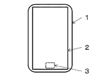
- the inside of the display screen (the image display area when viewed from the visual side and the back thereof) is the state shown in FIGS. 1 and 2.
- the type installed inside the display screen is also called a screen embedded type.
- the outside of the fingerprint authentication sensor is installed at the back of the screen when viewed from the visual side. In FIG.
- an image display cell for example, an organic EL cell
- a polarizing plate preferably a circular polarizing plate is preferable when the image display cell is an organic EL cell
- the surface protective film of the present invention (a base film for a surface protective film of the present invention in which a functional layer is laminated) is arranged on the visible side of the polarizing plate.
- the image display device of the present invention is preferably a smartphone, a mobile PC, a PDA, a game machine, a camera, an electronic dictionary, or the like, and a smartphone is particularly preferable.
- the image display cell used in the image display device of the present invention is not particularly limited, but a liquid crystal display cell or an organic EL (OLED) cell is a preferable example in that it can be made smaller and thinner.
- the organic EL cell is a preferable example because the fingerprint authentication sensor can be operated through the gap between the pixels of the cell.
- the fingerprint authentication sensor examples include an optical type, an ultrasonic type, a capacitance type, an electric field strength measurement type, a pressure sensitive type, and a heat sensitive type.
- the fingerprint authentication sensor is not particularly limited, but is optical due to compatibility with the configuration of the image display device of the present invention.
- the type or ultrasonic type is preferable, and the optical type is particularly preferable.
- As an optical fingerprint authentication sensor for example, it is commercially available from Synaptics under the trade name "Clear ID”.
- As an ultrasonic fingerprint approval sensor for example, it is commercially available from Qualcomm Technologies, Inc. under the trade name "Qualcomm Fingerprint Sensors”.
- the image display device is in a state where a polarizing plate is provided on the visual side of the fingerprint authentication sensor.
- the polarizing plate generally includes a polarizer having a function of generating polarized light and a polarizer protective film for protecting the polarizer, but the polarizer protective film is laminated only on one side of the polarizer. It may be a thing, or it may be only a polarizer.
- the polarizer include a thin film in which iodine or an organic dichroic dye is adsorbed on uniaxially oriented polyvinyl alcohol, and an alignment film composed of a liquid crystal compound and an organic dichroic dye, but are particularly limited. Can be used without.
- the polarizing element protective film is not particularly limited, but unstretched films such as cellulose-based, polyester-based, cyclic polyolefin-based, acrylic-based, and polycarbonate-based films and stretched films can be used.
- the quenching axis (absorption axis) of the polarizer and the main orientation direction of the stretched film are parallel or perpendicular.
- parallel or vertical means that the angle formed by the quenching axis of the polarizer and the main orientation direction of the stretched film does not have to be exactly 0 degrees or 90 degrees, and the allowable width of deviation from 0 degrees or 90 degrees.
- Is ⁇ 6 degrees a more preferred tolerance is ⁇ 5 degrees, a more preferred tolerance is ⁇ 4 degrees, a particularly preferred tolerance is ⁇ 3 degrees, and the most preferred tolerance is ⁇ 2 degrees. ..
- the quenching axis of the polarizing element of the polarizing plate may be parallel to the long side of the screen, perpendicular to it, or in the direction of 45 degrees. These directions are determined by the type and purpose of the image display cell, and are not particularly limited in the present invention. For example, in the case of an organic EL display cell, it is often arranged at 45 degrees.
- a retardation layer may be provided between the polarizer and the image display cell.
- the retardation layer may be a retardation film in which a resin is stretched, or may be an alignment film of a liquid crystal compound coated and oriented with a liquid crystal compound.
- a circular polarizing plate provided with a 1/4 wavelength layer as a retardation layer is used in order to suppress reflection of the metal wiring of the cell.
- the retardation layer of the circular polarizing plate is arranged on the organic EL cell side.
- the surface protective film of the present invention preferably has a functional layer such as a hard coat layer, an antireflection layer, a low reflection layer, and an antiglare layer laminated on at least one surface of the base film for a surface protection film.
- the surface protective film of the present invention is located on the surface of an image display device and prevents scratches on the image display surface, or is glass when a glass member such as an image display cell, a touch sensor, or a surface cover glass is broken by an impact. It is preferable to have a hard coat layer in order to prevent scattering of the glass.
- the surface protective film is preferably one that can be peeled off and replaced when the film itself is damaged.
- the surface protective film is preferably a base-less adhesive sheet for optics and is attached to an image display device.
- a hard coat layer can be provided on the surface protective film by applying a hard coat coating liquid for imparting scratch resistance and antifouling property to at least one surface of a transparent film as a base material.
- the hard coat layer is laminated on the visible side of the film as the base material.
- the hard coat applied to the present invention is not limited to any function.
- a conventionally known hard coat layer can be used.
- the antireflection layer, the low reflection layer, and the antiglare layer are not particularly limited, and conventionally known ones can be used.
- a combination of a low reflection layer and an antiglare layer, a combination of an antireflection layer and an antiglare layer, and the like can also be preferably used. Further, a hard coat layer having an antireflection function, a low reflection function, and / or an antiglare function can also be preferably used.
- the surface protective film may be used as one protective film by laminating two base films with an optical adhesive film.
- the film used as the base material of the surface protective film of the present invention is wound in the form of a roll, and then an adhesive layer is attached or a functional layer (for example, a hard coat layer) is laminated, and then the film is cut into an arbitrary shape.
- the width of the film as a base material is not particularly limited, but is preferably 2500 mm or less, more preferably 2000 mm or less, and further preferably 1500 mm or less. If it is larger than 2500 mm, the handleability may be deteriorated.
- the lower limit of the width of the film is preferably 500 mm or more, more preferably 800 mm or more, still more preferably 1000 mm or more.
- the quenching axis direction of the polarizer and the slow axis direction of the surface protective film are preferably parallel or vertical.
- parallel or vertical means that the angle formed by the extinguishing axis direction of the polarizer and the slow axis direction of the surface protective film does not have to be exactly 0 degrees or 90 degrees, and is 0 ° ⁇ 6 ° or less.
- 90 ° ⁇ 6 ° or less is preferable, 0 ° ⁇ 5 ° or less or 90 ° ⁇ 5 ° or less is more preferable, 0 ° ⁇ 4 ° or less or 90 ° ⁇ 4 ° or less is further preferable, and 0 ° ⁇ 3 ° or less.
- 90 ° ⁇ 3 ° or less is particularly preferable, and 0 ° ⁇ 2 ° or less or 90 ° ⁇ 2 ° or less is particularly desirable.
- the term "below” means that it applies only to the numerical value next to " ⁇ ".
- 0 ° ⁇ 6 ° or less means that a fluctuation in a range of 6 ° up and down around 0 ° is allowed.
- 90 ° ⁇ 6 ° or less means that fluctuations in a range of 6 ° up and down around 90 ° are allowed. Since the functional layer such as the hard coat layer is generally provided by coating on the base film, the slow axial direction of the surface protective film and the slow axial direction of the base film are usually the same.
- the optical fingerprint sensor irradiates light from the bottom toward the surface of the display device and reads the fingerprint with the reflected light, but if there is a polarizer on the sensor (visual side), it is a polarizer.
- the slow-phase axial direction can be evaluated with a molecular orientation meter (for example, MOA-6004 type molecular orientation meter manufactured by Oji Measuring Instruments Co., Ltd.).
- Base film for surface protection film polyester is preferable, and polyethylene terephthalate is particularly preferable, from the viewpoint of characteristics as a protective film such as heat resistance, mechanical strength, and dimensional stability.
- the base film for a surface protective film of the present invention (hereinafter, may be abbreviated as a base film) is oriented by stretching and has improved mechanical strength.
- the base film may be a uniaxially stretched film or a biaxially stretched film.
- a biaxially stretched film is preferable in terms of excellent mechanical strength in all directions.
- a uniaxially stretched film is preferable from the viewpoint of excellent uniformity in the slow-phase axial direction and control of optical characteristics.
- the orientation axis direction is distorted in an arch shape in the width direction of the film (Boeing phenomenon), but in a film uniaxially stretched in the width direction, this distortion is reduced and the intention is wide in the width direction. It is possible to secure a film with excellent uniformity, which has the same orientation direction as the above, with little fluctuation in the slow axis direction, and can be bonded and punched under the same conditions, improving productivity. Is advantageous. However, in the uniaxially stretched film, the mechanical strength against a force orthogonal to the orientation direction may be weakened.
- the main orientation direction may be the flow direction or the width direction.
- the base film for a surface protective film of the present invention can be formed by selecting an appropriate temperature, stretching ratio, and speed according to each material.
- the following shows a typical manufacturing method when a polyethylene terephthalate film is used as the base film for the surface protective film, but the manufacturing method of the base film in the present invention is not limited to the following.
- the sequential biaxial stretching method generally used as a method for producing a polyethylene terephthalate film
- the first-stage stretching is performed in a continuous roll in the vertical direction (film flow direction), and then the width is used as the second-stage stretching.
- stretching in the direction direction orthogonal to the flow direction of the film
- both ends of the width of the film are gripped by clips and stretched in the tenter.
- the draw ratio of the first stage is preferably 1.0 to 2.5 times, more preferably 1.0 to 2.0 times.
- the draw ratio of the second stage is preferably 3.0 to 6.0 times, particularly preferably 3.5 to 5.5 times.
- the stretching temperature is preferably 80 to 130 ° C, particularly preferably 90 to 120 ° C.
- After stretching it is preferable to perform heat treatment for the purpose of imparting thermal stability.
- the heat treatment is preferably performed at 100 to 250 ° C., and more preferably 180 to 245 ° C.
- the tenter stretching is in the width direction, the tenter stretching may be performed in an oblique direction with respect to the longitudinal direction, or may be stretched by the simultaneous biaxial stretching method.
- the ratio of the longitudinal stretching ratio to the transverse stretching ratio In order to control the retardation within a specific range, it is preferable to control the ratio of the longitudinal stretching ratio to the transverse stretching ratio.
- the retardation can be increased by increasing the difference in the vertical and horizontal stretching ratios. It is also preferable to set the stretching temperature low in order to increase the retardation.
- the Nz coefficient In order to set the Nz coefficient to a specific value, it is preferable to control the ratio of the longitudinal stretching ratio and the transverse stretching ratio, and the stronger the uniaxial orientation, the lower the value of the Nz coefficient can be.
- the ratio of the longitudinal stretching ratio to the transverse stretching ratio and the stretching temperature In order to control the Nz coefficient of the film within a specific range, the ratio of the longitudinal stretching ratio to the transverse stretching ratio and the stretching temperature can be appropriately set. For example, the larger the difference between the vertical and horizontal stretching ratios and the higher the stretching temperature, the lower the Nz coefficient can be obtained.
- the variation of the slow axis of the base film for the surface protective film of the present invention is preferably 7 ° / m or less, more preferably 6 ° / m or less, and more preferably 5 ° / m or less. More preferably, it is particularly preferably 4 ° / m or less, and most preferably 3 ° / m or less.
- the retardation (in-plane retardation, Re) of the base film for the surface protective film of the present invention is preferably in the range of 3000 to 30000 nm, more preferably 4000 to 20000 nm, still more preferably 4500 to 15000 nm.
- the lower limit of retardation is even more preferably 5500 nm or more, and particularly preferably 6000 nm or more.
- the Nz coefficient of the base film for a surface protective film of the present invention is preferably 2.5 or less, more preferably 2.2 or less, and even more preferably 2.0 or less.
- the Nz coefficient is higher than 2.5, the fingerprint authentication property tends to decrease. Further, when observing the image display device through polarized sunglasses, rainbow unevenness may occur on the surface protective film. Although it is not clear why the fingerprint authentication property is lowered due to the high Nz coefficient, the slow axis of the substrate film for the surface protective film and the image display device when viewed from an angle due to the high Nz coefficient.
- the lower limit of the Nz coefficient is preferably 1.2. Further, in order to maintain the mechanical strength of the film, the lower limit of the Nz coefficient is preferably 1.3 or more, more preferably 1.4 or more, further preferably 1.45 or more, and particularly preferably 1.5 or more. is there.
- the Nz coefficient can be measured by the method described in Examples.
- the thickness of the base film for the surface protective film of the present invention can be appropriately set according to each purpose, but is preferably 5 to 200 ⁇ m. It is more preferably 10 to 150 ⁇ m, and particularly preferably 20 to 100 ⁇ m.
- the upper limit of the film thickness is preferably less than 80 ⁇ m, more preferably less than 75 ⁇ m from the viewpoint of thinning. If it is less than 5 ⁇ m, not only may it be too thin to be handled poorly, but also when it is used as a surface protective film, sufficient mechanical strength suitable for the purpose may not be secured. If it exceeds 200 ⁇ m, not only the rigidity may become too high and the handleability may be deteriorated, but also the display device may not be suitable for thinning.
- the polyester film preferably contains substantially no lubricant in the resin constituting the film.
- the term "substantially free of lubricant” means that the content of the lubricant contained in the resin constituting the polyester film is preferably 100 ppm or less, more preferably 50 ppm or less.
- the lubricant includes inorganic particles such as silica, alumina-silica composite oxide, calcium carbonate, kaolin, titanium dioxide, barium sulfate, alumina, calcium phosphate, hydroxyapatite particles, and zeolite; crosslinked polystyrene, crosslinked acrylic, and the like. Examples thereof include heat-resistant organic particles such as polymethyl methacrylate and silicon resin.
- the resin constituting the polyester film contains substantially no lubricant.
- a lubricant may be added to the easy-adhesion layer without substantially adding a lubricant to the resin constituting the polyester film.
- the lubricant is an inorganic substance, the content of the lubricant can be measured by quantifying the metal content with fluorescent X-rays. At that time, in order to distinguish it from the lubricant in the easy-adhesion layer, it is preferable to measure after removing the easy-adhesion layer in advance.
- the lubricant is an organic substance, it can be measured by selecting a solvent in which the polyester dissolves and the particles do not dissolve, centrifuging the particles from the polyester, and determining the ratio (% by weight) of the particles to the total weight.
- the base film for a surface protective film of the present invention is provided with an easy-adhesion layer on at least one side in order to impart easy-adhesion to a functional layer (hard coat layer or the like).
- a coat for imparting easy adhesion to the hard coat layer for example, those described in Japanese Patent No. 3589233 and Japanese Patent No. 3900191 are shown, but in the present invention, any coating is used. It can be used without limitation to any kind of easy-adhesion coating. Further, when the easy-adhesion layers are provided on both sides, the same one may be used or different ones may be used.
- Examples of the coating liquid for the easy-adhesive layer include water-soluble or water-dispersible copolymerized polyester resin solutions disclosed in Japanese Patent No. 3567927, Japanese Patent No. 3589232, Japanese Patent No. 3589233, Japanese Patent No. 3900191 and the like. , Acrylic resin solution, polyurethane resin solution and the like, but in the present invention, it can be used without limitation to any kind of easy-adhesion coating.
- the easy-adhesion layer can be obtained, for example, by applying a coating liquid to one or both sides of an unstretched film or a uniaxially stretched film in the longitudinal direction, drying at 100 to 150 ° C., and further stretching in the transverse direction.
- the final coating amount of the easy-adhesion layer is preferably about 0.05 to 0.2 g / m 2 .
- the coating liquid can be applied using a known method. For example, a reverse roll coating method, a gravure coating method, a kiss coating method, a roll brushing method, a spray coating method, an air knife coating method, a wire bar coating method, a pipe doctor method and the like can be mentioned. These methods can be performed alone or in combination.
- the total light transmittance of the base film for the surface protective film of the present invention is preferably 80% or more, more preferably 85% or more, and particularly preferably 88% or more.
- the haze of the base film is preferably 3% or less, more preferably 2.5% or less, and particularly preferably 2% or less.
- (Variation of slow axis) (Maximum value of measured value-Minimum value of measured value) ⁇ ((Number of measurement points-1) x 0.1)
- a film roll having a width of 1200 mm is used, and a total of 11 points are measured at the center point in the width direction of the film roll and 5 points on each side at 100 mm intervals in the width direction from the center point. It was.
- the variation of the slow-phase axis (unit: ° / m) was calculated by the following formula after calculating the difference between the maximum value and the minimum value of the measured values obtained in the width direction.
- (Variation of slow phase axis) (Maximum value of measured value-Minimum value of measured value) ⁇ ((11-1) x 0.1)
- the slow-phase axial direction was measured with reference to the TD direction (width direction), and was evaluated by distinguishing between positive and negative in the clockwise and counterclockwise directions.
- the direction of the slow-phase axis is considered to be basically constant, only the variation of the slow-phase axis in the width direction was evaluated.
- the retardation is a parameter defined by the product of the anisotropy (
- the Nz coefficient is a parameter defined by (
- the refractive index of the film was determined by the following method.
- a molecular orientation meter (MOA-6004 type molecular orientation meter manufactured by Oji Measuring Instruments Co., Ltd.) to determine the slow axis direction of the film so that the slow axis direction is parallel to the long side of the measurement sample.
- a rectangle of 4, 4 cm x 2 cm was cut out and used as a measurement sample.
- the refractive index in the slow axis direction (nx) the refractive index in the in-plane direction orthogonal to the slow axis direction (that is, the refractive index in the phase advance axis direction, ny), and the refractive index in the thickness direction (ie).
- nz was determined by an Abbe refractive index meter (manufactured by Atago, NAR-4T, measurement wavelength 589 nm).
- the thickness d (nm) of the film was measured using an electric micrometer (Millitron 1245D manufactured by Finereuf), and the unit was converted to nm.
- the retardation (Re) was determined from the product of the anisotropy of the refractive index (
- ⁇ Nxz
- , ⁇ Nyz
- Base film 1 Particle-free PET (A) resin pellets as a raw material for the base film were dried by a conventional method, supplied to an extruder, and dissolved at 285 ° C. Each of these resins is filtered through a stainless steel sintered filter medium (nominal filtration accuracy of 10 ⁇ m particles 95% cut), extruded into a sheet from the base, and then cast drum with a surface temperature of 30 ° C. using an electrostatic application casting method. It was wound around and solidified by cooling to prepare an unstretched film.
- a stainless steel sintered filter medium nominal filtration accuracy of 10 ⁇ m particles 95% cut
- the adhesive modification coating solution was applied to both sides of the unstretched PET film by the reverse roll method so that the coating amount after drying was 0.08 g / m 2 , and then dried at 80 ° C. for 20 seconds. ..
- the unstretched film on which this coating layer was formed was guided to a tenter stretching machine, and while gripping the end of the film with a clip, it was guided to a hot air zone at a temperature of 125 ° C. and stretched 4.0 times in the width direction. Next, while maintaining the width stretched in the width direction, the treatment was performed at a temperature of 225 ° C. for 30 seconds, and further subjected to a relaxation treatment of 3% in the width direction to prepare a jumbo roll having a width of 4000 mm.
- a product roll of a uniaxially stretched PET film having a film thickness of about 50 ⁇ m was obtained by slitting the center of the jumbo roll in the width direction to a width of 1200 mm so as to be one end (referred to as end A) in the width direction of the product roll.
- Base film 2 By changing the thickness of the unstretched film, a product roll of the uniaxially stretched PET film was obtained in the same manner as the base film 1 except that the thickness of the base film was set to about 100 ⁇ m.
- Base film 3 The unstretched film produced by the same method as the base film 1 is heated to 105 ° C. using a heated roll group and an infrared heater, and then 1.5 times in the traveling direction in the roll group having a peripheral speed difference. After stretching, the film was stretched 4.0 times in the width direction in the same manner as the base film 1, to obtain a product roll of a biaxially stretched PET film having a film thickness of about 50 ⁇ m.
- Base film 4 A product roll of a biaxially stretched PET film having a film thickness of about 50 ⁇ m was obtained by stretching 2.0 times in the traveling direction and 4.0 times in the width direction in the same manner as in the base film 3.
- Base film 5 A product roll of a uniaxially stretched PET film having a film thickness of about 75 ⁇ m was obtained by stretching 1.0 times in the traveling direction and 3.5 times in the width direction in the same manner as in the base film 1.
- Base film 7 A product roll of a uniaxially stretched PET film having a thickness of 38 ⁇ m was obtained by changing the thickness of the unstretched film and changing the stretching ratio in the width direction to 3.8 times by using the same method as that of the base film 1.
- Base film 10 A biaxially stretched PET film product having a film thickness of about 75 ⁇ m, which is stretched 3.2 times in the traveling direction and 4.0 times in the width direction (stretching temperature in the width direction is 140 ° C.) in the same manner as that of the base film 3. Got a roll.
- Table 1 shows the characteristics of each of the base films 1 to 11.
- a UV-curable hard coating agent is applied to one of the easily adhesive coated surfaces of the base films 1 to 11, and after drying, ultraviolet rays are irradiated with a high-pressure mercury lamp, and the base films 1 to 1 having a hard coat layer on one side. I got 11. Further, a commercially available optical adhesive (base material-less type) was laminated on the surface of each base film opposite to the surface on which the hard coat layer was laminated by peeling off the light release sheet and rolling to roll. As described above, film rolls 1 to 11 of the surface protective film with an adhesive layer were obtained.
- the above surface protective film was cut to the size of the entire screen of the organic EL display device VIVO X20 Plus UD in which an optical fingerprint authentication sensor was incorporated in the display screen.
- the surface protective film is provided so that one side of the rectangular sample is at a constant angle with respect to the film flow direction from three locations of 200 mm, 600 mm, and 1000 mm in the width direction from the width direction end (corresponding to the end A) of the roll. I cut it out.
- the cut out surface protective film was attached onto the screen of the organic EL display device via the adhesive surface.
- the surface protective film attached at the time of purchase was peeled off.
- Tables 2 to 4 show the angles formed by the quenching axis of the polarizer and the slow axis of the surface protective film when they are bonded together, and the evaluation results thereof.
- the slow axis of the surface protective film was evaluated at the center position of the sample (the point where the diagonal lines of the two rectangular samples intersect).
- the angle formed by the quenching axis of the polarizer and the slow axis of the surface protective film is a positive value in which the slow axis is clockwise with respect to the quenching axis of the polarizer when viewed from the visual side.
- the base film No. All of Nos. 1 to 9 and 11 had a high number of successful authentications and had good fingerprint authentication.
- the base film No. No rainbow unevenness was observed in 2, 6 and 11, and No. Although weak rainbow unevenness was observed in 1, 3, 5, 7, and 8, there was no practical problem, and the rainbow unevenness suppressing effect was observed.
- Image display device 1 Image display device 2 Image display unit 3 Fingerprint authentication sensor unit 21 Image display cell 22 Polarizing plate 23 Adhesive layer 24 Surface protection film 31 Fingerprint authentication sensor body
Landscapes
- Physics & Mathematics (AREA)
- General Physics & Mathematics (AREA)
- Optics & Photonics (AREA)
- Nonlinear Science (AREA)
- Mathematical Physics (AREA)
- Chemical & Material Sciences (AREA)
- Crystallography & Structural Chemistry (AREA)
- Laminated Bodies (AREA)
- Polarising Elements (AREA)
Abstract
本発明の目的は、指紋認証システムを有する画像表示装置の表面保護部材として用いた場合でも、指紋認証性に優れた、表面保護フィルム用基材フィルム、表面保護フィルムおよび画像表示装置を提供することである。 下記(1)~(4)を満足する、指紋認証センサー付き画像表示装置の表面保護フィルム用基材フィルム。(1)前記基材フィルムは、少なくとも片面に易接着層を有するポリエステルフィルムである、(2)前記基材フィルムは、遅相軸のバラツキが7°/m以下である、(3)前記基材フィルムは、3000~30000nmのレタデーションを有する、(4)前記基材フィルムは、Nz係数が2.5以下である
Description
本発明は、指紋認証センサーを有する画像表示装置の表面保護フィルム用基材フィルム、表面保護フィルムおよび画像表示装置に関する。
従来から、画像表示装置には、表面保護のため表面保護フィルムを貼り合わせることが行われてきた。表面保護フィルムは、表面の傷付き防止だけでなく、画像セルや表面ガラス板が割れた場合の飛散防止の目的もあり、耐衝撃性に優れた二軸延伸ポリエステルなどが主に用いられてきた。また、画像表示装置には、タッチセンサーの部材やガラスの部材の飛散防止フィルムとしても、二軸延伸ポリエステルフィルムが用いられてきた。
一方、モバイル端末等では、高度なセキュリティーを確保するため、顔認証システムや指紋認証システムが採用されるようになってきた(特許文献1、2)。このようなモバイル端末は、モバイルという大きさの制約の中、大画面化とするため、本体全体を表示画面とし、画面内(視認側から見て画像表示領域であってその奥)に認証システムのセンサーを組み込むことが提案されている。特に有機エレクトロルミネッセンス(有機EL)画像表示装置では、画像表示セルのピクセルの隙間を通して指紋認証のセンサーを作動させることができ、このような方式が広がってきている。
画面内に指紋認証システムを備える画像表示装置においては、認証のためのセンサーの視認側に偏光板が設けられることになるが、このような画像表示装置において、偏光板の視認側に表面保護フィルムが存在する場合、二軸延伸ポリエステルフィルムを基材とした表面保護フィルム用いると、指紋認証システムが作動(認知)しなかったり、誤作動(誤認値)したりすることがあった。
本発明は、かかる従来技術の課題を背景になされたものである。
かかる目的を達成する手段として以下に代表される発明を提供する。
項1.
下記(1)~(4)を満足する、指紋認証センサー付き画像表示装置の表面保護フィルム用基材フィルム。
(1)前記基材フィルムは、少なくとも片面に易接着層を有するポリエステルフィルムである
(2)前記基材フィルムは、遅相軸のバラツキが7°/m以下である
(3)前記基材フィルムは、3000~30000nmのレタデーションを有する
(4)前記基材フィルムは、Nz係数が2.5以下である
項2.
前記ポリエステルフィルムが、ポリエチレンテレフタレートフィルムであって、ポリエチレンテレフタレートフィルムを構成する樹脂中には実質的に滑材を含まない、項1に記載の指紋認証センサー付き画像表示装置の表面保護フィルム用基材フィルム。
項3.
項1又は2に記載の基材フィルムの易接着層面に機能層が積層された、指紋認証センサー付き画像表示装置の表面保護フィルム。
項4.
指紋認証センサーの視認側に偏光板を有する画像表示装置であって、
前記偏光板より視認側に、項3に記載の表面保護フィルムを有し、
表面保護フィルムの遅相軸方向と前記偏光板の偏光子の消光軸方向がなす角度が0°±6°以下、または90°±6°以下である画像表示装置。
(なお、上記において、「以下」は「±」の次の数値にのみかかるものとする。)
項1.
下記(1)~(4)を満足する、指紋認証センサー付き画像表示装置の表面保護フィルム用基材フィルム。
(1)前記基材フィルムは、少なくとも片面に易接着層を有するポリエステルフィルムである
(2)前記基材フィルムは、遅相軸のバラツキが7°/m以下である
(3)前記基材フィルムは、3000~30000nmのレタデーションを有する
(4)前記基材フィルムは、Nz係数が2.5以下である
項2.
前記ポリエステルフィルムが、ポリエチレンテレフタレートフィルムであって、ポリエチレンテレフタレートフィルムを構成する樹脂中には実質的に滑材を含まない、項1に記載の指紋認証センサー付き画像表示装置の表面保護フィルム用基材フィルム。
項3.
項1又は2に記載の基材フィルムの易接着層面に機能層が積層された、指紋認証センサー付き画像表示装置の表面保護フィルム。
項4.
指紋認証センサーの視認側に偏光板を有する画像表示装置であって、
前記偏光板より視認側に、項3に記載の表面保護フィルムを有し、
表面保護フィルムの遅相軸方向と前記偏光板の偏光子の消光軸方向がなす角度が0°±6°以下、または90°±6°以下である画像表示装置。
(なお、上記において、「以下」は「±」の次の数値にのみかかるものとする。)
指紋認証センサー付きの画像表示装置の表面に貼り合せても指紋認証システムが正常に作動し、偏光サングラス越しに観察した場合でも虹ムラが抑制され視認性に優れた、表面保護フィルム用基材フィルム、表面保護フィルムおよび画像表示装置を提供することができる。
(画像表示装置)
本発明の画像表示装置は、指紋認証センサーを有する指紋認証センサー付き画像表示装置である。指紋認証センサーの視認側に偏光板を有することが好ましい。指紋認証センサー(指紋認証センサー部)は表示画面の内側(視認側から見て画像表示領域であってその奥)に設置されている。例えば、ここでいう表示画面の内側(視認側から見て画像表示領域であってその奥)とは図1や図2の状態である。表示画面の内側に設置されるタイプは画面埋め込み型とも言われており、例えば、図2のように指紋認証センサー本外は視認側から見て画面の奥に設置されている。図2において、指紋認証センサー本体の視認側に、画像表示セル(例えば、有機ELセル)が配置されている。画像表示セルの視認側には、偏光板(画像表示セルが有機ELセルの場合には、円偏光板が好ましい)が配置されている。偏光板より視認側には、本発明の表面保護フィルム(本発明の表面保護フィルム用基材フィルムに、機能層が積層されたもの)が配置されている。
本発明の画像表示装置は、指紋認証センサーを有する指紋認証センサー付き画像表示装置である。指紋認証センサーの視認側に偏光板を有することが好ましい。指紋認証センサー(指紋認証センサー部)は表示画面の内側(視認側から見て画像表示領域であってその奥)に設置されている。例えば、ここでいう表示画面の内側(視認側から見て画像表示領域であってその奥)とは図1や図2の状態である。表示画面の内側に設置されるタイプは画面埋め込み型とも言われており、例えば、図2のように指紋認証センサー本外は視認側から見て画面の奥に設置されている。図2において、指紋認証センサー本体の視認側に、画像表示セル(例えば、有機ELセル)が配置されている。画像表示セルの視認側には、偏光板(画像表示セルが有機ELセルの場合には、円偏光板が好ましい)が配置されている。偏光板より視認側には、本発明の表面保護フィルム(本発明の表面保護フィルム用基材フィルムに、機能層が積層されたもの)が配置されている。
本発明の画像表示装置は、スマートフォン、モバイルPC、PDA、ゲーム機、カメラ、電子辞書などであることが好ましく、特にスマートフォンが好ましい。
(画像表示セル)
本発明の画像表示装置に用いられる画像表示セルは、特に制限はないが、小型、薄型化できるという点で、液晶表示セルや有機EL(OLED)セルが好ましい例として挙げられる。なかでも、有機ELセルは、セルのピクセルの隙間を通して指紋認証のセンサーを作動させることができ、好ましい例である。
本発明の画像表示装置に用いられる画像表示セルは、特に制限はないが、小型、薄型化できるという点で、液晶表示セルや有機EL(OLED)セルが好ましい例として挙げられる。なかでも、有機ELセルは、セルのピクセルの隙間を通して指紋認証のセンサーを作動させることができ、好ましい例である。
(指紋認証センサー)
指紋認証センサーは光学式、超音波式、静電容量式、電界強度測定式、感圧式、感熱式などが挙げられ、特に制限はないが、本発明の画像表示装置の構成との相性から光学式又は超音波式が好ましく、特には光学式が好ましい。光学式の指紋認証センサーとしては、例えば、Synaptics社から商品名「Clear ID」として市販されている。超音波式の指紋承認センサーとしては、例えば、Qualcomm Technologies社から商品名「Qualcomm Fingerprint Sensors」として市販されている。
指紋認証センサーは光学式、超音波式、静電容量式、電界強度測定式、感圧式、感熱式などが挙げられ、特に制限はないが、本発明の画像表示装置の構成との相性から光学式又は超音波式が好ましく、特には光学式が好ましい。光学式の指紋認証センサーとしては、例えば、Synaptics社から商品名「Clear ID」として市販されている。超音波式の指紋承認センサーとしては、例えば、Qualcomm Technologies社から商品名「Qualcomm Fingerprint Sensors」として市販されている。
(偏光板)
上記の通り、画像表示装置は、指紋認証センサーの視認側に偏光板が設けられた状態である。偏光板は、偏光を生じさせる機能を有する偏光子と偏光子を保護するための偏光子保護フィルムを含むものであることが一般的であるが、偏光子の片面にのみ偏光子保護フィルムが積層されたものであっても良く、偏光子のみのものであっても良い。偏光子としては、一軸に配向したポリビニルアルコールにヨウ素や有機系の二色性色素などが吸着されている薄膜、液晶化合物と有機系二色性色素からなる配向膜などが挙げられるが、特に制限なく用いることができる。
上記の通り、画像表示装置は、指紋認証センサーの視認側に偏光板が設けられた状態である。偏光板は、偏光を生じさせる機能を有する偏光子と偏光子を保護するための偏光子保護フィルムを含むものであることが一般的であるが、偏光子の片面にのみ偏光子保護フィルムが積層されたものであっても良く、偏光子のみのものであっても良い。偏光子としては、一軸に配向したポリビニルアルコールにヨウ素や有機系の二色性色素などが吸着されている薄膜、液晶化合物と有機系二色性色素からなる配向膜などが挙げられるが、特に制限なく用いることができる。
偏光子保護フィルムとしては、特に制限はされないが、セルロース系、ポリエステル系、環状ポリオレフィン系、アクリル系、ポリカーボネート系などの未延伸フィルムや延伸フィルムを用いることができる。但し、ポリエステルなどの延伸フィルムである場合は、偏光子の消光軸(吸収軸)と延伸フィルムの主配向方向とは平行又は垂直であることが好ましい。ここで、平行又は垂直とは、偏光子の消光軸と延伸フィルムの主配向方向のなす角度が、厳密に0度または90度である必要はなく、0度または90度からのズレの許容幅は±6度であり、より好ましい許容幅は±5度であり、さらに好ましい許容幅は±4度であり、特に好ましい許容幅は±3度であり、最も好ましい許容幅は±2度である。
偏光板の偏光子の消光軸は、画面の長辺に対して平行である場合、垂直である場合、45度の方向である場合などがある。これらの方向は画像表示セルの種類、目的によって決められ、本発明では特に制限するものではない。例えば有機EL表示セルの場合、45度に配置される場合も多い。
偏光子と画像表示セルの間に、位相差層が設けられていてもよい。位相差層は樹脂を延伸した位相差フィルムであっても良く、液晶化合物を塗布、配向させた液晶化合物の配向膜であっても良い。有機ELセルの場合は、セルの金属配線の反射などを抑制するため、位相差層として1/4波長層を設けた円偏光板が用いられる。円偏光板の位相差層を有機ELセル側にして配置される。
(表面保護フィルム)
本発明の表面保護フィルムは、表面保護フィルム用基材フィルムの少なくとも片面に、ハードコート層、反射防止層、低反射層、防眩層等の機能層が積層されていることが好ましい。本発明の表面保護フィルムは、画像表示装置の表面に位置し、画像表示面の傷付を防いだり、衝撃を受けて画像表示セルやタッチセンサー、表面カバーガラスなどのガラス部材が割れた時にガラスの飛散を防止するために、ハードコート層を有することが好ましい。表面保護フィルムは、フィルム自体が傷付いた場合には剥がし、貼り替え可能なものであることが好ましい。表面保護フィルムは、光学用の基材レス粘着剤シートで画像表示装置に貼り合わされていることが好ましい。表面保護フィルムには、基材となる透明フィルムの少なくとも片面に、耐傷付き性や防汚性を付与するためのハードコート塗布液を塗工することによりハードコート層を設けることができる。好ましくは、基材となるフィルムの視認側にハードコート層が積層される。本発明に適用されるハードコートはいかなる機能も限定されない。ハードコート層としては、従来公知のハードコート層を用いることができる。また、反射防止層、低反射層、防眩層も、特に限定されることなく、従来公知のものを用いることができる。低反射層と防眩層の組み合わせ、反射防止層と防眩層の組み合わせ等も好ましく用いることができる。また、ハードコート層に、反射防止機能、低反射機能、及び/又は防眩機能を付与したものも好ましく用いることができる。
本発明の表面保護フィルムは、表面保護フィルム用基材フィルムの少なくとも片面に、ハードコート層、反射防止層、低反射層、防眩層等の機能層が積層されていることが好ましい。本発明の表面保護フィルムは、画像表示装置の表面に位置し、画像表示面の傷付を防いだり、衝撃を受けて画像表示セルやタッチセンサー、表面カバーガラスなどのガラス部材が割れた時にガラスの飛散を防止するために、ハードコート層を有することが好ましい。表面保護フィルムは、フィルム自体が傷付いた場合には剥がし、貼り替え可能なものであることが好ましい。表面保護フィルムは、光学用の基材レス粘着剤シートで画像表示装置に貼り合わされていることが好ましい。表面保護フィルムには、基材となる透明フィルムの少なくとも片面に、耐傷付き性や防汚性を付与するためのハードコート塗布液を塗工することによりハードコート層を設けることができる。好ましくは、基材となるフィルムの視認側にハードコート層が積層される。本発明に適用されるハードコートはいかなる機能も限定されない。ハードコート層としては、従来公知のハードコート層を用いることができる。また、反射防止層、低反射層、防眩層も、特に限定されることなく、従来公知のものを用いることができる。低反射層と防眩層の組み合わせ、反射防止層と防眩層の組み合わせ等も好ましく用いることができる。また、ハードコート層に、反射防止機能、低反射機能、及び/又は防眩機能を付与したものも好ましく用いることができる。
また、表面保護フィルムは、2枚の基材フィルムを光学粘着フィルムで貼り合せて、1枚の保護フィルムとして使用しても良い。
本発明の表面保護フィルムの基材となるフィルムは、ロールの形態で巻き取られ、その後、粘着剤層を貼り付けたり機能層(例えば、ハードコート層)を積層した後、任意の形状に断裁して使用される。ロールの形態において、基材となるフィルムの幅は特に制約は無いが、2500mm以内であることが好ましく、2000mm以内であることがより好ましく、1500mm以内であることがさらに好ましい。2500mmより大きいと、ハンドリング性が悪化する恐れがある。ロールの形態において、フィルムの幅の下限は、500mm以上が好ましく、800mm以上がより好ましく、1000mm以上がさらに好ましい。
(偏光子の消光軸方向と表面保護フィルムの遅相軸方向とのなす角度)
本発明において、偏光子の消光軸方向と表面保護フィルムの遅相軸方向(表面保護フィルム用基材フィルムの遅相軸方向)とは、平行又は垂直であることが好ましい。ここで、平行又は垂直とは、偏光子の消光軸方向と表面保護フィルムの遅相軸方向とのなす角度が、厳密に0度、または90度である必要はなく、0°±6°以下又は90°±6°以下が好ましく、0°±5°以下又は90度±5°以下がより好ましく、0°±4°以下又は90°±4°以下がさらに好ましく、0°±3°以下又は90°±3°以下が特に好ましく、0°±2°以下又は90°±2°以下が特に望ましい。なお、「以下」という用語は、「±」の次の数値にのみかかることを意味する。従って、例えば、前記「0°±6°以下」とは、0°を中心に上下6°の範囲の変動を許容することを意味する。また、同様に、「90°±6°以下」とは、90°を中心に上下6°の範囲の変動を許容することを意味する。なお、ハードコート層等の機能層は、一般に、基材フィルム上に塗布して設けられるため、表面保護フィルムの遅相軸方向と、基材フィルムの遅相軸方向は通常、同一である。
本発明において、偏光子の消光軸方向と表面保護フィルムの遅相軸方向(表面保護フィルム用基材フィルムの遅相軸方向)とは、平行又は垂直であることが好ましい。ここで、平行又は垂直とは、偏光子の消光軸方向と表面保護フィルムの遅相軸方向とのなす角度が、厳密に0度、または90度である必要はなく、0°±6°以下又は90°±6°以下が好ましく、0°±5°以下又は90度±5°以下がより好ましく、0°±4°以下又は90°±4°以下がさらに好ましく、0°±3°以下又は90°±3°以下が特に好ましく、0°±2°以下又は90°±2°以下が特に望ましい。なお、「以下」という用語は、「±」の次の数値にのみかかることを意味する。従って、例えば、前記「0°±6°以下」とは、0°を中心に上下6°の範囲の変動を許容することを意味する。また、同様に、「90°±6°以下」とは、90°を中心に上下6°の範囲の変動を許容することを意味する。なお、ハードコート層等の機能層は、一般に、基材フィルム上に塗布して設けられるため、表面保護フィルムの遅相軸方向と、基材フィルムの遅相軸方向は通常、同一である。
偏光子の消光軸と表面保護フィルムの遅相軸との角度が好ましい範囲から外れると、センサーが作動しない、誤作動が生じるといった問題が起こる場合がある。これは、光学的な指紋センサーは下部から表示装置表面に向かって光を照射し、その反射光で指紋を読みとっているが、センサーの上(視認側)に偏光子が存在すると、偏光子で直線偏光になった光が位相差のある表面保護フィルム内を光学軸とずれた角度で進むために楕円偏光になり、これが反射して再度偏光子を通過する時にも位相差のある表面保護フィルムの影響を受けて、センサーの受像画像で特定の波長領域で光量が低下するため、センサーの受光波長が決まっている場合は指紋の正確なパターンを検知しにくくなるためだと考えられる。また、センサーが広い波長領域を受光する場合であっても全体の光量が低下し、センサー及びその後の処理の精度が保てなくなるためと考えられる。なお、これらの理由は推測の域を出るものではなく、本技術を限定するものではない。なお、遅相軸方向は、分子配向計(例えば、王子計測器株式会社製、MOA-6004型分子配向計)で評価することができる。
(表面保護フィルム用基材フィルム)
表面保護フィルムの基材フィルムとしては、耐熱性、機械的強度、寸法安定性など保護フィルムとしての特性から、ポリエステルが好ましく、特にポリエチレンテレフタレートであることが好ましい。
表面保護フィルムの基材フィルムとしては、耐熱性、機械的強度、寸法安定性など保護フィルムとしての特性から、ポリエステルが好ましく、特にポリエチレンテレフタレートであることが好ましい。
本発明の表面保護フィルム用基材フィルム(以下、基材フィルムと略すことがある)は、延伸により配向され、機械的強度が向上されていることが好ましい。基材フィルムは、一軸延伸フィルムでも二軸延伸フィルムでもよい。全方向に対して機械的強度が優れている面では、二軸延伸フィルムであることが好ましい。一方、遅相軸方向の均一性や光学特性の制御に優れる面からは一軸延伸フィルムが好ましい。フィルムを工業的にテンターで二軸延伸すると配向軸方向はフィルムの幅方向で弓形に歪む(ボーイング現象)が、幅方向に一軸延伸されたフィルムでは、この歪みが低減され、幅方向に広く意図したとおりの配向方向を有し、遅相軸方向の変動が小さい、均一性に優れたフィルムを確保することができ、同一条件での貼り合わせや打ち抜き加工などが可能で、生産性向上の面で有利である。しかし、一軸延伸フィルムでは、配向方向に直交する力に対しての機械強度が弱くなる場合がある。この様な場合、主配向方向に対して直交する方向の機械的強度を上げるため、主延伸方向と直交する方向にも弱く延伸をかけることも好ましい。この弱い延伸は主延伸の後に行っても良いが、主延伸前に行うか、同時に行うことが好ましい。むろん、完全な一軸延伸であっても良い。なお、延伸は、一般的には、フィルムの流れ方向(縦方向)には連続するロールを用いたロール延伸が用いられ、幅方向(横方向)や縦横の同時延伸にはテンターを用いた延伸が用いられる。本発明において、主配向方向(主延伸方向)は、流れ方向であっても幅方向であっても良い。
本発明の表面保護フィルム用基材フィルムは、それぞれの素材に合わせて適正な温度、延伸倍率、速度を選択して製膜することができる。以下に表面保護フィルム用基材フィルムとして、ポリエチレンテレフタレートフィルムを用いた場合の代表的な製造方法を示すが、本発明における基材フィルムの製造方法は以下に限定されるものではない。ポリエチレンテレフタレートフィルムの製造方法として一般的に用いられる逐次二軸延伸法では、第一段目の延伸として縦方向(フィルムの流れ方向)に連続ロールで行い、その後、第二段目の延伸として幅方向(フィルムの流れ方向とは直交する方向)の延伸では、フィルムの幅両端をクリップで把持しテンター内で延伸する。第一段目の延伸倍率は1.0倍~2.5倍が好ましく、更に好ましくは1.0~2.0倍である。また、第二段目の延伸倍率は3.0~6.0倍が好ましく、特に好ましくは3.5~5.5倍である。なお、一軸延伸のみの場合、延伸倍率は第二段目の延伸倍率を採用することが好ましい。いずれの延伸においても、延伸温度は80~130℃が好ましく、特に好ましくは90~120℃である。延伸後、熱安定性を付与することを目的として、熱処理をすることが好ましい。熱処理は、100~250℃で処理することが好ましく、180~245℃で処理することが更に好ましい。また、上記のテンター延伸は幅方向であったが、縦方向に対して斜め方向に延伸を行ってもよく、同時二軸延伸法により延伸しても良い。
レタデーションを特定の範囲に制御するためには、縦延伸倍率と横延伸倍率の比率を制御することが好ましい。縦横の延伸倍率の差を大きくすることでレタデーションを高くすることができる。また、延伸温度を低く設定することもリタデーションを高くする上では好ましい。また、Nz係数を特定の値にするためには、縦延伸倍率と横延伸倍率の比率を制御することが好ましく、一軸配向性が強いほど、Nz係数の値を低くすることができる。フィルムのNz係数を特定の範囲に制御するためには、縦延伸倍率と横延伸倍率の比率、延伸温度を適宜設定することにより行うことが出来る。例えば、縦横の延伸倍率の差が大きいほど、延伸温度が高いほど、低いNz係数を得ることが出来る。
本発明の表面保護フィルム用基材フィルムの遅相軸のバラツキは、7°/m以下であることが好ましく、6°/m以下であることがより好ましく、5°/m以下であることがさらに好ましく、4°/m以下であることが特に好ましく、3°/m以下であることが最も好ましい。遅相軸のバラツキが7°/m以下とすることにより、表面保護フィルムとして指紋認証センサー付き画像表示装置に貼り合せた際に、画像表示の表面側にある偏光板の消光軸と表面保護フィルムの遅相軸を0°±6°以内または90°±6°以内に合わせることに資する。バラツキは実施例に記載の方法で測定できる。
本発明の表面保護フィルム用基材フィルムのレタデーション(面内レタデーション、Re)は、3000~30000nm範囲であることが好ましく、4000~20000nmがより好ましく、4500~15000nmが更に好ましい。レタデーションの下限値については、更により好ましくは5500nm以上であり、特に好ましくは6000nm以上である。レタデーションを3000nm以上とすることにより、偏光サングラス越しに画像表示装置を観察した時に、表面保護フィルムに虹ムラが生じることを抑制できる。また、レタデーションが30000nmを超えても、虹ムラ改善効果の大幅向上は見込みにくくなる上、厚みが必要になり、薄くするためには著しく一軸配向を高める必要があり、配向方向と直交する方向の機械的強度が低下する場合がある。レタデーションは実施例に記載の方法で測定できる。
本発明の表面保護フィルム用基材フィルムのNz係数は、2.5以下が好ましく、2.2以下がより好ましく、2.0以下が更に好ましい。Nz係数が2.5よりも高くなると、指紋認証性が低下する傾向にある。また、偏光サングラス越しに画像表示装置を観察した時に、表面保護フィルムに虹ムラが生じることがある。Nz係数が高くなることで指紋認証性が低下する理由は明らかになっていないが、Nz係数が高くなることで、斜めから見た時に表面保護フィルム用基材フィルムの遅相軸と画像表示装置の表層にある偏光板の消光軸又はそれと直交する軸とのズレが大きくなるために、指紋認証性が低下するのではないかと推察している。なお、これらの理由は推測の域を出るものではなく、本技術を限定するものではない。Nz係数の下限値は、1.2であることが好ましい。また、フィルムの機械的強度を保つためには、Nz係数の下限値は1.3以上が好ましく、より好ましくは1.4以上、さらに好ましくは1.45以上、特に好ましくは1.5以上である。Nz係数は実施例に記載の方法で測定できる。
本発明の表面保護フィルム用基材フィルムの厚みは、それぞれの目的に合わせて適宜設定できるが、5~200μmであることが好ましい。さらに好ましくは10~150μm、特に好ましくは20~100μmである。フィルム厚みの上限は、薄型化の観点から80μm未満が好ましく、75μm未満がより好ましい。5μm未満であると薄すぎて取り扱いが悪くなる場合があるだけでなく、表面保護フィルムとして用いる場合に、目的にあった十分な機械強度が確保できない場合がある。200μmを超えると、剛性が高くなりすぎ取り扱い性が悪くなる場合があるだけでなく、表示装置の薄型化に合わない場合がある。
ポリエステルフィルムは、透明性の観点から、フィルムを構成する樹脂中に実質的に滑材を含まないことが好ましい。ここで、実質的に滑材を含まないとは、ポリエステルフィルムを構成する樹脂中に含まれる滑材の含有量が100ppm以下であることが好ましく、より好ましくは50ppm以下である。一般的に、滑剤としては、例えば、シリカ、アルミナ- シリカ複合酸化物、炭酸カルシウム、カオリン、二酸化チタン、硫酸バリウム、アルミナ、リン酸カルシウム、ヒドロキシアパタイト粒子、ゼオライトなどの無機粒子; 架橋ポリスチレン、架橋アクリル、ポリメチルメタクリレート、シリコン樹脂などの耐熱性有機粒子等が挙げられる。ポリエステルフィルムを構成する樹脂中には実質的に滑材を含まないことが好ましい。ハンドリング性が必要となる場合には、ポリエステルフィルムを構成する樹脂中には実質的に滑剤を添加せず、易接着層に滑剤を添加しても構わない。滑材の含有量に関しては、滑材が無機物であれば、蛍光X線により金属含有量を定量化することで測定することができる。その際、易接着層中の滑材と区分する為に、事前に易接着層を除去した上で測定することが好ましい。滑材が有機物の場合は、ポリエステルは溶解し粒子は溶解しない溶媒を選択し、粒子をポリエステルから遠心分離し、粒子の全体重量に対する比率(重量%)を求める方法で測定することができる。
(易接着層)
本発明の表面保護フィルム用基材フィルムには、機能層(ハードコート層等)等との易接着性を付与するために、少なくとも片面に、易接着層を設けることが好ましい。ハードコート層との易接着性を付与するためのコートとしては、例えば、特許第3589233号公報、特許第3900191号公報に記載されているものなど多く示されているが、本発明においては、いかなる種類の易接着コートにも限定されることなく用いることができる。また、両面に易接着層を設ける場合は、同じものを使用しても良いし、異なるものを使用してもよい。易接着層の塗布液としては、例えば、特許第3567927号公報、特許第3589232号公報、特許第3589233号公報、特許第3900191号公報等に開示された水溶性又は水分散性共重合ポリエステル樹脂溶液、アクリル樹脂溶液、及びポリウレタン樹脂溶液等が挙げられるが、本発明においては、いかなる種類の易接着コートにも限定されることなく用いることができる。
本発明の表面保護フィルム用基材フィルムには、機能層(ハードコート層等)等との易接着性を付与するために、少なくとも片面に、易接着層を設けることが好ましい。ハードコート層との易接着性を付与するためのコートとしては、例えば、特許第3589233号公報、特許第3900191号公報に記載されているものなど多く示されているが、本発明においては、いかなる種類の易接着コートにも限定されることなく用いることができる。また、両面に易接着層を設ける場合は、同じものを使用しても良いし、異なるものを使用してもよい。易接着層の塗布液としては、例えば、特許第3567927号公報、特許第3589232号公報、特許第3589233号公報、特許第3900191号公報等に開示された水溶性又は水分散性共重合ポリエステル樹脂溶液、アクリル樹脂溶液、及びポリウレタン樹脂溶液等が挙げられるが、本発明においては、いかなる種類の易接着コートにも限定されることなく用いることができる。
易接着層は、例えば、塗布液を未延伸フィルム又は縦方向の1軸延伸フィルムの片面又は両面に塗布した後、100~150℃で乾燥し、さらに横方向に延伸して得ることができる。最終的な易接着層の塗布量は、0.05~0.2g/m2程度が好ましい。塗布液は、公知の方法を用いて塗布することができる。例えば、リバースロール・コート法、グラビア・コート法、キス・コート法、ロールブラッシュ法、スプレーコート法、エアナイフコート法、ワイヤーバーコート法、パイプドクター法等が挙げられる。これらの方法を単独であるいは組み合わせて行うことができる
本発明の表面保護フィルム用基材フィルムの全光線透過率は、80%以上であることが好ましく、さらに好ましくは85%以上であり、特に好ましくは88%以上である。また、基材フィルムのヘイズは3%以下であることが好ましく、さらに好ましくは2.5%以下であり、特に好ましくは2%以下である。
以下、実施例について説明するが、発明は実施例の内容に限定されない。
(1)遅相軸のバラツキ
分子配向計(王子計測器株式会社製、MOA-6004型分子配向計)を用いて遅相軸方向を測定した。測定は、フィルムロールの幅方向における中心点、及び、前記中心点から幅方向(フィルム流れ方向に直交する方向)に100mm間隔ごとに測定を行った。こうして得られた測定値の最大値と最小値を求め、以下の式により、遅相軸のバラツキ(単位は°/m)を評価した。
(遅相軸のバラツキ)=(測定値の最大値―測定値の最小値)÷((測定箇所の個数―1)×0.1)
後述する実施例では、幅1200mm幅のフィルムロールを使用しており、このフィルムロールの幅方向における中心点、及び中心点から幅方向に100mm間隔で左右5点ずつ、計11点の測定を行った。遅相軸のバラツキ(単位は°/m)は、幅方向で得られた測定値の最大値と最小値の差を求めた後、以下の式より求めた。
(遅相軸のバラツキ)=(測定値の最大値―測定値の最小値)÷((11-1)×0.1)
なお、遅相軸方向は、TD方向(幅方向)を基準に測定したものであり、右回り、左回りで正負の区別をして評価した。なお、フィルム流れ方向については遅相軸の向きは基本的にほぼ一定と考えられることから、幅方向の遅相軸のバラツキのみ評価した。
(1)遅相軸のバラツキ
分子配向計(王子計測器株式会社製、MOA-6004型分子配向計)を用いて遅相軸方向を測定した。測定は、フィルムロールの幅方向における中心点、及び、前記中心点から幅方向(フィルム流れ方向に直交する方向)に100mm間隔ごとに測定を行った。こうして得られた測定値の最大値と最小値を求め、以下の式により、遅相軸のバラツキ(単位は°/m)を評価した。
(遅相軸のバラツキ)=(測定値の最大値―測定値の最小値)÷((測定箇所の個数―1)×0.1)
後述する実施例では、幅1200mm幅のフィルムロールを使用しており、このフィルムロールの幅方向における中心点、及び中心点から幅方向に100mm間隔で左右5点ずつ、計11点の測定を行った。遅相軸のバラツキ(単位は°/m)は、幅方向で得られた測定値の最大値と最小値の差を求めた後、以下の式より求めた。
(遅相軸のバラツキ)=(測定値の最大値―測定値の最小値)÷((11-1)×0.1)
なお、遅相軸方向は、TD方向(幅方向)を基準に測定したものであり、右回り、左回りで正負の区別をして評価した。なお、フィルム流れ方向については遅相軸の向きは基本的にほぼ一定と考えられることから、幅方向の遅相軸のバラツキのみ評価した。
(2)レタデーション、Nz係数
レタデーションとは、フィルム上の直交する二軸の屈折率の異方性(|nx-ny|)とフィルム厚みd(nm)との積で定義されるパラメーターであり、光学的等方性、異方性を示す尺度である。また、Nz係数は(|nx-nz|)/(|nx-ny|)で定義されるパラメーターであり、一軸配向性を示す尺度である。フィルムの屈折率は、以下の方法により求めた。初めに分子配向計(王子計測器株式会社製、MOA-6004型分子配向計)を用いて、フィルムの遅相軸方向を求め、遅相軸方向が測定用サンプル長辺と平行になるように、4cm×2cmの長方形を切り出し、測定用サンプルとした。このサンプルについて、遅相軸方向の屈折率(nx)、面内で遅相軸方向と直交する方向の屈折率(即ち進相軸方向の屈折率、ny)、及び厚さ方向の屈折率(nz)をアッベ屈折率計(アタゴ社製、NAR-4T、測定波長589nm)によって求めた。フィルムの厚みd(nm)は電気マイクロメータ(ファインリューフ社製、ミリトロン1245D)を用いて測定し、単位をnmに換算した。屈折率の異方性(|nx-ny|)とフィルムの厚みd(nm)の積より、レタデーション(Re)を求めた。
また、(△Nxz×d)と(△Nyz×d)の平均値を算出して厚さ方向レタデーション(Rth)を求めた。なお、△Nxz=|nx-nz|、△Nyz=|ny-nz|である。また、(|nx-nz|)/(|nx-ny|)よりNz係数を求めた。
レタデーションとは、フィルム上の直交する二軸の屈折率の異方性(|nx-ny|)とフィルム厚みd(nm)との積で定義されるパラメーターであり、光学的等方性、異方性を示す尺度である。また、Nz係数は(|nx-nz|)/(|nx-ny|)で定義されるパラメーターであり、一軸配向性を示す尺度である。フィルムの屈折率は、以下の方法により求めた。初めに分子配向計(王子計測器株式会社製、MOA-6004型分子配向計)を用いて、フィルムの遅相軸方向を求め、遅相軸方向が測定用サンプル長辺と平行になるように、4cm×2cmの長方形を切り出し、測定用サンプルとした。このサンプルについて、遅相軸方向の屈折率(nx)、面内で遅相軸方向と直交する方向の屈折率(即ち進相軸方向の屈折率、ny)、及び厚さ方向の屈折率(nz)をアッベ屈折率計(アタゴ社製、NAR-4T、測定波長589nm)によって求めた。フィルムの厚みd(nm)は電気マイクロメータ(ファインリューフ社製、ミリトロン1245D)を用いて測定し、単位をnmに換算した。屈折率の異方性(|nx-ny|)とフィルムの厚みd(nm)の積より、レタデーション(Re)を求めた。
また、(△Nxz×d)と(△Nyz×d)の平均値を算出して厚さ方向レタデーション(Rth)を求めた。なお、△Nxz=|nx-nz|、△Nyz=|ny-nz|である。また、(|nx-nz|)/(|nx-ny|)よりNz係数を求めた。
(3)偏光子の消光軸
表面保護フィルム等をはがして直線偏光が出光されるようにした画像表示装置を点灯させ、その上に消光軸が既知である偏光フィルターを載せて最も暗くなる状態の偏光フィルターの消光軸の方向を求め、これと90度の方向を、画像表示装置が有する偏光子の消光軸方向とした。
表面保護フィルム等をはがして直線偏光が出光されるようにした画像表示装置を点灯させ、その上に消光軸が既知である偏光フィルターを載せて最も暗くなる状態の偏光フィルターの消光軸の方向を求め、これと90度の方向を、画像表示装置が有する偏光子の消光軸方向とした。
(4)光線透過率
JIS K-7105に準じて行った。
JIS K-7105に準じて行った。
(5)ヘイズ
JIS K-7105に準じて行った。
JIS K-7105に準じて行った。
(6)認証成功回数
画面指紋認証携帯VIVO社製X20 Plus UDの表面に評価サンプルを貼りつけて、指紋認証性を評価した。なお、購入時に、画面指紋認証携帯の表面に貼り付けられていた表面保護フィルムは剥がしてから、評価サンプルを貼り付けた。評価は、指紋認証による10回の起動を試み、起動できた回数で表した。なお、指先は濡れたタオルで汚れを拭き取った後、乾いたタオルで水分を除き、約3秒後にセンサー部に指先を載せて行った。
画面指紋認証携帯VIVO社製X20 Plus UDの表面に評価サンプルを貼りつけて、指紋認証性を評価した。なお、購入時に、画面指紋認証携帯の表面に貼り付けられていた表面保護フィルムは剥がしてから、評価サンプルを貼り付けた。評価は、指紋認証による10回の起動を試み、起動できた回数で表した。なお、指先は濡れたタオルで汚れを拭き取った後、乾いたタオルで水分を除き、約3秒後にセンサー部に指先を載せて行った。
(7)虹ムラ観察
画面指紋認証携帯VIVO社製X20 Plus UDの表面に評価サンプルを貼りつけて、偏光サングラスをかけた状態で全方位から観察した。なお、購入時に、画面指紋認証携帯の表面に貼り付けられていた表面保護フィルムは剥がしてから、評価サンプルを貼り付けた。
◎:虹ムラは認められなかった
○:弱い虹ムラが認められた
×:明らかな虹ムラが認められた。
画面指紋認証携帯VIVO社製X20 Plus UDの表面に評価サンプルを貼りつけて、偏光サングラスをかけた状態で全方位から観察した。なお、購入時に、画面指紋認証携帯の表面に貼り付けられていた表面保護フィルムは剥がしてから、評価サンプルを貼り付けた。
◎:虹ムラは認められなかった
○:弱い虹ムラが認められた
×:明らかな虹ムラが認められた。
(製造例1-ポリエステル樹脂)
エステル化反応缶を昇温し200℃に到達した時点で、テレフタル酸を86.4質量部及びエチレングリコール64.6質量部を仕込み、撹拌しながら触媒として三酸化アンチモンを0.017質量部、酢酸マグネシウム4水和物を0.064質量部、トリエチルアミン0.16質量部を仕込んだ。ついで、加圧昇温を行いゲージ圧0.34MPa、240℃の条件で加圧エステル化反応を行った後、エステル化反応缶を常圧に戻し、リン酸0.014質量部を添加した。さらに、15分かけて260℃に昇温し、リン酸トリメチル0.012質量部を添加した。次いで15分後に、高圧分散機で分散処理を行い、15分後、得られたエステル化反応生成物を重縮合反応缶に移送し、280℃で減圧下重縮合反応を行った。
エステル化反応缶を昇温し200℃に到達した時点で、テレフタル酸を86.4質量部及びエチレングリコール64.6質量部を仕込み、撹拌しながら触媒として三酸化アンチモンを0.017質量部、酢酸マグネシウム4水和物を0.064質量部、トリエチルアミン0.16質量部を仕込んだ。ついで、加圧昇温を行いゲージ圧0.34MPa、240℃の条件で加圧エステル化反応を行った後、エステル化反応缶を常圧に戻し、リン酸0.014質量部を添加した。さらに、15分かけて260℃に昇温し、リン酸トリメチル0.012質量部を添加した。次いで15分後に、高圧分散機で分散処理を行い、15分後、得られたエステル化反応生成物を重縮合反応缶に移送し、280℃で減圧下重縮合反応を行った。
重縮合反応終了後、95%カット径が5μmのナスロン製フィルターで濾過処理を行い、ノズルからストランド状に押出し、予め濾過処理(孔径:1μm以下)を行った冷却水を用いて冷却、固化させ、ペレット状にカットした。得られたポリエチレンテレフタレート樹脂(A)の固有粘度は0.62dl/gであり、不活性粒子及び内部析出粒子は実質上含有していなかった。(以後、PET(A)と略す。)
(製造例2-易接着層形成用塗布液の調製)
常法によりエステル交換反応及び重縮合反応を行って、ジカルボン酸成分として(ジカルボン酸成分全体に対して)テレフタル酸46モル%、イソフタル酸46モル%及び5-スルホナトイソフタル酸ナトリウム8モル%、グリコール成分として(グリコール成分全体に対して)エチレングリコール50モル%及びネオペンチルグリコール50モル%の組成の水分散性スルホン酸金属塩基含有共重合ポリエステル樹脂を調製した。次いで、水51.4質量部、イソプロピルアルコール38質量部、n-ブチルセルソルブ5質量部、ノニオン系界面活性剤0.06質量部を混合した後、加熱撹拌し、77℃に達したら、上記水分散性スルホン酸金属塩基含有共重合ポリエステル樹脂5質量部を加え、樹脂の固まりが無くなるまで撹拌し続けた後、樹脂水分散液を常温まで冷却して、固形分濃度5.0質量%の均一な水分散性共重合ポリエステル樹脂液を得た。さらに、凝集体シリカ粒子(富士シリシア(株)社製、サイリシア310)3質量部を水50質量部に分散させた後、上記水分散性共重合ポリエステル樹脂液99.46質量部にサイリシア310の水分散液0.54質量部を加えて、撹拌しながら水20質量部を加えて、易接着層形成用塗布液を得た。
常法によりエステル交換反応及び重縮合反応を行って、ジカルボン酸成分として(ジカルボン酸成分全体に対して)テレフタル酸46モル%、イソフタル酸46モル%及び5-スルホナトイソフタル酸ナトリウム8モル%、グリコール成分として(グリコール成分全体に対して)エチレングリコール50モル%及びネオペンチルグリコール50モル%の組成の水分散性スルホン酸金属塩基含有共重合ポリエステル樹脂を調製した。次いで、水51.4質量部、イソプロピルアルコール38質量部、n-ブチルセルソルブ5質量部、ノニオン系界面活性剤0.06質量部を混合した後、加熱撹拌し、77℃に達したら、上記水分散性スルホン酸金属塩基含有共重合ポリエステル樹脂5質量部を加え、樹脂の固まりが無くなるまで撹拌し続けた後、樹脂水分散液を常温まで冷却して、固形分濃度5.0質量%の均一な水分散性共重合ポリエステル樹脂液を得た。さらに、凝集体シリカ粒子(富士シリシア(株)社製、サイリシア310)3質量部を水50質量部に分散させた後、上記水分散性共重合ポリエステル樹脂液99.46質量部にサイリシア310の水分散液0.54質量部を加えて、撹拌しながら水20質量部を加えて、易接着層形成用塗布液を得た。
(基材フィルム1)
基材フィルム原料として粒子を含有しないPET(A)樹脂ペレットを常法により乾燥して押出機に供給し、285℃で溶解した。この樹脂を、それぞれステンレス焼結体の濾材(公称濾過精度10μm粒子95%カット)で濾過し、口金よりシート状にして押し出した後、静電印加キャスト法を用いて表面温度30℃のキャスティングドラムに巻きつけて冷却固化し、未延伸フィルムを作製した。
基材フィルム原料として粒子を含有しないPET(A)樹脂ペレットを常法により乾燥して押出機に供給し、285℃で溶解した。この樹脂を、それぞれステンレス焼結体の濾材(公称濾過精度10μm粒子95%カット)で濾過し、口金よりシート状にして押し出した後、静電印加キャスト法を用いて表面温度30℃のキャスティングドラムに巻きつけて冷却固化し、未延伸フィルムを作製した。
次いで、リバースロール法によりこの未延伸PETフィルムの両面に乾燥後の塗布量が0.08g/m2になるように、上記接着性改質塗布液を塗布した後、80℃で20秒間乾燥した。
この塗布層を形成した未延伸フィルムをテンター延伸機に導き、フィルムの端部をクリップで把持しながら、温度125℃の熱風ゾーンに導き、幅方向に4.0倍に延伸した。次に、幅方向に延伸された幅を保ったまま、温度225℃、30秒間で処理し、さらに幅方向に3%の緩和処理を行い、幅4000mmのジャンボロールを作製した。ジャンボロールの幅方向の中心を製品ロールの幅方向の一端(端Aという)となるように幅1200mmにスリットし、フィルム厚み約50μmの一軸延伸PETフィルムの製品ロールを得た。
(基材フィルム2)
未延伸フィルムの厚みを変更することにより、基材フィルムの厚みを約100μmとしたこと以外は基材フィルム1と同様にして一軸延伸PETフィルムの製品ロールを得た。
未延伸フィルムの厚みを変更することにより、基材フィルムの厚みを約100μmとしたこと以外は基材フィルム1と同様にして一軸延伸PETフィルムの製品ロールを得た。
(基材フィルム3)
基材フィルム1と同様の方法により作製された未延伸フィルムを、加熱されたロール群及び赤外線ヒーターを用いて105℃に加熱し、その後周速差のあるロール群で走行方向に1.5倍延伸した後、基材フィルム1と同様の方法で幅方向に4.0倍延伸して、フィルム厚み約50μmの二軸延伸PETフィルムの製品ロールを得た。
基材フィルム1と同様の方法により作製された未延伸フィルムを、加熱されたロール群及び赤外線ヒーターを用いて105℃に加熱し、その後周速差のあるロール群で走行方向に1.5倍延伸した後、基材フィルム1と同様の方法で幅方向に4.0倍延伸して、フィルム厚み約50μmの二軸延伸PETフィルムの製品ロールを得た。
(基材フィルム4)
基材フィルム3と同様の方法で、走行方向に2.0倍、幅方向に4.0倍延伸して、フィルム厚み約50μmの二軸延伸PETフィルムの製品ロールを得た。
基材フィルム3と同様の方法で、走行方向に2.0倍、幅方向に4.0倍延伸して、フィルム厚み約50μmの二軸延伸PETフィルムの製品ロールを得た。
(基材フィルム5)
基材フィルム1と同様の方法で、走行方向に1.0倍、幅方向に3.5倍延伸して、フィルム厚み約75μmの一軸延伸PETフィルムの製品ロールを得た。
基材フィルム1と同様の方法で、走行方向に1.0倍、幅方向に3.5倍延伸して、フィルム厚み約75μmの一軸延伸PETフィルムの製品ロールを得た。
(基材フィルム6)
基材フィルム1と同様の方法を用い、未延伸フィルムの厚みを変更し、幅方向延伸倍率を3.8倍、延伸温度を135℃として、厚み約100μmの一軸延伸PETフィルムの製品ロールを得た。
基材フィルム1と同様の方法を用い、未延伸フィルムの厚みを変更し、幅方向延伸倍率を3.8倍、延伸温度を135℃として、厚み約100μmの一軸延伸PETフィルムの製品ロールを得た。
(基材フィルム7)
基材フィルム1と同様の方法を用い、未延伸フィルムの厚みを変更し、幅方向延伸倍率を3.8倍に変更することにより、厚み38μmの一軸延伸PETフィルムの製品ロールを得た。
基材フィルム1と同様の方法を用い、未延伸フィルムの厚みを変更し、幅方向延伸倍率を3.8倍に変更することにより、厚み38μmの一軸延伸PETフィルムの製品ロールを得た。
(基材フィルム8)
基材フィルム1と同様の方法を用い、未延伸フィルムの厚みを変更することにより、厚みを38μmの一軸延伸PETフィルムの製品ロールを得た。
基材フィルム1と同様の方法を用い、未延伸フィルムの厚みを変更することにより、厚みを38μmの一軸延伸PETフィルムの製品ロールを得た。
(基材フィルム9)
基材フィルム1と同様の方法を用い、未延伸フィルムの厚みを変更することにより、厚み約10μmの一軸延伸PETフィルムの製品ロールを得た。
基材フィルム1と同様の方法を用い、未延伸フィルムの厚みを変更することにより、厚み約10μmの一軸延伸PETフィルムの製品ロールを得た。
(基材フィルム10)
基材フィルム3と同様の方法で、走行方向に3.2倍、幅方向に4.0倍延伸(幅方向延伸温度は140℃)して、フィルム厚み約75μmの二軸延伸PETフィルムの製品ロールを得た。
基材フィルム3と同様の方法で、走行方向に3.2倍、幅方向に4.0倍延伸(幅方向延伸温度は140℃)して、フィルム厚み約75μmの二軸延伸PETフィルムの製品ロールを得た。
(基材フィルム11)
基材フィルム1と同様の方法を用い、未延伸フィルムの厚みを変更し、熱風ゾーンの温度を135℃として、基材フィルムの厚み約125μmの一軸延伸PETフィルムの製品ロールを得た。
基材フィルム1と同様の方法を用い、未延伸フィルムの厚みを変更し、熱風ゾーンの温度を135℃として、基材フィルムの厚み約125μmの一軸延伸PETフィルムの製品ロールを得た。
基材フィルム1~11それぞれの特性を表1に示す。

(表面保護フィルムの作製)
基材フィルム1~11の一方の易接着コート面に、UV硬化型のハードコート剤を塗工、乾燥後、高圧水銀灯で紫外線を照射して、片面にハードコート層を有する基材フィルム1~11を得た。さらに各基材フィルムの、ハードコート層を積層した面とは反対面に、市販の光学粘着剤(基材レスタイプ)を、軽剥離シートを剥がしてロールツーロールで積層した。
上記のようにして、粘着剤層付きの表面保護フィルムのフィルムロール1~11を得た。
基材フィルム1~11の一方の易接着コート面に、UV硬化型のハードコート剤を塗工、乾燥後、高圧水銀灯で紫外線を照射して、片面にハードコート層を有する基材フィルム1~11を得た。さらに各基材フィルムの、ハードコート層を積層した面とは反対面に、市販の光学粘着剤(基材レスタイプ)を、軽剥離シートを剥がしてロールツーロールで積層した。
上記のようにして、粘着剤層付きの表面保護フィルムのフィルムロール1~11を得た。
(表面保護フィルムを有する画像表示装置の組み立て)
上記の表面保護フィルムを、光学的指紋認証センサーを表示画面に組み込んだ有機EL表示装置VIVO社製X20 Plus UDの画面全体の大きさにカットした。表面保護フィルムは、ロールの幅方向の端(端Aに相当)から、幅方向に200mm、600mm、1000mmの3か所から、長方形サンプルの一辺がフィルム流れ方向に対して一定の角度になるように、切り出した。切り出された表面保護フィルムを、粘着剤面を介して、前記有機EL表示装置の画面上に貼り付けた。なお、購入時に貼り付けられていた表面保護フィルムは剥がした。貼り合わされた時の偏光子の消光軸と表面保護フィルムの遅相軸とのなす角度、及びその評価結果を表2~4に示した。なお、表面保護フィルムの遅相軸は、サンプルのセンター位置(長方形サンプル2つのの対角線が交わる点)で評価した。
上記の表面保護フィルムを、光学的指紋認証センサーを表示画面に組み込んだ有機EL表示装置VIVO社製X20 Plus UDの画面全体の大きさにカットした。表面保護フィルムは、ロールの幅方向の端(端Aに相当)から、幅方向に200mm、600mm、1000mmの3か所から、長方形サンプルの一辺がフィルム流れ方向に対して一定の角度になるように、切り出した。切り出された表面保護フィルムを、粘着剤面を介して、前記有機EL表示装置の画面上に貼り付けた。なお、購入時に貼り付けられていた表面保護フィルムは剥がした。貼り合わされた時の偏光子の消光軸と表面保護フィルムの遅相軸とのなす角度、及びその評価結果を表2~4に示した。なお、表面保護フィルムの遅相軸は、サンプルのセンター位置(長方形サンプル2つのの対角線が交わる点)で評価した。

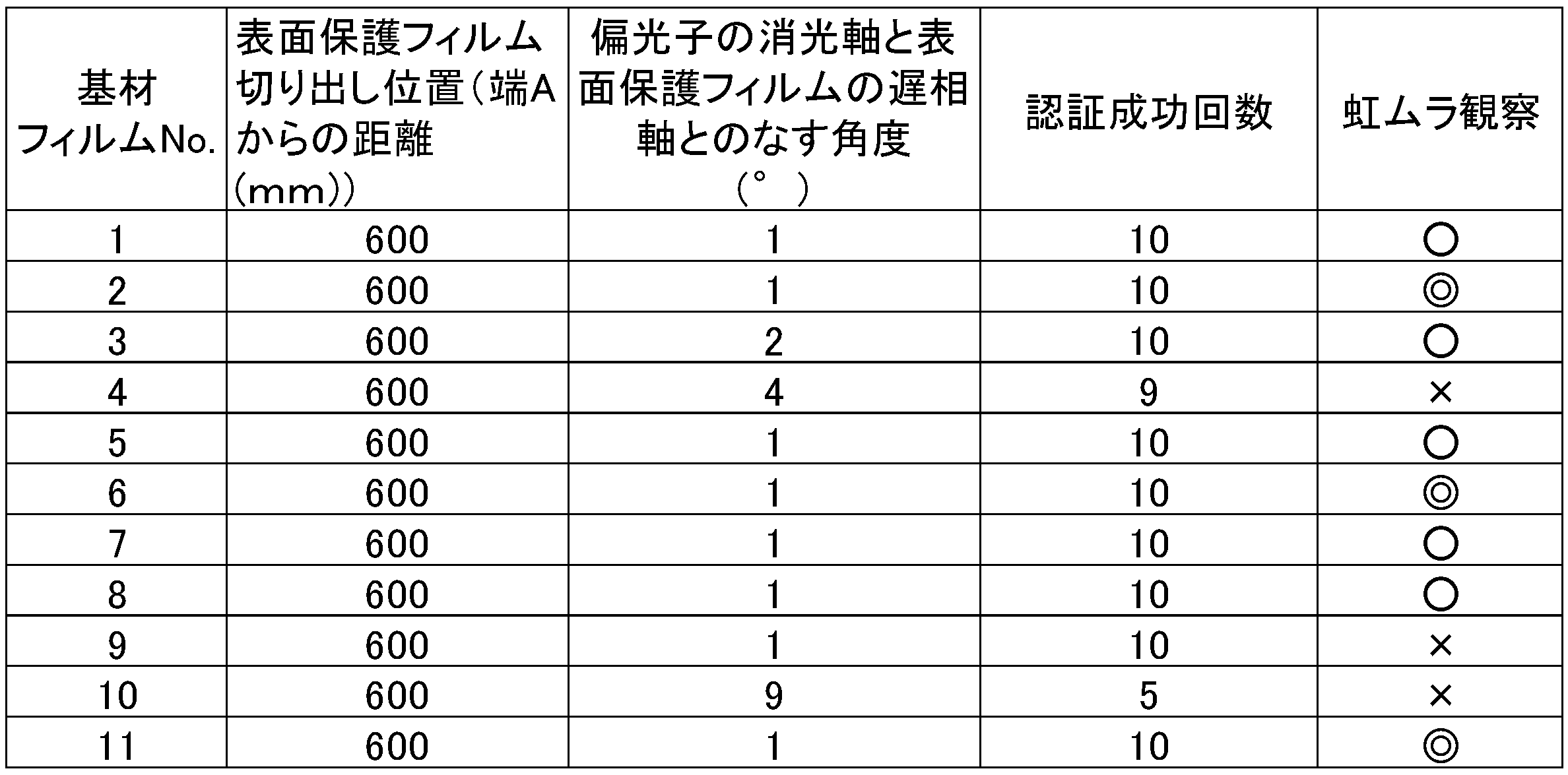
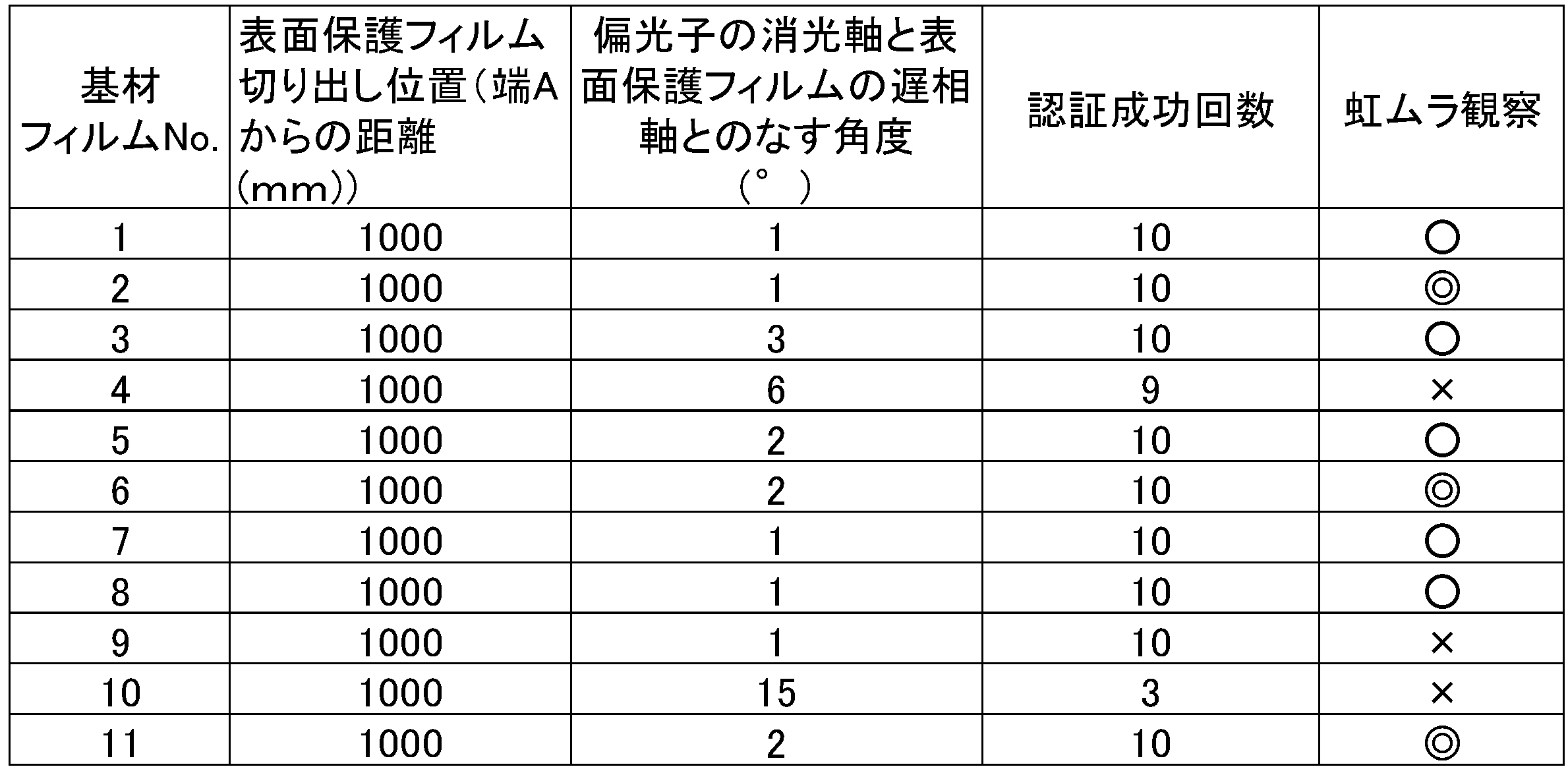
表2~4において、偏光子の消光軸と表面保護フィルムの遅相軸のなす角度は、正の数値は、偏光子の消光軸に対して遅相軸が視認側から見て右回り方向を示す。表2~4において示されるように、基材フィルムNo.1~9、11は、いずれも認証成功回数が高く、良好な指紋認証性を有していた。また、基材フィルムNo.2、6、11は虹ムラが認められず、No.1、3、5、7、8は弱い虹ムラは認められたものの、実用上の問題はなく、虹ムラ抑制効果が認められた。
1 画像表示装置
2 画像表示部
3 指紋認証センサー部
21 画像表示セル
22 偏光板
23 粘着剤層
24 表面保護フィルム
31 指紋認証センサー本体
2 画像表示部
3 指紋認証センサー部
21 画像表示セル
22 偏光板
23 粘着剤層
24 表面保護フィルム
31 指紋認証センサー本体
Claims (4)
- 下記(1)~(4)を満足する、指紋認証センサー付き画像表示装置の表面保護フィルム用基材フィルム。
(1)前記基材フィルムは、少なくとも片面に易接着層を有するポリエステルフィルムである
(2)前記基材フィルムは、遅相軸のバラツキが7°/m以下である
(3)前記基材フィルムは、3000~30000nmのレタデーションを有する
(4)前記基材フィルムは、Nz係数が2.5以下である - 前記ポリエステルフィルムが、ポリエチレンテレフタレートフィルムであって、ポリエチレンテレフタレートフィルムを構成する樹脂中には実質的に滑材を含まない、請求項1に記載の指紋認証センサー付き画像表示装置の表面保護フィルム用基材フィルム。
- 請求項1又は2に記載の基材フィルムの易接着層面に機能層が積層された、指紋認証センサー付き画像表示装置の表面保護フィルム。
- 指紋認証センサーの視認側に偏光板を有する画像表示装置であって、
前記偏光板より視認側に、請求項3に記載の表面保護フィルムを有し、
表面保護フィルムの遅相軸方向と前記偏光板の偏光子の消光軸方向がなす角度が0°±6°以下、または90°±6°以下である画像表示装置。
Priority Applications (3)
| Application Number | Priority Date | Filing Date | Title |
|---|---|---|---|
| CN202080013034.8A CN113412440B (zh) | 2019-05-31 | 2020-05-25 | 带指纹验证传感器的图像显示装置的表面保护薄膜用基材薄膜、表面保护薄膜和图像显示装置 |
| JP2020545737A JP7081676B2 (ja) | 2019-05-31 | 2020-05-25 | 指紋認証センサー付き画像表示装置の表面保護フィルム用基材フィルム、表面保護フィルムおよび画像表示装置 |
| KR1020217019594A KR102871082B1 (ko) | 2019-05-31 | 2020-05-25 | 지문 인증 센서 부착 화상 표시 장치의 표면 보호 필름용 기재 필름, 표면 보호 필름 및 화상 표시 장치 |
Applications Claiming Priority (2)
| Application Number | Priority Date | Filing Date | Title |
|---|---|---|---|
| JP2019102709 | 2019-05-31 | ||
| JP2019-102709 | 2019-05-31 |
Publications (2)
| Publication Number | Publication Date |
|---|---|
| WO2020241589A1 true WO2020241589A1 (ja) | 2020-12-03 |
| WO2020241589A9 WO2020241589A9 (ja) | 2021-01-21 |
Family
ID=73552632
Family Applications (1)
| Application Number | Title | Priority Date | Filing Date |
|---|---|---|---|
| PCT/JP2020/020595 Ceased WO2020241589A1 (ja) | 2019-05-31 | 2020-05-25 | 指紋認証センサー付き画像表示装置の表面保護フィルム用基材フィルム、表面保護フィルムおよび画像表示装置 |
Country Status (5)
| Country | Link |
|---|---|
| JP (1) | JP7081676B2 (ja) |
| KR (1) | KR102871082B1 (ja) |
| CN (1) | CN113412440B (ja) |
| TW (1) | TWI848119B (ja) |
| WO (1) | WO2020241589A1 (ja) |
Cited By (5)
| Publication number | Priority date | Publication date | Assignee | Title |
|---|---|---|---|---|
| WO2023000292A1 (zh) * | 2021-07-23 | 2023-01-26 | 京东方科技集团股份有限公司 | 偏光片、显示装置以及偏光片的制作方法 |
| WO2023027119A1 (ja) * | 2021-08-27 | 2023-03-02 | 住友化学株式会社 | 光学積層体 |
| JP7371808B1 (ja) | 2020-03-31 | 2023-10-31 | 大日本印刷株式会社 | 光学用のプラスチックフィルム、並びに、それを用いた光学積層体、偏光板及び画像表示装置 |
| JP7603182B1 (ja) | 2024-03-08 | 2024-12-19 | 株式会社トッパンTomoegawaオプティカルフィルム | 光学積層体及びこれを用いた表示装置 |
| JP2025137236A (ja) * | 2024-03-08 | 2025-09-19 | Toppan・Tomoegawaオプティカルフィルム株式会社 | 光学積層体及びこれを用いた表示装置 |
Families Citing this family (1)
| Publication number | Priority date | Publication date | Assignee | Title |
|---|---|---|---|---|
| KR20240061648A (ko) * | 2021-09-29 | 2024-05-08 | 도요보 가부시키가이샤 | 마이크로 led 화상 표시 장치 |
Citations (3)
| Publication number | Priority date | Publication date | Assignee | Title |
|---|---|---|---|---|
| WO2018159568A1 (ja) * | 2017-02-28 | 2018-09-07 | 東洋紡株式会社 | 液晶表示装置 |
| WO2018181055A1 (ja) * | 2017-03-31 | 2018-10-04 | 富士フイルム株式会社 | 有機半導体素子、有機半導体組成物、有機半導体膜の製造方法、有機半導体膜、並びに、これらに用いる化合物及びポリマー |
| JP2019049716A (ja) * | 2017-09-11 | 2019-03-28 | エルジー ディスプレイ カンパニー リミテッド | 表示装置とこれを含むモバイル情報端末 |
Family Cites Families (16)
| Publication number | Priority date | Publication date | Assignee | Title |
|---|---|---|---|---|
| JP2008224840A (ja) * | 2007-03-09 | 2008-09-25 | Fujifilm Corp | 偏光板および液晶表示装置 |
| JP5204629B2 (ja) * | 2007-11-29 | 2013-06-05 | 日東電工株式会社 | 偏光板、光学フィルムおよび画像表示装置 |
| JP2009300611A (ja) * | 2008-06-11 | 2009-12-24 | Nitto Denko Corp | 偏光板及び液晶パネル |
| CN103033984B (zh) * | 2011-09-30 | 2015-04-08 | 大日本印刷株式会社 | 液晶显示装置和偏振片保护膜 |
| JP6459159B2 (ja) * | 2013-02-15 | 2019-01-30 | 東洋紡株式会社 | 画像表示装置 |
| CN105468187A (zh) | 2014-06-18 | 2016-04-06 | 宸鸿科技(厦门)有限公司 | 具有指纹识别功能的触控面板 |
| KR101731676B1 (ko) * | 2014-07-23 | 2017-05-02 | 삼성에스디아이 주식회사 | 편광판 및 이를 포함하는 광학표시장치 |
| KR101813438B1 (ko) * | 2015-03-04 | 2018-01-30 | 도요보 가부시키가이샤 | 액정표시장치 |
| US9710689B2 (en) | 2015-10-30 | 2017-07-18 | Essential Products, Inc. | Fingerprint sensors for mobile devices |
| US20190113791A1 (en) * | 2016-02-09 | 2019-04-18 | Dai Nippon Printing Co., Ltd. | Optical laminate and production method therefor, front panel, and image display device |
| KR102187815B1 (ko) * | 2016-05-24 | 2020-12-08 | 후지필름 가부시키가이샤 | 적층체와 이를 갖는 화상 표시 장치의 전면판, 화상 표시 장치, 화상 표시 기능을 갖는 미러, 저항막식 터치 패널 및 정전 용량식 터치 패널 |
| KR102384014B1 (ko) * | 2017-03-14 | 2022-04-08 | 삼성전자주식회사 | 지문 검출 방법 및 이를 수행하는 전자 장치 |
| KR102343137B1 (ko) * | 2017-03-31 | 2021-12-24 | 도요보 가부시키가이샤 | 액정 표시 장치, 편광판 및 편광자 보호 필름 |
| KR102063201B1 (ko) * | 2017-05-18 | 2020-01-07 | 삼성에스디아이 주식회사 | 편광판 및 이를 포함하는 광학표시장치 |
| CN107748874B (zh) * | 2017-11-01 | 2020-12-04 | 京东方科技集团股份有限公司 | 全屏指纹识别oled模组、指纹识别方法及显示装置 |
| CN109036162B (zh) * | 2018-08-29 | 2021-06-29 | 上海天马有机发光显示技术有限公司 | 一种有机发光显示面板、制备方法和一种显示装置 |
-
2020
- 2020-05-25 CN CN202080013034.8A patent/CN113412440B/zh active Active
- 2020-05-25 KR KR1020217019594A patent/KR102871082B1/ko active Active
- 2020-05-25 WO PCT/JP2020/020595 patent/WO2020241589A1/ja not_active Ceased
- 2020-05-25 JP JP2020545737A patent/JP7081676B2/ja active Active
- 2020-05-29 TW TW109118009A patent/TWI848119B/zh active
Patent Citations (3)
| Publication number | Priority date | Publication date | Assignee | Title |
|---|---|---|---|---|
| WO2018159568A1 (ja) * | 2017-02-28 | 2018-09-07 | 東洋紡株式会社 | 液晶表示装置 |
| WO2018181055A1 (ja) * | 2017-03-31 | 2018-10-04 | 富士フイルム株式会社 | 有機半導体素子、有機半導体組成物、有機半導体膜の製造方法、有機半導体膜、並びに、これらに用いる化合物及びポリマー |
| JP2019049716A (ja) * | 2017-09-11 | 2019-03-28 | エルジー ディスプレイ カンパニー リミテッド | 表示装置とこれを含むモバイル情報端末 |
Cited By (16)
| Publication number | Priority date | Publication date | Assignee | Title |
|---|---|---|---|---|
| JP7371808B1 (ja) | 2020-03-31 | 2023-10-31 | 大日本印刷株式会社 | 光学用のプラスチックフィルム、並びに、それを用いた光学積層体、偏光板及び画像表示装置 |
| JP2023168344A (ja) * | 2020-03-31 | 2023-11-24 | 大日本印刷株式会社 | 光学用のプラスチックフィルム、並びに、それを用いた光学積層体、偏光板及び画像表示装置 |
| JP2023168345A (ja) * | 2020-03-31 | 2023-11-24 | 大日本印刷株式会社 | 光学用のプラスチックフィルム、並びに、それを用いた光学積層体、偏光板及び画像表示装置 |
| JP7371807B1 (ja) | 2020-03-31 | 2023-10-31 | 大日本印刷株式会社 | 光学用のプラスチックフィルム、並びに、それを用いた光学積層体、偏光板及び画像表示装置 |
| CN117348287A (zh) * | 2021-07-23 | 2024-01-05 | 京东方科技集团股份有限公司 | 偏光片以及显示装置 |
| CN115917420A (zh) * | 2021-07-23 | 2023-04-04 | 京东方科技集团股份有限公司 | 偏光片、显示装置以及偏光片的制作方法 |
| WO2023000292A1 (zh) * | 2021-07-23 | 2023-01-26 | 京东方科技集团股份有限公司 | 偏光片、显示装置以及偏光片的制作方法 |
| JP2023032450A (ja) * | 2021-08-27 | 2023-03-09 | 住友化学株式会社 | 光学積層体 |
| WO2023027119A1 (ja) * | 2021-08-27 | 2023-03-02 | 住友化学株式会社 | 光学積層体 |
| JP7603182B1 (ja) | 2024-03-08 | 2024-12-19 | 株式会社トッパンTomoegawaオプティカルフィルム | 光学積層体及びこれを用いた表示装置 |
| JP7719322B1 (ja) | 2024-03-08 | 2025-08-05 | Toppan・Tomoegawaオプティカルフィルム株式会社 | 光学積層体及びこれを用いた表示装置 |
| JP7719273B1 (ja) | 2024-03-08 | 2025-08-05 | Toppan・Tomoegawaオプティカルフィルム株式会社 | 光学積層体及びこれを用いた表示装置 |
| JP2025137363A (ja) * | 2024-03-08 | 2025-09-19 | Toppan・Tomoegawaオプティカルフィルム株式会社 | 光学積層体及びこれを用いた表示装置 |
| JP2025137236A (ja) * | 2024-03-08 | 2025-09-19 | Toppan・Tomoegawaオプティカルフィルム株式会社 | 光学積層体及びこれを用いた表示装置 |
| JP2025137499A (ja) * | 2024-03-08 | 2025-09-19 | Toppan・Tomoegawaオプティカルフィルム株式会社 | 光学積層体及びこれを用いた表示装置 |
| JP2025137237A (ja) * | 2024-03-08 | 2025-09-19 | Toppan・Tomoegawaオプティカルフィルム株式会社 | 光学積層体及びこれを用いた表示装置 |
Also Published As
| Publication number | Publication date |
|---|---|
| CN113412440A (zh) | 2021-09-17 |
| JP7081676B2 (ja) | 2022-06-07 |
| TW202104937A (zh) | 2021-02-01 |
| KR20220013350A (ko) | 2022-02-04 |
| TWI848119B (zh) | 2024-07-11 |
| WO2020241589A9 (ja) | 2021-01-21 |
| KR102871082B1 (ko) | 2025-10-15 |
| JPWO2020241589A1 (ja) | 2021-09-13 |
| CN113412440B (zh) | 2024-01-02 |
Similar Documents
| Publication | Publication Date | Title |
|---|---|---|
| JP7081676B2 (ja) | 指紋認証センサー付き画像表示装置の表面保護フィルム用基材フィルム、表面保護フィルムおよび画像表示装置 | |
| US11934226B2 (en) | Foldable display and portable terminal device | |
| TWI557447B (zh) | Liquid crystal display device, polarizing plate and polarizer protective film | |
| JP6863530B2 (ja) | 指紋認証センサー付き画像表示装置 | |
| WO2020162119A1 (ja) | ポリエステルフィルムとその用途 | |
| JP2009509179A (ja) | 多層反射偏光子の製造方法 | |
| JP7768214B2 (ja) | 配向フィルム、これを用いた画像表示装置、及び、枚葉の配向フィルムの切り出し方法 | |
| JP2009012254A (ja) | 離型フィルム | |
| JP2001290141A (ja) | 離型フィルム | |
| KR100689974B1 (ko) | 이형 필름 | |
| CN116529638A (zh) | 光学膜、偏光板、图像显示装置以及光学膜的选定方法 | |
| JP2004177719A (ja) | 離型フィルム | |
| JP4521704B2 (ja) | 離型フィルム | |
| WO2023167263A1 (ja) | 易接着層付きポリエステルフィルム、前記ポリエステルフィルムを備えた光学積層体、並びに、前記光学積層体を備えた偏光板、表面板、画像表示パネル及び画像表示装置 | |
| TWI908787B (zh) | 光學積層體、以及具備其之偏光板、表面板及影像顯示裝置 | |
| EP3170660B1 (en) | Uniaxially stretched multilayer laminate film, and optical member comprising same | |
| TW202200685A (zh) | 偏光鏡保護用聚酯薄膜、偏光板及液晶顯示裝置 | |
| JP2004177718A (ja) | 離型フィルム | |
| JP4397499B2 (ja) | 液晶偏光板粘着層保護用離型フィルム | |
| JP2004299344A (ja) | 離型フィルム | |
| JP2014052596A (ja) | 集光機能フィルム並びにこれを用いた偏光板及び液晶表示装置 | |
| JP6441147B2 (ja) | 延伸多層積層反射ポリエステルフィルムおよびそれからなる液晶ディスプレイ装置 | |
| JP7338359B2 (ja) | 光学用ポリエステルフィルムロール | |
| JP2019073598A (ja) | フィルムおよび導電フィルム | |
| JP2012027294A (ja) | 偏光板基材用ポリエステルフィルム |
Legal Events
| Date | Code | Title | Description |
|---|---|---|---|
| ENP | Entry into the national phase |
Ref document number: 2020545737 Country of ref document: JP Kind code of ref document: A |
|
| 121 | Ep: the epo has been informed by wipo that ep was designated in this application |
Ref document number: 20813819 Country of ref document: EP Kind code of ref document: A1 |
|
| NENP | Non-entry into the national phase |
Ref country code: DE |
|
| 122 | Ep: pct application non-entry in european phase |
Ref document number: 20813819 Country of ref document: EP Kind code of ref document: A1 |