WO2020240634A1 - 防音放熱材、防音放熱材付き機器及び部材 - Google Patents
防音放熱材、防音放熱材付き機器及び部材 Download PDFInfo
- Publication number
- WO2020240634A1 WO2020240634A1 PCT/JP2019/020772 JP2019020772W WO2020240634A1 WO 2020240634 A1 WO2020240634 A1 WO 2020240634A1 JP 2019020772 W JP2019020772 W JP 2019020772W WO 2020240634 A1 WO2020240634 A1 WO 2020240634A1
- Authority
- WO
- WIPO (PCT)
- Prior art keywords
- soundproofing
- heat radiating
- heat
- soundproof
- radiating
- Prior art date
- Legal status (The legal status is an assumption and is not a legal conclusion. Google has not performed a legal analysis and makes no representation as to the accuracy of the status listed.)
- Ceased
Links
Images





Classifications
-
- G—PHYSICS
- G10—MUSICAL INSTRUMENTS; ACOUSTICS
- G10K—SOUND-PRODUCING DEVICES; METHODS OR DEVICES FOR PROTECTING AGAINST, OR FOR DAMPING, NOISE OR OTHER ACOUSTIC WAVES IN GENERAL; ACOUSTICS NOT OTHERWISE PROVIDED FOR
- G10K11/00—Methods or devices for transmitting, conducting or directing sound in general; Methods or devices for protecting against, or for damping, noise or other acoustic waves in general
- G10K11/16—Methods or devices for protecting against, or for damping, noise or other acoustic waves in general
- G10K11/162—Selection of materials
-
- G—PHYSICS
- G10—MUSICAL INSTRUMENTS; ACOUSTICS
- G10K—SOUND-PRODUCING DEVICES; METHODS OR DEVICES FOR PROTECTING AGAINST, OR FOR DAMPING, NOISE OR OTHER ACOUSTIC WAVES IN GENERAL; ACOUSTICS NOT OTHERWISE PROVIDED FOR
- G10K11/00—Methods or devices for transmitting, conducting or directing sound in general; Methods or devices for protecting against, or for damping, noise or other acoustic waves in general
- G10K11/16—Methods or devices for protecting against, or for damping, noise or other acoustic waves in general
- G10K11/162—Selection of materials
- G10K11/168—Plural layers of different materials, e.g. sandwiches
Definitions
- the present invention relates to a soundproof heat radiating material, a device and a member with a soundproof heat radiating material.
- the soundproofing member include a member provided with a urethane foam layer, an airgel layer, a cotton-like mixed glass long fiber, a fiber layer composed of at least one of an organic long fiber and an inorganic long fiber, and the like.
- a soundproofing member having excellent soundproofing and heat dissipation a phenol hard foam having a communicating bubble structure is pressed and filled into a cell of an aluminum honeycomb material to form a core layer material, and sound is produced on one surface of the core layer material.
- a honeycomb panel body is proposed in which a breathable surface material that allows heat to pass through is attached to another surface with a plate material that reflects sound but allows heat to pass through (see, for example, Patent Document 1).
- the soundproofing member When a soundproofing member such as a sound insulating member or a sound absorbing member is directly placed on a noise source having a curved surface, an uneven surface, etc., the soundproofing member must have the property of deforming according to the shape of the noise source (shapeability).
- a soundproofing member such as the honeycomb panel body disclosed in Patent Document 1 has insufficient shapeability, a gap is likely to occur between the noise source and the soundproofing member, the heat dissipation is lowered, or the soundproofing member is provided. The space required for installation may increase. Further, even in applications other than soundproofing, a member having excellent heat dissipation and shapeability is required.
- a soundproof heat radiating material including a plurality of soundproof heat radiating units including a soundproofing material and a foil-shaped heat radiating member arranged around the soundproofing material.
- ⁇ 5> The soundproofing / radiating material according to any one of ⁇ 1> to ⁇ 4>, wherein the plurality of soundproofing / radiating units include soundproofing / radiating units of different sizes.
- ⁇ 6> The soundproof heat radiating material according to any one of ⁇ 1> to ⁇ 5>, wherein the heat radiating member is a metal foil.
- ⁇ 7> The soundproof heat radiating material according to any one of ⁇ 1> to ⁇ 6>, wherein the heat radiating member contains at least one metal selected from the group consisting of aluminum, iron, copper and an alloy containing these.
- ⁇ 8> The soundproof heat radiating material according to any one of ⁇ 1> to ⁇ 7>, wherein the heat radiating member has a thickness of 0.005 mm to 0.200 mm.
- ⁇ 9> The soundproof heat dissipation according to any one of ⁇ 1> to ⁇ 8>, wherein the heat dissipation member forms a continuous heat transfer path from one main surface of the soundproof heat dissipation material to the other main surface.
- Material. ⁇ 10> The soundproofing and heat radiating material according to ⁇ 9>, wherein when there are a plurality of the heat transfer paths, the distance between the adjacent heat transfer paths is 30 mm or less.
- one main surface of the soundproofing heat radiating material is a surface on the device side that emits noise and heat, and the other main surface is a surface on the heat radiating side.
- ⁇ 12> The soundproofing and radiating material according to any one of ⁇ 1> to ⁇ 11>, further including a soundproofing material in which a foil-shaped heat radiating member is not arranged around.
- ⁇ 13> The soundproofing / radiating material according to any one of ⁇ 1> to ⁇ 12>, further comprising a soundproofing case for accommodating the plurality of soundproofing / radiating units.
- a soundproof heat dissipation unit including a soundproof material and a foil-shaped heat dissipation member arranged around the soundproof material.
- the soundproofing and heat radiating unit according to ⁇ 14> which is used by being attached to a device that emits noise and heat.
- a soundproof heat radiating material including the soundproof heat radiating material according to any one of ⁇ 1> to ⁇ 13>, the soundproof heat radiating unit according to ⁇ 14> or ⁇ 15>, and a device that emits noise and heat. With equipment.
- a member including a plurality of units including a porous and flexible or elastic object and a heat-conducting foil-like object arranged around the object.
- a soundproof heat radiating material having excellent heat dissipation, soundproofing and shapeability, and a device with a soundproofing heat radiating material provided with the soundproof heat radiating material. According to the present disclosure, it is possible to provide a member having excellent heat dissipation and shapeability.
- the present invention is not limited to the following embodiments.
- the components including element steps and the like are not essential unless otherwise specified.
- the numerical range indicated by using "-" includes the numerical values before and after "-" as the minimum value and the maximum value, respectively.
- the upper limit value or the lower limit value described in one numerical range may be replaced with the upper limit value or the lower limit value of another numerical range described stepwise. ..
- soundproofing includes “soundproofing” and “sound absorbing”, and “soundproofing and heat radiating material” may be appropriately read as “soundproofing and radiating material” or “sound absorbing and radiating material”.
- porous means having a plurality of pores such as communication holes, closed pores, and open pores.
- flexibility means the property of deforming when a force is applied to an object
- elasticity means the property of deforming when a force is applied to an object and returning to the original state when the force is removed.
- the soundproofing heat radiating material of the present disclosure includes a plurality of soundproofing and radiating units including a soundproofing material and a foil-shaped heat radiating member arranged around the soundproofing material.
- the soundproofing and heat radiating material of the present disclosure exhibits excellent soundproofing due to the soundproofing material contained in the plurality of soundproofing and radiating units.
- the heat radiating member arranged around the soundproofing material suppresses the accumulation of heat inside the soundproofing and radiating material, and has excellent heat dissipation.
- the soundproofing and heat radiating material of the present disclosure is composed of a plurality of soundproofing and heat radiating units. Therefore, it is easier to obtain a shape corresponding to the shape of the device to which the soundproof heat radiating material is attached (excellent in shapeability) as compared with the case where the entire soundproofing heat radiating material is composed of one member.
- the soundproofing heat radiating material of the present disclosure is arranged so as to come into contact with, for example, a device that emits noise and heat directly or via another member, reduces the noise level emitted from the device, and transmits the generated heat to the outside. It is used to dissipate heat. Since the soundproofing and heat radiating material of the present disclosure has excellent formability, it can be installed in a device that emits noise and heat without wasting space, suppresses a temperature rise of the above-mentioned device, and is from the above-mentioned device. Noise can be suppressed. As a result, the soundproofing and heat radiating material of the present disclosure can be preferably used in equipment such as compressors.
- one surface (main surface A) of the soundproof and heat radiating material is the surface on the device side that emits noise and heat
- the other surface (main surface B) is the heat radiating side.
- the heat generated on the main surface A side may be transferred to the main surface B side to dissipate heat.
- a heat transfer path continuous from the main surface A to the main surface B of the soundproofing and radiating material is formed by the heat radiating member arranged around the soundproofing material constituting the soundproofing and radiating unit. Through this heat transfer path, heat is efficiently transferred from the main surface A side to the main surface B side, and excellent heat dissipation is achieved.
- the "heat transfer path” means a heat transfer path having higher heat transfer property than the soundproof material, which is formed by the continuous existence of the heat dissipation member from the main surface A to the main surface B of the soundproof material. To do.
- the thickness of the soundproofing heat radiating material (excluding the thickness of the soundproofing case described later) is not particularly limited, and can be adjusted according to the application of the soundproofing heat radiating material. For example, it may be 1 mm to 50 mm, 3 mm to 30 mm, or 5 mm to 20 mm.
- the area of the main surface of the soundproof heat radiating material is not particularly limited and can be adjusted according to the application of the soundproof heat radiating material. For example, it may be a 10cm 2 ⁇ 10,000cm 2.
- the soundproofing and heat radiating material of the present disclosure includes a plurality of soundproofing and heat radiating units.
- the number of soundproof and heat radiating units is not particularly limited, and can be selected according to the size and shape of the soundproof and heat radiating material. From the viewpoint of exhibiting excellent soundproofing and heat dissipation, it is preferable that the plurality of soundproofing and heat radiating units are closely arranged. From the viewpoint of closely arranging a plurality of soundproof and heat radiating units, the soundproof and heat radiating unit is preferably an object having a quadrangular cross section.
- the cross-sectional shape of the soundproof heat dissipation unit may be deformed.
- the cross-sectional shape of the soundproofing and heat radiating unit may be a shape other than a quadrangle (for example, a substantially circular shape).
- the soundproofing and heat-dissipating material of the present disclosure is composed only of a soundproofing material (soundproofing and heat-dissipating unit) in which heat-dissipating members are arranged around it, the soundproofing material (heat-dissipating area) in which heat-dissipating members are arranged around and a heat-dissipating member around it. It may be a combination with a soundproofing material (non-heat dissipation area) in which is not arranged.
- the material of the soundproofing material is not particularly limited as long as it has a soundproofing effect such as a soundproofing effect and a sound absorbing effect.
- the soundproofing material may be porous.
- Porous materials include resins such as urethane resin, phenol resin, polystyrene resin, polypropylene resin, and polyethylene resin, foams obtained by foaming synthetic rubber, aerogels such as silica, and cotton-like long glass fibers. Examples thereof include fibers composed of at least one of organic long fibers and inorganic long fibers.
- the soundproofing material is preferably flexible or elastic.
- the soundproofing material has flexibility or elasticity, it is easily deformed according to the shape of the device to which the soundproofing and heat radiating material is attached, and a state in close contact with the device can be easily obtained.
- the soundproofing material has elasticity, a repulsive force is generated in the deformed soundproofing material, and it is easy to maintain a state of being in close contact with the surface of the device.
- the size or shape of the soundproofing and heat radiating unit may be the same or different. By combining soundproof and heat radiating units of different sizes or shapes, the shape can be made to correspond to the shape of the device to which the soundproof and heat radiating material is attached.
- each soundproofing and radiating unit is not particularly limited and can be adjusted according to the application of the soundproofing and radiating material. For example, it may be 1 mm to 50 mm, 3 mm to 30 mm, or 5 mm to 20 mm.
- the soundproofing heat radiating material of the present disclosure includes a foil-shaped heat radiating member arranged around the soundproofing material. From the viewpoint of ease of arranging the soundproofing material around, it is preferable that the heat radiating member is easily deformed.
- the heat radiating member may be, for example, a metal foil.
- the heat radiating member is not particularly limited as long as it has heat transfer properties, and may be, for example, a member containing metal.
- the member containing metal may be a member made of only metal, or the surface of a non-metal member such as fiber or resin may be coated with metal, or the surface of metal may be coated with another metal. You may.
- the shape of the heat radiating member is not particularly limited as long as it is foil-shaped, and may be sheet-shaped, tape-shaped, or the like.
- the surface shape of the heat radiating member is not particularly limited, and may be mirror-shaped, may have irregularities, or may be a combination of these.
- the heat radiating member contains a metal
- it preferably contains at least one metal selected from the group consisting of aluminum, iron, copper and alloys containing these (stainless steel, etc.), and from the viewpoint of heat transfer, aluminum, copper and these. More preferably, it contains at least one metal selected from the group consisting of alloys containing.
- the thickness of the heat radiating member is preferably 0.005 mm or more, more preferably 0.01 mm or more, further preferably 0.02 mm or more, and 0. It is particularly preferable that it is .03 mm or more. Further, the thickness of the heat radiating member is preferably 0.200 mm or less, more preferably 0.100 mm or less, further preferably 0.080 mm or less, and 0, from the viewpoint of easiness of deformation. It is particularly preferably .050 mm or less.
- the thickness of the heat radiating member changes depending on the position, it is preferable that the numerical range of the above-mentioned thickness is satisfied at at least one place, 0.005 mm or more is satisfied at the position where the thickness is the smallest, and the thickness is the largest. It is more preferable to satisfy 0.200 mm or less at the position where it becomes large.
- the heat radiating member may consist of only one heat radiating member or may be a stack of a plurality of heat radiating members.
- the heat radiating member is a stack of a plurality of heat radiating members, it is preferable that the total thickness of the plurality of heat radiating members satisfies the above-mentioned numerical range of thickness.
- the mode in which the heat radiating member is arranged around the soundproofing material is not particularly limited as long as a continuous heat transfer path is formed from the main surface A to the main surface B of the soundproofing radiating member.
- the heat radiating member may be wound around the soundproofing material.
- the heat radiating member may be arranged so as to cover the entire surface of the soundproofing material, or may be arranged so as to partially cover the surface of the soundproofing material (there is a portion not covered by the heat radiating member).
- the heat radiating member may be arranged so that the heat radiating member overlaps the entire surface or a part of the surface of the soundproofing material.
- the position where the heat radiating members overlap is not particularly limited, and may be on the surface or inside of the soundproofing heat radiating material.
- the distance between adjacent heat transfer paths is not particularly limited. For example, it may be 30 mm or less, 20 mm or less, or 10 mm or less.
- the lower limit of the distance between the heat transfer paths is not particularly limited, and may be, for example, 1 mm or more.
- the soundproof heat radiating material may include a heat radiating auxiliary member arranged on at least one of the main surface A and the main surface B, preferably in contact with the end of the heat transfer path formed of the heat radiating member.
- the heat dissipation assisting member is not particularly limited as long as it has heat transfer properties, and examples thereof include members containing metal.
- the shape of the heat dissipation assisting member is not particularly limited, and may be, for example, a foil shape.
- the soundproof heat radiating material may further include a soundproof case accommodating a plurality of soundproof heat radiating units.
- a soundproof case accommodating a plurality of soundproof heat radiating units.
- the material of the soundproof case is not particularly limited and can be selected in consideration of the balance between soundproofing and heat dissipation.
- metal is preferable from the viewpoint of heat dissipation
- resin is preferable from the viewpoint of weight reduction.
- the soundproof case may be composed of two or more kinds of materials.
- the portion of the soundproofing heat radiating material corresponding to the heat radiating side surface (main surface B) may be made of metal, and the portion of the soundproofing radiating material in contact with the device may be made of resin.
- the metal constituting the soundproof case include copper, iron, aluminum, magnesium, and alloys thereof (stainless steel, etc.).
- the resin include polypropylene, nylon, polycarbonate and the like.
- the soundproofing case has a shape that covers all surfaces other than the surface (main surface A) on the device side that emits noise and heat of the soundproofing and heat radiating material. Further, it is preferable that the soundproofing material and the soundproofing case are in close contact with each other, at least in the thickness direction of the soundproofing and heat radiating material.
- the soundproofing case has a shape that does not cover the surface (main surface A) of the soundproofing and heat radiating material on the device side that emits noise and heat.
- the soundproof case is preferably more rigid (harder to deform) than the soundproof heat dissipation unit from the viewpoint of supporting and protecting the soundproof heat dissipation unit. Further, the soundproof case may be provided with screw holes or the like so that the soundproof heat radiating material and the device that generates noise and heat can be fixed.
- the soundproofing and heat radiating material of the present disclosure is not limited to the following specific examples, and the configurations of these specific examples may be combined as necessary.
- the "vertically lower surface” may be read as “main surface A”
- the "vertically upper surface” may be read as “main surface B”.
- the vertical direction corresponds to the thickness direction of the soundproofing and heat radiating material.
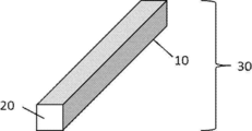
- FIG. 1 shows a schematic view of a specific example of the soundproofing material 20 constituting the soundproofing and radiating unit and the foil-shaped heat radiating member 10 arranged around the soundproofing material 20.
- FIG. 2 shows a schematic view of a specific example of the soundproof heat dissipation unit 30 in which the heat dissipation member 10 is arranged around the soundproof material 20.
- a continuous heat transfer path is formed by the heat radiating member 10 from the vertically lower surface to the vertically upper surface.
- FIG. 3 shows a schematic view of a specific example 1 of the soundproofing and heat radiating material.
- the soundproofing / radiating material 40 is configured so that the main surface is substantially flat by combining a plurality of soundproofing / radiating units 30 of the same size.
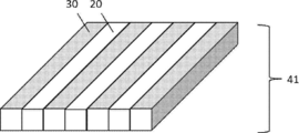
- FIG. 4 shows a schematic view of a specific example 2 of the soundproofing and heat radiating material.
- the main surface of the soundproofing heat radiating material 41 is formed by a combination of the soundproofing heat radiating unit 30 in which the heat radiating member is arranged around the soundproofing material and the soundproofing material 20 in which the heat radiating member is not arranged around the soundproofing material. It is configured to be substantially flat.
- FIG. 5 shows a schematic view of a specific example 3 of the soundproofing and heat radiating material.
- the soundproofing / radiating material 42 has a recess formed on one main surface by a combination of a plurality of soundproofing / radiating units 30, 31, and 32 having different sizes in the thickness direction.
- the shape is such that it is easy to follow the shape of the device that emits noise and heat to which the soundproofing and heat radiating material is attached.
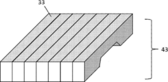
- FIG. 6 shows a schematic view of a specific example 4 of the soundproofing and heat radiating material.
- the soundproofing heat radiating material 43 shown in FIG. 6 has a concave portion formed on one main surface by a combination of a plurality of soundproofing heat radiating units 33 of the same size provided with a concave portion on the vertically lower surface.
- FIG. 7 shows a schematic view of a specific example 5 of the soundproofing and heat radiating material.
- the soundproof heat radiating material 44 shown in FIG. 7 is provided with a recess on the vertically lower surface, and a recess is formed on one of the main surfaces by combining a plurality of soundproof heat radiating units 34, 35, 36 having different sizes in the thickness direction. Has been done.
- the shape is such that it can easily follow the shape of the device that emits noise and heat, which has a three-dimensionally complicated shape.
- FIG. 8 shows a schematic view (cross-sectional view) of a specific example 6 of the soundproof heat radiating material.
- the soundproofing heat radiating material 45 shown in FIG. 8 includes a soundproofing case 50 accommodating a plurality of soundproofing heat radiating units 30.
- the soundproof case 50 shown in FIG. 8 has a shape that covers a surface other than the vertically lower surface of the soundproof heat radiating material 45.
- the thickness direction of the soundproof and heat radiating unit 30 is larger than the thickness direction of the portion of the soundproof case 50 that houses the soundproof and heat radiating unit 30.
- the soundproofing and heat radiating unit of the present disclosure includes a soundproofing material and a linear heat radiating member arranged around the soundproofing material.
- a soundproofing material and a linear heat radiating member arranged around the soundproofing material.
- the details and preferred embodiments of the soundproofing and radiating unit used for the above-mentioned soundproofing and radiating material and the soundproofing material and heat radiating member used therein can be referred to. ..
- the soundproof and heat radiating unit of the present disclosure is excellent in heat dissipation, soundproofing and shaping.
- the soundproofing and heat radiating unit of the present disclosure By attaching the soundproofing and heat radiating unit of the present disclosure to a device that generates noise and heat, the noise emitted from the device can be effectively reduced and the temperature rise can be suppressed.
- the soundproofing and heat radiating unit is used as part of the soundproofing and heat radiating material described above.
- the device with the soundproofing and heat radiating material of the present disclosure includes the above-mentioned soundproofing and heat radiating material of the present disclosure and a device that emits noise and heat.
- the sound-proof and heat-dissipating material of the present disclosure can be installed in the equipment that emits noise and heat without wasting space, and the temperature rise of the above-mentioned equipment can be suppressed and the above-mentioned equipment can be suppressed. Noise from equipment can be suppressed.
- the soundproofing and heat radiating material and the device that emits noise and heat may be arranged so as to be in direct contact with each other, and other members (preferably members having excellent heat transfer properties) may be used. It may be arranged through.
- the members of the present disclosure include a plurality of units including a porous and flexible or elastic object and a heat-conducting foil-like object arranged around the object.
- the member having the above structure includes an object having porousness and flexibility or elasticity, it is easily deformed by following a surface having a three-dimensionally complicated shape (excellent in shapeability). Further, since a foil-like object having heat transfer property is included around this object, a continuous heat transfer path is formed from the main surface of the member to another main surface, and the heat dissipation is excellent.
- the members of the present disclosure are applicable not only to soundproofing applications such as sound insulation and sound absorption, but also to applications requiring heat dissipation and shape.
- the details and preferred embodiments of the soundproofing material described above can be referred to for the details and preferred embodiments of the flexible or elastic object, and the details and preferred embodiments of the heat-conducting foil-like object can be referred to.
- the details and preferred embodiments of the heat dissipation member described above can be referred to.
- Example 1 As the soundproofing material, a polyurethane foam having flexibility and elasticity of width 10 mm ⁇ length 50 mm ⁇ thickness 20 mm was used. A copper foil having a thickness of 0.020 mm was wound around this soundproof material as shown in FIG. 2 to prepare a soundproof heat dissipation unit. The soundproof and heat radiating units (5 pieces) were arranged side by side in a stainless steel case having a thickness of 0.1 mm to prepare a soundproof and heat radiating material.
- Example 2 As the soundproofing material, a polyurethane foam having flexibility and elasticity of width 10 mm ⁇ length 50 mm ⁇ thickness 20 mm was used. A copper foil having a thickness of 0.020 mm was wound around this soundproof material as shown in FIG. 2 to prepare a soundproof heat dissipation unit. The soundproofing and radiating unit (3 pieces) and the soundproofing material (2 pieces) not wrapped with copper foil were alternately arranged in a stainless steel case having a thickness of 0.1 mm to prepare a soundproofing and radiating material.
- Example 3 As the soundproofing material, a polyurethane foam having flexibility and elasticity of width 10 mm ⁇ length 50 mm ⁇ thickness 10 mm to 20 mm was used. A copper foil having a thickness of 0.020 mm was wound around this soundproofing material as shown in FIG. 2 to produce soundproofing and heat radiating units having different thicknesses. The soundproofing and radiating units (5 pieces) were arranged in a stainless steel case having a thickness of 0.1 mm in the order of thickness so that the soundproofing material having the smallest thickness was in the center to prepare the soundproofing and radiating material.
- the surface temperature of the stainless steel case is higher than that in the second embodiment in which the copper foil is not wrapped around some of the soundproofing materials, and the heat dissipation property. Turned out to be excellent.
- Heat dissipation member 20 Soundproof material 30, 31, 32, 33, 34, 35, 36 Soundproof heat dissipation unit 40, 41, 42, 43, 44, 45 Soundproof heat dissipation material 50 Soundproof case
Landscapes
- Physics & Mathematics (AREA)
- Engineering & Computer Science (AREA)
- Acoustics & Sound (AREA)
- Multimedia (AREA)
- Soundproofing, Sound Blocking, And Sound Damping (AREA)
- Building Environments (AREA)
Abstract
防音材と、前記防音材の周囲に配置される箔状の放熱部材と、を備える複数の防音放熱ユニットを含む、防音放熱材。
Description
本発明は、防音放熱材、防音放熱材付き機器及び部材に関する。
コンプレッサ等の騒音源を有する機械装置では、騒音対策のため、騒音源に防音部材を配置して騒音を低減することが考えられる。防音部材としては、発泡ウレタン層、エアロゲル層、綿状に混合されたガラス長繊維、有機の長繊維及び無機の長繊維の少なくとも一つからなる繊維層等を備える部材が挙げられる。
しかしながら、防音部材は断熱性を有しているため、騒音源に防音部材を配置した場合に放熱が阻害される。ここで、防音性及び放熱性に優れる防音部材として、アルミニウム製ハニカム材のセルに連通気泡構造を有するフェノール硬質発泡体を押込み充填して芯層材を形成し、該芯層材の一面に音と熱を通過させる通気性表面材を、他の面に音を反射するが熱を通過させる板材を接着剤で貼りつけてなるハニカムパネル体が提案されている(例えば、特許文献1参照)。
曲面、凹凸面等を有する騒音源に遮音部材、吸音部材等の防音部材を直接配置する場合、防音部材を騒音源の形状に追従して変形する性質(賦形性)が必要になる。例えば、特許文献1に開示のハニカムパネル体のような防音部材では賦形性が不十分であり、騒音源と防音部材との間に隙間が生じやすく、放熱性が低下したり、防音部材の設置に必要な空間が大きくなるおそれがある。また、防音以外の用途においても、放熱性及び賦形性に優れた部材が求められている。
本開示は上記課題に鑑みてなされたものであり、放熱性、防音性及び賦形性に優れる防音放熱材、並びにこれを備える防音放熱材付き機器を提供することを目的とする。
また、本開示は、放熱性及び賦形性に優れる部材を提供することを目的とする。
また、本開示は、放熱性及び賦形性に優れる部材を提供することを目的とする。
前記課題を達成するための具体的手段は以下の通りである。
<1>防音材と、前記防音材の周囲に配置される箔状の放熱部材と、を備える複数の防音放熱ユニットを含む、防音放熱材。
<2>前記放熱部材は前記防音材の周囲に巻き回されている、<1>に記載の防音放熱材。
<3>前記防音材は多孔質である、<1>又は<2>に記載の防音放熱材。
<4>前記防音材は柔軟性又は弾性を有する、<1>~<3>のいずれか1項に記載の防音放熱材。
<5>前記複数の防音放熱ユニットはサイズの異なる防音放熱ユニットを含む、<1>~<4>のいずれか1項に記載の防音放熱材。
<6>前記放熱部材は金属箔である、<1>~<5>のいずれか1項に記載の防音放熱材。
<7>前記放熱部材はアルミニウム、鉄、銅及びこれらを含む合金からなる群より選択される少なくとも一つの金属を含む、<1>~<6>のいずれか1項に記載の防音放熱材。
<8>前記放熱部材の厚さは0.005mm~0.200mmである、<1>~<7>のいずれか1項に記載の防音放熱材。
<9>前記放熱部材は前記防音放熱材の一方の主面から他方の主面まで連続する伝熱パスを形成している、<1>~<8>のいずれか1項に記載の防音放熱材。
<10>前記伝熱パスが複数存在する場合、隣り合う前記伝熱パス間の距離は30mm以下である、<9>に記載の防音放熱材。
<11>前記防音放熱材の一方の主面が騒音及び熱を発する機器側の面であり、他方の主面が放熱側の面である、<1>~<10>のいずれか1項に記載の防音放熱材。
<12>箔状の放熱部材が周囲に配置されていない防音材をさらに含む、<1>~<11>のいずれか1項に記載の防音放熱材。
<13>前記複数の防音放熱ユニットを収容する防音ケースをさらに備える、<1>~<12>のいずれか1項に記載の防音放熱材。
<14>防音材と、前記防音材の周囲に配置される箔状の放熱部材と、を備える防音放熱ユニット。
<15>騒音及び熱を発する機器に取り付けて使用される、<14>に記載の防音放熱ユニット。
<16><1>~<13>のいずれか1項に記載の防音放熱材又は<14>もしくは<15>に記載の防音放熱ユニットと、騒音及び熱を発する機器と、を備える防音放熱材付き機器。
<17>多孔質かつ柔軟性又は弾性を有する物体と、前記物体の周囲に配置される伝熱性を有する箔状の物体と、を備える複数のユニットを含む、部材。
<1>防音材と、前記防音材の周囲に配置される箔状の放熱部材と、を備える複数の防音放熱ユニットを含む、防音放熱材。
<2>前記放熱部材は前記防音材の周囲に巻き回されている、<1>に記載の防音放熱材。
<3>前記防音材は多孔質である、<1>又は<2>に記載の防音放熱材。
<4>前記防音材は柔軟性又は弾性を有する、<1>~<3>のいずれか1項に記載の防音放熱材。
<5>前記複数の防音放熱ユニットはサイズの異なる防音放熱ユニットを含む、<1>~<4>のいずれか1項に記載の防音放熱材。
<6>前記放熱部材は金属箔である、<1>~<5>のいずれか1項に記載の防音放熱材。
<7>前記放熱部材はアルミニウム、鉄、銅及びこれらを含む合金からなる群より選択される少なくとも一つの金属を含む、<1>~<6>のいずれか1項に記載の防音放熱材。
<8>前記放熱部材の厚さは0.005mm~0.200mmである、<1>~<7>のいずれか1項に記載の防音放熱材。
<9>前記放熱部材は前記防音放熱材の一方の主面から他方の主面まで連続する伝熱パスを形成している、<1>~<8>のいずれか1項に記載の防音放熱材。
<10>前記伝熱パスが複数存在する場合、隣り合う前記伝熱パス間の距離は30mm以下である、<9>に記載の防音放熱材。
<11>前記防音放熱材の一方の主面が騒音及び熱を発する機器側の面であり、他方の主面が放熱側の面である、<1>~<10>のいずれか1項に記載の防音放熱材。
<12>箔状の放熱部材が周囲に配置されていない防音材をさらに含む、<1>~<11>のいずれか1項に記載の防音放熱材。
<13>前記複数の防音放熱ユニットを収容する防音ケースをさらに備える、<1>~<12>のいずれか1項に記載の防音放熱材。
<14>防音材と、前記防音材の周囲に配置される箔状の放熱部材と、を備える防音放熱ユニット。
<15>騒音及び熱を発する機器に取り付けて使用される、<14>に記載の防音放熱ユニット。
<16><1>~<13>のいずれか1項に記載の防音放熱材又は<14>もしくは<15>に記載の防音放熱ユニットと、騒音及び熱を発する機器と、を備える防音放熱材付き機器。
<17>多孔質かつ柔軟性又は弾性を有する物体と、前記物体の周囲に配置される伝熱性を有する箔状の物体と、を備える複数のユニットを含む、部材。
本開示によれば、放熱性、防音性及び賦形性に優れる防音放熱材、並びにこれを備える防音放熱材付き機器を提供することができる。
本開示によれば、放熱性及び賦形性に優れる部材を提供することができる。
本開示によれば、放熱性及び賦形性に優れる部材を提供することができる。
以下、本発明を実施するための形態について詳細に説明する。但し、本発明は以下の実施形態に限定されるものではない。以下の実施形態において、その構成要素(要素ステップ等も含む)は、特に明示した場合を除き、必須ではない。数値及びその範囲についても同様であり、本発明を制限するものではない。
本開示において「~」を用いて示された数値範囲には、「~」の前後に記載される数値がそれぞれ最小値及び最大値として含まれる。
本開示中に段階的に記載されている数値範囲において、一つの数値範囲で記載された上限値又は下限値は、他の段階的な記載の数値範囲の上限値又は下限値に置き換えてもよい。
本開示において実施形態を図面を参照して説明する場合、当該実施形態の構成は図面に示された構成に限定されない。また、各図における部材の大きさは概念的なものであり、部材間の大きさの相対的な関係はこれに限定されない。
本開示において、「防音」は「遮音」及び「吸音」を包含しており、「防音放熱材」は、適宜「遮音放熱材」又は「吸音放熱材」と読み替えてもよい。
本開示において、「多孔質」とは、連通孔、閉気孔、開気孔等の細孔を複数有することを意味する。
本開示において「柔軟性」とは物体に力を加えると変形する性質を意味し、「弾性」とは物体に力を加えると変形し、力を除くともとに戻る性質を意味する。
本開示において「~」を用いて示された数値範囲には、「~」の前後に記載される数値がそれぞれ最小値及び最大値として含まれる。
本開示中に段階的に記載されている数値範囲において、一つの数値範囲で記載された上限値又は下限値は、他の段階的な記載の数値範囲の上限値又は下限値に置き換えてもよい。
本開示において実施形態を図面を参照して説明する場合、当該実施形態の構成は図面に示された構成に限定されない。また、各図における部材の大きさは概念的なものであり、部材間の大きさの相対的な関係はこれに限定されない。
本開示において、「防音」は「遮音」及び「吸音」を包含しており、「防音放熱材」は、適宜「遮音放熱材」又は「吸音放熱材」と読み替えてもよい。
本開示において、「多孔質」とは、連通孔、閉気孔、開気孔等の細孔を複数有することを意味する。
本開示において「柔軟性」とは物体に力を加えると変形する性質を意味し、「弾性」とは物体に力を加えると変形し、力を除くともとに戻る性質を意味する。
[防音放熱材]
本開示の防音放熱材は、防音材と、前記防音材の周囲に配置される箔状の放熱部材と、を備える複数の防音放熱ユニットを含む。
本開示の防音放熱材は、防音材と、前記防音材の周囲に配置される箔状の放熱部材と、を備える複数の防音放熱ユニットを含む。
本開示の防音放熱材は、複数の防音放熱ユニットに含まれる防音材により、優れた防音性を発揮する。一方、防音材の周囲に配置される放熱部材により、防音放熱材内部での熱の蓄積が抑制され、放熱性にも優れている。
本開示の防音放熱材は、複数の防音放熱ユニットから構成される。このため、防音放熱材全体が1つの部材から構成される場合に比べ、防音放熱材が取り付けられる機器の形状に対応した形状がより得られやすい(賦形性に優れている)。
本開示の防音放熱材は、例えば、騒音及び熱を発する機器と直接又は他の部材を介して接触するように配置され、この機器から発せられる騒音レベルを低減し、かつ発生する熱を外部に放熱するために用いられる。本開示の防音放熱材は賦形性に優れるため、騒音及び熱を発する機器に空間を無駄にすることなく設置することができ、前述の機器の温度上昇を抑制し、かつ前述の機器からの騒音を抑制できる。これにより、本開示の防音放熱材は、コンプレッサ等の機器に好ましく用いることができる。
防音放熱材は、厚さ方向と直交する面(主面)のうち一方の面(主面A)が騒音及び熱を発する機器側の面であり、他方の面(主面B)が放熱側の面であり、主面A側で発生する熱を主面B側に伝達して放熱する構成であってもよい。
本開示の防音放熱材は、防音放熱ユニットを構成する防音材の周囲に配置される放熱部材により、防音放熱材の主面Aから主面Bまで連続する伝熱パスが形成されている。この伝熱パスにより、熱が主面A側から主面B側に効率よく伝達され、優れた放熱性が達成される。
本開示において「伝熱パス」とは、防音放熱材の主面Aから主面Bまで放熱部材が連続的に存在することにより形成される、防音材よりも伝熱性の高い伝熱経路を意味する。
本開示において「伝熱パス」とは、防音放熱材の主面Aから主面Bまで放熱部材が連続的に存在することにより形成される、防音材よりも伝熱性の高い伝熱経路を意味する。
防音放熱材の厚さ(後述する防音ケースの厚さは除く)は特に制限されず、防音放熱材の用途に応じて調節可能である。例えば、1mm~50mmであってもよく、3mm~30mmであってもよく、5mm~20mmであってもよい。
防音放熱材の主面の面積は特に制限されず、防音放熱材の用途に応じて調節可能である。例えば、10cm2~10,000cm2であってもよい。
防音放熱材の主面の面積は特に制限されず、防音放熱材の用途に応じて調節可能である。例えば、10cm2~10,000cm2であってもよい。
本開示の防音放熱材は、複数の防音放熱ユニットを備える。防音放熱ユニットの数は特に制限されず、防音放熱材の寸法、形状等に応じて選択できる。優れた防音性及び放熱性を発揮する観点からは、複数の防音放熱ユニットは密接して配置されていることが好ましい。複数の防音放熱ユニットを密接して配置する観点からは、防音放熱ユニットは断面が四角形の物体であることが好ましい。後述する防音ケースに防音放熱ユニットを圧入する際に防音放熱ユニットの断面形状を変形させてもよい。この場合には防音放熱ユニットの断面形状が四角形でない形状(例えば、略円形)であってもよい。
本開示の防音放熱材は、周囲に放熱部材が配置された防音材(防音放熱ユニット)のみから構成されても、周囲に放熱部材が配置された防音材(放熱領域)と、周囲に放熱部材が配置されていない防音材(非放熱領域)との組み合わせであってもよい。
(防音材)
防音材の材質は、遮音効果、吸音効果等の防音効果を奏するものであれば特に制限されない。ある実施態様では、防音材は多孔質であってもよい。多孔質の材質としては、ウレタン樹脂、フェノール樹脂、ポリスチレン樹脂、ポリプロピレン樹脂、ポリエチレン樹脂等の樹脂、合成ゴムなどを発泡させた発泡体、シリカ等のエアロゲル、綿状に混合されたガラス長繊維、有機の長繊維及び無機の長繊維の少なくとも一つからなる繊維などが挙げられる。
防音材の材質は、遮音効果、吸音効果等の防音効果を奏するものであれば特に制限されない。ある実施態様では、防音材は多孔質であってもよい。多孔質の材質としては、ウレタン樹脂、フェノール樹脂、ポリスチレン樹脂、ポリプロピレン樹脂、ポリエチレン樹脂等の樹脂、合成ゴムなどを発泡させた発泡体、シリカ等のエアロゲル、綿状に混合されたガラス長繊維、有機の長繊維及び無機の長繊維の少なくとも一つからなる繊維などが挙げられる。
優れた防音性及び放熱性を発揮する観点からは、防音材は柔軟性又は弾性を有することが好ましい。防音材が柔軟性又は弾性を有していると、防音放熱材が取り付けられる機器の形状に追従して変形し、機器と密接した状態が得られやすい。防音材が弾性を有していると、変形した状態の防音材に反発力が生じて機器の表面と密接した状態が維持されやすい。
防音放熱ユニットのサイズ又は形状は、同じであってもよく、異なっていてもよい。サイズ又は形状の異なる防音放熱ユニットを組み合わせることで、防音放熱材が取り付けられる機器の形状に対応した形状とすることができる。
複数の防音放熱ユニットを並べて配置する場合、それぞれの防音放熱ユニットの幅(両隣に配置される防音放熱ユニット間の距離)は特に制限されず、防音放熱材の用途に応じて調節可能である。例えば、1mm~50mmであってもよく、3mm~30mmであってもよく、5mm~20mmであってもよい。
(放熱部材)
本開示の防音放熱材は、防音材の周囲に配置される箔状の放熱部材を備える。防音材の周囲への配置のしやすさの観点からは、放熱部材は変形しやすいことが好ましい。放熱部材は、例えば、金属箔であってもよい。
本開示の防音放熱材は、防音材の周囲に配置される箔状の放熱部材を備える。防音材の周囲への配置のしやすさの観点からは、放熱部材は変形しやすいことが好ましい。放熱部材は、例えば、金属箔であってもよい。
放熱部材は、伝熱性を有する部材であれば特に限定されず、例えば、金属を含む部材であってもよい。金属を含む部材は、金属のみからなるものほか、繊維、樹脂等の金属でない部材の表面が金属で被覆されたものであってもよく、金属の表面が別の金属で被覆されたものであってもよい。
放熱部材の形状は箔状であれば特に制限されず、シート状、テープ状等であってもよい。放熱部材の表面形状は特に制限されず、鏡面状であっても凹凸を有する状態であってもよく、これらの組み合わせであってもよい。
放熱部材の形状は箔状であれば特に制限されず、シート状、テープ状等であってもよい。放熱部材の表面形状は特に制限されず、鏡面状であっても凹凸を有する状態であってもよく、これらの組み合わせであってもよい。
放熱部材が金属を含む場合、アルミニウム、鉄、銅及びこれらを含む合金(ステンレス等)からなる群より選択される少なくとも一つの金属を含むことが好ましく、伝熱性の観点からはアルミニウム、銅及びこれらを含む合金からなる群より選択される少なくとも一つの金属を含むことがより好ましい。
放熱部材の厚さは、充分な伝熱性を確保する観点から、0.005mm以上であることが好ましく、0.01mm以上であることがより好ましく、0.02mm以上であることが更に好ましく、0.03mm以上であることが特に好ましい。また、放熱部材の厚さは、変形しやすさの観点から、0.200mm以下であることが好ましく、0.100mm以下であることがより好ましく、0.080mm以下であることが更に好ましく、0.050mm以下であることが特に好ましい。
放熱部材の厚さが位置によって変化する場合、少なくとも一つの箇所で前述の厚さの数値範囲を満たすことが好ましく、厚さが最も小さくなる位置にて0.005mm以上を満たし、厚さが最も大きくなる位置にて0.200mm以下を満たすことがより好ましい。
放熱部材は1枚の放熱部材のみからなっても、複数の放熱部材を重ねたものであってもよい。放熱部材が複数の放熱部材を重ねたものである場合、複数の放熱部材の厚さの合計が上述した厚さの数値範囲を満たすことが好ましい。
放熱部材が防音材の周囲に配置される態様は、防音放熱部材の主面Aから主面Bまで連続する伝熱パスが形成されるのであれば、特に制限されない。ある実施態様では、放熱部材は、防音材の周囲に巻き回されていてもよい。
放熱部材は、防音材の表面の全体を覆うように配置されても、防音材の表面を部分的に覆う(放熱部材で覆われていない部分が存在する)ように配置されてもよい。
放熱部材は、防音材の表面の全体又は一部で放熱部材が重なるように配置されていてもよい。放熱部材が重なる位置は特に制限されず、防音放熱材の表面であっても内部であってもよい。
放熱部材は、防音材の表面の全体を覆うように配置されても、防音材の表面を部分的に覆う(放熱部材で覆われていない部分が存在する)ように配置されてもよい。
放熱部材は、防音材の表面の全体又は一部で放熱部材が重なるように配置されていてもよい。放熱部材が重なる位置は特に制限されず、防音放熱材の表面であっても内部であってもよい。
放熱部材が防音材の周囲に配置されて形成する伝熱パスは、複数存在してもよい。伝熱パスが複数存在する場合(例えば、テープ状の放熱部材を隙間をあけて防音材に巻き付ける場合)、隣り合う伝熱パス間の距離(防音材の同じ面における伝熱パス間の距離)は、特に制限されない。例えば、30mm以下であってもよく、20mm以下であってもよく、10mm以下であってもよい。伝熱パス間の距離の下限は特に制限されず、例えば、1mm以上であってもよい。
(放熱補助部材)
防音放熱材は、主面A及び主面Bの少なくとも一方に、好ましくは放熱部材で形成される伝熱パスの端部と接して配置される放熱補助部材を備えてもよい。放熱補助部材を備えることで、例えば、伝熱パスを形成する放熱部材が防音放熱材の表面に露出又は突出していない状態であっても良好な放熱性を確保することができる。
防音放熱材は、主面A及び主面Bの少なくとも一方に、好ましくは放熱部材で形成される伝熱パスの端部と接して配置される放熱補助部材を備えてもよい。放熱補助部材を備えることで、例えば、伝熱パスを形成する放熱部材が防音放熱材の表面に露出又は突出していない状態であっても良好な放熱性を確保することができる。
放熱補助部材は、伝熱性を備える部材であれば特に限定されず、例えば、金属を含む部材が挙げられる。放熱補助部材の形状は特に制限されず、例えば、箔状であってもよい。
(防音ケース)
防音放熱材は、複数の防音放熱ユニットを収容する防音ケースをさらに備えていてもよい。防音放熱材が防音ケースを備えることで、防音放熱材の防音効果がより向上する傾向にある。その理由は必ずしも明らかではないが、騒音源から発せられた音を防音ケースの内部で反射させることで、防音材の吸音効率が高まるためと考えられる。
防音放熱材は、複数の防音放熱ユニットを収容する防音ケースをさらに備えていてもよい。防音放熱材が防音ケースを備えることで、防音放熱材の防音効果がより向上する傾向にある。その理由は必ずしも明らかではないが、騒音源から発せられた音を防音ケースの内部で反射させることで、防音材の吸音効率が高まるためと考えられる。
防音ケースの材質は特に制限されず、防音性と放熱性とのバランスを考慮して選択できる。例えば、放熱性の観点からは金属が好ましく、軽量化の観点からは樹脂が好ましい。
防音ケースは2種以上の材料から構成されてもよい。例えば、防音放熱材の放熱側の面(主面B)に相当する部分が金属製であり、防音放熱材と機器とが接触する部分を樹脂製である構成としてもよい。防音ケースを構成する金属としては銅、鉄、アルミニウム、マグネシウム、これらの合金(ステンレス等)などが挙げられる。樹脂としてはポリプロピレン、ナイロン、ポリカーボネート等が挙げられる。
防音ケースは2種以上の材料から構成されてもよい。例えば、防音放熱材の放熱側の面(主面B)に相当する部分が金属製であり、防音放熱材と機器とが接触する部分を樹脂製である構成としてもよい。防音ケースを構成する金属としては銅、鉄、アルミニウム、マグネシウム、これらの合金(ステンレス等)などが挙げられる。樹脂としてはポリプロピレン、ナイロン、ポリカーボネート等が挙げられる。
充分な防音効果を得る観点からは、防音ケースは、防音放熱材の騒音及び熱を発する機器側の面(主面A)以外の面の全てを覆う形状であることが好ましい。また、少なくとも防音放熱材の厚み方向において、防音材と防音ケースとが密接した状態であることが好ましい。
充分な防音及び放熱効果を得る観点からは、防音ケースは、防音放熱材の騒音及び熱を発する機器側の面(主面A)を覆わない形状であることが好ましい。
防音ケースは、防音放熱ユニットを支持及び保護する観点から、防音放熱ユニットより高剛性である(変形しにくい)ことが好ましい。また、防音ケースにねじ穴等を設けて防音放熱材と騒音及び熱を発する機器とを固定できるようにしてもよい。
<防音放熱材の具体例>
以下、本開示の防音放熱材の具体例について説明する。なお、本開示の防音放熱材は以下の具体例に限定されず、必要に応じてこれら具体例の構成を組み合わせてもよい。例えば、「鉛直下側の面」を「主面A」と読み替えてもよく、「鉛直上側の面」は「主面B」と読み替えてもよい。なお、図1~図8において、鉛直方向は、防音放熱材の厚み方向に対応する。
以下、本開示の防音放熱材の具体例について説明する。なお、本開示の防音放熱材は以下の具体例に限定されず、必要に応じてこれら具体例の構成を組み合わせてもよい。例えば、「鉛直下側の面」を「主面A」と読み替えてもよく、「鉛直上側の面」は「主面B」と読み替えてもよい。なお、図1~図8において、鉛直方向は、防音放熱材の厚み方向に対応する。
図1に防音放熱ユニットを構成する防音材20と、防音材20の周囲に配置される箔状の放熱部材10の具体例の概略図を示す。
図2に防音材20の周囲に放熱部材10が配置されてなる防音放熱ユニット30の具体例の概略図を示す。防音放熱ユニット30には、鉛直下側の面から鉛直上側の面まで連続した伝熱パスが放熱部材10により形成されている。
図2に防音材20の周囲に放熱部材10が配置されてなる防音放熱ユニット30の具体例の概略図を示す。防音放熱ユニット30には、鉛直下側の面から鉛直上側の面まで連続した伝熱パスが放熱部材10により形成されている。
図3に防音放熱材の具体例1の概略図を示す。図3に示すように、防音放熱材40は、複数の同一サイズの防音放熱ユニット30の組み合わせにより、主面が略平面となるように構成されている。
図4に防音放熱材の具体例2の概略図を示す。図4に示すように、防音放熱材41は、放熱部材が防音材の周囲に配置された防音放熱ユニット30と、放熱部材が周囲に配置されていない防音材20との組み合わせにより、主面が略平面となるように構成されている。
図5に防音放熱材の具体例3の概略図を示す。図5に示すように、防音放熱材42は、厚み方向のサイズが異なる複数の防音放熱ユニット30、31、32の組み合わせにより、一方の主面に凹部が形成されている。これにより、防音放熱材が取り付けられる騒音及び熱を発する機器の形状に追従しやすい形状になっている。
図6に防音放熱材の具体例4の概略図を示す。図6に示す防音放熱材43は、鉛直下側の面に凹部が設けられた同じサイズの複数の防音放熱ユニット33の組み合わせにより、一方の主面に凹部が形成されている。
図7に防音放熱材の具体例5の概略図を示す。図7に示す防音放熱材44は、鉛直下側の面に凹部が設けられ、かつ厚み方向のサイズが異なる複数の防音放熱ユニット34、35、36の組み合わせにより、一方の主面に凹部が形成されている。これにより、3次元的に複雑な形状をした騒音及び熱を発する機器の形状に追従しやすい形状になっている。
図8に防音放熱材の具体例6の概略図(断面図)を示す。図8に示す防音放熱材45は、複数の防音放熱ユニット30を収容する防音ケース50を備えている。図8に示す防音ケース50は、防音放熱材45の鉛直下側の面以外の面を覆う形状を有している。
図8に示す構成では、防音放熱ユニット30の厚み方向の寸法が、防音ケース50の防音放熱ユニット30を収容する部分の厚み方向の寸法よりも大きい。これにより、防音放熱材45の主面Aを騒音及び熱を発する機器に取り付ける際に防音放熱ユニット30が変形して機器の表面に密接しやすくしている。
図8に示す構成では、防音放熱ユニット30の厚み方向の寸法が、防音ケース50の防音放熱ユニット30を収容する部分の厚み方向の寸法よりも大きい。これにより、防音放熱材45の主面Aを騒音及び熱を発する機器に取り付ける際に防音放熱ユニット30が変形して機器の表面に密接しやすくしている。
[防音放熱ユニット]
本開示の防音放熱ユニットは、防音材と、前記防音材の周囲に配置される線状の放熱部材と、を備える。
防音放熱ユニット及びこれに用いられる防音材及び放熱部材の詳細及び好ましい態様については、上述した防音放熱材に用いられる防音放熱ユニット及びこれに用いられる防音材及び放熱部材の詳細及び好ましい態様を参照できる。
本開示の防音放熱ユニットは、放熱性、防音性及び賦形性に優れている。本開示の防音放熱ユニットを騒音及び熱を発する機器に取り付けることで、当該機器から発せられる騒音を効果的に低減でき、かつ温度上昇を抑制できる。ある実施態様では、防音放熱ユニットは上述した防音放熱材の一部として用いられる。
本開示の防音放熱ユニットは、防音材と、前記防音材の周囲に配置される線状の放熱部材と、を備える。
防音放熱ユニット及びこれに用いられる防音材及び放熱部材の詳細及び好ましい態様については、上述した防音放熱材に用いられる防音放熱ユニット及びこれに用いられる防音材及び放熱部材の詳細及び好ましい態様を参照できる。
本開示の防音放熱ユニットは、放熱性、防音性及び賦形性に優れている。本開示の防音放熱ユニットを騒音及び熱を発する機器に取り付けることで、当該機器から発せられる騒音を効果的に低減でき、かつ温度上昇を抑制できる。ある実施態様では、防音放熱ユニットは上述した防音放熱材の一部として用いられる。
[防音放熱材付き機器]
本開示の防音放熱材付き機器は、前述の本開示の防音放熱材と、騒音及び熱を発する機器と、を備える。前述の本開示の防音放熱材を用いることにより、騒音及び熱を発する機器に空間を無駄にすることなく防音放熱材を設置することができ、前述の機器の温度上昇を抑制し、かつ前述の機器からの騒音を抑制できる。
本開示の防音放熱材付き機器は、前述の本開示の防音放熱材と、騒音及び熱を発する機器と、を備える。前述の本開示の防音放熱材を用いることにより、騒音及び熱を発する機器に空間を無駄にすることなく防音放熱材を設置することができ、前述の機器の温度上昇を抑制し、かつ前述の機器からの騒音を抑制できる。
本開示の防音放熱材付き機器において、防音放熱材と、騒音及び熱を発する機器とは、直接接触するように配置されていてもよく、他の部材(好ましくは、伝熱性に優れる部材)を介して配置されていてもよい。
[部材]
本開示の部材は、多孔質かつ柔軟性又は弾性を有する物体と、前記物体の周囲に配置される伝熱性を有する箔状の物体と、を備える複数のユニットを含む。
本開示の部材は、多孔質かつ柔軟性又は弾性を有する物体と、前記物体の周囲に配置される伝熱性を有する箔状の物体と、を備える複数のユニットを含む。
上記構成を有する部材は、多孔質かつ柔軟性又は弾性を有する物体を含むために、3次元的に複雑な形状を有する面に追従して変形しやすい(賦形性に優れている)。さらに、この物体の周囲に配置される伝熱性を有する箔状の物体を含むために、部材の主面から他の主面まで連続する伝熱パスが形成されて放熱性に優れている。
本開示の部材は、遮音、吸音等の防音の用途に限らず、放熱性及び賦形性が要求される用途に適用可能である。
本開示の部材において、柔軟性又は弾性を有する物体の詳細及び好ましい態様については、上述した防音材の詳細及び好ましい態様を参照でき、伝熱性を有する箔状の物体の詳細及び好ましい態様については、上述した放熱部材の詳細及び好ましい態様を参照できる。
本開示の部材は、遮音、吸音等の防音の用途に限らず、放熱性及び賦形性が要求される用途に適用可能である。
本開示の部材において、柔軟性又は弾性を有する物体の詳細及び好ましい態様については、上述した防音材の詳細及び好ましい態様を参照でき、伝熱性を有する箔状の物体の詳細及び好ましい態様については、上述した放熱部材の詳細及び好ましい態様を参照できる。
以下、本発明を実施例により具体的に説明するが、本発明はこれらの実施例に限定されるものではない。
[実施例1]
防音材として、幅10mm×長さ50mm×厚さ20mmの柔軟性及び弾性を有するポリウレタンフォームを用いた。この防音材に厚さが0.020mmの銅箔を、図2に示すように巻き付けて、防音放熱ユニットを作製した。この防音放熱ユニット(5個)を0.1mm厚のステンレス製ケース内に並べて配置して、防音放熱材を作製した。
防音材として、幅10mm×長さ50mm×厚さ20mmの柔軟性及び弾性を有するポリウレタンフォームを用いた。この防音材に厚さが0.020mmの銅箔を、図2に示すように巻き付けて、防音放熱ユニットを作製した。この防音放熱ユニット(5個)を0.1mm厚のステンレス製ケース内に並べて配置して、防音放熱材を作製した。
[実施例2]
防音材として、幅10mm×長さ50mm×厚さ20mmの柔軟性及び弾性を有するポリウレタンフォームを用いた。この防音材に厚さが0.020mmの銅箔を、図2に示すように巻き付けて、防音放熱ユニットを作製した。この防音放熱ユニット(3個)と、銅箔を巻き付けていない防音材(2個)を0.1mm厚のステンレス製ケース内に交互に並べて配置して、防音放熱材を作製した。
防音材として、幅10mm×長さ50mm×厚さ20mmの柔軟性及び弾性を有するポリウレタンフォームを用いた。この防音材に厚さが0.020mmの銅箔を、図2に示すように巻き付けて、防音放熱ユニットを作製した。この防音放熱ユニット(3個)と、銅箔を巻き付けていない防音材(2個)を0.1mm厚のステンレス製ケース内に交互に並べて配置して、防音放熱材を作製した。
[実施例3]
防音材として、幅10mm×長さ50mm×厚さ10mm~20mmの柔軟性及び弾性を有するポリウレタンフォームを用いた。この防音材に厚さが0.020mmの銅箔を、図2に示すように巻き付けて、厚さが異なる防音放熱ユニットを作製した。この防音放熱ユニット(5個)を0.1mm厚のステンレス製ケース内に、厚さが最小の防音材が中央になるように厚さの順に並べて配置して、防音放熱材を作製した。
防音材として、幅10mm×長さ50mm×厚さ10mm~20mmの柔軟性及び弾性を有するポリウレタンフォームを用いた。この防音材に厚さが0.020mmの銅箔を、図2に示すように巻き付けて、厚さが異なる防音放熱ユニットを作製した。この防音放熱ユニット(5個)を0.1mm厚のステンレス製ケース内に、厚さが最小の防音材が中央になるように厚さの順に並べて配置して、防音放熱材を作製した。
[比較例1]
銅箔を巻き付けていない防音材(5個)を0.1mm厚のステンレス製ケース内に並べて配置して、比較用のサンプルを作製した。
銅箔を巻き付けていない防音材(5個)を0.1mm厚のステンレス製ケース内に並べて配置して、比較用のサンプルを作製した。
(防音性の評価)
実施例1~3の防音放熱材を、騒音及び熱を発する機器であるコンプレッサの表面に、防音放熱ユニットがステンレス製ケースで覆われるようにして複数枚取り付けた。このとき、防音放熱材をコンプレッサの表面に押し付けて、コンプレッサの表面形状にあわせて変形させた。
この状態でコンプレッサを作動させ、普通騒音計(リオン株式会社、NL-27)で防音性を評価した。その結果、防音放熱材を取り付けることでコンプレッサの騒音レベルが低下することを確認した。
実施例1~3の防音放熱材を、騒音及び熱を発する機器であるコンプレッサの表面に、防音放熱ユニットがステンレス製ケースで覆われるようにして複数枚取り付けた。このとき、防音放熱材をコンプレッサの表面に押し付けて、コンプレッサの表面形状にあわせて変形させた。
この状態でコンプレッサを作動させ、普通騒音計(リオン株式会社、NL-27)で防音性を評価した。その結果、防音放熱材を取り付けることでコンプレッサの騒音レベルが低下することを確認した。
(放熱性の評価)
実施例1~3の防音放熱材と比較例1のサンプルを、騒音及び熱を発する機器であるコンプレッサの表面に、防音放熱ユニットがステンレス製ケースで覆われるようにして複数枚取り付けた。このとき、防音放熱材をコンプレッサの表面に押し付けて、コンプレッサの表面形状にあわせて変形させた。
この状態でコンプレッサを作動させ、防音ケースの表面温度を測定した。その結果、実施例1~3は比較例1に比べてステンレス製ケースの表面温度が高く、放熱性に優れていることがわかった。さらに、全ての防音材に銅箔が巻き付けられている実施例1、3は一部の防音材に銅箔が巻き付けられていない実施例2に比べてステンレス製ケースの表面温度が高く、放熱性に優れていることがわかった。
実施例1~3の防音放熱材と比較例1のサンプルを、騒音及び熱を発する機器であるコンプレッサの表面に、防音放熱ユニットがステンレス製ケースで覆われるようにして複数枚取り付けた。このとき、防音放熱材をコンプレッサの表面に押し付けて、コンプレッサの表面形状にあわせて変形させた。
この状態でコンプレッサを作動させ、防音ケースの表面温度を測定した。その結果、実施例1~3は比較例1に比べてステンレス製ケースの表面温度が高く、放熱性に優れていることがわかった。さらに、全ての防音材に銅箔が巻き付けられている実施例1、3は一部の防音材に銅箔が巻き付けられていない実施例2に比べてステンレス製ケースの表面温度が高く、放熱性に優れていることがわかった。
10 放熱部材
20 防音材
30、31、32、33、34、35、36 防音放熱ユニット
40、41、42、43、44、45 防音放熱材
50 防音ケース
20 防音材
30、31、32、33、34、35、36 防音放熱ユニット
40、41、42、43、44、45 防音放熱材
50 防音ケース
Claims (17)
- 防音材と、前記防音材の周囲に配置される箔状の放熱部材と、を備える複数の防音放熱ユニットを含む、防音放熱材。
- 前記放熱部材は前記防音材の周囲に巻き回されている、請求項1に記載の防音放熱材。
- 前記防音材は多孔質である、請求項1又は請求項2に記載の防音放熱材。
- 前記防音材は柔軟性又は弾性を有する、請求項1~請求項3のいずれか1項に記載の防音放熱材。
- 前記複数の防音放熱ユニットはサイズの異なる防音放熱ユニットを含む、請求項1~請求項4のいずれか1項に記載の防音放熱材。
- 前記放熱部材は金属箔である、請求項1~請求項5のいずれか1項に記載の防音放熱材。
- 前記放熱部材はアルミニウム、鉄、銅及びこれらを含む合金からなる群より選択される少なくとも一つの金属を含む、請求項1~請求項6のいずれか1項に記載の防音放熱材。
- 前記放熱部材の厚さは0.005mm~0.200mmである、請求項1~請求項7のいずれか1項に記載の防音放熱材。
- 前記放熱部材は前記防音放熱材の一方の主面から他方の主面まで連続する伝熱パスを形成している、請求項1~請求項8のいずれか1項に記載の防音放熱材。
- 前記伝熱パスが複数存在する場合、隣り合う前記伝熱パス間の距離は30mm以下である、請求項9に記載の防音放熱材。
- 前記防音放熱材の一方の主面が騒音及び熱を発する機器側の面であり、他方の主面が放熱側の面である、請求項1~請求項10のいずれか1項に記載の防音放熱材。
- 箔状の放熱部材が周囲に配置されていない防音材をさらに含む、請求項1~請求項11のいずれか1項に記載の防音放熱材。
- 前記複数の防音放熱ユニットを収容する防音ケースをさらに備える、請求項1~請求項12のいずれか1項に記載の防音放熱材。
- 防音材と、前記防音材の周囲に配置される箔状の放熱部材と、を備える防音放熱ユニット。
- 騒音及び熱を発する機器に取り付けて使用される、請求項14に記載の防音放熱ユニット。
- 請求項1~請求項13のいずれか1項に記載の防音放熱材又は請求項14もしくは請求項15に記載の防音放熱ユニットと、騒音及び熱を発する機器と、を備える防音放熱材付き機器。
- 多孔質かつ柔軟性又は弾性を有する物体と、前記物体の周囲に配置される伝熱性を有する箔状の物体と、を備える複数のユニットを含む、部材。
Priority Applications (2)
| Application Number | Priority Date | Filing Date | Title |
|---|---|---|---|
| PCT/JP2019/020772 WO2020240634A1 (ja) | 2019-05-24 | 2019-05-24 | 防音放熱材、防音放熱材付き機器及び部材 |
| PCT/JP2019/038248 WO2020240883A1 (ja) | 2019-05-24 | 2019-09-27 | 防音放熱材、防音放熱材付き機器及び部材 |
Applications Claiming Priority (1)
| Application Number | Priority Date | Filing Date | Title |
|---|---|---|---|
| PCT/JP2019/020772 WO2020240634A1 (ja) | 2019-05-24 | 2019-05-24 | 防音放熱材、防音放熱材付き機器及び部材 |
Publications (1)
| Publication Number | Publication Date |
|---|---|
| WO2020240634A1 true WO2020240634A1 (ja) | 2020-12-03 |
Family
ID=73552001
Family Applications (2)
| Application Number | Title | Priority Date | Filing Date |
|---|---|---|---|
| PCT/JP2019/020772 Ceased WO2020240634A1 (ja) | 2019-05-24 | 2019-05-24 | 防音放熱材、防音放熱材付き機器及び部材 |
| PCT/JP2019/038248 Ceased WO2020240883A1 (ja) | 2019-05-24 | 2019-09-27 | 防音放熱材、防音放熱材付き機器及び部材 |
Family Applications After (1)
| Application Number | Title | Priority Date | Filing Date |
|---|---|---|---|
| PCT/JP2019/038248 Ceased WO2020240883A1 (ja) | 2019-05-24 | 2019-09-27 | 防音放熱材、防音放熱材付き機器及び部材 |
Country Status (1)
| Country | Link |
|---|---|
| WO (2) | WO2020240634A1 (ja) |
Citations (4)
| Publication number | Priority date | Publication date | Assignee | Title |
|---|---|---|---|---|
| JPS6381032A (ja) * | 1986-09-25 | 1988-04-11 | Moon Star Co | 熱伝導性弾性体 |
| JPH07237274A (ja) * | 1994-02-28 | 1995-09-12 | Shinsozai Hanbai Kk | 複合材料 |
| JPH1177887A (ja) * | 1997-09-08 | 1999-03-23 | Kenkoo:Kk | 複合シートとその製造法 |
| JP2002121712A (ja) * | 2000-10-16 | 2002-04-26 | Nippon Steel Chem Co Ltd | 吸音材を含有するパネル等の吸音体 |
Family Cites Families (5)
| Publication number | Priority date | Publication date | Assignee | Title |
|---|---|---|---|---|
| JPS5663823U (ja) * | 1979-10-24 | 1981-05-29 | ||
| JPH09195414A (ja) * | 1996-01-24 | 1997-07-29 | Hiroshige Fukuhara | 吸音材及び吸音装置 |
| JP2001308567A (ja) * | 2000-04-19 | 2001-11-02 | Nec Corp | 電子装置の防音・放熱構造 |
| JP2010234991A (ja) * | 2009-03-31 | 2010-10-21 | Kasai Kogyo Co Ltd | 車両用防音材 |
| JP2014190001A (ja) * | 2013-03-26 | 2014-10-06 | Sumitomo (Shi) Construction Machinery Co Ltd | 建設機械の騒音低減装置 |
-
2019
- 2019-05-24 WO PCT/JP2019/020772 patent/WO2020240634A1/ja not_active Ceased
- 2019-09-27 WO PCT/JP2019/038248 patent/WO2020240883A1/ja not_active Ceased
Patent Citations (4)
| Publication number | Priority date | Publication date | Assignee | Title |
|---|---|---|---|---|
| JPS6381032A (ja) * | 1986-09-25 | 1988-04-11 | Moon Star Co | 熱伝導性弾性体 |
| JPH07237274A (ja) * | 1994-02-28 | 1995-09-12 | Shinsozai Hanbai Kk | 複合材料 |
| JPH1177887A (ja) * | 1997-09-08 | 1999-03-23 | Kenkoo:Kk | 複合シートとその製造法 |
| JP2002121712A (ja) * | 2000-10-16 | 2002-04-26 | Nippon Steel Chem Co Ltd | 吸音材を含有するパネル等の吸音体 |
Also Published As
| Publication number | Publication date |
|---|---|
| WO2020240883A1 (ja) | 2020-12-03 |
Similar Documents
| Publication | Publication Date | Title |
|---|---|---|
| KR101523808B1 (ko) | 소음 저감 장치 및 소음 저감 방법 | |
| CN108731838B (zh) | 一种声学材料结构及其与声辐射结构的组装方法 | |
| JP6585314B2 (ja) | 防音構造 | |
| US10923095B2 (en) | Soundproof structure | |
| US20090084627A1 (en) | Double wall structure | |
| WO2009104282A1 (ja) | ハードディスクドライブ収納ケース | |
| US8434591B2 (en) | Acoustic barrier | |
| JP2004264374A (ja) | 薄膜を用いた吸音構造 | |
| JP5816007B2 (ja) | 吸音材 | |
| JP4377720B2 (ja) | 高速鉄道車両用騒音吸収パネル | |
| WO2020240634A1 (ja) | 防音放熱材、防音放熱材付き機器及び部材 | |
| WO2020240635A1 (ja) | 防音放熱材、防音放熱材付き機器及び部材 | |
| KR101557319B1 (ko) | 탄성재가 삽입된 탄성가변 차음단열부재 | |
| KR20090041580A (ko) | 공동주택의 단열 및 바닥충격음 저감장치 | |
| JP4747631B2 (ja) | 吸音装置 | |
| JP2010267751A (ja) | 電気機器収納用箱の換気扇の取付構造 | |
| JP5219976B2 (ja) | 騒音低減構造体 | |
| JP2005301188A (ja) | 吸音構造体 | |
| WO2018179485A1 (ja) | 防音パネル | |
| CN106531142A (zh) | 一种变电站降噪的装置 | |
| JP6603689B2 (ja) | 遮音構造体 | |
| JP6610366B2 (ja) | 静止誘導電器 | |
| JP4680963B2 (ja) | 枠体付き二重壁構造体 | |
| JP2013222099A (ja) | 消音器 | |
| CN210915925U (zh) | 一种具备防静电功能的塑料消音垫 |
Legal Events
| Date | Code | Title | Description |
|---|---|---|---|
| 121 | Ep: the epo has been informed by wipo that ep was designated in this application |
Ref document number: 19931274 Country of ref document: EP Kind code of ref document: A1 |
|
| NENP | Non-entry into the national phase |
Ref country code: DE |
|
| NENP | Non-entry into the national phase |
Ref country code: JP |
|
| 122 | Ep: pct application non-entry in european phase |
Ref document number: 19931274 Country of ref document: EP Kind code of ref document: A1 |