WO2020225935A1 - ガイドワイヤ - Google Patents
ガイドワイヤ Download PDFInfo
- Publication number
- WO2020225935A1 WO2020225935A1 PCT/JP2019/039370 JP2019039370W WO2020225935A1 WO 2020225935 A1 WO2020225935 A1 WO 2020225935A1 JP 2019039370 W JP2019039370 W JP 2019039370W WO 2020225935 A1 WO2020225935 A1 WO 2020225935A1
- Authority
- WO
- WIPO (PCT)
- Prior art keywords
- guide wire
- end side
- tip
- tubular body
- core shaft
- Prior art date
- Legal status (The legal status is an assumption and is not a legal conclusion. Google has not performed a legal analysis and makes no representation as to the accuracy of the status listed.)
- Ceased
Links
Images










Classifications
-
- A—HUMAN NECESSITIES
- A61—MEDICAL OR VETERINARY SCIENCE; HYGIENE
- A61M—DEVICES FOR INTRODUCING MEDIA INTO, OR ONTO, THE BODY; DEVICES FOR TRANSDUCING BODY MEDIA OR FOR TAKING MEDIA FROM THE BODY; DEVICES FOR PRODUCING OR ENDING SLEEP OR STUPOR
- A61M25/00—Catheters; Hollow probes
- A61M25/01—Introducing, guiding, advancing, emplacing or holding catheters
- A61M25/09—Guide wires
-
- A—HUMAN NECESSITIES
- A61—MEDICAL OR VETERINARY SCIENCE; HYGIENE
- A61M—DEVICES FOR INTRODUCING MEDIA INTO, OR ONTO, THE BODY; DEVICES FOR TRANSDUCING BODY MEDIA OR FOR TAKING MEDIA FROM THE BODY; DEVICES FOR PRODUCING OR ENDING SLEEP OR STUPOR
- A61M25/00—Catheters; Hollow probes
- A61M25/0043—Catheters; Hollow probes characterised by structural features
- A61M25/0045—Catheters; Hollow probes characterised by structural features multi-layered, e.g. coated
-
- A—HUMAN NECESSITIES
- A61—MEDICAL OR VETERINARY SCIENCE; HYGIENE
- A61M—DEVICES FOR INTRODUCING MEDIA INTO, OR ONTO, THE BODY; DEVICES FOR TRANSDUCING BODY MEDIA OR FOR TAKING MEDIA FROM THE BODY; DEVICES FOR PRODUCING OR ENDING SLEEP OR STUPOR
- A61M25/00—Catheters; Hollow probes
- A61M25/0043—Catheters; Hollow probes characterised by structural features
- A61M25/005—Catheters; Hollow probes characterised by structural features with embedded materials for reinforcement, e.g. wires, coils, braids
-
- A—HUMAN NECESSITIES
- A61—MEDICAL OR VETERINARY SCIENCE; HYGIENE
- A61M—DEVICES FOR INTRODUCING MEDIA INTO, OR ONTO, THE BODY; DEVICES FOR TRANSDUCING BODY MEDIA OR FOR TAKING MEDIA FROM THE BODY; DEVICES FOR PRODUCING OR ENDING SLEEP OR STUPOR
- A61M25/00—Catheters; Hollow probes
- A61M25/01—Introducing, guiding, advancing, emplacing or holding catheters
- A61M25/09—Guide wires
- A61M25/09016—Guide wires with mandrils
- A61M25/09025—Guide wires with mandrils with sliding mandrils
-
- A—HUMAN NECESSITIES
- A61—MEDICAL OR VETERINARY SCIENCE; HYGIENE
- A61M—DEVICES FOR INTRODUCING MEDIA INTO, OR ONTO, THE BODY; DEVICES FOR TRANSDUCING BODY MEDIA OR FOR TAKING MEDIA FROM THE BODY; DEVICES FOR PRODUCING OR ENDING SLEEP OR STUPOR
- A61M25/00—Catheters; Hollow probes
- A61M25/01—Introducing, guiding, advancing, emplacing or holding catheters
- A61M25/09—Guide wires
- A61M2025/09058—Basic structures of guide wires
- A61M2025/09083—Basic structures of guide wires having a coil around a core
-
- A—HUMAN NECESSITIES
- A61—MEDICAL OR VETERINARY SCIENCE; HYGIENE
- A61M—DEVICES FOR INTRODUCING MEDIA INTO, OR ONTO, THE BODY; DEVICES FOR TRANSDUCING BODY MEDIA OR FOR TAKING MEDIA FROM THE BODY; DEVICES FOR PRODUCING OR ENDING SLEEP OR STUPOR
- A61M25/00—Catheters; Hollow probes
- A61M25/01—Introducing, guiding, advancing, emplacing or holding catheters
- A61M25/09—Guide wires
- A61M2025/0915—Guide wires having features for changing the stiffness
-
- A—HUMAN NECESSITIES
- A61—MEDICAL OR VETERINARY SCIENCE; HYGIENE
- A61M—DEVICES FOR INTRODUCING MEDIA INTO, OR ONTO, THE BODY; DEVICES FOR TRANSDUCING BODY MEDIA OR FOR TAKING MEDIA FROM THE BODY; DEVICES FOR PRODUCING OR ENDING SLEEP OR STUPOR
- A61M25/00—Catheters; Hollow probes
- A61M25/01—Introducing, guiding, advancing, emplacing or holding catheters
- A61M25/09—Guide wires
- A61M2025/09175—Guide wires having specific characteristics at the distal tip
Definitions
- the present invention relates to a guide wire.
- Patent Document 1 discloses a technique of forming a bulging portion at a tip end portion of a guide wire in which a coil spring is wound around the outer circumference of the core wire.
- the backup property is improved and the lesion passage property is improved, but there is a risk of perforating the blood vessel when advancing the guide wire in the blood vessel.
- the tip has a small diameter, the occurrence of blood vessel perforation can be suppressed, but the backup property is lowered, so that there is a problem that the lesion passage property is lowered.
- it is necessary to use a support catheter and a microcatheter together when delivering a large-diameter guiding catheter to a target position in a blood vessel, which causes a problem that the procedure becomes complicated. As described above, there is still room for improvement in the technique for facilitating the procedure using the guide wire.
- An object of the present invention is to provide a technique for facilitating a procedure using a guide wire.
- the present invention has been made to solve at least a part of the above-mentioned problems, and can be realized as the following forms.
- a guide wire includes a core shaft, an engaging portion provided on the outer periphery of the core shaft, a tubular body provided on the outside of the core shaft and movable along the axial direction of the core shaft, and the above.
- the tubular body Provided on the tubular body, when the tubular body moves toward the first direction along the axial direction of the core shaft, it engages with the engaging portion and the first said of the tubular body. It comprises an engaged portion that regulates further movement in the direction.
- the rigidity of the tip side of the guide wire can be changed by moving the tubular body relative to the core shaft. Therefore, for example, when advancing the guide wire in the blood vessel, the rigidity is increased. By lowering it, the occurrence of vascular perforation can be suppressed.
- the backup property can be improved by increasing the rigidity.
- the tubular body moves in the first direction along the axial direction of the core shaft, the engaging portion and the engaged portion engage with each other, and the tubular body further moves. Therefore, the relative position between the tubular body and the core shaft can be kept within an appropriate range. Therefore, according to this configuration, it is possible to facilitate the procedure using the guide wire.
- the engaging portion includes a first engaging portion and a second engaging portion provided on the base end side of the core shaft with respect to the first engaging portion.
- the engaged portion includes, and when the tubular body moves toward the first direction, engages with the first engaging portion and moves toward the first direction of the tubular body.
- the first engaged portion that restricts further movement of the core shaft engages with the second engaging portion.
- a second engaged portion that restricts further movement of the tubular body in the second direction may be included. According to this configuration, the engaged portion and the engaged portion are engaged regardless of whether the tubular body moves in the first direction or the second direction along the axial direction of the core shaft. Therefore, since the further movement of the tubular body is restricted, the relative position between the tubular body and the core shaft can be more easily maintained in an appropriate range.
- the length of the tubular body is longer than the distance from the first engaging portion to the second engaging portion, and the tubular body is the first engaging portion.
- the core shaft may be movable along the axial direction. According to this configuration, since the first engaging portion and the second engaging portion are not exposed on the outer surface of the guide wire, the outer surface of the guide wire can be made smooth. As a result, the guide wire can be easily advanced in the blood vessel.
- the first engaging portion and the second engaging portion may be annular protrusions formed along the outer peripheral direction of the core shaft. According to this configuration, the first engaging portion and the second engaging portion can be easily engaged with the first engaged portion and the second engaged portion by the annular protrusions, respectively.
- the first engaged portion is provided at the tip of the tubular body, and the second engaged portion is provided at the base end of the tubular body. May be good. According to this configuration, the first engaged portion and the second engaged portion can be easily attached to the tubular body. Further, when the first engaging portion and the second engaging portion are arranged inside the first engaged portion and the second engaged portion, the degree of freedom in setting the movable range of the tubular body is increased. be able to.
- the first engaged portion and the second engaged portion each have an annular outer shape, and the first engaged portion has a tip side. Even if a taper whose outer diameter increases from the base end side to the base end side is formed, and the second engaged portion is formed with a taper whose outer diameter increases from the base end side to the tip end side. Good. According to this configuration, the taper makes it possible to smooth the step between the core shaft and the tubular body. As a result, the guide wire can be easily advanced in the blood vessel.
- the guide wire of the above embodiment further includes a coil body that covers the tip end side of the core shaft, and the tubular body covers a part of the base end side of the coil body.
- the 1 engaging portion is provided between the tip end and the base end of the coil body, and the first engaged portion is located closer to the tip end side of the core shaft than the first engaging portion. You may. According to this configuration, since the tip side of the tubular body is composed of the core shaft and the coil body, the rigidity of the tip portion of the guide wire can be reduced. As a result, the occurrence of blood vessel perforation due to the tip of the guide wire can be further suppressed.
- the tubular body may be a coil body. According to this configuration, the rigidity and torque transmission of the guide wire can be improved.
- the tubular body may include an inner layer formed of resin, a reinforcing layer arranged on the outer periphery of the inner layer, and an outer layer covering the reinforcing layer. ..
- the inner layer can prevent thrombi and the like from adhering to the inside of the tubular body.
- the outer layer can reduce the frictional force due to the contact between the outer circumference of the tubular body and the inner wall of the human lumen.
- the reinforcing layer can reduce the wall thickness of the tubular body while ensuring the bending rigidity of the tubular body.
- the tubular body includes an inner layer formed of a resin, an intermediate coil body arranged on the outer periphery of the inner layer, and an outer layer covering the intermediate coil body. May be good. According to this configuration, it is possible to suppress the adhesion of thrombi and the like to the inside of the tubular body and reduce the frictional force due to the contact between the outer circumference of the tubular body and the inner wall of the human lumen. Further, the intermediate coil body can reduce the wall thickness of the tubular body while ensuring the bending rigidity of the tubular body.
- the present invention can be realized in various aspects, for example, in the form of a guide wire manufacturing apparatus, a guide wire manufacturing method, and the like.
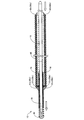
- FIG. 1 is an explanatory diagram illustrating the overall configuration of the guide wire 1 of the first embodiment.
- the guide wire 1 is a medical device used when inserting a catheter into a blood vessel or a digestive organ, and includes a core shaft 10, a coil body 20, a tip coil body 30, a tip joining portion 40, and an engaging portion 50.
- the engaged portion 60 and the inner joint portion 70 are provided.
- the left side of FIG. 1 is referred to as the “tip side” of the guide wire 1 and each component
- the right side of FIG. 1 is referred to as the “base end side” of the guide wire 1 and each component.
- the tip end side of the guide wire 1 is the side to be inserted into the body (distal side), and the proximal end side of the guide wire 1 is the side operated by a technician such as a doctor (proximal side).
- the core shaft 10 is a long (tapered) member configured so that the outer diameter decreases from the base end side to the tip end side.
- the core shaft 10 can be made of, for example, a stainless alloy (SUS302, SUS304, SUS316, etc.), a superelastic alloy such as Ni—Ti alloy, a piano wire, a nickel-chromium alloy, a cobalt alloy, a tungsten, or the like. ..
- the core shaft 10 may be formed of a known material other than the above.
- the length of the core shaft 10 is not particularly limited, but for example, a range of 1000 mm to 3000 mm can be exemplified.
- the outer diameter of the core shaft 10 is also not particularly limited, and for example, a range of 0.1 mm to 1.0 mm can be exemplified.
- a tip joint 40 is formed at the tip of the core shaft 10.
- the tip joint 40 is formed of a metal solder such as silver brazing, gold brazing, zinc, Sn—Ag alloy, Au—Sn alloy, etc., and the tip of the tip coil body 30 and the tip of the core shaft 10 are fixed by this metal solder. Has been done.
- the tip joining portion 40 may be formed of an adhesive such as an epoxy adhesive, and the tip of the tip coil body 30 and the tip of the core shaft 10 may be fixed by the adhesive.
- the coil body 20 is composed of one or a plurality of coils, and is wound around the core shaft 10 so as to cover a part of the core shaft 10 and the tip coil body 30.
- the coil body 20 is not fixed to the core shaft 10 and is configured to be movable (sliding) relative to the core shaft 10. That is, the coil body 20 is configured to be reciprocally movable along the axial direction of the core shaft 10. Further, the coil body 20 is configured to be rotatable relative to the core shaft 10 (coaxial rotation). That is, the coil body 20 is configured to be rotatable around the axis of the core shaft 10 as a rotation axis.
- the coil constituting the coil body 20 may be a single coil formed by spirally winding one wire having a circular cross section to form a cylindrical shape, or a stranded wire obtained by twisting a plurality of wires into a cylindrical shape. It may be a hollow stranded coil formed in. Further, the coil body 20 may be configured by combining a single coil and a hollow stranded coil.
- the coil body 20 includes, for example, stainless alloys (SUS302, SUS304, SUS316, etc.), superelastic alloys such as Ni—Ti alloys, piano wires, nickel-chromium alloys, radiation permeable alloys such as cobalt alloys, gold, platinum, etc.
- the coil body 20 can be formed of a radiation-impermeable alloy such as tungsten or an alloy containing these elements (for example, a platinum-nickel alloy).
- the coil body 20 may be formed of a known material other than the above.
- the length L1 of the coil body 20 is shorter than the length of the core shaft 10.
- the coil body 20 has a constant outer diameter.
- the outer diameter of the coil body 20 is not particularly limited, but for example, a range of 1.0 mm to 2.0 mm can be exemplified.
- the tip coil body 30 is composed of a single coil or a hollow stranded coil, and is wound around the core shaft 10 so as to cover the outer circumference on the tip side of the core shaft 10.
- the tip coil body 30 is wound around a part of a small diameter portion and a tapered portion on the tip side of the core shaft 10.
- the length of the tip coil body 30 is shorter than that of the core shaft 10 and the coil body 20.
- the length of the tip coil body 30 is not particularly limited, but for example, 10 mm to 100 mm can be exemplified.
- the inner diameter of the tip coil body 30 is larger than the outer diameter of the core shaft 10, and the outer diameter of the tip coil body 30 is smaller than the inner diameter of the coil body 20.
- the outer diameter of the tip coil body 30 is made constant from the tip to the base end.
- the outer diameter of the tip coil body 30 is not particularly limited, but for example, a range of 0.1 mm to 1.0 mm can be exemplified.
- the tip of the tip coil body 30 is joined to the tip of the core shaft 10 by the tip joining portion 40.
- the base end of the tip coil body 30 is joined to the tapered portion of the core shaft 10 by the inner joint portion 70.
- the tip coil body 30 is fixed to the core shaft 10 by the tip joint 40 and the inner joint 70.
- the inner joint portion 70 may be formed of the same material as the tip joint portion 40, or may be formed of a different material.
- the winding direction of the tip coil body 30 may be the same as or different from the winding direction of the coil body 20.
- the coil pitch of the tip coil body 30 may be the same as or different from the coil pitch of the coil body 20.
- the tip coil body 30 has a loosely wound portion and a tightly wound portion having different coil pitches, and a loosely wound portion is formed on the tip side and a tightly wound portion is formed on the base end side.
- the engaging portion 50 is provided on the outer periphery of the core shaft 10 and is a stopper that engages with the engaged portion 60 of the coil body 20, and includes the tip end side engaging portion 51 and the proximal end side engaging portion 52. ..
- the distal end side engaging portion 51 and the proximal end side engaging portion 52 are ring-shaped (ring-shaped) members fixed to the outer periphery of the core shaft 10, respectively, in other words, along the outer peripheral direction of the core shaft 10. It is an annular protrusion formed.
- the tip end side engaging portion 51 and the proximal end side engaging portion 52 may be formed of the same material as the tip end joining portion 40, or may be formed of a material different from that of the tip end joining portion 40.
- the outer diameters of the tip end side engaging portion 51 and the proximal end side engaging portion 52 are larger than the outer diameter of the tip coil body 30 and the core shaft 10 and smaller than the inner diameter of the coil body 20.
- the distal end side engaging portion 51 and the proximal end side engaging portion 52 are arranged at positions inside the coil body 20 in the core shaft 10.
- the tip end side engaging portion 51 is formed on the tip end side of the core shaft 10 with respect to the proximal end side engaging portion 52, and here, it is formed at a position of the core shaft 10 covered by the tip coil body 30.
- the proximal end side engaging portion 52 is provided between the distal end and the proximal end of the distal coil body 30.
- the tip end side engaging portion 51 and the proximal end side engaging portion 52 engage with the distal end side engaged portion 61 and the proximal end side engaged portion 62, which will be described later, to move the coil body 20 in the axial direction. regulate.
- the distance D1 is shorter than the length L1 of the coil body 20.
- the engaged portion 60 is provided on the coil body 20 and is a stopper that engages with the engaging portion 50 of the core shaft 10, and includes the distal end side engaged portion 61 and the proximal end side engaged portion 62. ..
- the distal end side engaged portion 61 and the proximal end side engaged portion 62 are ring-shaped (ring-shaped) members joined to both ends of the coil body 20, and are formed of the same material as the tip joining portion 40. ..
- the inner diameters of the distal end side engaged portion 61 and the proximal end side engaged portion 62 are configured to be smaller than the inner diameter of the coil body 20. Therefore, the inner peripheral surfaces of the distal end side engaged portion 61 and the proximal end side engaged portion 62 project inward from the inner peripheral surface of the coil body 20.
- the tip side engaged portion 61 is joined to the tip of the coil body 20 and is located on the tip side of the tip side engaging portion 51 provided on the core shaft 10.
- the inner diameter of the tip-side engaged portion 61 is smaller than the outer diameter of the tip-side engaged portion 51 provided on the core shaft 10. Therefore, when the coil body 20 moves in the proximal direction (right direction in FIG. 1) relative to the core shaft 10, the tip-side engaged portion 61 engages (contacts) with the tip-side engaging portion 51. ).
- a taper is formed on the outside of the tip-side engaged portion 61, and the tip-side engaged portion 61 is configured such that the outer diameter increases from the tip side toward the proximal end side. As a result, in the guide wire 1, the step between the outer diameter of the tip coil body 30 and the outer diameter of the coil body 20 can be made gentle.
- the base end side engaged portion 62 is joined to the base end of the coil body 20 and is located closer to the base end side than the base end side engaging portion 52 provided on the core shaft 10.
- the inner diameter of the base end side engaged portion 62 is smaller than the outer diameter of the base end side engaging portion 52 provided on the core shaft 10. Therefore, when the coil body 20 moves in the tip direction (left direction in FIG. 1) relative to the core shaft 10, the base end side engaged portion 62 engages with the base end side engaging portion 52 ( Contact.
- a taper is formed on the outside of the base end side engaged portion 62, and the proximal end side engaged portion 62 is configured such that the outer diameter increases from the proximal end side toward the distal end side. ..
- the step between the outer diameter of the coil body 20 and the outer diameter of the core shaft 10 can be made smooth.
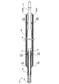
- FIG. 2 is an explanatory diagram illustrating a state in which the coil body 20 is relatively moved in the proximal direction (base end side) of the core shaft 10.
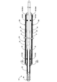
- FIG. 3 is an explanatory view illustrating a state in which the coil body 20 is relatively moved toward the tip end direction (tip side) of the core shaft 10.
- the length L1 of the coil body 20 is longer than the distance D1 from the tip end side engaging portion 51 to the proximal end side engaging portion 52, and the coil body 20 has the distal end side engaging portion 51 and the proximal end.
- the core shaft 10 is configured to be able to reciprocate in a range from the position shown in FIG. 2 to the position shown in FIG. 3 along the axial direction of the core shaft 10. That is, the guide wire 1 changes the length (protrusion amount) of the small diameter portion including the tip coil body 30 and the tip joint 40 protruding from the tip of the coil body 20 without changing the position of the coil body 20. It is possible, and the small diameter portion can be rotated relative to the coil body 20.
- the distal end side engaged portion 61 comes into contact with the distal end side engaging portion 51 and is directed toward the proximal end of the coil body 20. Regulate further movement to. At this time, the length (protrusion amount) of the small diameter portion including the tip coil body 30 and the tip joint 40 protruding from the tip of the coil body 20 is maximized.
- the amount of protrusion at this time is arbitrary, but for example, a range of 50 to 200 mm can be exemplified.
- the proximal end side engaged portion 62 comes into contact with the proximal end side engaging portion 52, and the coil body 20 Regulate further movement towards the tip.
- the length (protrusion amount) of the small-diameter portion including the tip coil body 30 and the tip joint 40 protruding from the tip of the coil body 20 is minimized.
- the amount of protrusion at this time is arbitrary, but for example, a range of 10 to 100 mm can be exemplified.
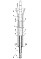
- FIG. 4 is an explanatory diagram illustrating a procedure using the guide wire 1A of the comparative example.
- FIG. 5 is an explanatory diagram illustrating a procedure using the guide wire 1 of the present embodiment.
- the guide wire 1A of the comparative example shown in FIG. 4 is different from the guide wire 1 of the present embodiment in that the coil body 20 is not provided. That is, the guide wire 1A of the comparative example has a configuration in which the tip coil body 30 is arranged at the tip of the core shaft 10 and the core shaft 10 is exposed on the proximal end side of the core shaft 10.
- a guide wire 1A of a comparative example having an outer diameter of about 0.014 inch (0.36 mm) is used to aim at a guiding catheter 91 having a large diameter of 6 Fr to 7 Fr.
- the guiding catheter 91 cannot be delivered to the target blood vessel with the guide wire 1A alone because the support of the guide wire 1A is insufficient. Therefore, as shown in FIG. 4, it is necessary to use the support catheter 92 and the microcatheter 93 together to deliver the guiding catheter to the target blood vessel.
- the core shaft 10 and the tip coil body 30 at the tip of the guide wire 1A of the comparative example have a large diameter, the rigidity of the tip becomes high, so that the support catheter 92 and the microcatheter 93 become unnecessary, while the guide is performed in the blood vessel.
- a blood clot may cause a blood vessel to be perforated when the guide wire is advanced to a blood vessel that does not appear on the screen under fluoroscopy.
- the guide wire 1 of the present embodiment has two types of outer diameters, a tip coil body 30 and a coil body 20, and has a configuration in which a large diameter guide wire and a small diameter guide wire are integrated. There is. Since the tip of the guide wire 1 is composed of the tip coil body 30 having a small diameter, it is possible to reduce the possibility of perforating the blood vessel when the guide wire 1 is advanced and the target blood vessel is selected. Further, since the guide wire 1 is provided with the coil body 20 having a large diameter on the proximal end side of the tip coil body 30, the guiding catheter can be used only with the guide wire 1 without using the support catheter 92 or the microcatheter 93. It has the rigidity to deliver 91 to the target blood vessel. Therefore, according to the guide wire 1 of the present embodiment, the guiding catheter 91 can be delivered to the target blood vessel without using the support catheter or the microcatheter, so that the cost required for the support catheter or the microcatheter can be reduced.
- the rigidity of the tip end side of the guide wire 1 is increased by moving the coil body 20 relative to the core shaft 10. It can be changed. That is, according to the guide wire 1 of the present embodiment, the rigidity of the tip portion of the guide wire can be adjusted by a technician. Specifically, as shown in FIG. 2, the tip side of the guide wire 1 is increased by increasing the length of the small diameter portion formed by the tip coil body 30 protruding from the tip of the coil body 20 and the core shaft 10. The rigidity of the coil can be reduced. Thereby, for example, when advancing the guide wire in the blood vessel, the occurrence of blood vessel perforation can be suppressed. On the other hand, as shown in FIG.
- the length of the small diameter portion formed by the tip coil body 30 protruding from the tip of the coil body 20 and the core shaft 10 is shortened, and the large diameter coil body 20 is held on the tip side.
- the rigidity of the tip side of the guide wire 1 can be increased. This makes it possible to improve the backup property, for example, when passing through a lesion or when delivering a large-diameter guiding catheter 91 to a target blood vessel.
- the tip side is engaged.
- the joint portion 61 comes into contact with the tip end side engaging portion 51 to restrict further movement of the coil body 20 toward the proximal end.
- the proximal end side engaged portion 62 becomes the proximal end side engaging portion 52. To regulate further movement of the coil body 20 toward the tip end. As a result, the relative position between the guide wire 1 and the core shaft can be maintained within an appropriate range, and the procedure using the guide wire 1 can be facilitated.
- the tip end side engaging portion 51 and the proximal end side engaging portion 52 are arranged in a region of the core shaft 10 located inside the coil body 20.
- the tip end side engaging portion 51 and the proximal end side engaging portion 52 are not exposed on the outer surface of the guide wire 1.
- the outer surface of the guide wire 1 can be made smooth.
- the guide wire can be easily advanced in the blood vessel (improvement of interoperability and operability with the combined device).
- the tip end side engaging portion 51 and the proximal end side engaging portion 52 are each configured as an annular protrusion.
- the tip end side engaged portion 61 and the proximal end side engaged portion 62 can be easily engaged.
- the tip end side engaged portion 61 and the proximal end side engaged portion 62 are provided at both ends of the coil body 20, the tip end side engaged portion 61 is provided. The 61 and the base end side engaged portion 62 can be easily joined to the coil body 20.
- the tip end side engaged portion 61 and the proximal end side engaged portion 62 are provided at both ends of the coil body 20, one of the distal end side engaged portion 61 and the proximal end side engaged portion 62
- the range of movement of the coil body 20 from when one is engaged to when the other is engaged can be set relatively wide. As a result, the degree of freedom in setting the movement range of the coil body 20 can be increased.
- the tip end side engaged portion 61 and the proximal end side engaged portion 62 each have an annular outer shape and a taper is formed. Due to this taper, the step between the core shaft and the tubular body can be smoothed, and the guide wire can be easily advanced in the blood vessel.
- the core shaft 10 has a reduced diameter at the tip of the guide wire 1 and the tip coil body 30 is arranged on the outside, the rigidity of the tip side of the tubular body is increased. Can be lowered. As a result, the occurrence of blood vessel perforation due to the tip of the guide wire can be further suppressed.
- FIG. 6 is an explanatory diagram illustrating the overall configuration of the guide wire 1B of the second embodiment.
- the guide wire 1B of the second embodiment is different from the guide wire 1 of the first embodiment in the positions of the tip end side engaging portion 51 and the proximal end side engaged portion 62 on the core shaft 10. Since other configurations are the same as those of the guide wire 1 of the first embodiment, the description thereof will be omitted.
- the tip end side engaging portion 51b is located on the tip end side of the core shaft 10 with respect to the tip end side engaged portion 61 of the coil body 20, and the base end side engaging portion 52.
- the shapes of the distal end side engaging portion 51b and the proximal end side engaging portion 52b may be the same as or different from the distal end side engaging portion 51 and the proximal end side engaging portion 52 of the first embodiment. Good.
- the distance D2 from the tip end side engaging portion 51b to the proximal end side engaging portion 52b is longer than the length L1 of the coil body 20.
- the coil body 20 is configured to be reciprocally movable along the axial direction of the core shaft 10 between the distal end side engaging portion 51b and the proximal end side engaging portion 52b.
- the base end side engaged portion 62b of the core shaft 10 comes into contact with the base end side engaging portion 52b and moves toward the base end of the coil body 20. Regulate further movement of.
- the tip end side engaged portion 61b of the coil body 20 comes into contact with the tip end side engaging portion 51b, and further toward the tip end side of the coil body 20. Regulate movement.
- the shapes of the distal end side engaged portion 61b and the proximal end side engaged portion 62b may be the same as those of the distal end side engaged portion 61 and the proximal end side engaged portion 62 of the first embodiment. It may be different.
- the tip end side engaging portion 51b and the proximal end side engaging portion 52b are the distal end side engaged portion 61b and the proximal end side engaged portion of the coil body 20. It may be arranged outside 62b. That is, the distal end side engaging portion 51b and the proximal end side engaging portion 52b may not be arranged inside the coil body 20. Even in this case, the rigidity of the tip end side of the guide wire 1B can be changed by moving the coil body 20 relative to the core shaft 10.
- FIG. 7 is an explanatory view illustrating the overall configuration of the guide wire 1C of the third embodiment.
- the guide wire 1C of the third embodiment is different from the guide wire 1 of the first embodiment in that the core shaft 10 does not have the base end side engaging portion 52. Since other configurations are the same as those of the guide wire 1 of the first embodiment, the description thereof will be omitted.
- the tip-side engaged portion 61c becomes the tip-side engaging portion 51c as in the first embodiment. Contact to regulate further movement of the coil body 20 towards the proximal end.
- the coil body 20 when the coil body 20 is relatively moved toward the tip of the core shaft 10, the coil body 20 is moved toward the tip of the coil body 20 until the base end side engaged portion 62c contacts the tip end side engaging portion 51c. Is not regulated.
- the shapes of the tip side engaged portion 61c, the proximal end side engaged portion 62c, and the distal end side engaged portion 51c are the distal end side engaged portion 61 and the proximal end side engaged portion 62 of the first embodiment. , And may be the same as or different from the tip side engaging portion 51.
- the guide wire 1C does not have to include the proximal end side engaging portion 52. Even in this case, when the coil body 20 moves toward the proximal end of the core shaft 10, the distal end side engaged portion 61c comes into contact with the distal end side engaging portion 51c and the proximal end direction of the coil body 20. Since further movement to is restricted, the relative position between the guide wire 1 and the core shaft can be kept within an appropriate range. As a result, it is possible to facilitate the procedure using the guide wire 1.
- FIG. 8 is an explanatory view illustrating the overall configuration of the guide wire 1D of the fourth embodiment.
- the guide wire 1D of the fourth embodiment is different from the guide wire 1 of the first embodiment in that the core shaft 10 does not have the tip end side engaging portion 51. Since other configurations are the same as those of the guide wire 1 of the first embodiment, the description thereof will be omitted.
- the proximal end side engaged portion 62d becomes the proximal end side engaging portion 52d as in the first embodiment. To regulate further movement of the coil body 20 toward the tip end.
- the coil body 20 when the coil body 20 is relatively moved toward the proximal end of the core shaft 10, the coil body 20 is moved toward the proximal end of the coil body 20 until the distal end side engaged portion 61d comes into contact with the proximal end side engaging portion 52d. Movement is not regulated.
- the shapes of the tip end side engaged portion 61d, the proximal end side engaged portion 62d, and the proximal end side engaged portion 52d are the distal end side engaged portion 61 and the proximal end side engaged portion of the first embodiment. It may be the same as or different from 62 and the proximal end side engaging portion 52.
- the guide wire 1D does not have to include the tip end side engaging portion 51. Even in this case, when the coil body 20 moves toward the tip end of the core shaft 10, the proximal end side engaged portion 62 comes into contact with the proximal end side engaging portion 52 and the tip end direction of the coil body 20. Since further movement to is restricted, the relative position between the guide wire 1 and the core shaft can be kept within an appropriate range. As a result, it is possible to facilitate the procedure using the guide wire 1.
- FIG. 9 is an explanatory diagram illustrating the overall configuration of the guide wire 1E according to the fifth embodiment.
- the guide wire 1E of the fifth embodiment is different from the guide wire 1 of the first embodiment in that it includes a tubular body 25 instead of the coil body 20. Since other configurations are the same as those of the guide wire 1 of the first embodiment, the description thereof will be omitted.
- the tubular body 25 is a tube formed of resin, and a core shaft 10 is arranged inside.
- the resin material forming the tubular body 25 is not particularly limited, and for example, PTFE (polytetrafluoroethylene), PVDF (polyvinylidene fluoride), PFA (perfluoroalkoxy alkane), FEP (perfluoroethylene propene), and the like.
- ETFE ethylene tetrafluoroethylene
- PE polyethylene
- PP polypropylene
- the tubular body 25 is not fixed to the core shaft 10 and is configured to be reciprocally movable along the axial direction of the core shaft 10. Further, the tubular body 25 is configured to be rotatable relative to the core shaft 10 (coaxial rotation).
- the distal end side engaged portion 61e and the proximal end side engaged portion 62e are attached to both ends of the tubular body 25.
- the shapes of the distal end side engaged portion 61e and the proximal end side engaged portion 62e may be the same as those of the distal end side engaged portion 61 and the proximal end side engaged portion 62 of the first embodiment. It may be different.
- the guide wire does not have to include the coil body 20 as in the guide wire 1E of the present embodiment described above. That is, the tubular body forming the large diameter portion of the guide wire is not limited to the coil body 20. Even if the tube is made of resin like the tubular body 25 of the present embodiment, the rigidity of the tip side of the guide wire 1E can be changed by moving the tubular body 25 relative to the core shaft 10. Can be done.
- FIG. 10 is an explanatory view illustrating the overall configuration of the guide wire 1F of the sixth embodiment.
- the guide wire 1F of the sixth embodiment is different from the guide wire 1 of the first embodiment in the shapes of the distal end side engaged portion 61 and the proximal end side engaged portion 62. Since other configurations are the same as those of the guide wire 1 of the first embodiment, the description thereof will be omitted.
- Neither the tip end side engaged portion 61f nor the proximal end side engaged portion 62f of the sixth embodiment has a taper. The other parts are the same as those of the tip end side engaged portion 61 and the proximal end side engaged portion 62 of the first embodiment.
- the base end side engaged portion 62f of the core shaft 10 comes into contact with the base end side engaging portion 52f, and the coil. Restrict further movement of body 20 towards the proximal end.
- the tip end side engaged portion 61f of the coil body 20 comes into contact with the tip end side engaging portion 51f, and further toward the tip end side of the coil body 20. Regulate movement.
- the shape of the tip-side engaged portion 61f and the tip-side engaging portion 51f can be any shape as long as they can be engaged with each other.
- the shapes of the base end side engaged portion 62f and the base end side engaging portion 52f can be any shape as long as they can be engaged with each other.
- the rigidity of the tip end side of the guide wire 1F can be changed by moving the coil body 20 relative to the core shaft 10. It should be noted that if the tip end side engaged portion 61 and the proximal end side engaged portion 62 are provided with a taper, the step between the core shaft 10 and the coil body 20 can be made smooth, and the guide wire can be provided in the blood vessel. It is more preferable because it can be easily advanced.
- FIG. 11 is an explanatory diagram illustrating the overall configuration of the guide wire 1G according to the seventh embodiment.
- the guide wire 1G of the seventh embodiment has the respective positions and shapes of the tip side engaged portion 61 and the proximal end side engaged portion 62, and the tip side engaging portion.
- the positions of the joint portion 51 and the proximal end side engaging portion 52 are different. Since other configurations are the same as those of the guide wire 1 of the first embodiment, the description thereof will be omitted.
- the tip end side engaged portion 61 g and the proximal end side engaged portion 62 g of the seventh embodiment are fixed to the inside of the coil body 20 instead of both ends of the coil body 20, respectively.
- the distance D3 from the tip end side engaged portion 61 g to the proximal end side engaged portion 62 g of the seventh embodiment is smaller than the length L1 of the coil body 20.
- the distal end side engaged portion 61g and the proximal end side engaged portion 62g are ring-shaped (ring-shaped) members joined to the inside of the coil body 20, and the distal end side engaged portion 61g is the proximal end side covering. It is arranged on the tip side relative to the engaging portion 62 g.
- the tip end side engaged portion 61 g and the proximal end side engaged portion 62 g are coils. It protrudes inside the body 20.
- a tip forming portion 81 and a base end forming portion 82 are joined to both ends of the coil body 20.
- the tip forming portion 81 and the base end forming portion 82 do not need to have an engaged portion and may have any shape.
- the tip end side engaging portion 51g and the proximal end side engaging portion 52g of the seventh embodiment are formed between the distal end side engaged portion 61g and the proximal end side engaged portion 62g, respectively.
- the distance D4 from the distal end side engaging portion 51g to the proximal end side engaging portion 52g is smaller than the distance D1 from the distal end side engaging portion 51 to the proximal end side engaging portion 52 of the first embodiment.
- the shapes of the tip end side engaging portion 51g and the proximal end side engaging portion 52g may be the same as or different from the tip end side engaging portion 51 and the proximal end side engaging portion 52 of the first embodiment. Good.
- the shapes of the tip-side engaged portion 61 g and the tip-side engaged portion 51 g can be any shape as long as they can be engaged with each other.
- the shapes of the base end side engaged portion 62 g and the base end side engaged portion 52 g can be any shape as long as they can be engaged with each other.
- the tip end side engaged portion 61 g and the proximal end side engaged portion 62 g of the seventh embodiment project inside the coil body 20, when the coil body 20 is relatively moved toward the proximal end of the core shaft 10.
- the tip-side engaged portion 61 g engages with the tip-side engaged portion 51 g.
- the proximal end side engaged portion 62 g engages with the proximal end side engaging portion 52 g.
- the positions of the tip end side engaged portion 61 and the proximal end side engaged portion 62 are not limited to both ends of the coil body 20.
- the tip end side engaged portion 61 g and the proximal end side engaged portion 62 g can be fixed at arbitrary positions inside the coil body 20. Even in this case, the relative positions of the guide wire 1G and the core shaft 10 can be maintained within an appropriate range, and the procedure using the guide wire 1G can be facilitated.
- FIG. 12 is an explanatory diagram illustrating the overall configuration of the guide wire 1H according to the eighth embodiment.
- the guide wire 1H of the eighth embodiment is different in the position and shape of the engaging portion 50 and the engaged portion 60 as compared with the guide wire 1 of the first embodiment. Since other configurations are the same as those of the guide wire 1 of the first embodiment, the description thereof will be omitted.
- the engaging portion 50h of the eighth embodiment unlike the first embodiment, one protrusion comes into contact with both the distal end side engaged portion 61h and the proximal end side engaged portion 62h.
- the engaging portion 50h a part of the core shaft 10 is expanded in a predetermined section, the tip end side of the expanded diameter section is in contact with the tip side engaged portion 61h, and the proximal end side of the enlarged diameter section is the base. It comes into contact with the end-side engaged portion 62h.
- the distal end side engaged portion 61h and the proximal end side engaged portion 62h are fixed to the inside of the coil body 20 instead of both ends of the coil body 20, respectively.
- the distal end side engaged portion 61h and the proximal end side engaged portion 62h are ring-shaped (ring-shaped) members joined to the inside of the coil body 20, and each protrudes inside the coil body 20.
- a tip forming portion 81 and a base end forming portion 82 are joined to both ends of the coil body 20.
- the tip forming portion 81 and the base end forming portion 82 do not need to have an engaged portion and may have any shape.
- the engaging portion 50h has a protrusion that contacts the tip end side engaged portion 61h and a protrusion that contacts the proximal end side engaged portion 62. It is not necessary to provide them separately, and they may be configured as one protrusion that comes into contact with both. Further, the engaging portion 50 does not have to be formed separately from the core shaft 10, and may be formed as a part of the core shaft 10.
- FIG. 13 is an explanatory diagram illustrating the overall configuration of the guide wire 1J of the ninth embodiment.
- the guide wire 1J of the ninth embodiment is different from the guide wire 1 of the first embodiment in that it does not include the tip coil body 30. Since other configurations are the same as those of the guide wire 1 of the first embodiment, the description thereof will be omitted.
- the guide wire 1J of the ninth embodiment can change the length of the core shaft 10 protruding from the tip of the coil body 20 by moving the coil body 20 relative to the core shaft 10.
- the rigidity of the tip end side of the guide wire 1 can be changed by moving the coil body 20 relative to the core shaft 10. Specifically, by increasing the length of the core shaft 10 as a small diameter portion protruding from the tip of the coil body 20, the rigidity of the tip side of the guide wire 1 can be reduced. On the other hand, by shortening the length of the core shaft 10 protruding from the tip of the coil body 20 and bringing the coil body 20 having a large diameter to the tip side, the rigidity of the tip side of the guide wire 1 can be increased.
- FIG. 14 is an explanatory diagram illustrating the overall configuration of the guide wire 1K according to the tenth embodiment.
- the guide wire 1K of the tenth embodiment has a different moving range of the coil body 20 with respect to the core shaft 10 as compared with the guide wire 1 of the first embodiment. Since other configurations are the same as those of the guide wire 1 of the first embodiment, the description thereof will be omitted.
- the proximal end side engaging portion 52k is arranged on the distal end side of the proximal end side engaging portion 52 of the first embodiment.
- the tip of the coil body 20 is closer to the tip joining portion 40. Located on the tip side. That is, when the base end side engaged portion 62 comes into contact with the base end side engaging portion 52k, the small diameter portion composed of the tip coil body 30 and the core shaft 10 does not protrude from the tip end side of the coil body 20.
- the small diameter portion protruding from the tip of the coil body 20 is lengthened, thereby reducing the rigidity of the tip side of the guide wire 1. Can be made to.
- the large-diameter coil body 20 is brought to the tip side, whereby the guide wire 1 The rigidity of the tip side of the coil can be increased.
- FIG. 15 is an explanatory view illustrating the overall configuration of the guide wire 1L of the eleventh embodiment.
- the guide wire 1L of the eleventh embodiment is different from the guide wire 1 of the first embodiment in that the tip-side engaging portion 51 has the function of the inner joint portion 70. Since other configurations are the same as those of the guide wire 1 of the first embodiment, the description thereof will be omitted.
- the tip end side engaging portion 51L of the eleventh embodiment is an annular protrusion formed at the base end portion of the tip coil body 30, and the base end portion of the tip coil body 30 is fixed to the core shaft 10.
- the outer diameter of the tip side engaging portion 51L is larger than the outer diameter of the tip coil body 30 and the core shaft 10, and by engaging with the tip side engaged portion 61, the base end of the core shaft 10 of the coil body 20 Regulate movement in the direction. Even in this case, the relative position between the coil body 20 and the core shaft can be maintained within an appropriate range, and the procedure using the guide wire can be facilitated. Further, by moving the coil body 20 relative to the core shaft 10, the rigidity of the tip end side of the guide wire 1 can be changed.
- FIG. 16 is an explanatory diagram illustrating the overall configuration of the guide wire 1M according to the twelfth embodiment.
- the configurations of the guide wires illustrated in the first to eleventh embodiments may be combined as appropriate.
- a configuration having the engaging portion 50h of the eighth embodiment as in the guide wire 1M of the twelfth embodiment shown in FIG. 16 and a configuration not including the tip coil body 30 as in the ninth embodiment. May be combined. Even in this case, the rigidity of the tip end side of the guide wire 1 can be changed by moving the coil body 20 relative to the core shaft 10.
- the tip end side engaged portion 61 is provided at the tip of the coil body 20, and as in the eleventh embodiment, the proximal end side engaged portion 62 g is provided. It may be provided inside the coil body 20.
- FIG. 17 is an explanatory diagram illustrating the overall configuration of the guide wire 1N according to the thirteenth embodiment.
- the guide wire 1N of the thirteenth embodiment is different from the guide wire 1 of the first embodiment (FIG. 1) in that it includes a tubular body 25n instead of the coil body 20. Since other configurations are the same as those of the guide wire 1 of the first embodiment, the description thereof will be omitted.
- the tubular body 25n of the thirteenth embodiment includes an inner layer 21, a reinforcing layer 22, and an outer layer 26.
- the tubular body 25n is not fixed to the core shaft 10 and is configured to be movable (sliding) relative to the core shaft 10. That is, the tubular body 25n is configured to be reciprocally movable along the axial direction of the core shaft 10. Further, the tubular body 25n is configured to be rotatable relative to the core shaft 10 (coaxial rotation). That is, the tubular body 25n is configured to be rotatable around the axis of the core shaft 10 as a rotation axis.
- the inner layer 21 is a tube made of resin, and the core shaft 10 is arranged inside.
- the resin material forming the inner layer 21 is not particularly limited, and for example, PTFE (polytetrafluoroethylene), PVDF (polyvinylidene fluoride), PFA (perfluoroalkoxy alkane), FEP (perfluoroethylene propene), ETFE ( Ethylene tetrafluoroethylene), PE (polyethylene), PP (polypropylene) can be exemplified.
- the inner layer 21 is formed of PTFE.
- a thrombus or the like may flow into the inside of the tubular body 25n from the tip side of the tubular body 25n.
- the inner layer 21 is formed of PTFE, the adhesion of thrombi to the inner layer 21 can be particularly suppressed, and the relative movement of the tubular body 25n and the deterioration of the smoothness of relative rotation due to the adhesion can be suppressed. it can.
- the reinforcing layer 22 is a braided body (metal blade layer) in which the first and second strands are woven into each other in a mesh shape, is arranged on the outer periphery of the inner layer 21, and covers the outer layer 26 (). It is buried).
- the tubular body 25n with the reinforcing layer 22 having high rigidity, the wall thickness of the tubular body 25n can be reduced while ensuring the bending rigidity of the tubular body 25n, and the outer diameter of the tubular body 25n can be reduced. It can be made smaller.
- the first and second strands may be round or flat. Further, one of the first and second strands may be a round wire and the other may be a flat wire.
- the reinforcing layer 22 of the present embodiment covers the entire inner layer 21, it may be configured to cover a part of the inner layer 21. Further, the reinforcing layer 22 of the present embodiment has a constant bending rigidity from the tip end side to the base end side, but the reinforcing layer 22 has, for example, the pitch and outer diameter of the first and second strands. The bending rigidity on the distal end side and the proximal end side may be changed by changing the bending rigidity. Further, the blade structure of the reinforcing layer 22 may be coiling as well as braiding. Further, for example, the combination may be performed so that the tip end side is coiling and the base end side is braiding.
- the outer layer 26 is formed of resin and covers the inner layer 21 and the reinforcing layer 22.
- the resin material forming the outer layer 26 is not particularly limited, and examples thereof include polyamide, polyamide elastomer, polyester, polyurethane, and polyurethane elastomer.
- the flexural rigidity of the outer layer 26 of the present embodiment is constant from the tip end side to the base end side. However, for example, by changing the hardness of the resin forming the outer layer 26, the tip end side and the base end side can be changed. The flexural rigidity may be changed.
- the engaged portion 60n has the same configuration as the engaged portion 60 of the first embodiment, and includes the tip end side engaged portion 61n and the proximal end side engaged portion 62n.
- the distal end side engaged portion 61n and the proximal end side engaged portion 62n are ring-shaped (ring-shaped) members joined to both ends of the tubular body 25n, and the end portions of the reinforcing layer 22 are inserted therein. There is.
- the inner diameters of the distal end side engaged portion 61n and the proximal end side engaged portion 62n are configured to be smaller than the inner diameter of the tubular body 25n.
- the inner peripheral surfaces of the distal end side engaged portion 61n and the proximal end side engaged portion 62n project inward from the inner peripheral surface of the tubular body 25n.
- the tip side engaged portion 61n engages (contacts) with the tip side engaging portion 51 when the tubular body 25n moves in the proximal direction (right direction in FIG. 17) relative to the core shaft 10.
- the base end side engaged portion 62n engages (contacts) with the base end side engaging portion 52 when the tubular body 25n moves in the tip direction (left direction in FIG. 17) relative to the core shaft 10. ).
- a taper is formed on the outside of each of the distal end side engaged portion 61n and the proximal end side engaged portion 62n.
- the guide wire includes a tubular body 25n composed of an inner layer 21, a reinforcing layer 22, and an outer layer 26 instead of the coil body 20 (FIG. 1). May be good. Even in this case, the rigidity of the tip end side of the guide wire 1N can be changed by moving the tubular body 25n relative to the core shaft 10. Further, according to the guide wire 1N of the present embodiment, since the inner layer 21 is arranged inside the tubular body 25n, when the guide wire 1N is used in the human lumen, it is moved to the inside of the tubular body 25n. Adhesion of blood clots can be suppressed.
- the guide wire 1N of the present embodiment since the outer layer 26 is arranged on the outside of the tubular body 25n, when the guide wire 1N is used in the human lumen, the outer circumference of the tubular body 25n and the human body The frictional force generated by the contact with the inner wall of the lumen can be reduced. Further, according to the guide wire 1N of the present embodiment, since the tubular body 25n is provided with the reinforcing layer 22 having high rigidity, the wall thickness of the tubular body 25n can be increased while ensuring the bending rigidity of the tubular body 25n. Can be made thinner. As a result, the outer diameter of the tubular body 25n can be reduced.
- FIG. 18 is an explanatory view illustrating the overall configuration of the guide wire 1P of the 14th embodiment.
- the guide wire 1P of the 14th embodiment is different from the guide wire 1N of the 13th embodiment (FIG. 13) in that the rigidity is changed between the tip end side and the base end side of the outer layer 26. Since other configurations are the same as those of the guide wire 1N of the thirteenth embodiment, the description thereof will be omitted.
- the tubular body 25p of the 14th embodiment includes an inner layer 21, a reinforcing layer 22, and an outer layer 26p. Since the inner layer 21 and the reinforcing layer 22 are the same as those in the thirteenth embodiment, the description thereof will be omitted.
- the outer layer 26p is formed of resin and covers the inner layer 21 and the reinforcing layer 22.
- the resin material forming the outer layer 26p is not particularly limited, but the same resin as the resin exemplified in the thirteenth embodiment can be adopted.
- the outer layer 26p has a structure in which a plurality of sections having different resin hardnesses are continuous.
- first outer layer 26p1 the outer layer of the first section on the most tip side
- second outer layer 26p2 the outer layer of the second section adjacent to the base end side of the first outer layer 26p1
- the outer layer of the third section on the most proximal side is called "third outer layer 26p3".
- the outer layer 26p has a configuration in which the first outer layer 26p1, the second outer layer 26p2, and the third outer layer 26p3 are arranged side by side from the tip end side to the base end side.
- the outer layer 26p includes three types of outer layers having different resin hardnesses from each other, but the number of sections of the outer layer 26p having different resin hardness is not limited to three, and two. It may be four or more.
- the outer layer 26p is configured such that the hardness of the resin decreases from the proximal end side to the distal end side. That is, assuming that the hardness of the resin of the first outer layer 26p1 is H1, the hardness of the resin of the second outer layer 26p2 is H2, and the hardness of the resin of the third outer layer 26p3 is H3, H1 ⁇ H2 ⁇ H3.
- the "hardness of the resin” is not limited to the hardness of the resin itself, but means the hardness of the resin itself plus the hardness of the material to be kneaded with the resin (for example, tungsten powder). ..
- the tubular body 25p is configured such that the hardness of the outer layer 26p decreases from the proximal end side toward the distal end side, the hardness of the outer layer 26p decreases from the proximal end side to the distal end side. Flexural rigidity decreases toward the side. Since the tip side has relatively high flexibility, it is possible to make it difficult to damage the inner surface of the blood vessel even in the bifurcation of the blood vessel at a steep angle. On the other hand, since the base end side has a relatively high rigidity, it is possible to enhance the torque transmissibility for transmitting the rotational movement of the guide wire by the operator to the tip end side.
- FIG. 19 is an explanatory diagram illustrating the overall configuration of the guide wire 1Q according to the fifteenth embodiment.
- the guide wire 1Q of the fifteenth embodiment is different from the guide wire 1N of the thirteenth embodiment (FIG. 13) in that the rigidity is changed between the tip end side and the base end side of the reinforcing layer 22. Since other configurations are the same as those of the guide wire 1N of the thirteenth embodiment, the description thereof will be omitted.
- the tubular body 25q of the fifteenth embodiment includes an inner layer 21, a reinforcing layer 22q, and an outer layer 26. Since the inner layer 21 and the outer layer 26 are the same as those in the thirteenth embodiment, the description thereof will be omitted.
- the reinforcing layer 22q is a braided body (metal blade layer) in which the first and second strands are woven into each other in a mesh shape, is arranged on the outer periphery of the inner layer 21, and covers the outer layer 26 (). It is buried).
- the reinforcing layer 22q has a structure in which a plurality of sections having different bending rigidity are continuous.
- first reinforcing layer 22q1 the reinforcing layer of the second section adjacent to the base end side of the first reinforcing layer 22q1 is ".
- second reinforcing layer 22q2 the reinforcing layer in the third section on the most proximal side is called “third reinforcing layer 22q3". That is, the reinforcing layer 22q has a configuration in which the first reinforcing layer 22q1, the second reinforcing layer 22q2, and the third reinforcing layer 22q3 are arranged side by side from the tip end side to the base end side.
- the reinforcing layer 22q is configured so that the bending rigidity decreases from the proximal end side toward the distal end side. That is, assuming that the bending rigidity of the first reinforcing layer 22q1 is R1, the bending rigidity of the second reinforcing layer 22q2 is R2, and the bending rigidity of the third reinforcing layer 22q3 is R3, then R1 ⁇ R2 ⁇ R3.
- the flexural rigidity of the first reinforcing layer 22q1, the second reinforcing layer 22q2, and the third reinforcing layer 22q3 is changed, for example, by changing the pitch and the diameter of the first and second strands. be able to.
- the reinforcing layer 22q includes three types of reinforcing layers having different bending rigidity from each other, but the number of sections of the reinforcing layer 22q having different bending rigidity is not limited to three, and 2 It may be one, or four or more.
- the tubular body 25p is configured such that the bending rigidity of the reinforcing layer 22q decreases from the proximal end side to the distal end side. Since the tip side has relatively high flexibility, it is possible to make it difficult to damage the inner surface of the blood vessel even in the bifurcation of the blood vessel at a steep angle. On the other hand, since the base end side has a relatively high rigidity, it is possible to enhance the torque transmissibility for transmitting the rotational movement of the guide wire by the operator to the tip end side.
- FIG. 20 is an explanatory diagram illustrating the overall configuration of the guide wire 1R of the 16th embodiment.
- the guide wire 1R of the 16th embodiment is different from the guide wire 1N of the 13th embodiment (FIG. 13) in that it includes a coil body instead of the reinforcing layer. Since other configurations are the same as those of the guide wire 1N of the thirteenth embodiment, the description thereof will be omitted.
- the tubular body 25r of the 16th embodiment includes an inner layer 21, a coil body 23, and an outer layer 26. Since the inner layer 21 and the outer layer 26 are the same as those in the thirteenth embodiment, the description thereof will be omitted.
- the coil body 23 is composed of one or a plurality of coils, and is covered (embedded) in the outer layer 26 in a state of being wound around the outer circumference of the inner layer 21.
- the coil constituting the coil body 23 may be a single coil formed by spirally winding one wire having a circular cross section to form a cylindrical shape, or a stranded wire obtained by twisting a plurality of wires into a cylindrical shape. It may be a hollow stranded coil formed in. Further, the coil body 23 may be configured by combining a single coil and a hollow stranded coil.
- the coil body 23 includes, for example, stainless alloys (SUS302, SUS304, SUS316, etc.), superelastic alloys such as Ni—Ti alloys, piano wires, nickel-chromium alloys, radiation permeable alloys such as cobalt alloys, gold, platinum, etc. It can be formed of a radiation-impermeable alloy such as tungsten or an alloy containing these elements (for example, a platinum-nickel alloy).
- the coil body 23 may be formed of a known material other than the above. In the coil body 23 of the present embodiment, the coil pitch is constant from the tip end side to the base end side, but the coil pitch may be changed.
- the engaged portion 60r has the same configuration as the engaged portion 60 of the first embodiment, and includes the tip end side engaged portion 61r and the proximal end side engaged portion 62r.
- the distal end side engaged portion 61r and the proximal end side engaged portion 62r are ring-shaped (ring-shaped) members joined to both ends of the tubular body 25r, and the end portions of the coil body 23 are inserted therein. There is. Since the other configurations of the distal end side engaged portion 61r and the proximal end side engaged portion 62r are the same as those of the engaged portion 60 of the first embodiment, the description thereof will be omitted.
- the guide wire includes a tubular body 25r composed of an inner layer 21, a coil body 23, and an outer layer 26 instead of the coil body 20 (FIG. 1). May be good. Even in this case, the rigidity of the tip end side of the guide wire 1R can be changed by moving the tubular body 25r relative to the core shaft 10. Further, according to the guide wire 1R of the present embodiment, since the inner layer 21 is arranged inside the tubular body 25r, the tubular body 25r is similarly similar to the guide wire 1N (FIG. 13) of the thirteenth embodiment. It is possible to suppress the adhesion of blood clots to the inside.
- the outer layer 26 is arranged on the outside of the tubular body 25r, the frictional force generated by the contact between the outer circumference of the tubular body 25r and the inner wall of the human body lumen is reduced. be able to.
- the tubular body 25r since the tubular body 25r includes the coil body 23 having high rigidity, the thickness of the tubular body 25r is increased while ensuring the bending rigidity of the tubular body 25r. Can be thinned. As a result, the outer diameter of the tubular body 25r can be reduced.
- FIG. 21 is an explanatory diagram illustrating the overall configuration of the guide wire 1S according to the 17th embodiment.
- the guide wire 1S of the 17th embodiment is different from the guide wire 1R of the 16th embodiment (FIG. 20) in that the rigidity is changed between the tip end side and the base end side of the coil body 23. Since other configurations are the same as those of the guide wire 1R of the 16th embodiment, the description thereof will be omitted.
- the tubular body 25s of the 17th embodiment includes an inner layer 21, a coil body 23s, and an outer layer 26. Since the inner layer 21 and the outer layer 26 are the same as those in the 16th embodiment, the description thereof will be omitted.
- the coil body 23s is composed of one or a plurality of coils, and is covered (embedded) in the outer layer 26 in a state of being wound around the outer periphery of the inner layer 21. .. Since the cross-sectional shape, configuration, and material of the coil body 23s are the same as those of the coil body 23 of the 16th embodiment, the description thereof will be omitted.
- the coil body 23s has a structure in which a plurality of sections having different coil pitches are continuous.
- first section S1 the section on the most tip side
- second section S2 the section adjacent to the base end side of the first section S1
- Section is called "third section S3”. That is, the coil body 23s has a configuration in which the first section S1, the second section S2, and the third section S3 are arranged side by side from the tip end side to the base end side.
- the coil body 23s is configured so that the coil pitch increases from the proximal end side to the distal end side. That is, assuming that the coil pitch of the first section S1 is P1, the coil pitch of the second section S2 is P2, and the coil pitch of the third section S3 is P3, then P1> P2> P3. Since the tip side of the coil body 23s is loosely wound as compared with the base end side, the tip side can be easily bent. Since the tip side has relatively high flexibility, it is possible to make it difficult to damage the inner surface of the blood vessel even in the bifurcation of the blood vessel at a steep angle.
- the coil body 23s includes three sections having different coil pitches from each other, but the number of sections having different coil pitches included in the coil body 23s is not limited to three, and may be two. There may be four or more. Further, the coil pitch of the coil body 23s may change continuously.
- the coil pitch of the coil body 23s of the tubular body 25s may change between the tip end side and the base end side.
- the flexibility of the tubular body 25s can be increased.
- the torque transmissibility of the tubular body 25s can be improved.
- FIG. 22 is an explanatory view illustrating the overall configuration of the guide wire 1T according to the eighteenth embodiment.
- the guide wire 1T of the 18th embodiment mainly includes a tubular body 25t instead of the coil body 20 and a proximal end side.
- the connector 63 is provided instead of the engaged portion 62. Since other configurations are the same as those of the guide wire 1 of the first embodiment, the description thereof will be omitted.
- the guide wire 1T of the eighteenth embodiment includes a tubular body 25t, a connector 63, and a syringe 75.
- the tubular body 25t is a tube formed of resin, and the core shaft 10 is arranged inside.
- the resin material forming the tubular body 25t is not particularly limited, and for example, PTFE (polytetrafluoroethylene), PVDF (polyvinylidene fluoride), PFA (perfluoroalkoxy alkane), FEP (perfluoroethylene propene), etc.
- ETFE ethylene tetrafluoroethylene
- PE polyethylene
- PP polypropylene
- the tubular body 25t is not fixed to the core shaft 10 and is configured to be reciprocally movable along the axial direction of the core shaft 10. Further, the tubular body 25t is configured to be rotatable relative to the core shaft 10 (coaxial rotation).
- the connector 63 is a resin member fixed to the base end of the tubular body 25t, moves relative to the core shaft 10 together with the tubular body 25t, and rotates relative to the core shaft 10 (coaxial). It is configured to rotate).
- the connector 63 has a connector engaged portion 64, a space portion 65, and an opening 66.
- the space portion 65 is formed inside the core shaft 10 and communicates with the inside of the tubular body 25t via the opening 66.
- the base end side of the core shaft 10 is exposed from the inside of the tubular body 25t to the outside from the base end side of the connector 63 via the opening 66 and the space portion 65 of the connector 63.
- a syringe 75 is connected to the connector 63, and the tip discharge port of the syringe 75 and the space 65 of the connector 63 communicate with each other.
- the fluid injected from the syringe 75 is supplied from the tip discharge port of the syringe 75 to the inside of the tubular body 25t via the space 65 and the opening 66 of the connector 63.
- the connector engaged portion 64 is a portion formed on the outer periphery of the opening 66, and is connected to the base end of the tubular body 25t.
- the opening diameter of the opening 66 that is, the inner diameter of the connector engaged portion 64 is configured to be smaller than the inner diameter of the tubular body 25t. Therefore, the inner peripheral surface of the connector engaged portion 64 projects inward from the inner peripheral surface of the tubular body 25t.
- the inner diameter of the connector engaged portion 64 (opening diameter of the opening 66) is smaller than the outer diameter of the proximal end side engaging portion 52 provided on the core shaft 10. Therefore, when the tubular body 25t moves in the tip direction (left direction in FIG. 22) relative to the core shaft 10, the connector engaged portion 64 engages (contacts) with the base end side engaging portion 52. ).
- the tip side engaged portion 61t is attached to the tip of the tubular body 25t. Since the shape and function of the tip-side engaged portion 61t are the same as those of the tip-side engaged portion 61 of the first embodiment, the description thereof will be omitted.
- the tip side engaged portion 61t and the connector engaged portion 64 of the present embodiment are stoppers that engage with the engaging portion 50 of the core shaft 10, and the engaged portion 60 (tip side covering) of the first embodiment. Similar to the engaging portion 61 and the proximal end side engaged portion 62), these are also referred to as the engaged portion 60t.
- FIG. 23 is an explanatory view illustrating a state in which the tubular body 25t and the connector 63 are relatively moved toward the tip end direction (tip side) of the core shaft 10.
- the tubular body 25t is configured to be reciprocally movable along the axial direction of the core shaft 10 while covering the distal end side engaging portion 51 and the proximal end side engaging portion 52. That is, the guide wire 1T has the length of the small diameter portion including the tip coil body 30 and the tip joint 40 protruding from the tip of the tubular body 25t without changing the positions of the tubular body 25t and the connector 63 ( The amount of protrusion) can be changed, and the small diameter portion can be rotated relative to the tubular body 25t.
- FIG. 24 is a diagram for explaining flushing using the fluid in the syringe 75.
- the fluid ejected from the syringe 75 by pressing the piston is supplied from the proximal end side of the tubular body 25t to the inside of the tubular body 25t via the space 65 and the opening 66 of the connector 63.
- the fluid supplied to the inside of the tubular body 25t flows toward the tip end side of the tubular body 25t and is discharged to the outside of the tubular body 25t through the opening on the tip end side of the tubular body 25t. ..
- foreign matter such as a thrombus inside the tubular body 25t can be discharged together with the fluid to the outside of the tubular body 25t.
- a thrombus or the like flows into the inside of the tubular body 25t from the tip side of the tubular body 25t, and the thrombus or the like adheres to the inner layer 21 to move relative to the tubular body 25t. And the smoothness of relative rotation may decrease.
- the inside of the tubular body 25t can be flushed, and the relative movement of the tubular body 25t and the deterioration of the smoothness of the relative rotation can be suppressed. it can.
- a part of the connector 63 may be configured as an engaged portion (connector engaged portion 64) that engages with the proximal end side engaging portion 52. Good. Even in this case, when the tubular body 25t is relatively moved toward the tip of the core shaft 10, the connector engaged portion 64 comes into contact with the proximal end side engaging portion 52, and the tubular body 25t Further movement in the tip direction can be restricted. Further, according to the guide wire 1T of the present embodiment, the fluid in the syringe 75 can be used to flush the inside of the tubular body 25t, so that even if foreign matter such as a thrombus adheres to the inner layer 21, these Can be discharged to the outside of the tubular body 25t.
- FIG. 25 is an explanatory diagram illustrating the overall configuration of the guide wire 1U of the 19th embodiment.
- the guide wire 1U of the 19th embodiment mainly includes a tubular body 25u instead of the coil body 20, and an engaging portion.
- the configurations of the 50 and the engaged portion 60 are different. Since other configurations are the same as those of the guide wire 1 of the first embodiment, the description thereof will be omitted.
- the guide wire 1U of the 19th embodiment includes a tubular body 25u, a connector 63u, a tip end side engaging portion 51u, a proximal end side engaging portion 52u, and an engaged portion 85.
- the tip end side engaging portion 51u and the base end side engaging portion 52u are metal members having a tubular shape, respectively, and the core shaft 10 is inserted through the core shaft 10, and the inner joint portion 70 of the core shaft 10 is inserted. It is fixed to the rear end side by welding or the like.
- the proximal end side engaging portion 52u is located on the rear end side of the distal end side engaging portion 51u.
- the outer diameters of the distal end side engaging portion 51u and the proximal end side engaging portion 52u are larger than the outer diameter of the core shaft 10 and smaller than the inner diameter of the tubular body 25u.
- the distal end side engaging portion 51u and the proximal end side engaging portion 52u are, in other words, annular protrusions formed along the outer peripheral direction of the core shaft 10, whereby the core shaft 10 is partially expanded in diameter. It has a shaped shape.
- the tip end side engaging portion 51u and the proximal end side engaging portion 52u of the present embodiment are stoppers that engage with the engaged portion 85, and the engaging portion 50 of the first embodiment (with the tip end side engaging portion 51). Similar to the base end side engaging portion 52), these are also referred to as engaging portions 50u.
- the engaged portion 85 is a metal member having a tubular shape, and the core shaft 10 is inserted through the inside of the core shaft 10, and the tip end side engaging portion 51u and the proximal end side engaging portion 52u of the core shaft 10 It is placed in between.
- the engaged portion 85 is not fixed to the core shaft 10 and is configured to be movable (sliding) relative to the core shaft 10. That is, the engaged portion 85 is configured to be reciprocally movable along the axial direction of the core shaft 10. Further, the engaged portion 85 is configured to be rotatable relative to the core shaft 10 (coaxial rotation). When the engaged portion 85 moves relative to the tip end direction of the core shaft 10, it comes into contact with the tip end side engaging portion 51u, and further movement in the tip end direction is restricted. Further, when the engaged portion 85 moves relative to the proximal end direction of the core shaft 10, it comes into contact with the proximal end side engaging portion 52u, and further movement in the proximal end direction is restricted.
- a connection portion between the tubular body 25u and the connector 63 is fixed to the outer periphery of the engaged portion 85.
- the base end portion of the tubular body 25u and the tip end portion of the connector 63 are adhesively fixed to the outer periphery of the engaged portion 85, respectively.
- the tubular body 25u and the connector 63 of the present embodiment are directly fixed to each other, but the tubular body 25u and the connector 63 are not directly fixed to each other, and are not directly fixed to each other, via the engaged portion 85. They may be indirectly fixed to each other.
- FIG. 26 is an explanatory view illustrating a state in which the tubular body 25u and the connector 63u are relatively moved in the tip direction (tip side) of the core shaft 10.
- the tubular body 25u and the connector 63u reciprocate along the axial direction of the core shaft 10 within the range in which the engaged portion 85 is located between the distal end side engaging portion 51u and the proximal end side engaging portion 52u. It is configured to be possible.
- the guide wire 1U has the length of the small diameter portion including the tip coil body 30 and the tip joint 40 protruding from the tip of the tubular body 25u without changing the positions of the tubular body 25u and the connector 63u ( The amount of protrusion) can be changed, and the small diameter portion can be rotated relative to the tubular body 25u.
- the engaged portion 85 comes into contact with the proximal end side engaging portion 52u, and the tubular body Further restrictions on the movement of the 25u and the connector 63u toward the proximal end are restricted. At this time, the length (protrusion amount) of the small diameter portion including the tip coil body 30 and the tip joint 40 protruding from the tip of the tubular body 25u is maximized.
- the engaged portion that engages with the engaging portion 50u provided on the core shaft 10 is fixed to the connecting portion between the tubular body 25u and the connector 63u. It may be composed of a ring member. Even in this case, when the tubular body 25u is relatively moved along the axial direction of the core shaft 10, the engaged portion 85 comes into contact with the tip end side engaging portion 51u or the proximal end side engaging portion 52u. Therefore, further movement of the tubular body 25u can be restricted.
- FIG. 27 is an explanatory view illustrating the configuration on the proximal end side of the guide wire 1V of the 20th embodiment.
- the guide wire 1V of the 20th embodiment has a different connector shape as compared with the guide wire 1U (FIG. 25) of the 19th embodiment. Since other configurations are the same as those of the guide wire 1U of the 19th embodiment, the description thereof will be omitted.
- the opening diameter of the opening 67v on the tip side is larger than that of the connector 63u of the 19th embodiment, and the base end portion of the tubular body 25v is inserted inside. As a result, the tubular body 25v can be easily fixed to the connector 63v.
- the base end portion of the tubular body 25v and the tip end portion of the connector 63v are adhesively fixed to the outer periphery of the engaged portion 85, respectively.
- the connector 63v may be connected to the base end portion of the tubular body 25v so as to cover the base end portion of the tubular body 25v from the outside. Even in this case, the connecting portion between the tubular body 25v and the connector 63v can be fixed to the outer circumference of the engaging portion 85.
- FIG. 28 is an explanatory view illustrating the configuration on the proximal end side of the guide wire 1W of the 21st embodiment.
- the guide wire 1W of the 21st embodiment has a different connector shape as compared with the guide wire 1U (FIG. 25) of the 19th embodiment. Since other configurations are the same as those of the guide wire 1U of the 19th embodiment, the description thereof will be omitted.
- the connector 63w of the 21st embodiment has a ring-shaped groove 68w formed on the tip end side. The base end of the tubular body 25w is inserted into the groove portion 68w. As a result, the tubular body 25w can be easily fixed to the connector 63w.
- the tubular body 25w is not fixed to the outer periphery of the engaged portion 85, and the tip portion of the connector 63w is adhesively fixed. Like the guide wire 1W of the present embodiment described above, only the connector 63w is fixed to the engaged portion 85, and the tubular body 25w is indirectly fixed to the engaged portion 85 via the connector 63w. May be done. Even in this case, both the tubular body 25w and the connector 63w can be fixed to the engaged portion 85.
- the guide wire 1 of the first embodiment may or may not have a resin film formed on the outside of the coil body 20 and the tip coil body 30. Further, different types of resin films may be formed on the outside of the coil body 20 and the tip coil body 30, or the same type of resin film may be formed.
- the guide wire 1 of the first embodiment has been described assuming that the tip end side engaging portion 51 and the proximal end side engaging portion 52 have the same outer diameter. However, these outer diameters may be different from each other. Further, the guide wire 1 of the first embodiment has been described as having the same inner diameters of the tip end side engaged portion 61 and the proximal end side engaged portion 62. However, these inner diameters may be different from each other. That is, the distal end side engaging portion 51 and the proximal end side engaging portion 52 may have the same shape or may have different shapes from each other. Further, they may be formed of the same material or may be made of different materials. The same applies to the distal end side engaged portion 61 and the proximal end side engaged portion 62.
- the tip end side engaging portion 51 and the proximal end side engaging portion 52 are described as an annular protrusion. However, these do not have to be circular.
- the tip end side engaging portion 51 and the proximal end side engaging portion 52 may be protrusions protruding in the normal direction from the outer peripheral surface of the core shaft 10.
- the distal end side engaged portion 61 and the proximal end side engaged portion 62 do not have to be annular.
- it may be a protrusion formed on an end surface or a part of the inner peripheral surface of the coil body 20 and projecting inward.
- the coil pitch, inner diameter, and outer diameter of the coil body 20 and the tip coil body 30 of the first embodiment are not particularly limited and may be any size.
- the outer diameter of the wire constituting the coil body 20 of the present embodiment may be constant or may be changed.
- the cross-sectional shape of the wire is not limited to a circular shape, but may be a rectangular shape or another shape.
- the coil body 20 may have a single number of rows or a plurality of rows. Further, the coil body 20 may have a constant coil pitch or may change.
- the guide wire 1C of the third embodiment does not have to include the proximal end side engaged portion 62c.
- a proximal end forming portion having no engaging function for example, the proximal end forming portion 82 of the seventh embodiment
- the guide wire 1D of the fourth embodiment does not have to include the tip side engaged portion 61d.
- a tip forming portion having no engaging function for example, the tip forming portion 81 of the seventh embodiment
- the tubular body 25 of the fifth embodiment has been described as a tube made of resin.
- the tubular body 25 may be other than a tube made of resin.
- the tubular body 25 may be a metal slit pipe or a metal mesh member.
- the shapes of the tip side engaged portion 61f and the proximal end side engaged portion 62f of the sixth embodiment are examples thereof, and the shapes of the distal end side engaged portion 61f and the proximal end side engaged portion 62f are arbitrary. Can be in the shape of. Moreover, these may have different shapes from each other.
- the guide wire 1N (FIG. 17) of the thirteenth embodiment includes an inner layer 21, a reinforcing layer 22, and an outer layer 26. However, the guide wire 1N does not have to include at least one of the inner layer 21 and the outer layer 26. Further, the guide wire 1N does not have to include the reinforcing layer 22.
- the outer layer 26p (FIG. 18) of the 14th embodiment and the reinforcing layer 22q (FIG. 19) of the 15th embodiment may be appropriately combined. That is, as a method of changing the flexural rigidity of the tubular body provided with the outer layer and the reinforcing layer, the hardness of the resin of the outer layer is changed as in the outer layer 26p of the 14th embodiment, and the reinforcing layer 22q of the 15th embodiment is changed. The bending rigidity of the reinforcing layer may be changed as described above. Further, as the outer layer 26 of the tubular body 25s (FIG. 21) of the 17th embodiment, the outer layer 26p (FIG. 18) of the 14th embodiment may be applied.
- the tubular body 25t (FIG. 22) of the guide wire 1T of the eighteenth embodiment is assumed to be formed of a single resin. However, as the tubular body 25t of the guide wire 1T, the configuration of the coil body 20 of the first embodiment or the tubular body of the 13th to 17th embodiments may be applied. Further, as the tubular body of the guide wire of the 19th to 21st embodiments, the configuration of the tubular body of the 13th to 17th embodiments may be applied.
- Modification 13 The configurations of the thirteenth to twenty-first embodiments described above can be applied to medical devices other than the guide wire.
- the configuration of this embodiment can also be applied to a dilator, an endoscope, a catheter and the like.
- each configuration of the guide wires illustrated in the 13th to 21st embodiments can be combined with a part thereof and removed as appropriate.
- the tubular body configuration of the thirteenth to seventeenth embodiments may be applied instead of the coil body 20.
- the guide wires of the 13th to 21st embodiments may adopt the configurations of the engaging portion and the engaged portion of the 1st to 12th embodiments as the configurations of the engaging portion and the engaged portion.
Landscapes
- Health & Medical Sciences (AREA)
- Life Sciences & Earth Sciences (AREA)
- Biophysics (AREA)
- Pulmonology (AREA)
- Engineering & Computer Science (AREA)
- Anesthesiology (AREA)
- Biomedical Technology (AREA)
- Heart & Thoracic Surgery (AREA)
- Hematology (AREA)
- Animal Behavior & Ethology (AREA)
- General Health & Medical Sciences (AREA)
- Public Health (AREA)
- Veterinary Medicine (AREA)
- Media Introduction/Drainage Providing Device (AREA)
Priority Applications (4)
| Application Number | Priority Date | Filing Date | Title |
|---|---|---|---|
| JP2021518297A JP7110486B2 (ja) | 2019-05-07 | 2019-10-04 | ガイドワイヤ |
| CN201980096043.5A CN113825537B (zh) | 2019-05-07 | 2019-10-04 | 导丝 |
| EP19927750.0A EP3967356A4 (en) | 2019-05-07 | 2019-10-04 | GUIDEWIRE |
| US17/516,736 US20220054802A1 (en) | 2019-05-07 | 2021-11-02 | Guide wire |
Applications Claiming Priority (2)
| Application Number | Priority Date | Filing Date | Title |
|---|---|---|---|
| JPPCT/JP2019/018256 | 2019-05-07 | ||
| JP2019018256 | 2019-05-07 |
Related Child Applications (1)
| Application Number | Title | Priority Date | Filing Date |
|---|---|---|---|
| US17/516,736 Continuation US20220054802A1 (en) | 2019-05-07 | 2021-11-02 | Guide wire |
Publications (1)
| Publication Number | Publication Date |
|---|---|
| WO2020225935A1 true WO2020225935A1 (ja) | 2020-11-12 |
Family
ID=73050705
Family Applications (1)
| Application Number | Title | Priority Date | Filing Date |
|---|---|---|---|
| PCT/JP2019/039370 Ceased WO2020225935A1 (ja) | 2019-05-07 | 2019-10-04 | ガイドワイヤ |
Country Status (5)
| Country | Link |
|---|---|
| US (1) | US20220054802A1 (https=) |
| EP (1) | EP3967356A4 (https=) |
| JP (1) | JP7110486B2 (https=) |
| CN (1) | CN113825537B (https=) |
| WO (1) | WO2020225935A1 (https=) |
Cited By (3)
| Publication number | Priority date | Publication date | Assignee | Title |
|---|---|---|---|---|
| US20220039813A1 (en) * | 2020-08-05 | 2022-02-10 | Boston Scientific Scimed, Inc. | Devices and methods for treating a stricture along the biliary and/or pancreatic tract |
| WO2023022104A1 (ja) * | 2021-08-20 | 2023-02-23 | 朝日インテック株式会社 | 医療用長尺体 |
| WO2024038595A1 (ja) * | 2022-08-19 | 2024-02-22 | 朝日インテック株式会社 | 医療用長尺体およびカテーテル |
Families Citing this family (1)
| Publication number | Priority date | Publication date | Assignee | Title |
|---|---|---|---|---|
| KR20230036992A (ko) * | 2021-09-08 | 2023-03-15 | 뉴라비 리미티드 | 신경 접근 가이드와이어 |
Citations (7)
| Publication number | Priority date | Publication date | Assignee | Title |
|---|---|---|---|---|
| JPH021294A (ja) * | 1987-09-21 | 1990-01-05 | Advanced Cardeovascular Syst Inc | 引延自在の案内ワイヤ |
| JPH0228246A (ja) | 1988-07-15 | 1990-01-30 | Mitsubishi Gas Chem Co Inc | 耐衝撃性に優れた樹脂組成物 |
| JP2000506051A (ja) * | 1996-03-07 | 2000-05-23 | ハートポート インコーポレイテッド | カニューレおよびその製造と使用方法 |
| JP2008194185A (ja) * | 2007-02-09 | 2008-08-28 | Terumo Corp | ガイドワイヤ |
| JP2010524631A (ja) * | 2007-04-23 | 2010-07-22 | インターヴェンショナル アンド サージカル イノヴェイションズ リミテッド ライアビリティ カンパニー | 剛性が調節可能なガイドワイヤ |
| JP2016165325A (ja) * | 2015-03-09 | 2016-09-15 | テルモ株式会社 | ガイドワイヤ |
| WO2018181326A1 (ja) * | 2017-03-31 | 2018-10-04 | 日本ゼオン株式会社 | ステントデリバリー装置 |
Family Cites Families (7)
| Publication number | Priority date | Publication date | Assignee | Title |
|---|---|---|---|---|
| US5766151A (en) * | 1991-07-16 | 1998-06-16 | Heartport, Inc. | Endovascular system for arresting the heart |
| US6113557A (en) * | 1997-06-20 | 2000-09-05 | Medtronic Ave, Inc. | Variable stiffness angioplasty guide wire |
| US7118539B2 (en) * | 2002-02-26 | 2006-10-10 | Scimed Life Systems, Inc. | Articulating guide wire for embolic protection and methods of use |
| US7867176B2 (en) * | 2005-12-27 | 2011-01-11 | Cordis Corporation | Variable stiffness guidewire |
| US20120165789A1 (en) * | 2009-07-09 | 2012-06-28 | Cook Incorporated | Spring Action Wire Guide |
| US8961435B2 (en) * | 2011-08-18 | 2015-02-24 | Radius Medical LLC | Coaxial guidewire for small vessel access |
| JP6344762B2 (ja) * | 2014-05-21 | 2018-06-20 | 朝日インテック株式会社 | カテーテル |
-
2019
- 2019-10-04 CN CN201980096043.5A patent/CN113825537B/zh active Active
- 2019-10-04 WO PCT/JP2019/039370 patent/WO2020225935A1/ja not_active Ceased
- 2019-10-04 EP EP19927750.0A patent/EP3967356A4/en not_active Withdrawn
- 2019-10-04 JP JP2021518297A patent/JP7110486B2/ja active Active
-
2021
- 2021-11-02 US US17/516,736 patent/US20220054802A1/en not_active Abandoned
Patent Citations (7)
| Publication number | Priority date | Publication date | Assignee | Title |
|---|---|---|---|---|
| JPH021294A (ja) * | 1987-09-21 | 1990-01-05 | Advanced Cardeovascular Syst Inc | 引延自在の案内ワイヤ |
| JPH0228246A (ja) | 1988-07-15 | 1990-01-30 | Mitsubishi Gas Chem Co Inc | 耐衝撃性に優れた樹脂組成物 |
| JP2000506051A (ja) * | 1996-03-07 | 2000-05-23 | ハートポート インコーポレイテッド | カニューレおよびその製造と使用方法 |
| JP2008194185A (ja) * | 2007-02-09 | 2008-08-28 | Terumo Corp | ガイドワイヤ |
| JP2010524631A (ja) * | 2007-04-23 | 2010-07-22 | インターヴェンショナル アンド サージカル イノヴェイションズ リミテッド ライアビリティ カンパニー | 剛性が調節可能なガイドワイヤ |
| JP2016165325A (ja) * | 2015-03-09 | 2016-09-15 | テルモ株式会社 | ガイドワイヤ |
| WO2018181326A1 (ja) * | 2017-03-31 | 2018-10-04 | 日本ゼオン株式会社 | ステントデリバリー装置 |
Cited By (4)
| Publication number | Priority date | Publication date | Assignee | Title |
|---|---|---|---|---|
| US20220039813A1 (en) * | 2020-08-05 | 2022-02-10 | Boston Scientific Scimed, Inc. | Devices and methods for treating a stricture along the biliary and/or pancreatic tract |
| US12295598B2 (en) | 2020-08-05 | 2025-05-13 | Boston Scientific Scimed, Inc. | Devices and methods for treating a stricture along the biliary and/or pancreatic tract |
| WO2023022104A1 (ja) * | 2021-08-20 | 2023-02-23 | 朝日インテック株式会社 | 医療用長尺体 |
| WO2024038595A1 (ja) * | 2022-08-19 | 2024-02-22 | 朝日インテック株式会社 | 医療用長尺体およびカテーテル |
Also Published As
| Publication number | Publication date |
|---|---|
| JP7110486B2 (ja) | 2022-08-01 |
| EP3967356A4 (en) | 2023-06-07 |
| JPWO2020225935A1 (https=) | 2020-11-12 |
| CN113825537B (zh) | 2023-10-31 |
| EP3967356A1 (en) | 2022-03-16 |
| US20220054802A1 (en) | 2022-02-24 |
| CN113825537A (zh) | 2021-12-21 |
Similar Documents
| Publication | Publication Date | Title |
|---|---|---|
| JP7110486B2 (ja) | ガイドワイヤ | |
| US11890428B2 (en) | Catheter | |
| US10850074B2 (en) | Guide wire | |
| WO2011118443A1 (ja) | ガイドワイヤ | |
| JP2019146705A (ja) | ガイドワイヤ | |
| US11484687B2 (en) | Catheter | |
| JP2007000358A (ja) | カテーテル | |
| US20200215300A1 (en) | Catheter, separator, and suction system | |
| US11878130B2 (en) | Catheter coil with tapered distal joint part | |
| WO2020246037A1 (ja) | ガイドワイヤ | |
| WO2019198210A1 (ja) | カテーテル | |
| JP2024037226A (ja) | カテーテル | |
| JP2024027763A (ja) | 医療用長尺体 | |
| WO2023022104A1 (ja) | 医療用長尺体 | |
| CN117729956A (zh) | 导管 | |
| WO2025187065A1 (ja) | 医療デバイス | |
| WO2025204429A1 (ja) | カテーテル、およびその製造方法 | |
| WO2024232141A1 (ja) | 医療デバイス | |
| JP2023021537A (ja) | ガイドワイヤ | |
| JP2023095380A (ja) | カテーテル | |
| JP2024066395A (ja) | 医療機器 | |
| WO2022185624A1 (ja) | バルーンカテーテル | |
| JP2022188873A (ja) | カテーテル | |
| JP2023028553A (ja) | カテーテル | |
| WO2022249412A1 (ja) | カテーテル |
Legal Events
| Date | Code | Title | Description |
|---|---|---|---|
| 121 | Ep: the epo has been informed by wipo that ep was designated in this application |
Ref document number: 19927750 Country of ref document: EP Kind code of ref document: A1 |
|
| ENP | Entry into the national phase |
Ref document number: 2021518297 Country of ref document: JP Kind code of ref document: A |
|
| NENP | Non-entry into the national phase |
Ref country code: DE |
|
| ENP | Entry into the national phase |
Ref document number: 2019927750 Country of ref document: EP Effective date: 20211207 |