WO2020213432A1 - 変位検出器、表面性状測定機、及び真円度測定機 - Google Patents
変位検出器、表面性状測定機、及び真円度測定機 Download PDFInfo
- Publication number
- WO2020213432A1 WO2020213432A1 PCT/JP2020/015305 JP2020015305W WO2020213432A1 WO 2020213432 A1 WO2020213432 A1 WO 2020213432A1 JP 2020015305 W JP2020015305 W JP 2020015305W WO 2020213432 A1 WO2020213432 A1 WO 2020213432A1
- Authority
- WO
- WIPO (PCT)
- Prior art keywords
- displacement
- displacement detector
- contactor
- stylus
- measurement
- Prior art date
- Legal status (The legal status is an assumption and is not a legal conclusion. Google has not performed a legal analysis and makes no representation as to the accuracy of the status listed.)
- Ceased
Links
Images


Classifications
-
- G—PHYSICS
- G01—MEASURING; TESTING
- G01B—MEASURING LENGTH, THICKNESS OR SIMILAR LINEAR DIMENSIONS; MEASURING ANGLES; MEASURING AREAS; MEASURING IRREGULARITIES OF SURFACES OR CONTOURS
- G01B5/00—Measuring arrangements characterised by the use of mechanical techniques
- G01B5/004—Measuring arrangements characterised by the use of mechanical techniques for measuring coordinates of points
- G01B5/008—Measuring arrangements characterised by the use of mechanical techniques for measuring coordinates of points using coordinate measuring machines
- G01B5/012—Contact-making feeler heads therefor
- G01B5/016—Constructional details of contacts
-
- G—PHYSICS
- G01—MEASURING; TESTING
- G01B—MEASURING LENGTH, THICKNESS OR SIMILAR LINEAR DIMENSIONS; MEASURING ANGLES; MEASURING AREAS; MEASURING IRREGULARITIES OF SURFACES OR CONTOURS
- G01B7/00—Measuring arrangements characterised by the use of electric or magnetic techniques
- G01B7/001—Constructional details of gauge heads
-
- G—PHYSICS
- G01—MEASURING; TESTING
- G01B—MEASURING LENGTH, THICKNESS OR SIMILAR LINEAR DIMENSIONS; MEASURING ANGLES; MEASURING AREAS; MEASURING IRREGULARITIES OF SURFACES OR CONTOURS
- G01B5/00—Measuring arrangements characterised by the use of mechanical techniques
- G01B5/20—Measuring arrangements characterised by the use of mechanical techniques for measuring contours or curvatures
-
- G—PHYSICS
- G01—MEASURING; TESTING
- G01B—MEASURING LENGTH, THICKNESS OR SIMILAR LINEAR DIMENSIONS; MEASURING ANGLES; MEASURING AREAS; MEASURING IRREGULARITIES OF SURFACES OR CONTOURS
- G01B21/00—Measuring arrangements or details thereof, where the measuring technique is not covered by the other groups of this subclass, unspecified or not relevant
- G01B21/02—Measuring arrangements or details thereof, where the measuring technique is not covered by the other groups of this subclass, unspecified or not relevant for measuring length, width, or thickness
- G01B21/04—Measuring arrangements or details thereof, where the measuring technique is not covered by the other groups of this subclass, unspecified or not relevant for measuring length, width, or thickness by measuring coordinates of points
-
- G—PHYSICS
- G01—MEASURING; TESTING
- G01B—MEASURING LENGTH, THICKNESS OR SIMILAR LINEAR DIMENSIONS; MEASURING ANGLES; MEASURING AREAS; MEASURING IRREGULARITIES OF SURFACES OR CONTOURS
- G01B21/00—Measuring arrangements or details thereof, where the measuring technique is not covered by the other groups of this subclass, unspecified or not relevant
- G01B21/02—Measuring arrangements or details thereof, where the measuring technique is not covered by the other groups of this subclass, unspecified or not relevant for measuring length, width, or thickness
- G01B21/04—Measuring arrangements or details thereof, where the measuring technique is not covered by the other groups of this subclass, unspecified or not relevant for measuring length, width, or thickness by measuring coordinates of points
- G01B21/042—Calibration or calibration artifacts
-
- G—PHYSICS
- G01—MEASURING; TESTING
- G01B—MEASURING LENGTH, THICKNESS OR SIMILAR LINEAR DIMENSIONS; MEASURING ANGLES; MEASURING AREAS; MEASURING IRREGULARITIES OF SURFACES OR CONTOURS
- G01B21/00—Measuring arrangements or details thereof, where the measuring technique is not covered by the other groups of this subclass, unspecified or not relevant
- G01B21/02—Measuring arrangements or details thereof, where the measuring technique is not covered by the other groups of this subclass, unspecified or not relevant for measuring length, width, or thickness
- G01B21/04—Measuring arrangements or details thereof, where the measuring technique is not covered by the other groups of this subclass, unspecified or not relevant for measuring length, width, or thickness by measuring coordinates of points
- G01B21/045—Correction of measurements
-
- G—PHYSICS
- G01—MEASURING; TESTING
- G01B—MEASURING LENGTH, THICKNESS OR SIMILAR LINEAR DIMENSIONS; MEASURING ANGLES; MEASURING AREAS; MEASURING IRREGULARITIES OF SURFACES OR CONTOURS
- G01B5/00—Measuring arrangements characterised by the use of mechanical techniques
- G01B5/20—Measuring arrangements characterised by the use of mechanical techniques for measuring contours or curvatures
- G01B5/201—Measuring arrangements characterised by the use of mechanical techniques for measuring contours or curvatures for measuring roundness
Definitions
- the present invention relates to a displacement detector, and particularly to a displacement detector capable of measuring in two directions.
- the contactor and the object to be measured are relatively moved with the contactor in contact with the object to be measured, and the displacement of the contact at that time is detected.
- Displacement detectors are used. Normally, in a displacement detector that can measure only one direction, it is necessary to change the posture of the displacement detector according to the measurement direction.
- Patent Document 1 describes a displacement detector capable of measuring in two directions and having only one differential transformer (LVDT: Linear Variable differential Transformer).
- the displacement detector described in Patent Document 1 has two contacts. One contactor is connected to the bobbin of the LVDT and is used to detect horizontal displacement. The other contact is connected to the core of the LVDT and is used to detect vertical displacement.
- the present invention has been made in view of such circumstances, and is a displacement detector capable of measuring displacements in a plurality of directions, having a simple configuration, and capable of highly accurate measurement.
- the purpose is to provide.
- the displacement detector according to the first aspect of the present invention is provided on the detector main body, a stylus having a contactor in contact with the surface to be measured of the object to be measured, and the detector main body.
- a stylus holding portion that oscillates the stylus with surfaces including the first and second directions orthogonal to each other as oscillating surfaces, and a stylus holding portion provided on the detector body, which accompanies contact between the contactor and the surface to be measured.
- the stylus has a first one end portion and a first other end portion, and the first one end portion is held by the stylus holding portion, and is provided from the first one end portion.
- It has a first arm extending in the first direction toward the first other end, a second one end, and a second other end, and the second end is connected to the first other end and the second end. It has a second arm extending in a second direction from the portion toward the second other end portion and having a contactor provided at the second other end portion.
- the stylus can swing the surface including the first direction and the second direction
- the contactor can be displaced in two directions, the first direction and the second direction.
- the displacement in two directions can be measured by only one displacement detection unit, so that the configuration of the displacement detector can be simplified.
- the manufacturing cost of the displacement detector can be reduced.
- the displacement detector since the displacement detector has only one swing center as the movable portion, it is possible to reduce the occurrence of an error due to the movable portion and realize highly accurate measurement.
- the stylus is swingably supported around a rotation axis orthogonal to the swing plane via the stylus holding portion.
- the displacement detector is provided with a measuring force applying unit that applies a force for urging the contactor in the direction toward the surface to be measured.
- the measuring force applying unit include a spring and a counterweight.
- the stylus holding portion is swingably attached to the detector body via an elastic body.
- the elastic body include a spring.
- the measuring force applying unit can be omitted from the displacement detector.
- the contactor direction has a component in the first direction and a component in the second direction.
- both the component in the first direction and the component in the second direction are 50% or more of the total components in the contact direction in a state where the contactor does not contact the surface to be measured. More preferably, both the component in the first direction and the component in the second direction are 60% or more of the total components in the contact direction in a state where the contact is not in contact with the surface to be measured. Even more preferably, when the contactor is displaced, the displacement detection unit can detect the displacement in the first direction and the displacement in the second direction as the displacement of the contactor. By keeping the component in the first direction and the component in the second direction within an appropriate range, it is possible to prevent a large difference in sensitivity depending on the measurement direction.
- the displacement detection unit has calibration values in each of the first direction and the second direction. Since the calibration value is set for each of the two measurement directions, the displacement detector can measure with high accuracy in either measurement direction.
- the displacement detection unit includes a differential transformer having a core and a plurality of coils, and the stylus holding unit is opposite to the side supporting the stylus when viewed from the swing center. Support the core at the side edge.
- the surface property measuring machine holds the displacement detector and the displacement detector according to the first aspect, and is a measurement object in the horizontal direction and in the vertical direction orthogonal to the horizontal direction. It is provided with a moving mechanism for moving the displacement detector relative to the relative. By adopting the displacement detector according to the first aspect, it is possible to simplify the configuration of the surface texture measuring machine.
- the surface texture measuring machine detects the measuring direction of the displacement detector based on the moving direction of the moving mechanism when the contactor of the displacement detector comes into contact with the object to be measured at the start of measurement. Further provided with a control unit. By automatically detecting the measurement direction, the efficiency of measurement can be improved.
- the control unit detects the moving direction of the displacement detector based on the signal that controls the driving of the moving mechanism.
- the roundness measuring machine includes a displacement detector according to the first aspect and a rotating stage for rotating a measurement object around a stage rotation axis parallel to the vertical direction.
- the roundness measuring machine holds the displacement detector and is displaced relative to the object to be measured in the horizontal direction and the vertical direction orthogonal to the horizontal direction. It further includes a moving mechanism for moving the detector and a control unit for detecting the measurement direction of the displacement detector based on the moving direction of the moving mechanism when the contactor of the displacement detector comes into contact with the object to be measured at the start of measurement. By automatically detecting the measurement direction, the efficiency of measurement can be improved.
- the control unit detects the moving direction of the displacement detector based on the signal that controls the driving of the moving mechanism.
- a displacement detector having a simple configuration, which is a displacement detector capable of measuring displacements in a plurality of directions with high accuracy.
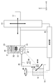
- the figure which shows an example of the structure of the surface texture measuring machine (roundness measuring machine) which concerns on 1st Embodiment The figure which shows an example of the posture of the displacement detector when measuring the displacement in the horizontal direction.
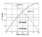
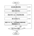
- Graph showing the relationship between the tilt angle of the stylus and the gain of the displacement detector Flow chart showing the procedure of measurement using a surface texture measuring machine (roundness measuring machine)
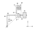
- the figure which shows an example of the structure of the displacement detector which concerns on 2nd Embodiment The figure which shows an example of the structure of the displacement detector which concerns on 3rd Embodiment
- FIG. 1 is a diagram showing an overall configuration of a surface texture measuring machine (roundness measuring machine) according to the first embodiment.
- the X-axis direction, the Y-axis direction, and the Z-axis direction are orthogonal to each other, the X-axis direction is the horizontal direction, the Y-axis direction is the horizontal direction orthogonal to the X-axis direction, and the Z-axis direction is the vertical direction (vertical).
- the surface texture measuring machine 10 includes a horizontal movement mechanism 12, a vertical movement mechanism 14, a rotary table 16, a displacement detector 20, and a control unit 50.
- the horizontal movement mechanism 12 is extended in the horizontal direction (X-axis direction in FIG. 1). One end of the horizontal movement mechanism 12 holds the displacement detector 20 detachably, and the other end of the horizontal movement mechanism 12 is held by the vertical movement mechanism 14. The horizontal movement mechanism 12 is moved in the horizontal direction by driving a motor (not shown).
- the vertical movement mechanism 14 is installed vertically on the main body base (not shown).
- the horizontal movement mechanism 12 is moved in the vertical direction along the vertical movement mechanism 14 by driving a motor (not shown) of the vertical movement mechanism 14.
- the horizontal and vertical positions of the displacement detector 20 are adjusted by the movement of the horizontal movement mechanism 12.
- the rotary table 16 is provided on the main body base. It is possible to finely feed the rotary table 16 in the X-axis direction and the Y-axis direction by using the X-axis direction fine movement knob (not shown) and the Y-axis direction fine movement knob (not shown). Further, the inclination of the rotary table 16 in the X-axis direction and the Y-axis direction is adjusted by the X-axis direction inclination knob (not shown) and the Y-axis direction inclination knob (not shown).
- the rotation stage 14 is rotated about a rotation axis parallel to the Z-axis direction by a motor (not shown) provided on the main body base.
- a work W to be measured is placed on the upper surface of the rotary table 16.
- the rotation axis of the rotary table 16 is parallel to the Z-axis direction.
- the work W is placed so that its central axis coincides with the rotation axis of the rotary table 16.
- the work W placed on the rotary table 16 is rotated around the rotary axis together with the rotary table 16.
- the control unit 50 includes a CPU (Central Processing Unit), a ROM (Read Only Memory), a RAM (Random Access Memory), an input / output interface, and the like (not shown).
- various programs such as a control program stored in the ROM are expanded in the RAM, and the programs expanded in the RAM are executed by the CPU, so that various arithmetic processes and controls are performed via the input / output interface. The process is executed.
- control unit 50 Although one control unit 50 is shown in FIG. 1, one control unit 50 may be divided into a plurality of control units for each function. Further, the position of the control unit 50 can be arbitrarily determined.
- the control unit 50 comprehensively controls the horizontal movement mechanism 12, the vertical movement mechanism 14, the rotary table 16, and the displacement detector 20 according to various programs such as a control program.
- the control unit 50 drives the horizontal movement mechanism 12, the vertical movement mechanism 14, and the rotary table 16 based on a user's instruction input via an input / output interface (not shown).
- the control unit 50 calibrates the displacement detector 20.
- the control unit 50 detects the measurement direction of the displacement detector 20 based on the drive directions of the horizontal movement mechanism 12 and the vertical movement mechanism 14 at the start of measurement. The various processes performed by the control unit 50 will be described in detail later.
- the displacement detector 20 includes a detector body 30 and a stylus 40.
- the detector main body 30 includes a displacement detecting unit 31, a measuring force applying unit 32, and a stylus holding unit 33.
- the LVDT will be described as an example of the displacement detection unit 31.
- the displacement detection unit 31 has a bobbin having a plurality of coils and a core.
- the bobbin is fixed to a fixed portion, for example, the detector body 30.
- One end of the core is connected to the stylus holding portion 33 and the other end is a free end. Since the configuration of the LVDT is known, detailed description thereof will be omitted.
- the stylus holding unit 33 is connected to the core of the displacement detecting unit 31.
- the other end of the stylus holding portion 33 holds the stylus 40 swingably (or rotatably).
- the stylus holding portion 33 has a bearing 34 at the other end, and holds the stylus 40 swingably with the bearing 34 as a rotation axis (swing center).
- the bearing 34 is, for example, various bearings.
- the stylus 40 is held swingably around a rotation axis parallel to the Y-axis direction.
- the displacement detection unit 31 detects the displacement amount and the displacement direction of the contact 44 by detecting the displacement amount and the displacement direction of the core position.
- the measuring force applying mechanism 32 applies a measuring force that acts (urges) the contact 44 toward the measuring surface to the stylus 40.
- the measuring force applying mechanism 32 has, for example, an elastic body.
- an elastic body will be described as a coil spring as an example.
- the coil spring may be a tension spring (pull spring) or a compression spring.
- One end of the coil spring of the measuring force applying mechanism 32 is connected to the stylus holding portion 33, and the other end of the coil spring is fixed to a fixed portion, for example, the detector main body 30.
- control unit 50 can automatically detect the direction (measurement direction) in which the displacement is measured by the displacement detector 20. The detection of the measurement direction will be described in detail later.
- the stylus 40 includes a stylus arm 42 and a contactor 44.
- the stylus arm 42 is, for example, substantially L-shaped, and includes a horizontal arm portion 45 extending in the X-axis direction and a vertical arm portion 46 extending in the Z-axis direction.
- the base end of the horizontal arm portion 45 is held by the stylus holding portion 33 of the displacement detector 20, and the tip of the horizontal arm portion 45 coincides with the base end of the vertical arm portion 46.
- the vertical arm portion 46 extends downward in the vertical direction from the tip of the horizontal arm portion 45, and a contactor 44 is provided at the tip of the vertical arm portion 46.
- the contactor 44 comes into contact with the measurement surface of the work W, and the position of the contactor 44 is displaced according to the displacement of the measurement surface.
- the shape and material of the contactor 44 are not particularly limited, and examples of the shape of the contactor 44 include a spherical shape, a hemispherical shape, a cylindrical shape, a disk shape, an ax shape, a conical shape, and a polygonal pyramid shape. Examples of the material of the contactor 44 include ruby, zirconia, ceramic and the like.
- the line connecting the center of the contactor 44 and the swing center of the stylus 40 (the center of the bearing 34) (line L shown by a single point chain line in FIG. 1) is an angle (inclination angle of the stylus 40) ⁇ with respect to the vertical line.
- the angle ⁇ is not particularly limited, but preferably the angle ⁇ is 30 ° to 60 °, more preferably the angle ⁇ is 38 ° to 52 °, and even more preferably the angle ⁇ is approximately 45 °. is there.
- FIG. 1 shows a case where the angle ⁇ is 45 ° as an example. The angle ⁇ will be described in detail later.
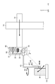
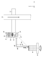
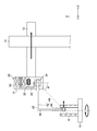
- the posture of the displacement detector 20 when measuring the displacement in the horizontal direction (X-axis direction) and the vertical direction (Z-axis direction) using the surface texture measuring machine 10 will be described with reference to FIGS. 2 to 4. .
- the hollow cylindrical work W will be described, but the purpose is not to limit the shape of the work W. 2 to 4 show the postures of the displacement detector 20 when measuring the roundness of the outer peripheral side surface, the flatness of the upper surface, and the roundness of the inner peripheral side surface, respectively.
- the stylus arm 42 can swing about the rotation axis parallel to the Y-axis direction by the bearing 34, so that the contact 44 swings on the XX plane. That is, the contactor 44 can be displaced in the X-axis direction and the Z-axis direction. Therefore, when measuring the displacement in the horizontal direction to measure the roundness of the outer peripheral side surface of the work W (FIG. 2), and when measuring the displacement in the horizontal direction to measure the flatness of the upper surface of the work W. With (FIG. 3), it is not necessary to change the posture of the displacement detector 20.
- the shape of the stylus arm 42 is also devised in order to reduce the trouble of changing the posture of the displacement detector 20. That is, since the stylus arm 42 is substantially L-shaped, the contactor 44 is not on the extension lines of the detector main body 30 in the X-axis direction and the Z-axis direction. Since there is no possibility that the detector main body 30 interferes with the work W, it is not necessary to change the posture of the displacement detector 20 even when measuring the roundness of the inner peripheral side surface of the work W (FIG. 4). This makes it possible to prevent a decrease in work efficiency due to a change in posture.
- the displacement detector 20 of the present embodiment uses a stylus 40 that is swingable (rotatable) about the Y-axis direction, the direction in which the contact 44 detected by the displacement detector 20 is displaced is , The direction is tangential to the arc centered on the rotation axis of the stylus 40. That is, the displacement of the contactor 44 includes an X-axis direction component and a Z-axis direction component. Therefore, the control unit 50 calculates the displacement amount (displacement amount in the X-axis direction or the displacement amount in the Z-axis direction) corresponding to the measurement direction based on the displacement amount of the contactor 44 and the angle ⁇ .
- the angle formed by the line connecting the center of the contact 44 and the rotation axis of the stylus 40 (line L indicated by the alternate long and short dash line in FIG. 1) and the vertical line is ⁇ .
- the contactor 44 swings so as to draw a minute arc, and the amount of change (angle change amount) of this angle ⁇ caused by the swing of the contactor 44 is defined as d ⁇ .
- the minute arc-shaped displacement of the contact 44 is a line segment perpendicular to the line connecting the center of the contact 44 and the rotation axis of the swing (that is, the arc). It can be approximated to a line segment in the tangential direction).
- the control unit 50 uses a triangular function to move the contact 44 on the XX plane.
- the amount of displacement can be decomposed into the amount of displacement in the horizontal direction (X-axis direction) and the amount of displacement in the vertical direction (Z-axis direction). More specifically, assuming that the length of the line segment in the tangential direction of the arc drawn by the contact 44 by swinging is D, the displacement amount in the X-axis direction is D ⁇ cos ⁇ , and the displacement amount in the Z-axis direction is D. ⁇ It can be calculated by sin ⁇ .
- the control unit 50 outputs the result of multiplying the displacement amount of the contactor 44 by cos ⁇ when measuring the displacement in the horizontal direction as a measurement result, and outputs the displacement amount of the contactor 44 when measuring the displacement in the vertical direction. Is multiplied by sin ⁇ and the result is output as the measurement result.
- the displacement detector 20 having one LVDT As described above, according to the present embodiment, it is possible to measure the displacement in two directions by using the displacement detector 20 having one LVDT. As a result, it is possible to realize simplification of the structure, reduction of manufacturing cost, and miniaturization of the device.
- the displacement detector 20 has only the bearing 34 as a movable part, and the number of movable parts is small (the degree of freedom of movement is 1). As a result, it is possible to reduce the occurrence of an error caused by the movable portion. Further, since the displacement detector 20 of the present embodiment has only one contactor, the degree of freedom of the posture of the displacement detector 20 and each direction are different from those of the invention of Patent Document 1 provided with two contacts. It is possible to improve the measurement accuracy of the displacement of.
- FIG. 5 is a graph showing the relationship between the angle ⁇ and the gain of the displacement detector 20, where the horizontal axis represents the angle ⁇ (unit: °) and the vertical axis represents the magnitude of the gain.
- the dotted line shows the gain in the X-axis direction
- the solid line shows the gain in the Z-axis direction.
- the gain corresponds to the displacement amount of the contactor 44, and in the graph of FIG. 5, the gain is shown as a relative value with 1 as the maximum value.
- the ratio of the component in the X-axis direction to the ratio of the component in the Z-axis direction is in the range of about 1: 0.58 to 1: 1.73, and the angle ⁇ . Is in the range of 30 ° to 60 °.
- the size of the angle ⁇ is determined so that the gain in the direction in which the measurement sensitivity becomes disadvantageous is about 60% or more of the maximum sensitivity (when the angle ⁇ is 0 (zero) °).
- the ratio of the component in the X-axis direction to the ratio of the component in the Z-axis direction is in the range of about 1: 0.75 to 1: 1.33, and the angle ⁇ . Ranges from about 38 ° to 52 °.
- the calibration of the displacement detector 20 will be described. For example, calibration is performed before shipment of the surface texture measuring machine 10. Even after shipment, calibration may be performed as necessary and the calibration value may be updated. In the present embodiment, since the displacement detector 20 measures the displacement in two directions using one LVDT, calibration is performed in each of the two measurement directions.
- data showing the correlation between the actual displacement amount (known) and the signal amount obtained by the displacement detection unit 31 is acquired in each of the X-axis direction and the Z-axis direction.
- Examples of the data showing the correlation include a calibration value table and a calibration curve.
- a gain at which a good signal amount can be obtained is determined as a calibration value based on the data showing this correlation.
- the calibration value used when measuring the inner peripheral side surface may be further determined.
- the determined calibration value is stored in, for example, a memory (not shown) provided in the control unit 50.
- the type of memory is not particularly limited, but for example, the memory is ROM or RAM.
- the displacement detector 20 of the present embodiment can measure with high accuracy in any measurement direction.
- FIG. 6 is a flowchart showing the measurement procedure.
- the control unit 50 moves the displacement detector 20 by using the horizontal movement mechanism 12 and the vertical movement mechanism 14, and brings the contact 44 into contact with the measurement surface of the work W (step S10).
- control unit 50 automatically detects the measurement direction based on the drive directions of the horizontal movement mechanism 12 and the vertical movement mechanism 14 (step S12).
- automatic detection of the measurement direction in the present embodiment will be described with reference to FIGS. 2 to 4.
- a hollow cylindrical work W will be described as an example, but the purpose is not to limit the shape of the work W.
- the control unit 50 drives the horizontal movement mechanism 12 in the negative direction of the X-axis (horizontally toward the left side in FIG. 2).
- the contactor 44 is brought into contact with the outer peripheral side surface of the work W on the rotary table 16.
- the displacement detection unit 31 detects the displacement of the contactor 44.
- the control unit 50 measures the displacement (outer diameter) in the X-axis direction. Detect automatically. In the state shown in FIG. 2, when the straightness of the outer peripheral side surface is measured while moving the vertical movement mechanism 14 in the Z-axis direction, the measurement direction can be detected in the same manner.
- the control unit 50 drives the vertical movement mechanism 14 in the negative direction of the Z axis (vertically downward in FIG. 2).
- the contactor 44 is brought into contact with the upper surface of the work W on the rotary table 16.
- the displacement detection unit 31 detects the displacement of the contactor 44.
- the control unit 50 automatically detects that the displacement in the Z axis direction is measured. To do.
- the straightness of the upper surface is measured while moving the horizontal movement mechanism 12 in the X-axis direction in the state shown in FIG. 3, the measurement direction can be detected in the same manner.
- the control unit 50 drives the horizontal movement mechanism 12 in the positive direction of the X-axis (horizontally toward the right side in FIG. 4).
- the contactor 44 is brought into contact with the inner side surface of the work W on the rotary table 16.
- the displacement detection unit 31 detects the displacement of the contactor 44. Based on the fact that the displacement of the contact 44 is detected when the horizontal movement mechanism 12 is driven in the positive direction of the X-axis, the displacement detection unit 31 measures the displacement (inner diameter direction) in the X-axis direction. Is automatically detected.
- the measurement direction can be detected in the same manner.
- the measurement direction is automatically set based on which direction the horizontal movement mechanism 12 or the vertical movement mechanism 14 is driven at the start of measurement when the contactor 44 comes into contact with the work W. Can be detected. Thereby, the efficiency of measurement can be improved.
- the control unit 50 reads out the calibration value according to the detected measurement direction from the memory and sets it (step S14), and measures the displacement of the contact 44 (step S16).
- the displacement detection unit 31 when measuring the roundness of the outer peripheral side surface of the columnar work W, the displacement detection unit 31 measures the displacement of the contact 44 while rotating the rotary table 16 (and the work W) in the state shown in FIG. .. Further, for example, when measuring the straightness of the outer peripheral side surface of the work W, the displacement detection unit 31 drives the vertical movement mechanism 14 to move the detector main body 30 in the Z-axis direction in the state shown in FIG. Measure the displacement of 44.
- the displacement of the contact 44 is measured by the displacement detection unit 31 while rotating the rotary table 16 (and the work W) in the state shown in FIG. Further, for example, when measuring the straightness of the upper surface of the work W, the displacement detection unit 31 drives the horizontal movement mechanism 12 to move the detector main body 30 in the X-axis direction in the state shown in FIG. Measure the displacement of.
- the displacement detection unit 31 moves the contact 44 while rotating the rotary table 16 (and the work W) in the state shown in FIG. Measure the displacement.
- the vertical movement mechanism 14 is driven in the state shown in FIG. 4 to move the detector main body 30 in the Z-axis direction while contacting with the displacement detection unit 31. The displacement of the child 44 is measured.
- the displacement amount of the contactor 44 includes the X-axis direction component and the Z-axis direction component. Therefore, the control unit 50 uses the displacement amount of the contactor 44 measured by the displacement detection unit 31 as the displacement amount in the measurement direction. The calculation is performed to convert to, and the calculation result is output as the measurement result (step S18). Specifically, when measuring the displacement in the X-axis direction (horizontal direction), the control unit 50 calculates the displacement amount in the X-axis direction by multiplying the displacement amount of the contactor 44 by cos ⁇ . The result is output as a measurement result.
- control unit 50 calculates the displacement amount in the Z-axis direction by multiplying the displacement amount of the contactor 44 by sin ⁇ , and measures the calculated result. Output as a result.
- step S18 when measuring in another direction (step S20: Yes), the process returns to step S10.
- step S20 when changing the measurement direction, it is not necessary to change the posture of the displacement detector 20 in this embodiment, so that the measurement can be performed efficiently. If the measurement is not performed in the other direction (step S20: No), the measurement is terminated.
- the stylus 40 capable of swinging on the XX plane with the bearing 34 as the swing center is used. Since the line connecting the center of the contactor 44 and the rotation axis of the stylus 40 forms a predetermined angle ⁇ with respect to the vertical line, the direction from the swing center of the stylus 40 toward the contactor 44 (contactor direction) is Includes an X-axis direction component and a Z-axis direction component. Since the contactor 44 is displaced in a direction perpendicular to the direction from the rotation axis of the swing toward the contactor 44, the displacement of the contactor 44 also includes an X-axis direction component and a Z-axis direction component. Therefore, it is possible to measure the displacement in the X-axis direction and the Z-axis direction with the displacement detector 20 including one LVDT.
- the configuration of the displacement detector is different from that of the first embodiment.
- the displacement detector includes an elastic body instead of the bearing 34. Since the overall configuration of the surface texture measuring machine according to the second embodiment is basically the same as that of the first embodiment, the description thereof will be omitted.
- FIG. 7 shows the configuration of the displacement detector 60 according to the second embodiment.
- the displacement detector 60 includes a leaf spring 61 as an example of an elastic body. As shown in FIG. 7, one end of the leaf spring 61 is held by the spring holding member 62, and the spring holding member 62 is fixed to a fixing portion, for example, the detector main body 30. The other end of the leaf spring 61 is held by the spring holding member 63, and the spring holding member 63 is connected to the stylus holding portion 33.
- the immovable part of the configuration of the displacement detector 60 is shaded (shaded) so that it can be distinguished from the moving part.
- the stylus 40 is configured to swing around the substantially center of the leaf spring 61 (the center of the portion not held by the spring holding members 62 and 63) (the center of swing).
- the displacement is transmitted to the core of the displacement detection unit 31 via the stylus arm 42 and the stylus holding unit 33, and the displacement detection unit 31 detects this displacement. To do.
- the spring holding member 63 is movable, but the spring holding member 62 is immovable. Therefore, as a result of the displacement of the position of the contactor 44, when the leaf spring 61 is displaced (deformed) from the neutral point, a reaction force is generated by the leaf spring 61. Since the direction in which this reaction force acts is opposite to the direction in which the contactor 44 is displaced, the reaction force acts to press the contactor 44 against the measurement surface. Since this reaction force plays the role of the measuring force by the measuring force applying mechanism 32 in the first embodiment, the measuring force applying mechanism 32 can be eliminated in the second embodiment. This makes it possible to further simplify the configuration of the displacement detector 60.
- the displacement detector includes an elastic body instead of the bearing 34. Since the overall configuration of the surface texture measuring machine according to the third embodiment is basically the same as that of the first embodiment, the description thereof will be omitted.
- FIG. 8 shows the configuration of the displacement detector 70 according to the third embodiment.
- the displacement detector 70 includes a cross spring 71 as an example of an elastic body. As shown in FIG. 8, two of the four ends of the cross spring 71 are held by the spring holding member 72, and the spring holding member 72 is fixed to a fixing portion, for example, the detector main body 30. The remaining two ends of the four ends of the cross spring 71 are held by the spring holding member 73, and the spring holding member 73 is connected to the stylus holding portion 33.
- the immovable part of the configuration of the displacement detector 70 is shaded (shaded) so that it can be distinguished from the moving part.
- the stylus 40 is configured to be swingable with the center of the cross spring 71 (intersection of the cross) as the center (center of swing).
- the displacement is transmitted to the core of the displacement detection unit 31 via the stylus arm 42 and the stylus holding unit 33, so that the displacement detection unit 31 can detect the displacement. it can.
- the spring holding member 73 is movable, but the spring holding member 72 is immovable.
- a reaction force is generated by the cross spring 71. Similar to the second embodiment, in the third embodiment, since this reaction force plays the role of the measuring force by the measuring force applying mechanism 32 in the first embodiment, the measuring force applying mechanism 32 can be eliminated.
- the displacement detector includes a counterweight instead of the measuring force applying mechanism 32. Since the overall configuration of the surface texture measuring machine according to the fourth embodiment is basically the same as that of the first embodiment, the description thereof will be omitted.
- FIG. 9 shows the configuration of the displacement detector 80 according to the fourth embodiment.
- the displacement detector 80 includes a counterweight 81 on the side opposite to the stylus 40 when viewed from the bearing 34.
- the counterweight 81 swings in the direction opposite to the swing direction of the stylus 40.
- the number of movable parts of the displacement detectors 20, 60, 70 and 80 is small (because the degree of freedom of movement is low), it is possible to reduce the occurrence of errors due to the movable parts. Moreover, since the calibration value is set for each measurement direction, it is possible to measure with high accuracy in any measurement direction.
- the measurement direction can be automatically detected based on the movement direction of the drive mechanism (horizontal movement mechanism 12 and vertical movement mechanism 14) at the start of measurement, the measurement efficiency can be improved.
Landscapes
- Physics & Mathematics (AREA)
- General Physics & Mathematics (AREA)
- A Measuring Device Byusing Mechanical Method (AREA)
Abstract
Description
図1は、第1実施形態に係る表面性状測定機(真円度測定機)の全体構成を示す図である。なお、X軸方向、Y軸方向、及びZ軸方向は互いに直交する方向であり、X軸方向は水平方向、Y軸方向はX軸方向に直交する水平方向、Z軸方向は上下方向(鉛直方向)である。図1に示すように、表面性状測定機10は、水平移動機構12、垂直移動機構14、回転テーブル16、変位検出器20及び制御部50を備える。
以下の第2実施形態では変位検出器の構成が第1実施形態と異なる。具体的には、第2実施形態では変位検出器は軸受34の代わりに弾性体を備える。第2実施形態に係る表面性状測定機の全体構成は基本的に第1実施形態と同じであるため、説明を省略する。図7は第2実施形態に係わる変位検出器60の構成を示す。
第2実施形態と同様に第3実施形態でも、変位検出器は軸受34の代わりに弾性体を備える。第3実施形態に係る表面性状測定機の全体構成は基本的に第1実施形態と同じであるため、説明を省略する。図8は第3実施形態に係わる変位検出器70の構成を示す。
第4実施形態では、変位検出器は測定力付与機構32の代わりにカウンターウェイトを備える。第4実施形態に係る表面性状測定機の全体構成は基本的に第1実施形態と同じであるため、説明を省略する。図9は第4実施形態に係わる変位検出器80の構成を示す。
以上説明したように、各実施形態に係わる変位検出器20,60,70及び80は1つの変位検出部31のみを有するため、より単純な構成で2方向の変位を測定可能である。これにより、変位検出器20,60,70及び80の製造コストを低減することが可能となる。
Claims (17)
- 検出器本体と、
測定対象物の被測定面に接触する接触子を有するスタイラスと、
前記検出器本体に設けられ、互いに直交する第1方向及び第2方向を含む面を揺動面として前記スタイラスを揺動可能に保持するスタイラス保持部と、
前記検出器本体に設けられ、前記接触子と前記被測定面との接触に伴う前記接触子の変位を検出する変位検出部と、
を備え、
前記スタイラスは、
第1一端部と第1他端部とを有し、前記第1一端部が前記スタイラス保持部に保持され、前記第1一端部から前記第1他端部に向かって前記第1方向に延びる第1アームと、
第2一端部と第2他端部とを有し、前記第2一端部が前記第1他端部に接続され、前記第2一端部から前記第2他端部に向かって前記第2方向に延び、前記第2他端部に前記接触子が設けられた第2アームと、
を有する、変位検出器。 - 前記スタイラスは、前記スタイラス保持部を介して前記揺動面に直交する回転軸を中心に揺動可能に軸支される、請求項1に記載の変位検出器。
- 前記接触子を前記被測定面に向かう方向に付勢する力を付与する測定力付与部を備える、請求項2に記載の変位検出器。
- 前記スタイラス保持部は前記検出器本体に弾性体を介して揺動可能に取り付けられる、請求項1に記載の変位検出器。
- 前記スタイラスの揺動中心から前記接触子に向かう方向を接触子方向とした場合、前記接触子方向は、前記第1方向の成分と前記第2方向の成分とを有する、請求項1から4のいずれか1項に記載の変位検出器。
- 前記接触子が前記被測定面に接触しない状態において、前記第1方向の成分と前記第2方向の成分との比は1:0.58から1:1.73までの範囲内にある、請求項5に記載の変位検出器。
- 前記接触子が前記被測定面に接触しない状態において、前記第1方向の成分と前記第2方向の成分との比は1:0.75から1:1.33までの範囲内にある、請求項5に記載の変位検出器。
- 前記接触子が前記被測定面に接触しない状態において、前記第1方向の成分と前記第2方向の成分とが等しい、請求項5に記載の変位検出器。
- 前記接触子が変位した場合、前記変位検出部は、前記接触子の変位として前記第1方向の変位と前記第2方向の変位とを検出可能である、請求項1から8のいずれか1項に記載の変位検出器。
- 前記変位検出部は前記第1方向及び前記第2方向それぞれについて校正値を有する、請求項1から9のいずれか1項に記載の変位検出器。
- 前記変位検出部は、コアと複数のコイルと有する差動変圧器を備え、
前記スタイラス保持部は、揺動中心からみて前記スタイラスを支持する側とは反対側の端部において前記コアを支持する、
請求項1から10のいずれか1項に記載の変位検出器。 - 請求項1から11のいずれか1項に記載の変位検出器と、
前記変位検出器を保持し、且つ、水平方向及び前記水平方向に対して直交する鉛直方向に測定対象物に対して相対的に前記変位検出器を移動させる移動機構と、
を備える表面性状測定機。 - 測定開始時に前記変位検出器の接触子が前記測定対象物に接触した際の前記移動機構の移動方向に基づいて前記変位検出器の測定方向を検出する制御部を更に備える、
請求項12に記載の表面性状測定機。 - 前記制御部は、前記移動機構の駆動を制御する信号に基づいて前記変位検出器の測定方向を検出する、請求項13に記載の表面性状測定機。
- 請求項1から11のいずれか1項に記載の変位検出器と、
鉛直方向に対して平行なステージ回転軸周りに測定対象物を回転させる回転ステージと、
を備える真円度測定機。 - 前記変位検出器を保持し、且つ、水平方向及び前記水平方向に対して直交する鉛直方向に測定対象物に対して相対的に前記変位検出器を移動させる移動機構と、
測定開始時に前記変位検出器の接触子が前記測定対象物に接触した際の前記移動機構の移動方向に基づいて前記変位検出器の測定方向を検出する制御部を更に備える、
請求項15に記載の真円度測定機。 - 前記制御部は、前記移動機構の駆動を制御する信号に基づいて前記変位検出器の測定方向を検出する、請求項16に記載の真円度測定機。
Priority Applications (6)
| Application Number | Priority Date | Filing Date | Title |
|---|---|---|---|
| GB2107595.7A GB2596225B (en) | 2019-04-16 | 2020-04-03 | Displacement detector, surface shape measuring apparatus, and roundness measuring apparatus |
| CN202211161378.0A CN115574691A (zh) | 2019-04-16 | 2020-04-03 | 位移检测器、表面性状测定仪及真圆度测定仪 |
| CN202080008208.1A CN113272619A (zh) | 2019-04-16 | 2020-04-03 | 位移检测器、表面性状测定仪及真圆度测定仪 |
| DE112020001949.7T DE112020001949B4 (de) | 2019-04-16 | 2020-04-03 | Verschiebungsdetektor, Oberflächenform-Messvorrichtung und Rundheitsmessvorrichtung |
| CN202511465593.3A CN121323454A (zh) | 2019-04-16 | 2020-04-03 | 位移检测器、表面性状测定仪及真圆度测定仪 |
| US17/336,794 US11435175B2 (en) | 2019-04-16 | 2021-06-02 | Displacement detector, surface shape measuring apparatus, and roundness measuring apparatus |
Applications Claiming Priority (2)
| Application Number | Priority Date | Filing Date | Title |
|---|---|---|---|
| JP2019077810A JP6788207B2 (ja) | 2019-04-16 | 2019-04-16 | 変位検出器、表面性状測定機、及び真円度測定機 |
| JP2019-077810 | 2019-04-16 |
Related Child Applications (1)
| Application Number | Title | Priority Date | Filing Date |
|---|---|---|---|
| US17/336,794 Continuation US11435175B2 (en) | 2019-04-16 | 2021-06-02 | Displacement detector, surface shape measuring apparatus, and roundness measuring apparatus |
Publications (1)
| Publication Number | Publication Date |
|---|---|
| WO2020213432A1 true WO2020213432A1 (ja) | 2020-10-22 |
Family
ID=72837779
Family Applications (1)
| Application Number | Title | Priority Date | Filing Date |
|---|---|---|---|
| PCT/JP2020/015305 Ceased WO2020213432A1 (ja) | 2019-04-16 | 2020-04-03 | 変位検出器、表面性状測定機、及び真円度測定機 |
Country Status (6)
| Country | Link |
|---|---|
| US (1) | US11435175B2 (ja) |
| JP (1) | JP6788207B2 (ja) |
| CN (3) | CN121323454A (ja) |
| DE (1) | DE112020001949B4 (ja) |
| GB (1) | GB2596225B (ja) |
| WO (1) | WO2020213432A1 (ja) |
Cited By (1)
| Publication number | Priority date | Publication date | Assignee | Title |
|---|---|---|---|---|
| US11435175B2 (en) * | 2019-04-16 | 2022-09-06 | Tokyo Seimitsu Co., Ltd. | Displacement detector, surface shape measuring apparatus, and roundness measuring apparatus |
Families Citing this family (3)
| Publication number | Priority date | Publication date | Assignee | Title |
|---|---|---|---|---|
| KR101944080B1 (ko) * | 2018-07-24 | 2019-01-30 | 황재은 | 형상측정기 |
| JP2023018515A (ja) * | 2021-07-27 | 2023-02-08 | 株式会社ミツトヨ | 真円度測定機 |
| JP7792565B2 (ja) * | 2022-03-30 | 2025-12-26 | 株式会社東京精密 | 拡張保持リング検査治具 |
Citations (5)
| Publication number | Priority date | Publication date | Assignee | Title |
|---|---|---|---|---|
| JPH06273104A (ja) * | 1993-03-17 | 1994-09-30 | Mitsubishi Materials Corp | 輪郭形状測定機 |
| JPH07505958A (ja) * | 1992-09-25 | 1995-06-29 | カール−ツアイス−スチフツング | ワークにおける座標測定法 |
| WO2007097135A1 (ja) * | 2006-02-22 | 2007-08-30 | Tokyo Seimitsu Co., Ltd. | 変位検出器 |
| JP2018163093A (ja) * | 2017-03-27 | 2018-10-18 | 株式会社東京精密 | 検出器、表面性状測定機、及び真円度測定機 |
| JP2018173349A (ja) * | 2017-03-31 | 2018-11-08 | 株式会社東京精密 | 表面形状測定機の校正装置 |
Family Cites Families (28)
| Publication number | Priority date | Publication date | Assignee | Title |
|---|---|---|---|---|
| DE2937431C2 (de) * | 1979-09-15 | 1987-02-05 | Ernst Leitz Wetzlar Gmbh, 6330 Wetzlar | Einrichtung zur Meßwerterfassung an Prüflingen |
| CH658126A5 (de) * | 1983-03-07 | 1986-10-15 | Maag Zahnraeder & Maschinen Ag | Messgeraet und -verfahren zur teilungspruefung von zahnraedern. |
| DE3717666A1 (de) * | 1987-05-26 | 1988-12-08 | Hoefler Willy | Verfahren und vorrichtung zur pruefung des flankenprofils der zahnflanken von zahnraedern |
| CA2082708C (en) * | 1991-12-02 | 2004-01-13 | James Edward Randolph Jr. | Tool point compensation for hardware displacement and inclination |
| US5832416A (en) * | 1995-09-01 | 1998-11-03 | Brown & Sharpe Manufacturing Company | Calibration system for coordinate measuring machine |
| US5758429A (en) * | 1996-05-14 | 1998-06-02 | Farzan; Farshad | Translation and rotation coupled positioning method and apparatus |
| ATE524700T1 (de) | 2005-07-19 | 2011-09-15 | Behr Gmbh & Co Kg | Wärmeübertrager |
| JP2008256462A (ja) * | 2007-04-03 | 2008-10-23 | Fanuc Ltd | 形状データの画像表示方法 |
| JP2008292199A (ja) * | 2007-05-22 | 2008-12-04 | Mitsutoyo Corp | 真円度測定装置、真円度測定方法、及び真円度測定プログラム |
| JP4291382B2 (ja) * | 2007-07-31 | 2009-07-08 | ファナック株式会社 | 接触検知による取り付け誤差の自動補正機能を有する工作機械 |
| US8250772B2 (en) | 2008-02-07 | 2012-08-28 | Eaton Homer L | Spatial measurement and robotic arm device |
| JP4532577B2 (ja) * | 2008-05-23 | 2010-08-25 | ファナック株式会社 | 数値制御装置と機上計測装置を有する工作機械 |
| JP4653824B2 (ja) * | 2008-07-29 | 2011-03-16 | ファナック株式会社 | 機上計測装置にて計測対象物の形状を計測する工作機械システム |
| JP4968600B1 (ja) * | 2011-01-13 | 2012-07-04 | 株式会社東京精密 | 真円度測定装置及びその心ずれ量補正方法 |
| JP5639934B2 (ja) * | 2011-03-09 | 2014-12-10 | 株式会社ミツトヨ | 表面性状測定機 |
| US8701301B2 (en) * | 2011-04-19 | 2014-04-22 | Mitutoyo Corporation | Surface texture measuring instrument |
| CN104040288B (zh) * | 2012-01-04 | 2016-12-14 | 株式会社东京精密 | 轮廓形状表面粗糙度测定装置以及轮廓形状表面粗糙度测定方法 |
| CN104049114A (zh) | 2013-03-14 | 2014-09-17 | 鸿富锦精密工业(深圳)有限公司 | 电子器件量测治具及量测装置 |
| EP2990754B1 (en) | 2013-04-26 | 2017-10-11 | Tokyo Seimitsu Co., Ltd. | Shape measurement machine |
| JP6273104B2 (ja) * | 2013-07-22 | 2018-01-31 | ローム株式会社 | 日常生活における警告システム |
| JP6189153B2 (ja) * | 2013-09-18 | 2017-08-30 | 株式会社ミツトヨ | 梃子式測定器 |
| JP6518421B2 (ja) | 2014-09-24 | 2019-05-22 | 株式会社ミツトヨ | 真円度測定機およびその制御方法 |
| EP3527931B1 (en) * | 2015-01-30 | 2021-07-21 | Tokyo Seimitsu Co., Ltd. | Three-dimensional coordinate measurement apparatus |
| CN104965236A (zh) | 2015-06-12 | 2015-10-07 | 茅伟萍 | 具有探头的检测装置 |
| JP6671011B2 (ja) * | 2016-03-03 | 2020-03-25 | 株式会社東京精密 | 真円度測定装置 |
| CN109333156B (zh) | 2018-11-12 | 2019-11-26 | 电子科技大学 | 一种用于五轴数控机床rtcp检测的误差与姿态同步标定方法 |
| CN109848754B (zh) | 2019-02-25 | 2020-11-03 | 江苏大学 | 一种基于位移传感器的型材形状自动检测及姿态校正机构 |
| JP6788207B2 (ja) * | 2019-04-16 | 2020-11-25 | 株式会社東京精密 | 変位検出器、表面性状測定機、及び真円度測定機 |
-
2019
- 2019-04-16 JP JP2019077810A patent/JP6788207B2/ja active Active
-
2020
- 2020-04-03 CN CN202511465593.3A patent/CN121323454A/zh active Pending
- 2020-04-03 DE DE112020001949.7T patent/DE112020001949B4/de active Active
- 2020-04-03 GB GB2107595.7A patent/GB2596225B/en active Active
- 2020-04-03 WO PCT/JP2020/015305 patent/WO2020213432A1/ja not_active Ceased
- 2020-04-03 CN CN202080008208.1A patent/CN113272619A/zh active Pending
- 2020-04-03 CN CN202211161378.0A patent/CN115574691A/zh active Pending
-
2021
- 2021-06-02 US US17/336,794 patent/US11435175B2/en active Active
Patent Citations (5)
| Publication number | Priority date | Publication date | Assignee | Title |
|---|---|---|---|---|
| JPH07505958A (ja) * | 1992-09-25 | 1995-06-29 | カール−ツアイス−スチフツング | ワークにおける座標測定法 |
| JPH06273104A (ja) * | 1993-03-17 | 1994-09-30 | Mitsubishi Materials Corp | 輪郭形状測定機 |
| WO2007097135A1 (ja) * | 2006-02-22 | 2007-08-30 | Tokyo Seimitsu Co., Ltd. | 変位検出器 |
| JP2018163093A (ja) * | 2017-03-27 | 2018-10-18 | 株式会社東京精密 | 検出器、表面性状測定機、及び真円度測定機 |
| JP2018173349A (ja) * | 2017-03-31 | 2018-11-08 | 株式会社東京精密 | 表面形状測定機の校正装置 |
Cited By (1)
| Publication number | Priority date | Publication date | Assignee | Title |
|---|---|---|---|---|
| US11435175B2 (en) * | 2019-04-16 | 2022-09-06 | Tokyo Seimitsu Co., Ltd. | Displacement detector, surface shape measuring apparatus, and roundness measuring apparatus |
Also Published As
| Publication number | Publication date |
|---|---|
| DE112020001949B4 (de) | 2024-09-26 |
| DE112020001949T5 (de) | 2021-12-23 |
| CN121323454A (zh) | 2026-01-13 |
| GB2596225B (en) | 2023-01-25 |
| US20210285751A1 (en) | 2021-09-16 |
| GB2596225A (en) | 2021-12-22 |
| JP6788207B2 (ja) | 2020-11-25 |
| CN115574691A (zh) | 2023-01-06 |
| US11435175B2 (en) | 2022-09-06 |
| JP2020176871A (ja) | 2020-10-29 |
| CN113272619A (zh) | 2021-08-17 |
| GB202107595D0 (en) | 2021-07-14 |
Similar Documents
| Publication | Publication Date | Title |
|---|---|---|
| JP6788207B2 (ja) | 変位検出器、表面性状測定機、及び真円度測定機 | |
| JP6368986B1 (ja) | 検出器、表面性状測定機、及び真円度測定機 | |
| JP3075981B2 (ja) | 形状測定装置 | |
| JP4748287B2 (ja) | 形状測定装置 | |
| JP2005502876A (ja) | 表面形状測定装置 | |
| CN102227607A (zh) | 用于测量工件的方法、校准方法以及坐标测量仪其中考虑探测器的与方向相关的柔性 | |
| CN112119279A (zh) | 偏心测量装置 | |
| US20210010791A1 (en) | Method and Apparatus for Determining a Relative Position of an Axis of Rotation of a Rotary Table for a Coordinate Measuring Machine | |
| JP2024078405A (ja) | 測定システム及びその動作方法並びにスタイラス運動機構 | |
| JP5538882B2 (ja) | 表面特性を測定するための測定器 | |
| US12571622B2 (en) | Roundness measuring machine | |
| JP2019113378A (ja) | 回転角制限機構 | |
| JP2019045312A (ja) | スタイラス及び表面形状測定装置 | |
| JP7681822B2 (ja) | 校正ユニット、及び校正方法 | |
| JP4646520B2 (ja) | 3次元形状測定方法及び装置 | |
| JP2005010019A (ja) | 測定ヘッド | |
| JP4909562B2 (ja) | 表面性状測定装置 | |
| JP3787721B2 (ja) | 測定ヘッドにおける接触子の基準点検出方法 | |
| JP2000131054A (ja) | 回転軸の傾き測定方法及び傾き調整方法 | |
| JPS6222002A (ja) | 変位検出ヘツド | |
| JPH05141959A (ja) | ねじ有効径部振れ測定装置 | |
| WO2026028271A1 (ja) | 測定装置、駆動ユニット、測定システムおよび測定方法 | |
| JP2018048857A (ja) | 検出装置 | |
| JPH03500091A (ja) | 機械的部材の測定装置および測定方法 | |
| JP2005127839A (ja) | レンズ偏心測定装置 |
Legal Events
| Date | Code | Title | Description |
|---|---|---|---|
| 121 | Ep: the epo has been informed by wipo that ep was designated in this application |
Ref document number: 20791001 Country of ref document: EP Kind code of ref document: A1 |
|
| DPE2 | Request for preliminary examination filed before expiration of 19th month from priority date (pct application filed from 20040101) | ||
| ENP | Entry into the national phase |
Ref document number: 202107595 Country of ref document: GB Kind code of ref document: A Free format text: PCT FILING DATE = 20200403 |
|
| WWE | Wipo information: entry into national phase |
Ref document number: 2107595.7 Country of ref document: GB |
|
| 122 | Ep: pct application non-entry in european phase |
Ref document number: 20791001 Country of ref document: EP Kind code of ref document: A1 |
|
| WWG | Wipo information: grant in national office |
Ref document number: 2107595.7 Country of ref document: GB |