WO2020203830A1 - Matériau décoratif - Google Patents
Matériau décoratif Download PDFInfo
- Publication number
- WO2020203830A1 WO2020203830A1 PCT/JP2020/014174 JP2020014174W WO2020203830A1 WO 2020203830 A1 WO2020203830 A1 WO 2020203830A1 JP 2020014174 W JP2020014174 W JP 2020014174W WO 2020203830 A1 WO2020203830 A1 WO 2020203830A1
- Authority
- WO
- WIPO (PCT)
- Prior art keywords
- region
- pattern
- resin
- less
- base material
- Prior art date
Links
- 239000000463 material Substances 0.000 title claims abstract description 129
- 239000002537 cosmetic Substances 0.000 claims 2
- 230000007261 regionalization Effects 0.000 abstract 2
- 239000000758 substrate Substances 0.000 abstract 2
- 239000010410 layer Substances 0.000 description 73
- 229920005989 resin Polymers 0.000 description 47
- 239000011347 resin Substances 0.000 description 47
- 238000004049 embossing Methods 0.000 description 17
- 238000000034 method Methods 0.000 description 17
- 229910052751 metal Inorganic materials 0.000 description 16
- 239000002184 metal Substances 0.000 description 16
- 239000004575 stone Substances 0.000 description 12
- -1 polyethylene Polymers 0.000 description 11
- 230000003746 surface roughness Effects 0.000 description 8
- 239000003086 colorant Substances 0.000 description 7
- 239000000123 paper Substances 0.000 description 7
- 229920002803 thermoplastic polyurethane Polymers 0.000 description 7
- PPBRXRYQALVLMV-UHFFFAOYSA-N Styrene Chemical compound C=CC1=CC=CC=C1 PPBRXRYQALVLMV-UHFFFAOYSA-N 0.000 description 6
- 230000000052 comparative effect Effects 0.000 description 6
- 239000000976 ink Substances 0.000 description 6
- 230000005865 ionizing radiation Effects 0.000 description 6
- 239000003795 chemical substances by application Substances 0.000 description 5
- 238000007639 printing Methods 0.000 description 5
- 229920005992 thermoplastic resin Polymers 0.000 description 5
- 229920001187 thermosetting polymer Polymers 0.000 description 5
- 229920000178 Acrylic resin Polymers 0.000 description 4
- 239000004925 Acrylic resin Substances 0.000 description 4
- 229920000877 Melamine resin Polymers 0.000 description 4
- 229920000122 acrylonitrile butadiene styrene Polymers 0.000 description 4
- 238000010030 laminating Methods 0.000 description 4
- 239000007788 liquid Substances 0.000 description 4
- 238000004519 manufacturing process Methods 0.000 description 4
- 239000004579 marble Substances 0.000 description 4
- 238000005259 measurement Methods 0.000 description 4
- 239000000049 pigment Substances 0.000 description 4
- 239000011295 pitch Substances 0.000 description 4
- 229920005672 polyolefin resin Polymers 0.000 description 4
- 239000002344 surface layer Substances 0.000 description 4
- 239000004593 Epoxy Substances 0.000 description 3
- 239000004640 Melamine resin Substances 0.000 description 3
- GWEVSGVZZGPLCZ-UHFFFAOYSA-N Titan oxide Chemical compound O=[Ti]=O GWEVSGVZZGPLCZ-UHFFFAOYSA-N 0.000 description 3
- 239000013078 crystal Substances 0.000 description 3
- 238000010586 diagram Methods 0.000 description 3
- 238000011156 evaluation Methods 0.000 description 3
- 239000010438 granite Substances 0.000 description 3
- 238000000465 moulding Methods 0.000 description 3
- 238000007747 plating Methods 0.000 description 3
- 239000002023 wood Substances 0.000 description 3
- NIXOWILDQLNWCW-UHFFFAOYSA-M Acrylate Chemical compound [O-]C(=O)C=C NIXOWILDQLNWCW-UHFFFAOYSA-M 0.000 description 2
- VYZAMTAEIAYCRO-UHFFFAOYSA-N Chromium Chemical compound [Cr] VYZAMTAEIAYCRO-UHFFFAOYSA-N 0.000 description 2
- XEEYBQQBJWHFJM-UHFFFAOYSA-N Iron Chemical compound [Fe] XEEYBQQBJWHFJM-UHFFFAOYSA-N 0.000 description 2
- 239000004698 Polyethylene Substances 0.000 description 2
- 239000004743 Polypropylene Substances 0.000 description 2
- RTAQQCXQSZGOHL-UHFFFAOYSA-N Titanium Chemical compound [Ti] RTAQQCXQSZGOHL-UHFFFAOYSA-N 0.000 description 2
- BZHJMEDXRYGGRV-UHFFFAOYSA-N Vinyl chloride Chemical compound ClC=C BZHJMEDXRYGGRV-UHFFFAOYSA-N 0.000 description 2
- 229920002433 Vinyl chloride-vinyl acetate copolymer Polymers 0.000 description 2
- XECAHXYUAAWDEL-UHFFFAOYSA-N acrylonitrile butadiene styrene Chemical compound C=CC=C.C=CC#N.C=CC1=CC=CC=C1 XECAHXYUAAWDEL-UHFFFAOYSA-N 0.000 description 2
- 239000004676 acrylonitrile butadiene styrene Substances 0.000 description 2
- 150000001336 alkenes Chemical class 0.000 description 2
- 238000010538 cationic polymerization reaction Methods 0.000 description 2
- 238000010894 electron beam technology Methods 0.000 description 2
- 239000011888 foil Substances 0.000 description 2
- 238000007646 gravure printing Methods 0.000 description 2
- 229920000554 ionomer Polymers 0.000 description 2
- 239000011344 liquid material Substances 0.000 description 2
- 239000000178 monomer Substances 0.000 description 2
- JRZJOMJEPLMPRA-UHFFFAOYSA-N olefin Natural products CCCCCCCC=C JRZJOMJEPLMPRA-UHFFFAOYSA-N 0.000 description 2
- 229920001490 poly(butyl methacrylate) polymer Polymers 0.000 description 2
- 229920003229 poly(methyl methacrylate) Polymers 0.000 description 2
- 229920001707 polybutylene terephthalate Polymers 0.000 description 2
- 229920001225 polyester resin Polymers 0.000 description 2
- 239000004645 polyester resin Substances 0.000 description 2
- 229920000573 polyethylene Polymers 0.000 description 2
- 229920000139 polyethylene terephthalate Polymers 0.000 description 2
- 239000005020 polyethylene terephthalate Substances 0.000 description 2
- 239000004926 polymethyl methacrylate Substances 0.000 description 2
- 229920001155 polypropylene Polymers 0.000 description 2
- 239000004800 polyvinyl chloride Substances 0.000 description 2
- 238000010526 radical polymerization reaction Methods 0.000 description 2
- 239000002356 single layer Substances 0.000 description 2
- 229920002725 thermoplastic elastomer Polymers 0.000 description 2
- 239000010936 titanium Substances 0.000 description 2
- 229910052719 titanium Inorganic materials 0.000 description 2
- 235000010215 titanium dioxide Nutrition 0.000 description 2
- 229920006337 unsaturated polyester resin Polymers 0.000 description 2
- WZSFTHVIIGGDOI-UHFFFAOYSA-N 4,5,6,7-tetrachloro-3-[2-methyl-3-[(4,5,6,7-tetrachloro-3-oxoisoindol-1-yl)amino]anilino]isoindol-1-one Chemical compound ClC1=C(Cl)C(Cl)=C(Cl)C2=C1C(NC1=CC=CC(NC=3C4=C(C(=C(Cl)C(Cl)=C4Cl)Cl)C(=O)N=3)=C1C)=NC2=O WZSFTHVIIGGDOI-UHFFFAOYSA-N 0.000 description 1
- 241001482107 Alosa sapidissima Species 0.000 description 1
- 229910001369 Brass Inorganic materials 0.000 description 1
- RYGMFSIKBFXOCR-UHFFFAOYSA-N Copper Chemical compound [Cu] RYGMFSIKBFXOCR-UHFFFAOYSA-N 0.000 description 1
- 235000019738 Limestone Nutrition 0.000 description 1
- NRCMAYZCPIVABH-UHFFFAOYSA-N Quinacridone Chemical compound N1C2=CC=CC=C2C(=O)C2=C1C=C1C(=O)C3=CC=CC=C3NC1=C2 NRCMAYZCPIVABH-UHFFFAOYSA-N 0.000 description 1
- XTXRWKRVRITETP-UHFFFAOYSA-N Vinyl acetate Chemical compound CC(=O)OC=C XTXRWKRVRITETP-UHFFFAOYSA-N 0.000 description 1
- 229910000004 White lead Inorganic materials 0.000 description 1
- HCHKCACWOHOZIP-UHFFFAOYSA-N Zinc Chemical compound [Zn] HCHKCACWOHOZIP-UHFFFAOYSA-N 0.000 description 1
- NIXOWILDQLNWCW-UHFFFAOYSA-N acrylic acid group Chemical group C(C=C)(=O)O NIXOWILDQLNWCW-UHFFFAOYSA-N 0.000 description 1
- 239000000654 additive Substances 0.000 description 1
- 229920000180 alkyd Polymers 0.000 description 1
- 229910052782 aluminium Inorganic materials 0.000 description 1
- XAGFODPZIPBFFR-UHFFFAOYSA-N aluminium Chemical compound [Al] XAGFODPZIPBFFR-UHFFFAOYSA-N 0.000 description 1
- IRERQBUNZFJFGC-UHFFFAOYSA-L azure blue Chemical compound [Na+].[Na+].[Na+].[Na+].[Na+].[Na+].[Na+].[Na+].[Al+3].[Al+3].[Al+3].[Al+3].[Al+3].[Al+3].[S-]S[S-].[O-][Si]([O-])([O-])[O-].[O-][Si]([O-])([O-])[O-].[O-][Si]([O-])([O-])[O-].[O-][Si]([O-])([O-])[O-].[O-][Si]([O-])([O-])[O-].[O-][Si]([O-])([O-])[O-] IRERQBUNZFJFGC-UHFFFAOYSA-L 0.000 description 1
- 239000011230 binding agent Substances 0.000 description 1
- 230000015572 biosynthetic process Effects 0.000 description 1
- 239000000038 blue colorant Substances 0.000 description 1
- 239000010951 brass Substances 0.000 description 1
- 239000004566 building material Substances 0.000 description 1
- 229910052793 cadmium Inorganic materials 0.000 description 1
- BDOSMKKIYDKNTQ-UHFFFAOYSA-N cadmium atom Chemical compound [Cd] BDOSMKKIYDKNTQ-UHFFFAOYSA-N 0.000 description 1
- 239000006229 carbon black Substances 0.000 description 1
- 239000012461 cellulose resin Substances 0.000 description 1
- 238000006243 chemical reaction Methods 0.000 description 1
- 229910052804 chromium Inorganic materials 0.000 description 1
- 239000011651 chromium Substances 0.000 description 1
- 238000004140 cleaning Methods 0.000 description 1
- 229910017052 cobalt Inorganic materials 0.000 description 1
- 239000010941 cobalt Substances 0.000 description 1
- GUTLYIVDDKVIGB-UHFFFAOYSA-N cobalt atom Chemical compound [Co] GUTLYIVDDKVIGB-UHFFFAOYSA-N 0.000 description 1
- 238000004040 coloring Methods 0.000 description 1
- 239000002131 composite material Substances 0.000 description 1
- 238000001816 cooling Methods 0.000 description 1
- 229910052802 copper Inorganic materials 0.000 description 1
- 239000010949 copper Substances 0.000 description 1
- XCJYREBRNVKWGJ-UHFFFAOYSA-N copper(II) phthalocyanine Chemical compound [Cu+2].C12=CC=CC=C2C(N=C2[N-]C(C3=CC=CC=C32)=N2)=NC1=NC([C]1C=CC=CC1=1)=NC=1N=C1[C]3C=CC=CC3=C2[N-]1 XCJYREBRNVKWGJ-UHFFFAOYSA-N 0.000 description 1
- 238000005034 decoration Methods 0.000 description 1
- 239000000975 dye Substances 0.000 description 1
- 230000000694 effects Effects 0.000 description 1
- 150000002148 esters Chemical class 0.000 description 1
- 238000007667 floating Methods 0.000 description 1
- 230000005484 gravity Effects 0.000 description 1
- 239000012760 heat stabilizer Substances 0.000 description 1
- 238000007731 hot pressing Methods 0.000 description 1
- UCNNJGDEJXIUCC-UHFFFAOYSA-L hydroxy(oxo)iron;iron Chemical compound [Fe].O[Fe]=O.O[Fe]=O UCNNJGDEJXIUCC-UHFFFAOYSA-L 0.000 description 1
- 238000007641 inkjet printing Methods 0.000 description 1
- 229910052742 iron Inorganic materials 0.000 description 1
- 230000001788 irregular Effects 0.000 description 1
- 239000012948 isocyanate Substances 0.000 description 1
- 150000002513 isocyanates Chemical group 0.000 description 1
- 150000002576 ketones Chemical class 0.000 description 1
- RYZCLUQMCYZBJQ-UHFFFAOYSA-H lead(2+);dicarbonate;dihydroxide Chemical compound [OH-].[OH-].[Pb+2].[Pb+2].[Pb+2].[O-]C([O-])=O.[O-]C([O-])=O RYZCLUQMCYZBJQ-UHFFFAOYSA-H 0.000 description 1
- 239000004611 light stabiliser Substances 0.000 description 1
- 239000006028 limestone Substances 0.000 description 1
- 239000000314 lubricant Substances 0.000 description 1
- 239000010445 mica Substances 0.000 description 1
- 229910052618 mica group Inorganic materials 0.000 description 1
- 239000000203 mixture Substances 0.000 description 1
- 229910052759 nickel Inorganic materials 0.000 description 1
- PXHVJJICTQNCMI-UHFFFAOYSA-N nickel Substances [Ni] PXHVJJICTQNCMI-UHFFFAOYSA-N 0.000 description 1
- 239000004745 nonwoven fabric Substances 0.000 description 1
- 239000003973 paint Substances 0.000 description 1
- 238000010422 painting Methods 0.000 description 1
- 239000002245 particle Substances 0.000 description 1
- 230000002093 peripheral effect Effects 0.000 description 1
- 230000000704 physical effect Effects 0.000 description 1
- 239000004014 plasticizer Substances 0.000 description 1
- 239000011120 plywood Substances 0.000 description 1
- 238000005498 polishing Methods 0.000 description 1
- 229920002037 poly(vinyl butyral) polymer Polymers 0.000 description 1
- 229920005668 polycarbonate resin Polymers 0.000 description 1
- 239000004431 polycarbonate resin Substances 0.000 description 1
- 229920005862 polyol Polymers 0.000 description 1
- 150000003077 polyols Chemical group 0.000 description 1
- 229920000915 polyvinyl chloride Polymers 0.000 description 1
- 229910052573 porcelain Inorganic materials 0.000 description 1
- 239000000843 powder Substances 0.000 description 1
- 238000001556 precipitation Methods 0.000 description 1
- 238000002360 preparation method Methods 0.000 description 1
- 230000005855 radiation Effects 0.000 description 1
- 239000001062 red colorant Substances 0.000 description 1
- 239000011435 rock Substances 0.000 description 1
- 239000004576 sand Substances 0.000 description 1
- 238000007650 screen-printing Methods 0.000 description 1
- 238000007789 sealing Methods 0.000 description 1
- 229920002050 silicone resin Polymers 0.000 description 1
- 150000005846 sugar alcohols Polymers 0.000 description 1
- 239000004094 surface-active agent Substances 0.000 description 1
- 229920006230 thermoplastic polyester resin Polymers 0.000 description 1
- 239000004408 titanium dioxide Substances 0.000 description 1
- 239000006097 ultraviolet radiation absorber Substances 0.000 description 1
- 230000000007 visual effect Effects 0.000 description 1
- 239000001060 yellow colorant Substances 0.000 description 1
- 229910052725 zinc Inorganic materials 0.000 description 1
- 239000011701 zinc Substances 0.000 description 1
Images


Classifications
-
- E—FIXED CONSTRUCTIONS
- E04—BUILDING
- E04F—FINISHING WORK ON BUILDINGS, e.g. STAIRS, FLOORS
- E04F13/00—Coverings or linings, e.g. for walls or ceilings
- E04F13/07—Coverings or linings, e.g. for walls or ceilings composed of covering or lining elements; Sub-structures therefor; Fastening means therefor
- E04F13/08—Coverings or linings, e.g. for walls or ceilings composed of covering or lining elements; Sub-structures therefor; Fastening means therefor composed of a plurality of similar covering or lining elements
- E04F13/0871—Coverings or linings, e.g. for walls or ceilings composed of covering or lining elements; Sub-structures therefor; Fastening means therefor composed of a plurality of similar covering or lining elements having an ornamental or specially shaped visible surface
- E04F13/0873—Coverings or linings, e.g. for walls or ceilings composed of covering or lining elements; Sub-structures therefor; Fastening means therefor composed of a plurality of similar covering or lining elements having an ornamental or specially shaped visible surface the visible surface imitating natural stone, brick work, tiled surface or the like
-
- E—FIXED CONSTRUCTIONS
- E04—BUILDING
- E04F—FINISHING WORK ON BUILDINGS, e.g. STAIRS, FLOORS
- E04F13/00—Coverings or linings, e.g. for walls or ceilings
- E04F13/07—Coverings or linings, e.g. for walls or ceilings composed of covering or lining elements; Sub-structures therefor; Fastening means therefor
- E04F13/08—Coverings or linings, e.g. for walls or ceilings composed of covering or lining elements; Sub-structures therefor; Fastening means therefor composed of a plurality of similar covering or lining elements
- E04F13/0871—Coverings or linings, e.g. for walls or ceilings composed of covering or lining elements; Sub-structures therefor; Fastening means therefor composed of a plurality of similar covering or lining elements having an ornamental or specially shaped visible surface
-
- B—PERFORMING OPERATIONS; TRANSPORTING
- B29—WORKING OF PLASTICS; WORKING OF SUBSTANCES IN A PLASTIC STATE IN GENERAL
- B29C—SHAPING OR JOINING OF PLASTICS; SHAPING OF MATERIAL IN A PLASTIC STATE, NOT OTHERWISE PROVIDED FOR; AFTER-TREATMENT OF THE SHAPED PRODUCTS, e.g. REPAIRING
- B29C59/00—Surface shaping of articles, e.g. embossing; Apparatus therefor
- B29C59/02—Surface shaping of articles, e.g. embossing; Apparatus therefor by mechanical means, e.g. pressing
-
- B—PERFORMING OPERATIONS; TRANSPORTING
- B32—LAYERED PRODUCTS
- B32B—LAYERED PRODUCTS, i.e. PRODUCTS BUILT-UP OF STRATA OF FLAT OR NON-FLAT, e.g. CELLULAR OR HONEYCOMB, FORM
- B32B27/00—Layered products comprising a layer of synthetic resin
- B32B27/06—Layered products comprising a layer of synthetic resin as the main or only constituent of a layer, which is next to another layer of the same or of a different material
- B32B27/08—Layered products comprising a layer of synthetic resin as the main or only constituent of a layer, which is next to another layer of the same or of a different material of synthetic resin
-
- B—PERFORMING OPERATIONS; TRANSPORTING
- B32—LAYERED PRODUCTS
- B32B—LAYERED PRODUCTS, i.e. PRODUCTS BUILT-UP OF STRATA OF FLAT OR NON-FLAT, e.g. CELLULAR OR HONEYCOMB, FORM
- B32B27/00—Layered products comprising a layer of synthetic resin
- B32B27/30—Layered products comprising a layer of synthetic resin comprising vinyl (co)polymers; comprising acrylic (co)polymers
- B32B27/304—Layered products comprising a layer of synthetic resin comprising vinyl (co)polymers; comprising acrylic (co)polymers comprising vinyl halide (co)polymers, e.g. PVC, PVDC, PVF, PVDF
-
- B—PERFORMING OPERATIONS; TRANSPORTING
- B32—LAYERED PRODUCTS
- B32B—LAYERED PRODUCTS, i.e. PRODUCTS BUILT-UP OF STRATA OF FLAT OR NON-FLAT, e.g. CELLULAR OR HONEYCOMB, FORM
- B32B3/00—Layered products comprising a layer with external or internal discontinuities or unevennesses, or a layer of non-planar shape; Layered products comprising a layer having particular features of form
- B32B3/26—Layered products comprising a layer with external or internal discontinuities or unevennesses, or a layer of non-planar shape; Layered products comprising a layer having particular features of form characterised by a particular shape of the outline of the cross-section of a continuous layer; characterised by a layer with cavities or internal voids ; characterised by an apertured layer
- B32B3/30—Layered products comprising a layer with external or internal discontinuities or unevennesses, or a layer of non-planar shape; Layered products comprising a layer having particular features of form characterised by a particular shape of the outline of the cross-section of a continuous layer; characterised by a layer with cavities or internal voids ; characterised by an apertured layer characterised by a layer formed with recesses or projections, e.g. hollows, grooves, protuberances, ribs
-
- B—PERFORMING OPERATIONS; TRANSPORTING
- B44—DECORATIVE ARTS
- B44C—PRODUCING DECORATIVE EFFECTS; MOSAICS; TARSIA WORK; PAPERHANGING
- B44C1/00—Processes, not specifically provided for elsewhere, for producing decorative surface effects
- B44C1/24—Pressing or stamping ornamental designs on surfaces
-
- B—PERFORMING OPERATIONS; TRANSPORTING
- B44—DECORATIVE ARTS
- B44C—PRODUCING DECORATIVE EFFECTS; MOSAICS; TARSIA WORK; PAPERHANGING
- B44C5/00—Processes for producing special ornamental bodies
- B44C5/04—Ornamental plaques, e.g. decorative panels, decorative veneers
-
- B—PERFORMING OPERATIONS; TRANSPORTING
- B44—DECORATIVE ARTS
- B44F—SPECIAL DESIGNS OR PICTURES
- B44F9/00—Designs imitating natural patterns
- B44F9/04—Designs imitating natural patterns of stone surfaces, e.g. marble
-
- E—FIXED CONSTRUCTIONS
- E04—BUILDING
- E04F—FINISHING WORK ON BUILDINGS, e.g. STAIRS, FLOORS
- E04F13/00—Coverings or linings, e.g. for walls or ceilings
- E04F13/07—Coverings or linings, e.g. for walls or ceilings composed of covering or lining elements; Sub-structures therefor; Fastening means therefor
- E04F13/08—Coverings or linings, e.g. for walls or ceilings composed of covering or lining elements; Sub-structures therefor; Fastening means therefor composed of a plurality of similar covering or lining elements
- E04F13/0866—Coverings or linings, e.g. for walls or ceilings composed of covering or lining elements; Sub-structures therefor; Fastening means therefor composed of a plurality of similar covering or lining elements composed of several layers, e.g. sandwich panels or layered panels
-
- E—FIXED CONSTRUCTIONS
- E04—BUILDING
- E04F—FINISHING WORK ON BUILDINGS, e.g. STAIRS, FLOORS
- E04F15/00—Flooring
- E04F15/02—Flooring or floor layers composed of a number of similar elements
- E04F15/10—Flooring or floor layers composed of a number of similar elements of other materials, e.g. fibrous or chipped materials, organic plastics, magnesite tiles, hardboard, or with a top layer of other materials
- E04F15/105—Flooring or floor layers composed of a number of similar elements of other materials, e.g. fibrous or chipped materials, organic plastics, magnesite tiles, hardboard, or with a top layer of other materials of organic plastics with or without reinforcements or filling materials
-
- E—FIXED CONSTRUCTIONS
- E04—BUILDING
- E04F—FINISHING WORK ON BUILDINGS, e.g. STAIRS, FLOORS
- E04F15/00—Flooring
- E04F15/02—Flooring or floor layers composed of a number of similar elements
- E04F15/10—Flooring or floor layers composed of a number of similar elements of other materials, e.g. fibrous or chipped materials, organic plastics, magnesite tiles, hardboard, or with a top layer of other materials
- E04F15/107—Flooring or floor layers composed of a number of similar elements of other materials, e.g. fibrous or chipped materials, organic plastics, magnesite tiles, hardboard, or with a top layer of other materials composed of several layers, e.g. sandwich panels
-
- B—PERFORMING OPERATIONS; TRANSPORTING
- B32—LAYERED PRODUCTS
- B32B—LAYERED PRODUCTS, i.e. PRODUCTS BUILT-UP OF STRATA OF FLAT OR NON-FLAT, e.g. CELLULAR OR HONEYCOMB, FORM
- B32B2250/00—Layers arrangement
- B32B2250/02—2 layers
-
- B—PERFORMING OPERATIONS; TRANSPORTING
- B32—LAYERED PRODUCTS
- B32B—LAYERED PRODUCTS, i.e. PRODUCTS BUILT-UP OF STRATA OF FLAT OR NON-FLAT, e.g. CELLULAR OR HONEYCOMB, FORM
- B32B2250/00—Layers arrangement
- B32B2250/24—All layers being polymeric
- B32B2250/246—All polymers belonging to those covered by groups B32B27/32 and B32B27/30
-
- B—PERFORMING OPERATIONS; TRANSPORTING
- B32—LAYERED PRODUCTS
- B32B—LAYERED PRODUCTS, i.e. PRODUCTS BUILT-UP OF STRATA OF FLAT OR NON-FLAT, e.g. CELLULAR OR HONEYCOMB, FORM
- B32B2255/00—Coating on the layer surface
- B32B2255/10—Coating on the layer surface on synthetic resin layer or on natural or synthetic rubber layer
-
- B—PERFORMING OPERATIONS; TRANSPORTING
- B32—LAYERED PRODUCTS
- B32B—LAYERED PRODUCTS, i.e. PRODUCTS BUILT-UP OF STRATA OF FLAT OR NON-FLAT, e.g. CELLULAR OR HONEYCOMB, FORM
- B32B2255/00—Coating on the layer surface
- B32B2255/26—Polymeric coating
-
- B—PERFORMING OPERATIONS; TRANSPORTING
- B32—LAYERED PRODUCTS
- B32B—LAYERED PRODUCTS, i.e. PRODUCTS BUILT-UP OF STRATA OF FLAT OR NON-FLAT, e.g. CELLULAR OR HONEYCOMB, FORM
- B32B2307/00—Properties of the layers or laminate
- B32B2307/40—Properties of the layers or laminate having particular optical properties
- B32B2307/402—Coloured
- B32B2307/4023—Coloured on the layer surface, e.g. ink
-
- B—PERFORMING OPERATIONS; TRANSPORTING
- B32—LAYERED PRODUCTS
- B32B—LAYERED PRODUCTS, i.e. PRODUCTS BUILT-UP OF STRATA OF FLAT OR NON-FLAT, e.g. CELLULAR OR HONEYCOMB, FORM
- B32B2307/00—Properties of the layers or laminate
- B32B2307/40—Properties of the layers or laminate having particular optical properties
- B32B2307/412—Transparent
-
- B—PERFORMING OPERATIONS; TRANSPORTING
- B32—LAYERED PRODUCTS
- B32B—LAYERED PRODUCTS, i.e. PRODUCTS BUILT-UP OF STRATA OF FLAT OR NON-FLAT, e.g. CELLULAR OR HONEYCOMB, FORM
- B32B2307/00—Properties of the layers or laminate
- B32B2307/70—Other properties
- B32B2307/732—Dimensional properties
-
- B—PERFORMING OPERATIONS; TRANSPORTING
- B32—LAYERED PRODUCTS
- B32B—LAYERED PRODUCTS, i.e. PRODUCTS BUILT-UP OF STRATA OF FLAT OR NON-FLAT, e.g. CELLULAR OR HONEYCOMB, FORM
- B32B2451/00—Decorative or ornamental articles
-
- B—PERFORMING OPERATIONS; TRANSPORTING
- B44—DECORATIVE ARTS
- B44B—MACHINES, APPARATUS OR TOOLS FOR ARTISTIC WORK, e.g. FOR SCULPTURING, GUILLOCHING, CARVING, BRANDING, INLAYING
- B44B5/00—Machines or apparatus for embossing decorations or marks, e.g. embossing coins
- B44B5/02—Dies; Accessories
- B44B5/026—Dies
Definitions
- the present invention relates to a decorative material.
- Decorative materials are widely used as surface decoration materials for furniture, building materials, etc.
- a stone pattern layer is provided on a thermoplastic resin base material.
- transparent or translucent resin layers are laminated in order so as to cover the entire surface of the stone pattern layer, and the interface between the stone pattern layer and the resin layer is partitioned by a closed region and arranged between adjacent closed regions.
- a decorative sheet having a groove-like uneven pattern composed of a line group pattern in which the groove depth is 3 ⁇ m to 100 ⁇ m and the distance between the convex portions is 1 ⁇ m to 1000 ⁇ m.
- the object of the present disclosure is to provide a decorative material that can give a different appearance and feel to the expression of stone grain.
- One aspect of the present disclosure is a decorative material in which a concavo-convex pattern is formed, which comprises a base material and a pattern-forming layer having concavities and convexities provided on one surface of the base material.
- a plurality of regions distinguished by different surface shapes are arranged, and the plurality of regions include at least a first region, a second region, and a third region, and the first region has a rough surface shape.
- Arithmetic mean roughness Ra JIS B 0601-2001
- the second region is composed of a plurality of convex lines having a surface shape, and the convex lines have a width of 10 ⁇ m or more and 250 ⁇ m.
- height is greater than 3 ⁇ m and less than 350 ⁇ m
- pitch with adjacent convex lines is greater than 10 ⁇ m and less than 160 ⁇ m
- the surface shape of the third region is smooth
- the arithmetic mean roughness Ra JIS B 0601- 2001 is a decorative material having a size of less than 3 ⁇ m.
- the pattern forming layer may have a step. Further, this step may be formed along at least a part of the boundary between the plurality of regions.
- the base material may be transparent, and a layer having a pattern may be laminated on the side opposite to one side of the base material provided with the pattern forming layer.
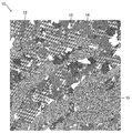
- FIG. 1 is an enlarged plan view showing a part of the surface of the decorative material 10.
- FIG. 2 is an enlarged diagram schematically showing a part of FIG. 1.
- FIG. 3 is a perspective view of the decorative material 10 schematically represented for explaining the morphology of the pattern forming layer 12.
- FIG. 4 is a view of a cut surface for explaining the second region 14.
- FIG. 5 is a perspective view of the decorative material 110 schematically shown for explaining the morphology of the pattern forming layer 112.
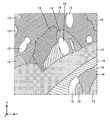
- FIG. 6 is a plan view showing the arrangement of steps in the form of the pattern forming layer 112.
- FIG. 7 is a diagram illustrating a scene in which irregularities are formed on the mold by a laser.
- FIG. 1 is an enlarged view (plan view) of a part of the decorative material 10 according to the first embodiment and viewed from the pattern forming layer 12 side.
- this figure excludes the expression by the pattern layer, and shows the pattern due to the unevenness generated in the pattern forming layer 12 in black and white shades. Therefore, in the actual decorative material 10, the pattern is not always formed by such shades.
- arrows (x, y, z) indicating directions, that is, coordinate systems, are also shown in FIGS. 1 and the following figures for convenience.
- the xy direction is the in-plane direction of the decorative material 10
- the z direction is the thickness direction. Therefore, FIG. 1 is a view (planar view) of the decorative material 10 on the pattern forming layer 12 side, particularly from the z direction.
- FIG. 2 a part of FIG. 1 is enlarged and schematically shown.
- FIG. 3 shows a perspective view schematically showing an enlarged part of the decorative material 10 in order to explain the configuration of the decorative material 10 in an easy-to-understand manner.
- the decorative material 10 in this embodiment has a base material 11 and a pattern forming layer 12 provided on one surface of the base material 11, and the pattern forming layer of the base material 11 is provided.
- the pattern layer 17, the colored layer 18, and the back surface layer 19 are laminated on the side opposite to the side on which the 12 is formed.
- the base material 11 and the pattern forming layer 12 can be laminated with separate layers, or a single layer can be used as both layers.
- the base material 11 and the pattern forming layer 12 are combined as a single layer, and one surface of the base material 11 ( In FIG. 3 and the like, the pattern forming layer 12 is formed by forming an uneven pattern near the surface of the surface on the + side of the z-axis).
- the base material 11 is a sheet-like member having a function of holding the pattern forming layer 12 and imparting strength to the decorative material 10.
- the form of the base material 11 may be a film, a sheet, or a plate. Generally, they are called films, sheets, and plates in order from those having a relatively thin thickness, but in this embodiment, the difference depending on the thickness form of these base materials is not an essential matter but an important matter. Absent. Therefore, the essence of the present invention and the interpretation of the claims remain unchanged even if any of the terms film, sheet, and plate is appropriately read as other terms in the present specification.
- the material 11 may have the same function as a conventionally known decorative material, the material is not particularly limited.
- the material of the base material is usually polyethylene, polypropylene, olefin-based thermoplastic elastomer, polyolefin-based resin such as ionomer, acrylic resin such as polymethylmethacrylate and polybutylmethacrylate, thermoplasticity such as polyethylene terephthalate and polybutylene terephthalate.
- Thermoplastic resin such as polyester resin, thermoplastic urethane resin, vinyl chloride resin, ABS resin (acrylonitrile-butadiene-styrene copolymer), styrene resin, melamine resin, unsaturated polyester resin, two-component curable urethane resin, etc.
- the material of the base material is resin, it may be colored with a known colorant.
- paper, non-woven fabric, metal, wood, etc. can also be used in the form of sheets, boards, three-dimensional objects, etc. by appropriately laminating them with the above resin materials.
- the base material 11 is made transparent so that the pattern of the pattern layer 17 appears. ..
- the thickness of the base material is not particularly limited, but in the case of a sheet-shaped base material or a film-shaped base material, for example, the thickness is about 20 ⁇ m or more and 1000 ⁇ m or less, and in the case of a plate-shaped base material, for example, 1 mm. Those having a size of 20 mm or less are used.
- the pattern forming layer 12 is provided on one surface of the base material 11 and is a layer that imparts an uneven pattern to the decorative material.
- the pattern forming layer 12 is particularly suitable for expressing a stone-grained uneven pattern on the decorative material 10. It is said that.
- the pattern forming layer 12 has the following form in this embodiment.
- the concavo-convex pattern includes the surface concavo-convex shapes of the first region 13, the second region 14, and the third region 15 having the surface concavo-convex shape peculiar to each individual as described below and illustrated in each drawing. It is a concavo-convex shape with a patterned pattern.
- the pattern forming layer 12 includes a first region 13, a second region 14, and a third region 15, and each region is arranged in a plurality of xy planes.
- the contour shape when each region is viewed from the z direction is not particularly limited, and may be a fixed shape or an indefinite shape. However, from the viewpoint of expressing the natural stone grain tone, the shape is irregular, and the decorative material 10 can be configured to have a flow in a predetermined direction when viewed as a whole. Further, the contour of the region and the boundary between the adjacent regions need not have a portion that borders the region, and may be naturally generated due to the difference in the pattern provided in the region as described later. From this point of view, in FIGS. 2 and 3, the outline of the region and the boundary between the adjacent regions are represented by dotted lines to distinguish them from the lines that actually exist.
- the first region 13 is a region having a surface having a so-called rough surface, sand grain, or matte surface, in which the surface uneven shape is formed by minute irregularities. Therefore, the first region 13 is a surface having minute irregularities with no large difference in surface roughness depending on the xy direction.
- the arithmetic average roughness Ra JIS B 0601-2001
- the surface may be 5 ⁇ m or more and 20 ⁇ m or less.
- the surface roughness can be configured to be within the range at the same measurement position regardless of the measurement direction.
- the adjacent region is the first region 13, and in that case, between the two adjacent first regions 13 so that the two adjacent regions can be visually distinguished from each other. It can also be configured so that the surface texture such as surface roughness is different from each other.
- the second region 14 is an region provided with a group of convex stripes in which a plurality of convex stripes 14a are arranged as a surface uneven shape.
- FIG. 4 shows a part of the cut surface of the decorative material 10 in the thickness direction (z direction) in the second region 14.
- FIG. 4 is a cross section in a direction orthogonal to the direction in which the convex line 14a extends. As shown in FIGS. 3 and 4, in the present embodiment, a plurality of convex streaks 14a extending linearly in the same direction are arranged inside a certain second region 14.
- the specific size of the height, width, and length of the convex line 14a is not particularly limited, but it may be fine from the viewpoint of forming a stone-grained uneven pattern in the decorative material. preferable.
- the convex line is preferably in the following form.
- the width W of the convex line (the size in the direction orthogonal to the direction in which the convex line extends in a plan view) is preferably 10 ⁇ m or more and less than 250 ⁇ m in the widest portion of the convex line. More preferably, it is 15 ⁇ m or more and 30 ⁇ m or less.
- the height H (magnitude in the z direction) of the convex line is preferably larger than 3 ⁇ m and less than 350 ⁇ m at the highest portion of the convex line. More preferably, it is 100 ⁇ m or more and 200 ⁇ m or less.
- the length of the convex line (the size in the direction in which the convex line extends) is determined by the size of the area.
- the plurality of convex lines in each region extend in the same direction in the region, but they do not necessarily have to be exactly parallel. Also, they do not necessarily have to be aligned in the same direction. However, it is preferable that the plurality of convex lines in each region extend in substantially the same direction in the region.
- the pitch P of adjacent convex stripes in the region is not particularly limited, but is preferably fine. Specifically, it can be larger than 10 ⁇ m and less than 160 ⁇ m, more preferably 25 ⁇ m or more and 70 ⁇ m or less.
- cross-sectional shape of the cross section orthogonal to the extending direction of the convex line 14a is not particularly limited and can be appropriately set.
- a quadrangle as in this embodiment for example, a semicircle, a semi-elliptical shape, a triangle, other polygons, an indefinite shape, and a composite shape thereof may be used.
- the adjacent region is the second region 14, and in that case, the direction in which the convex stripes extend in the adjacent second region 14, the width of the convex stripes, and the convex stripes.
- the height, the cross-sectional shape of the convex streaks, and at least one of the pitches of the plurality of convex streaks can be configured to be different. According to this, since various types of convex streaks are arranged, the shining portion changes depending on the viewing direction of the decorative material, and an appearance closer to the original stone grain can be obtained.
- the third region 15 is a region formed by a surface having a smoothed surface uneven shape.
- the arithmetic average roughness Ra (JIS B 0601-2001) of the surface can be less than 3 ⁇ m, and more preferably 1.5 ⁇ m or less. Further, the surface roughness can be configured to be within the range at the same measurement position regardless of the measurement direction.
- the pattern layer 17 is a layer on which a pattern (design) is applied, and in this embodiment, the pattern layer 17 is laminated on a surface of the base material 11 opposite to the surface provided with the pattern forming layer 12.
- the specific pattern in the pattern layer 17 is a cleaved pattern (consisting of a large number of single crystal particles) on the surface of a granite (granite) plate, granite, marble, sandstone, etc. to emphasize the impression of the stone surface.
- various patterns such as the surface of stone plates such as marble patterns and onix patterns represented by the surface or fracture surface of the rock plate, color patterns, photographs, paintings, drawings or geometric patterns can be arranged. it can.
- a "marble pattern” is a pattern that imitates marble, and is a pattern that looks like a flowing shape that is layered or kneaded in multiple colors. Examples include patterns using a drawing technique in which paint or ink is floated in a liquid with a heavy specific gravity and dyed with a floating pattern, such as so-called “suminagashi” or “marbling”.
- the "onix pattern” is a pattern that imitates a translucent limestone that shows a parallel striped structure due to precipitation.
- the pattern layer 17 can be a pattern that matches the uneven pattern formed by the pattern forming layer 12.
- the pattern may have a shape that matches the unevenness of the pattern forming layer 12, or may have a shape different from the unevenness of the pattern forming layer 12.
- the design of such a pattern layer 17 can be formed by an ink layer formed by printing such as gravure printing, silk screen printing, or ink jet printing.
- the ink constituting the pattern layer 17 may be appropriately selected from known inks according to the color tone of the pattern and the required physical properties.
- the binder resin for the ink include acrylic resin, vinyl chloride-vinyl acetate copolymer, cellulose resin, urethane resin, polyester resin, styrene resin, chlorinated polyolefin resin, polyvinyl butyral resin, alkyd resin, ketone resin, and epoxy.
- Resins, melamine resins, fluororesins, silicone resins, fibrous derivatives and the like can be used alone or in admixture of two or more.
- colorants examples include white colorants such as titanium white and zinc flower, black colorants such as carbon black (black), iron black, and azomethinazo pigments, yellow lead, titanium yellow, and polyazo.
- Yellow colorants such as yellow, isoindolinone yellow, nickel azo complex, red colorants such as petals, cadmium red, polyazo red, quinacridone red, blue colorants such as ultramarine, cobalt blue, phthalocyanine blue, aluminum, brass, etc.
- Colorants such as metal pigments made of scaly foil pieces, titanium dioxide-coated mica, and pearl pigments made of scaly foil pieces such as basic lead carbonate can be used.
- various additives such as a plasticizer, a surfactant, a heat stabilizer, an ultraviolet absorber, a light stabilizer, and a lubricant can be added in an appropriate amount, if necessary.
- the pattern forming layer 12 is formed on one surface of the base material 11, and the pattern layer 17 is laminated on the other surface on the opposite side, but the present invention is not limited to this.
- the pattern layer 17 may be formed on one side of the base material 11, and the pattern forming layer 12 may be provided.
- the colored layer 18 can be provided as needed when the pattern layer 17 is laminated on the side of the base material 11 opposite to the pattern forming layer 12, as in the present embodiment.
- the material of the colored layer 18 is not particularly limited, and for example, polyethylene, polypropylene, olefin-based thermoplastic elastomer, polyolefin-based resin such as ionomer, acrylic resin such as polymethylmethacrylate and polybutylmethacrylate, polyethylene terephthalate, polybutylene terephthalate and the like.
- thermoplastic polyester resin thermoplastic urethane resin, vinyl chloride resin, ABS resin (acrylonitrile-butadiene-styrene copolymer), thermoplastic resin such as styrene resin, melamine resin, unsaturated polyester resin, two-component curable urethane resin, etc.
- Thermosetting resin, or ionized radiation curable resin that is cured by ionizing radiation (ultraviolet rays, electron beams, etc.) with a monomer such as radical polymerization type acrylate type or cationic polymerization type epoxy type or prepolymer. It is used by coloring with a known colorant. Further, paper, metal, wood and the like can also be used in the form of a sheet, a plate, a three-dimensional object or the like by appropriately laminating with the base material 11.
- the back surface layer 19 can be provided as needed to improve the adhesion.
- the back surface layer 19 preferably contains a resin as a main component.
- the resin of the primer layer include ester resin, urethane resin, acrylic resin, polycarbonate resin, vinyl chloride-vinyl acetate copolymer and the like.
- the resin of the primer layer may be a two-component curable resin. Of these resins, a two-component curable resin is preferable from the viewpoint of adhesion.
- the two-component curable resin is not particularly limited as long as it is a resin that is cured by adding a curing agent to the main agent.
- the main agent is a polyol (polyhydric alcohol) and the curing agent is an isocyanate curing agent. Urethane resin is preferable.
- the thickness of the primer layer is usually about 0.5 ⁇ m or more and 20 ⁇ m or less, and may be in the range of 1 ⁇ m or more and 10 ⁇ m or less.
- the decorative material 10 of this embodiment includes at least all of the first region 13, the second region 14, and the third region 15. However, in all the areas of the decorative material, it is not necessary to be either the first area, the second area, or the third area, and the decorative material includes these first area, the second area, and the third area. It may contain regions of other shapes that do not satisfy any of the shapes of.
- the decorative material having the above composition it is possible to make the appearance and feel different from the conventional ones when expressing the stone grain.
- FIG. 5 is a diagram for explaining the decorative material 110 according to the second embodiment, and is a perspective view from the same viewpoint as the viewpoint of FIG.
- the pattern forming layer 112 includes the first region 13, the second region 14, and the third region 15, and a step is formed at the boundary of a part of the regions.
- a convex region 112a and a concave region 112b are provided. As a result, it becomes a decorative material that can give a different appearance and feel to the stone-grained expression.
- the difference in height (z direction) between the convex region 112a and the concave region 112b is not particularly limited, but may be about 10 ⁇ m or more and 100 ⁇ m or less, and may be about 20 ⁇ m or more and 60 ⁇ m or less.
- the number of steps may be two or more, that is, the first concave region lower than the convex region and the second lower than the first concave region with reference to the convex region.
- FIG. 6 shows the step in black and white as an example.
- the black portion is the convex region 112a
- the white portion is the concave region 112b.
- This is from the same viewpoint as in FIG. That is, in the decorative material 110 of this embodiment, there is a step due to the convex region 112a and the concave region 112b shown in FIG. 6 with respect to the first region 13, the second region 14, and the third region 15 shown in FIG. It is composed by combining.
- the manufacturing method described below includes a step of producing a manuscript image, a step of producing a block copy image, a step of producing a plate, and a step of forming a pattern forming layer.
- the pattern (stone-grained pattern) in the plan view to be expressed on the pattern forming layer 12 is acquired and used as the original image.
- the pattern in the plan view to be expressed on the surface of the base material 11 on the pattern forming layer 12 side is acquired as the image density (shading) and used as the block copy image.
- the plate image is preferably digital data
- pixels are generated in the two-dimensional coordinate plane (x, y) by using a method of reading the original image with a scanner and performing AD conversion. It is arranged, and each pixel obtains digital data corresponding to a unique density value. Further, when the original image is designed by using digital data by using CAD or the like from the beginning, the digital data can be used.
- the first region, the second region, and the third region are allocated to the digital data, and further, a binary image corresponding to the gradation image of the pattern is applied to each region by a conversion program from density to unevenness.
- the pattern of each area is generated and arranged on the two-dimensional virtual plane, and the block copy image is obtained as digital data.
- an embossed plate (molding mold for decorative material) having a plan-viewing pattern as shown in FIG. 1 on the surface is produced based on the block copy image.
- the manufacturing process of the uneven pattern comprises the following procedures (1) to (5).
- a metal roll 20 for embossing plate engraving as shown in FIG. 7 was prepared.
- the metal roll 20 is formed by plating a copper layer on the surface of a hollow iron cylinder having rotary drive shafts (shafts) 21 at both ends in the axial direction.
- the surface of the metal roll 20 was polished with a grindstone to roughen it, and a treatment was performed to prevent a decrease in engraving efficiency due to specular reflection of laser light for engraving.
- a laser beam direct engraving machine is used to engrave the surface of the metal roll 20 prepared in the step (2) based on the uneven pattern image data created in the step (1).
- the surface has the same plan-view shape as the uneven pattern on the surface of the decorative material as shown in FIG. 1, and the unevenness of the reverse unevenness (the portion corresponding to the convex line of the decorative material becomes a concave line on the embossed plate surface). Formed a shape. Therefore, the shape to be provided by the uneven pattern in the embossed plate is a mode in which the uneven relationship of the uneven pattern due to the convex lines in the above-mentioned decorative material is reversed, and can be considered in the same manner.
- the metal roll 20 is driven by an electric motor via the rotation drive shaft 21, and rotates around the rotation drive shaft 21 as a central axis.
- the surface of the metal roll 20 is scanned by the laser light P emitted from the laser head 22.
- the engraving liquid T is sprayed from the engraving liquid discharge port 23 onto the laser irradiation region on the surface of the metal roll 20. Irradiate with laser light.
- Electropolishing process After cleaning the engraving liquid, electrolytic polishing was performed to remove metal residues adhering to the surface of the metal roll 20.
- the decorative material 10 is obtained by embossing the base material 11 using the produced plate (embossed plate).
- the embossing may be performed by an appropriate known method, and is not particularly limited.
- a typical method of embossing is as follows, for example.
- a resin sheet made of a thermoplastic resin such as a polyolefin resin is used as the base material.
- This base material is heated and softened, and an embossed plate is pressed against the surface of the base material to form an uneven pattern on the surface of the embossed plate on the surface of the resin sheet.
- the resin sheet is cooled and solidified to fix the uneven pattern on the resin sheet.
- the resin sheet on which the uneven pattern is formed is released from the embossed plate.
- the various embossing methods will be further described, for example, the following methods (A) to (E).
- A The resin sheet as the base material is heated and softened, and the embossing plate is pressed to emboss.
- B Embossing and laminating by heat-sealing the resin sheet (base material) to be the surface sheet and the resin sheet (second base material) to be the base sheet by the heat pressure when the embossing plate is pressed. Embossing is performed by the doubling embossing method, which is performed at the same time.
- C A resin sheet (base material) to be used as a surface sheet is melt-extruded from a T-die and brought into contact with a cylinder-shaped embossed plate that also serves as a cooling roller to be embossed at the same time as the surface sheet is formed.
- the resin sheet (second base material) to be the base sheet inserted into the back surface side of the front surface sheet is further heat-sealed to perform doubling embossing at the same time as the film formation.
- D As disclosed in JP-A-57-87318, JP-A-7-32476, etc., an uncured liquid material of an ionizing radiation curable resin is applied to the surface of a cylinder-shaped embossed plate. Further, a base sheet made of a resin sheet or the like is laminated on the base sheet and irradiated with ionizing radiation to cure the uncured liquid material to obtain a cured product.
- a plurality of impregnated papers obtained by impregnating paper such as titanium paper with an uncured product of a thermosetting resin such as melamine resin on a backing material such as core paper or wood plywood. By hot-press molding the layers, each layer is laminated and integrated to produce a thermosetting resin decorative material. At that time, by inserting an embossing plate on the surface side of the impregnated paper, when the thermosetting resin is impregnated and cured to form a decorative material, the surface is embossed at the same time as hot pressing.
- thermoplastic resin is typically used as the material of the base material used in the embossing methods (A) to (C), and the material of the base material used in the embossing method of (D) is typically used.
- An ionizing radiation curable resin is used, and a thermosetting resin is typically used as the material of the base material used in the embossing method (E).
- the decorative material 10 can be obtained by printing the pattern layer 17 on the base material layer 11 and laminating the colored layer 18 and the back surface layer 19.
- the uses of the decorative materials described above are not particularly limited, but for example, interior materials for buildings such as walls, floors, and ceilings, outer walls, roofs, gates, walls, fences, and other exterior materials for buildings, doors, and windows. Fittings such as frames and door frames, surface materials for building members such as peripheral edges, skirting boards, and handrails, surface materials for home appliances such as TV receivers and refrigerators, and housings for office equipment such as copying machines, furniture such as porcelain Surface materials, boxes, surface materials for containers such as resin bottles, interior materials or exterior materials for vehicles, interior materials or exterior materials for ships, etc.
- the first region, the second region, and the third region were evaluated by changing their presence and mode.
- a pattern printing layer is first applied to a colored polyvinyl chloride (PVC) film having a thickness of 150 ⁇ m using a mixed resin ink of vinyl acetate and acrylic by a gravure printing method, and then the pattern is printed.
- a sheet was prepared.
- a transparent PVC film having a thickness of 300 ⁇ m was bonded to the pattern printing layer side of the produced pattern printing sheet by an embossing machine.
- the embossed plate was pressed at the same time to impart an uneven pattern of the pattern forming layer (conditions: machine speed 8 m / min, embossed plate temperature 80 ° C., embossed pressure 4.5 kgf).
- a desired decorative material was produced by the above steps.
- Table 1 The specific form and evaluation are shown in Table 1.
- the evaluation is a visual evaluation of the presence or absence of a natural texture for the decorative material of each example, with respect to the depth of stone grain and the brilliance of crystal grains, to any 20 adults under fluorescent lighting. I let you. The results were evaluated as good or bad. Ryo: More than 18 people answered that they had a natural texture. No: Less than 17 people answered that they had a natural texture.
Landscapes
- Engineering & Computer Science (AREA)
- Architecture (AREA)
- Civil Engineering (AREA)
- Structural Engineering (AREA)
- Mechanical Engineering (AREA)
- Laminated Bodies (AREA)
- Finishing Walls (AREA)
Abstract
La présente invention concerne un matériau décoratif pourvu d'un substrat et d'une couche de formation de motif ayant des renfoncements et des saillies qui sont disposés sur une surface du substrat, une pluralité de régions distinguées par des différences de forme de surface étant agencées dans la couche de formation de motif, la pluralité de régions étant pourvue d'au moins de premières régions, de deuxièmes régions et de troisièmes régions, les premières régions ayant une forme de surface rugueuse, dont la rugosité moyenne arithmétique Ra (JIS B 0601-2001) est de 5 µm à moins de 60 µm, les deuxièmes régions ayant une forme de surface dans laquelle une pluralité de stries en saillie sont agencées, les stries en saillie ayant une largeur de 10 µm à moins de 250 µm et une hauteur supérieure à 3 µm et inférieure à 350 µm, et le pas de stries en saillie adjacentes étant supérieur à 10 µm et inférieur à 160 µm, et la forme de surface des troisièmes régions étant lisse et ayant une rugosité moyenne arithmétique Ra (JIS B 0601-2001) inférieure à 3 µm.
Priority Applications (2)
| Application Number | Priority Date | Filing Date | Title |
|---|---|---|---|
| JP2021512036A JP7294408B2 (ja) | 2019-03-29 | 2020-03-27 | 化粧材 |
| US17/442,222 US20220170276A1 (en) | 2019-03-29 | 2020-03-27 | Decorative material |
Applications Claiming Priority (2)
| Application Number | Priority Date | Filing Date | Title |
|---|---|---|---|
| JP2019-066971 | 2019-03-29 | ||
| JP2019066971 | 2019-03-29 |
Publications (1)
| Publication Number | Publication Date |
|---|---|
| WO2020203830A1 true WO2020203830A1 (fr) | 2020-10-08 |
Family
ID=72668404
Family Applications (1)
| Application Number | Title | Priority Date | Filing Date |
|---|---|---|---|
| PCT/JP2020/014174 WO2020203830A1 (fr) | 2019-03-29 | 2020-03-27 | Matériau décoratif |
Country Status (3)
| Country | Link |
|---|---|
| US (1) | US20220170276A1 (fr) |
| JP (1) | JP7294408B2 (fr) |
| WO (1) | WO2020203830A1 (fr) |
Cited By (3)
| Publication number | Priority date | Publication date | Assignee | Title |
|---|---|---|---|---|
| JP2022055319A (ja) * | 2020-09-28 | 2022-04-07 | 大日本印刷株式会社 | 化粧シート、化粧材、版、および化粧シートの製造方法 |
| JP7197041B1 (ja) | 2022-03-11 | 2022-12-27 | 大日本印刷株式会社 | 化粧材用の賦型シート、化粧材用の転写シート、化粧材の製造方法 |
| WO2023231634A1 (fr) * | 2022-05-31 | 2023-12-07 | 比亚迪股份有限公司 | Pièce à travailler et dispositif électronique |
Citations (5)
| Publication number | Priority date | Publication date | Assignee | Title |
|---|---|---|---|---|
| JPH07256849A (ja) * | 1994-03-18 | 1995-10-09 | Dainippon Printing Co Ltd | 高意匠機能性化粧シート |
| JPH0852849A (ja) * | 1994-08-12 | 1996-02-27 | Dainippon Printing Co Ltd | 化粧シート及びその製造方法 |
| JPH08132581A (ja) * | 1994-11-02 | 1996-05-28 | Dainippon Printing Co Ltd | 化粧シート |
| JPH11268500A (ja) * | 1998-03-19 | 1999-10-05 | Dainippon Printing Co Ltd | 万線状凹凸模様を有する化粧材 |
| JP2001239627A (ja) * | 2000-02-29 | 2001-09-04 | Dainippon Printing Co Ltd | エンボス化粧シート |
Family Cites Families (3)
| Publication number | Priority date | Publication date | Assignee | Title |
|---|---|---|---|---|
| JP4319882B2 (ja) * | 2003-09-29 | 2009-08-26 | 大日本印刷株式会社 | 加飾シート、加飾成形品、及び射出成形同時加飾方法 |
| EP2328695A1 (fr) * | 2008-08-07 | 2011-06-08 | Uni-Pixel Displays, Inc. | Microstructures pour réduire l'apparition d'empreintes sur des surfaces |
| JP7067203B2 (ja) | 2018-03-30 | 2022-05-16 | 大日本印刷株式会社 | 化粧材 |
-
2020
- 2020-03-27 WO PCT/JP2020/014174 patent/WO2020203830A1/fr active Application Filing
- 2020-03-27 US US17/442,222 patent/US20220170276A1/en active Pending
- 2020-03-27 JP JP2021512036A patent/JP7294408B2/ja active Active
Patent Citations (5)
| Publication number | Priority date | Publication date | Assignee | Title |
|---|---|---|---|---|
| JPH07256849A (ja) * | 1994-03-18 | 1995-10-09 | Dainippon Printing Co Ltd | 高意匠機能性化粧シート |
| JPH0852849A (ja) * | 1994-08-12 | 1996-02-27 | Dainippon Printing Co Ltd | 化粧シート及びその製造方法 |
| JPH08132581A (ja) * | 1994-11-02 | 1996-05-28 | Dainippon Printing Co Ltd | 化粧シート |
| JPH11268500A (ja) * | 1998-03-19 | 1999-10-05 | Dainippon Printing Co Ltd | 万線状凹凸模様を有する化粧材 |
| JP2001239627A (ja) * | 2000-02-29 | 2001-09-04 | Dainippon Printing Co Ltd | エンボス化粧シート |
Cited By (6)
| Publication number | Priority date | Publication date | Assignee | Title |
|---|---|---|---|---|
| JP2022055319A (ja) * | 2020-09-28 | 2022-04-07 | 大日本印刷株式会社 | 化粧シート、化粧材、版、および化粧シートの製造方法 |
| JP7212870B2 (ja) | 2020-09-28 | 2023-01-26 | 大日本印刷株式会社 | 化粧シート、化粧材、版、および化粧シートの製造方法 |
| JP7197041B1 (ja) | 2022-03-11 | 2022-12-27 | 大日本印刷株式会社 | 化粧材用の賦型シート、化粧材用の転写シート、化粧材の製造方法 |
| WO2023171782A1 (fr) * | 2022-03-11 | 2023-09-14 | 大日本印刷株式会社 | Feuille mise en forme pour matériau décoratif, feuille de transfert pour matériau décoratif, et procédé de production de matériau décoratif |
| JP2023133015A (ja) * | 2022-03-11 | 2023-09-22 | 大日本印刷株式会社 | 化粧材用の賦型シート、化粧材用の転写シート、化粧材の製造方法 |
| WO2023231634A1 (fr) * | 2022-05-31 | 2023-12-07 | 比亚迪股份有限公司 | Pièce à travailler et dispositif électronique |
Also Published As
| Publication number | Publication date |
|---|---|
| JPWO2020203830A1 (fr) | 2020-10-08 |
| US20220170276A1 (en) | 2022-06-02 |
| JP7294408B2 (ja) | 2023-06-20 |
Similar Documents
| Publication | Publication Date | Title |
|---|---|---|
| WO2020203830A1 (fr) | Matériau décoratif | |
| US20210122138A1 (en) | Decorative material | |
| WO2019066026A1 (fr) | Matériau décoratif et moule pour matériau décoratif | |
| JP7294321B2 (ja) | 化粧材 | |
| JP2021142743A (ja) | 化粧材 | |
| JP7416054B2 (ja) | 化粧材及び化粧材の製造方法 | |
| CN111954594A (zh) | 装饰材料、装饰材料的制造方法 | |
| WO2021060530A1 (fr) | Matériau décoratif | |
| JP7268447B2 (ja) | 化粧材 | |
| WO2020067566A1 (fr) | Matériau cosmétique et feuille formée | |
| JP7386594B2 (ja) | 化粧材、化粧材の製造方法 | |
| JP7402600B2 (ja) | 化粧材 | |
| JP7139650B2 (ja) | 化粧材 | |
| JP7243031B2 (ja) | 化粧材 | |
| WO2020203737A1 (fr) | Matériau décoratif et son procédé de production | |
| JP2020157551A (ja) | 化粧材 | |
| JP7383222B2 (ja) | 化粧紙、化粧材、及び化粧紙の製造方法 | |
| JP3900622B2 (ja) | 化粧材及びその製造方法 | |
| JP7386593B2 (ja) | 化粧材、化粧材の製造方法 | |
| JP2022053812A (ja) | 化粧材 | |
| WO2020067568A1 (fr) | Matériau cosmétique et feuille formée | |
| JP4012297B2 (ja) | 合成樹脂製積層シート | |
| JP2024075728A (ja) | 化粧材 | |
| JP2021055530A (ja) | 化粧材 | |
| JP2022136462A (ja) | 化粧材 |
Legal Events
| Date | Code | Title | Description |
|---|---|---|---|
| 121 | Ep: the epo has been informed by wipo that ep was designated in this application |
Ref document number: 20784314 Country of ref document: EP Kind code of ref document: A1 |
|
| ENP | Entry into the national phase |
Ref document number: 2021512036 Country of ref document: JP Kind code of ref document: A |
|
| NENP | Non-entry into the national phase |
Ref country code: DE |
|
| 122 | Ep: pct application non-entry in european phase |
Ref document number: 20784314 Country of ref document: EP Kind code of ref document: A1 |