WO2020203245A1 - ショベル - Google Patents
ショベル Download PDFInfo
- Publication number
- WO2020203245A1 WO2020203245A1 PCT/JP2020/011622 JP2020011622W WO2020203245A1 WO 2020203245 A1 WO2020203245 A1 WO 2020203245A1 JP 2020011622 W JP2020011622 W JP 2020011622W WO 2020203245 A1 WO2020203245 A1 WO 2020203245A1
- Authority
- WO
- WIPO (PCT)
- Prior art keywords
- pump
- boom
- excavator
- hydraulic
- controller
- Prior art date
Links
Images
Classifications
-
- E—FIXED CONSTRUCTIONS
- E02—HYDRAULIC ENGINEERING; FOUNDATIONS; SOIL SHIFTING
- E02F—DREDGING; SOIL-SHIFTING
- E02F9/00—Component parts of dredgers or soil-shifting machines, not restricted to one of the kinds covered by groups E02F3/00 - E02F7/00
- E02F9/20—Drives; Control devices
- E02F9/22—Hydraulic or pneumatic drives
- E02F9/2221—Control of flow rate; Load sensing arrangements
- E02F9/2225—Control of flow rate; Load sensing arrangements using pressure-compensating valves
- E02F9/2228—Control of flow rate; Load sensing arrangements using pressure-compensating valves including an electronic controller
-
- E—FIXED CONSTRUCTIONS
- E02—HYDRAULIC ENGINEERING; FOUNDATIONS; SOIL SHIFTING
- E02F—DREDGING; SOIL-SHIFTING
- E02F9/00—Component parts of dredgers or soil-shifting machines, not restricted to one of the kinds covered by groups E02F3/00 - E02F7/00
- E02F9/20—Drives; Control devices
- E02F9/22—Hydraulic or pneumatic drives
- E02F9/2278—Hydraulic circuits
- E02F9/2296—Systems with a variable displacement pump
-
- E—FIXED CONSTRUCTIONS
- E02—HYDRAULIC ENGINEERING; FOUNDATIONS; SOIL SHIFTING
- E02F—DREDGING; SOIL-SHIFTING
- E02F9/00—Component parts of dredgers or soil-shifting machines, not restricted to one of the kinds covered by groups E02F3/00 - E02F7/00
- E02F9/08—Superstructures; Supports for superstructures
- E02F9/10—Supports for movable superstructures mounted on travelling or walking gears or on other superstructures
- E02F9/12—Slewing or traversing gears
- E02F9/121—Turntables, i.e. structure rotatable about 360°
- E02F9/123—Drives or control devices specially adapted therefor
-
- E—FIXED CONSTRUCTIONS
- E02—HYDRAULIC ENGINEERING; FOUNDATIONS; SOIL SHIFTING
- E02F—DREDGING; SOIL-SHIFTING
- E02F9/00—Component parts of dredgers or soil-shifting machines, not restricted to one of the kinds covered by groups E02F3/00 - E02F7/00
- E02F9/20—Drives; Control devices
- E02F9/2025—Particular purposes of control systems not otherwise provided for
- E02F9/205—Remotely operated machines, e.g. unmanned vehicles
-
- E—FIXED CONSTRUCTIONS
- E02—HYDRAULIC ENGINEERING; FOUNDATIONS; SOIL SHIFTING
- E02F—DREDGING; SOIL-SHIFTING
- E02F9/00—Component parts of dredgers or soil-shifting machines, not restricted to one of the kinds covered by groups E02F3/00 - E02F7/00
- E02F9/20—Drives; Control devices
- E02F9/22—Hydraulic or pneumatic drives
- E02F9/2221—Control of flow rate; Load sensing arrangements
- E02F9/2232—Control of flow rate; Load sensing arrangements using one or more variable displacement pumps
- E02F9/2235—Control of flow rate; Load sensing arrangements using one or more variable displacement pumps including an electronic controller
-
- E—FIXED CONSTRUCTIONS
- E02—HYDRAULIC ENGINEERING; FOUNDATIONS; SOIL SHIFTING
- E02F—DREDGING; SOIL-SHIFTING
- E02F9/00—Component parts of dredgers or soil-shifting machines, not restricted to one of the kinds covered by groups E02F3/00 - E02F7/00
- E02F9/20—Drives; Control devices
- E02F9/22—Hydraulic or pneumatic drives
- E02F9/2221—Control of flow rate; Load sensing arrangements
- E02F9/2239—Control of flow rate; Load sensing arrangements using two or more pumps with cross-assistance
- E02F9/2242—Control of flow rate; Load sensing arrangements using two or more pumps with cross-assistance including an electronic controller
-
- E—FIXED CONSTRUCTIONS
- E02—HYDRAULIC ENGINEERING; FOUNDATIONS; SOIL SHIFTING
- E02F—DREDGING; SOIL-SHIFTING
- E02F9/00—Component parts of dredgers or soil-shifting machines, not restricted to one of the kinds covered by groups E02F3/00 - E02F7/00
- E02F9/20—Drives; Control devices
- E02F9/22—Hydraulic or pneumatic drives
- E02F9/2278—Hydraulic circuits
- E02F9/2282—Systems using center bypass type changeover valves
-
- E—FIXED CONSTRUCTIONS
- E02—HYDRAULIC ENGINEERING; FOUNDATIONS; SOIL SHIFTING
- E02F—DREDGING; SOIL-SHIFTING
- E02F9/00—Component parts of dredgers or soil-shifting machines, not restricted to one of the kinds covered by groups E02F3/00 - E02F7/00
- E02F9/26—Indicating devices
-
- E—FIXED CONSTRUCTIONS
- E02—HYDRAULIC ENGINEERING; FOUNDATIONS; SOIL SHIFTING
- E02F—DREDGING; SOIL-SHIFTING
- E02F9/00—Component parts of dredgers or soil-shifting machines, not restricted to one of the kinds covered by groups E02F3/00 - E02F7/00
- E02F9/26—Indicating devices
- E02F9/261—Surveying the work-site to be treated
- E02F9/262—Surveying the work-site to be treated with follow-up actions to control the work tool, e.g. controller
-
- F—MECHANICAL ENGINEERING; LIGHTING; HEATING; WEAPONS; BLASTING
- F15—FLUID-PRESSURE ACTUATORS; HYDRAULICS OR PNEUMATICS IN GENERAL
- F15B—SYSTEMS ACTING BY MEANS OF FLUIDS IN GENERAL; FLUID-PRESSURE ACTUATORS, e.g. SERVOMOTORS; DETAILS OF FLUID-PRESSURE SYSTEMS, NOT OTHERWISE PROVIDED FOR
- F15B11/00—Servomotor systems without provision for follow-up action; Circuits therefor
- F15B11/02—Systems essentially incorporating special features for controlling the speed or actuating force of an output member
-
- F—MECHANICAL ENGINEERING; LIGHTING; HEATING; WEAPONS; BLASTING
- F15—FLUID-PRESSURE ACTUATORS; HYDRAULICS OR PNEUMATICS IN GENERAL
- F15B—SYSTEMS ACTING BY MEANS OF FLUIDS IN GENERAL; FLUID-PRESSURE ACTUATORS, e.g. SERVOMOTORS; DETAILS OF FLUID-PRESSURE SYSTEMS, NOT OTHERWISE PROVIDED FOR
- F15B11/00—Servomotor systems without provision for follow-up action; Circuits therefor
- F15B11/16—Servomotor systems without provision for follow-up action; Circuits therefor with two or more servomotors
- F15B11/17—Servomotor systems without provision for follow-up action; Circuits therefor with two or more servomotors using two or more pumps
Definitions
- This disclosure relates to excavators.
- Patent Document 1 a technique for improving the turning operability of the upper swinging body during suspension work (also referred to as crane work) using an excavator attachment is known (for example, Patent Document 1).
- an upper swing body that is freely mounted on the lower running body and An attachment including a boom attached to the upper swing body and an arm attached to the tip of the boom, and The boom cylinder that drives the boom and An arm cylinder that drives the arm and A hydraulic pump that supplies hydraulic oil to the boom cylinder and the arm cylinder
- a control device for controlling the hydraulic pump is provided.
- the control device increases the standby flow rate of the hydraulic pump as compared with the case where other work other than the suspension work is performed.
- a shovel is provided.
- a control device for controlling the hydraulic pump is provided.
- the control device is described according to at least one of the magnitude of the suspension load, the load state of the boom cylinder, the predetermined working mode of the excavator, the operating state of the lower traveling body, and the turning state of the upper swing body. Change the standby flow rate of the hydraulic pump, A shovel is provided.
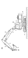
- FIG. 1 is a side view of the excavator 100 according to the present embodiment.
- the excavator 100 includes a lower traveling body 1, an upper swivel body 3 that is swivelably mounted on the lower traveling body 1 via a swivel mechanism 2, a boom 4 as an attachment (working device), and an arm 5. , And a bucket 6 and a cabin 10.
- the lower traveling body 1 includes, for example, a pair of left and right crawlers, and the excavator 100 is driven (self-propelled) by hydraulically driving each crawler with the traveling hydraulic motors 1L and 1R (see FIG. 2).
- the upper swing body 3 turns with respect to the lower traveling body 1 by being driven by the swing hydraulic motor 2A (see FIG. 2).
- the boom 4 is pivotally attached to the center of the front portion of the upper swing body 3 so as to be vertically movable, an arm 5 is pivotally attached to the tip of the boom 4 so as to be vertically rotatable, and a bucket 6 is vertically attached to the tip of the arm 5. It is rotatably pivoted.
- the boom 4, arm 5, and bucket 6 are hydraulically driven by the boom cylinder 7, arm cylinder 8, and bucket cylinder 9 as hydraulic actuators, respectively.
- a hook 80 for hanging work (crane work) using the attachment is attached to the bucket 6 as an end attachment.
- the hook 80 is rotatably connected to a bucket pin whose base end connects between the arm 5 and the bucket 6.
- the hook 80 is stored in the hook storage space formed between the two bucket links when a work other than the hanging work such as excavation work is performed.
- the cabin 10 is a cockpit on which an operator or the like is boarded, and is mounted on the front left side of the upper swivel body 3.
- the excavator 100 operates driven elements such as the lower traveling body 1 (left and right crawlers), the upper turning body 3, the boom 4, the arm 5, and the bucket 6 in response to the operation of the operator boarding the cabin 10.
- the excavator 100 may be configured to be operable by an operator boarding the cabin 10, or may be configured to be remotely controlled (remote operation) from the outside of the excavator 100.
- the inside of the cabin 10 may be unmanned.
- the description will proceed on the premise that the operator's operation includes at least one of the operation of the cabin 10 with respect to the operation device 26 and the remote control of the external operator.
- the remote control includes, for example, a mode in which the shovel 100 is operated by an operation input related to the actuator of the shovel 100 performed by a predetermined external device.
- the excavator 100 transmits, for example, image information (image captured) output by an imaging device that images the surroundings of the upper swivel body 3 to an external device, and the image information is transmitted to a display device provided in the external device (hereinafter, hereinafter, It may be displayed on the "remote control display device"). Further, various information images (information screens) displayed on the display device 50 described later inside the cabin 10 of the excavator 100 may be similarly displayed on the remote control display device of the external device.
- the operator of the external device can remotely control the excavator 100 while checking the display contents such as the captured image and the information screen showing the surrounding state of the excavator 100 displayed on the remote control display device, for example. it can. Then, the excavator 100 operates the actuator in response to the remote control signal indicating the content of the remote control received from the external device, and causes the lower traveling body 1 (left and right crawlers), the upper turning body 3, the boom 4, and the arm. Driven elements such as 5 and the bucket 6 may be driven.
- the remote control may include a mode in which the excavator 100 is operated by, for example, an external voice input or a gesture input to the excavator 100 by a person (for example, a worker) around the excavator 100.
- the excavator 100 is a voice, a worker, or the like spoken by a surrounding worker or the like through a voice input device (for example, a microphone) or a gesture input device (for example, an image pickup device) mounted on the excavator 100. Recognize the gestures performed by. Then, the excavator 100 operates an actuator according to the recognized voice, gesture, or the like, and covers the lower traveling body 1 (left and right crawlers), the upper rotating body 3, the boom 4, the arm 5, the bucket 6, and the like.
- the drive element may be driven.
- the excavator 100 may automatically operate the actuator regardless of the content of the operator's operation.
- the excavator 100 has a function of automatically operating at least a part of driven elements such as the lower traveling body 1 (left and right crawlers), the upper rotating body 3, the boom 4, the arm 5, and the bucket 6 (so-called “automatic”). Realize “driving function” or “machine control function”).
- the automatic operation function is a function (so-called “semi-automatic operation") in which a driven element (hydraulic actuator) other than the driven element (hydraulic actuator) to be operated is automatically operated in response to an operator's operation on the operating device 26 or a remote control. Function ”) may be included. Further, the automatic operation function is a function (so-called “fully automatic operation function") in which at least a part of a plurality of driven elements (hydraulic actuators) is automatically operated on the premise that there is no operation or remote control of the operator's operation device 26. ) May be included. When the fully automatic driving function is enabled in the excavator 100, the inside of the cabin 10 may be unmanned.
- the semi-automatic operation function, the fully automatic operation function, and the like may include a mode in which the operation content of the driven element (hydraulic actuator) to be automatically operated is automatically determined according to a predetermined rule.
- the excavator 100 autonomously makes various judgments, and according to the judgment results, the driven element (hydraulic actuator) to be automatically operated operates autonomously.
- a mode in which the content is determined (so-called "autonomous driving function") may be included.
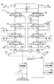
- FIG. 2 is a diagram showing an example of the configuration of the excavator 100 according to the present embodiment.
- the mechanical power line is indicated by a double line
- the high-pressure hydraulic line is indicated by a solid line
- the pilot line is indicated by a broken line
- the electric drive / control line is indicated by a dotted line.
- the hydraulic drive system of the excavator 100 hydraulically drives each of the driven elements such as the lower traveling body 1, the upper swing body 3, the boom 4, the arm 5, and the bucket 6. Including.
- the hydraulic actuator includes a traveling hydraulic motor 1L, 1R, a swing hydraulic motor 2A, a boom cylinder 7, an arm cylinder 8, a bucket cylinder 9, and the like.
- the hydraulic drive system of the excavator 100 according to the present embodiment includes an engine 11, main pumps 14L and 14R, and a control valve 17.
- the engine 11 is the main power source in the hydraulic drive system, and is mounted on the rear part of the upper swing body 3, for example. Specifically, the engine 11 rotates constantly at a preset target rotation speed under the control of the controller 30 to drive the main pumps 14L and 14R and the pilot pump 15.
- the engine 11 is, for example, a diesel engine that uses light oil as fuel.
- the main pumps 14L and 14R are mounted on the rear part of the upper swing body 3 like the engine 11, respectively, and supply hydraulic oil to the control valve 17 through the high-pressure hydraulic line.
- the main pumps 14L and 14R are each driven by the engine 11 as described above.
- the main pumps 14L and 14R are, for example, variable displacement hydraulic pumps, respectively, and the angle (tilt angle) of the swash plate is adjusted by the regulators 13L and 13R under the control of the controller 30, which will be described later, to adjust the angle of the piston.
- the stroke length can be adjusted and the discharge flow rate (discharge pressure) can be controlled.
- the control valve 17 is mounted in the central portion of the upper swing body 3, for example, and is a cover that corresponds to an operation (operation or remote control on the operation device 26) related to a driven element (corresponding hydraulic actuator) by an operator or the like and an automatic operation function. It is a hydraulic control device that controls the hydraulic drive system in response to an operation command related to a drive element (hydraulic actuator). As described above, the control valve 17 is connected to the main pumps 14L and 14R via the high-pressure hydraulic line, and the hydraulic oil supplied from the main pumps 14L and 14R is operated by the operator regarding the driven element (operation of the operating device 26).
- the traveling hydraulic motor 1L for the left crawler
- 1R for the right crawler
- the turning hydraulic pressure are hydraulic actuators. It is selectively supplied to the motor 2A, the boom cylinder 7, the arm cylinder 8, and the bucket cylinder 9.
- the control valve 17 is a control valve 171, 172, 173, 174, 175L, 175R, 176L that controls the flow rate and the flow direction of the hydraulic oil supplied from the main pumps 14L and 14R to the hydraulic actuators, respectively. Includes 176R.
- the hydraulic drive system of the excavator 100 circulates hydraulic oil from the main pumps 14L and 14R driven by the engine 11 to the hydraulic oil tank via the center bypass oil passages C1L and C1R and the parallel oil passages C2L and C2R, respectively.
- the center bypass oil passage C1L starts from the main pump 14L, passes through the control valves 171, 173, 175L, and 176L arranged in the control valve 17 in order, and reaches the hydraulic oil tank.
- the center bypass oil passage C1R starts from the main pump 14R, passes through the control valves 172, 174, 175R, and 176R arranged in the control valve 17 in order, and reaches the hydraulic oil tank.
- the control valve 171 is a spool valve that supplies the hydraulic oil discharged by the main pump 14L to the traveling hydraulic motor 1L and discharges the hydraulic oil discharged by the traveling hydraulic motor 1L to the hydraulic oil tank.
- the control valve 172 is a spool valve that supplies the hydraulic oil discharged by the main pump 14R to the traveling hydraulic motor 1R and discharges the hydraulic oil discharged by the traveling hydraulic motor 1R to the hydraulic oil tank.
- the control valve 173 is a spool valve that supplies the hydraulic oil discharged by the main pump 14L to the swing hydraulic motor 2A and discharges the hydraulic oil discharged by the swing hydraulic motor 2A to the hydraulic oil tank.
- the control valve 174 is a spool valve that supplies the hydraulic oil discharged by the main pump 14R to the bucket cylinder 9 and discharges the hydraulic oil in the bucket cylinder 9 to the hydraulic oil tank.
- the control valves 175L and 175R are spool valves that supply the hydraulic oil discharged by the main pumps 14L and 14R to the boom cylinder 7 and discharge the hydraulic oil in the boom cylinder 7 to the hydraulic oil tank, respectively.
- the control valves 176L and 176R are spool valves that supply the hydraulic oil discharged by the main pumps 14L and 14R to the arm cylinder 8 and discharge the hydraulic oil in the arm cylinder 8 to the hydraulic oil tank.
- the control valves 171, 172, 173, 174, 175L, 175R, 176L, and 176R adjust the flow rate of the hydraulic oil supplied to and discharged from the hydraulic actuator according to the pilot pressure acting on the pilot port, and the flow direction, respectively. To switch.
- the parallel oil passage C2L supplies the hydraulic oil of the main pump 14L to the control valves 171, 173, 175L, and 176L in parallel with the center bypass oil passage C1L.
- the parallel oil passage C2L branches from the center bypass oil passage C1L on the upstream side of the control valve 171 and supplies the hydraulic oil of the main pump 14L in parallel with the control valves 171, 173, 175L, and 176R, respectively. It is configured to be possible.
- the parallel oil passage C2L supplies the hydraulic oil to the control valve further downstream when the flow of the hydraulic oil through the center bypass oil passage C1L is restricted or blocked by any of the control valves 171, 173, and 175L. it can.
- the parallel oil passage C2R supplies the hydraulic oil of the main pump 14R to the control valves 172, 174, 175R and 176R in parallel with the center bypass oil passage C1R.
- the parallel oil passage C2R branches from the center bypass oil passage C1R on the upstream side of the control valve 172, and supplies the hydraulic oil of the main pump 14R in parallel with the control valves 172, 174, 175R, and 176R, respectively. It is configured to be possible.
- the parallel oil passage C2R can supply the hydraulic oil to the control valve further downstream when the flow of the hydraulic oil through the center bypass oil passage C1R is restricted or blocked by any of the control valves 172, 174, and 175R.
- the operating system of the excavator 100 includes a pilot pump 15 and an operating device 26.
- the pilot pump 15 is mounted on the rear part of the upper swing body 3 like the engine 11, and supplies the pilot pressure to the operating device 26 via the pilot line 25, for example.
- the pilot pump 15 is, for example, a fixed-capacity hydraulic pump, and is driven by the engine 11 as described above.
- the operating device 26 is provided near the driver's seat of the cabin 10, for example, so that an operator or the like can operate various driven elements (lower traveling body 1, upper turning body 3, boom 4, arm 5, bucket 6, etc.). It is an operation input means of. In other words, the operating device 26 operates hydraulic actuators (that is, traveling hydraulic motors 1L, 1R, swivel hydraulic motor 2A, boom cylinder 7, arm cylinder 8, bucket cylinder 9, etc.) that drive each driven element. It is an operation input means for performing.
- the operating device 26 includes, for example, four lever devices for operating each of the upper swing body 3, the boom 4, the arm 5, and the bucket 6. Further, the operating device 26 includes, for example, two pedal devices for operating the left crawler and the right crawler (that is, the traveling hydraulic motors 1L and 1R) of the lower traveling body 1.
- the operating device 26 is, for example, a hydraulic pilot type that outputs hydraulic oil having a pilot pressure corresponding to the operation content.
- the lever device, pedal device, and the like included in the operation device 26 are connected to the control valve 17 via the pilot line, respectively, and the hydraulic oil supplied from the pilot pump 25 is used for the operation content.
- the corresponding pilot pressure is output toward the control valve 17.
- a pilot signal (pilot pressure) according to the operating state of the lower traveling body 1, the upper swinging body 3, the boom 4, the arm 5, the bucket 6 and the like in the operating device 26 is input to the control valve 17.
- the pilot pressures on the secondary side of the two pedal devices that operate the left crawler (running hydraulic motor 1L) and the right crawler (running hydraulic motor 1R) are applied to the pilot ports of the control valves 171 and 172, respectively. It works. Further, the pilot pressure on the secondary side of the lever device that operates the upper swing body 3 (swing hydraulic motor 2A) acts on the pilot port of the control valve 173. Further, the pilot pressure on the secondary side of the lever device that operates the boom 4 (boom cylinder 7) acts on the pilot ports of the control valves 175L and 175R. Further, the pilot pressure on the secondary side of the lever device that operates the arm 5 (arm cylinder 8) acts on the pilot ports of the control valves 176L and 176R. Further, the pilot pressure on the secondary side of the lever device that operates the bucket 6 (bucket cylinder 9) acts on the pilot port of the control valve 174. Therefore, the control valve 17 can drive each hydraulic actuator according to the operating state of the operating device 26.
- the operation device 26 may be, for example, an electric type that outputs an electric signal (hereinafter, “operation signal”) corresponding to the operation content.
- operation signal an electric signal
- the operation signal from the operation device 26 is input to the controller 30, and the controller 30 controls each control valve in the control valve 17 according to the input operation signal to operate the operation device 26.
- the control valve in the control valve 17 may be an electromagnetic solenoid type spool valve driven by a command from the controller 30.
- a hydraulic control valve (hereinafter, “operation control valve”) that operates in response to a control command from the controller 30 may be arranged between the pilot pump 15 and the pilot port of each control valve. ..
- the controller 30 controls the operation control valve by a control command corresponding to the operation amount (for example, the lever operation amount) to control the pilot pressure.
- the operation amount for example, the lever operation amount
- each control valve can be operated according to the operation content for the operating device 26.
- the control system of the excavator 100 according to the present embodiment includes the controller 30. Further, the control system of the excavator 100 according to the present embodiment includes regulators 13L and 13R, negative control diaphragms (hereinafter, “negative control diaphragms”) 18L and 18R, negative control pressure sensors 19L and 19R, discharge pressure sensors 28, and the like. It includes an operating pressure sensor 29, a display device 50, and an input device 52.
- negative control diaphragms negative control diaphragms
- the controller 30 (an example of a control device) performs various controls related to the excavator 100.
- the function of the controller 30 may be realized by any hardware, or a combination of any hardware and software.
- the controller 30 includes a processor such as a CPU (Central Processing Unit), a memory device such as a RAM (Random Access Memory), an auxiliary storage device such as a ROM (Read Only Memory), and an interface device for various input / output. It consists mainly of a computer.
- the controller 30 realizes various functions by executing, for example, one or more programs installed in the auxiliary storage device on the CPU.
- the controller 30 sets a target rotation speed based on a work mode (for example, a lifting mode described later) or the like preset by an operation of an operator or the like, and directly or via a dedicated control device of the engine 11. , Drive control is performed to rotate the engine 11 at a constant speed.
- the excavator 100 is defined in advance as a normal mode for performing a normal work such as excavation work and a work mode (hereinafter, "lifting mode") corresponding to a hanging work using an attachment (hook 80). , It may be selectable by an operation of an operator or the like through the input device 52.
- the controller 30 sets the target rotation speed of the engine 11 to be relatively low when the lifting mode is selected. As a result, the operation of the attachment becomes relatively slow in the hanging work. Therefore, the operator can easily perform the hanging operation.
- the controller 30 controls the regulators 13L and 13R, and controls the discharge amount of the main pumps 14L and 14R by adjusting the tilt angle of the swash plate of the main pumps 14L and 14R.
- the controller 30 controls the regulators 13L and 13R according to the discharge pressures of the main pumps 14L and 14R detected by the discharge pressure sensors 28L and 28R, and controls the discharge amounts of the main pumps 14L and 14R. You can. More specifically, the controller 30 may adjust the swash plate tilt angle of the main pump 14L through the regulator 13L in accordance with the increase in the discharge pressure of the main pump 14L to reduce the discharge amount. The same applies to the regulator 13R. As a result, the controller 30 controls the total horsepower of the main pumps 14L and 14R so that the absorbed horsepower of the main pumps 14L and 14R, which is represented by the product of the discharge pressure and the discharge amount, does not exceed the output horsepower of the engine 11. be able to.
- the controller 30 controls the regulators 13L and 13R according to the detection signal corresponding to the control pressure (hereinafter, “negative pump pressure”) generated by the negative control diaphragms 18L and 18R input from the negative control pressure sensors 19L and 19R. Then, the discharge amount of the main pumps 14L and 14R may be controlled. More specifically, the controller 30 reduces the discharge amount of the main pumps 14L and 14R as the negative control pressure increases, and increases the discharge amount of the main pumps 14L and 14R as the negative control pressure decreases.
- negative pump pressure the control pressure generated by the negative control diaphragms 18L and 18R input from the negative control pressure sensors 19L and 19R.
- the hydraulic oil discharged from the main pumps 14L and 14R is sent to the hydraulic actuator to be operated via the control valve corresponding to the hydraulic actuator to be operated. It flows in. Then, the flow of hydraulic oil discharged from the main pumps 14L and 14R reduces or eliminates the amount reaching the negative control diaphragms 18L and 18R, and lowers the negative control pressure generated upstream of the negative control throttles 18L and 18R. As a result, the controller 30 can increase the discharge amount of the main pumps 14L and 14R, circulate sufficient hydraulic oil to the hydraulic actuator to be operated, and reliably drive the hydraulic actuator to be operated.
- the controller 30 wastes the main pumps 14L and 14R, including the pumping loss generated by the hydraulic oil discharged from the main pumps 14L and 14R in the center bypass oil passages C1L and C1R in the standby state of the hydraulic drive system. Energy consumption can be suppressed. Further, when the hydraulic actuator operates, the controller 30 can supply necessary and sufficient hydraulic oil from the main pumps 14L and 14R to the hydraulic actuator to be operated.
- the controller 30 controls the proportional valve for operation as described above, and realizes the operation of the hydraulic actuator according to the operation content of the operating device 26.
- the controller 30 realizes remote control of the excavator 100 by using an operation proportional valve.
- the controller 30 operates a control command corresponding to the content of the remote control specified by the remote control signal received from the external device, the voice input received from the people around the excavator 100, the gesture input, and the like. It may be output to the proportional valve.
- the proportional valve for operation uses the hydraulic oil supplied from the pilot pump 15 to output the pilot pressure corresponding to the control command from the controller 30 and outputs the pilot pressure to the pilot port of the corresponding control valve in the control valve 17. Pilot pressure may be applied.
- the content of the remote control is reflected in the operation of the control valve 17, and the hydraulic actuator realizes the operation of various operating elements (driven elements) according to the content of the remote control.
- the controller 30 realizes the automatic operation function of the excavator 100 by using the proportional valve for operation.
- the controller 30 may output a control command corresponding to the operation command related to the automatic operation function to the operation proportional valve.
- the operation command may be generated by the controller 30 or may be generated by another control device that controls the automatic operation function.
- the proportional valve for operation uses the hydraulic oil supplied from the pilot pump 15 to output the pilot pressure corresponding to the control command from the controller 30 and outputs the pilot pressure to the pilot port of the corresponding control valve in the control valve 17. Pilot pressure may be applied.
- the content of the operation command related to the automatic operation function is reflected in the operation of the control valve 17, and the operation of various operation elements (driven elements) by the automatic operation function is realized by the hydraulic actuator.
- the controller 30 monitors the intrusion of a predetermined object (hereinafter, “monitoring target”) into a predetermined range (hereinafter, “monitoring area”) close to the shovel 100.
- a predetermined object hereinafter, “monitoring target”
- monitoring area a predetermined range
- the monitoring targets include, for example, materials temporarily placed at the work site, fixed non-moving obstacles such as temporary offices at the work site, moving obstacles such as vehicles including trucks, and the like. Obstacles may be included.
- the controller 30 may detect a monitoring target in the monitoring area around the excavator 100 based on the information acquired by the ambient information acquisition device mounted on the excavator 100. Further, when the monitoring target is detected in the monitoring area, the controller 30 may determine (recognize) the position of the monitoring target based on the information acquired by the surrounding information acquisition device.
- the surrounding information acquisition device acquires information representing the surrounding conditions of the excavator 100.
- the surrounding information acquisition device may include, for example, an imaging device that acquires image information around the excavator 100.
- the image pickup apparatus includes, for example, a monocular camera, a stereo camera, a depth camera, a distance image camera, and the like.
- the surrounding information acquisition device includes, for example, a distance sensor capable of acquiring information on the distance between an object around the excavator 100 such as a LIDAR (Light Detection and Raging), a millimeter wave radar, and an ultrasonic sensor. You can.
- the controller 30 may notify the operator of the excavator 100, surrounding workers, and the like to that effect.
- the controller 30 uses a sound output device or the like mounted on the excavator 100 to move inside the cabin 10 or around the excavator 100.
- An audible alarm may be output.
- the sound output device includes, for example, a speaker, a buzzer, and the like.
- the controller 30 when the controller 30 detects a monitoring target in the monitoring area around the excavator 100, the controller 30 uses a display device, a lighting device, or the like mounted on the excavator 100 to direct the inside of the cabin 10 or the periphery of the excavator 100. You may output a visual alarm.
- the excavator 100 can recognize the existence of a monitoring target in a close range around the excavator 100, and can urge workers around the excavator 100 to evacuate from a range close to the excavator 100. Therefore, the safety of the excavator 100 can be improved.
- the operation of the excavator 100 may be restricted regardless of the operation of the operator or the content of the operation command by the automatic operation function. ..
- the limitation of the operation of the excavator 100 includes an embodiment of stopping the operation of the excavator 100.
- the limitation of the operation of the excavator 100 includes a mode in which the operation of the excavator 100 is decelerated from a normal time.
- the controller 30 controls the gate lock valve provided on the pilot line between the pilot pump 15 and the operating device 26, and reduces the pilot pressure supplied to the operating device 26 to reduce the pressure of the excavator 100. The operation may be restricted.
- the controller 30 controls the pressure reducing valve provided in the pilot line between the operating device 26 and the control valve 17, and reduces the pilot pressure acting on the pilot port of the control valve 17, thereby operating the excavator 100. It may be restricted. Further, when the operating device 26 is an electric type, the controller 30 controls the operating proportional valve so that the pilot pressure output from the operating proportional valve becomes smaller than the amount corresponding to the operating signal. The operation of the excavator 100 may be restricted. Thereby, the safety of the excavator 100 can be improved.
- the controller 30 sets the standby flow rate of the main pump 14 to a work other than the suspension work, that is, a case where a normal work (for example, excavation work or the like) is performed. Enlarge.
- the standby flow rate of the main pump 14 is, for example, the flow rate of the main pump 14 in a state of preparing for the start of operation of the hydraulic actuator, such as when the hydraulic actuator is not operated or when the operation is started, and is the lower limit value of the flow rate of the main pump 14.
- the controller 30 makes the standby flow rate of the main pump 14 relatively larger than in the normal mode when the lifting mode is selected through the input device 52. Details of the control method will be described later (see FIG. 3).
- controller 30 may be realized by another controller. That is, the function of the controller 30 may be realized in a manner distributed by a plurality of controllers.
- the regulators 13L and 13R adjust the discharge amount of the main pumps 14L and 14R by adjusting the tilt angle of the swash plate of the main pumps 14L and 14R, respectively, under the control of the controller 30.
- Negative control throttles 18L and 18R are provided between the control valves 176L and 176R, which are the most downstream of the center bypass oil passages C1L and C1R, and the hydraulic oil tank. As a result, the flow of hydraulic oil discharged by the main pumps 14L and 14R is restricted by the negative control throttles 18L and 18R, and the negative control throttles 18L and 18R generate the above-mentioned negative control pressure.
- the negative control pressure sensors 19L and 19R detect the negative control pressure, and the detection signal corresponding to the detected negative control pressure is taken into the controller 30.
- the discharge pressure sensors 28L and 28R detect the discharge pressures of the main pumps 14L and 14R, respectively, and the detection signal corresponding to the detected discharge pressure is taken into the controller 30.
- the operating pressure sensor 29 detects the pilot pressure on the secondary side of the operating device 26, that is, the pilot pressure corresponding to the operating state of each driven element (hydraulic actuator) in the operating device 26.
- the pilot pressure detection signal corresponding to the operating state of the lower traveling body 1, the upper swinging body 3, the boom 4, the arm 5, the bucket 6 and the like in the operating device 26 by the operating pressure sensor 29 is taken into the controller 30.
- the operating pressure sensor 29 is omitted. This is because the controller 30 can grasp the operating state of the operating device 26 from the content of the operating signal output from the operating device 26.
- the display device 50 is provided in a place in the cabin 10 near the driver's seat where an operator or the like can easily see (for example, a pillar portion in the front right part of the cabin 10), and displays various information screens under the control of the controller 30. To do.
- the display device 50 is, for example, a liquid crystal display or an organic EL (Electroluminescence) display, and may be a touch panel type that also serves as an operation unit.
- the input device 52 is provided within reach of a seated operator or the like in the cabin 10, and accepts various operations by the operator or the like.
- the input device 52 includes, for example, an operation input device that receives an operation input from an operator or the like.
- the operation input device includes a touch panel mounted on the display of the display device 50 that displays various information images, a touch pad provided separately from the display of the display device 50, and the tip of the lever portion of the lever device included in the operation device 26. It includes a knob switch provided in the display device 50, a button switch installed around the display device 50, or a button switch, a lever, a toggle and the like arranged at a relatively distant place from the display device 50.
- the input device 52 includes, for example, a voice input device that receives voice input from an operator or the like.
- the voice input device includes, for example, a microphone.
- the input device 52 includes, for example, a gesture input device that accepts gesture input from an operator or the like.
- the gesture input device includes, for example, an imaging device capable of capturing the state of a gesture by an operator or the like in the cabin 10. The signal corresponding to the input content to the input device 52 is taken into the controller 30.
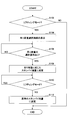
- FIG. 3 is a flowchart schematically showing an example of control processing related to the main pump 14 by the controller 30.
- the processing according to this flowchart is repeatedly executed at predetermined processing cycles, for example, when the lifting mode is not selected, that is, in the normal mode.
- step S102 the controller 30 determines whether or not the excavator 100 is suspending. In this example, the controller 30 determines whether or not the lifting mode is selected. The controller 30 proceeds to step S104 when the lifting mode is selected, and ends the current process when the lifting mode is not selected, that is, in the normal mode.
- the controller 30 may use another method to determine whether or not the excavator 100 is suspending. For example, the controller 30 determines whether or not the suspension operation is performed based on the operation content of the operating device 26 and the measured value of the sensor that detects the pressure of the boom cylinder 7 (hereinafter, “boom cylinder pressure sensor”). You may. Specifically, the measured value of the pressure of the boom cylinder 7 indicates a value capable of determining a state in which a suspended load is suspended to some extent, and the operating device 26 is operated with an operation content assumed to be suspension work. If so, it may be determined that the suspension work is being performed. Further, for example, the controller 30 may recognize the operation and work contents of the attachment based on the image captured by the image pickup device that images the front of the upper swing body 3, and determine whether or not the suspension work is being performed. ..
- step S104 the controller 30 causes the display device 50 to display an operation screen (hereinafter, “suspended load selection screen”) for the operator to select the load of the suspended load from the predetermined weight categories.
- the process proceeds to step S106.
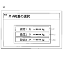
- FIG. 4 is a diagram showing an example of a suspension load selection screen (suspension load selection screen 410) displayed on the display device 50.
- the suspension load selection screen 410 has a relatively large (heavy) weight classification ("setting 1 large”), a medium weight classification (“setting 2 medium”), and a relatively small (light) weight classification ("setting 2 medium”).
- the selection icons 411 to 413 corresponding to each of the setting 3 small ") are displayed. The operator or the like can select the corresponding weight category by selecting and operating any one of the selection icons 411 to 413 through the input device 52.
- step S106 the controller 30 determines whether or not the suspension load selection operation has been performed.
- the controller 30 proceeds to step S108 when the suspension load selection operation is performed through the input device 52 on the suspension load selection screen, and waits until the selection operation is performed when the suspension load selection operation is not performed. ..
- the controller 30 may display an operation screen for inputting a specific numerical value of the suspended load (weight) through the input device 52 instead of the suspended load selection screen. .. Further, the controller 30 may estimate the load (weight) of the suspended load based on the detection information regarding the posture state of the attachment and the measured value of the pressure of the boom cylinder pressure sensor. In this case, the processing of steps S104 and S106 is omitted. Further, in step S106, if the suspension load selection operation is not performed even after a certain period of time has elapsed, the controller 30 automatically considers that the smallest (light) weight category has been selected, and steps S108. You may proceed to.
- step S108 the controller 30 changes the standby flow rate of the main pump 14 according to the weight classification of the suspension load, specifically, the suspension load selected on the suspension load selection screen, and proceeds to step S110.
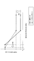
- FIG. 5 is a diagram showing the relationship between the operating amount of the hydraulic actuator (horizontal axis) and the discharge amount of the main pump 14 (vertical axis) in the normal mode and the lifting mode. Specifically, FIG. 5 shows the relationship between the negative control pressure (horizontal axis) in the normal mode and the lifting mode and the discharge amount (vertical axis) per unit time (for example, 1 minute) of the main pump 14. It is a figure which shows.
- the controller 30 increases the standby flow rate as compared with the case of the normal mode (arrow 501 in the figure).
- the discharge pressure of the main pump 14 at the start of operation of the boom cylinder 7 and arm cylinder 8 rises relatively quickly, so that the responsiveness of the attachment at the start of suspension operation can be improved. Therefore, the operator can perform the inching operation in the hanging operation even in the area where the operation amount of the operation device 26 is small.
- the amount of increase in the standby flow rate when the lifting mode is selected may be set so that the larger (heavier) the suspension load is, the larger the increase amount is.
- the controller 30 has a flow rate of the main pump 14 with respect to a change in the operation amount of the suspension operation (that is, the operation amount of at least one of the boom cylinder 7 and the arm cylinder 8).
- the inclination of the portion where the discharge amount per unit time of the main pump 14 increases according to the decrease in the negative controller pressure in the figure) is made smaller than in the normal mode.
- the standby flow rate is increased while keeping the negative control pressure at which the increase in the discharge amount per unit time of the main pump 14 is started is the same as in the case of the normal mode.
- the negative control pressure when the discharge amount per unit time of the main pump 14 reaches the maximum value is reduced (arrow 502 in the figure). Thereby, fine operability in the hanging work can be improved.
- the controller 30 is a standby of one of the main pumps 14L and 14R, which supplies hydraulic oil to the boom cylinder 7 and the arm cylinder 8 for driving the attachment. Only the flow rate may be increased compared to the case of the normal mode. In this case, only the standby flow rate of the main pump 14R, which is different from the main pump 14L that supplies hydraulic oil to the swing hydraulic motor 2A, may be increased. As a result, the standby flow rate of the main pump 14R remains the same as in the normal mode, so that the standby flow rate is tentatively increased and the operation of the upper swivel body 3 in response to the swivel operation is relative to the operator's assumption. It is possible to suppress the situation where the speed becomes faster.
- the controller 30 increases only the standby flow rate of the main pump 14R out of the main pumps 14L and 14R from the normal mode in the situation where the liftin mode is selected, while the traveling operation of the lower traveling body 1 is performed.
- the flow rate of the main pump 14R may be temporarily lowered, that is, returned to the normal mode.
- the lower traveling body 1 is driven by traveling hydraulic motors 1L and 1R having different left and right crawlers, and hydraulic oil is supplied to the traveling hydraulic motors 1L and 1R from the main pumps 14L and 14R, respectively. Therefore, when only the standby flow rate of the main pump 14R is relatively high, the lower traveling body 1 may not be able to travel properly (for example, it may not be able to operate straight ahead properly).
- the controller 30 increases the standby flow rate of both the main pumps 14L and 14R in the situation where the lifting mode is selected, while the controller 30 temporarily lowers the standby flow rate when the turning operation is performed. May be good.
- the upper swivel body 3 swivels faster than expected by the operator or the like in response to the swivel operation. Can be suppressed.
- step S110 the controller 30 determines whether or not the state in which the lifting mode is selected continues.
- the controller 30 proceeds to step S112 when the state in which the lifting mode is selected does not continue, that is, when the lifting mode is deselected and the normal mode is entered.
- step S112 the state in which the lifting mode is selected does not continue, that is, when the lifting mode is deselected and the normal mode is entered.
- step S110 the controller 30 waits until the lifting mode is released, that is, until it returns to the normal mode (step S110 is repeated).
- step S112 the controller 30 returns the standby flow rate to the normal state, that is, reduces the standby flow rate relatively from the lifting mode state, and ends the current process.
- the excavator 100 has a configuration in which various driven elements such as the lower traveling body 1, the upper swivel body 3, the boom 4, the arm 5, and the bucket 6 are all hydraulically driven.
- the unit may be electrically driven. That is, the configuration and the like disclosed in the above-described embodiment may be applied to a hybrid excavator, an electric excavator, and the like.
Landscapes
- Engineering & Computer Science (AREA)
- General Engineering & Computer Science (AREA)
- Mining & Mineral Resources (AREA)
- Civil Engineering (AREA)
- Structural Engineering (AREA)
- Physics & Mathematics (AREA)
- Fluid Mechanics (AREA)
- Mechanical Engineering (AREA)
- Operation Control Of Excavators (AREA)
- Component Parts Of Construction Machinery (AREA)
- Fluid-Pressure Circuits (AREA)
Priority Applications (4)
| Application Number | Priority Date | Filing Date | Title |
|---|---|---|---|
| KR1020217029002A KR102723547B1 (ko) | 2019-03-30 | 2020-03-17 | 쇼벨 |
| EP20783621.4A EP3951100B1 (en) | 2019-03-30 | 2020-03-17 | Shovel |
| CN202080020172.9A CN113544341B (zh) | 2019-03-30 | 2020-03-17 | 挖土机 |
| US17/448,964 US12305366B2 (en) | 2019-03-30 | 2021-09-27 | Shovel |
Applications Claiming Priority (2)
| Application Number | Priority Date | Filing Date | Title |
|---|---|---|---|
| JP2019069474A JP7227830B2 (ja) | 2019-03-30 | 2019-03-30 | ショベル |
| JP2019-069474 | 2019-03-30 |
Related Child Applications (1)
| Application Number | Title | Priority Date | Filing Date |
|---|---|---|---|
| US17/448,964 Continuation US12305366B2 (en) | 2019-03-30 | 2021-09-27 | Shovel |
Publications (1)
| Publication Number | Publication Date |
|---|---|
| WO2020203245A1 true WO2020203245A1 (ja) | 2020-10-08 |
Family
ID=72668288
Family Applications (1)
| Application Number | Title | Priority Date | Filing Date |
|---|---|---|---|
| PCT/JP2020/011622 WO2020203245A1 (ja) | 2019-03-30 | 2020-03-17 | ショベル |
Country Status (6)
Families Citing this family (3)
| Publication number | Priority date | Publication date | Assignee | Title |
|---|---|---|---|---|
| EP4253668B1 (en) * | 2020-11-30 | 2025-03-19 | Sumitomo Heavy Industries, LTD. | Work machine |
| JP2023151653A (ja) * | 2022-03-31 | 2023-10-16 | 住友建機株式会社 | ショベル |
| JP2024094591A (ja) * | 2022-12-28 | 2024-07-10 | 住友重機械工業株式会社 | 作業機械、遠隔操作支援装置 |
Citations (7)
| Publication number | Priority date | Publication date | Assignee | Title |
|---|---|---|---|---|
| JPH0579502A (ja) * | 1991-07-24 | 1993-03-30 | Hitachi Constr Mach Co Ltd | 油圧建設機械 |
| JPH08296603A (ja) * | 1995-04-26 | 1996-11-12 | Hitachi Constr Mach Co Ltd | 油圧建設機械 |
| JP2002129602A (ja) | 2000-10-25 | 2002-05-09 | Shin Caterpillar Mitsubishi Ltd | クレーン機能付建設機械 |
| US20070181361A1 (en) * | 2006-02-08 | 2007-08-09 | Caterpillar Trimble Control Technologies Llc. | System and method for controlling an implement based upon a gear shift |
| JP2018044414A (ja) * | 2016-09-16 | 2018-03-22 | 日立建機株式会社 | 作業機械 |
| JP2018062412A (ja) * | 2016-10-13 | 2018-04-19 | 株式会社神戸製鋼所 | 建設機械 |
| JP2019069474A (ja) | 2019-01-15 | 2019-05-09 | 株式会社Uacj | アルミニウム合金ブレージングシート、その製造方法、アルミニウム合金シート及び熱交換器 |
Family Cites Families (13)
| Publication number | Priority date | Publication date | Assignee | Title |
|---|---|---|---|---|
| WO1992013144A1 (en) | 1991-01-28 | 1992-08-06 | Hitachi Construction Machinery Co., Ltd. | Hydraulic control system in hydraulic construction machine |
| JP3205078B2 (ja) * | 1992-10-02 | 2001-09-04 | 日立建機株式会社 | 油圧建設機械の制御装置 |
| JP3965932B2 (ja) * | 2001-04-19 | 2007-08-29 | 日立建機株式会社 | 油圧ショベルの油圧制御回路 |
| KR100621985B1 (ko) * | 2005-08-02 | 2006-09-11 | 볼보 컨스트럭션 이키프먼트 홀딩 스웨덴 에이비 | 주행시스템 |
| JP2009256058A (ja) | 2008-04-17 | 2009-11-05 | Caterpillar Japan Ltd | クレーン機能付きの油圧ショベル |
| JP5566333B2 (ja) * | 2011-05-11 | 2014-08-06 | 日立建機株式会社 | 建設機械の制御システム |
| JP5985276B2 (ja) * | 2012-07-02 | 2016-09-06 | 住友建機株式会社 | 建設機械の油圧回路及びその制御装置 |
| WO2014123254A1 (ko) * | 2013-02-06 | 2014-08-14 | 볼보 컨스트럭션 이큅먼트 에이비 | 유압식 건설기계 |
| CN105452678A (zh) * | 2013-08-05 | 2016-03-30 | 住友重机械工业株式会社 | 挖土机 |
| JP6226758B2 (ja) * | 2014-01-22 | 2017-11-08 | 住友重機械工業株式会社 | ショベル及び建設機械 |
| KR20170039157A (ko) * | 2014-07-30 | 2017-04-10 | 스미도모쥬기가이고교 가부시키가이샤 | 쇼벨 |
| KR102137157B1 (ko) * | 2017-05-09 | 2020-07-23 | 히다치 겡키 가부시키 가이샤 | 작업 기계 |
| CN109024752B (zh) * | 2018-08-10 | 2021-05-07 | 徐州徐工挖掘机械有限公司 | 挖掘机用行走工况自适应控制系统、控制方法及挖掘机 |
-
2019
- 2019-03-30 JP JP2019069474A patent/JP7227830B2/ja active Active
-
2020
- 2020-03-17 CN CN202080020172.9A patent/CN113544341B/zh active Active
- 2020-03-17 WO PCT/JP2020/011622 patent/WO2020203245A1/ja unknown
- 2020-03-17 KR KR1020217029002A patent/KR102723547B1/ko active Active
- 2020-03-17 EP EP20783621.4A patent/EP3951100B1/en active Active
-
2021
- 2021-09-27 US US17/448,964 patent/US12305366B2/en active Active
Patent Citations (7)
| Publication number | Priority date | Publication date | Assignee | Title |
|---|---|---|---|---|
| JPH0579502A (ja) * | 1991-07-24 | 1993-03-30 | Hitachi Constr Mach Co Ltd | 油圧建設機械 |
| JPH08296603A (ja) * | 1995-04-26 | 1996-11-12 | Hitachi Constr Mach Co Ltd | 油圧建設機械 |
| JP2002129602A (ja) | 2000-10-25 | 2002-05-09 | Shin Caterpillar Mitsubishi Ltd | クレーン機能付建設機械 |
| US20070181361A1 (en) * | 2006-02-08 | 2007-08-09 | Caterpillar Trimble Control Technologies Llc. | System and method for controlling an implement based upon a gear shift |
| JP2018044414A (ja) * | 2016-09-16 | 2018-03-22 | 日立建機株式会社 | 作業機械 |
| JP2018062412A (ja) * | 2016-10-13 | 2018-04-19 | 株式会社神戸製鋼所 | 建設機械 |
| JP2019069474A (ja) | 2019-01-15 | 2019-05-09 | 株式会社Uacj | アルミニウム合金ブレージングシート、その製造方法、アルミニウム合金シート及び熱交換器 |
Non-Patent Citations (1)
| Title |
|---|
| See also references of EP3951100A4 |
Also Published As
| Publication number | Publication date |
|---|---|
| CN113544341B (zh) | 2023-11-17 |
| JP7227830B2 (ja) | 2023-02-22 |
| JP2020165268A (ja) | 2020-10-08 |
| KR102723547B1 (ko) | 2024-10-28 |
| EP3951100A4 (en) | 2022-06-15 |
| US12305366B2 (en) | 2025-05-20 |
| EP3951100A1 (en) | 2022-02-09 |
| KR20210140724A (ko) | 2021-11-23 |
| US20220010530A1 (en) | 2022-01-13 |
| EP3951100B1 (en) | 2023-12-27 |
| CN113544341A (zh) | 2021-10-22 |
Similar Documents
| Publication | Publication Date | Title |
|---|---|---|
| JP7658661B2 (ja) | ショベル及びショベルの管理システム | |
| EP4056766B1 (en) | Construction machine | |
| JP7711862B2 (ja) | ショベル | |
| US20210010239A1 (en) | Work machine and information processing apparatus | |
| US20210262195A1 (en) | Shovel, control device for shovel, and support device for shovel | |
| US12305366B2 (en) | Shovel | |
| JP7683996B2 (ja) | ショベル、ショベルの制御装置 | |
| US11987957B2 (en) | Shovel | |
| JPWO2019189031A1 (ja) | ショベル | |
| WO2020196877A1 (ja) | ショベル及び施工システム | |
| JP7275108B2 (ja) | ショベル | |
| CN113631776B (zh) | 挖土机及施工系统 | |
| WO2021149775A1 (ja) | 作業機械、情報処理装置 | |
| CN113677855A (zh) | 挖土机及挖土机的控制装置 | |
| JP7655504B2 (ja) | ショベル | |
| WO2023190842A1 (ja) | 作業機械 | |
| JP2022146687A (ja) | ショベル | |
| CN113614319B (zh) | 挖土机、信息处理装置 | |
| JP2024094559A (ja) | ショベル | |
| JP2025099533A (ja) | 作業機械の制御装置 | |
| JP2023176796A (ja) | ショベル | |
| WO2024204510A1 (ja) | 作業機械 |
Legal Events
| Date | Code | Title | Description |
|---|---|---|---|
| 121 | Ep: the epo has been informed by wipo that ep was designated in this application |
Ref document number: 20783621 Country of ref document: EP Kind code of ref document: A1 |
|
| NENP | Non-entry into the national phase |
Ref country code: DE |
|
| ENP | Entry into the national phase |
Ref document number: 2020783621 Country of ref document: EP Effective date: 20211102 |