WO2020203245A1 - Shovel - Google Patents
Shovel Download PDFInfo
- Publication number
- WO2020203245A1 WO2020203245A1 PCT/JP2020/011622 JP2020011622W WO2020203245A1 WO 2020203245 A1 WO2020203245 A1 WO 2020203245A1 JP 2020011622 W JP2020011622 W JP 2020011622W WO 2020203245 A1 WO2020203245 A1 WO 2020203245A1
- Authority
- WO
- WIPO (PCT)
- Prior art keywords
- pump
- boom
- excavator
- hydraulic
- controller
- Prior art date
Links
Images
Classifications
-
- E—FIXED CONSTRUCTIONS
- E02—HYDRAULIC ENGINEERING; FOUNDATIONS; SOIL SHIFTING
- E02F—DREDGING; SOIL-SHIFTING
- E02F9/00—Component parts of dredgers or soil-shifting machines, not restricted to one of the kinds covered by groups E02F3/00 - E02F7/00
- E02F9/20—Drives; Control devices
- E02F9/22—Hydraulic or pneumatic drives
- E02F9/2221—Control of flow rate; Load sensing arrangements
- E02F9/2225—Control of flow rate; Load sensing arrangements using pressure-compensating valves
- E02F9/2228—Control of flow rate; Load sensing arrangements using pressure-compensating valves including an electronic controller
-
- E—FIXED CONSTRUCTIONS
- E02—HYDRAULIC ENGINEERING; FOUNDATIONS; SOIL SHIFTING
- E02F—DREDGING; SOIL-SHIFTING
- E02F9/00—Component parts of dredgers or soil-shifting machines, not restricted to one of the kinds covered by groups E02F3/00 - E02F7/00
- E02F9/20—Drives; Control devices
- E02F9/22—Hydraulic or pneumatic drives
- E02F9/2278—Hydraulic circuits
- E02F9/2296—Systems with a variable displacement pump
-
- E—FIXED CONSTRUCTIONS
- E02—HYDRAULIC ENGINEERING; FOUNDATIONS; SOIL SHIFTING
- E02F—DREDGING; SOIL-SHIFTING
- E02F9/00—Component parts of dredgers or soil-shifting machines, not restricted to one of the kinds covered by groups E02F3/00 - E02F7/00
- E02F9/08—Superstructures; Supports for superstructures
- E02F9/10—Supports for movable superstructures mounted on travelling or walking gears or on other superstructures
- E02F9/12—Slewing or traversing gears
- E02F9/121—Turntables, i.e. structure rotatable about 360°
- E02F9/123—Drives or control devices specially adapted therefor
-
- E—FIXED CONSTRUCTIONS
- E02—HYDRAULIC ENGINEERING; FOUNDATIONS; SOIL SHIFTING
- E02F—DREDGING; SOIL-SHIFTING
- E02F9/00—Component parts of dredgers or soil-shifting machines, not restricted to one of the kinds covered by groups E02F3/00 - E02F7/00
- E02F9/20—Drives; Control devices
- E02F9/2025—Particular purposes of control systems not otherwise provided for
- E02F9/205—Remotely operated machines, e.g. unmanned vehicles
-
- E—FIXED CONSTRUCTIONS
- E02—HYDRAULIC ENGINEERING; FOUNDATIONS; SOIL SHIFTING
- E02F—DREDGING; SOIL-SHIFTING
- E02F9/00—Component parts of dredgers or soil-shifting machines, not restricted to one of the kinds covered by groups E02F3/00 - E02F7/00
- E02F9/20—Drives; Control devices
- E02F9/22—Hydraulic or pneumatic drives
- E02F9/2221—Control of flow rate; Load sensing arrangements
- E02F9/2232—Control of flow rate; Load sensing arrangements using one or more variable displacement pumps
- E02F9/2235—Control of flow rate; Load sensing arrangements using one or more variable displacement pumps including an electronic controller
-
- E—FIXED CONSTRUCTIONS
- E02—HYDRAULIC ENGINEERING; FOUNDATIONS; SOIL SHIFTING
- E02F—DREDGING; SOIL-SHIFTING
- E02F9/00—Component parts of dredgers or soil-shifting machines, not restricted to one of the kinds covered by groups E02F3/00 - E02F7/00
- E02F9/20—Drives; Control devices
- E02F9/22—Hydraulic or pneumatic drives
- E02F9/2221—Control of flow rate; Load sensing arrangements
- E02F9/2239—Control of flow rate; Load sensing arrangements using two or more pumps with cross-assistance
- E02F9/2242—Control of flow rate; Load sensing arrangements using two or more pumps with cross-assistance including an electronic controller
-
- E—FIXED CONSTRUCTIONS
- E02—HYDRAULIC ENGINEERING; FOUNDATIONS; SOIL SHIFTING
- E02F—DREDGING; SOIL-SHIFTING
- E02F9/00—Component parts of dredgers or soil-shifting machines, not restricted to one of the kinds covered by groups E02F3/00 - E02F7/00
- E02F9/20—Drives; Control devices
- E02F9/22—Hydraulic or pneumatic drives
- E02F9/2278—Hydraulic circuits
- E02F9/2282—Systems using center bypass type changeover valves
-
- E—FIXED CONSTRUCTIONS
- E02—HYDRAULIC ENGINEERING; FOUNDATIONS; SOIL SHIFTING
- E02F—DREDGING; SOIL-SHIFTING
- E02F9/00—Component parts of dredgers or soil-shifting machines, not restricted to one of the kinds covered by groups E02F3/00 - E02F7/00
- E02F9/26—Indicating devices
-
- E—FIXED CONSTRUCTIONS
- E02—HYDRAULIC ENGINEERING; FOUNDATIONS; SOIL SHIFTING
- E02F—DREDGING; SOIL-SHIFTING
- E02F9/00—Component parts of dredgers or soil-shifting machines, not restricted to one of the kinds covered by groups E02F3/00 - E02F7/00
- E02F9/26—Indicating devices
- E02F9/261—Surveying the work-site to be treated
- E02F9/262—Surveying the work-site to be treated with follow-up actions to control the work tool, e.g. controller
-
- F—MECHANICAL ENGINEERING; LIGHTING; HEATING; WEAPONS; BLASTING
- F15—FLUID-PRESSURE ACTUATORS; HYDRAULICS OR PNEUMATICS IN GENERAL
- F15B—SYSTEMS ACTING BY MEANS OF FLUIDS IN GENERAL; FLUID-PRESSURE ACTUATORS, e.g. SERVOMOTORS; DETAILS OF FLUID-PRESSURE SYSTEMS, NOT OTHERWISE PROVIDED FOR
- F15B11/00—Servomotor systems without provision for follow-up action; Circuits therefor
- F15B11/02—Systems essentially incorporating special features for controlling the speed or actuating force of an output member
-
- F—MECHANICAL ENGINEERING; LIGHTING; HEATING; WEAPONS; BLASTING
- F15—FLUID-PRESSURE ACTUATORS; HYDRAULICS OR PNEUMATICS IN GENERAL
- F15B—SYSTEMS ACTING BY MEANS OF FLUIDS IN GENERAL; FLUID-PRESSURE ACTUATORS, e.g. SERVOMOTORS; DETAILS OF FLUID-PRESSURE SYSTEMS, NOT OTHERWISE PROVIDED FOR
- F15B11/00—Servomotor systems without provision for follow-up action; Circuits therefor
- F15B11/16—Servomotor systems without provision for follow-up action; Circuits therefor with two or more servomotors
- F15B11/17—Servomotor systems without provision for follow-up action; Circuits therefor with two or more servomotors using two or more pumps
Definitions
- This disclosure relates to excavators.
- Patent Document 1 a technique for improving the turning operability of the upper swinging body during suspension work (also referred to as crane work) using an excavator attachment is known (for example, Patent Document 1).
- an upper swing body that is freely mounted on the lower running body and An attachment including a boom attached to the upper swing body and an arm attached to the tip of the boom, and The boom cylinder that drives the boom and An arm cylinder that drives the arm and A hydraulic pump that supplies hydraulic oil to the boom cylinder and the arm cylinder
- a control device for controlling the hydraulic pump is provided.
- the control device increases the standby flow rate of the hydraulic pump as compared with the case where other work other than the suspension work is performed.
- a shovel is provided.
- a control device for controlling the hydraulic pump is provided.
- the control device is described according to at least one of the magnitude of the suspension load, the load state of the boom cylinder, the predetermined working mode of the excavator, the operating state of the lower traveling body, and the turning state of the upper swing body. Change the standby flow rate of the hydraulic pump, A shovel is provided.
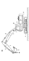
- FIG. 1 is a side view of the excavator 100 according to the present embodiment.
- the excavator 100 includes a lower traveling body 1, an upper swivel body 3 that is swivelably mounted on the lower traveling body 1 via a swivel mechanism 2, a boom 4 as an attachment (working device), and an arm 5. , And a bucket 6 and a cabin 10.
- the lower traveling body 1 includes, for example, a pair of left and right crawlers, and the excavator 100 is driven (self-propelled) by hydraulically driving each crawler with the traveling hydraulic motors 1L and 1R (see FIG. 2).
- the upper swing body 3 turns with respect to the lower traveling body 1 by being driven by the swing hydraulic motor 2A (see FIG. 2).
- the boom 4 is pivotally attached to the center of the front portion of the upper swing body 3 so as to be vertically movable, an arm 5 is pivotally attached to the tip of the boom 4 so as to be vertically rotatable, and a bucket 6 is vertically attached to the tip of the arm 5. It is rotatably pivoted.
- the boom 4, arm 5, and bucket 6 are hydraulically driven by the boom cylinder 7, arm cylinder 8, and bucket cylinder 9 as hydraulic actuators, respectively.
- a hook 80 for hanging work (crane work) using the attachment is attached to the bucket 6 as an end attachment.
- the hook 80 is rotatably connected to a bucket pin whose base end connects between the arm 5 and the bucket 6.
- the hook 80 is stored in the hook storage space formed between the two bucket links when a work other than the hanging work such as excavation work is performed.
- the cabin 10 is a cockpit on which an operator or the like is boarded, and is mounted on the front left side of the upper swivel body 3.
- the excavator 100 operates driven elements such as the lower traveling body 1 (left and right crawlers), the upper turning body 3, the boom 4, the arm 5, and the bucket 6 in response to the operation of the operator boarding the cabin 10.
- the excavator 100 may be configured to be operable by an operator boarding the cabin 10, or may be configured to be remotely controlled (remote operation) from the outside of the excavator 100.
- the inside of the cabin 10 may be unmanned.
- the description will proceed on the premise that the operator's operation includes at least one of the operation of the cabin 10 with respect to the operation device 26 and the remote control of the external operator.
- the remote control includes, for example, a mode in which the shovel 100 is operated by an operation input related to the actuator of the shovel 100 performed by a predetermined external device.
- the excavator 100 transmits, for example, image information (image captured) output by an imaging device that images the surroundings of the upper swivel body 3 to an external device, and the image information is transmitted to a display device provided in the external device (hereinafter, hereinafter, It may be displayed on the "remote control display device"). Further, various information images (information screens) displayed on the display device 50 described later inside the cabin 10 of the excavator 100 may be similarly displayed on the remote control display device of the external device.
- the operator of the external device can remotely control the excavator 100 while checking the display contents such as the captured image and the information screen showing the surrounding state of the excavator 100 displayed on the remote control display device, for example. it can. Then, the excavator 100 operates the actuator in response to the remote control signal indicating the content of the remote control received from the external device, and causes the lower traveling body 1 (left and right crawlers), the upper turning body 3, the boom 4, and the arm. Driven elements such as 5 and the bucket 6 may be driven.
- the remote control may include a mode in which the excavator 100 is operated by, for example, an external voice input or a gesture input to the excavator 100 by a person (for example, a worker) around the excavator 100.
- the excavator 100 is a voice, a worker, or the like spoken by a surrounding worker or the like through a voice input device (for example, a microphone) or a gesture input device (for example, an image pickup device) mounted on the excavator 100. Recognize the gestures performed by. Then, the excavator 100 operates an actuator according to the recognized voice, gesture, or the like, and covers the lower traveling body 1 (left and right crawlers), the upper rotating body 3, the boom 4, the arm 5, the bucket 6, and the like.
- the drive element may be driven.
- the excavator 100 may automatically operate the actuator regardless of the content of the operator's operation.
- the excavator 100 has a function of automatically operating at least a part of driven elements such as the lower traveling body 1 (left and right crawlers), the upper rotating body 3, the boom 4, the arm 5, and the bucket 6 (so-called “automatic”). Realize “driving function” or “machine control function”).
- the automatic operation function is a function (so-called “semi-automatic operation") in which a driven element (hydraulic actuator) other than the driven element (hydraulic actuator) to be operated is automatically operated in response to an operator's operation on the operating device 26 or a remote control. Function ”) may be included. Further, the automatic operation function is a function (so-called “fully automatic operation function") in which at least a part of a plurality of driven elements (hydraulic actuators) is automatically operated on the premise that there is no operation or remote control of the operator's operation device 26. ) May be included. When the fully automatic driving function is enabled in the excavator 100, the inside of the cabin 10 may be unmanned.
- the semi-automatic operation function, the fully automatic operation function, and the like may include a mode in which the operation content of the driven element (hydraulic actuator) to be automatically operated is automatically determined according to a predetermined rule.
- the excavator 100 autonomously makes various judgments, and according to the judgment results, the driven element (hydraulic actuator) to be automatically operated operates autonomously.
- a mode in which the content is determined (so-called "autonomous driving function") may be included.
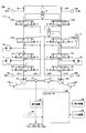
- FIG. 2 is a diagram showing an example of the configuration of the excavator 100 according to the present embodiment.
- the mechanical power line is indicated by a double line
- the high-pressure hydraulic line is indicated by a solid line
- the pilot line is indicated by a broken line
- the electric drive / control line is indicated by a dotted line.
- the hydraulic drive system of the excavator 100 hydraulically drives each of the driven elements such as the lower traveling body 1, the upper swing body 3, the boom 4, the arm 5, and the bucket 6. Including.
- the hydraulic actuator includes a traveling hydraulic motor 1L, 1R, a swing hydraulic motor 2A, a boom cylinder 7, an arm cylinder 8, a bucket cylinder 9, and the like.
- the hydraulic drive system of the excavator 100 according to the present embodiment includes an engine 11, main pumps 14L and 14R, and a control valve 17.
- the engine 11 is the main power source in the hydraulic drive system, and is mounted on the rear part of the upper swing body 3, for example. Specifically, the engine 11 rotates constantly at a preset target rotation speed under the control of the controller 30 to drive the main pumps 14L and 14R and the pilot pump 15.
- the engine 11 is, for example, a diesel engine that uses light oil as fuel.
- the main pumps 14L and 14R are mounted on the rear part of the upper swing body 3 like the engine 11, respectively, and supply hydraulic oil to the control valve 17 through the high-pressure hydraulic line.
- the main pumps 14L and 14R are each driven by the engine 11 as described above.
- the main pumps 14L and 14R are, for example, variable displacement hydraulic pumps, respectively, and the angle (tilt angle) of the swash plate is adjusted by the regulators 13L and 13R under the control of the controller 30, which will be described later, to adjust the angle of the piston.
- the stroke length can be adjusted and the discharge flow rate (discharge pressure) can be controlled.
- the control valve 17 is mounted in the central portion of the upper swing body 3, for example, and is a cover that corresponds to an operation (operation or remote control on the operation device 26) related to a driven element (corresponding hydraulic actuator) by an operator or the like and an automatic operation function. It is a hydraulic control device that controls the hydraulic drive system in response to an operation command related to a drive element (hydraulic actuator). As described above, the control valve 17 is connected to the main pumps 14L and 14R via the high-pressure hydraulic line, and the hydraulic oil supplied from the main pumps 14L and 14R is operated by the operator regarding the driven element (operation of the operating device 26).
- the traveling hydraulic motor 1L for the left crawler
- 1R for the right crawler
- the turning hydraulic pressure are hydraulic actuators. It is selectively supplied to the motor 2A, the boom cylinder 7, the arm cylinder 8, and the bucket cylinder 9.
- the control valve 17 is a control valve 171, 172, 173, 174, 175L, 175R, 176L that controls the flow rate and the flow direction of the hydraulic oil supplied from the main pumps 14L and 14R to the hydraulic actuators, respectively. Includes 176R.
- the hydraulic drive system of the excavator 100 circulates hydraulic oil from the main pumps 14L and 14R driven by the engine 11 to the hydraulic oil tank via the center bypass oil passages C1L and C1R and the parallel oil passages C2L and C2R, respectively.
- the center bypass oil passage C1L starts from the main pump 14L, passes through the control valves 171, 173, 175L, and 176L arranged in the control valve 17 in order, and reaches the hydraulic oil tank.
- the center bypass oil passage C1R starts from the main pump 14R, passes through the control valves 172, 174, 175R, and 176R arranged in the control valve 17 in order, and reaches the hydraulic oil tank.
- the control valve 171 is a spool valve that supplies the hydraulic oil discharged by the main pump 14L to the traveling hydraulic motor 1L and discharges the hydraulic oil discharged by the traveling hydraulic motor 1L to the hydraulic oil tank.
- the control valve 172 is a spool valve that supplies the hydraulic oil discharged by the main pump 14R to the traveling hydraulic motor 1R and discharges the hydraulic oil discharged by the traveling hydraulic motor 1R to the hydraulic oil tank.
- the control valve 173 is a spool valve that supplies the hydraulic oil discharged by the main pump 14L to the swing hydraulic motor 2A and discharges the hydraulic oil discharged by the swing hydraulic motor 2A to the hydraulic oil tank.
- the control valve 174 is a spool valve that supplies the hydraulic oil discharged by the main pump 14R to the bucket cylinder 9 and discharges the hydraulic oil in the bucket cylinder 9 to the hydraulic oil tank.
- the control valves 175L and 175R are spool valves that supply the hydraulic oil discharged by the main pumps 14L and 14R to the boom cylinder 7 and discharge the hydraulic oil in the boom cylinder 7 to the hydraulic oil tank, respectively.
- the control valves 176L and 176R are spool valves that supply the hydraulic oil discharged by the main pumps 14L and 14R to the arm cylinder 8 and discharge the hydraulic oil in the arm cylinder 8 to the hydraulic oil tank.
- the control valves 171, 172, 173, 174, 175L, 175R, 176L, and 176R adjust the flow rate of the hydraulic oil supplied to and discharged from the hydraulic actuator according to the pilot pressure acting on the pilot port, and the flow direction, respectively. To switch.
- the parallel oil passage C2L supplies the hydraulic oil of the main pump 14L to the control valves 171, 173, 175L, and 176L in parallel with the center bypass oil passage C1L.
- the parallel oil passage C2L branches from the center bypass oil passage C1L on the upstream side of the control valve 171 and supplies the hydraulic oil of the main pump 14L in parallel with the control valves 171, 173, 175L, and 176R, respectively. It is configured to be possible.
- the parallel oil passage C2L supplies the hydraulic oil to the control valve further downstream when the flow of the hydraulic oil through the center bypass oil passage C1L is restricted or blocked by any of the control valves 171, 173, and 175L. it can.
- the parallel oil passage C2R supplies the hydraulic oil of the main pump 14R to the control valves 172, 174, 175R and 176R in parallel with the center bypass oil passage C1R.
- the parallel oil passage C2R branches from the center bypass oil passage C1R on the upstream side of the control valve 172, and supplies the hydraulic oil of the main pump 14R in parallel with the control valves 172, 174, 175R, and 176R, respectively. It is configured to be possible.
- the parallel oil passage C2R can supply the hydraulic oil to the control valve further downstream when the flow of the hydraulic oil through the center bypass oil passage C1R is restricted or blocked by any of the control valves 172, 174, and 175R.
- the operating system of the excavator 100 includes a pilot pump 15 and an operating device 26.
- the pilot pump 15 is mounted on the rear part of the upper swing body 3 like the engine 11, and supplies the pilot pressure to the operating device 26 via the pilot line 25, for example.
- the pilot pump 15 is, for example, a fixed-capacity hydraulic pump, and is driven by the engine 11 as described above.
- the operating device 26 is provided near the driver's seat of the cabin 10, for example, so that an operator or the like can operate various driven elements (lower traveling body 1, upper turning body 3, boom 4, arm 5, bucket 6, etc.). It is an operation input means of. In other words, the operating device 26 operates hydraulic actuators (that is, traveling hydraulic motors 1L, 1R, swivel hydraulic motor 2A, boom cylinder 7, arm cylinder 8, bucket cylinder 9, etc.) that drive each driven element. It is an operation input means for performing.
- the operating device 26 includes, for example, four lever devices for operating each of the upper swing body 3, the boom 4, the arm 5, and the bucket 6. Further, the operating device 26 includes, for example, two pedal devices for operating the left crawler and the right crawler (that is, the traveling hydraulic motors 1L and 1R) of the lower traveling body 1.
- the operating device 26 is, for example, a hydraulic pilot type that outputs hydraulic oil having a pilot pressure corresponding to the operation content.
- the lever device, pedal device, and the like included in the operation device 26 are connected to the control valve 17 via the pilot line, respectively, and the hydraulic oil supplied from the pilot pump 25 is used for the operation content.
- the corresponding pilot pressure is output toward the control valve 17.
- a pilot signal (pilot pressure) according to the operating state of the lower traveling body 1, the upper swinging body 3, the boom 4, the arm 5, the bucket 6 and the like in the operating device 26 is input to the control valve 17.
- the pilot pressures on the secondary side of the two pedal devices that operate the left crawler (running hydraulic motor 1L) and the right crawler (running hydraulic motor 1R) are applied to the pilot ports of the control valves 171 and 172, respectively. It works. Further, the pilot pressure on the secondary side of the lever device that operates the upper swing body 3 (swing hydraulic motor 2A) acts on the pilot port of the control valve 173. Further, the pilot pressure on the secondary side of the lever device that operates the boom 4 (boom cylinder 7) acts on the pilot ports of the control valves 175L and 175R. Further, the pilot pressure on the secondary side of the lever device that operates the arm 5 (arm cylinder 8) acts on the pilot ports of the control valves 176L and 176R. Further, the pilot pressure on the secondary side of the lever device that operates the bucket 6 (bucket cylinder 9) acts on the pilot port of the control valve 174. Therefore, the control valve 17 can drive each hydraulic actuator according to the operating state of the operating device 26.
- the operation device 26 may be, for example, an electric type that outputs an electric signal (hereinafter, “operation signal”) corresponding to the operation content.
- operation signal an electric signal
- the operation signal from the operation device 26 is input to the controller 30, and the controller 30 controls each control valve in the control valve 17 according to the input operation signal to operate the operation device 26.
- the control valve in the control valve 17 may be an electromagnetic solenoid type spool valve driven by a command from the controller 30.
- a hydraulic control valve (hereinafter, “operation control valve”) that operates in response to a control command from the controller 30 may be arranged between the pilot pump 15 and the pilot port of each control valve. ..
- the controller 30 controls the operation control valve by a control command corresponding to the operation amount (for example, the lever operation amount) to control the pilot pressure.
- the operation amount for example, the lever operation amount
- each control valve can be operated according to the operation content for the operating device 26.
- the control system of the excavator 100 according to the present embodiment includes the controller 30. Further, the control system of the excavator 100 according to the present embodiment includes regulators 13L and 13R, negative control diaphragms (hereinafter, “negative control diaphragms”) 18L and 18R, negative control pressure sensors 19L and 19R, discharge pressure sensors 28, and the like. It includes an operating pressure sensor 29, a display device 50, and an input device 52.
- negative control diaphragms negative control diaphragms
- the controller 30 (an example of a control device) performs various controls related to the excavator 100.
- the function of the controller 30 may be realized by any hardware, or a combination of any hardware and software.
- the controller 30 includes a processor such as a CPU (Central Processing Unit), a memory device such as a RAM (Random Access Memory), an auxiliary storage device such as a ROM (Read Only Memory), and an interface device for various input / output. It consists mainly of a computer.
- the controller 30 realizes various functions by executing, for example, one or more programs installed in the auxiliary storage device on the CPU.
- the controller 30 sets a target rotation speed based on a work mode (for example, a lifting mode described later) or the like preset by an operation of an operator or the like, and directly or via a dedicated control device of the engine 11. , Drive control is performed to rotate the engine 11 at a constant speed.
- the excavator 100 is defined in advance as a normal mode for performing a normal work such as excavation work and a work mode (hereinafter, "lifting mode") corresponding to a hanging work using an attachment (hook 80). , It may be selectable by an operation of an operator or the like through the input device 52.
- the controller 30 sets the target rotation speed of the engine 11 to be relatively low when the lifting mode is selected. As a result, the operation of the attachment becomes relatively slow in the hanging work. Therefore, the operator can easily perform the hanging operation.
- the controller 30 controls the regulators 13L and 13R, and controls the discharge amount of the main pumps 14L and 14R by adjusting the tilt angle of the swash plate of the main pumps 14L and 14R.
- the controller 30 controls the regulators 13L and 13R according to the discharge pressures of the main pumps 14L and 14R detected by the discharge pressure sensors 28L and 28R, and controls the discharge amounts of the main pumps 14L and 14R. You can. More specifically, the controller 30 may adjust the swash plate tilt angle of the main pump 14L through the regulator 13L in accordance with the increase in the discharge pressure of the main pump 14L to reduce the discharge amount. The same applies to the regulator 13R. As a result, the controller 30 controls the total horsepower of the main pumps 14L and 14R so that the absorbed horsepower of the main pumps 14L and 14R, which is represented by the product of the discharge pressure and the discharge amount, does not exceed the output horsepower of the engine 11. be able to.
- the controller 30 controls the regulators 13L and 13R according to the detection signal corresponding to the control pressure (hereinafter, “negative pump pressure”) generated by the negative control diaphragms 18L and 18R input from the negative control pressure sensors 19L and 19R. Then, the discharge amount of the main pumps 14L and 14R may be controlled. More specifically, the controller 30 reduces the discharge amount of the main pumps 14L and 14R as the negative control pressure increases, and increases the discharge amount of the main pumps 14L and 14R as the negative control pressure decreases.
- negative pump pressure the control pressure generated by the negative control diaphragms 18L and 18R input from the negative control pressure sensors 19L and 19R.
- the hydraulic oil discharged from the main pumps 14L and 14R is sent to the hydraulic actuator to be operated via the control valve corresponding to the hydraulic actuator to be operated. It flows in. Then, the flow of hydraulic oil discharged from the main pumps 14L and 14R reduces or eliminates the amount reaching the negative control diaphragms 18L and 18R, and lowers the negative control pressure generated upstream of the negative control throttles 18L and 18R. As a result, the controller 30 can increase the discharge amount of the main pumps 14L and 14R, circulate sufficient hydraulic oil to the hydraulic actuator to be operated, and reliably drive the hydraulic actuator to be operated.
- the controller 30 wastes the main pumps 14L and 14R, including the pumping loss generated by the hydraulic oil discharged from the main pumps 14L and 14R in the center bypass oil passages C1L and C1R in the standby state of the hydraulic drive system. Energy consumption can be suppressed. Further, when the hydraulic actuator operates, the controller 30 can supply necessary and sufficient hydraulic oil from the main pumps 14L and 14R to the hydraulic actuator to be operated.
- the controller 30 controls the proportional valve for operation as described above, and realizes the operation of the hydraulic actuator according to the operation content of the operating device 26.
- the controller 30 realizes remote control of the excavator 100 by using an operation proportional valve.
- the controller 30 operates a control command corresponding to the content of the remote control specified by the remote control signal received from the external device, the voice input received from the people around the excavator 100, the gesture input, and the like. It may be output to the proportional valve.
- the proportional valve for operation uses the hydraulic oil supplied from the pilot pump 15 to output the pilot pressure corresponding to the control command from the controller 30 and outputs the pilot pressure to the pilot port of the corresponding control valve in the control valve 17. Pilot pressure may be applied.
- the content of the remote control is reflected in the operation of the control valve 17, and the hydraulic actuator realizes the operation of various operating elements (driven elements) according to the content of the remote control.
- the controller 30 realizes the automatic operation function of the excavator 100 by using the proportional valve for operation.
- the controller 30 may output a control command corresponding to the operation command related to the automatic operation function to the operation proportional valve.
- the operation command may be generated by the controller 30 or may be generated by another control device that controls the automatic operation function.
- the proportional valve for operation uses the hydraulic oil supplied from the pilot pump 15 to output the pilot pressure corresponding to the control command from the controller 30 and outputs the pilot pressure to the pilot port of the corresponding control valve in the control valve 17. Pilot pressure may be applied.
- the content of the operation command related to the automatic operation function is reflected in the operation of the control valve 17, and the operation of various operation elements (driven elements) by the automatic operation function is realized by the hydraulic actuator.
- the controller 30 monitors the intrusion of a predetermined object (hereinafter, “monitoring target”) into a predetermined range (hereinafter, “monitoring area”) close to the shovel 100.
- a predetermined object hereinafter, “monitoring target”
- monitoring area a predetermined range
- the monitoring targets include, for example, materials temporarily placed at the work site, fixed non-moving obstacles such as temporary offices at the work site, moving obstacles such as vehicles including trucks, and the like. Obstacles may be included.
- the controller 30 may detect a monitoring target in the monitoring area around the excavator 100 based on the information acquired by the ambient information acquisition device mounted on the excavator 100. Further, when the monitoring target is detected in the monitoring area, the controller 30 may determine (recognize) the position of the monitoring target based on the information acquired by the surrounding information acquisition device.
- the surrounding information acquisition device acquires information representing the surrounding conditions of the excavator 100.
- the surrounding information acquisition device may include, for example, an imaging device that acquires image information around the excavator 100.
- the image pickup apparatus includes, for example, a monocular camera, a stereo camera, a depth camera, a distance image camera, and the like.
- the surrounding information acquisition device includes, for example, a distance sensor capable of acquiring information on the distance between an object around the excavator 100 such as a LIDAR (Light Detection and Raging), a millimeter wave radar, and an ultrasonic sensor. You can.
- the controller 30 may notify the operator of the excavator 100, surrounding workers, and the like to that effect.
- the controller 30 uses a sound output device or the like mounted on the excavator 100 to move inside the cabin 10 or around the excavator 100.
- An audible alarm may be output.
- the sound output device includes, for example, a speaker, a buzzer, and the like.
- the controller 30 when the controller 30 detects a monitoring target in the monitoring area around the excavator 100, the controller 30 uses a display device, a lighting device, or the like mounted on the excavator 100 to direct the inside of the cabin 10 or the periphery of the excavator 100. You may output a visual alarm.
- the excavator 100 can recognize the existence of a monitoring target in a close range around the excavator 100, and can urge workers around the excavator 100 to evacuate from a range close to the excavator 100. Therefore, the safety of the excavator 100 can be improved.
- the operation of the excavator 100 may be restricted regardless of the operation of the operator or the content of the operation command by the automatic operation function. ..
- the limitation of the operation of the excavator 100 includes an embodiment of stopping the operation of the excavator 100.
- the limitation of the operation of the excavator 100 includes a mode in which the operation of the excavator 100 is decelerated from a normal time.
- the controller 30 controls the gate lock valve provided on the pilot line between the pilot pump 15 and the operating device 26, and reduces the pilot pressure supplied to the operating device 26 to reduce the pressure of the excavator 100. The operation may be restricted.
- the controller 30 controls the pressure reducing valve provided in the pilot line between the operating device 26 and the control valve 17, and reduces the pilot pressure acting on the pilot port of the control valve 17, thereby operating the excavator 100. It may be restricted. Further, when the operating device 26 is an electric type, the controller 30 controls the operating proportional valve so that the pilot pressure output from the operating proportional valve becomes smaller than the amount corresponding to the operating signal. The operation of the excavator 100 may be restricted. Thereby, the safety of the excavator 100 can be improved.
- the controller 30 sets the standby flow rate of the main pump 14 to a work other than the suspension work, that is, a case where a normal work (for example, excavation work or the like) is performed. Enlarge.
- the standby flow rate of the main pump 14 is, for example, the flow rate of the main pump 14 in a state of preparing for the start of operation of the hydraulic actuator, such as when the hydraulic actuator is not operated or when the operation is started, and is the lower limit value of the flow rate of the main pump 14.
- the controller 30 makes the standby flow rate of the main pump 14 relatively larger than in the normal mode when the lifting mode is selected through the input device 52. Details of the control method will be described later (see FIG. 3).
- controller 30 may be realized by another controller. That is, the function of the controller 30 may be realized in a manner distributed by a plurality of controllers.
- the regulators 13L and 13R adjust the discharge amount of the main pumps 14L and 14R by adjusting the tilt angle of the swash plate of the main pumps 14L and 14R, respectively, under the control of the controller 30.
- Negative control throttles 18L and 18R are provided between the control valves 176L and 176R, which are the most downstream of the center bypass oil passages C1L and C1R, and the hydraulic oil tank. As a result, the flow of hydraulic oil discharged by the main pumps 14L and 14R is restricted by the negative control throttles 18L and 18R, and the negative control throttles 18L and 18R generate the above-mentioned negative control pressure.
- the negative control pressure sensors 19L and 19R detect the negative control pressure, and the detection signal corresponding to the detected negative control pressure is taken into the controller 30.
- the discharge pressure sensors 28L and 28R detect the discharge pressures of the main pumps 14L and 14R, respectively, and the detection signal corresponding to the detected discharge pressure is taken into the controller 30.
- the operating pressure sensor 29 detects the pilot pressure on the secondary side of the operating device 26, that is, the pilot pressure corresponding to the operating state of each driven element (hydraulic actuator) in the operating device 26.
- the pilot pressure detection signal corresponding to the operating state of the lower traveling body 1, the upper swinging body 3, the boom 4, the arm 5, the bucket 6 and the like in the operating device 26 by the operating pressure sensor 29 is taken into the controller 30.
- the operating pressure sensor 29 is omitted. This is because the controller 30 can grasp the operating state of the operating device 26 from the content of the operating signal output from the operating device 26.
- the display device 50 is provided in a place in the cabin 10 near the driver's seat where an operator or the like can easily see (for example, a pillar portion in the front right part of the cabin 10), and displays various information screens under the control of the controller 30. To do.
- the display device 50 is, for example, a liquid crystal display or an organic EL (Electroluminescence) display, and may be a touch panel type that also serves as an operation unit.
- the input device 52 is provided within reach of a seated operator or the like in the cabin 10, and accepts various operations by the operator or the like.
- the input device 52 includes, for example, an operation input device that receives an operation input from an operator or the like.
- the operation input device includes a touch panel mounted on the display of the display device 50 that displays various information images, a touch pad provided separately from the display of the display device 50, and the tip of the lever portion of the lever device included in the operation device 26. It includes a knob switch provided in the display device 50, a button switch installed around the display device 50, or a button switch, a lever, a toggle and the like arranged at a relatively distant place from the display device 50.
- the input device 52 includes, for example, a voice input device that receives voice input from an operator or the like.
- the voice input device includes, for example, a microphone.
- the input device 52 includes, for example, a gesture input device that accepts gesture input from an operator or the like.
- the gesture input device includes, for example, an imaging device capable of capturing the state of a gesture by an operator or the like in the cabin 10. The signal corresponding to the input content to the input device 52 is taken into the controller 30.
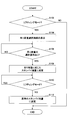
- FIG. 3 is a flowchart schematically showing an example of control processing related to the main pump 14 by the controller 30.
- the processing according to this flowchart is repeatedly executed at predetermined processing cycles, for example, when the lifting mode is not selected, that is, in the normal mode.
- step S102 the controller 30 determines whether or not the excavator 100 is suspending. In this example, the controller 30 determines whether or not the lifting mode is selected. The controller 30 proceeds to step S104 when the lifting mode is selected, and ends the current process when the lifting mode is not selected, that is, in the normal mode.
- the controller 30 may use another method to determine whether or not the excavator 100 is suspending. For example, the controller 30 determines whether or not the suspension operation is performed based on the operation content of the operating device 26 and the measured value of the sensor that detects the pressure of the boom cylinder 7 (hereinafter, “boom cylinder pressure sensor”). You may. Specifically, the measured value of the pressure of the boom cylinder 7 indicates a value capable of determining a state in which a suspended load is suspended to some extent, and the operating device 26 is operated with an operation content assumed to be suspension work. If so, it may be determined that the suspension work is being performed. Further, for example, the controller 30 may recognize the operation and work contents of the attachment based on the image captured by the image pickup device that images the front of the upper swing body 3, and determine whether or not the suspension work is being performed. ..
- step S104 the controller 30 causes the display device 50 to display an operation screen (hereinafter, “suspended load selection screen”) for the operator to select the load of the suspended load from the predetermined weight categories.
- the process proceeds to step S106.
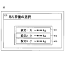
- FIG. 4 is a diagram showing an example of a suspension load selection screen (suspension load selection screen 410) displayed on the display device 50.
- the suspension load selection screen 410 has a relatively large (heavy) weight classification ("setting 1 large”), a medium weight classification (“setting 2 medium”), and a relatively small (light) weight classification ("setting 2 medium”).
- the selection icons 411 to 413 corresponding to each of the setting 3 small ") are displayed. The operator or the like can select the corresponding weight category by selecting and operating any one of the selection icons 411 to 413 through the input device 52.
- step S106 the controller 30 determines whether or not the suspension load selection operation has been performed.
- the controller 30 proceeds to step S108 when the suspension load selection operation is performed through the input device 52 on the suspension load selection screen, and waits until the selection operation is performed when the suspension load selection operation is not performed. ..
- the controller 30 may display an operation screen for inputting a specific numerical value of the suspended load (weight) through the input device 52 instead of the suspended load selection screen. .. Further, the controller 30 may estimate the load (weight) of the suspended load based on the detection information regarding the posture state of the attachment and the measured value of the pressure of the boom cylinder pressure sensor. In this case, the processing of steps S104 and S106 is omitted. Further, in step S106, if the suspension load selection operation is not performed even after a certain period of time has elapsed, the controller 30 automatically considers that the smallest (light) weight category has been selected, and steps S108. You may proceed to.
- step S108 the controller 30 changes the standby flow rate of the main pump 14 according to the weight classification of the suspension load, specifically, the suspension load selected on the suspension load selection screen, and proceeds to step S110.
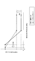
- FIG. 5 is a diagram showing the relationship between the operating amount of the hydraulic actuator (horizontal axis) and the discharge amount of the main pump 14 (vertical axis) in the normal mode and the lifting mode. Specifically, FIG. 5 shows the relationship between the negative control pressure (horizontal axis) in the normal mode and the lifting mode and the discharge amount (vertical axis) per unit time (for example, 1 minute) of the main pump 14. It is a figure which shows.
- the controller 30 increases the standby flow rate as compared with the case of the normal mode (arrow 501 in the figure).
- the discharge pressure of the main pump 14 at the start of operation of the boom cylinder 7 and arm cylinder 8 rises relatively quickly, so that the responsiveness of the attachment at the start of suspension operation can be improved. Therefore, the operator can perform the inching operation in the hanging operation even in the area where the operation amount of the operation device 26 is small.
- the amount of increase in the standby flow rate when the lifting mode is selected may be set so that the larger (heavier) the suspension load is, the larger the increase amount is.
- the controller 30 has a flow rate of the main pump 14 with respect to a change in the operation amount of the suspension operation (that is, the operation amount of at least one of the boom cylinder 7 and the arm cylinder 8).
- the inclination of the portion where the discharge amount per unit time of the main pump 14 increases according to the decrease in the negative controller pressure in the figure) is made smaller than in the normal mode.
- the standby flow rate is increased while keeping the negative control pressure at which the increase in the discharge amount per unit time of the main pump 14 is started is the same as in the case of the normal mode.
- the negative control pressure when the discharge amount per unit time of the main pump 14 reaches the maximum value is reduced (arrow 502 in the figure). Thereby, fine operability in the hanging work can be improved.
- the controller 30 is a standby of one of the main pumps 14L and 14R, which supplies hydraulic oil to the boom cylinder 7 and the arm cylinder 8 for driving the attachment. Only the flow rate may be increased compared to the case of the normal mode. In this case, only the standby flow rate of the main pump 14R, which is different from the main pump 14L that supplies hydraulic oil to the swing hydraulic motor 2A, may be increased. As a result, the standby flow rate of the main pump 14R remains the same as in the normal mode, so that the standby flow rate is tentatively increased and the operation of the upper swivel body 3 in response to the swivel operation is relative to the operator's assumption. It is possible to suppress the situation where the speed becomes faster.
- the controller 30 increases only the standby flow rate of the main pump 14R out of the main pumps 14L and 14R from the normal mode in the situation where the liftin mode is selected, while the traveling operation of the lower traveling body 1 is performed.
- the flow rate of the main pump 14R may be temporarily lowered, that is, returned to the normal mode.
- the lower traveling body 1 is driven by traveling hydraulic motors 1L and 1R having different left and right crawlers, and hydraulic oil is supplied to the traveling hydraulic motors 1L and 1R from the main pumps 14L and 14R, respectively. Therefore, when only the standby flow rate of the main pump 14R is relatively high, the lower traveling body 1 may not be able to travel properly (for example, it may not be able to operate straight ahead properly).
- the controller 30 increases the standby flow rate of both the main pumps 14L and 14R in the situation where the lifting mode is selected, while the controller 30 temporarily lowers the standby flow rate when the turning operation is performed. May be good.
- the upper swivel body 3 swivels faster than expected by the operator or the like in response to the swivel operation. Can be suppressed.
- step S110 the controller 30 determines whether or not the state in which the lifting mode is selected continues.
- the controller 30 proceeds to step S112 when the state in which the lifting mode is selected does not continue, that is, when the lifting mode is deselected and the normal mode is entered.
- step S112 the state in which the lifting mode is selected does not continue, that is, when the lifting mode is deselected and the normal mode is entered.
- step S110 the controller 30 waits until the lifting mode is released, that is, until it returns to the normal mode (step S110 is repeated).
- step S112 the controller 30 returns the standby flow rate to the normal state, that is, reduces the standby flow rate relatively from the lifting mode state, and ends the current process.
- the excavator 100 has a configuration in which various driven elements such as the lower traveling body 1, the upper swivel body 3, the boom 4, the arm 5, and the bucket 6 are all hydraulically driven.
- the unit may be electrically driven. That is, the configuration and the like disclosed in the above-described embodiment may be applied to a hybrid excavator, an electric excavator, and the like.
Abstract
Provided is a technology capable of further improving operability during suspension work in a shovel. A shovel 100 according to an embodiment of the present disclosure is provided with: a lower traveling body 1; an upper rotary body 3 rotatably mounted on the lower traveling body 1; an attachment including a boom 4 attached to the upper rotary body 3 and an arm 5 attached to the tip of the boom 4; a boom cylinder 7 for driving the boom 4; an arm cylinder 8 for driving the arm 5; a main pump 14 for supplying a working oil to the boom cylinder 7 and the arm cylinder 8; and a controller 30 for controlling the man pump 14, wherein when a suspension work using the main pump is performed, the controller 30 causes the standby flow rate of the main pump 14 to become greater than that in case of performing a work other than the suspension work.
Description
本開示は、ショベルに関する。
This disclosure relates to excavators.
従来、ショベルのアタッチメントを利用する吊り作業(クレーン作業とも称する)時の上部旋回体の旋回操作性を向上させる技術が知られている(例えば、特許文献1)。
Conventionally, a technique for improving the turning operability of the upper swinging body during suspension work (also referred to as crane work) using an excavator attachment is known (for example, Patent Document 1).
しかしながら、アタッチメントの操作性に改善の余地がある。
However, there is room for improvement in the operability of the attachment.
そこで、上記課題に鑑み、ショベルにおいて、吊り作業時の操作性を更に向上させることが可能な技術を提供することを目的とする。
Therefore, in view of the above problems, it is an object of the shovel to provide a technique capable of further improving the operability during the hanging work.
上記目的を達成するため、本開示の一実施形態では、
下部走行体と、
前記下部走行体に旋回自在に搭載される上部旋回体と、
前記上部旋回体に取り付けられるブーム、及び前記ブームの先端に取り付けられるアームを含むアタッチメントと、
前記ブームを駆動するブームシリンダと、
前記アームを駆動するアームシリンダと、
前記ブームシリンダ及び前記アームシリンダに作動油を供給する油圧ポンプと、
前記油圧ポンプを制御する制御装置と、を備え、
前記制御装置は、前記アタッチメントを利用する吊り作業が行われる場合、前記油圧ポンプのスタンバイ流量を、前記吊り作業以外の他の作業が行われる場合より大きくする、
ショベルが提供される。 In order to achieve the above object, in one embodiment of the present disclosure,
With the lower running body,
An upper swing body that is freely mounted on the lower running body and
An attachment including a boom attached to the upper swing body and an arm attached to the tip of the boom, and
The boom cylinder that drives the boom and
An arm cylinder that drives the arm and
A hydraulic pump that supplies hydraulic oil to the boom cylinder and the arm cylinder,
A control device for controlling the hydraulic pump is provided.
When the suspension work using the attachment is performed, the control device increases the standby flow rate of the hydraulic pump as compared with the case where other work other than the suspension work is performed.
A shovel is provided.
また、本開示の他の実施形態では、
下部走行体と、
前記下部走行体に旋回自在に搭載される上部旋回体と、
前記上部旋回体に取り付けられるブーム、及び前記ブームの先端に取り付けられるアームを含むアタッチメントと、
前記ブームを駆動するブームシリンダと、
前記アームを駆動するアームシリンダと、
前記ブームシリンダ及び前記アームシリンダに作動油を供給する油圧ポンプと、
前記油圧ポンプを制御する制御装置と、を備え、
前記制御装置は、吊り荷重の大小、ブームシリンダの負荷状態、ショベルの所定の作業モードの別、前記下部走行体の操作状態、及び前記上部旋回体の旋回状態の少なくとも一つに応じて、前記油圧ポンプのスタンバイ流量を変化させる、
ショベルが提供される。 Also, in other embodiments of the present disclosure,
With the lower running body,
An upper swing body that is freely mounted on the lower running body and
An attachment including a boom attached to the upper swing body and an arm attached to the tip of the boom, and
The boom cylinder that drives the boom and
An arm cylinder that drives the arm and
A hydraulic pump that supplies hydraulic oil to the boom cylinder and the arm cylinder,
A control device for controlling the hydraulic pump is provided.
The control device is described according to at least one of the magnitude of the suspension load, the load state of the boom cylinder, the predetermined working mode of the excavator, the operating state of the lower traveling body, and the turning state of the upper swing body. Change the standby flow rate of the hydraulic pump,
A shovel is provided.
上述の実施形態によれば、ショベルにおいて、吊り作業時の操作性を更に向上させることが可能な技術を提供することができる。
According to the above-described embodiment, it is possible to provide a technique capable of further improving the operability during the suspension work in the excavator.
以下、図面を参照して実施形態について説明する。
Hereinafter, embodiments will be described with reference to the drawings.
[ショベルの概要]
まず、図1を参照して、本実施形態に係るショベル100の概要について説明をする。 [Outline of excavator]
First, the outline of theexcavator 100 according to the present embodiment will be described with reference to FIG.
まず、図1を参照して、本実施形態に係るショベル100の概要について説明をする。 [Outline of excavator]
First, the outline of the
図1は、本実施形態に係るショベル100の側面図である。
FIG. 1 is a side view of the excavator 100 according to the present embodiment.
本実施形態に係るショベル100は、下部走行体1と、旋回機構2を介して旋回自在に下部走行体1に搭載される上部旋回体3と、アタッチメント(作業装置)としてのブーム4、アーム5、及びバケット6と、キャビン10とを備える。
The excavator 100 according to the present embodiment includes a lower traveling body 1, an upper swivel body 3 that is swivelably mounted on the lower traveling body 1 via a swivel mechanism 2, a boom 4 as an attachment (working device), and an arm 5. , And a bucket 6 and a cabin 10.
下部走行体1は、例えば、左右一対のクローラを含み、それぞれのクローラが走行油圧モータ1L,1R(図2参照)で油圧駆動されることにより、ショベル100を走行(自走)させる。
The lower traveling body 1 includes, for example, a pair of left and right crawlers, and the excavator 100 is driven (self-propelled) by hydraulically driving each crawler with the traveling hydraulic motors 1L and 1R (see FIG. 2).
上部旋回体3は、旋回油圧モータ2A(図2参照)で駆動されることにより、下部走行体1に対して旋回する。
The upper swing body 3 turns with respect to the lower traveling body 1 by being driven by the swing hydraulic motor 2A (see FIG. 2).
ブーム4は、上部旋回体3の前部中央に俯仰可能に枢着され、ブーム4の先端には、アーム5が上下回動可能に枢着され、アーム5の先端には、バケット6が上下回動可能に枢着される。ブーム4、アーム5、及びバケット6は、油圧アクチュエータとしてのブームシリンダ7、アームシリンダ8、及びバケットシリンダ9によりそれぞれ油圧駆動される。
The boom 4 is pivotally attached to the center of the front portion of the upper swing body 3 so as to be vertically movable, an arm 5 is pivotally attached to the tip of the boom 4 so as to be vertically rotatable, and a bucket 6 is vertically attached to the tip of the arm 5. It is rotatably pivoted. The boom 4, arm 5, and bucket 6 are hydraulically driven by the boom cylinder 7, arm cylinder 8, and bucket cylinder 9 as hydraulic actuators, respectively.
また、エンドアタッチメントとしてのバケット6には、アタッチメントを利用する吊り作業(クレーン作業)用のフック80が取り付けられる。フック80は、基端が、アーム5とバケット6との間を連結するバケットピンに回動可能に連結される。これにより、フック80は、掘削作業等の吊り作業以外の作業が行われる場合、2本のバケットリンクの間に形成されるフック収納空間に収納される。
Further, a hook 80 for hanging work (crane work) using the attachment is attached to the bucket 6 as an end attachment. The hook 80 is rotatably connected to a bucket pin whose base end connects between the arm 5 and the bucket 6. As a result, the hook 80 is stored in the hook storage space formed between the two bucket links when a work other than the hanging work such as excavation work is performed.
キャビン10は、オペレータ等が搭乗する操縦室であり、上部旋回体3の前部左側に搭載される。
The cabin 10 is a cockpit on which an operator or the like is boarded, and is mounted on the front left side of the upper swivel body 3.
ショベル100は、キャビン10に搭乗するオペレータの操作に応じて、下部走行体1(左右のクローラ)、上部旋回体3、ブーム4、アーム5、及びバケット6等の被駆動要素を動作させる。
The excavator 100 operates driven elements such as the lower traveling body 1 (left and right crawlers), the upper turning body 3, the boom 4, the arm 5, and the bucket 6 in response to the operation of the operator boarding the cabin 10.
また、ショベル100は、キャビン10に搭乗するオペレータによって操作可能に構成されるのに代えて、或いは、加えて、ショベル100の外部から遠隔操作(リモート操作)が可能に構成されてもよい。ショベル100が遠隔操作される場合、キャビン10の内部は、無人状態であってもよい。以下、オペレータの操作には、キャビン10のオペレータの操作装置26に対する操作、及び外部のオペレータの遠隔操作の少なくとも一方が含まれる前提で説明を進める。
Further, the excavator 100 may be configured to be operable by an operator boarding the cabin 10, or may be configured to be remotely controlled (remote operation) from the outside of the excavator 100. When the excavator 100 is remotely controlled, the inside of the cabin 10 may be unmanned. Hereinafter, the description will proceed on the premise that the operator's operation includes at least one of the operation of the cabin 10 with respect to the operation device 26 and the remote control of the external operator.
遠隔操作には、例えば、所定の外部装置で行われるショベル100のアクチュエータに関する操作入力によって、ショベル100が操作される態様が含まれる。この場合、ショベル100は、例えば、上部旋回体3の周囲を撮像する撮像装置が出力する画像情報(撮像画像)を外部装置に送信し、画像情報は、外部装置に設けられる表示装置(以下、「遠隔操作用表示装置」)に表示されてよい。また、ショベル100のキャビン10の内部の後述する表示装置50に表示される各種の情報画像(情報画面)は、同様に、外部装置の遠隔操作用表示装置にも表示されてよい。これにより、外部装置のオペレータは、例えば、遠隔操作用表示装置に表示されるショベル100の周囲の様子を表す撮像画像や情報画面等の表示内容を確認しながら、ショベル100を遠隔操作することができる。そして、ショベル100は、外部装置から受信される、遠隔操作の内容を表す遠隔操作信号に応じて、アクチュエータを動作させ、下部走行体1(左右のクローラ)、上部旋回体3、ブーム4、アーム5、及びバケット6等の被駆動要素を駆動してよい。
The remote control includes, for example, a mode in which the shovel 100 is operated by an operation input related to the actuator of the shovel 100 performed by a predetermined external device. In this case, the excavator 100 transmits, for example, image information (image captured) output by an imaging device that images the surroundings of the upper swivel body 3 to an external device, and the image information is transmitted to a display device provided in the external device (hereinafter, hereinafter, It may be displayed on the "remote control display device"). Further, various information images (information screens) displayed on the display device 50 described later inside the cabin 10 of the excavator 100 may be similarly displayed on the remote control display device of the external device. As a result, the operator of the external device can remotely control the excavator 100 while checking the display contents such as the captured image and the information screen showing the surrounding state of the excavator 100 displayed on the remote control display device, for example. it can. Then, the excavator 100 operates the actuator in response to the remote control signal indicating the content of the remote control received from the external device, and causes the lower traveling body 1 (left and right crawlers), the upper turning body 3, the boom 4, and the arm. Driven elements such as 5 and the bucket 6 may be driven.
また、遠隔操作には、例えば、ショベル100の周囲の人(例えば、作業者)のショベル100に対する外部からの音声入力やジェスチャ入力等によって、ショベル100が操作される態様が含まれてよい。具体的には、ショベル100は、ショベル100に搭載される音声入力装置(例えば、マイクロフォン)やジェスチャ入力装置(例えば、撮像装置)等を通じて、周囲の作業者等により発話される音声や作業者等により行われるジェスチャ等を認識する。そして、ショベル100は、認識した音声やジェスチャ等の内容に応じて、アクチュエータを動作させ、下部走行体1(左右のクローラ)、上部旋回体3、ブーム4、アーム5、及びバケット6等の被駆動要素を駆動してよい。
Further, the remote control may include a mode in which the excavator 100 is operated by, for example, an external voice input or a gesture input to the excavator 100 by a person (for example, a worker) around the excavator 100. Specifically, the excavator 100 is a voice, a worker, or the like spoken by a surrounding worker or the like through a voice input device (for example, a microphone) or a gesture input device (for example, an image pickup device) mounted on the excavator 100. Recognize the gestures performed by. Then, the excavator 100 operates an actuator according to the recognized voice, gesture, or the like, and covers the lower traveling body 1 (left and right crawlers), the upper rotating body 3, the boom 4, the arm 5, the bucket 6, and the like. The drive element may be driven.
また、ショベル100は、オペレータの操作の内容に依らず、自動でアクチュエータを動作させてもよい。これにより、ショベル100は、下部走行体1(左右のクローラ)、上部旋回体3、ブーム4、アーム5、及びバケット6等の被駆動要素の少なくとも一部を自動で動作させる機能(いわゆる「自動運転機能」或いは「マシンコントロール機能」)を実現する。
Further, the excavator 100 may automatically operate the actuator regardless of the content of the operator's operation. As a result, the excavator 100 has a function of automatically operating at least a part of driven elements such as the lower traveling body 1 (left and right crawlers), the upper rotating body 3, the boom 4, the arm 5, and the bucket 6 (so-called "automatic"). Realize "driving function" or "machine control function").
自動運転機能には、オペレータの操作装置26に対する操作や遠隔操作に応じて、操作対象の被駆動要素(油圧アクチュエータ)以外の被駆動要素(油圧アクチュエータ)を自動で動作させる機能(いわゆる「半自動運機能」)が含まれてよい。また、自動運転機能には、オペレータの操作装置26に対する操作や遠隔操作がない前提で、複数の被駆動要素(油圧アクチュエータ)の少なくとも一部を自動で動作させる機能(いわゆる「完全自動運転機能」)が含まれてよい。ショベル100において、完全自動運転機能が有効な場合、キャビン10の内部は無人状態であってよい。また、半自動運転機能や完全自動運転機能等には、自動運転の対象の被駆動要素(油圧アクチュエータ)の動作内容が予め規定されるルールに従って自動的に決定される態様が含まれてよい。また、半自動運転機能や完全自動運転機能等には、ショベル100が自律的に各種の判断を行い、その判断結果に沿って、自律的に自動運転の対象の被駆動要素(油圧アクチュエータ)の動作内容が決定される態様(いわゆる「自律運転機能」)が含まれてもよい。
The automatic operation function is a function (so-called "semi-automatic operation") in which a driven element (hydraulic actuator) other than the driven element (hydraulic actuator) to be operated is automatically operated in response to an operator's operation on the operating device 26 or a remote control. Function ") may be included. Further, the automatic operation function is a function (so-called "fully automatic operation function") in which at least a part of a plurality of driven elements (hydraulic actuators) is automatically operated on the premise that there is no operation or remote control of the operator's operation device 26. ) May be included. When the fully automatic driving function is enabled in the excavator 100, the inside of the cabin 10 may be unmanned. Further, the semi-automatic operation function, the fully automatic operation function, and the like may include a mode in which the operation content of the driven element (hydraulic actuator) to be automatically operated is automatically determined according to a predetermined rule. Further, for the semi-automatic driving function, the fully automatic driving function, etc., the excavator 100 autonomously makes various judgments, and according to the judgment results, the driven element (hydraulic actuator) to be automatically operated operates autonomously. A mode in which the content is determined (so-called "autonomous driving function") may be included.
[ショベルの構成]
次に、図1に加えて、図2を参照して、ショベル100の構成について説明する。 [Excavator configuration]
Next, the configuration of theexcavator 100 will be described with reference to FIG. 2 in addition to FIG.
次に、図1に加えて、図2を参照して、ショベル100の構成について説明する。 [Excavator configuration]
Next, the configuration of the
図2は、本実施形態に係るショベル100の構成の一例を示す図である。
FIG. 2 is a diagram showing an example of the configuration of the excavator 100 according to the present embodiment.
尚、図中、機械的動力ラインは二重線、高圧油圧ラインは実線、パイロットラインは破線、電気駆動・制御ラインは点線でそれぞれ示される。
In the figure, the mechanical power line is indicated by a double line, the high-pressure hydraulic line is indicated by a solid line, the pilot line is indicated by a broken line, and the electric drive / control line is indicated by a dotted line.
<油圧駆動系>
本実施形態に係るショベル100の油圧駆動系は、上述の如く、下部走行体1、上部旋回体3、ブーム4、アーム5、及びバケット6等の被駆動要素のそれぞれを油圧駆動する油圧アクチュエータを含む。油圧アクチュエータには、走行油圧モータ1L,1R、旋回油圧モータ2A、ブームシリンダ7、アームシリンダ8、及びバケットシリンダ9等が含まれる。また、本実施形態に係るショベル100の油圧駆動系は、エンジン11と、メインポンプ14L,14Rと、コントロールバルブ17とを含む。 <Hydraulic drive system>
As described above, the hydraulic drive system of theexcavator 100 according to the present embodiment hydraulically drives each of the driven elements such as the lower traveling body 1, the upper swing body 3, the boom 4, the arm 5, and the bucket 6. Including. The hydraulic actuator includes a traveling hydraulic motor 1L, 1R, a swing hydraulic motor 2A, a boom cylinder 7, an arm cylinder 8, a bucket cylinder 9, and the like. Further, the hydraulic drive system of the excavator 100 according to the present embodiment includes an engine 11, main pumps 14L and 14R, and a control valve 17.
本実施形態に係るショベル100の油圧駆動系は、上述の如く、下部走行体1、上部旋回体3、ブーム4、アーム5、及びバケット6等の被駆動要素のそれぞれを油圧駆動する油圧アクチュエータを含む。油圧アクチュエータには、走行油圧モータ1L,1R、旋回油圧モータ2A、ブームシリンダ7、アームシリンダ8、及びバケットシリンダ9等が含まれる。また、本実施形態に係るショベル100の油圧駆動系は、エンジン11と、メインポンプ14L,14Rと、コントロールバルブ17とを含む。 <Hydraulic drive system>
As described above, the hydraulic drive system of the
エンジン11は、油圧駆動系におけるメイン動力源であり、例えば、上部旋回体3の後部に搭載される。具体的には、エンジン11は、コントローラ30による制御の下、予め設定される目標回転数で一定回転し、メインポンプ14L,14R及びパイロットポンプ15を駆動する。エンジン11は、例えば、軽油を燃料とするディーゼルエンジンである。
The engine 11 is the main power source in the hydraulic drive system, and is mounted on the rear part of the upper swing body 3, for example. Specifically, the engine 11 rotates constantly at a preset target rotation speed under the control of the controller 30 to drive the main pumps 14L and 14R and the pilot pump 15. The engine 11 is, for example, a diesel engine that uses light oil as fuel.
メインポンプ14L,14Rは、それぞれ、例えば、エンジン11と同様、上部旋回体3の後部に搭載され、高圧油圧ラインを通じてコントロールバルブ17に作動油を供給する。メインポンプ14L,14Rは、それぞれ、上述の如く、エンジン11により駆動される。メインポンプ14L,14Rは、それぞれ、例えば、可変容量式油圧ポンプであり、後述するコントローラ30による制御の下、レギュレータ13L,13Rにより斜板の角度(傾転角)が調整されることでピストンのストローク長が調整され、吐出流量(吐出圧)が制御されうる。
The main pumps 14L and 14R are mounted on the rear part of the upper swing body 3 like the engine 11, respectively, and supply hydraulic oil to the control valve 17 through the high-pressure hydraulic line. The main pumps 14L and 14R are each driven by the engine 11 as described above. The main pumps 14L and 14R are, for example, variable displacement hydraulic pumps, respectively, and the angle (tilt angle) of the swash plate is adjusted by the regulators 13L and 13R under the control of the controller 30, which will be described later, to adjust the angle of the piston. The stroke length can be adjusted and the discharge flow rate (discharge pressure) can be controlled.
コントロールバルブ17は、例えば、上部旋回体3の中央部に搭載され、オペレータ等による被駆動要素(対応する油圧アクチュエータ)に関する操作(操作装置26に対する操作や遠隔操作)や自動運転機能に対応する被駆動要素(油圧アクチュエータ)に関する操作指令に応じて、油圧駆動系の制御を行う油圧制御装置である。コントロールバルブ17は、上述の如く、高圧油圧ラインを介してメインポンプ14L,14Rと接続され、メインポンプ14L,14Rから供給される作動油を、オペレータによる被駆動要素に関する操作(操作装置26の操作や遠隔操作)の状態や自動運転機能に対応する被駆動要素に関する操作指令の内容に応じて、油圧アクチュエータである走行油圧モータ1L(左側のクローラ用),1R(右側のクローラ用)、旋回油圧モータ2A、ブームシリンダ7、アームシリンダ8、及びバケットシリンダ9に選択的に供給する。具体的には、コントロールバルブ17は、メインポンプ14L,14Rから油圧アクチュエータのそれぞれに供給される作動油の流量と流れる方向を制御する制御弁171,172,173,174,175L,175R,176L,176Rを含む。
The control valve 17 is mounted in the central portion of the upper swing body 3, for example, and is a cover that corresponds to an operation (operation or remote control on the operation device 26) related to a driven element (corresponding hydraulic actuator) by an operator or the like and an automatic operation function. It is a hydraulic control device that controls the hydraulic drive system in response to an operation command related to a drive element (hydraulic actuator). As described above, the control valve 17 is connected to the main pumps 14L and 14R via the high-pressure hydraulic line, and the hydraulic oil supplied from the main pumps 14L and 14R is operated by the operator regarding the driven element (operation of the operating device 26). Depending on the state of (remote operation) and the content of the operation command regarding the driven element corresponding to the automatic operation function, the traveling hydraulic motor 1L (for the left crawler), 1R (for the right crawler), and the turning hydraulic pressure are hydraulic actuators. It is selectively supplied to the motor 2A, the boom cylinder 7, the arm cylinder 8, and the bucket cylinder 9. Specifically, the control valve 17 is a control valve 171, 172, 173, 174, 175L, 175R, 176L that controls the flow rate and the flow direction of the hydraulic oil supplied from the main pumps 14L and 14R to the hydraulic actuators, respectively. Includes 176R.
ショベル100の油圧駆動系は、エンジン11により駆動されるメインポンプ14L,14Rのそれぞれから、センタバイパス油路C1L,C1R、パラレル油路C2L,C2Rを経て作動油タンクまで作動油を循環させる。
The hydraulic drive system of the excavator 100 circulates hydraulic oil from the main pumps 14L and 14R driven by the engine 11 to the hydraulic oil tank via the center bypass oil passages C1L and C1R and the parallel oil passages C2L and C2R, respectively.
センタバイパス油路C1Lは、メインポンプ14Lを起点として、コントロールバルブ17内に配置される制御弁171,173,175L,176Lを順に通過し、作動油タンクに至る。
The center bypass oil passage C1L starts from the main pump 14L, passes through the control valves 171, 173, 175L, and 176L arranged in the control valve 17 in order, and reaches the hydraulic oil tank.
センタバイパス油路C1Rは、メインポンプ14Rを起点として、コントロールバルブ17内に配置される制御弁172,174,175R,176Rを順に通過し、作動油タンクに至る。
The center bypass oil passage C1R starts from the main pump 14R, passes through the control valves 172, 174, 175R, and 176R arranged in the control valve 17 in order, and reaches the hydraulic oil tank.
制御弁171は、メインポンプ14Lが吐出する作動油を走行油圧モータ1Lへ供給し、且つ、走行油圧モータ1Lが吐出する作動油を作動油タンクに排出させるスプール弁である。
The control valve 171 is a spool valve that supplies the hydraulic oil discharged by the main pump 14L to the traveling hydraulic motor 1L and discharges the hydraulic oil discharged by the traveling hydraulic motor 1L to the hydraulic oil tank.
制御弁172は、メインポンプ14Rが吐出する作動油を走行油圧モータ1Rへ供給し、且つ、走行油圧モータ1Rが吐出する作動油を作動油タンクへ排出させるスプール弁である。
The control valve 172 is a spool valve that supplies the hydraulic oil discharged by the main pump 14R to the traveling hydraulic motor 1R and discharges the hydraulic oil discharged by the traveling hydraulic motor 1R to the hydraulic oil tank.
制御弁173は、メインポンプ14Lが吐出する作動油を旋回油圧モータ2Aへ供給し、且つ、旋回油圧モータ2Aが吐出する作動油を作動油タンクへ排出させるスプール弁である。
The control valve 173 is a spool valve that supplies the hydraulic oil discharged by the main pump 14L to the swing hydraulic motor 2A and discharges the hydraulic oil discharged by the swing hydraulic motor 2A to the hydraulic oil tank.
制御弁174は、メインポンプ14Rが吐出する作動油をバケットシリンダ9へ供給し、且つ、バケットシリンダ9内の作動油を作動油タンクへ排出させるスプール弁である。
The control valve 174 is a spool valve that supplies the hydraulic oil discharged by the main pump 14R to the bucket cylinder 9 and discharges the hydraulic oil in the bucket cylinder 9 to the hydraulic oil tank.
制御弁175L,175Rは、それぞれ、メインポンプ14L,14Rが吐出する作動油をブームシリンダ7へ供給し、且つ、ブームシリンダ7内の作動油を作動油タンクへ排出させるスプール弁である。
The control valves 175L and 175R are spool valves that supply the hydraulic oil discharged by the main pumps 14L and 14R to the boom cylinder 7 and discharge the hydraulic oil in the boom cylinder 7 to the hydraulic oil tank, respectively.
制御弁176L,176Rは、メインポンプ14L,14Rが吐出する作動油をアームシリンダ8へ供給し、且つ、アームシリンダ8内の作動油を作動油タンクへ排出させるスプール弁である。
The control valves 176L and 176R are spool valves that supply the hydraulic oil discharged by the main pumps 14L and 14R to the arm cylinder 8 and discharge the hydraulic oil in the arm cylinder 8 to the hydraulic oil tank.
制御弁171,172,173,174,175L,175R,176L,176Rは、それぞれ、パイロットポートに作用するパイロット圧に応じて、油圧アクチュエータに給排される作動油の流量を調整したり、流れる方向を切り換えたりする。
The control valves 171, 172, 173, 174, 175L, 175R, 176L, and 176R adjust the flow rate of the hydraulic oil supplied to and discharged from the hydraulic actuator according to the pilot pressure acting on the pilot port, and the flow direction, respectively. To switch.
パラレル油路C2Lは、センタバイパス油路C1Lと並列的に、制御弁171,173,175L,176Lにメインポンプ14Lの作動油を供給する。具体的には、パラレル油路C2Lは、制御弁171の上流側でセンタバイパス油路C1Lから分岐し、制御弁171,173,175L,176Rのそれぞれに並列してメインポンプ14Lの作動油を供給可能に構成される。これにより、パラレル油路C2Lは、制御弁171,173,175Lの何れかによってセンタバイパス油路C1Lを通る作動油の流れが制限或いは遮断された場合に、より下流の制御弁に作動油を供給できる。
The parallel oil passage C2L supplies the hydraulic oil of the main pump 14L to the control valves 171, 173, 175L, and 176L in parallel with the center bypass oil passage C1L. Specifically, the parallel oil passage C2L branches from the center bypass oil passage C1L on the upstream side of the control valve 171 and supplies the hydraulic oil of the main pump 14L in parallel with the control valves 171, 173, 175L, and 176R, respectively. It is configured to be possible. As a result, the parallel oil passage C2L supplies the hydraulic oil to the control valve further downstream when the flow of the hydraulic oil through the center bypass oil passage C1L is restricted or blocked by any of the control valves 171, 173, and 175L. it can.
パラレル油路C2Rは、センタバイパス油路C1Rと並列的に、制御弁172,174,175R,176Rにメインポンプ14Rの作動油を供給する。具体的には、パラレル油路C2Rは、制御弁172の上流側でセンタバイパス油路C1Rから分岐し、制御弁172,174,175R,176Rのそれぞれに並列してメインポンプ14Rの作動油を供給可能に構成される。パラレル油路C2Rは、制御弁172,174,175Rの何れかによってセンタバイパス油路C1Rを通る作動油の流れが制限或いは遮断された場合に、より下流の制御弁に作動油を供給できる。
The parallel oil passage C2R supplies the hydraulic oil of the main pump 14R to the control valves 172, 174, 175R and 176R in parallel with the center bypass oil passage C1R. Specifically, the parallel oil passage C2R branches from the center bypass oil passage C1R on the upstream side of the control valve 172, and supplies the hydraulic oil of the main pump 14R in parallel with the control valves 172, 174, 175R, and 176R, respectively. It is configured to be possible. The parallel oil passage C2R can supply the hydraulic oil to the control valve further downstream when the flow of the hydraulic oil through the center bypass oil passage C1R is restricted or blocked by any of the control valves 172, 174, and 175R.
<操作系>
本実施形態に係るショベル100の操作系は、パイロットポンプ15と、操作装置26とを含む。 <Operation system>
The operating system of theexcavator 100 according to the present embodiment includes a pilot pump 15 and an operating device 26.
本実施形態に係るショベル100の操作系は、パイロットポンプ15と、操作装置26とを含む。 <Operation system>
The operating system of the
パイロットポンプ15は、例えば、エンジン11と同様、上部旋回体3の後部に搭載され、パイロットライン25を介して操作装置26にパイロット圧を供給する。パイロットポンプ15は、例えば、固定容量式油圧ポンプであり、上述の如く、エンジン11により駆動される。
The pilot pump 15 is mounted on the rear part of the upper swing body 3 like the engine 11, and supplies the pilot pressure to the operating device 26 via the pilot line 25, for example. The pilot pump 15 is, for example, a fixed-capacity hydraulic pump, and is driven by the engine 11 as described above.
操作装置26は、例えば、キャビン10の操縦席付近に設けられ、オペレータ等が各種被駆動要素(下部走行体1、上部旋回体3、ブーム4、アーム5、バケット6等)の操作を行うための操作入力手段である。換言すれば、操作装置26は、それぞれの被駆動要素を駆動する油圧アクチュエータ(即ち、走行油圧モータ1L,1R、旋回油圧モータ2A、ブームシリンダ7、アームシリンダ8、バケットシリンダ9等)の操作を行うための操作入力手段である。操作装置26は、例えば、上部旋回体3、ブーム4、アーム5、バケット6のそれぞれを操作する4つのレバー装置を含む。また、操作装置26は、例えば、下部走行体1の左側のクローラ及び右側のクローラ(つまり、走行油圧モータ1L,1R)のそれぞれを操作する2つのペダル装置を含む。
The operating device 26 is provided near the driver's seat of the cabin 10, for example, so that an operator or the like can operate various driven elements (lower traveling body 1, upper turning body 3, boom 4, arm 5, bucket 6, etc.). It is an operation input means of. In other words, the operating device 26 operates hydraulic actuators (that is, traveling hydraulic motors 1L, 1R, swivel hydraulic motor 2A, boom cylinder 7, arm cylinder 8, bucket cylinder 9, etc.) that drive each driven element. It is an operation input means for performing. The operating device 26 includes, for example, four lever devices for operating each of the upper swing body 3, the boom 4, the arm 5, and the bucket 6. Further, the operating device 26 includes, for example, two pedal devices for operating the left crawler and the right crawler (that is, the traveling hydraulic motors 1L and 1R) of the lower traveling body 1.
図2に示すように、操作装置26は、例えば、その操作内容に対応するパイロット圧を有する作動油を出力する油圧パイロット式である。具体的には、操作装置26に含まれるレバー装置やペダル装置等は、パイロットラインを介して、コントロールバルブ17にそれぞれ接続され、パイロットポンプ25から供給される作動油を用いて、その操作内容に対応するパイロット圧をコントロールバルブ17に向けて出力する。これにより、コントロールバルブ17には、操作装置26における下部走行体1、上部旋回体3、ブーム4、アーム5、及びバケット6等の操作状態に応じたパイロット信号(パイロット圧)が入力される。具体的には、左側のクローラ(走行油圧モータ1L)及び右側クローラ(走行油圧モータ1R)を操作する二つのペダル装置の二次側のパイロット圧は、それぞれ、制御弁171,172のパイロットポートに作用する。また、上部旋回体3(旋回油圧モータ2A)を操作するレバー装置の二次側のパイロット圧は、制御弁173のパイロットポートに作用する。また、ブーム4(ブームシリンダ7)を操作するレバー装置の二次側のパイロット圧は、制御弁175L,175Rのパイロットポートに作用する。また、アーム5(アームシリンダ8)を操作するレバー装置の二次側のパイロット圧は、制御弁176L,176Rのパイロットポートに作用する。また、バケット6(バケットシリンダ9)を操作するレバー装置の二次側のパイロット圧は、制御弁174のパイロットポートに作用する。そのため、コントロールバルブ17は、操作装置26における操作状態に応じて、それぞれの油圧アクチュエータを駆動することができる。
As shown in FIG. 2, the operating device 26 is, for example, a hydraulic pilot type that outputs hydraulic oil having a pilot pressure corresponding to the operation content. Specifically, the lever device, pedal device, and the like included in the operation device 26 are connected to the control valve 17 via the pilot line, respectively, and the hydraulic oil supplied from the pilot pump 25 is used for the operation content. The corresponding pilot pressure is output toward the control valve 17. As a result, a pilot signal (pilot pressure) according to the operating state of the lower traveling body 1, the upper swinging body 3, the boom 4, the arm 5, the bucket 6 and the like in the operating device 26 is input to the control valve 17. Specifically, the pilot pressures on the secondary side of the two pedal devices that operate the left crawler (running hydraulic motor 1L) and the right crawler (running hydraulic motor 1R) are applied to the pilot ports of the control valves 171 and 172, respectively. It works. Further, the pilot pressure on the secondary side of the lever device that operates the upper swing body 3 (swing hydraulic motor 2A) acts on the pilot port of the control valve 173. Further, the pilot pressure on the secondary side of the lever device that operates the boom 4 (boom cylinder 7) acts on the pilot ports of the control valves 175L and 175R. Further, the pilot pressure on the secondary side of the lever device that operates the arm 5 (arm cylinder 8) acts on the pilot ports of the control valves 176L and 176R. Further, the pilot pressure on the secondary side of the lever device that operates the bucket 6 (bucket cylinder 9) acts on the pilot port of the control valve 174. Therefore, the control valve 17 can drive each hydraulic actuator according to the operating state of the operating device 26.
また、操作装置26は、例えば、その操作内容に対応する電気信号(以下、「操作信号」)を出力する電気式であってもよい。この場合、操作装置26からの操作信号は、コントローラ30に入力され、コントローラ30は、入力される操作信号に応じて、コントロールバルブ17内の各制御弁を制御することにより、操作装置26に対する操作内容に応じた、各種油圧アクチュエータの動作を実現する。例えば、コントロールバルブ17内の制御弁は、コントローラ30からの指令により駆動する電磁ソレノイド式スプール弁であってよい。また、例えば、パイロットポンプ15と各制御弁のパイロットポートとの間には、コントローラ30からの制御指令に応じて動作する油圧制御弁(以下、「操作用制御弁」)が配置されてもよい。この場合、電気式の操作装置26を用いた手動操作が行われると、コントローラ30は、その操作量(例えば、レバー操作量)に対応する制御指令によって、操作用制御弁を制御しパイロット圧を増減させることで、操作装置26に対する操作内容に合わせて、各制御弁を動作させることができる。
Further, the operation device 26 may be, for example, an electric type that outputs an electric signal (hereinafter, “operation signal”) corresponding to the operation content. In this case, the operation signal from the operation device 26 is input to the controller 30, and the controller 30 controls each control valve in the control valve 17 according to the input operation signal to operate the operation device 26. Realize the operation of various hydraulic actuators according to the content. For example, the control valve in the control valve 17 may be an electromagnetic solenoid type spool valve driven by a command from the controller 30. Further, for example, a hydraulic control valve (hereinafter, “operation control valve”) that operates in response to a control command from the controller 30 may be arranged between the pilot pump 15 and the pilot port of each control valve. .. In this case, when a manual operation is performed using the electric operation device 26, the controller 30 controls the operation control valve by a control command corresponding to the operation amount (for example, the lever operation amount) to control the pilot pressure. By increasing or decreasing, each control valve can be operated according to the operation content for the operating device 26.
<制御系>
本実施形態に係るショベル100の制御系は、コントローラ30を含む。また、本実施形態に係るショベル100の制御系は、レギュレータ13L,13Rと、ネガティブコントロール絞り(以下、「ネガコン絞り」)18L,18Rと、ネガコン圧センサ19L,19Rと、吐出圧センサ28と、操作圧センサ29と、表示装置50と、入力装置52とを含む。 <Control system>
The control system of theexcavator 100 according to the present embodiment includes the controller 30. Further, the control system of the excavator 100 according to the present embodiment includes regulators 13L and 13R, negative control diaphragms (hereinafter, “negative control diaphragms”) 18L and 18R, negative control pressure sensors 19L and 19R, discharge pressure sensors 28, and the like. It includes an operating pressure sensor 29, a display device 50, and an input device 52.
本実施形態に係るショベル100の制御系は、コントローラ30を含む。また、本実施形態に係るショベル100の制御系は、レギュレータ13L,13Rと、ネガティブコントロール絞り(以下、「ネガコン絞り」)18L,18Rと、ネガコン圧センサ19L,19Rと、吐出圧センサ28と、操作圧センサ29と、表示装置50と、入力装置52とを含む。 <Control system>
The control system of the
コントローラ30(制御装置の一例)は、ショベル100に関する各種制御を行う。コントローラ30は、その機能が任意のハードウェア、或いは、任意のハードウェア及びソフトウェアの組み合わせ等により実現されてよい。例えば、コントローラ30は、CPU(Central Processing Unit)等のプロセッサ、RAM(Random Access Memory)等のメモリ装置、ROM(Read Only Memory)等の補助記憶装置、及び各種入出力用のインタフェース装置等を含むコンピュータを中心に構成される。コントローラ30は、例えば、補助記憶装置にインストールされる一以上のプログラムをCPU上で実行することにより各種機能を実現する。
The controller 30 (an example of a control device) performs various controls related to the excavator 100. The function of the controller 30 may be realized by any hardware, or a combination of any hardware and software. For example, the controller 30 includes a processor such as a CPU (Central Processing Unit), a memory device such as a RAM (Random Access Memory), an auxiliary storage device such as a ROM (Read Only Memory), and an interface device for various input / output. It consists mainly of a computer. The controller 30 realizes various functions by executing, for example, one or more programs installed in the auxiliary storage device on the CPU.
例えば、コントローラ30は、オペレータ等の操作により予め設定される作業モード(例えば、後述のリフティングモード)等に基づき、目標回転数を設定し、直接、或いは、エンジン11の専用の制御装置を介して、エンジン11を一定回転させる駆動制御を行う。ショベル100には、例えば、掘削作業等の通常の作業を行うための通常モードと、アタッチメント(フック80)を利用する吊り作業に対応する作業モード(以下、「リフティングモード」)とが予め規定され、入力装置52を通じたオペレータ等の操作により選択可能であってよい。この場合、コントローラ30は、リフティングモードが選択された場合に、エンジン11の目標回転数を相対的に低く設定する。これにより、吊り作業において、アタッチメントの動作が相対的に遅くなる。そのため、オペレータは、吊り操作がし易くなる。
For example, the controller 30 sets a target rotation speed based on a work mode (for example, a lifting mode described later) or the like preset by an operation of an operator or the like, and directly or via a dedicated control device of the engine 11. , Drive control is performed to rotate the engine 11 at a constant speed. For example, the excavator 100 is defined in advance as a normal mode for performing a normal work such as excavation work and a work mode (hereinafter, "lifting mode") corresponding to a hanging work using an attachment (hook 80). , It may be selectable by an operation of an operator or the like through the input device 52. In this case, the controller 30 sets the target rotation speed of the engine 11 to be relatively low when the lifting mode is selected. As a result, the operation of the attachment becomes relatively slow in the hanging work. Therefore, the operator can easily perform the hanging operation.
また、例えば、コントローラ30は、レギュレータ13L,13Rを制御し、メインポンプ14L,14Rの斜板の傾転角を調節することにより、メインポンプ14L,14Rの吐出量を制御する。
Further, for example, the controller 30 controls the regulators 13L and 13R, and controls the discharge amount of the main pumps 14L and 14R by adjusting the tilt angle of the swash plate of the main pumps 14L and 14R.
具体的には、コントローラ30は、吐出圧センサ28L,28Rにより検出されるメインポンプ14L,14Rの吐出圧に応じて、レギュレータ13L,13Rを制御し、メインポンプ14L,14Rの吐出量を制御してよい。より具体的には、コントローラ30は、メインポンプ14Lの吐出圧の増大に応じて、レギュレータ13Lを通じて、メインポンプ14Lの斜板傾転角を調節し、吐出量を減少させてよい。レギュレータ13Rについても同様である。これにより、コントローラ30は、吐出圧と吐出量との積で表されるメインポンプ14L,14Rの吸収馬力がエンジン11の出力馬力を超えないように、メインポンプ14L,14Rの全馬力制御を行うことができる。
Specifically, the controller 30 controls the regulators 13L and 13R according to the discharge pressures of the main pumps 14L and 14R detected by the discharge pressure sensors 28L and 28R, and controls the discharge amounts of the main pumps 14L and 14R. You can. More specifically, the controller 30 may adjust the swash plate tilt angle of the main pump 14L through the regulator 13L in accordance with the increase in the discharge pressure of the main pump 14L to reduce the discharge amount. The same applies to the regulator 13R. As a result, the controller 30 controls the total horsepower of the main pumps 14L and 14R so that the absorbed horsepower of the main pumps 14L and 14R, which is represented by the product of the discharge pressure and the discharge amount, does not exceed the output horsepower of the engine 11. be able to.
また、コントローラ30は、ネガコン圧センサ19L,19Rから入力される、ネガコン絞り18L,18Rにより発生する制御圧(以下、「ネガコン圧」)に対応する検出信号に応じて、レギュレータ13L,13Rを制御し、メインポンプ14L,14Rの吐出量を制御してよい。より具体的には、コントローラ30は、ネガコン圧が大きいほどメインポンプ14L,14Rの吐出量を減少させ、ネガコン圧が小さいほどメインポンプ14L,14Rの吐出量を増大させる。
Further, the controller 30 controls the regulators 13L and 13R according to the detection signal corresponding to the control pressure (hereinafter, “negative pump pressure”) generated by the negative control diaphragms 18L and 18R input from the negative control pressure sensors 19L and 19R. Then, the discharge amount of the main pumps 14L and 14R may be controlled. More specifically, the controller 30 reduces the discharge amount of the main pumps 14L and 14R as the negative control pressure increases, and increases the discharge amount of the main pumps 14L and 14R as the negative control pressure decreases.
ショベル100における油圧アクチュエータが何れも操作されていない待機状態の場合(図2の状態)、メインポンプ14L,14Rから吐出された作動油は、センタバイパス油路C1L,C1Rを通ってネガコン絞り18L,18Rに至る。そして、メインポンプ14L,14Rから吐出される作動油の流れは、ネガコン絞り18L,18Rの上流で発生するネガコン圧を増大させる。その結果、コントローラ30は、メインポンプ14L,14Rの吐出量を許容最小吐出量まで減少させ、吐出される作動油がセンタバイパス油路C1L,C1Rを通過する際の圧力損失(ポンピングロス)を抑制させる。
In the standby state in which none of the hydraulic actuators in the excavator 100 is operated (state in FIG. 2), the hydraulic oil discharged from the main pumps 14L and 14R passes through the center bypass oil passages C1L and C1R and the negative control throttle 18L, It reaches 18R. Then, the flow of the hydraulic oil discharged from the main pumps 14L and 14R increases the negative control pressure generated upstream of the negative control throttles 18L and 18R. As a result, the controller 30 reduces the discharge amount of the main pumps 14L and 14R to the allowable minimum discharge amount, and suppresses the pressure loss (pumping loss) when the discharged hydraulic oil passes through the center bypass oil passages C1L and C1R. Let me.
一方、操作装置26により何れかの油圧アクチュエータが操作された場合、メインポンプ14L,14Rから吐出される作動油は、操作対象の油圧アクチュエータに対応する制御弁を介して、操作対象の油圧アクチュエータに流れ込む。そして、メインポンプ14L,14Rから吐出される作動油の流れは、ネガコン絞り18L,18Rに至る量を減少或いは消失させ、ネガコン絞り18L,18Rの上流で発生するネガコン圧を低下させる。その結果、コントローラ30は、メインポンプ14L,14Rの吐出量を増大させ、操作対象の油圧アクチュエータに十分な作動油を循環させ、操作対象の油圧アクチュエータを確実に駆動させることができる。
On the other hand, when any of the hydraulic actuators is operated by the operating device 26, the hydraulic oil discharged from the main pumps 14L and 14R is sent to the hydraulic actuator to be operated via the control valve corresponding to the hydraulic actuator to be operated. It flows in. Then, the flow of hydraulic oil discharged from the main pumps 14L and 14R reduces or eliminates the amount reaching the negative control diaphragms 18L and 18R, and lowers the negative control pressure generated upstream of the negative control throttles 18L and 18R. As a result, the controller 30 can increase the discharge amount of the main pumps 14L and 14R, circulate sufficient hydraulic oil to the hydraulic actuator to be operated, and reliably drive the hydraulic actuator to be operated.
このように、コントローラ30は、油圧駆動系の待機状態において、メインポンプ14L,14Rから吐出される作動油がセンタバイパス油路C1L,C1Rで発生させるポンピングロスを含む、メインポンプ14L,14Rの無駄なエネルギ消費を抑制することができる。また、コントローラ30は、油圧アクチュエータが作動する場合、メインポンプ14L,14Rから必要十分な作動油を作動対象の油圧アクチュエータに供給できる。
As described above, the controller 30 wastes the main pumps 14L and 14R, including the pumping loss generated by the hydraulic oil discharged from the main pumps 14L and 14R in the center bypass oil passages C1L and C1R in the standby state of the hydraulic drive system. Energy consumption can be suppressed. Further, when the hydraulic actuator operates, the controller 30 can supply necessary and sufficient hydraulic oil from the main pumps 14L and 14R to the hydraulic actuator to be operated.
また、例えば、コントローラ30は、操作装置26が電気式である場合、上述の如く、操作用比例弁を制御し、操作装置26の操作内容に応じた油圧アクチュエータの動作を実現する。
Further, for example, when the operating device 26 is an electric type, the controller 30 controls the proportional valve for operation as described above, and realizes the operation of the hydraulic actuator according to the operation content of the operating device 26.
また、例えば、コントローラ30は、操作用比例弁を用いて、ショベル100の遠隔操作を実現する。具体的には、コントローラ30は、外部装置から受信される遠隔操作信号やショベル100の周囲の人から受け付けられる音声入力、ジェスチャ入力等で指定される遠隔操作の内容に対応する制御指令を操作用比例弁に出力してよい。そして、操作用比例弁は、パイロットポンプ15から供給される作動油を用いて、コントローラ30からの制御指令に対応するパイロット圧を出力し、コントロールバルブ17内の対応する制御弁のパイロットポートにそのパイロット圧を作用させてよい。これにより、遠隔操作の内容がコントロールバルブ17の動作に反映され、油圧アクチュエータによって、遠隔操作の内容に沿った各種動作要素(被駆動要素)の動作が実現される。
Further, for example, the controller 30 realizes remote control of the excavator 100 by using an operation proportional valve. Specifically, the controller 30 operates a control command corresponding to the content of the remote control specified by the remote control signal received from the external device, the voice input received from the people around the excavator 100, the gesture input, and the like. It may be output to the proportional valve. Then, the proportional valve for operation uses the hydraulic oil supplied from the pilot pump 15 to output the pilot pressure corresponding to the control command from the controller 30 and outputs the pilot pressure to the pilot port of the corresponding control valve in the control valve 17. Pilot pressure may be applied. As a result, the content of the remote control is reflected in the operation of the control valve 17, and the hydraulic actuator realizes the operation of various operating elements (driven elements) according to the content of the remote control.
また、例えば、コントローラ30は、操作用比例弁を用いて、ショベル100の自動運転機能を実現する。具体的には、コントローラ30は、自動運転機能に関する操作指令に対応する制御指令を操作用比例弁に出力してよい。操作指令は、コントローラ30により生成されてもよいし、自動運転機能に関する制御を行う他の制御装置により生成されてもよい。そして、操作用比例弁は、パイロットポンプ15から供給される作動油を用いて、コントローラ30からの制御指令に対応するパイロット圧を出力し、コントロールバルブ17内の対応する制御弁のパイロットポートにそのパイロット圧を作用させてよい。これにより、自動運転機能に関する操作指令の内容がコントロールバルブ17の動作に反映され、油圧アクチュエータによって、自動運転機能による各種動作要素(被駆動要素)の動作が実現される。
Further, for example, the controller 30 realizes the automatic operation function of the excavator 100 by using the proportional valve for operation. Specifically, the controller 30 may output a control command corresponding to the operation command related to the automatic operation function to the operation proportional valve. The operation command may be generated by the controller 30 or may be generated by another control device that controls the automatic operation function. Then, the proportional valve for operation uses the hydraulic oil supplied from the pilot pump 15 to output the pilot pressure corresponding to the control command from the controller 30 and outputs the pilot pressure to the pilot port of the corresponding control valve in the control valve 17. Pilot pressure may be applied. As a result, the content of the operation command related to the automatic operation function is reflected in the operation of the control valve 17, and the operation of various operation elements (driven elements) by the automatic operation function is realized by the hydraulic actuator.
また、例えば、コントローラ30は、ショベル100の周囲の近接する所定の範囲(以下、「監視エリア」)への所定の物体(以下、「監視対象」)の侵入を監視する。例えば、ショベル100の周囲で作業する作業者や作業現場の監督者等の人が含まれる。また、監視対象には、例えば、作業現場に仮置きされた資材、作業現場の仮設事務所等の定置された移動しない障害物やトラックを含む車両等の移動する障害物等、人以外の任意の障害物が含まれてもよい。具体的には、コントローラ30は、ショベル100に搭載される周囲情報取得装置により取得される情報に基づき、ショベル100の周囲の監視エリア内の監視対象を検出してよい。また、コントローラ30は、監視エリア内で監視対象が検出される場合に、周囲情報取得装置により取得される情報に基づき、監視対象の位置を判断(認識)してよい。
Further, for example, the controller 30 monitors the intrusion of a predetermined object (hereinafter, “monitoring target”) into a predetermined range (hereinafter, “monitoring area”) close to the shovel 100. For example, a person who works around the excavator 100, a supervisor of a work site, or the like is included. In addition, the monitoring targets include, for example, materials temporarily placed at the work site, fixed non-moving obstacles such as temporary offices at the work site, moving obstacles such as vehicles including trucks, and the like. Obstacles may be included. Specifically, the controller 30 may detect a monitoring target in the monitoring area around the excavator 100 based on the information acquired by the ambient information acquisition device mounted on the excavator 100. Further, when the monitoring target is detected in the monitoring area, the controller 30 may determine (recognize) the position of the monitoring target based on the information acquired by the surrounding information acquisition device.
周囲情報取得装置は、ショベル100の周囲の状況を表す情報を取得する。周囲情報取得装置には、例えば、ショベル100の周囲の画像情報を取得する撮像装置が含まれてよい。撮像装置には、例えば、単眼カメラ、ステレオカメラ、デプスカメラ、距離画像カメラ等が含まれる。また、周囲情報取得装置には、例えば、LIDAR(Light Detecting and Raging)、ミリ波レーダ、超音波センサ等のショベル100の周囲の物体との間の距離に関する情報を取得可能な距離センサが含まれてよい。
The surrounding information acquisition device acquires information representing the surrounding conditions of the excavator 100. The surrounding information acquisition device may include, for example, an imaging device that acquires image information around the excavator 100. The image pickup apparatus includes, for example, a monocular camera, a stereo camera, a depth camera, a distance image camera, and the like. Further, the surrounding information acquisition device includes, for example, a distance sensor capable of acquiring information on the distance between an object around the excavator 100 such as a LIDAR (Light Detection and Raging), a millimeter wave radar, and an ultrasonic sensor. You can.
また、例えば、コントローラ30は、ショベル100の周囲の監視エリア内で監視対象を検出する場合に、ショベル100のオペレータや周囲の作業者等にその旨を通知してもよい。具体的には、コントローラ30は、ショベル100の周囲の監視エリア内で監視対象を検出する場合に、ショベル100に搭載される音出力装置等を用いて、キャビン10の内部やショベル100の周囲に向けて聴覚的な警報を出力してよい。音出力装置は、例えば、スピーカやブザー等を含む。また、コントローラ30は、ショベル100の周囲の監視エリア内で監視対象を検出する場合に、ショベル100に搭載される表示装置や照明装置等を用いて、キャビン10の内部やショベル100の周囲に向けて視覚的な警報を出力してもよい。これにより、ショベル100は、ショベル100の周囲の近接する範囲の監視対象の存在を認識させたり、ショベル100の周囲の作業者にショベル100に近接する範囲からの退避を促したりすることができる。そのため、ショベル100の安全性を向上させることができる。
Further, for example, when the controller 30 detects a monitoring target in the monitoring area around the excavator 100, the controller 30 may notify the operator of the excavator 100, surrounding workers, and the like to that effect. Specifically, when the controller 30 detects a monitoring target in the monitoring area around the excavator 100, the controller 30 uses a sound output device or the like mounted on the excavator 100 to move inside the cabin 10 or around the excavator 100. An audible alarm may be output. The sound output device includes, for example, a speaker, a buzzer, and the like. Further, when the controller 30 detects a monitoring target in the monitoring area around the excavator 100, the controller 30 uses a display device, a lighting device, or the like mounted on the excavator 100 to direct the inside of the cabin 10 or the periphery of the excavator 100. You may output a visual alarm. As a result, the excavator 100 can recognize the existence of a monitoring target in a close range around the excavator 100, and can urge workers around the excavator 100 to evacuate from a range close to the excavator 100. Therefore, the safety of the excavator 100 can be improved.
また、例えば、コントローラ30は、ショベル100の周囲の監視エリア内で監視対象を検出する場合に、オペレータの操作や自動運転機能による操作指令の内容によらず、ショベル100の動作を制限してよい。ショベル100の動作の制限には、ショベル100の動作を停止させる態様が含まれる。また、ショベル100の動作の制限には、ショベル100の動作を通常時よりも減速させる態様が含まれる。具体的には、コントローラ30は、パイロットポンプ15と操作装置26との間のパイロットラインに設けられるゲートロック弁を制御し、操作装置26に供給されるパイロット圧を減圧させることにより、ショベル100の動作を制限してよい。また、コントローラ30は、操作装置26とコントロールバルブ17との間のパイロットラインに設けられる減圧弁を制御し、コントロールバルブ17のパイロットポートに作用するパイロット圧を減圧させることにより、ショベル100の動作を制限してもよい。また、操作装置26が電気式である場合、コントローラ30は、操作用比例弁から出力されるパイロット圧を操作信号に対応する量よりも小さくなるように、操作用比例弁を制御することにより、ショベル100の動作を制限してもよい。これにより、ショベル100の安全性を向上させることができる。
Further, for example, when the controller 30 detects the monitoring target in the monitoring area around the excavator 100, the operation of the excavator 100 may be restricted regardless of the operation of the operator or the content of the operation command by the automatic operation function. .. The limitation of the operation of the excavator 100 includes an embodiment of stopping the operation of the excavator 100. Further, the limitation of the operation of the excavator 100 includes a mode in which the operation of the excavator 100 is decelerated from a normal time. Specifically, the controller 30 controls the gate lock valve provided on the pilot line between the pilot pump 15 and the operating device 26, and reduces the pilot pressure supplied to the operating device 26 to reduce the pressure of the excavator 100. The operation may be restricted. Further, the controller 30 controls the pressure reducing valve provided in the pilot line between the operating device 26 and the control valve 17, and reduces the pilot pressure acting on the pilot port of the control valve 17, thereby operating the excavator 100. It may be restricted. Further, when the operating device 26 is an electric type, the controller 30 controls the operating proportional valve so that the pilot pressure output from the operating proportional valve becomes smaller than the amount corresponding to the operating signal. The operation of the excavator 100 may be restricted. Thereby, the safety of the excavator 100 can be improved.
また、コントローラ30は、アタッチメントを利用する吊り作業が行われる場合に、メインポンプ14のスタンバイ流量を、吊り作業以外の作業、つまり、通常の作業(例えば、掘削作業等)が行われる場合よりも大きくする。メインポンプ14のスタンバイ流量は、例えば、油圧アクチュエータの非操作時や操作開始時等、油圧アクチュエータの動作開始に備える状態におけるメインポンプ14の流量であり、メインポンプ14の流量の下限値である。例えば、コントローラ30は、入力装置52を通じてリフティングモードが選択された場合に、通常モードの場合よりもメインポンプ14のスタンバイ流量を相対的に大きくする。制御方法の詳細は後述する(図3参照)。
Further, when the suspension work using the attachment is performed, the controller 30 sets the standby flow rate of the main pump 14 to a work other than the suspension work, that is, a case where a normal work (for example, excavation work or the like) is performed. Enlarge. The standby flow rate of the main pump 14 is, for example, the flow rate of the main pump 14 in a state of preparing for the start of operation of the hydraulic actuator, such as when the hydraulic actuator is not operated or when the operation is started, and is the lower limit value of the flow rate of the main pump 14. For example, the controller 30 makes the standby flow rate of the main pump 14 relatively larger than in the normal mode when the lifting mode is selected through the input device 52. Details of the control method will be described later (see FIG. 3).
尚、コントローラ30の機能の一部は、他のコントローラにより実現されてもよい。即ち、コントローラ30の機能は、複数のコントローラにより分散される態様で実現されてもよい。
Note that some of the functions of the controller 30 may be realized by another controller. That is, the function of the controller 30 may be realized in a manner distributed by a plurality of controllers.
レギュレータ13L,13Rは、それぞれ、コントローラ30による制御の下、メインポンプ14L、14Rの斜板の傾転角を調節することによって、メインポンプ14L,14Rの吐出量を調節する。
The regulators 13L and 13R adjust the discharge amount of the main pumps 14L and 14R by adjusting the tilt angle of the swash plate of the main pumps 14L and 14R, respectively, under the control of the controller 30.
ネガコン絞り18L,18Rは、センタバイパス油路C1L,C1Rにおけるそれぞれの最も下流にある制御弁176L,176Rのそれぞれと作動油タンクとの間に設けられる。これにより、メインポンプ14L,14Rにより吐出された作動油の流れは、ネガコン絞り18L,18Rで制限され、ネガコン絞り18L、18Rは、上述のネガコン圧を発生させる。
Negative control throttles 18L and 18R are provided between the control valves 176L and 176R, which are the most downstream of the center bypass oil passages C1L and C1R, and the hydraulic oil tank. As a result, the flow of hydraulic oil discharged by the main pumps 14L and 14R is restricted by the negative control throttles 18L and 18R, and the negative control throttles 18L and 18R generate the above-mentioned negative control pressure.
ネガコン圧センサ19L,19Rは、ネガコン圧を検出し、検出されたネガコン圧に対応する検出信号は、コントローラ30に取り込まれる。
The negative control pressure sensors 19L and 19R detect the negative control pressure, and the detection signal corresponding to the detected negative control pressure is taken into the controller 30.
吐出圧センサ28L,28Rは、それぞれ、メインポンプ14L,14Rの吐出圧を検出し、検出された吐出圧に対応する検出信号は、コントローラ30に取り込まれる。
The discharge pressure sensors 28L and 28R detect the discharge pressures of the main pumps 14L and 14R, respectively, and the detection signal corresponding to the detected discharge pressure is taken into the controller 30.
操作圧センサ29は、操作装置26の二次側のパイロット圧、即ち、操作装置26におけるそれぞれの被駆動要素(油圧アクチュエータ)の操作状態に対応するパイロット圧を検出する。操作圧センサ29による操作装置26における下部走行体1、上部旋回体3、ブーム4、アーム5、及びバケット6等の操作状態に対応するパイロット圧の検出信号は、コントローラ30に取り込まれる。
The operating pressure sensor 29 detects the pilot pressure on the secondary side of the operating device 26, that is, the pilot pressure corresponding to the operating state of each driven element (hydraulic actuator) in the operating device 26. The pilot pressure detection signal corresponding to the operating state of the lower traveling body 1, the upper swinging body 3, the boom 4, the arm 5, the bucket 6 and the like in the operating device 26 by the operating pressure sensor 29 is taken into the controller 30.
尚、操作装置26が電気式である場合、操作圧センサ29は省略される。コントローラ30は、操作装置26から出力される操作信号の内容から操作装置26の操作状態を把握することができるからである。
If the operating device 26 is an electric type, the operating pressure sensor 29 is omitted. This is because the controller 30 can grasp the operating state of the operating device 26 from the content of the operating signal output from the operating device 26.
表示装置50は、キャビン10内の操縦席付近のオペレータ等が視認し易い場所(例えば、キャビン10内の右前部のピラー部分等)に設けられ、コントローラ30による制御の下、各種情報画面を表示する。表示装置50は、例えば、液晶ディスプレイや有機EL(Electroluminescence)ディスプレイであり、操作部を兼ねるタッチパネル式であってもよい。
The display device 50 is provided in a place in the cabin 10 near the driver's seat where an operator or the like can easily see (for example, a pillar portion in the front right part of the cabin 10), and displays various information screens under the control of the controller 30. To do. The display device 50 is, for example, a liquid crystal display or an organic EL (Electroluminescence) display, and may be a touch panel type that also serves as an operation unit.
入力装置52は、キャビン10内の着座したオペレータ等から手が届く範囲に設けられ、オペレータ等による各種操作を受け付ける。入力装置52は、例えば、オペレータ等からの操作入力を受け付ける操作入力装置を含む。操作入力装置は、各種情報画像を表示する表示装置50のディスプレイに実装されるタッチパネル、表示装置50のディスプレイとは別体に設けられるタッチパッド、操作装置26に含まれるレバー装置のレバー部の先端に設けられるノブスイッチ、表示装置50の周囲に設置される、或いは、表示装置50と比較的離れた場所に配置されるボタンスイッチ、レバー、トグル等を含む。また、入力装置52は、例えば、オペレータ等からの音声入力を受け付ける音声入力装置を含む。音声入力装置は、例えば、マイクロフォンを含む。また、入力装置52は、例えば、オペレータ等からのジェスチャ入力を受け付けるジェスチャ入力装置を含む。ジェスチャ入力装置は、例えば、キャビン10内のオペレータ等によるジェスチャの様子を撮像可能な撮像装置を含む。入力装置52に対する入力内容に対応する信号は、コントローラ30に取り込まれる。
The input device 52 is provided within reach of a seated operator or the like in the cabin 10, and accepts various operations by the operator or the like. The input device 52 includes, for example, an operation input device that receives an operation input from an operator or the like. The operation input device includes a touch panel mounted on the display of the display device 50 that displays various information images, a touch pad provided separately from the display of the display device 50, and the tip of the lever portion of the lever device included in the operation device 26. It includes a knob switch provided in the display device 50, a button switch installed around the display device 50, or a button switch, a lever, a toggle and the like arranged at a relatively distant place from the display device 50. Further, the input device 52 includes, for example, a voice input device that receives voice input from an operator or the like. The voice input device includes, for example, a microphone. Further, the input device 52 includes, for example, a gesture input device that accepts gesture input from an operator or the like. The gesture input device includes, for example, an imaging device capable of capturing the state of a gesture by an operator or the like in the cabin 10. The signal corresponding to the input content to the input device 52 is taken into the controller 30.
[メインポンプの制御方法の詳細]
次に、図3~図5を参照して、コントローラ30によるメインポンプ14の制御方法について具体的に説明する。 [Details of main pump control method]
Next, a method of controlling the main pump 14 by thecontroller 30 will be specifically described with reference to FIGS. 3 to 5.
次に、図3~図5を参照して、コントローラ30によるメインポンプ14の制御方法について具体的に説明する。 [Details of main pump control method]
Next, a method of controlling the main pump 14 by the
図3は、コントローラ30によるメインポンプ14に関する制御処理の一例を概略的に示すフローチャートである。本フローチャートによる処理は、例えば、リフティングモードが選択されていない場合、つまり、通常モードである場合に、所定の処理周期ごとに、繰り返し実行される。
FIG. 3 is a flowchart schematically showing an example of control processing related to the main pump 14 by the controller 30. The processing according to this flowchart is repeatedly executed at predetermined processing cycles, for example, when the lifting mode is not selected, that is, in the normal mode.
ステップS102にて、コントローラ30は、ショベル100で吊り作業が行われているか否かを判定する。本例では、コントローラ30は、リフティングモードが選択されているか否かを判定する。コントローラ30は、リフティングモードが選択されている場合、ステップS104に進み、リフティングモードが選択されていない場合、つまり、通常モードである場合、今回の処理を終了する。
In step S102, the controller 30 determines whether or not the excavator 100 is suspending. In this example, the controller 30 determines whether or not the lifting mode is selected. The controller 30 proceeds to step S104 when the lifting mode is selected, and ends the current process when the lifting mode is not selected, that is, in the normal mode.
尚、ステップS102にて、コントローラ30は、他の方法を用いて、ショベル100で吊り作業が行われているか否かを判定してもよい。例えば、コントローラ30は、操作装置26の操作内容やブームシリンダ7の圧力を検出するセンサ(以下、「ブームシリンダ圧センサ」)の測定値に基づき、吊り作業が行われているか否かを判定してもよい。具体的には、ブームシリンダ7の圧力の測定値がある程度の吊り荷を吊っている状態を判断可能な値を示しており、且つ、操作装置26が吊り作業と想定される操作内容で操作されている場合に、吊り作業が行われていると判定してよい。また、例えば、コントローラ30は、上部旋回体3の前方を撮像する撮像装置の撮像画像に基づき、アタッチメントの動作や作業内容を認識し、吊り作業が行われているか否かを判定してもよい。
Note that in step S102, the controller 30 may use another method to determine whether or not the excavator 100 is suspending. For example, the controller 30 determines whether or not the suspension operation is performed based on the operation content of the operating device 26 and the measured value of the sensor that detects the pressure of the boom cylinder 7 (hereinafter, “boom cylinder pressure sensor”). You may. Specifically, the measured value of the pressure of the boom cylinder 7 indicates a value capable of determining a state in which a suspended load is suspended to some extent, and the operating device 26 is operated with an operation content assumed to be suspension work. If so, it may be determined that the suspension work is being performed. Further, for example, the controller 30 may recognize the operation and work contents of the attachment based on the image captured by the image pickup device that images the front of the upper swing body 3, and determine whether or not the suspension work is being performed. ..
ステップS104にて、コントローラ30は、オペレータが吊り荷の荷重を予め規定される重量区分の中から選択するための操作画面(以下、「吊り荷重選択画面」)を表示装置50に表示させて、ステップS106に進む。
In step S104, the controller 30 causes the display device 50 to display an operation screen (hereinafter, “suspended load selection screen”) for the operator to select the load of the suspended load from the predetermined weight categories. The process proceeds to step S106.
例えば、図4は、表示装置50に表示される吊り荷重選択画面の一例(吊り荷重選択画面410)を示す図である。
For example, FIG. 4 is a diagram showing an example of a suspension load selection screen (suspension load selection screen 410) displayed on the display device 50.
吊り荷重選択画面410は、相対的に大きい(重い)重量区分("設定1 大")と、中程度の重量区分("設定2 中")と、相対的に小さい(軽い)重量区分("設定3 小")のそれぞれに対応する選択用アイコン411~413が表示される。オペレータ等は、入力装置52を通じて、選択用アイコン411~413の何れか一つを選択操作することにより、対応する重量区分を選択することができる。
The suspension load selection screen 410 has a relatively large (heavy) weight classification ("setting 1 large"), a medium weight classification ("setting 2 medium"), and a relatively small (light) weight classification ("setting 2 medium"). The selection icons 411 to 413 corresponding to each of the setting 3 small ") are displayed. The operator or the like can select the corresponding weight category by selecting and operating any one of the selection icons 411 to 413 through the input device 52.
図3に戻り、ステップS106にて、コントローラ30は、吊り荷重の選択操作がされたか否かを判定する。コントローラ30は、吊り荷重選択画面上で、入力装置52を通じた吊り荷重の選択操作がされた場合、ステップS108に進み、吊り荷重の選択操作がされていない場合、選択操作が行われるまで待機する。
Returning to FIG. 3, in step S106, the controller 30 determines whether or not the suspension load selection operation has been performed. The controller 30 proceeds to step S108 when the suspension load selection operation is performed through the input device 52 on the suspension load selection screen, and waits until the selection operation is performed when the suspension load selection operation is not performed. ..
尚、図3のステップS104にて、コントローラ30は、吊り荷重選択画面の代わりに、具体的な吊り荷の荷重(重量)の数値を、入力装置52を通じて入力させる操作画面を表示させてもよい。また、コントローラ30は、アタッチメントの姿勢状態に関する検出情報、及びブームシリンダ圧センサの圧力の測定値に基づき、吊り荷の荷重(重量)を推定してもよい。この場合、ステップS104、S106の処理は、省略される。また、ステップS106にて、ある程度の時間が経過しても、吊り荷重の選択操作がなされない場合、コントローラ30は、自動的に、最も小さい(軽い)重量区分が選択されたとみなして、ステップS108に進んでもよい。
In step S104 of FIG. 3, the controller 30 may display an operation screen for inputting a specific numerical value of the suspended load (weight) through the input device 52 instead of the suspended load selection screen. .. Further, the controller 30 may estimate the load (weight) of the suspended load based on the detection information regarding the posture state of the attachment and the measured value of the pressure of the boom cylinder pressure sensor. In this case, the processing of steps S104 and S106 is omitted. Further, in step S106, if the suspension load selection operation is not performed even after a certain period of time has elapsed, the controller 30 automatically considers that the smallest (light) weight category has been selected, and steps S108. You may proceed to.
ステップS108にて、コントローラ30は、吊り荷重、具体的には、吊り荷重選択画面上で選択された吊り荷重の重量区分に応じて、メインポンプ14のスタンバイ流量を変更し、ステップS110に進む。
In step S108, the controller 30 changes the standby flow rate of the main pump 14 according to the weight classification of the suspension load, specifically, the suspension load selected on the suspension load selection screen, and proceeds to step S110.
例えば、図5は、通常モードの場合及びリフティングモードの場合における油圧アクチュエータの操作量(横軸)とメインポンプ14の吐出量(縦軸)と関係を示す図である。具体的には、図5は、通常モードの場合及びリフティングモードの場合におけるネガコン圧(横軸)とメインポンプ14の単位時間(例えば、1分間)当たりの吐出量(縦軸)との関係を示す図である。
For example, FIG. 5 is a diagram showing the relationship between the operating amount of the hydraulic actuator (horizontal axis) and the discharge amount of the main pump 14 (vertical axis) in the normal mode and the lifting mode. Specifically, FIG. 5 shows the relationship between the negative control pressure (horizontal axis) in the normal mode and the lifting mode and the discharge amount (vertical axis) per unit time (for example, 1 minute) of the main pump 14. It is a figure which shows.
図5に示すように、コントローラ30は、リフティングモードが選択された場合、通常モードの場合よりもスタンバイ流量を増加させる(図中の矢印501)。
As shown in FIG. 5, when the lifting mode is selected, the controller 30 increases the standby flow rate as compared with the case of the normal mode (arrow 501 in the figure).
これにより、ブームシリンダ7やアームシリンダ8の操作開始時におけるメインポンプ14の吐出圧が相対的に早く立ち上がるため、吊り操作開始時のアタッチメントの応答性を向上させることができる。そのため、オペレータは、操作装置26の操作量が小さい領域であっても、吊り作業におけるインチング操作を行うことができる。
As a result, the discharge pressure of the main pump 14 at the start of operation of the boom cylinder 7 and arm cylinder 8 rises relatively quickly, so that the responsiveness of the attachment at the start of suspension operation can be improved. Therefore, the operator can perform the inching operation in the hanging operation even in the area where the operation amount of the operation device 26 is small.
また、リフティングモードが選択された場合のスタンバイ流量の増加量は、吊り荷重が大きい(重い)ほど、大きくなるように設定されてよい。これにより、吊り荷重が相対的に大きい(重い)場合であっても、吊り荷重が相対的に小さい(軽い)場合と同様に、操作開始時のメインポンプ14の吐出圧が相対的に早く立ち上がるようにすることができる。
Further, the amount of increase in the standby flow rate when the lifting mode is selected may be set so that the larger (heavier) the suspension load is, the larger the increase amount is. As a result, even when the suspension load is relatively large (heavy), the discharge pressure of the main pump 14 at the start of operation rises relatively quickly, as in the case where the suspension load is relatively small (light). Can be done.
また、本例では、コントローラ30は、リフティングモードが選択されている場合に、吊り操作の操作量(即ち、ブームシリンダ7及びアームシリンダ8の少なくとも一方の操作量)の変化に対するメインポンプ14の流量の変化(図中のネガコン圧の減少に応じてメインポンプ14の単位時間当たりの吐出量が増加する部分の傾き)を、通常モードの場合より小さくする。具体的には、図5に示すように、通常モードの場合に対して、メインポンプ14の単位時間当たりの吐出量の増加を開始させるネガコン圧を同じにしたままで、スタンバイ流量を増加させると共に、メインポンプ14の単位時間当たりの吐出量を最大値に到達させるときのネガコン圧を減少させる(図中の矢印502)。これにより、吊り作業における微操作性を向上させることができる。
Further, in this example, when the lifting mode is selected, the controller 30 has a flow rate of the main pump 14 with respect to a change in the operation amount of the suspension operation (that is, the operation amount of at least one of the boom cylinder 7 and the arm cylinder 8). (The inclination of the portion where the discharge amount per unit time of the main pump 14 increases according to the decrease in the negative controller pressure in the figure) is made smaller than in the normal mode. Specifically, as shown in FIG. 5, the standby flow rate is increased while keeping the negative control pressure at which the increase in the discharge amount per unit time of the main pump 14 is started is the same as in the case of the normal mode. , The negative control pressure when the discharge amount per unit time of the main pump 14 reaches the maximum value is reduced (arrow 502 in the figure). Thereby, fine operability in the hanging work can be improved.
また、コントローラ30は、リフティングモードが選択されている場合に、メインポンプ14L,14Rのうち、アタッチメントを駆動するブームシリンダ7及びアームシリンダ8に対して作動油を供給する一方のメインポンプ14のスタンバイ流量だけを通常モードの場合に対して増加させてもよい。この場合に、旋回油圧モータ2Aに作動油を供給するメインポンプ14Lと異なるメインポンプ14Rのスタンバイ流量だけを増加させてもよい。これにより、メインポンプ14Rのスタンバイ流量は、通常モードの場合と同じのままであるため、仮に、スタンバイ流量が増加されて、旋回操作に応じた上部旋回体3の動作がオペレータの想定よりも相対的に速くなってしまうような事態を抑制できる。
Further, when the lifting mode is selected, the controller 30 is a standby of one of the main pumps 14L and 14R, which supplies hydraulic oil to the boom cylinder 7 and the arm cylinder 8 for driving the attachment. Only the flow rate may be increased compared to the case of the normal mode. In this case, only the standby flow rate of the main pump 14R, which is different from the main pump 14L that supplies hydraulic oil to the swing hydraulic motor 2A, may be increased. As a result, the standby flow rate of the main pump 14R remains the same as in the normal mode, so that the standby flow rate is tentatively increased and the operation of the upper swivel body 3 in response to the swivel operation is relative to the operator's assumption. It is possible to suppress the situation where the speed becomes faster.
また、この場合、コントローラ30は、リフティンモードが選択されている状況で、メインポンプ14L,14Rのうちのメインポンプ14Rのスタンバイ流量だけを通常モードより増加させる一方、下部走行体1の走行操作がされると、メインポンプ14Rの流量を一時的に下げる、つまり、通常モードの場合に戻してもよい。下部走行体1は、左右のクローラが異なる走行油圧モータ1L,1Rにより駆動され、走行油圧モータ1L,1Rは、それぞれ、メインポンプ14L,14Rから作動油が供給される。そのため、メインポンプ14Rのスタンバイ流量だけが相対的に高い状態の場合、下部走行体1が適切に走行できない(例えば、適切に直進動作できない)可能性があるからである。
Further, in this case, the controller 30 increases only the standby flow rate of the main pump 14R out of the main pumps 14L and 14R from the normal mode in the situation where the liftin mode is selected, while the traveling operation of the lower traveling body 1 is performed. When this is done, the flow rate of the main pump 14R may be temporarily lowered, that is, returned to the normal mode. The lower traveling body 1 is driven by traveling hydraulic motors 1L and 1R having different left and right crawlers, and hydraulic oil is supplied to the traveling hydraulic motors 1L and 1R from the main pumps 14L and 14R, respectively. Therefore, when only the standby flow rate of the main pump 14R is relatively high, the lower traveling body 1 may not be able to travel properly (for example, it may not be able to operate straight ahead properly).
また、コントローラ30は、リフティングモードが選択されている状況で、メインポンプ14L,14Rの双方のスタンバイ流量を増加させる一方、旋回操作が行われると、コントローラ30は、スタンバイ流量を一時的に下げてもよい。これにより、アタッチメントを駆動するメインポンプ14L,14Rの双方のスタンバイ流量を吊り作業時に増加させつつ、旋回操作に応じて、オペレータ等の想定よりも速く上部旋回体3が旋回してしまうような事態を抑制できる。
Further, the controller 30 increases the standby flow rate of both the main pumps 14L and 14R in the situation where the lifting mode is selected, while the controller 30 temporarily lowers the standby flow rate when the turning operation is performed. May be good. As a result, while increasing the standby flow rates of both the main pumps 14L and 14R that drive the attachment during the suspension work, the upper swivel body 3 swivels faster than expected by the operator or the like in response to the swivel operation. Can be suppressed.
図3に戻り、ステップS110にて、コントローラ30は、リフティングモードが選択された状態が継続しているか否かを判定する。コントローラ30は、リフティングモードが選択された状態が継続していない場合、つまり、リフティングモードの選択が解除され、通常モードに移行した場合、ステップS112に進む。一方、コントローラ30は、リフティングモードが選択された状態が継続している場合、リフティングモードが解除されるまで、つまり、通常モードに戻るまで待機する(ステップS110を繰り返す)。
Returning to FIG. 3, in step S110, the controller 30 determines whether or not the state in which the lifting mode is selected continues. The controller 30 proceeds to step S112 when the state in which the lifting mode is selected does not continue, that is, when the lifting mode is deselected and the normal mode is entered. On the other hand, if the state in which the lifting mode is selected continues, the controller 30 waits until the lifting mode is released, that is, until it returns to the normal mode (step S110 is repeated).
ステップS112にて、コントローラ30は、スタンバイ流量を通常状態に戻す、つまり、スタンバイ流量をリフティングモードの状態から相対的に小さくして、今回の処理を終了する。
In step S112, the controller 30 returns the standby flow rate to the normal state, that is, reduces the standby flow rate relatively from the lifting mode state, and ends the current process.
[変形・変更]
[Transformation / change]
以上、実施形態について詳述したが、本開示はかかる特定の実施形態に限定されるものではなく、特許請求の範囲に記載された要旨の範囲内において、種々の変形・変更が可能である。
Although the embodiments have been described in detail above, the present disclosure is not limited to such specific embodiments, and various modifications and changes can be made within the scope of the gist described in the claims.
例えば、上述した実施形態では、ショベル100は、下部走行体1、上部旋回体3、ブーム4、アーム5、及びバケット6等の各種被駆動要素を全て油圧駆動する構成であったが、その一部が電気駆動される構成であってもよい。つまり、上述した実施形態で開示される構成等は、ハイブリッドショベルや電動ショベル等に適用されてもよい。
For example, in the above-described embodiment, the excavator 100 has a configuration in which various driven elements such as the lower traveling body 1, the upper swivel body 3, the boom 4, the arm 5, and the bucket 6 are all hydraulically driven. The unit may be electrically driven. That is, the configuration and the like disclosed in the above-described embodiment may be applied to a hybrid excavator, an electric excavator, and the like.
最後に、本願は、2019年3月30日に出願した日本国特許出願2019-069474号に基づく優先権を主張するものであり、日本国特許出願の全内容を本願に参照により援用する。
Finally, this application claims priority based on Japanese Patent Application No. 2019-069474 filed on March 30, 2019, and the entire contents of the Japanese patent application are incorporated herein by reference.
1 下部走行体
1L 走行油圧モータ
1R 走行油圧モータ
2 旋回機構
2A 旋回油圧モータ
3 上部旋回体
4 ブーム
5 アーム
6 バケット
7 ブームシリンダ
8 アームシリンダ
9 バケットシリンダ
10 キャビン
11 エンジン
13L,13R レギュレータ
14L,14R メインポンプ
15 パイロットポンプ
17 コントロールバルブ
18L,18R ネガティブコントロール絞り
19L,19R ネガコン圧センサ
26 操作装置
28L,28R 吐出圧センサ
29 操作圧センサ
30 コントローラ(制御装置)
50 表示装置
52 入力装置
100 ショベル
171,172,173,174,175L,175R,176L,176R 制御弁 1 Lower travelingbody 1L Running hydraulic motor 1R Running hydraulic motor 2 Swivel mechanism 2A Swivel hydraulic motor 3 Upper swivel body 4 Boom 5 Arm 6 Bucket 7 Boom cylinder 8 Arm cylinder 9 Bucket cylinder 10 Cabin 11 Engine 13L, 13R Regulator 14L, 14R Main Pump 15 Pilot pump 17 Control valve 18L, 18R Negative control throttle 19L, 19R Negative control pressure sensor 26 Operating device 28L, 28R Discharge pressure sensor 29 Operating pressure sensor 30 Controller (control device)
50Display device 52 Input device 100 Excavator 171, 172, 173, 174, 175L, 175R, 176L, 176R Control valve
1L 走行油圧モータ
1R 走行油圧モータ
2 旋回機構
2A 旋回油圧モータ
3 上部旋回体
4 ブーム
5 アーム
6 バケット
7 ブームシリンダ
8 アームシリンダ
9 バケットシリンダ
10 キャビン
11 エンジン
13L,13R レギュレータ
14L,14R メインポンプ
15 パイロットポンプ
17 コントロールバルブ
18L,18R ネガティブコントロール絞り
19L,19R ネガコン圧センサ
26 操作装置
28L,28R 吐出圧センサ
29 操作圧センサ
30 コントローラ(制御装置)
50 表示装置
52 入力装置
100 ショベル
171,172,173,174,175L,175R,176L,176R 制御弁 1 Lower traveling
50
Claims (9)
- 下部走行体と、
前記下部走行体に旋回自在に搭載される上部旋回体と、
前記上部旋回体に取り付けられるブーム、及び前記ブームの先端に取り付けられるアームを含むアタッチメントと、
前記ブームを駆動するブームシリンダと、
前記アームを駆動するアームシリンダと、
前記ブームシリンダ及び前記アームシリンダに作動油を供給する油圧ポンプと、
前記油圧ポンプを制御する制御装置と、を備え、
前記制御装置は、前記アタッチメントを利用する吊り作業が行われる場合、前記油圧ポンプのスタンバイ流量を、前記吊り作業以外の他の作業が行われる場合より大きくする、
ショベル。 With the lower running body,
An upper swing body that is freely mounted on the lower running body and
An attachment including a boom attached to the upper swing body and an arm attached to the tip of the boom, and
The boom cylinder that drives the boom and
An arm cylinder that drives the arm and
A hydraulic pump that supplies hydraulic oil to the boom cylinder and the arm cylinder,
A control device for controlling the hydraulic pump is provided.
When the suspension work using the attachment is performed, the control device increases the standby flow rate of the hydraulic pump as compared with the case where other work other than the suspension work is performed.
Excavator. - 前記制御装置は、前記吊り作業が行われる場合、吊り荷重が大きくなるのに応じて、前記油圧ポンプのスタンバイ流量を大きくする、
請求項1に記載のショベル。 When the suspension work is performed, the control device increases the standby flow rate of the hydraulic pump as the suspension load increases.
The excavator according to claim 1. - 前記油圧ポンプは、前記ブームシリンダ及び前記アームシリンダに作動油を供給する第1のポンプと、前記第1のポンプと異なる第2のポンプを含み、
前記制御装置は、前記吊り作業が行われる場合、前記第1のポンプ及び前記第2のポンプのうちの前記第1のポンプのスタンバイ流量だけを、吊り作業以外の他の作業が行われる場合より大きくする、
請求項1に記載のショベル。 The hydraulic pump includes a first pump that supplies hydraulic oil to the boom cylinder and the arm cylinder, and a second pump that is different from the first pump.
When the suspension work is performed, the control device uses only the standby flow rate of the first pump among the first pump and the second pump as compared with the case where other operations other than the suspension work are performed. Enlarge,
The excavator according to claim 1. - 前記第2のポンプは、前記上部旋回体を駆動する旋回油圧モータに作動油を供給する、
請求項3に記載のショベル。 The second pump supplies hydraulic oil to a swing hydraulic motor that drives the upper swing body.
The excavator according to claim 3. - 前記第1のポンプは、前記下部走行体の一方のクローラを駆動する第1の走行油圧モータに作動油を供給し、
前記第2のポンプは、前記下部走行体の他方のクローラを駆動する第2の走行油圧モータに作動油を供給し、
前記制御装置は、前記吊り作業が行われる場合、前記下部走行体に関する操作がされるときに、前記第1のポンプのスタンバイ流量を小さくする、
請求項3に記載のショベル。 The first pump supplies hydraulic oil to the first traveling hydraulic motor that drives one of the crawlers of the lower traveling body.
The second pump supplies hydraulic oil to a second traveling hydraulic motor that drives the other crawler of the lower traveling body.
When the suspension work is performed, the control device reduces the standby flow rate of the first pump when the operation related to the lower traveling body is performed.
The excavator according to claim 3. - 前記制御装置は、前記吊り作業が行われる場合、前記上部旋回体の旋回操作がされるときに、前記油圧ポンプのスタンバイ流量を小さくする、
請求項1に記載のショベル。 When the suspension operation is performed, the control device reduces the standby flow rate of the hydraulic pump when the upper swivel body is swiveled.
The excavator according to claim 1. - 前記制御装置は、前記吊り作業が行われる場合、前記ブームシリンダ及び前記アームシリンダの少なくとも一方の操作量の変化に対する前記油圧ポンプの流量の変化を、前記吊り作業以外の他の作業が行われる場合より小さくする、
請求項1に記載のショベル。 When the suspension operation is performed, the control device changes the flow rate of the hydraulic pump with respect to a change in the operation amount of at least one of the boom cylinder and the arm cylinder, and when other operations other than the suspension operation are performed. Make it smaller,
The excavator according to claim 1. - 前記吊り作業が行われる場合に選択される所定の作業モードを有し、
前記制御装置は、前記所定の作業モードが選択される場合に、前記油圧ポンプのスタンバイ流量を、前記所定の作業モードが選択されていない場合より大きくする、
請求項1に記載のショベル。 It has a predetermined work mode selected when the suspension work is performed, and has
The control device increases the standby flow rate of the hydraulic pump when the predetermined work mode is selected, as compared with the case where the predetermined work mode is not selected.
The excavator according to claim 1. - 下部走行体と、
前記下部走行体に旋回自在に搭載される上部旋回体と、
前記上部旋回体に取り付けられるブーム、及び前記ブームの先端に取り付けられるアームを含むアタッチメントと、
前記ブームを駆動するブームシリンダと、
前記アームを駆動するアームシリンダと、
前記ブームシリンダ及び前記アームシリンダに作動油を供給する油圧ポンプと、
前記油圧ポンプを制御する制御装置と、を備え、
前記制御装置は、吊り荷重の大小、ブームシリンダの負荷状態、ショベルの所定の作業モードの別、前記下部走行体の操作状態、及び前記上部旋回体の旋回状態の少なくとも一つに応じて、前記油圧ポンプのスタンバイ流量を変化させる、
ショベル。 With the lower running body,
An upper swing body that is freely mounted on the lower running body and
An attachment including a boom attached to the upper swing body and an arm attached to the tip of the boom, and
The boom cylinder that drives the boom and
An arm cylinder that drives the arm and
A hydraulic pump that supplies hydraulic oil to the boom cylinder and the arm cylinder,
A control device for controlling the hydraulic pump is provided.
The control device is described according to at least one of the magnitude of the suspension load, the load state of the boom cylinder, the predetermined working mode of the excavator, the operating state of the lower traveling body, and the turning state of the upper swing body. Change the standby flow rate of the hydraulic pump,
Excavator.
Priority Applications (4)
| Application Number | Priority Date | Filing Date | Title |
|---|---|---|---|
| KR1020217029002A KR20210140724A (en) | 2019-03-30 | 2020-03-17 | shovel |
| EP20783621.4A EP3951100B1 (en) | 2019-03-30 | 2020-03-17 | Shovel |
| CN202080020172.9A CN113544341B (en) | 2019-03-30 | 2020-03-17 | Excavator |
| US17/448,964 US20220010530A1 (en) | 2019-03-30 | 2021-09-27 | Shovel |
Applications Claiming Priority (2)
| Application Number | Priority Date | Filing Date | Title |
|---|---|---|---|
| JP2019-069474 | 2019-03-30 | ||
| JP2019069474A JP7227830B2 (en) | 2019-03-30 | 2019-03-30 | Excavator |
Related Child Applications (1)
| Application Number | Title | Priority Date | Filing Date |
|---|---|---|---|
| US17/448,964 Continuation US20220010530A1 (en) | 2019-03-30 | 2021-09-27 | Shovel |
Publications (1)
| Publication Number | Publication Date |
|---|---|
| WO2020203245A1 true WO2020203245A1 (en) | 2020-10-08 |
Family
ID=72668288
Family Applications (1)
| Application Number | Title | Priority Date | Filing Date |
|---|---|---|---|
| PCT/JP2020/011622 WO2020203245A1 (en) | 2019-03-30 | 2020-03-17 | Shovel |
Country Status (6)
| Country | Link |
|---|---|
| US (1) | US20220010530A1 (en) |
| EP (1) | EP3951100B1 (en) |
| JP (1) | JP7227830B2 (en) |
| KR (1) | KR20210140724A (en) |
| CN (1) | CN113544341B (en) |
| WO (1) | WO2020203245A1 (en) |
Families Citing this family (1)
| Publication number | Priority date | Publication date | Assignee | Title |
|---|---|---|---|---|
| WO2022114220A1 (en) * | 2020-11-30 | 2022-06-02 | 住友重機械工業株式会社 | Work machine |
Citations (7)
| Publication number | Priority date | Publication date | Assignee | Title |
|---|---|---|---|---|
| JPH0579502A (en) * | 1991-07-24 | 1993-03-30 | Hitachi Constr Mach Co Ltd | Hydraulic construction machine |
| JPH08296603A (en) * | 1995-04-26 | 1996-11-12 | Hitachi Constr Mach Co Ltd | Hydraulic construction machine |
| JP2002129602A (en) | 2000-10-25 | 2002-05-09 | Shin Caterpillar Mitsubishi Ltd | Construction machine with crane function |
| US20070181361A1 (en) * | 2006-02-08 | 2007-08-09 | Caterpillar Trimble Control Technologies Llc. | System and method for controlling an implement based upon a gear shift |
| JP2018044414A (en) * | 2016-09-16 | 2018-03-22 | 日立建機株式会社 | Work machine |
| JP2018062412A (en) * | 2016-10-13 | 2018-04-19 | 株式会社神戸製鋼所 | Construction machine |
| JP2019069474A (en) | 2019-01-15 | 2019-05-09 | 株式会社Uacj | Aluminum alloy brazing sheet, manufacturing method of the same, aluminum alloy sheet, and heat exchanger |
Family Cites Families (4)
| Publication number | Priority date | Publication date | Assignee | Title |
|---|---|---|---|---|
| JP3205078B2 (en) * | 1992-10-02 | 2001-09-04 | 日立建機株式会社 | Control device for hydraulic construction machinery |
| JP3965932B2 (en) * | 2001-04-19 | 2007-08-29 | 日立建機株式会社 | Hydraulic control circuit of excavator |
| JP2009256058A (en) * | 2008-04-17 | 2009-11-05 | Caterpillar Japan Ltd | Hydraulic shovel with crane function |
| CN109024752B (en) * | 2018-08-10 | 2021-05-07 | 徐州徐工挖掘机械有限公司 | Self-adaptive walking condition control system and method for excavator and excavator |
-
2019
- 2019-03-30 JP JP2019069474A patent/JP7227830B2/en active Active
-
2020
- 2020-03-17 WO PCT/JP2020/011622 patent/WO2020203245A1/en unknown
- 2020-03-17 CN CN202080020172.9A patent/CN113544341B/en active Active
- 2020-03-17 KR KR1020217029002A patent/KR20210140724A/en not_active Application Discontinuation
- 2020-03-17 EP EP20783621.4A patent/EP3951100B1/en active Active
-
2021
- 2021-09-27 US US17/448,964 patent/US20220010530A1/en active Pending
Patent Citations (7)
| Publication number | Priority date | Publication date | Assignee | Title |
|---|---|---|---|---|
| JPH0579502A (en) * | 1991-07-24 | 1993-03-30 | Hitachi Constr Mach Co Ltd | Hydraulic construction machine |
| JPH08296603A (en) * | 1995-04-26 | 1996-11-12 | Hitachi Constr Mach Co Ltd | Hydraulic construction machine |
| JP2002129602A (en) | 2000-10-25 | 2002-05-09 | Shin Caterpillar Mitsubishi Ltd | Construction machine with crane function |
| US20070181361A1 (en) * | 2006-02-08 | 2007-08-09 | Caterpillar Trimble Control Technologies Llc. | System and method for controlling an implement based upon a gear shift |
| JP2018044414A (en) * | 2016-09-16 | 2018-03-22 | 日立建機株式会社 | Work machine |
| JP2018062412A (en) * | 2016-10-13 | 2018-04-19 | 株式会社神戸製鋼所 | Construction machine |
| JP2019069474A (en) | 2019-01-15 | 2019-05-09 | 株式会社Uacj | Aluminum alloy brazing sheet, manufacturing method of the same, aluminum alloy sheet, and heat exchanger |
Non-Patent Citations (1)
| Title |
|---|
| See also references of EP3951100A4 |
Also Published As
| Publication number | Publication date |
|---|---|
| CN113544341A (en) | 2021-10-22 |
| KR20210140724A (en) | 2021-11-23 |
| EP3951100B1 (en) | 2023-12-27 |
| JP2020165268A (en) | 2020-10-08 |
| JP7227830B2 (en) | 2023-02-22 |
| EP3951100A4 (en) | 2022-06-15 |
| US20220010530A1 (en) | 2022-01-13 |
| CN113544341B (en) | 2023-11-17 |
| EP3951100A1 (en) | 2022-02-09 |
Similar Documents
| Publication | Publication Date | Title |
|---|---|---|
| EP4056766B1 (en) | Construction machine | |
| US20210002859A1 (en) | Shovel | |
| EP3748089B1 (en) | Shovel and shovel management system | |
| JP7200124B2 (en) | Excavator | |
| US20210010239A1 (en) | Work machine and information processing apparatus | |
| US20210262195A1 (en) | Shovel, control device for shovel, and support device for shovel | |
| US20210214919A1 (en) | Shovel | |
| WO2020196888A1 (en) | Shovel and construction system | |
| WO2020196877A1 (en) | Excavator and construction system | |
| JPWO2019189031A1 (en) | Excavator | |
| JPWO2019182066A1 (en) | Excavator | |
| KR20210104669A (en) | shovel, shovel control device | |
| JP7275108B2 (en) | Excavator | |
| WO2020203245A1 (en) | Shovel | |
| CN113677855A (en) | Shovel and control device for shovel | |
| WO2021149775A1 (en) | Work machine and information processing device | |
| WO2020202986A1 (en) | Shovel, information processing device | |
| WO2023190842A1 (en) | Work machine | |
| JP2020163919A (en) | Work machine | |
| JP2023176796A (en) | Shovel | |
| JP2021188432A (en) | Shovel | |
| JP2022146687A (en) | Shovel | |
| JP2021025198A (en) | Shovel |
Legal Events
| Date | Code | Title | Description |
|---|---|---|---|
| 121 | Ep: the epo has been informed by wipo that ep was designated in this application |
Ref document number: 20783621 Country of ref document: EP Kind code of ref document: A1 |
|
| NENP | Non-entry into the national phase |
Ref country code: DE |
|
| ENP | Entry into the national phase |
Ref document number: 2020783621 Country of ref document: EP Effective date: 20211102 |