WO2020202589A1 - 画像形成装置 - Google Patents
画像形成装置 Download PDFInfo
- Publication number
- WO2020202589A1 WO2020202589A1 PCT/JP2019/022115 JP2019022115W WO2020202589A1 WO 2020202589 A1 WO2020202589 A1 WO 2020202589A1 JP 2019022115 W JP2019022115 W JP 2019022115W WO 2020202589 A1 WO2020202589 A1 WO 2020202589A1
- Authority
- WO
- WIPO (PCT)
- Prior art keywords
- drum
- cartridge
- developing
- memory
- main body
- Prior art date
- Legal status (The legal status is an assumption and is not a legal conclusion. Google has not performed a legal analysis and makes no representation as to the accuracy of the status listed.)
- Ceased
Links
Images
Classifications
-
- G—PHYSICS
- G03—PHOTOGRAPHY; CINEMATOGRAPHY; ANALOGOUS TECHNIQUES USING WAVES OTHER THAN OPTICAL WAVES; ELECTROGRAPHY; HOLOGRAPHY
- G03G—ELECTROGRAPHY; ELECTROPHOTOGRAPHY; MAGNETOGRAPHY
- G03G21/00—Arrangements not provided for by groups G03G13/00 - G03G19/00, e.g. cleaning, elimination of residual charge
- G03G21/16—Mechanical means for facilitating the maintenance of the apparatus, e.g. modular arrangements
- G03G21/1642—Mechanical means for facilitating the maintenance of the apparatus, e.g. modular arrangements for connecting the different parts of the apparatus
- G03G21/1647—Mechanical connection means
-
- G—PHYSICS
- G03—PHOTOGRAPHY; CINEMATOGRAPHY; ANALOGOUS TECHNIQUES USING WAVES OTHER THAN OPTICAL WAVES; ELECTROGRAPHY; HOLOGRAPHY
- G03G—ELECTROGRAPHY; ELECTROPHOTOGRAPHY; MAGNETOGRAPHY
- G03G21/00—Arrangements not provided for by groups G03G13/00 - G03G19/00, e.g. cleaning, elimination of residual charge
- G03G21/16—Mechanical means for facilitating the maintenance of the apparatus, e.g. modular arrangements
- G03G21/18—Mechanical means for facilitating the maintenance of the apparatus, e.g. modular arrangements using a processing cartridge, whereby the process cartridge comprises at least two image processing means in a single unit
- G03G21/1875—Mechanical means for facilitating the maintenance of the apparatus, e.g. modular arrangements using a processing cartridge, whereby the process cartridge comprises at least two image processing means in a single unit provided with identifying means or means for storing process- or use parameters, e.g. lifetime of the cartridge
- G03G21/1878—Electronically readable memory
- G03G21/1882—Electronically readable memory details of the communication with memory, e.g. wireless communication, protocols
- G03G21/1885—Electronically readable memory details of the communication with memory, e.g. wireless communication, protocols position of the memory; memory housings; electrodes
-
- G—PHYSICS
- G03—PHOTOGRAPHY; CINEMATOGRAPHY; ANALOGOUS TECHNIQUES USING WAVES OTHER THAN OPTICAL WAVES; ELECTROGRAPHY; HOLOGRAPHY
- G03G—ELECTROGRAPHY; ELECTROPHOTOGRAPHY; MAGNETOGRAPHY
- G03G21/00—Arrangements not provided for by groups G03G13/00 - G03G19/00, e.g. cleaning, elimination of residual charge
- G03G21/16—Mechanical means for facilitating the maintenance of the apparatus, e.g. modular arrangements
- G03G21/1661—Mechanical means for facilitating the maintenance of the apparatus, e.g. modular arrangements means for handling parts of the apparatus in the apparatus
- G03G21/1671—Mechanical means for facilitating the maintenance of the apparatus, e.g. modular arrangements means for handling parts of the apparatus in the apparatus for the photosensitive element
-
- G—PHYSICS
- G03—PHOTOGRAPHY; CINEMATOGRAPHY; ANALOGOUS TECHNIQUES USING WAVES OTHER THAN OPTICAL WAVES; ELECTROGRAPHY; HOLOGRAPHY
- G03G—ELECTROGRAPHY; ELECTROPHOTOGRAPHY; MAGNETOGRAPHY
- G03G21/00—Arrangements not provided for by groups G03G13/00 - G03G19/00, e.g. cleaning, elimination of residual charge
- G03G21/16—Mechanical means for facilitating the maintenance of the apparatus, e.g. modular arrangements
- G03G21/1661—Mechanical means for facilitating the maintenance of the apparatus, e.g. modular arrangements means for handling parts of the apparatus in the apparatus
- G03G21/1676—Mechanical means for facilitating the maintenance of the apparatus, e.g. modular arrangements means for handling parts of the apparatus in the apparatus for the developer unit
-
- G—PHYSICS
- G03—PHOTOGRAPHY; CINEMATOGRAPHY; ANALOGOUS TECHNIQUES USING WAVES OTHER THAN OPTICAL WAVES; ELECTROGRAPHY; HOLOGRAPHY
- G03G—ELECTROGRAPHY; ELECTROPHOTOGRAPHY; MAGNETOGRAPHY
- G03G21/00—Arrangements not provided for by groups G03G13/00 - G03G19/00, e.g. cleaning, elimination of residual charge
- G03G21/16—Mechanical means for facilitating the maintenance of the apparatus, e.g. modular arrangements
- G03G21/18—Mechanical means for facilitating the maintenance of the apparatus, e.g. modular arrangements using a processing cartridge, whereby the process cartridge comprises at least two image processing means in a single unit
- G03G21/1839—Means for handling the process cartridge in the apparatus body
- G03G21/1842—Means for handling the process cartridge in the apparatus body for guiding and mounting the process cartridge, positioning, alignment, locks
- G03G21/185—Means for handling the process cartridge in the apparatus body for guiding and mounting the process cartridge, positioning, alignment, locks the process cartridge being mounted parallel to the axis of the photosensitive member
Definitions
- the present disclosure relates to an image forming apparatus including a drum cartridge and a developing cartridge.
- Patent Document 1 there is known an image forming apparatus in which a drum cartridge and a developing cartridge can be attached to and detached from the main body housing in the axial direction, which is the direction along the rotation axis of the photosensitive drum. Further, there is known a drum cartridge that can be attached to and detached from an image forming apparatus and that includes an IC chip (memory) (see Patent Document 2). In this technique, the image forming apparatus can read the information of the drum cartridge from the memory when the drum cartridge is attached. The memory is located on the back end surface in the mounting direction of the drum cartridge.
- the memory is positioned on a surface different from the end surface of the drum cartridge or the developing cartridge in the mounting direction. The purpose is to disclose what is to be done.
- an image forming apparatus including a main body housing, a drum cartridge, a developing cartridge, and an intermediate transfer belt
- the drum cartridge has a drum frame, a photosensitive drum that is rotatable about a first axis extending in the axial direction, and a first memory that stores drum information that is information about the photosensitive drum.
- the drum cartridge can be attached to and detached from the main body housing in the axial direction.
- the developing cartridge has a developing frame for accommodating toner, a developing roller rotatable about a second axis extending in the axial direction, and a second memory for storing development information regarding at least one of the toner and the developing roller.
- the developing cartridge is aligned with the drum cartridge along an orthogonal direction orthogonal to the axial direction.
- the developing cartridge can be attached to and detached from the main body housing in the axial direction.
- the intermediate transfer belt is located above the drum cartridge and the developing cartridge with the drum cartridge and the developing cartridge mounted on the main body housing.
- the surface of the photosensitive drum comes into contact with the intermediate transfer belt with the drum cartridge and the developing cartridge mounted on the main body housing.
- the drum frame has a first end portion where the photosensitive drum is located, and a second end portion which is located away from the first end portion in the vertical direction with the drum cartridge mounted on the main body housing.
- the developing frame has a third end portion where the developing roller is located, and a fourth end portion located away from the third end portion in the vertical direction with the developing cartridge mounted on the main body housing. Then, in this image forming apparatus, the first memory is located at the second end of the drum frame, or the second memory is located at the fourth end of the developing cartridge.
- the first memory or the second memory is arranged not on the axial end face of the corresponding frame but on one of the outer surfaces separated in the orthogonal direction. Therefore, since the first memory or the second memory can be arranged without being restricted by the space on the end face in the axial direction, a sufficient contact area of the contact can be secured. In addition, the weight of the cartridge makes it possible to establish reliable and stable electrical contact with the terminals on the main body housing side.
- the first memory may be located at the second end of the drum frame, and the second memory may be located at the fourth end of the developing frame.
- the first memory may be located at the second end of the drum frame.
- the second memory does not have to be located at the second end of the drum frame.
- the photosensitive drum is located between the intermediate transfer belt and the first memory in the vertical direction with the drum cartridge mounted on the main body housing. It may be the one to do.
- the drum frame has a drum lower end surface located at the second end of the drum frame, and the first memory is located at the lower end surface of the drum. May be.
- the main body housing may have a first opening to which the drum cartridge can be attached and detached.
- the drum frame may have a first drum outer surface and a second drum outer surface located apart from the first drum outer surface in the axial direction.
- the outer surface of the second drum may be located farther from the first opening than the outer surface of the first drum with the drum cartridge mounted on the main body housing.
- the first memory is located closer to the outer surface of the second drum than the outer surface of the first drum.
- the terminals in contact with the first memory on the main body housing side are located from the first opening as compared with the case where the first memory is located closer to the outer surface of the first drum than the outer surface of the second drum. It will be placed at a distant position. Therefore, it is possible to prevent the user from accidentally touching the terminal in contact with the first memory. In addition, contact between the terminal on the main body housing side and the drum frame, and by extension, wear and damage due to such contact can be suppressed.
- the drum coupling can be located on the outer surface of the second drum.
- the drum coupling is arranged at the optimum position in the outer surface of the second drum. The area can be secured.
- the second memory may be located at the fourth end of the development frame. At this time, the first memory does not have to be located at the second end of the drum frame.
- the developing roller may be located between the intermediate transfer belt and the second memory in the vertical direction with the developing cartridge mounted on the main body housing. Good.
- the development frame may have a development lower end surface located at the fourth end of the development frame, and the second memory may be located at the development lower end surface. ..
- the main body housing may have a second opening to which the developing cartridge can be attached and detached.
- the developing frame may have a first developed outer surface and a second developed outer surface located away from the first developed outer surface in the axial direction.
- the second development outer surface may be located farther from the second opening than the first development outer surface with the development cartridge mounted on the main body housing.
- the second memory is located closer to the second developed outer surface than to the first developed outer surface.
- the terminal in contact with the second memory on the main body housing side is located from the second opening as compared with the case where the second memory is located closer to the first development outer surface than the second development outer surface. It will be placed at a distant position. Therefore, it is possible to prevent the user from accidentally touching the terminal in contact with the second memory. In addition, contact between the terminal on the main body housing side and the developing frame, and by extension, wear and damage due to such contact can be suppressed.
- the development coupling can be located on the second development outer surface.
- the development coupling is arranged at the optimum position in the outer surface of the second development. The area can be secured.
- the developing cartridge may further have a positioning boss for positioning the developing cartridge with respect to the main body housing.
- the positioning boss can be located on the outer surface of the second development.
- the positioning boss is arranged at the optimum position in the outer surface of the second development. Can be secured.
- the development cartridge may have a development coupling for inputting a driving force for rotationally driving the development roller and a development coupling cover for covering the outer periphery of the development coupling.
- the development coupling may be located on the outer surface of the second development, and the second memory may be located on the lower end surface of the development coupling cover.
- the image forming apparatus described above may further include a drum support plate that is located below the drum cartridge and supports the drum cartridge in a state where the drum cartridge is mounted on the main body housing.
- the drum support plate may be movable in the vertical direction between a drum separation position for separating the photosensitive drum from the intermediate transfer belt and a drum contact position for contacting the photosensitive drum with the intermediate transfer belt.
- the first memory has a first contact
- the main body housing has a first terminal that comes into contact with the first contact with the drum cartridge mounted on the main body housing, and the first terminal is the drum. It may be located on the support plate.
- the first terminal when the drum support plate is in the drum separation position, the first terminal is separated from the first contact, and when the drum support plate is in the drum contact position, the first terminal may be in contact with the first contact.
- the image forming apparatus provided with the drum support plate described above may further include a development support plate that is located below the development cartridge and supports the development cartridge in a state where the development cartridge is mounted on the main body housing. Then, the developing support plate can be configured to be movable with the vertical movement of the drum support plate.
- the second memory has a second contact, and the main body housing comes into contact with the second contact with the development cartridge mounted on the main body housing. It may have two terminals.
- the second terminal can be located on the developing support plate.
- the second terminal when the drum support plate is in the drum separation position, the second terminal is separated from the second contact, and when the drum support plate is in the drum contact position, the second terminal is configured to be in contact with the second contact. May be good.
- the contact / separation operation of the photosensitive drum with respect to the intermediate transfer belt and the switching of the connection / disconnection operation with the second terminal of the second contact can be linked, so the mechanism and operation are simple. Can be transformed into.
- the first memory may be located at the second end of the drum frame, and the second memory may be located at the fourth end of the developing frame.
- the memory can be positioned on a surface different from the end surface in the mounting direction, which is the axial direction of the drum cartridge or the developing cartridge.
- the degree of freedom in arranging parts on the end face of the drum cartridge or the developing cartridge in the mounting direction can be increased, and a reliable connection of the memory can be realized when the drum cartridge or the developing cartridge is mounted on the main body housing.
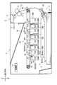
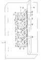
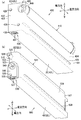
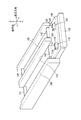
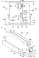
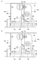
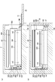
- FIG. 1 It is a figure which shows the schematic structure of the image forming apparatus which concerns on embodiment. It is the figure which looked at the inside of the main body housing with the cover open from the opening side. It is a perspective view (a) which shows a drum cartridge, and is a perspective view which shows a developing cartridge. It is a perspective view which shows the support plate. It is a side view (a) and the perspective view (b) which show the state of a drum cartridge and a developing cartridge when the cover of a main body housing is opened. It is a figure which shows the state (a) which the development cartridge is in a development contact position, and the state (b) which is in a development separation position after mounting the drum cartridge and the development cartridge in the main body housing. It is a figure which shows the process (a) of mounting a drum cartridge and a developing cartridge, and the state (b) which the cover of a main body housing is closed and mounting is completed.
- the image forming apparatus 1 is a color printer.
- the image forming apparatus 1 includes a main body housing 2, a supply unit 3, an image forming unit 4, a discharge roller 9, and a control unit 10.
- the supply unit 3 supplies the sheet S to the image forming unit 4.
- the image forming unit 4 forms an image on the sheet S.
- the discharge roller 9 discharges the sheet S.
- the main body housing 2 has a discharge unit 20 at the top.
- the sheet S is discharged to the discharge unit 20.
- the discharge unit 20 is located above the intermediate transfer belt 63, which will be described later.
- the supply unit 3 is located at the lower part in the main body housing 2.
- the supply unit 3 includes a supply tray 31 and a supply mechanism 32.
- the supply tray 31 is removable from the main body housing 2.
- the supply mechanism 32 conveys the sheet S from the supply tray 31 to the image forming unit 4.
- the image forming unit 4 includes a drum cartridge 400, a developing cartridge 500, an exposure apparatus SU, a transfer unit 60, and a fixing unit 70.
- the number of drum cartridges 400 and the number of developing cartridges 500 correspond to the number of toner colors, respectively. In this embodiment, four drum cartridges 400 and four developing cartridges 500 are arranged side by side.
- Each drum cartridge 400 has a photosensitive drum 410, a drum frame 420, a charger (not shown), and a first memory 430.
- the photosensitive drum 410 is rotatable about the first axis X1 extending in the axial direction.
- the direction parallel to the first axis X1 which is the rotation axis of the photosensitive drum 410 is simply referred to as "axial direction”.
- the four photosensitive drums 410 are arranged in orthogonal directions (simply referred to as "orthogonal directions” in the following description) that are orthogonal to the axial direction and the vertical direction.
- the drum frame 420 rotatably supports the photosensitive drum 410.
- the first memory 430 stores drum information which is information about the photosensitive drum 410.
- the drum information is, for example, information representing the cumulative rotation speed of the photosensitive drum 410.
- the drum cartridge 400 With the drum cartridge 400 and the developing cartridge 500 mounted on the main body housing 2, the drum cartridge 400 is lined up with the developing cartridge 500 along the orthogonal direction.
- Each developing cartridge 500 has a developing frame 520 for accommodating toners of different colors, a developing roller 510, and a second memory 530.
- the developing roller 510 is rotatable about a second axis X2 extending in the axial direction.
- the four developing rollers 510 are arranged in the orthogonal direction.
- the second memory 530 stores development information regarding at least one of the toner and the development roller 510.
- the development information is, for example, information representing the cumulative rotation speed of the development roller 510 and / or the remaining amount of toner contained in the development frame 520.
- the development information may include information indicating the amount of toner used in the development frame 520. For example, it is information indicating the printed dot count and the amount of toner used for printing.
- the exposure apparatus SU is located below each drum cartridge 400.
- the exposure apparatus SU emits laser light (see two-dot chain line) to each photosensitive drum 410.
- the transfer unit 60 is located between the four photosensitive drums 410 and the discharge unit 20.
- the transfer unit 60 includes a drive roller 61, a driven roller 62, an intermediate transfer belt 63, four primary transfer rollers 64, and a secondary transfer roller 65.
- the intermediate transfer belt 63 is an endless belt.
- the intermediate transfer belt 63 is located above the drum cartridge 400 and the developing cartridge 500 in a state where the drum cartridge 400 and the developing cartridge 500 are mounted on the main body housing 2.
- the surface of the photosensitive drum 410 comes into contact with the intermediate transfer belt 63 when the drum cartridge 400 and the developing cartridge 500 are mounted on the main body housing 2.
- the intermediate transfer belt 63 is stretched between the drive roller 61 and the driven roller 62.
- the primary transfer roller 64 is located inside the intermediate transfer belt 63.
- the primary transfer roller 64 sandwiches the intermediate transfer belt 63 with the photosensitive drum 410.
- the secondary transfer roller 65 is located outside the intermediate transfer belt 63.
- the secondary transfer roller 65 sandwiches the intermediate transfer belt 63 with the drive roller 61.
- the fixing unit 70 is located above the intermediate transfer belt 63.
- the fixing unit 70 includes a heating roller 71 and a pressurizing roller 72.
- the pressure roller 72 is pressed by the heating roller 71.
- the control unit 10 includes, for example, a CPU, a RAM, a ROM, and an input / output circuit, and controls printing by performing arithmetic processing based on information on a mounted cartridge, programs and data stored in the ROM, and the like. Execute.
- the image forming unit 4 first, the surface of the photosensitive drum 410 is charged by a charger. After that, the exposure apparatus SU exposes the surface of the photosensitive drum 410. As a result, an electrostatic latent image is formed on the photosensitive drum 410.
- the developing roller 510 supplies toner to the electrostatic latent image on the photosensitive drum 410. As a result, a toner image is formed on the photosensitive drum 410. Then, the toner image on the photosensitive drum 410 is transferred onto the intermediate transfer belt 63.
- the toner image on the intermediate transfer belt 63 is transferred onto the sheet S. After that, the toner image on the sheet S is fixed by the fixing unit 70. Next, the sheet S is discharged to the discharge unit 20 by the discharge roller 9.
- the main body housing 2 has an opening 21 and a cover 22.
- the opening 21 faces one side in the axial direction of the main body housing 2.
- the opening 21 allows the drum cartridge 400 and the developing cartridge 500 to be attached and detached in the axial direction.
- the drum cartridge 400 is axially removable with respect to the main body housing 2.
- the developing cartridge 500 can be attached to and detached from the main body housing 2 in the axial direction.
- the cover 22 can open and close the opening 21.
- main body housing 2 is configured to accommodate four drum cartridges 400 and four developing cartridges 500 at predetermined positions, respectively. Inside the main body housing 2, nine guide walls 150 that partition the storage spaces of the drum cartridge 400 and the developing cartridge 500 are fixed.
- the guide wall 150 is a striking partition wall that projects upward from the vicinity of the lower edge of the opening 21 and extends the inside of the main body housing 2 to the back side in the axial direction, and defines a boundary in the orthogonal direction of each cartridge accommodating space.
- the guide wall 150 functions as a guide rail for guiding each cartridge.
- the main body housing 2 has a first terminal 110, a first connecting plate 112, two first positioning protrusions 113, and a drum drive connecting portion 115 in the accommodation space of each drum cartridge 400, respectively. ..
- the two first positioning protrusions 113 are fixed at predetermined positions of the first connecting plate 112, respectively.
- the first connecting plate 112 and the drum drive connecting portion 115 are located along a vertical wall on the back side away from the opening 21 in the main body housing 2. The first connecting plate 112 and the drum drive connecting portion 115 can be moved in the vertical direction.
- the main body housing 2 has a second terminal 120, a second connecting plate 122, two second positioning protrusions 123, and a developing drive connecting portion 125 in the accommodation space of each developing cartridge 500, respectively. ing.
- the two second positioning protrusions 123 are fixed at predetermined positions of the second connecting plate 122, respectively.
- the second connecting plate 122 and the developing drive connecting portion 125 are located along a vertical wall on the back side away from the opening 21 in the main body housing 2.
- the second connecting plate 122 and the development driving connecting portion 125 can be moved in the vertical direction and the orthogonal direction.
- the support plate 140 Under the storage space of the four sets of corresponding drum cartridges 400 and the developing cartridge 500, the support plate 140 is located with one guide wall 150 partitioning between the two cartridge storage spaces, respectively. There is.
- the support plate 140 extends in parallel in the axial direction and the orthogonal direction from the vicinity of the lower edge of the opening 21 toward the back side.
- the first terminal 110 and the second terminal 120 are located on the support plate 140.
- the first terminal 110 corresponds to each drum cartridge 400.
- the second terminal 120 corresponds to each developing cartridge 500.
- Each first terminal 110 and each second terminal 120 are connected to the control unit 10 via a support plate 140.
- the first terminal 110 has a first terminal contact 11C and an engaging recess 11R.
- the second terminal 120 has a second terminal contact 12C and an engaging recess 12R.
- the configuration and position of the drum frame 420 of the drum cartridge 400 and the configuration and position of the first memory 430 will be described in detail with reference to FIG. 3A.
- the drum frame 420 has a first end portion 1E on which the photosensitive drum 410 is located and a second end portion located away from the first end portion 1E in the vertical direction with the drum cartridge 400 mounted on the main body housing 2. Has 2E.
- the drum frame 420 is a hexahedron long in the axial direction, and has a drum upper end surface 42U, a drum lower end surface 42L, a first drum outer surface 421, a second drum outer surface 422, a third drum outer surface 423, and a third drum frame 420. It has 4 drum outer surfaces 424.
- the drum upper end surface 42U is located at the first end portion 1E.
- the lower end surface 42L of the drum is located at the second end 2E.
- the first drum outer surface 421, the second drum outer surface 422, the third drum outer surface 423, and the fourth drum outer surface 424 are outer surfaces connecting the drum upper end surface 42U and the drum lower end surface 42L.
- the outer surface 421 of the first drum and the outer surface 422 of the second drum are located apart from each other in the axial direction.
- the third drum outer surface 423 and the fourth drum outer surface 424 are located apart from each other in the orthogonal direction.
- the second drum outer surface 422 is an outer surface located farther from the opening 21 than the first drum outer surface 421 in the axial direction with the drum cartridge 400 mounted on the main body housing.
- the third drum outer surface 423 provides a developing roller 510 with which the photosensitive drum 410 comes into contact with the fourth drum outer surface 424 in the orthogonal direction with the drum cartridge 400 and the developing cartridge 500 mounted on the main body housing 2.
- An outer surface located away from the corresponding developing cartridge 500 having.
- the drum cartridge 400 has a drum coupling 440 and two first positioning holes 426 on the outer surface 422 of the second drum.
- the drum coupling 440 is connected to the drum drive connecting portion 115 (see FIG. 2) of the main body housing 2 with the drum cartridge 400 mounted on the main body housing 2, and provides a driving force for rotationally driving the photosensitive drum 410. input.
- the two first positioning holes 426 are fitted with the first positioning protrusions 113 (see FIG. 2) fixed to the first connecting plate 112 of the main body housing 2 with the drum cartridge 400 mounted on the main body housing 2. ..
- the first memory 430 is located at the second end 2E of the drum frame 420.
- the photosensitive drum 410 is located between the intermediate transfer belt 63 and the first memory 430 in the vertical direction (see FIG. 1).
- the first memory 430 is located.
- the first memory 430 is located on the lower end surface of the drum 42L.
- the shape of the second end portion 2E is not limited to the shape shown in the figure, and various other forms can be assumed. Therefore, it is understood that the first memory 430 may be located at a convex portion or a concave portion deviating from the drum lower end surface 42L at the second end portion 2E.
- the first memory 430 is closer to the second drum outer surface 422 than the first drum outer surface 421 at the second end 2E of the drum frame 420, that is, the drum cartridge 400 is mounted on the main body housing 2. In the state, it is located on the back side away from the opening 21.
- the first memory 430 has two first contacts 431 and two engaging protrusions 435.
- the engaging projection 435 engages with the engaging recess 11R of the first terminal 110 and is positioned with respect to the first terminal 110, and the first contact 431 is the first. It contacts the terminal 110 (specifically, the first terminal contact 11C) and is electrically connected.
- the photosensitive drum 410 is exposed from the upper opening of the drum upper end surface 42U of the drum frame 420 and the second drum outer surface 422, and the intermediate transfer belt 63 and the corresponding developing roller 510.
- An axially long rib 428 is located on the outer surface 421 of the first drum of the drum frame 420.
- ribs 428 long in the axial direction are located on the outer surface 423 of the third drum of the drum frame 420 (see FIGS. 5A and 5B). The rib 428 will be described later.
- the developing frame 520 has a third end 3E on which the developing roller 510 is located and a fourth end located away from the third end 3E in the vertical direction with the developing cartridge 500 mounted on the main body housing 2. Has 4E.
- the development frame 520 is a hexahedron long in the axial direction, and has a development upper end surface 52U, a development lower end surface 52L, a first development outer surface 521, a second development outer surface 522, a third development outer surface 523, and a third. It has 4 developed outer surfaces 524.
- the development upper end surface 52U is located at the third end portion 3E.
- the development lower end surface 52L is located at the fourth end portion 4E.
- the first developed outer surface 521, the second developed outer surface 522, the third developed outer surface 523, and the fourth developed outer surface 524 are outer surfaces connecting the developed upper end surface 52U and the developed lower end surface 52L.
- the first developed outer surface 521 and the second developed outer surface 522 are located apart from each other in the axial direction.
- the third developed outer surface 523 and the fourth developed outer surface 524 are located apart from each other in the orthogonal direction.
- the second developed outer surface 522 is an outer surface located farther from the opening 21 than the first developed outer surface 521 in the axial direction in a state where the developing cartridge 500 is mounted on the main body housing 2.
- the third developing outer surface 523 is a photosensitive drum 410 that the developing roller 510 contacts with the developing outer surface 524 in the orthogonal direction with the drum cartridge 400 and the developing cartridge 500 mounted on the main body housing 2.
- An outer surface located near the corresponding drum cartridge 400 having.
- the development cartridge 500 has a positioning boss 525, a development coupling 540, and a development coupling cover 545 on the second development outer surface 522.
- the development coupling 540 is connected to the development drive connecting portion 125 (see FIG. 2) of the main body housing 2 with the development cartridge 500 mounted on the main body housing 2, and provides a driving force for rotationally driving the development roller 510. input.
- the development coupling cover 545 covers the outer circumference of the development coupling 540.
- a second positioning hole 526 is located in each of the positioning boss 525 and the developing coupling cover 545. The two second positioning holes 526 are fitted with the second positioning protrusion 123 (see FIG. 2) fixed to the second connecting plate 122 of the main body housing 2 with the developing cartridge 500 mounted on the main body housing 2. ..
- the second memory 530 is located at the fourth end 4E of the developing frame 520.
- the developing roller 510 is located between the intermediate transfer belt 63 and the second memory 530 in the vertical direction (see FIG. 1).
- the second memory 530 is located.
- the second memory 530 is located on the development lower end surface 52L.
- the shape of the fourth end portion 4E is not limited to the shape shown in the figure, and various other forms can be assumed. Therefore, it is understood that the second memory 530 may be located at a convex portion or a concave portion deviating from the development lower end surface 52L at the fourth end portion 4E.
- the second memory 530 is closer to the second development outer surface 522 than the first development outer surface 521 at the fourth end 4E of the development frame 520, that is, the development cartridge 500 is mounted on the main body housing 2. In the state, it is located on the back side away from the opening 21. In the present embodiment, the second memory 530 is located on the lower end surface of the development coupling cover 545.
- the second memory 530 has two second contacts 531 and two engaging protrusions 535.
- the engaging protrusion 535 engages with the engaging recess 12R of the second terminal 120 and is positioned with respect to the second terminal 120, and the second contact 531 is second. It contacts the terminal 120 (specifically, the second terminal contact 12C) and is electrically connected.
- the developing roller 510 is exposed from the upper opening of the third developing outer surface 523 of the drum frame and is located so as to be in contact with the corresponding photosensitive drum 410.
- An axially long rib 528 is located on the outer surface 424 of the fourth drum of the developing frame 520.
- a rib 528 that is long in the axial direction is located on the outer surface 423 of the third drum of the drum frame 420 (see FIG. 5A).
- the support plate 140 is slidable in the axial direction with respect to the lift plate 130.
- the support plate 140 has an opening 145 in the center.
- a guide wall 150 penetrates into the opening 145.
- the lift plate 130 and the support plate 140 are restricted from moving in the orthogonal direction by guide walls 150 located in the openings 145 on both sides and in the center in the orthogonal direction.
- Axial movement of the support plate 140 is also restricted by a guide wall 150 that penetrates the central opening.
- the central opening of the lift plate 130 (not shown) has a larger axial dimension than the central guide wall 150, and can move in the axial direction to the extent that rotation by the four-node link mechanism described later is allowed.
- the lift plate 130 can be moved up and down.
- the drum support plate 116 and the development support plate 126 are configured to be raised and lowered at the same time by moving the lift plate 130 up and down.
- the lift plate 130 has a plurality of openings (not shown), and is configured so that the laser beam emitted from the exposure apparatus SU can expose the photosensitive drum 410 of the mounted drum cartridge 400 through each opening. There is.
- the support plate 140 has two first support blocks 141 located axially apart from each other on the opening 21 side (see FIG. 2) in the axial direction with respect to the first terminal 110.
- the support plate 140 has two second support blocks 142 located axially apart from each other on the opening 21 side (see FIG. 2) in the axial direction with respect to the second terminal 120.
- the support plate 140 is located below the drum cartridge 400 with the drum cartridge 400 mounted on the main body housing 2, and the drum cartridge 400 is supported from below by the first support block 141. Further, the support plate 140 is located below the development cartridge 500 with the development cartridge 500 mounted on the main body housing 2, and the development cartridge 500 is supported from below by the second support block 142.
- the first support block 141 and the second support block 142 have substantially the same height dimensions as the first terminal 110 and the second terminal 120, respectively.
- the first terminal 110 can be electrically contacted with the first contact 431 (see FIG. 3A) of the first memory 430 of the drum cartridge 400.
- the information stored in the first memory 430 is sent to the control unit 10 via the first terminal 110.
- the second terminal 120 is electrically contactable with the second contact 531 (see FIG. 3B) of the second memory 530 of the developing cartridge 500.
- the information stored in the second memory 530 is sent to the control unit 10 via the second terminal 120.
- the support plate 140 can be moved in the vertical direction between a drum separation position where the photosensitive drum 410 is separated from the intermediate transfer belt 63 and a drum contact position where the photosensitive drum 410 is brought into contact with the intermediate transfer belt 63.
- the drum cartridge 400 is supported by the guide wall 150 at the rib 428, and the first memory 430 is separated from the first terminal 110.
- the photosensitive drum 410 is separated from the intermediate transfer belt 63.
- the developing cartridge 500 is supported by the guide wall 150 at the rib 528, and the second memory 530 is separated from the second terminal 120.
- the drum cartridge When the support plate 140 is in the drum contact position shown in FIG. 6A, the drum cartridge is supported by the first support block 141 (see FIG. 4) of the support plate 140, and the first memory 430 is the first terminal 110.
- the photosensitive drum 410 is in contact with the intermediate transfer belt 63.
- the developing cartridge 500 is supported by the second support block 142 (see FIG. 4) of the support plate 140, and the second memory 530 is in contact with the second terminal 120.
- the developing cartridge 500 slides on the second support block 142 in the orthogonal direction by a developing separation mechanism (not shown), so that the developing contact position where the developing roller 510 contacts the photosensitive drum 410 (FIG. 6A). (See) and the developing separation position (see FIG. 6B) at which the developing roller 510 is separated from the photosensitive drum 410).
- the second terminal 120 is attached so as to be movable in the direction orthogonal to the support plate 140. Therefore, when the development cartridge 500 mounted on the main body housing 2 moves between the development separation position and the development contact position, the second terminal 120 slides and moves following the movement of the development cartridge 500. The contact of the second contact 531 with the second terminal 120 can be maintained.
- the movement of the support plate 140 between the drum separation position and the drum contact position is linked with the opening / closing operation of the cover 22 of the main body housing 2.
- an inner cover 23 that rotates integrally with the cover 22 is located inside the cover 22 of the main body housing 2.
- the lift plate 130 is located inside the main body housing 2.
- the support plate 140 is located above the lift plate 130.
- the ends on the opening 21 side and the back side in the axial direction are connected to the main body housing 2 by the first link 27 and the second link 28, respectively, to form a four-bar link mechanism. are doing.
- the first link 27 is fixed to the inner cover 23. Therefore, when the cover 22 is rotated from the open position to the closed position, the inner cover 23 and the first link 27 rotate integrally, and the lift plate 130 is moved together with the driven second link 28 in FIG. 7 (b). ) To the position shown. At this time, the support plate 140 on the lift plate 130 rises to the drum contact position shown in FIG. 6A.
- the drum cartridge 400 and the developing cartridge 500 are mounted on the main body housing 2, and as shown in FIG. 6A, the first memory 430 is the first terminal.
- the second memory 530 comes into contact with the second terminal 120. Further, at this time, the photosensitive drum 410 comes into contact with the intermediate transfer belt 63.
- FIGS. 6 (a) and 7 (b) The state in which the drum cartridge 400 and the developing cartridge 500 are mounted is shown in FIGS. 6 (a) and 7 (b). At this time, the support plate 140 is located at the drum contact position.
- the lift plate 130 is lowered and the support plate 140 is moved downward as shown in FIG. Then, the drum cartridge 400 and the developing cartridge 500 are lowered, the rib 428 and the rib 528 are brought into contact with the upper end of the guide wall 150, and the drum cartridge 400 and the developing cartridge 500 are supported on the guide wall 150.
- the support plate 140 is located at the drum contact position (see FIGS. 5A and 5B).
- the first connecting plate 112 and the drum drive connecting portion 115 move downward together with the drum cartridge 400, and the second connecting plate 122 and the developing driving connecting portion 125 move downward together with the developing cartridge 500. Therefore, the connection of the drum coupling 440 with the drum drive connection portion 115 and the connection of the development coupling 540 with the development drive connection portion 125 are maintained.
- the drum coupling 440 is connected to the drum drive connecting portion 115, and the developing coupling 540 is connected to the developing driving connecting portion 125.
- the drum cartridge 400 and / or the developing cartridge 500 can be taken out through the opening 21 while breaking the connection with the ribs 480 and 580 and sliding the ribs 480 and 580 along the guide wall 150.
- the drum cartridge 400 When the drum cartridge 400 is mounted on the main body housing 2, first, the ribs 428 of the third drum outer surface 423 and the fourth drum outer surface 424 guide the corresponding main body housing 2 from the second drum outer surface 422 side. It is located on the wall 150 and is pushed into the main body housing 2 along the guide wall 150 as shown in FIG. 7A. Then, the drum coupling 440 is positioned in a state of being connected to the drum drive connecting portion 115 (see FIG. 2). In this process, as shown in FIG. 5A, since the support plate 140 is in the drum separation position, the photosensitive drum 410 and the drum frame 420 are separated from the intermediate transfer belt 63, and the first memory 430 is in the first memory 430. Does not come into contact with 1 terminal 110
- the ribs 528 of the third developed outer surface 523 and the fourth developed outer surface 524 guide the corresponding main body housing 2 from the second developed outer surface 522 side.
- the drum coupling 440 is drum-driven connecting 115 (see FIG. 2). ) Is connected and positioned.
- FIG. 5A since the support plate 140 is in the drum separation position, the developing frame 520 is separated from the intermediate transfer belt 63, and the second memory 530 is connected to the second terminal 120. There is no contact.
- the first memory 430 is located at the second end 2E of the drum frame 420, the back end surface (second drum) of the drum cartridge 400 in the axial direction where the drum coupling 440 and the first positioning hole 426 are located.
- the contact area of the first contact 431 can be sufficiently secured without being restricted by the space on the outer surface 422).
- the second memory 530 is located at the fourth end 4E of the developing frame 520, the development cartridge 500 is located at the back in the axial direction where the developing coupling 540, the positioning boss 525, and the second positioning hole 526 are located.
- the contact area of the second contact 531 can be sufficiently secured without being restricted by the space on the side end surface (second developed outer surface 522).
- the first memory 430 is located closer to the second drum outer surface 422 than the first drum outer surface 421, that is, at a position away from the opening 21, when the drum cartridge 400 is attached to or detached from the main body housing 2. In such a case, it is possible to prevent the user from accidentally touching the first terminal 110 on the main body housing 2 side. Further, it is possible to prevent the first terminal 110 from coming into contact with the drum frame 420 (and by extension, wear and damage associated therewith).
- the second memory 530 is also located closer to the second development outer surface 522 than the first development outer surface 521, that is, at a position away from the opening 21, when the development cartridge 500 is attached to or detached from the main body housing 2. In such a case, it is possible to prevent the user from accidentally touching the second terminal 120 on the main body housing 2 side. Further, it is possible to prevent the second terminal 120 from coming into contact with the developing frame 520 (and by extension, wear and damage associated therewith).
- the support plate 140 When the support plate 140 is in the drum contact position, the first terminal 110 is separated from the first contact 431, the second terminal 120 is separated from the second contact 531, and the support plate 140 is in the drum contact position. Since the terminal 110 is configured to contact the first contact 431 and the second terminal 120 to contact the second contact 531, the contact separation operation of the photosensitive drum 410 with respect to the intermediate transfer belt 63 and the memory (first memory).
- the connection or disconnection of the housing side terminals (first terminal 110, second terminal 120) of the 430 and the second memory 530) can be linked with each other.
- the main body housing 2 illustrates a configuration in which the four drum cartridges 400 and the four developing cartridges 500 are detachable through one opening 21, but the main body housing is the corresponding drum.
- Each set of the cartridge 400 and the developing cartridge 500 may have one opening. That is, the main body housing may have four openings.
- the main body housing may have one first opening corresponding to one drum cartridge 400 and one second opening corresponding to one developing cartridge 500.
- the main body housing may have one cover for each set of the corresponding drum cartridge 400 and the developing cartridge 500. That is, the main body housing may have four covers.
- the main body housing may have one first cover corresponding to one first opening and one second cover corresponding to one second opening. That is, the main body housing may have four first covers and four second covers.
- the embodiment in which the drum cartridge 400 and the developing cartridge 500 are moved up and down in conjunction with the opening and closing of the cover 22 is illustrated, but the movement of the support plate 140 to the drum contact position and the drum separation position is not performed. It may be possible to perform it independently of opening and closing the cover.
- the support plate 140 illustrates the configuration in which the drum cartridge 400 and the developing cartridge 500 are supported below the drum cartridge 400 and the developing cartridge 500
- the drum located below the drum cartridge and supporting the drum cartridge is supported. It may have a support plate and a development support plate located below the development cartridge to support the development cartridge.
- the development support plate does not have to be movable with the vertical movement of the drum support plate.
- the contact separation operation of the photosensitive drum with respect to the intermediate transfer belt and the connection with the first terminal of the first memory are performed as in the above-described embodiment.
- the switching of disconnection and the switching of connection / disconnection with the second terminal on the housing side of the second memory can be linked.
- the first memory 430 is located at the second end 2E (specifically, the lower end surface of the drum 42L), and the second memory 530 is located at the fourth end 4E (specifically, the lower end surface of the development).
- the case of being located at 52L) has been illustrated, it may be configured so that only one of the first memory and the second memory is located at the lower end of the corresponding drum cartridge 400 or the lower end of the developing cartridge 500.
- the position of the first memory 430 at the lower end of each drum cartridge 400 is not limited to the illustrated position, and may be a position close to the opening, and if it is below the first axis of the photosensitive drum, the drum cartridge It is also possible to select a position closer to the intermediate transfer belt than the lower end surface of the 400.
- the position of the second memory 530 at the lower end of the developing cartridge 500 is not limited to the illustrated position, and may be a position close to the opening, and if it is below the second axis of the developing roller, the developing cartridge 500 It is also possible to select a position closer to the intermediate transfer belt than the lower end surface of.
- the second memory 530 is located on the lower end surface of the developing coupling cover 545, but may be located closer to the opening than the developing coupling cover.
- the "orthogonal direction" exemplifies the directions orthogonal to the axial direction and the vertical direction, but the orthogonal direction may be a direction orthogonal to the axial direction and not orthogonal to the vertical direction.
- the image forming apparatus 1 is a color printer, but other image forming apparatus, for example, a monochrome printer, a copying machine, a multifunction device, or the like may be used.
Landscapes
- Physics & Mathematics (AREA)
- General Physics & Mathematics (AREA)
- Engineering & Computer Science (AREA)
- Computer Vision & Pattern Recognition (AREA)
- Computer Networks & Wireless Communication (AREA)
- Electrophotography Configuration And Component (AREA)
- Dry Development In Electrophotography (AREA)
Applications Claiming Priority (2)
| Application Number | Priority Date | Filing Date | Title |
|---|---|---|---|
| JP2019065282A JP7014202B2 (ja) | 2019-03-29 | 2019-03-29 | 画像形成装置 |
| JP2019-065282 | 2019-03-29 |
Publications (1)
| Publication Number | Publication Date |
|---|---|
| WO2020202589A1 true WO2020202589A1 (ja) | 2020-10-08 |
Family
ID=72605867
Family Applications (1)
| Application Number | Title | Priority Date | Filing Date |
|---|---|---|---|
| PCT/JP2019/022115 Ceased WO2020202589A1 (ja) | 2019-03-29 | 2019-06-04 | 画像形成装置 |
Country Status (3)
| Country | Link |
|---|---|
| US (4) | US10935925B2 (enExample) |
| JP (1) | JP7014202B2 (enExample) |
| WO (1) | WO2020202589A1 (enExample) |
Families Citing this family (8)
| Publication number | Priority date | Publication date | Assignee | Title |
|---|---|---|---|---|
| US9996052B2 (en) * | 2016-02-10 | 2018-06-12 | Canon Kabushiki Kaisha | Cartridge capable of being inserted in an apparatus main body of an image forming apparatus |
| JP7014202B2 (ja) | 2019-03-29 | 2022-02-01 | ブラザー工業株式会社 | 画像形成装置 |
| JP7472442B2 (ja) | 2019-08-30 | 2024-04-23 | ブラザー工業株式会社 | ドラムカートリッジ及び画像形成装置 |
| JP2021039173A (ja) * | 2019-08-30 | 2021-03-11 | ブラザー工業株式会社 | ドラムカートリッジ |
| JP7635598B2 (ja) | 2021-03-29 | 2025-02-26 | 富士フイルムビジネスイノベーション株式会社 | 画像形成装置 |
| JP7647380B2 (ja) * | 2021-06-22 | 2025-03-18 | 京セラドキュメントソリューションズ株式会社 | 画像形成装置 |
| JP7721983B2 (ja) * | 2021-06-24 | 2025-08-13 | ブラザー工業株式会社 | プロセスカートリッジ |
| JP2023003445A (ja) | 2021-06-24 | 2023-01-17 | ブラザー工業株式会社 | ドラムカートリッジおよびプロセスカートリッジ |
Citations (6)
| Publication number | Priority date | Publication date | Assignee | Title |
|---|---|---|---|---|
| JP2001092225A (ja) * | 1999-09-22 | 2001-04-06 | Canon Inc | プロセスカートリッジ及び現像カートリッジ及び電子写真画像形成装置 |
| JP2006119553A (ja) * | 2004-10-25 | 2006-05-11 | Ricoh Co Ltd | 画像形成ユニットおよび画像形成装置 |
| JP2007052056A (ja) * | 2005-08-15 | 2007-03-01 | Seiko Epson Corp | 画像形成装置、及び、画像形成システム |
| JP2007171799A (ja) * | 2005-12-26 | 2007-07-05 | Fuji Xerox Co Ltd | 画像形成装置、像形成ユニット、像形成ユニットの交換方向、及び像形成ユニットの製造方法 |
| JP2014119505A (ja) * | 2012-12-13 | 2014-06-30 | Canon Inc | 画像形成装置 |
| JP2018173480A (ja) * | 2017-03-31 | 2018-11-08 | ブラザー工業株式会社 | 現像カートリッジ、プロセスカートリッジ、および画像形成装置 |
Family Cites Families (22)
| Publication number | Priority date | Publication date | Assignee | Title |
|---|---|---|---|---|
| JPH04331959A (ja) | 1991-05-07 | 1992-11-19 | Ricoh Co Ltd | 画像形成装置用コネクタ |
| JP2000075767A (ja) | 1998-08-31 | 2000-03-14 | Canon Inc | プロセスカートリッジ及び電子写真画像形成装置 |
| JP3970279B2 (ja) * | 2004-07-30 | 2007-09-05 | キヤノン株式会社 | プロセスカートリッジ及び電子写真画像形成装置 |
| WO2006062026A1 (ja) * | 2004-12-09 | 2006-06-15 | Seiko Epson Corporation | 現像装置、画像形成装置、画像形成システム、カートリッジ、現像ユニット、及び、感光体ユニット |
| US8050597B2 (en) | 2006-11-09 | 2011-11-01 | Ricoh Company, Limited | Toner container having a gear portion and image forming apparatus |
| JP4803828B2 (ja) | 2006-11-09 | 2011-10-26 | 株式会社リコー | トナー容器、プロセスカートリッジ、及び、画像形成装置 |
| KR101720530B1 (ko) | 2010-12-09 | 2017-03-28 | 에스프린팅솔루션 주식회사 | 화상형성장치 |
| JP2014119516A (ja) | 2012-12-13 | 2014-06-30 | Ricoh Co Ltd | 駆動ユニット及び画像形成装置 |
| JP6590534B2 (ja) | 2015-05-29 | 2019-10-16 | キヤノン株式会社 | プロセスカートリッジ及び画像形成装置 |
| JP6555967B2 (ja) * | 2015-07-31 | 2019-08-07 | キヤノン株式会社 | 画像形成装置 |
| JP2017090692A (ja) | 2015-11-11 | 2017-05-25 | 京セラドキュメントソリューションズ株式会社 | 画像形成装置 |
| US9996052B2 (en) * | 2016-02-10 | 2018-06-12 | Canon Kabushiki Kaisha | Cartridge capable of being inserted in an apparatus main body of an image forming apparatus |
| JP6465906B2 (ja) | 2016-02-29 | 2019-02-06 | キヤノン株式会社 | 現像装置、プロセスカートリッジおよび画像形成装置 |
| US10156825B2 (en) | 2016-02-29 | 2018-12-18 | Canon Kabushiki Kaisha | Developing apparatus with independently rotatable members supporting a developing frame body, process cartridge, and image forming apparatus |
| JP2017156441A (ja) * | 2016-02-29 | 2017-09-07 | ブラザー工業株式会社 | 画像形成装置 |
| JP6849396B2 (ja) | 2016-11-01 | 2021-03-24 | キヤノン株式会社 | 画像形成装置 |
| JP6938984B2 (ja) | 2017-03-15 | 2021-09-22 | 富士フイルムビジネスイノベーション株式会社 | 端子の接触構造及び画像形成装置 |
| JP2018173526A (ja) | 2017-03-31 | 2018-11-08 | ブラザー工業株式会社 | 画像形成装置およびカートリッジ |
| JP2018205537A (ja) | 2017-06-05 | 2018-12-27 | キヤノン株式会社 | カートリッジ |
| JP6900250B2 (ja) * | 2017-06-16 | 2021-07-07 | キヤノン株式会社 | 光プリントヘッドを備える画像形成装置 |
| JP7098339B2 (ja) | 2018-01-24 | 2022-07-11 | キヤノン株式会社 | 画像形成装置 |
| JP7014202B2 (ja) * | 2019-03-29 | 2022-02-01 | ブラザー工業株式会社 | 画像形成装置 |
-
2019
- 2019-03-29 JP JP2019065282A patent/JP7014202B2/ja active Active
- 2019-06-04 WO PCT/JP2019/022115 patent/WO2020202589A1/ja not_active Ceased
-
2020
- 2020-02-12 US US16/788,878 patent/US10935925B2/en active Active
-
2021
- 2021-02-16 US US17/176,259 patent/US11294325B2/en active Active
-
2022
- 2022-03-04 US US17/686,582 patent/US11853000B2/en active Active
-
2023
- 2023-11-06 US US18/502,208 patent/US12242220B2/en active Active
Patent Citations (6)
| Publication number | Priority date | Publication date | Assignee | Title |
|---|---|---|---|---|
| JP2001092225A (ja) * | 1999-09-22 | 2001-04-06 | Canon Inc | プロセスカートリッジ及び現像カートリッジ及び電子写真画像形成装置 |
| JP2006119553A (ja) * | 2004-10-25 | 2006-05-11 | Ricoh Co Ltd | 画像形成ユニットおよび画像形成装置 |
| JP2007052056A (ja) * | 2005-08-15 | 2007-03-01 | Seiko Epson Corp | 画像形成装置、及び、画像形成システム |
| JP2007171799A (ja) * | 2005-12-26 | 2007-07-05 | Fuji Xerox Co Ltd | 画像形成装置、像形成ユニット、像形成ユニットの交換方向、及び像形成ユニットの製造方法 |
| JP2014119505A (ja) * | 2012-12-13 | 2014-06-30 | Canon Inc | 画像形成装置 |
| JP2018173480A (ja) * | 2017-03-31 | 2018-11-08 | ブラザー工業株式会社 | 現像カートリッジ、プロセスカートリッジ、および画像形成装置 |
Also Published As
| Publication number | Publication date |
|---|---|
| US11853000B2 (en) | 2023-12-26 |
| US20210165360A1 (en) | 2021-06-03 |
| JP2020166090A (ja) | 2020-10-08 |
| US20220187756A1 (en) | 2022-06-16 |
| US20200310339A1 (en) | 2020-10-01 |
| US12242220B2 (en) | 2025-03-04 |
| US20240142911A1 (en) | 2024-05-02 |
| US11294325B2 (en) | 2022-04-05 |
| JP7014202B2 (ja) | 2022-02-01 |
| US10935925B2 (en) | 2021-03-02 |
Similar Documents
| Publication | Publication Date | Title |
|---|---|---|
| JP7014202B2 (ja) | 画像形成装置 | |
| JP5137647B2 (ja) | 画像形成装置 | |
| KR100894955B1 (ko) | 전자사진 컬러 화상 형성 장치 | |
| US8213830B2 (en) | Image forming apparatus in which developer carrying members can be separated from photosensitive members | |
| JP7639875B2 (ja) | 画像形成装置 | |
| JP2010107679A (ja) | 給電機構および画像形成装置 | |
| WO2020070920A1 (ja) | 画像形成装置 | |
| US11347176B2 (en) | Image forming apparatus | |
| JP7334807B2 (ja) | 画像形成装置 | |
| JP2020166089A (ja) | 画像形成装置 | |
| JP6645602B1 (ja) | 画像形成装置 | |
| JP7528568B2 (ja) | 画像形成装置 | |
| JP7230796B2 (ja) | 画像形成装置 | |
| JP7571831B2 (ja) | 画像形成装置 | |
| JP3166408U (ja) | 画像形成装置およびプロセスカートリッジ | |
| JP2020148881A (ja) | 画像形成装置 | |
| JP2025077581A (ja) | 画像形成装置 | |
| US20060078350A1 (en) | Color image forming apparatus | |
| JP2001066971A (ja) | 画像形成装置 | |
| JP2011180508A (ja) | 画像形成装置 |
Legal Events
| Date | Code | Title | Description |
|---|---|---|---|
| 121 | Ep: the epo has been informed by wipo that ep was designated in this application |
Ref document number: 19923589 Country of ref document: EP Kind code of ref document: A1 |
|
| NENP | Non-entry into the national phase |
Ref country code: DE |
|
| 122 | Ep: pct application non-entry in european phase |
Ref document number: 19923589 Country of ref document: EP Kind code of ref document: A1 |