WO2020195049A1 - Ni基超耐熱合金の製造方法およびNi基超耐熱合金 - Google Patents
Ni基超耐熱合金の製造方法およびNi基超耐熱合金 Download PDFInfo
- Publication number
- WO2020195049A1 WO2020195049A1 PCT/JP2020/001725 JP2020001725W WO2020195049A1 WO 2020195049 A1 WO2020195049 A1 WO 2020195049A1 JP 2020001725 W JP2020001725 W JP 2020001725W WO 2020195049 A1 WO2020195049 A1 WO 2020195049A1
- Authority
- WO
- WIPO (PCT)
- Prior art keywords
- resistant alloy
- heat
- less
- heat treatment
- plastic working
- Prior art date
- Legal status (The legal status is an assumption and is not a legal conclusion. Google has not performed a legal analysis and makes no representation as to the accuracy of the status listed.)
- Ceased
Links
Images


Classifications
-
- C—CHEMISTRY; METALLURGY
- C22—METALLURGY; FERROUS OR NON-FERROUS ALLOYS; TREATMENT OF ALLOYS OR NON-FERROUS METALS
- C22C—ALLOYS
- C22C19/00—Alloys based on nickel or cobalt
- C22C19/03—Alloys based on nickel or cobalt based on nickel
- C22C19/05—Alloys based on nickel or cobalt based on nickel with chromium
-
- C—CHEMISTRY; METALLURGY
- C22—METALLURGY; FERROUS OR NON-FERROUS ALLOYS; TREATMENT OF ALLOYS OR NON-FERROUS METALS
- C22F—CHANGING THE PHYSICAL STRUCTURE OF NON-FERROUS METALS AND NON-FERROUS ALLOYS
- C22F1/00—Changing the physical structure of non-ferrous metals or alloys by heat treatment or by hot or cold working
- C22F1/10—Changing the physical structure of non-ferrous metals or alloys by heat treatment or by hot or cold working of nickel or cobalt or alloys based thereon
-
- C—CHEMISTRY; METALLURGY
- C22—METALLURGY; FERROUS OR NON-FERROUS ALLOYS; TREATMENT OF ALLOYS OR NON-FERROUS METALS
- C22F—CHANGING THE PHYSICAL STRUCTURE OF NON-FERROUS METALS AND NON-FERROUS ALLOYS
- C22F1/00—Changing the physical structure of non-ferrous metals or alloys by heat treatment or by hot or cold working
Definitions
- the present invention relates to a method for producing a Ni-based superheat-resistant alloy and, specifically, a Ni-based superheated alloy having a component composition in which the equilibrium precipitation amount of the gamma prime phase at 700 ° C. is 35 mol% or more. It relates to a method for producing a heat-resistant alloy and a Ni-based super heat-resistant alloy.
- Ni-based super heat-resistant alloys such as Inconel (registered trademark) 718 alloy are often used.
- heat-resistant parts having a high heat-resistant temperature are required.
- the gamma prime (hereinafter, also referred to as “ ⁇ '”) phase which is a precipitation strengthening phase of an intermetallic compound having Ni 3 Al as a main composition. It is most effective to increase the amount of.
- the Ni-based superheat-resistant alloy further contains the ⁇ 'forming elements Al, Ti, and Nb, so that the high-temperature strength of the Ni-based superheat-resistant alloy can be further improved.
- a Ni-based super heat resistant alloy having a larger amount of ⁇ 'phase will be required.
- Ni-based superheat-resistant alloys are difficult to process because the deformation resistance of hot processing increases as the ⁇ 'phase increases.
- the amount of the ⁇ 'phase is 35 to 40 mol% or more, the processability is particularly lowered.
- alloys such as Inconel (registered trademark) 713C alloy, IN939, IN100, and Mar-M247 have a particularly large number of ⁇ 'phases, which makes plastic working impossible, and are usually cast as cast alloys (as-cast). Used in.
- Patent Document 1 As a proposal for improving the hot plastic workability of such a Ni-based superheat-resistant alloy, in Patent Document 1, a Ni-based superheat-resistant alloy ingot having a composition having a ⁇ 'molar ratio of 40 mol% or more is processed at a processing rate of 5%. A manufacturing method is described in which cold working is performed at a temperature of less than 30% and then heat treatment is performed at a temperature exceeding the ⁇ 'solid solution temperature. In this method, a recrystallization rate of 90% or more, which enables hot working to be applied to a Ni-based superheat-resistant alloy, is obtained by combining a cold working step and a heat treatment step.
- Ni-based superheat-resistant alloy having a large amount of ⁇ 'phase
- a fine wire of Ni-based super heat-resistant alloy is required as a modeling material in that case.
- This thin wire can also be used by processing it into a component shape such as a spring.
- the wire diameter (diameter) of the thin wire of the Ni-based superheat-resistant alloy is, for example, as thin as 5 mm or less and further 3 mm or less.
- a thin wire for example, it is efficient to prepare a "wire rod" having a wire diameter of 10 mm or less as an intermediate product and perform plastic working on the wire rod to produce it. If this intermediate product, "wire rod", can also be obtained by plastic working, fine wires of Ni-based superheat-resistant alloy can be efficiently produced.
- a method for producing such a fine wire of a super heat-resistant alloy a method has been proposed in which a cast wire having a wire diameter of 5 mm or more is used as a starting material, a bundle of these cast wires is hot-extruded, and then separated. Patent Document 2).
- Patent Document 1 is effective for Ni-based superheat-resistant alloys to which hot working is applied.
- the method of Patent Document 2 is effective for producing fine wires in a limited component composition, but can be applied only to the component composition, and the amount of ⁇ 'phase is "35 mol% or more" described later.
- the method of Patent Document 2 has a problem that the process is complicated and the manufacturing cost is high.
- in producing thin wires and wire rods there is a problem that if cracks occur in the middle of the process, the processing rate is limited and plastic working cannot be performed to a predetermined wire diameter.
- a method for producing a Ni-based superheat resistant alloy This method (A) A temperature of 900 ° C. or higher with respect to a material having a carbon content of 0.05 to 0.25% by mass and a component composition in which the equilibrium precipitation amount of the gamma prime phase at 700 ° C. is 35 mol% or more.
- the process of producing the first processed material by cooling after performing plastic working in (B) It includes a step of heating the first processed material to a temperature of 900 ° C. or higher to perform heat treatment to prepare the first heat-treated material.
- the first heat-treated material includes a step of plastically working at a temperature of 500 ° C. or lower to produce a second processed material.
- the second processed material further includes a step of performing a heat treatment at a temperature of 900 ° C. or higher.
- the Ni-based superheat-resistant alloy is in mass%.
- C 0.05-0.25%, Cr: 8.0-25.0%, Al: 0.5-8.0%, Ti: 0.4-7.0%, Co: 0-28.0%, Mo: 0-8.0%, W: 0 to 15.0%, Nb: 0-4.0%, Ta: 0-5.0%, Fe: 0 to 10.0%, V: 0-1.2%, Hf: 0-3.0%, B: 0 to 0.300%, Zr: 0 to 0.300% It is preferable that the balance is composed of Ni and impurities.
- a Ni-based superheat resistant alloy is provided.
- This alloy is for cold plastic working and It has a component composition having a carbon content of 0.05 to 0.25% by mass and an equilibrium precipitation amount of the gamma prime phase at 700 ° C. of 35 mol% or more.
- the area ratio of M 23 C 6 is 4.0 area% or less, and the average particle size of the maximum diameter of the crystal grains is 1.4 to 100 ⁇ m.
- the hardness of the Ni-based superheat-resistant alloy is preferably 460 HV or less.
- the Ni-based superheat-resistant alloy is in mass%.
- C 0.05-0.25%, Cr: 8.0-25.0%, Al: 0.5-8.0%, Ti: 0.4-7.0%, Co: 0-28.0%, Mo: 0-8.0%, W: 0 to 15.0%, Nb: 0-4.0%, Ta: 0-5.0%, Fe: 0 to 10.0%, V: 0-1.2%, Hf: 0-3.0%, B: 0 to 0.300%, Zr: 0 to 0.300% It is preferable that the balance is composed of Ni and impurities.
- the cross-sectional microstructure of the material 3 (heat treatment temperature 1050 ° C.) in Example 1, the EPMA mapping diagram of Cr and Nb, and the EBSD image.
- the cross-sectional microstructure of the material 4 (heat treatment temperature 1100 ° C.) in Example 1, the EPMA mapping diagram of Cr and Nb, and the EBSD image.
- Cross-sectional microstructure of material 5 (heat treatment temperature 1150 ° C.) in Example 1, EPMA mapping diagram of Cr and Nb, and EBSD image.
- the cross-sectional microstructure of the material 6 (heat treatment temperature 1200 ° C.) in Example 1, the EPMA mapping diagram of Cr and Nb, and the EBSD image.
- FIG. 7 is a diagram showing the relationship between the heat treatment temperature and the number density of carbides when the first heat-treated material (material) is produced by heat-treating the first processed material in Example 1.
- the present invention provides a new method capable of producing a Ni-based superheat-resistant alloy having excellent plastic workability and a Ni-based superheat-resistant alloy by a new approach different from the conventional hot plastic working.
- the present inventor has studied the plastic workability of a Ni-based superheat resistant alloy having a large amount of ⁇ 'phase. As a result, it was found that it is possible to perform cold plastic working on a Ni-based superheat-resistant alloy that has been heat-treated by heating again after hot plastic working. At that time, it was found that nanocrystal grains were generated in the structure of the Ni-based superheat-resistant alloy by cold plastic working at a processing rate of 30% or more. It is presumed that the formation of these nanocrystal grains contributes to the dramatic improvement in the plastic workability of the Ni-based superheat-resistant alloy.
- the method for producing a Ni-based superheat resistant alloy having a component composition in which the equilibrium precipitation amount of the gamma prime phase at 700 ° C. is 35 mol% or more is (A) A temperature of 900 ° C. or higher with respect to a material having a carbon content of 0.05 to 0.25 mass% and a component composition in which the equilibrium precipitation amount of the gamma prime phase at 700 ° C. is 35 mol% or more.
- the process of producing the first processed material by cooling after performing plastic processing in (B) It includes a step of heating the first processed material to a temperature of 900 ° C. or higher to perform heat treatment to prepare the first heat-treated material.
- the first heat-treated material is used as a material, and this material is subjected to plastic working at a temperature of 500 ° C. or lower to produce a second processed material.
- the Ni-based superheat-resistant alloy targeted by the present invention is a component having a carbon content of 0.05 to 0.25% by mass and an equilibrium precipitation amount of the gamma prime ( ⁇ ') phase at 700 ° C. of 35 mol% or more.
- ⁇ ' the amount of the ⁇ 'phase of the Ni-based superheat resistant alloy can be expressed by a numerical index such as "volume fraction" or "area ratio" of the ⁇ 'phase.
- the amount of the ⁇ 'phase is represented by a numerical index of “ ⁇ 'molar rate”.
- the ⁇ 'molar ratio is a stable equilibrium precipitation amount of the gamma prime phase in which a Ni-based superheat resistant alloy can be precipitated in a thermodynamic equilibrium state.
- the value of the equilibrium precipitation amount of the gamma prime phase expressed in "molar ratio" is determined by the component composition of the Ni-based superheat resistant alloy.
- the value of mol% of this equilibrium precipitation amount can be obtained by analysis by thermodynamic equilibrium calculation. In the analysis by thermodynamic equilibrium calculation, it can be obtained accurately and easily by using various thermodynamic equilibrium calculation software.
- the ⁇ 'molar ratio of the Ni-based superheat-resistant alloy is defined as the “equilibrium precipitation amount at 700 ° C.”.
- the high temperature strength of the Ni-based superheat resistant alloy can be evaluated by the equilibrium precipitation amount of the gamma prime phase in the structure, and the larger the high temperature strength, the more difficult the hot plastic working.
- the equilibrium precipitation amount of the gamma prime phase in the structure is generally about 700 ° C. or lower, the temperature dependence becomes small and becomes almost constant, so the value at "700 ° C.” is used as a reference.
- the ⁇ 'molar ratio of the Ni-based superheat resistant alloy is larger.
- increasing the ⁇ 'molar ratio greatly contributes to the improvement of the cold plastic workability of the Ni-based superheat resistant alloy.
- nanocrystal grains are most likely to be generated from the phase interface between the austenite phase (gamma ( ⁇ ) phase), which is a matrix of Ni-based superheat-resistant alloys, and the gamma prime phase.
- FIG. 1 shows an example of an EBSD image of a cross-sectional microstructure produced by cold plastic working of a wire rod in the manufacturing method of the present invention.
- the EBSD measurement conditions are as follows: Using the EBSD measurement system "OIM Version 5.3.1 (manufactured by TSL Solution)" attached to the scanning electron microscope "ULTRA55 (manufactured by Zeiss)", magnification: 10000 times, scanning Step: 0.01 ⁇ m, and the definition of crystal grains was defined as grain boundaries with an orientation difference of 15 ° or more.
- the maximum diameter (maximum length) of the nanocrystal grains (enclosed portion) confirmed in the EBSD image in FIG. 1 is as small as about 25 nm.
- a component composition in which the equilibrium precipitation amount of the gamma prime phase at 700 ° C. is 40 mol% or more is more preferable.
- the equilibrium precipitation amount of the gamma prime phase is more preferably 50 mol% or more, and even more preferably 60 mol% or more.
- a particularly preferable equilibrium precipitation amount of the gamma prime phase is 63 mol% or more, more preferably 66 mol% or more, and even more preferably 68 mol% or more.
- the upper limit of the equilibrium precipitation amount of the gamma prime phase at 700 ° C. is not particularly limited, but is practically about 75 mol%.
- the composition contains 0 to 0.300%, Zr: 0 to 0.300%, and the balance is composed of Ni and impurities.
- each component having a preferable composition of the Ni-based superheat-resistant alloy of the present invention will be described (the unit of the component composition is "mass%").
- C is contained as an element that enhances the castability of a Ni-based superheat resistant alloy.
- Ni-based superheat-resistant alloys having a large amount of ⁇ 'phase are usually used as cast parts because plastic working is difficult, and a certain amount of C is added.
- This added C remains as a carbide in the cast structure, and a part of it is formed as a coarse eutectic carbide.
- coarse carbides serve as a crack starting point and a crack growth path when the Ni-based superheat-resistant alloy is plastically processed, especially when the Ni-based superheat-resistant alloy is plastically processed at room temperature. It has an adverse effect on sexuality.
- the present invention in which a Ni-based superheat-resistant alloy having a large amount of ⁇ 'phase is produced by plastic working, not as a cast part, in the Ni-based superheat-resistant alloy. It is preferable to reduce C.
- the C content is 0.25% or less. It is preferably 0.20% or less. More preferably, it is 0.15% or less.
- C is also an element that enhances the strength of heat-resistant parts, and it is preferable that C is contained in consideration of producing or repairing such heat-resistant parts. According to the method for producing a Ni-based superheat-resistant alloy of the present invention, plastic working is possible even with an alloy having a high C content due to the effect of the nanocrystal grains described above.
- C is assumed to be contained in an amount of 0.05% or more. It is preferably 0.06% or more, more preferably 0.07% or more, still more preferably 0.1% or more. Furthermore, C may be contained in an amount of more than 0.1%.
- Chromium (Cr) Cr is an element that improves oxidation resistance and corrosion resistance. However, if Cr is excessively contained, an embrittled phase such as a ⁇ (sigma) phase is formed, which reduces the strength and hot workability at the time of material preparation. Therefore, Cr is preferably set to, for example, 8.0 to 25.0%. More preferably, it is 8.0 to 22.0%. The preferred lower limit is 9.0%, more preferably 9.5%. More preferably, it is 10.0%. The upper limit is preferably 18.0%, more preferably 16.0%. More preferably, it is 14.0%. Particularly preferably, it is 12.5%.
- Mo Molybdenum
- Mo contributes to the solid solution strengthening of the matrix and has the effect of improving the high temperature strength.
- Mo is preferably 0 to 8.0% (addition-free (unavoidable impurity level) may be used). More preferably, it is 2.0 to 7.0%.
- a further preferred lower limit is 2.5%, more preferably 3.0%. More preferably, it is 3.5%.
- the upper limit is more preferably 6.0%, more preferably 5.0%.
- Aluminum (Al) Al is an element that forms a ⁇ '(Ni 3 Al) phase, which is a strengthening phase, and improves high-temperature strength. However, excessive addition reduces hot workability during material preparation and causes material defects such as cracks during processing. Therefore, Al is preferably 0.5 to 8.0%. More preferably, it is 2.0 to 8.0%. A further preferred lower limit is 2.5%, more preferably 3.0%. It is even more preferably 4.0% and even more preferably 4.5%. Particularly preferably, it is 5.1%. Further, the upper limit is more preferably 7.5%, and more preferably 7.0%. More preferably, it is 6.5%.
- the reduced Al content when the Cr content is reduced in order to ensure hot workability at the time of material preparation, the reduced Al content can be allowed. Then, for example, when the upper limit of Cr is set to 13.5%, the lower limit of the Al content is preferably set to 3.5%.
- Ti Titanium (Ti) Like Al, Ti is an element that forms a ⁇ 'phase and strengthens the ⁇ 'phase by solid solution to increase high-temperature strength. However, excessive addition causes the ⁇ 'phase to become unstable at high temperatures, leading to coarsening at high temperatures, forming a harmful ⁇ (eta) phase, and impairing hot workability during material preparation. Therefore, Ti is preferably 0.4 to 7.0%, for example. Considering the balance with other ⁇ 'forming elements and Ni matrix, the preferable lower limit of Ti is 0.6%, more preferably 0.7%. More preferably, it is 0.8%. The upper limit is preferably 6.5%, more preferably 6.0%. It is more preferably 4.0%, and particularly preferably 2.0%.
- Co Cobalt (Co) Co improves the stability of the structure and makes it possible to maintain the hot workability at the time of material preparation even if a large amount of Ti, which is a reinforcing element, is contained.
- Co is one of the arbitrary elements that can be contained in the range of 28.0% or less, for example, by combining with other elements.
- the preferable lower limit when adding Co is preferably 8.0%. More preferably, it is 10.0%.
- the preferable upper limit of Co is 18.0%. More preferably, it is 16.0%. If Co may be added-free (the level of unavoidable impurities in the raw material) depending on the balance with the ⁇ 'forming element and the Ni matrix, the lower limit of Co is set to 0%.
- W Tungsten
- the upper limit is set to 15.0%.
- the preferred upper limit is 13.0%, more preferably 11.0%, and even more preferably 9.0%.
- the lower limit of W is preferably 1.0%.
- the lower limit of W can be set to 3.0%, 5.0%, 7.0%.
- W is preferably added in an amount of 0.8% or more. If W can be set to a non-addition level (a level of unavoidable impurities in the raw material) by sufficiently adding Mo, the lower limit of W is set to 0%.
- Niobium (Nb) Like Al and Ti, Nb is one of the selective elements that forms the ⁇ 'phase and strengthens the ⁇ 'phase by solid solution to increase the high temperature strength. However, excessive addition of Nb forms a harmful delta phase, impairing hot workability during material preparation. Therefore, the upper limit of Nb is, for example, 4.0%. The preferred upper limit is 3.5%, more preferably 2.5%. In order to more reliably exert the effect of Nb, the lower limit of Nb is preferably 1.0%. It is preferably 2.0%. When Nb may be set to a non-addition level (unavoidable impurity level) by adding another ⁇ 'forming element, the lower limit of Nb is set to 0%.
- Ta Tantalum (Ta) Like Al and Ti, Ta is one of the selective elements that forms the ⁇ 'phase and strengthens the ⁇ 'phase by solid solution to increase the high temperature strength. However, excessive addition of Ta causes the ⁇ 'phase to become unstable at high temperatures, leading to coarsening at high temperatures and forming a harmful ⁇ (eta) phase, which improves hot workability during material preparation. To spoil. Therefore, Ta is set to 5.0% or less, for example. It is preferably 4.0% or less, more preferably 3.0% or less, still more preferably 2.5% or less. In order to more reliably exert the effect of Ta, the lower limit of Ta is preferably 0.3%. Preferably, the lower limit of Ta can be 0.8%, 1.5%, 2.0%. If Ta may be an additive-free level (unavoidable impurity level) due to the addition of ⁇ 'forming elements such as Ti and Nb and the balance with the matrix, the lower limit of Ta is set to 0%.
- Iron (Fe) Fe is one of the selective elements used as a substitute for expensive Ni and Co, and is effective in reducing the alloy cost. To obtain this effect, it is advisable to decide whether or not to add in combination with other elements. However, if Fe is excessively contained, an embrittled phase such as a ⁇ (sigma) phase is formed, which reduces the strength and hot workability at the time of material preparation. Therefore, the upper limit of Fe is, for example, 10.0%. The preferred upper limit is 9.0%, more preferably 8.0%. On the other hand, when Fe may be added-free level (unavoidable impurity level) depending on the balance with the ⁇ 'forming element and Ni matrix, the lower limit of Fe is set to 0%.
- Vanadium (V) V is one of the selective elements useful for strengthening the solid solution of the matrix and strengthening the grain boundaries by forming carbides.
- the upper limit of V is, for example, 1.2%.
- the preferred upper limit is 1.0%, more preferably 0.8%.
- the lower limit of V is preferably 0.5%. If V may be an additive-free level (unavoidable impurity level) due to the balance with other alloying elements in the alloy, the lower limit of V is set to 0%.
- Hafnium (Hf) Hf is one of the selective elements useful for improving the oxidation resistance of alloys and strengthening grain boundaries by forming carbides.
- the upper limit of Hf is, for example, 3.0%, preferably 2.0%, and more preferably 1.5%.
- the lower limit of Hf may be set to 0.1%.
- the lower limit of Hf can be 0.5%, 0.7%, 1.0%.
- Hf may be added-free level (unavoidable impurity level) depending on the balance with other alloying elements in the alloy, the lower limit of Hf is set to 0%.
- B B is an element that improves grain boundary strength and improves creep strength and ductility.
- B has a large effect of lowering the melting point, and when a coarse boride is formed, the hot workability at the time of material preparation is hindered. Therefore, for example, it does not exceed 0.300%. It is good to control it like this.
- the preferred upper limit is 0.200%, more preferably 0.100%. It is more preferably 0.050%, and particularly preferably 0.020%. In order to obtain the above effect, the content is preferably at least 0.001%. A more preferable lower limit is 0.003%, and even more preferably 0.005%. Particularly preferably, it is 0.010%. If B may be added-free level (unavoidable impurity level) depending on the balance with other alloying elements in the alloy, the lower limit of B is set to 0%.
- the upper limit of Zr is, for example, 0.300%.
- the preferred upper limit is 0.250%, more preferably 0.200%. It is more preferably 0.100%, and particularly preferably 0.050%.
- the content is preferably at least 0.001%.
- a more preferable lower limit is 0.005%, and even more preferably 0.010%.
- Ni but it may contain unavoidable impurities.
- the method of producing the first processed material to be subjected to the heat treatment described later is not particularly limited.
- the first processed material can be obtained by a melting method in which molten metal is poured into a mold to produce an ingot. Then, for the production of the ingot, for example, vacuum melting may be applied by combining conventional methods such as vacuum arc remelting and electroslag remelting.
- the first processed material may be obtained by a powder metallurgy method.
- the above-mentioned ingot or alloy ingot material produced by the powder metallurgy method is subjected to hot working such as hot forging, hot rolling, and hot extrusion, and then cooled to form a predetermined shape.
- it may be finished as a processed material in the shape of a bar material.
- the processing temperature (processing start temperature) in hot processing shall be 900 ° C. or higher.
- the temperature is preferably 950 ° C. or higher, more preferably 1000 ° C. or higher, and even more preferably 1050 ° C. or higher. And it is realistic that the temperature is 1250 ° C or lower at the highest.
- heat treatment such as soaking can be performed between these operations.
- soaking for example, holding at 1100 ° C. to 1280 ° C. for 5 to 60 hours
- soaking may be performed to eliminate the elemental segregation of the ingot.
- soaking may be performed after finishing the shape of a material (billet) to be subjected to hot extrusion.
- the processed material after cooling can be machined (for example, cutting, polishing, grinding, etc. for dimensional adjustment and various maintenance), if necessary.
- the conditions for hot extrusion are preferably an extrusion temperature (heating temperature of the material) of 1050 ° C. to 1200 ° C., an extrusion ratio of 4 to 20, and an extrusion speed (stem speed) of 5 to 80 mm / s.
- the cross-sectional diameter of the extruded material is, for example, 10 mm or more or more than 20 mm. And, for example, it is 200 mm or less.
- the cross-sectional diameter of the bar may be, for example, 150 mm or less, 100 mm or less, 50 mm or less, 30 mm or less, 10 mm or less. Keeping the cross-sectional diameter of the bar small is that the number of plastic workings (number of passes) can be reduced when making wire rods or thin wires with a smaller cross-sectional diameter by cold plastic working, which will be described later. preferable.
- a first heat treatment material (referred to as “material”) having the component composition described above is prepared.
- the Ni-based superheat-resistant alloy obtained by subjecting this material to strong processing for example, processing having a processing rate of 30% or more
- the plastic working of (c) described later can be further processed. become. Therefore, cold working can be performed up to a larger working rate without performing heat treatment during plastic working.
- the Ni-based superheat-resistant alloy targeted by the present invention contains 0.05 to 0.25% by mass of carbon.
- Various carbides typified by MC and M 23 C 6 are formed in the structure of the material produced by subjecting the material having this composition to hot working such as hot forging, hot rolling, and hot extrusion. There is. Then, coarse carbide 2 is precipitated in the structure of the material 1 (FIG. 2).
- the carbides are crushed by plastic working to become fine carbides 4, but the fine carbides are present in the processed structure as a carbide aggregate in which the fine carbides are connected in the extending direction of the structure.
- Material defects 5 are formed between the fine carbides. If plastic working is further performed as it is, the defects 5 between the fine carbides 4 may spread and combine with the adjacent defects 5 to become the starting point of cracking. Therefore, by adjusting the morphology of the carbides in the structure before the cold plastic working is performed, it is possible to suppress the occurrence of defects 5 in the cold plastic working. For example, in the cross-sectional structure in the stretching direction, the defect rate can be 0.5 area% or less. Therefore, it is possible to suppress the occurrence of cracks starting from material defects.
- the temperature of the material (referred to as "first processed material") that has been once cooled after the hot working is applied to 900 ° C. or higher.
- the first heat-treated material is obtained by heating and heat-treating the material.
- the reason why the morphology of the charcoal in the material structure is adjusted by this heat treatment and the occurrence of cracks during the plastic working is suppressed is that the first processed material (extruded material) before the cold plastic working is shown in FIG.
- the relationship between the temperature of the heat treatment applied and the cold plastic workability surface reduction rate
- Coarse MC is formed in the structure of the first processed material produced by hot processing at the above processing temperature. Then, a "composite carbide" formed by contacting the MC and the M 23 C 6 is formed. When plastic working is performed on such a structure, it is considered that M 23 C 6 and MC are separated at the interface and cause material defects. Therefore, by heating the first processed material to a heat treatment temperature of 900 ° C. or higher, most of the MC reacts with the gamma phase and changes its form to M 23 C 6 , especially at the position of the surface layer described above. The proportion of complex carbides is reduced.
- the above-mentioned composite carbide is separated at the interface between the MC and M 23 C 6 like the above-mentioned first processed material.
- the material being plastically worked tends to be cracked due to carbides, and the plastic workability tends to be lower than that of the stage 1 material.
- the crystal grain size of the first heat-treated material after the heat treatment grows from that of the first processed material, and the plastic workability of the first heat-treated material is the first. Can be superior to that of processed materials.
- the first heat-treated material according to the present invention has an area ratio of M 23 C 6 of 4.0 area% or less, 3.0 area% or less, or 2 in its cross-sectional structure. It is less than 0.0 area%. Preferably, for example, it is 1.5 area% or less, 1.0 area% or less, 0.7 area% or less, 0.5 area% or less. And more preferably, it is 0.3 area% or less, 0.2 area% or less, and 0.1 area% or less (including the case of 0 area%). Further, the first heat-treated material according to the present invention preferably has a number density of M 23 C 6 of 10.0 ⁇ 10-2 / ⁇ m 2 or less or 7.0 ⁇ in its cross-sectional structure.
- the first heat-treated material according to the present invention preferably has an MC area ratio of 12.0 area% or less or 10.0 area% or less in its cross-sectional structure. And, for example, it is 8.0 area% or less, 6.0 area% or less, 5.0 area% or less. Further, for example, it is preferably 0.1 area% or more, 1.0 area% or more, and 2.0 area% or more. More preferably, for example, it is 2.5 area% or more, 3.1 area% or more, 3.2 area% or more, and 3.5 area% or more. And more preferably, it is 3.8 area% or more, 4.2 area% or more, and 4.5 area% or more.
- the first heat-treated material according to the present invention preferably has a cross-sectional structure in which the number density of MCs is, for example, 5.0 ⁇ 10-2 / ⁇ m 2 or less, or 3.0 ⁇ 10-2.
- Pieces / ⁇ m 2 or less 2.5 ⁇ 10-2 pieces / ⁇ m 2 or less. More preferably, for example, it is 2.0 ⁇ 10-2 pieces / ⁇ m 2 or less, 1.7 ⁇ 10-2 pieces / ⁇ m 2 or less, and 1.5 ⁇ 10-2 pieces / ⁇ m 2 or less.
- 0.1 ⁇ 10 -2 pieces / ⁇ m 2 or more 0.5 ⁇ 10 -2 pieces / ⁇ m 2 or more, 1.0 ⁇ 10 -2 pieces / ⁇ m 2 or more.
- the upper limit of the heat treatment temperature is not particularly limited, but is about 1250 ° C.
- the heat treatment temperature is preferably a temperature exceeding 1150 ° C.
- the heat treatment time can be, for example, 30 minutes or more, 45 minutes or more, 60 minutes or more depending on the size and shape of the first processed material, and the upper limit is 180 minutes or less, 120 minutes or less, 90 minutes or less. It may be decided as appropriate.
- the heat treatment is preferably carried out in a vacuum, a reducing atmosphere, an inert atmosphere such as Ar, in order to avoid surface oxidation, but may be carried out in an oxidizing atmosphere (for example, an atmospheric atmosphere). When the heat treatment is performed in an oxidizing atmosphere, an oxidation scale is formed on the surface.
- the heat treatment time is preferably completed in a short time, for example, 150 minutes or less, 100 minutes or less, 80 minutes or less.
- the crystal grain size of the structure of the first heat-treated material (the average grain size of the maximum diameter of the crystal grains described later) can be set to 100 ⁇ m or less. It is preferably 80 ⁇ m or less, more preferably 60 ⁇ m or less, still more preferably 40 ⁇ m or less, still more preferably 20 ⁇ m or less.
- the refinement of crystal grains is effective for the production of nanocrystal grains.
- the crystal grains generated by recrystallization have less distortion in the grains, and the grain boundaries also increase by making the crystal grains finer. Processing strain is evenly applied to the entire structure.
- the crystal grain size of the structure of the first heat-treated material can be made 1.4 ⁇ m or more. By growing the crystal grains, this acts on the adjustment of the distribution form of the carbides described above, and the plastic workability of the first heat-treated material is improved. It is preferably 1.5 ⁇ m or more, more preferably 1.8 ⁇ m or more.
- the crystal grain size of the first heat treatment material grows to, for example, 2.0 ⁇ m or more, 3.0 ⁇ m or more, 4.0 ⁇ m or more, 5.0 ⁇ m or more.
- the heat treatment temperature is a temperature exceeding 1150 ° C. or a temperature of 1200 ° C. or higher, it grows to a value of 7.0 ⁇ m or higher or 9.0 ⁇ m or higher.
- the hardness of the first heat-treated material is not limited. Therefore, the cooling after the above heat treatment may be rapid cooling, air cooling, air cooling, furnace cooling, or the like.
- the hardness of the first heat-treated material can be, for example, 460 HV or less or 450 HV or less. More preferably, it is 430 HV or less. It is more preferably 400 HV or less, and even more preferably 380 HV or less.
- the lower limit of the hardness of the first heat-treated material is not particularly limited, but is realistically about 250 HV. Then, the hardness of the first heat-treated material can be set to 300 HV or more. The hardness of the first heat-treated material can be measured in cross section thereof.
- (C) Step of Producing Second Processed Material cold plastic working is performed on the above material (first heat-treated material). Since the above-mentioned material is excellent in plastic workability and is also excellent in plastic workability during plastic working, it is possible to perform a plurality of times of cold plastic working in which the cumulative work rate from the material is 40% or more.
- the present invention produces a Ni-based superheat resistant alloy by "cold" plastic working, as opposed to conventional "hot” plastic working.
- a cumulative working rate of 40% or more can be obtained by cold plastic working, and the alloy is processed by hot plastic working.
- the plastic working temperature in the present invention is preferably "500 ° C. or lower". It is more preferably 300 ° C. or lower, still more preferably 100 ° C. or lower, and even more preferably 50 ° C. or lower (for example, room temperature).
- the method for producing a Ni-based superheat-resistant alloy of the present invention can be applied to the production of various shapes. Although it is suitable for the wire rod form, it can also be applied to a plate material, a strip material, and the like. Therefore, the Ni-based superheat-resistant alloy produced by the production method of the present invention has an intermediate product shape of a wire material, a sheet material, and a strip material, and also has a wire material. It may be the final product shape of a product), a sheet product, or a strip product. Regarding the relationship between the dimensions of the plate material (thin plate) and the strip material (thin strip), the wire diameter (diameter) of the wire rod (thin wire) can be read as the plate thickness or the strip thickness.
- the hot-extruded material of the Ni-based superheat-resistant alloy is a bar material
- the bar material processing for compressing the cross section can be performed.
- the processing rate is expressed by the surface reduction rate when the bar is swaged or the die is drawn.
- the surface reduction rate is the relationship between the cross-sectional area A 0 of the bar material before plastic working and the cross-sectional area A 1 of the wire rod or thin wire after plastic working. [(A 0- A 1 ) / A 0 ] x 100 (%) (1) It is calculated by the formula of.
- the processing rate is expressed as a rolling reduction rate.
- the cumulative working rate indicates the working rate of the final work piece with respect to the material when plastic working is performed a plurality of times or over a plurality of passes.
- the cumulative working rate from the above-mentioned cold plastic working material is increased to 40% or more.
- the plastic working at this working rate is not completed by one plastic working, but can be completed by dividing into a plurality of plastic working. No heat treatment is performed during multiple plastic workings.
- the heat treatment referred to here is a heat treatment in a high temperature region where recovery or recrystallization occurs, and is, for example, a heat treatment for heating to a temperature exceeding 500 ° C.
- heat treatment is not required between the cold working passes, and a plurality of cold strong working can be continuously performed to increase the cumulative working rate (cumulative surface reduction rate).
- the formation of nanocrystal grains can be observed in the structure.
- the cumulative working rate should be 40% or more.
- the cumulative processing rate is preferably 45% or more, more preferably 50% or more, still more preferably 55% or more.
- the upper limit of the cumulative processing rate is not particularly limited, but can be, for example, about 70%. Further, it can be about 80% and about 90%. It can exceed 90%.
- plastic working is performed up to the target dimensions (final product dimensions).
- the hardness of the material of the final product size can be 500 HV or more.
- the processing rate (surface reduction rate) by one plastic working (pass) is preferably 30% at maximum. More preferably, it can be up to 28%.
- pass used in the present specification, in the above-mentioned types of plastic working such as swaging, die wire drawing, and rolling, when plastic working is performed by one (or a pair of) dies or rolls, "1" is used. It can be called a "pass”.
- 1 pass refers to the above-mentioned one-time "plastic working”.
- the material of the Ni-based super heat-resistant alloy is a bar
- plastic working that compresses the cross-sectional area of the bar from the peripheral surface of the bar toward the axis is effective.
- a plastic working method in which pressure is evenly applied to the entire circumference of the bar to be plastic working is advantageous.
- a specific example of this is swaging.
- the swaging process is preferable for the formation of nanocrystal grains because the peripheral surface of the bar is forged while rotating a plurality of dies surrounding the entire circumference of the bar.
- other plastic working such as cassette roller die drawing and hole type die drawing can also be applied.
- the alloy obtained by the above-mentioned cold plastic working can be used as the final product shape.
- it can be a "thin line", a "thin plate", or a "thin band”.
- the thin wire has a wire diameter (diameter) of 5 mm or less, 4 mm or less, 3 mm or less, and finally 2 mm or less and 1 mm or less.
- the thin plate and the thin band have a thickness of, for example, 5 mm or less, 4 mm or less, 3 mm or less, and finally 2 mm or less and 1 mm or less.
- the thin wire, the thin plate, and the thin band are longer in length, for example, 50 times or more, 100 times or more, and 300 times or more with respect to the above wire diameter and thickness.
- the alloy in this case is, for example, a linear structure in which the ⁇ phase and the ⁇ 'phase in the structure extend in the stretching direction.
- the hardness of the alloy is 500 HV or more.
- processing defects are present in the alloy.
- the defect rate is a processing defect exceeding 0.5 area%.
- it is 1.0 area% or less. The existence of such processing defects does not cause any problem in that no further plastic working is performed.
- a desired equiaxed crystal structure can be obtained by performing heat treatment at a temperature of 900 ° C. or higher (for example, holding at a temperature of 900 ° C. to 1200 ° C. for 30 minutes to 3 hours).
- the hardness can be adjusted to less than 500 HV, 450 HV or less, and 420 HV or less. And, for example, the hardness is 300 HV or more or 350 HV or more. This makes it easy to bend or cut the final product into a form suitable for the transportation form and usage form.
- the processing defect can be repaired by this heat treatment, and for example, the defect rate can be reduced to 0.5 area% or less in the cross-sectional structure including the central axis in the length direction (that is, the plastic working direction) of the alloy. Then, combined with the effect of the heat treatment performed in the state of the material before plastic working, the above defect rate can be further reduced to 0.4 area% or less, 0.3 area% or less, and 0.2 area% or less.
- This heat treatment can be performed when it is desired to reduce processing defects in the usage form of the Ni-based superheat resistant alloy.
- the crystal grains in the equiaxed crystal structure are grown by performing the above heat treatment.
- the grain size of the crystal grains may reach the maximum wire diameter. Then, if the effect of suppressing the coarsening of the crystal grains (pinning effect) effectively functions by the carbide aggregates connected in the stretching direction, the growth of the crystal grains is suppressed.
- the size of the crystal grains after the heat treatment is the average particle size in the cross-sectional structure, for example, 100 ⁇ m or less, 75 ⁇ m or less, 50 ⁇ m or less, 25 ⁇ m or less, 10 ⁇ m or less.
- the final heat treatment is preferably carried out in an inert atmosphere such as vacuum, reducing atmosphere or Ar in order to avoid surface oxidation, but may be carried out in an oxidizing atmosphere (for example, atmospheric atmosphere).
- an oxidation scale is formed on the surface. If it may interfere with the quality of the product, the formed oxide scale may be removed mechanically or chemically, for example by polishing or grinding. In the case of wire rod production, it is preferable to remove the scale by using centerless polishing.
- the surface of the final product can be mechanically or chemically finished by, for example, polishing or grinding.
- Ni-based super heat-resistant alloy according to the present invention has been described above. According to the present invention, since plastic working of a Ni-based superheat resistant alloy having a large cumulative working rate (for example, 40% or more) can be performed at a temperature of 500 ° C. or lower, it is complicated to repeat hot working and heat treatment. Strong cold plastic working is possible without the need for various manufacturing processes, and heat treatment between plastic working can be omitted. Therefore, the simplification of the process can be achieved and the manufacturing cost can be reduced. Further, if necessary, a product having a defect rate of 1.0 area% or less and few processing defects, particularly a wire rod, can be obtained. This effect is particularly remarkable for Ni-based superheat-resistant alloys having a large carbon content in which processing defects are likely to occur.
- a defect rate for example, 40% or more
- (A) Step of Producing First Processed Material The molten metal prepared by vacuum melting was cast to prepare an ingot A of a columnar Ni-based superheat resistant alloy having a diameter of 100 mm and a mass of 10 kg.
- the component composition of ingot A is shown in Table 1 (mass%).
- Table 1 also shows the " ⁇ 'molar rate" of the above ingot A. This value was calculated using commercially available thermodynamic equilibrium calculation software "JMatPro (Version 8.0.1, a product of Center Software Ltd.)". The content of each element listed in Table 1 was input to this thermodynamic equilibrium calculation software to obtain the above " ⁇ 'molar ratio" (%).
- the ingot A having this composition is heat-treated at a holding temperature of 1200 ° C. and a holding time of 8 hours, cooled in a furnace, and then a cylindrical material having a length of 150 mm and a diameter of 60 mm is collected in a direction parallel to the length of the ingot A. did.
- This cylindrical material was sealed in SUS304 capsules and subjected to hot extrusion.
- the conditions for hot extrusion were an extrusion temperature of 1100 ° C., an extrusion ratio of 10 (including capsules), and an extrusion stem speed of 15 mm / s. Hot extrusion was performed, the mixture was cooled to room temperature, and then the capsule material was removed to obtain an extruded material (first processed material) having a diameter of 27 mm.
- Materials 1 to 7 were cut in half parallel to the axial direction, and the microstructure (crystal grain size, carbide morphology) and hardness of the cut surface were evaluated.
- the cross-sectional microstructures of the cut surfaces as observed by scanning electron microscopes (SEM images) of materials 1 to 7 are shown in the order of FIGS. 4 to 10.
- the magnification of the cross-sectional microstructure can be basically 2000 times.
- the crystal grain size is large, the magnification can be reduced in order to confirm a larger number of crystal grains.
- the crystal grain size by EBSD described later exceeds 8 ⁇ m, the magnification is 1000 times. (Materials 6 and 7).
- the observation location was a position within a distance of D / 4 (D is the diameter of the extruded material) from the surface of the material toward the axis on the above-mentioned cut surface.
- D is the diameter of the extruded material
- Various carbide Each microstructure (MC, M 23 C 6, etc.) where it was observed (dispersion in the figure), the microstructure of the material 6, 7 of the heat treatment temperature is 1200 ° C., M 23 C No. 6 was substantially not confirmed (0.1 ⁇ 10-2 pieces / ⁇ m 2 or less).
- the hardness was evaluated at a position within a distance of D / 2 from the surface of the material toward the axis (that is, the position of the axis) on the above-mentioned cut surface.
- the distribution form of MC is a mapping diagram of Nb, which is a metal element that composes it, and that of M 23 C 6 is It can also be confirmed in the Cr mapping diagram.
- the Nb mapping diagram and the Cr mapping diagram are shown in FIGS. 4 to 10.
- Cr mapping diagram of FIGS. 9 (material 6) and 10 (material 7) Cr is evenly distributed over the entire surface (that is, Cr is solid-solved in the base), and Cr is unevenly distributed. (Ie, no carbides of Cr) were found. Then, the mapping diagram of FIGS.
- 4 to 10 is set as one field of view (50 ⁇ m ⁇ 65 ⁇ m at 2000 times magnification, 100 ⁇ m ⁇ 130 ⁇ m at 1000 times magnification), and the area ratio and number density of carbides confirmed in this one field of view are shown in this one field of view. (That is, 100 ⁇ m ⁇ 130 ⁇ m at a magnification of 2000 times, 200 ⁇ m ⁇ 260 ⁇ m at a magnification of 1000 times), and the average value of these four fields of view is the value according to the present invention. It was determined as the carbide form of the heat treatment material of 1.
- the EBSD measurement conditions are as follows: Magnification: 2000 using the EBSD measurement system "Aztec Version 3.2 (Oxford Instruments)" attached to the above scanning electron microscope (JIB-4700F (JEOL Ltd.)). Double (1000 times for materials 6 and 7), scan step: 0.1 ⁇ m, and the definition of crystal grains was defined as grain boundaries with an orientation difference of 15 ° or more. The EBSD images at this time are also shown in FIGS. 4 to 10.
- the grains excluding those of the MC carbide confirmed by the above EPMA are defined as crystal grains, and for these crystal grains, the maximum diameter (maximum length) of each crystal grain is used. ) And the number of crystals, the crystal grain size distribution was confirmed, and the average diameter of the maximum diameter of the crystal grains was determined. Then, the average diameter of the maximum diameters of the crystal grains obtained in the EBSD image of this one field of view is obtained in the same manner as in the case of the above-mentioned carbide form in another three fields of view vertically and horizontally adjacent to this one field of view. The average value of the values for the four fields of view was determined as the crystal grain size of the first heat-treated material according to the present invention.
- FIGS. 11 and 11 show the relationship between the heat treatment temperature and the carbide morphology (area ratio, number density), crystal grain size and hardness, except for the material 7 (air-cooled). 12, FIG. 13 and FIG. 14 are shown in this order.
- the area ratio and number density of MC and the area ratio and number density of M 23 C 6 are reversed between 1100 ° C. and 1150 ° C., and the MC However, the area ratio and the number density are high.
- stage 1 the relationship between the temperature of the heat treatment applied to the extruded material before the cold plastic working and the cold plastic working (surface reduction rate) is shown in FIG. From FIG. 3, by heat-treating the extruded material, the workability of the material was dramatically improved (stage 1). Then, although the workability tends to decrease once when the heat treatment temperature exceeds 1000 ° C. (stage 2), the initial workability is maintained and the heat treatment temperature rises again when the heat treatment temperature exceeds 1150 ° C. The workability was further improved (stage 3).
- Ni-based superheat-resistant alloy As described above, it has been shown that a thin wire of a Ni-based superheat-resistant alloy can be produced by cold plastic working according to the examples.
- the Ni-based superheat-resistant alloy produced by the production method of the present invention can be processed into a wire rod or the like having an arbitrary wire diameter by plastic working in the cold.
- this embodiment was performed on the production of wire rods, it can also be applied to the production of other shapes such as plate materials.
Landscapes
- Chemical & Material Sciences (AREA)
- Engineering & Computer Science (AREA)
- Materials Engineering (AREA)
- Mechanical Engineering (AREA)
- Metallurgy (AREA)
- Organic Chemistry (AREA)
- Physics & Mathematics (AREA)
- Thermal Sciences (AREA)
- Crystallography & Structural Chemistry (AREA)
- Heat Treatment Of Steel (AREA)
- Powder Metallurgy (AREA)
Abstract
700℃におけるガンマプライム相の平衡析出量が35モル%以上の成分組成を有するNi基超耐熱合金を製造する方法と、Ni基超耐熱合金の提供。 本発明の方法は、(a)炭素含有量が0.05~0.25質量%であり、かつ700℃におけるガンマプライム相の平衡析出量が35モル%以上の成分組成を有する材料に対して、900℃以上の温度で塑性加工を行なった後に冷却して、第1の加工材を作製する工程と、(b)第1の加工材を900℃以上の温度に加熱して熱処理を行い、第1の熱処理材を作製する工程とを含む。また、(c)第1の熱処理材に、500℃以下の温度で塑性加工を行ない、第2の加工材を作製する工程とを、さらに含む。 本発明は、冷間塑性加工用であって、上記の成分組成を有し、断面組織において、M23C6の面積率が4.0面積%以下で、結晶粒の最大径の平均粒径が1.4~100μmの、Ni基超耐熱合金である。
Description
本発明は、Ni基超耐熱合金を製造する方法およびNi基超耐熱合金に関するものであり、詳細には700℃におけるガンマプライム相の平衡析出量が35モル%以上の成分組成を有するNi基超耐熱合金を製造する方法およびNi基超耐熱合金に係るものである。
航空機エンジンや発電用のガスタービンに用いられる耐熱部品として、例えば、インコネル(登録商標)718合金のようなNi基超耐熱合金が多く用いられている。ガスタービンの高性能化と低燃費化に伴って、高い耐熱温度を有する耐熱部品が求められている。Ni基超耐熱合金の耐熱性(高温強度)を向上させるためには、Ni3Alを主組成とする金属間化合物の析出強化相であるガンマプライム(以下、「γ’」とも記す。)相の量を増やすことが最も有効である。そして、Ni基超耐熱合金が、更に、γ’生成元素であるAl、Ti、Nbを含有することで、Ni基超耐熱合金の高温強度をさらに向上させることができる。今後、高耐熱性、高強度を満足させるために、γ’相の量がより多いNi基超耐熱合金が求められる。
しかし、Ni基超耐熱合金は、γ’相の増加と共に、熱間加工の変形抵抗が大きくなり、難加工であることが知られている。とりわけ、γ’相の量が35~40モル%以上のγ’モル率になると加工性は特に低下する。例えば、インコネル(登録商標)713C合金、IN939、IN100、Mar-M247等の合金は、特別にγ’相が多く、塑性加工が不可能とされ、通常は鋳造合金として鋳造まま(as-cast)で使用されている。
このようなNi基超耐熱合金の熱間塑性加工性を向上させる提案として、特許文献1では、γ’モル率が40モル%以上となる組成を有するNi基超耐熱合金インゴットを加工率5%以上30%未満で冷間加工を行った後にγ’固溶温度を超える温度で熱処理する製造方法が記載されている。この方法は、冷間加工工程と熱処理工程との組合せにより、Ni基超耐熱合金に熱間加工を適用することが可能な90%以上の再結晶率を得るものである。
また、近年、上述したγ’相の量が多いNi基超耐熱合金の耐熱部品を補修したり、または、その耐熱部品自体を3次元成形で作製したりするニーズが高まっている。その場合の造形素材としてNi基超耐熱合金の細線が求められている。この細線は、ばね等の部品形状に加工して使用することもできる。Ni基超耐熱合金の細線の線径(直径)は、例えば、5mm以下、更には3mm以下という細いものである。このような細線は、例えば、線径が10mm以下の「線材」を中間製品として準備し、この線材に塑性加工を行って作製することが効率的である。この中間製品である「線材」も、塑性加工によって得ることができれば、Ni基超耐熱合金の細線を効率的に製造することができる。
このような超耐熱合金の細線の製造方法として、線径が5mm以上の鋳造ワイヤを出発材にして、これら鋳造ワイヤを束ねたものを熱間押出した後、分離する手法が提案されている(特許文献2)。
このような超耐熱合金の細線の製造方法として、線径が5mm以上の鋳造ワイヤを出発材にして、これら鋳造ワイヤを束ねたものを熱間押出した後、分離する手法が提案されている(特許文献2)。
特許文献1の方法は、熱間加工を適用するNi基超耐熱合金には効果がある。しかし、上記のとおりNi基超耐熱合金はγ’相の量の増加と共に、熱間塑性加工性が低下する。特許文献2の手法は、限られた成分組成においては細線の製造に効果的なものであるが、その成分組成にしか適用できず、γ’相の量が後述する「35モル%以上」のNi基超耐熱合金にもなると、これを熱間塑性加工して細線まで加工することは極めて困難である。また、特許文献2の手法は、工程が複雑で、製造コストが大きくなる等の問題があった。また、細線や線材を作製するにおいては、その途中工程で割れが発生すると加工率が制限されて、所定の線径にまで塑性加工できないという問題も考えられた。
本発明の目的は、従来とは全く異なる斬新な手法を用いて、塑性加工性に優れたNi基超耐熱合金の製造方法と、Ni基超耐熱合金とを提供することであり、とりわけNi基超耐熱合金の細線を製造できる新たな方法と、Ni基超耐熱合金とを提供することである。本発明のさらに他の目的は、線径の小さいNi基超耐熱合金でも、欠陥の少ない細線を少ない工数によりコストを低減して製造できる方法と、Ni基超耐熱合金とを提供することである。
本発明の一観点によれば、Ni基超耐熱合金を製造する方法が提供される。この方法は、
(a)炭素含有量が0.05~0.25質量%であり、かつ700℃におけるガンマプライム相の平衡析出量が35モル%以上の成分組成を有する材料に対して、900℃以上の温度で塑性加工を行なった後に冷却して、第1の加工材を作製する工程と、
(b)第1の加工材を900℃以上の温度に加熱して熱処理を行い、第1の熱処理材を作製する工程と
を含むものである。
(a)炭素含有量が0.05~0.25質量%であり、かつ700℃におけるガンマプライム相の平衡析出量が35モル%以上の成分組成を有する材料に対して、900℃以上の温度で塑性加工を行なった後に冷却して、第1の加工材を作製する工程と、
(b)第1の加工材を900℃以上の温度に加熱して熱処理を行い、第1の熱処理材を作製する工程と
を含むものである。
一具体例によれば、(c)第1の熱処理材に、500℃以下の温度で塑性加工を行ない、第2の加工材を作製する工程と
を含むものである。
を含むものである。
一具体例によれば、(d)第2の加工材に、900℃以上の温度で熱処理を行う工程をさらに含むことが好ましい。
また、一具体例によれば、Ni基超耐熱合金が、質量%で、
C:0.05~0.25%、
Cr:8.0~25.0%、
Al:0.5~8.0%、
Ti:0.4~7.0%、
Co:0~28.0%、
Mo:0~8.0%、
W:0~15.0%、
Nb:0~4.0%、
Ta:0~5.0%、
Fe:0~10.0%、
V:0~1.2%、
Hf:0~3.0%、
B:0~0.300%、
Zr:0~0.300%
を含み、残部がNiおよび不純物からなる組成を有することが好ましい。
C:0.05~0.25%、
Cr:8.0~25.0%、
Al:0.5~8.0%、
Ti:0.4~7.0%、
Co:0~28.0%、
Mo:0~8.0%、
W:0~15.0%、
Nb:0~4.0%、
Ta:0~5.0%、
Fe:0~10.0%、
V:0~1.2%、
Hf:0~3.0%、
B:0~0.300%、
Zr:0~0.300%
を含み、残部がNiおよび不純物からなる組成を有することが好ましい。
また、本発明の一観点によれば、Ni基超耐熱合金が提供される。この合金は、冷間塑性加工用のものであって、
炭素含有量が0.05~0.25質量%であり、かつ700℃におけるガンマプライム相の平衡析出量が35モル%以上の成分組成を有し、
断面組織において、M23C6の面積率が4.0面積%以下で、結晶粒の最大径の平均粒径が1.4~100μmのものである。
炭素含有量が0.05~0.25質量%であり、かつ700℃におけるガンマプライム相の平衡析出量が35モル%以上の成分組成を有し、
断面組織において、M23C6の面積率が4.0面積%以下で、結晶粒の最大径の平均粒径が1.4~100μmのものである。
一具体例によれば、Ni基超耐熱合金の硬さが460HV以下であることが好ましい。
また、一具体例によれば、Ni基超耐熱合金が、質量%で、
C:0.05~0.25%、
Cr:8.0~25.0%、
Al:0.5~8.0%、
Ti:0.4~7.0%、
Co:0~28.0%、
Mo:0~8.0%、
W:0~15.0%、
Nb:0~4.0%、
Ta:0~5.0%、
Fe:0~10.0%、
V:0~1.2%、
Hf:0~3.0%、
B:0~0.300%、
Zr:0~0.300%
を含み、残部がNiおよび不純物からなる組成を有することが好ましい。
C:0.05~0.25%、
Cr:8.0~25.0%、
Al:0.5~8.0%、
Ti:0.4~7.0%、
Co:0~28.0%、
Mo:0~8.0%、
W:0~15.0%、
Nb:0~4.0%、
Ta:0~5.0%、
Fe:0~10.0%、
V:0~1.2%、
Hf:0~3.0%、
B:0~0.300%、
Zr:0~0.300%
を含み、残部がNiおよび不純物からなる組成を有することが好ましい。
以下の非限定的な具体例の説明および添付の図面を参照することにより、本発明の利点、特徴及び詳細が明らかになるであろう。
本発明は、従来の熱間塑性加工とは異なる新しいアプローチによって、塑性加工性に優れたNi基超耐熱合金を製造できる新たな方法と、Ni基超耐熱合金とを提供するものである。
本発明者は、γ’相の量が多いNi基超耐熱合金の塑性加工性について研究した。その結果、熱間塑性加工の後に、再度加熱して熱処理を行なったNi基超耐熱合金に冷間塑性加工を行なうことが可能である現象を突きとめた。
その際、30%以上の加工率での冷間塑性加工により、Ni基超耐熱合金の組織中にナノ結晶粒が生成されることを見いだした。このナノ結晶粒の生成がNi基超耐熱合金の塑性加工性の飛躍的向上に寄与しているものと推察される。
本発明者は、γ’相の量が多いNi基超耐熱合金の塑性加工性について研究した。その結果、熱間塑性加工の後に、再度加熱して熱処理を行なったNi基超耐熱合金に冷間塑性加工を行なうことが可能である現象を突きとめた。
その際、30%以上の加工率での冷間塑性加工により、Ni基超耐熱合金の組織中にナノ結晶粒が生成されることを見いだした。このナノ結晶粒の生成がNi基超耐熱合金の塑性加工性の飛躍的向上に寄与しているものと推察される。
したがって、本発明による700℃におけるガンマプライム相の平衡析出量が35モル%以上の成分組成を有するNi基超耐熱合金を製造する方法は、
(a)炭素含有量が0.05~0.25質量%であり、かつ700℃におけるガンマプライム相の平衡析出量が35モル%以上の成分組成を有する材料に対して、900℃以上の温度で塑性加工を行なった後に冷却して、第1の加工材を作製する工程と、
(b)前記第1の加工材を900℃以上の温度に加熱して熱処理を行い、第1の熱処理材を作製する工程と
を含むものである。
そして、上記の(a)と(b)との工程に、さらに、
(c)前記第1の熱処理材を素材として、この素材に、500℃以下の温度で塑性加工を行ない、第2の加工材を作製する工程と
を含むものである。
(a)炭素含有量が0.05~0.25質量%であり、かつ700℃におけるガンマプライム相の平衡析出量が35モル%以上の成分組成を有する材料に対して、900℃以上の温度で塑性加工を行なった後に冷却して、第1の加工材を作製する工程と、
(b)前記第1の加工材を900℃以上の温度に加熱して熱処理を行い、第1の熱処理材を作製する工程と
を含むものである。
そして、上記の(a)と(b)との工程に、さらに、
(c)前記第1の熱処理材を素材として、この素材に、500℃以下の温度で塑性加工を行ない、第2の加工材を作製する工程と
を含むものである。
本発明が対象とするNi基超耐熱合金は、炭素含有量が0.05~0.25質量%であり、700℃におけるガンマプライム(γ’)相の平衡析出量が35モル%以上の成分組成を有する。
ここで、Ni基超耐熱合金のγ’相の量は、そのγ’相の「体積率」や「面積率」等の数値的指標で表すことができる。本明細書では、γ’相の量を、「γ’モル率」の数値的指標で表す。γ’モル率とは、Ni基超耐熱合金が熱力学的な平衡状態において析出することができる、安定的なガンマプライム相の平衡析出量のことである。ガンマプライム相の平衡析出量を「モル率」で表した値は、Ni基超耐熱合金が有する成分組成により決定される。この平衡析出量のモル%の値は、熱力学平衡計算による解析で求めることができる。熱力学平衡計算による解析では、各種の熱力学平衡計算ソフトを用いることで、精度よく、かつ、容易に求めることができる。
ここで、Ni基超耐熱合金のγ’相の量は、そのγ’相の「体積率」や「面積率」等の数値的指標で表すことができる。本明細書では、γ’相の量を、「γ’モル率」の数値的指標で表す。γ’モル率とは、Ni基超耐熱合金が熱力学的な平衡状態において析出することができる、安定的なガンマプライム相の平衡析出量のことである。ガンマプライム相の平衡析出量を「モル率」で表した値は、Ni基超耐熱合金が有する成分組成により決定される。この平衡析出量のモル%の値は、熱力学平衡計算による解析で求めることができる。熱力学平衡計算による解析では、各種の熱力学平衡計算ソフトを用いることで、精度よく、かつ、容易に求めることができる。
本発明では、Ni基超耐熱合金のγ’モル率を、「700℃における平衡析出量」とする。Ni基超耐熱合金の高温強度は、組織中のガンマプライム相の平衡析出量で評価でき、この高温強度が大きいほど、熱間塑性加工は困難になる。組織中のガンマプライム相の平衡析出量は、一般的に、概ね700℃以下で温度依存性が小さくなり、概ね一定となるので、上記の「700℃」のときの値を基準とする。
上記の通り、通常はNi基超耐熱合金のγ’モル率が大きいほど熱間塑性加工は困難である。しかし、本発明によれば、γ’モル率を大きくすることが、Ni基超耐熱合金の冷間の塑性加工性の向上に大きく関与する。Ni基超耐熱合金の断面組織中に「ナノ結晶粒」を有することで、冷間塑性加工性を飛躍的に改善できる。このナノ結晶粒は、Ni基超耐熱合金のマトリックスであるオーステナイト相(ガンマ(γ)相)とガンマプライム相との相界面から最も発生しやすい。したがって、Ni基超耐熱合金のγ’モル率を大きくすることは、上記の相界面の増加に繋がって、ナノ結晶粒の生成に寄与する。図1は、本発明の製造方法において線材の冷間塑性加工により生成された断面ミクロ組織のEBSD像の例を示したものである。EBSDの測定条件は、走査型電子顕微鏡「ULTRA55(Zeiss社製)」に付属したEBSD測定システム「OIM Version 5.3.1(TSL Solution社製)」を使用して、倍率:10000倍、スキャンステップ:0.01μmとし、結晶粒の定義は方位差15°以上を粒界とした。図1でEBSD像に確認されたナノ結晶粒(囲み部)の最大径(最大長さ)は、小さいもので約25nmである。
γ’モル率が35%のレベルにまで達すると、上記のナノ結晶粒の生成が促進される。700℃におけるガンマプライム相の平衡析出量が40モル%以上の成分組成がより好ましい。更に好ましいガンマプライム相の平衡析出量は、50モル%以上であり、更により好ましくは60モル%以上である。特に好ましいガンマプライム相の平衡析出量は63モル%以上であり、いっそう好ましくは66モル%以上、よりいっそう好ましくは68モル%以上である。700℃におけるガンマプライム相の平衡析出量の上限は、特に限定しないが、75モル%程度が現実的である。
700℃におけるガンマプライム相の平衡析出量が35モル%以上の析出強化型のNi基超耐熱合金として、例えば、質量%で、C:0.05~0.25%、Cr:8.0~25.0%、Al:0.5~8.0%、Ti:0.4~7.0%、Co:0~28.0%、Mo:0~8.0%、W:0~15.0%、Nb:0~4.0%、Ta:0~5.0%、Fe:0~10.0%、V:0~1.2%、Hf:0~3.0%、B:0~0.300%、Zr:0~0.300%を含み、残部がNiおよび不純物からなる組成を有することが好ましい。
以下、本発明のNi基超耐熱合金の好ましい組成の各成分について説明する(成分組成の単位は「質量%」である)。
炭素(C)
Cは、従来、Ni基超耐熱合金の鋳造性を高める元素として含有するものである。そして、特に、γ’相の量の多いNi基超耐熱合金は、塑性加工が困難であるため、通常、鋳造部品として使用され、一定量のCが添加されている。この添加されたCは、鋳造組織中に炭化物として残り、一部は粗大な共晶炭化物として形成される。そして、このような粗大な炭化物は、Ni基超耐熱合金を塑性加工したときに、特に、室温で塑性加工したときに、亀裂の起点および亀裂の進展経路となり、Ni基超耐熱合金の塑性加工性に悪影響を及ぼす。
Cは、従来、Ni基超耐熱合金の鋳造性を高める元素として含有するものである。そして、特に、γ’相の量の多いNi基超耐熱合金は、塑性加工が困難であるため、通常、鋳造部品として使用され、一定量のCが添加されている。この添加されたCは、鋳造組織中に炭化物として残り、一部は粗大な共晶炭化物として形成される。そして、このような粗大な炭化物は、Ni基超耐熱合金を塑性加工したときに、特に、室温で塑性加工したときに、亀裂の起点および亀裂の進展経路となり、Ni基超耐熱合金の塑性加工性に悪影響を及ぼす。
したがって、γ’相の量の多いNi基超耐熱合金を、鋳造部品としてではなく、塑性加工によりNi基超耐熱合金を製造することを目的とした本発明にとって、そのNi基超耐熱合金中のCを低減することは好ましい。本発明の場合、Cの含有量は0.25%以下とする。好ましくは0.20%以下である。より好ましくは0.15%以下である。
しかし、Cは、耐熱部品の強度を高める元素でもあり、そのような耐熱部品を作製したり、補修したりすることを考えれば、Cを含有していることが好ましい。本発明のNi基超耐熱合金の製造方法によれば、上述のナノ結晶粒の効果によって、高C含有量の合金でも塑性加工が可能になる。その場合でも、高C含有量の合金の場合、室温での塑性加工により細線や線材、その他の形状品を製造するとなると、上記の炭化物が亀裂の起点および亀裂の進展経路となり得る問題によって、加工率が制限される。これに対して、上記の塑性加工前のNi基超耐熱合金を、後述する第1の熱間塑性加工と第1の熱処理とで作製した「素材」とすることによって、上記の炭化物の亀裂の問題にも対応できるので、例えば、鋳造部品における含有量と同程度のC含有量を許容することができる。
よって、本発明によるNi基超耐熱合金を製造方法では、Cは0.05%以上含有するものとする。好ましくは0.06%以上、より好ましくは0.07%以上、さらに好ましくは0.1%以上とする。よりさらに、Cは0.1%を超えて含有していてもよい。
クロム(Cr)
Crは、耐酸化性、耐食性を向上させる元素である。しかし、Crを過剰に含有すると、σ(シグマ)相などの脆化相を形成し、強度や素材準備の際の熱間加工性を低下させる。したがって、Crは、例えば、8.0~25.0%とすることが好ましい。より好ましくは8.0~22.0%である。好ましい下限は9.0%であり、より好ましくは9.5%である。さらに好ましくは10.0%である。また、好ましい上限は18.0%であり、より好ましくは16.0%である。さらに好ましくは14.0%である。特に好ましくは12.5%である。
Crは、耐酸化性、耐食性を向上させる元素である。しかし、Crを過剰に含有すると、σ(シグマ)相などの脆化相を形成し、強度や素材準備の際の熱間加工性を低下させる。したがって、Crは、例えば、8.0~25.0%とすることが好ましい。より好ましくは8.0~22.0%である。好ましい下限は9.0%であり、より好ましくは9.5%である。さらに好ましくは10.0%である。また、好ましい上限は18.0%であり、より好ましくは16.0%である。さらに好ましくは14.0%である。特に好ましくは12.5%である。
モリブデン(Mo)
Moは、マトリックスの固溶強化に寄与し、高温強度を向上させる効果がある。しかし、Moが過剰になると金属間化合物相が形成されて高温強度を損なう。よって、Moは、0~8.0%とすることが好ましい(無添加(不可避不純物レベル)でもよい)。より好ましくは、2.0~7.0%である。さらに好ましい下限は2.5%であり、より好ましくは3.0%である。さらに好ましくは3.5%である。また、さらに好ましい上限は6.0%であり、より好ましくは5.0%である。
Moは、マトリックスの固溶強化に寄与し、高温強度を向上させる効果がある。しかし、Moが過剰になると金属間化合物相が形成されて高温強度を損なう。よって、Moは、0~8.0%とすることが好ましい(無添加(不可避不純物レベル)でもよい)。より好ましくは、2.0~7.0%である。さらに好ましい下限は2.5%であり、より好ましくは3.0%である。さらに好ましくは3.5%である。また、さらに好ましい上限は6.0%であり、より好ましくは5.0%である。
アルミニウム(Al)
Alは、強化相であるγ’(Ni3Al)相を形成し、高温強度を向上させる元素である。しかし、過度の添加は素材準備の際の熱間加工性を低下させ、加工中の割れなどの材料欠陥の原因となる。よって、Alは、0.5~8.0%が好ましい。より好ましくは2.0~8.0%である。さらに好ましい下限は2.5%であり、より好ましくは3.0%である。さらに好ましくは4.0%であり、よりさらに好ましくは4.5%である。特に好ましくは5.1%である。また、さらに好ましい上限は7.5%であり、より好ましくは7.0%である。さらに好ましくは6.5%である。
なお、上述したCrとの関係で、素材準備の際の熱間加工性を確保するために、Crの含有量を低減したときには、その低減分のAlの含有量を許容することができる。そして、例えば、Crの上限を13.5%にしたときに、Alの含有量の下限を3.5%とすることが好ましい。
チタン(Ti)
Tiは、Alと同様、γ’相を形成し、γ’相を固溶強化して高温強度を高める元素である。しかし、過度の添加は、γ’相が高温で不安定となって高温での粗大化を招くとともに、有害なη(イータ)相を形成し、素材準備の際の熱間加工性を損なう。よって、Tiは、例えば、0.4~7.0%が好ましい。他のγ’生成元素やNiマトリックスとのバランスを考慮すると、Tiの好ましい下限は0.6%であり、より好ましくは0.7%である。さらに好ましくは0.8%である。また、好ましい上限は6.5%であり、より好ましくは6.0%である。さらに好ましくは4.0%であり、特に好ましくは2.0%である。
Tiは、Alと同様、γ’相を形成し、γ’相を固溶強化して高温強度を高める元素である。しかし、過度の添加は、γ’相が高温で不安定となって高温での粗大化を招くとともに、有害なη(イータ)相を形成し、素材準備の際の熱間加工性を損なう。よって、Tiは、例えば、0.4~7.0%が好ましい。他のγ’生成元素やNiマトリックスとのバランスを考慮すると、Tiの好ましい下限は0.6%であり、より好ましくは0.7%である。さらに好ましくは0.8%である。また、好ましい上限は6.5%であり、より好ましくは6.0%である。さらに好ましくは4.0%であり、特に好ましくは2.0%である。
以下、本発明のNi基超耐熱合金に添加可能な任意成分について説明する。
コバルト(Co)
Coは、組織の安定性を改善し、強化元素であるTiを多く含有しても素材準備の際の熱間加工性を維持することを可能とする。一方で、Coは高価なものであるため、コストが上昇する。よって、Coは、他元素との組み合わせにより、例えば、28.0%以下の範囲で含有することができる任意元素の一つである。Coを添加する場合の好ましい下限は8.0%とすると良い。より好ましくは10.0%である。また、Coの好ましい上限は18.0%とする。より好ましくは16.0%である。なお、γ’生成元素やNiマトリックスとのバランスにより、Coを無添加レベル(原料の不可避不純物レベル)としても良い場合は、Coの下限を0%とする。
Coは、組織の安定性を改善し、強化元素であるTiを多く含有しても素材準備の際の熱間加工性を維持することを可能とする。一方で、Coは高価なものであるため、コストが上昇する。よって、Coは、他元素との組み合わせにより、例えば、28.0%以下の範囲で含有することができる任意元素の一つである。Coを添加する場合の好ましい下限は8.0%とすると良い。より好ましくは10.0%である。また、Coの好ましい上限は18.0%とする。より好ましくは16.0%である。なお、γ’生成元素やNiマトリックスとのバランスにより、Coを無添加レベル(原料の不可避不純物レベル)としても良い場合は、Coの下限を0%とする。
タングステン(W)
Wは、Moと同様、マトリックスの固溶強化に寄与する選択元素の一つである。しかし、Wが過剰となると有害な金属間化合物相が形成されて高温強度を損なうため、例えば、上限を15.0%とする。好ましい上限は13.0%であり、より好ましくは11.0%であり、さらに好ましくは9.0%である。上記のWの効果をより確実に発揮させるには、Wの下限を1.0%とすると良い。好ましくは、Wの下限を、3.0%、5.0%、7.0%にすることもできる。また、WとMoとを複合添加することにより、より固溶強化効果が発揮できる。複合添加の場合のWは0.8%以上の添加が好ましい。なお、Moの十分な添加により、Wを無添加レベル(原料の不可避不純物レベル)としても良い場合は、Wの下限を0%とする。
Wは、Moと同様、マトリックスの固溶強化に寄与する選択元素の一つである。しかし、Wが過剰となると有害な金属間化合物相が形成されて高温強度を損なうため、例えば、上限を15.0%とする。好ましい上限は13.0%であり、より好ましくは11.0%であり、さらに好ましくは9.0%である。上記のWの効果をより確実に発揮させるには、Wの下限を1.0%とすると良い。好ましくは、Wの下限を、3.0%、5.0%、7.0%にすることもできる。また、WとMoとを複合添加することにより、より固溶強化効果が発揮できる。複合添加の場合のWは0.8%以上の添加が好ましい。なお、Moの十分な添加により、Wを無添加レベル(原料の不可避不純物レベル)としても良い場合は、Wの下限を0%とする。
ニオブ(Nb)
Nbは、AlやTiと同様、γ’相を形成し、γ’相を固溶強化して高温強度を高める選択元素の一つである。しかし、Nbの過度の添加は有害なδ(デルタ)相を形成し、素材準備の際の熱間加工性を損なう。よって、Nbの上限は、例えば、4.0%とする。好ましい上限は3.5%であり、より好ましくは2.5%である。なお、上記のNbの効果をより確実に発揮させるには、Nbの下限を1.0%とすると良い。好ましくは2.0%とすると良い。他のγ’生成元素の添加により、Nbを無添加レベル(不可避不純物レベル)としてもよい場合は、Nbの下限を0%とする。
Nbは、AlやTiと同様、γ’相を形成し、γ’相を固溶強化して高温強度を高める選択元素の一つである。しかし、Nbの過度の添加は有害なδ(デルタ)相を形成し、素材準備の際の熱間加工性を損なう。よって、Nbの上限は、例えば、4.0%とする。好ましい上限は3.5%であり、より好ましくは2.5%である。なお、上記のNbの効果をより確実に発揮させるには、Nbの下限を1.0%とすると良い。好ましくは2.0%とすると良い。他のγ’生成元素の添加により、Nbを無添加レベル(不可避不純物レベル)としてもよい場合は、Nbの下限を0%とする。
タンタル(Ta)
Taは、AlやTiと同様、γ’相を形成し、γ’相を固溶強化して高温強度を高める選択元素の一つである。ただし、Taの過度の添加は、γ’相が高温で不安定となって高温での粗大化を招くとともに、有害なη(イータ)相を形成し、素材準備の際の熱間加工性を損なう。よって、Taは、例えば、5.0%以下とする。好ましくは4.0%以下、より好ましくは3.0%以下、さらに好ましくは2.5%以下である。なお、上記のTaの効果をより確実に発揮させるには、Taの下限を0.3%とすると良い。好ましくは、Taの下限を、0.8%、1.5%、2.0%にすることもできる。TiやNbなどのγ’生成元素添加やマトリックスとのバランスにより、Taを無添加レベル(不可避不純物レベル)としても良い場合は、Taの下限を0%とする。
Taは、AlやTiと同様、γ’相を形成し、γ’相を固溶強化して高温強度を高める選択元素の一つである。ただし、Taの過度の添加は、γ’相が高温で不安定となって高温での粗大化を招くとともに、有害なη(イータ)相を形成し、素材準備の際の熱間加工性を損なう。よって、Taは、例えば、5.0%以下とする。好ましくは4.0%以下、より好ましくは3.0%以下、さらに好ましくは2.5%以下である。なお、上記のTaの効果をより確実に発揮させるには、Taの下限を0.3%とすると良い。好ましくは、Taの下限を、0.8%、1.5%、2.0%にすることもできる。TiやNbなどのγ’生成元素添加やマトリックスとのバランスにより、Taを無添加レベル(不可避不純物レベル)としても良い場合は、Taの下限を0%とする。
鉄(Fe)
Feは、高価なNi、Coの代替として用いる選択元素の一つであり、合金コストの低減に有効である。この効果を得るには、他元素との組み合わせで添加するかどうかを決定すると良い。ただし、Feを過剰に含有するとσ(シグマ)相などの脆化相を形成し、強度や素材準備の際の熱間加工性を低下させる。よって、Feの上限は、例えば、10.0%とする。好ましい上限は9.0%であり、より好ましくは8.0%である。一方、γ’生成元素やNiマトリックスとのバランスにより、Feを無添加レベル(不可避不純物レベル)としてもよい場合は、Feの下限を0%とする。
Feは、高価なNi、Coの代替として用いる選択元素の一つであり、合金コストの低減に有効である。この効果を得るには、他元素との組み合わせで添加するかどうかを決定すると良い。ただし、Feを過剰に含有するとσ(シグマ)相などの脆化相を形成し、強度や素材準備の際の熱間加工性を低下させる。よって、Feの上限は、例えば、10.0%とする。好ましい上限は9.0%であり、より好ましくは8.0%である。一方、γ’生成元素やNiマトリックスとのバランスにより、Feを無添加レベル(不可避不純物レベル)としてもよい場合は、Feの下限を0%とする。
バナジウム(V)
Vは、マトリックスの固溶強化、炭化物生成による粒界強化に有用な選択元素の一つである。ただし、Vの過度の添加は製造過程の高温不安定相の生成を招き、製造性および高温力学性能に悪影響を招く。よって、Vの上限は、例えば、1.2%とする。好ましい上限は1.0%であり、より好ましくは0.8%である。なお、上記のVの効果をより確実に発揮させるには、Vの下限を0.5%とすると良い。合金中の他合金元素とのバランスにより、Vを無添加レベル(不可避不純物レベル)としても良い場合は、Vの下限を0%とする。
Vは、マトリックスの固溶強化、炭化物生成による粒界強化に有用な選択元素の一つである。ただし、Vの過度の添加は製造過程の高温不安定相の生成を招き、製造性および高温力学性能に悪影響を招く。よって、Vの上限は、例えば、1.2%とする。好ましい上限は1.0%であり、より好ましくは0.8%である。なお、上記のVの効果をより確実に発揮させるには、Vの下限を0.5%とすると良い。合金中の他合金元素とのバランスにより、Vを無添加レベル(不可避不純物レベル)としても良い場合は、Vの下限を0%とする。
ハフニウム(Hf)
Hfは、合金の耐酸化性向上、炭化物生成による粒界強化に有用な選択元素の一つである。ただし、Hfの過度の添加は、製造過程の酸化物生成、高温不安定相の生成を招き、製造性および高温力学性能に悪影響を招く。よって、Hfの上限は、例えば、3.0%、好ましくは2.0%、より好ましくは1.5%とする。なお、上記のHfの効果をより確実に発揮させるには、Hfの下限を0.1%とすると良い。好ましくは、Hfの下限を、0.5%、0.7%、1.0%にすることもできる。合金中の他合金元素とのバランスにより、Hfを無添加レベル(不可避不純物レベル)としても良い場合は、Hfの下限を0%とする。
Hfは、合金の耐酸化性向上、炭化物生成による粒界強化に有用な選択元素の一つである。ただし、Hfの過度の添加は、製造過程の酸化物生成、高温不安定相の生成を招き、製造性および高温力学性能に悪影響を招く。よって、Hfの上限は、例えば、3.0%、好ましくは2.0%、より好ましくは1.5%とする。なお、上記のHfの効果をより確実に発揮させるには、Hfの下限を0.1%とすると良い。好ましくは、Hfの下限を、0.5%、0.7%、1.0%にすることもできる。合金中の他合金元素とのバランスにより、Hfを無添加レベル(不可避不純物レベル)としても良い場合は、Hfの下限を0%とする。
ホウ素(B)
Bは、粒界強度を向上させ、クリープ強度、延性を改善する元素である。一方で、Bは融点を低下させる効果が大きいこと、また、粗大なホウ化物が形成されると素材準備の際の熱間加工性が阻害されることから、例えば、0.300%を超えないように制御すると良い。好ましい上限は0.200%であり、より好ましくは0.100%である。さらに好ましくは0.050%であり、特に好ましくは0.020%である。なお、上記の効果を得るには最低0.001%の含有が好ましい。より好ましい下限は0.003%であり、さらに好ましくは0.005%である。特に好ましくは0.010%である。合金中の他合金元素とのバランスにより、Bを無添加レベル(不可避不純物レベル)としても良い場合は、Bの下限を0%とする。
Bは、粒界強度を向上させ、クリープ強度、延性を改善する元素である。一方で、Bは融点を低下させる効果が大きいこと、また、粗大なホウ化物が形成されると素材準備の際の熱間加工性が阻害されることから、例えば、0.300%を超えないように制御すると良い。好ましい上限は0.200%であり、より好ましくは0.100%である。さらに好ましくは0.050%であり、特に好ましくは0.020%である。なお、上記の効果を得るには最低0.001%の含有が好ましい。より好ましい下限は0.003%であり、さらに好ましくは0.005%である。特に好ましくは0.010%である。合金中の他合金元素とのバランスにより、Bを無添加レベル(不可避不純物レベル)としても良い場合は、Bの下限を0%とする。
ジルコニウム(Zr)
Zrは、Bと同様、粒界強度を向上させる効果を有している。一方で、Zrが過剰となると、やはり融点の低下を招き、高温強度や素材準備の際の熱間加工性が阻害される。よって、Zrの上限は、例えば、0.300%とする。好ましい上限は0.250%であり、より好ましくは0.200%である。さらに好ましくは0.100%であり、特に好ましくは0.050%である。なお、上記の効果を得るには最低0.001%の含有が好ましい。より好ましい下限は0.005%であり、さらに好ましくは0.010%である。合金中の他合金元素とのバランスにより、Zrを無添加レベル(不可避不純物レベル)としても良い場合は、Zrの下限を0%とする。
Zrは、Bと同様、粒界強度を向上させる効果を有している。一方で、Zrが過剰となると、やはり融点の低下を招き、高温強度や素材準備の際の熱間加工性が阻害される。よって、Zrの上限は、例えば、0.300%とする。好ましい上限は0.250%であり、より好ましくは0.200%である。さらに好ましくは0.100%であり、特に好ましくは0.050%である。なお、上記の効果を得るには最低0.001%の含有が好ましい。より好ましい下限は0.005%であり、さらに好ましくは0.010%である。合金中の他合金元素とのバランスにより、Zrを無添加レベル(不可避不純物レベル)としても良い場合は、Zrの下限を0%とする。
以上に説明した元素以外の残部はNiであるが、不可避不純物を含んでもよい。
次に、上記に説明した成分組成を有するNi基超耐熱合金を製造する本発明の製造方法や、Ni基超耐熱合金について、一具体例を説明する。
(a)第1の加工材を作製する工程
後述の熱処理に供する第1の加工材の作製方法は特に限定されない。例えば、第1の加工材は、溶湯を鋳型に注湯して鋳塊を作製する溶製法によって得ることができる。そして、鋳塊の製造には、例えば、真空溶解と、真空アーク再溶解やエレクトロスラグ再溶解等の常法を、組み合わせる等して適用してもよい。あるいは、第1の加工材は、粉末冶金法によって得られたものであってもよい。そして、上記の鋳塊や、粉末冶金法で作製された合金塊の材料に対して、熱間鍛造、熱間圧延、熱間押出などの熱間加工を施した後に冷却して、所定の形状の加工材に仕上げることができる。例えば、棒材(bar material)の形状の加工材に仕上げてもよい。熱間加工における加工温度(加工開始温度)は900℃以上とする。また、塑性加工を容易にするために、好ましくは950℃以上、より好ましくは1000℃以上、さらに好ましくは1050℃以上である。そして、高くても1250℃以下が現実的である。
また、これら作業の間で、均熱処理(ソーキング)等の熱処理を施すことができる。たとえば、鋳塊の元素偏析を解消するためにソーキング(例えば1100℃~1280℃で5~60時間保持)を行なってもよい。あるいは、例えば、熱間押出に供する材料(ビレット(billet))の形状に仕上げてからソーキングを行なってもよい。
冷却後の加工材は、必要に応じて、機械加工(例えば、寸法調整や各種手入れのための切断や研磨、研削など)を施すことができる。
第1の加工材を作製する一例として、上記の材料に対して、熱間で押出成形を行ない、所定の形状の棒材(bar material)の素材に仕上げる場合について説明する。熱間押出の条件は、押出温度(材料の加熱温度)1050℃~1200℃、押出比4~20、押出速度(ステム速度)5~80mm/sで行なうことが好ましく、成形された押出材(extruded material)の断面径は、例えば、10mm以上や、20mm超である。そして、例えば、200mm以下である。そして、棒材を製造する場合、上記の押出材の表面を機械加工等によって仕上げたり、上記の押出材から所定の寸法の棒材を採取したりして、作製することができる。この場合、棒材の断面径を、例えば、150mm以下、100mm以下、50mm以下、30mm以下、10mm以下といった寸法にすることもできる。棒材の断面径を小さくしておくことは、後述する冷間塑性加工で、断面径がさらに小さい線材や細線等を作製するときに、その塑性加工の回数(パス数)を少なくできる点で好ましい。
(b)第1の熱処理材(素材)を作製する工程
本発明では、まず、上記に説明した成分組成を有する第1の熱処理材(「素材」と言う。)を準備する。そして、後述する(c)の塑性加工で、この素材に強加工(例えば、加工率が30%以上の加工)を行なったNi基超耐熱合金は、更に続けて加工を行なうことが可能な状態になる。したがって、塑性加工中に熱処理を行わないで、さらに大きな加工率まで冷間加工を行なうことができる。
しかし、本発明が対象とするNi基超耐熱合金は、炭素を0.05~0.25質量%含有する。この成分組成の材料に熱間鍛造、熱間圧延、熱間押出などの熱間加工を施して作製した素材の組織には、MCやM23C6に代表される各種の炭化物が形成されている。そして、素材1の組織中に粗大な炭化物2が析出している(図2)。素材1に冷間塑性加工を行なって、累積加工率が、例えば、40%以上の冷間塑性加工を施した後のNi基超耐熱合金の加工材3は、γ相とγ’相とが延伸方向に延びた線状組織になる。炭化物は、塑性加工により粉砕され微細炭化物4となるものの微細炭化物が組織の延伸方向に連なった炭化物集合体として加工組織に存在する。この微細炭化物同士の間には、材料欠陥5(例えば材料の欠落による隙間など)が形成される。このまま、更に塑性加工を行なうと、各微細炭化物4間の欠陥5が広がり、隣接する欠陥5と結合し、割れの起点となる虞がある。そこで、上記の冷間塑性加工を行なう前の段階で、組織中の炭化物の形態を調整することにより、冷間塑性加工で欠陥5が発生することを抑制できる。例えば、延伸方向の断面組織において、欠陥率を0.5面積%以下にできる。したがって、材料欠陥を起点とした割れの発生を抑制することができる。
そして、上記の炭化物の形態の調整は、上記の熱間加工を施した後に、一旦冷却された素材(「第1の加工材」と言う。)に対して、これを改めて900℃以上の温度に加熱して熱処理を行い、第1の熱処理材を得るものである。この熱処理によって、素材組織中の炭化物の形態が調整され、塑性加工中に割れの発生が抑制される理由は、図3に示す「冷間塑性加工前の第1の加工材(押出材)に施した熱処理の温度と、冷間塑性加工性(減面率)との関係」を用いて、以下のように考えられる。
<ステージ1>
上記の加工温度で熱間加工して作製された第1の加工材の組織には、粗大なMCが形成される。そして、このMCとM23C6とが接してなる“複合的な炭化物”が形成される。このような組織に塑性加工を行うと、M23C6とMCとが、その界面で別れて、材料欠陥が発生する要因になると考えられる。そこで、第1の加工材を900℃以上の熱処理温度に加熱することで、MCの多くがガンマ相と反応してM23C6に形態変化して、特に、その表層の位置で、上記の複合的な炭化物の割合が減少する。このことによって、割れの起点となる第1の加工材の表層付近で上記の炭化物に起因する割れの発生が抑制されて、第1の熱処理材の基本的な塑性加工性が向上する。
上記の加工温度で熱間加工して作製された第1の加工材の組織には、粗大なMCが形成される。そして、このMCとM23C6とが接してなる“複合的な炭化物”が形成される。このような組織に塑性加工を行うと、M23C6とMCとが、その界面で別れて、材料欠陥が発生する要因になると考えられる。そこで、第1の加工材を900℃以上の熱処理温度に加熱することで、MCの多くがガンマ相と反応してM23C6に形態変化して、特に、その表層の位置で、上記の複合的な炭化物の割合が減少する。このことによって、割れの起点となる第1の加工材の表層付近で上記の炭化物に起因する割れの発生が抑制されて、第1の熱処理材の基本的な塑性加工性が向上する。
<ステージ2>
第1の加工材を900℃以上の熱処理温度に加熱することで、上記の複合的な炭化物の割合が減少するものの、熱処理温度が1000℃を超えた辺りから、M23C6の固溶が進み始めるようである。しかしながら、M23C6の一部はガンマプライム相と反応してMCに形態変化して、この結果、熱処理後の「第1の熱処理材」の組織では、形態変化したMCがM23C6と接してなる“複合的な”炭化物が再び形成される。そして、このような組織の第1の熱処理材に塑性加工を行うと、上述した第1の加工材のように、上記の複合的な炭化物がそのMCとM23C6との界面で別れて、上記の材料欠陥が発生する要因になっていると考えられる。この結果、塑性加工中の素材は、特に、その内部において炭化物に起因する割れが生じやすく、塑性加工性がステージ1のものから低下する傾向となる。しかし、このような傾向であるにも係わらず、熱処理後の第1の熱処理材の結晶粒径は第1の加工材のものから成長して、第1の熱処理材の塑性加工性は第1の加工材のものより優れ得る。
第1の加工材を900℃以上の熱処理温度に加熱することで、上記の複合的な炭化物の割合が減少するものの、熱処理温度が1000℃を超えた辺りから、M23C6の固溶が進み始めるようである。しかしながら、M23C6の一部はガンマプライム相と反応してMCに形態変化して、この結果、熱処理後の「第1の熱処理材」の組織では、形態変化したMCがM23C6と接してなる“複合的な”炭化物が再び形成される。そして、このような組織の第1の熱処理材に塑性加工を行うと、上述した第1の加工材のように、上記の複合的な炭化物がそのMCとM23C6との界面で別れて、上記の材料欠陥が発生する要因になっていると考えられる。この結果、塑性加工中の素材は、特に、その内部において炭化物に起因する割れが生じやすく、塑性加工性がステージ1のものから低下する傾向となる。しかし、このような傾向であるにも係わらず、熱処理後の第1の熱処理材の結晶粒径は第1の加工材のものから成長して、第1の熱処理材の塑性加工性は第1の加工材のものより優れ得る。
<ステージ3>
熱処理温度が1000℃の辺りを超えることで、上記の通り、熱処理後の第1の熱処理材の塑性加工性は低下する傾向にあるものの、熱処理温度が1150℃を超えた辺りから、第1の熱処理材の塑性加工性は向上に大きく転じる。これは、M23C6のMCへの形態変化が進むところ、これ以上に、M23C6の固溶が進むことによる。そして、熱処理温度が1200℃にも達すると、組織中のM23C6は殆どが固溶して、組織中にMCが残留するとしても、上述した“複合的な”炭化物の量は大きく減少する。そして、このことに、結晶粒の著しい成長も作用して、第1の熱処理材の塑性加工性は大きく向上する。
熱処理温度が1000℃の辺りを超えることで、上記の通り、熱処理後の第1の熱処理材の塑性加工性は低下する傾向にあるものの、熱処理温度が1150℃を超えた辺りから、第1の熱処理材の塑性加工性は向上に大きく転じる。これは、M23C6のMCへの形態変化が進むところ、これ以上に、M23C6の固溶が進むことによる。そして、熱処理温度が1200℃にも達すると、組織中のM23C6は殆どが固溶して、組織中にMCが残留するとしても、上述した“複合的な”炭化物の量は大きく減少する。そして、このことに、結晶粒の著しい成長も作用して、第1の熱処理材の塑性加工性は大きく向上する。
以上の結果をして、本発明に係る第1の熱処理材は、その断面組織において、M23C6の面積率が、例えば、4.0面積%以下や、3.0面積%以下、2.0面積%以下のものである。好ましくは、例えば、1.5面積%以下や、1.0面積%以下、0.7面積%以下、0.5面積%以下である。そして、さらに好ましくは、0.3面積%以下や、0.2面積%以下、0.1面積%以下である(0面積%の場合を含む)。
また、本発明に係る第1の熱処理材は、好ましくは、その断面組織において、M23C6の個数密度が、例えば、10.0×10⁻²個/μm2以下や、7.0×10-2個/μm2以下、5.0×10-2個/μm2以下、3.0×10-2個/μm2以下のものである。また、M23C6の固溶が進むに連れて、より好ましくは、例えば、1.5×10-2個/μm2以下や、1.3×10-2個/μm2以下、1.0×10-2個/μm2以下、0.5×10-2個/μm2以下である。そして、さらに好ましくは、例えば、0.3×10-2個/μm2以下や、0.2×10-2個/μm2以下、0.1×10-2個/μm2以下である(0個/μm2の場合を含む)。
また、本発明に係る第1の熱処理材は、好ましくは、その断面組織において、M23C6の個数密度が、例えば、10.0×10⁻²個/μm2以下や、7.0×10-2個/μm2以下、5.0×10-2個/μm2以下、3.0×10-2個/μm2以下のものである。また、M23C6の固溶が進むに連れて、より好ましくは、例えば、1.5×10-2個/μm2以下や、1.3×10-2個/μm2以下、1.0×10-2個/μm2以下、0.5×10-2個/μm2以下である。そして、さらに好ましくは、例えば、0.3×10-2個/μm2以下や、0.2×10-2個/μm2以下、0.1×10-2個/μm2以下である(0個/μm2の場合を含む)。
また、本発明に係る第1の熱処理材は、好ましくは、その断面組織において、MCの面積率が、例えば、12.0面積%以下や、10.0面積%以下のものである。そして、好ましくは、例えば、8.0面積%以下や、6.0面積%以下、5.0面積%以下である。また、好ましくは、例えば、0.1面積%以上や、1.0面積%以上、2.0面積%以上である。より好ましくは、例えば、2.5面積%以上や、3.1面積%以上、3.2面積%以上、3.5面積%以上である。そして、さらに好ましくは、3.8面積%以上や、4.2面積%以上、4.5面積%以上である。
また、本発明に係る第1の熱処理材は、好ましくは、その断面組織において、MCの個数密度が、例えば、5.0×10⁻²個/μm2以下や、3.0×10-2個/μm2以下、2.5×10-2個/μm2以下のものである。より好ましくは、例えば、2.0×10-2個/μm2以下や、1.7×10-2個/μm2以下、1.5×10-2個/μm2以下である。また、好ましくは、例えば、0.1×10-2個/μm2以上や、0.5×10-2個/μm2以上、1.0×10-2個/μm2以上である。
また、本発明に係る第1の熱処理材は、好ましくは、その断面組織において、MCの個数密度が、例えば、5.0×10⁻²個/μm2以下や、3.0×10-2個/μm2以下、2.5×10-2個/μm2以下のものである。より好ましくは、例えば、2.0×10-2個/μm2以下や、1.7×10-2個/μm2以下、1.5×10-2個/μm2以下である。また、好ましくは、例えば、0.1×10-2個/μm2以上や、0.5×10-2個/μm2以上、1.0×10-2個/μm2以上である。
熱処理温度の上限は、特に限定はしないが、約1250℃程度である。そして、熱処理温度は、好ましくは1150℃を超える温度である。熱処理時間は第1の加工材の寸法、形状に応じて例えば、30分以上、45分以上、60分以上とすることができ、上限についても180分以下、120分以下、90分以下といったように、適宜決定すればよい。熱処理は、表面酸化を避けるために、真空、還元雰囲気、Arなどの不活性雰囲気で行なうことが好ましいが、酸化雰囲気(例えば、大気雰囲気)で行なってもよい。酸化雰囲気で熱処理を行った場合、表面に酸化スケールが形成される。酸化スケールが形成されたまま冷間塑性加工を行なうと、割れや欠陥の起点となる虞がある。そこで、例えば研磨や研削などにより機械的に、または化学的に除去してもよい。線材の製造の場合は、センタレス研磨を用いてスケールの除去を行なうことが好ましい。また、酸化雰囲気で熱処理を行う場合、上記の熱処理時間は、例えば、150分以下、100分以下、80分以下といったように、短時間で完了することが好ましい。
本発明では、第1の熱処理材の組織の結晶粒径(後述する結晶粒の最大径の平均粒径)を、100μm以下にすることができる。好ましくは80μm以下、より好ましくは60μm以下、さらに好ましくは40μm以下、よりさらに好ましくは20μm以下である。結晶粒の微細化が、ナノ結晶粒の生成に効果的である。また、再結晶によって生成された結晶粒は粒内の歪みが少なく、かつ、この結晶粒を微細にすることで結晶粒界も増加するので、これに後述の冷間塑性加工を行なえば、そのときの加工歪みが組織の全体に均等に加わる。よって、上記の熱処理を行なうことにより、次工程の塑性加工での変形がより均一になり、加工中の異常変形や曲がりの発生を避けることもでき、歩留まりを飛躍的に向上させることができる。
そして、第1の熱処理材の組織の結晶粒径を、1.4μm以上にすることができる。結晶粒を成長させることで、これが上述した炭化物の分布形態の調整に作用して、第1の熱処理材の塑性加工性が向上する。好ましくは1.5μm以上、より好ましくは1.8μm以上である。そして、上記の熱処理温度が高くなることによって、第1の熱処理材の結晶粒径は、例えば、2.0μm以上、3.0μm以上、4.0μm以上、5.0μm以上といった値に成長する。例えば、熱処理温度が、1150℃を超える温度や1200℃以上の温度の場合、7.0μm以上や9.0μm以上といった値に成長する。
そして、第1の熱処理材の組織の結晶粒径を、1.4μm以上にすることができる。結晶粒を成長させることで、これが上述した炭化物の分布形態の調整に作用して、第1の熱処理材の塑性加工性が向上する。好ましくは1.5μm以上、より好ましくは1.8μm以上である。そして、上記の熱処理温度が高くなることによって、第1の熱処理材の結晶粒径は、例えば、2.0μm以上、3.0μm以上、4.0μm以上、5.0μm以上といった値に成長する。例えば、熱処理温度が、1150℃を超える温度や1200℃以上の温度の場合、7.0μm以上や9.0μm以上といった値に成長する。
本発明では、第1の熱処理材の硬さは限定されない。そのため、上記の熱処理を行った後の冷却は急冷、空冷、放冷、炉冷などいずれでもよい。そして、第1の熱処理材の硬さは、例えば、460HV以下や450HV以下にできる。より好ましくは430HV以下である。さらに好ましくは400HV以下であり、よりさらに好ましくは380HV以下である。熱処理後の冷却を、空冷よりも遅い冷却速度(例えば、炉冷による冷却速度)とすることで、第1の熱処理材の硬さをより低くすることができる。また、熱処理後の冷却速度を遅くすることで、冷却後の第1の熱処理材の表面割れを抑制するのに好ましく、続く塑性加工の円滑な進行に好ましい。
なお、第1の熱処理材の硬さの下限は、特に限定しないが、250HV程度が現実的である。そして、第1の熱処理材の硬さを300HV以上とすることもできる。第1の熱処理材の硬さは、それの断面で測定することができる。
なお、第1の熱処理材の硬さの下限は、特に限定しないが、250HV程度が現実的である。そして、第1の熱処理材の硬さを300HV以上とすることもできる。第1の熱処理材の硬さは、それの断面で測定することができる。
以上のことによって、冷間塑性加工に供する素材(第1の熱処理材)の炭化物に起因する塑性加工性の低下を抑制することができるので、上述したナノ結晶粒の生成効果が阻害されず有効に発揮されて、塑性加工中の素材に熱処理を行わないで、大きな加工率まで冷間加工を行なうことができる。
(c)第2の加工材を作製する工程
次に、上記の素材(第1の熱処理材)に対して、冷間塑性加工を行う。そして、上記の素材が塑性加工性に優れ、塑性加工中も塑性加工性に優れることから、素材からの累積加工率が40%以上となる複数回の冷間塑性加工を行うことができる。本発明は、従来の「熱間による」塑性加工によるものとは異なり、「冷間による」塑性加工によってNi基超耐熱合金を製造するものである。そして、特に、γ’相の量が35モル%以上のNi基超耐熱合金においては、それを冷間塑性加工によって40%以上の累積加工率を得ることができ、熱間塑性加工では加工することが困難であった上記のNi基超耐熱合金を、比較的単純な工程かつ低コストで、例えば線材や細線にまで加工することができる。この達成のために、上記の冷間による塑性加工は、その塑性加工中に回復や再結晶が発生できないと考えられる低い温度領域で行うことが必要である。
そこで本発明における上記の塑性加工温度は、「500℃以下」とすることが好ましい。より好ましくは300℃以下、さらに好ましくは100℃以下、よりさらに好ましくは50℃以下(例えば、室温)である。
本発明のNi基超耐熱合金の製造方法は、様々な形状物の製造に適用できる。そして、線材形態に好適であるが、板材、帯材などにも適用できる。そのため、本発明の製造方法により製造されるNi基超耐熱合金は、線材(wire material)、板材(sheet material)、帯材(strip material)の中間製品形状であることの他に、細線(wire product)、薄板(sheet product)、薄帯(strip product)の最終製品形状であってもよい。板材(薄板)、帯材(薄帯)において、その寸法の関係は、線材(細線)のときの線径(直径)を、板厚または帯厚に読み替えることができる。
とりわけNi基超耐熱合金の熱間押出された素材が棒材の場合、断面積を圧縮する棒材加工を行なうことができる。この場合、Ni基超耐熱合金の「棒材」を出発材料として、この棒材に行う塑性加工の様態として、棒材中に均一に圧力を付与することができる「棒材の長手方向に垂直な断面の断面積を圧縮する加工」を施すことが好ましい。そして、この棒材の素材に、断面積(棒径)を塑性的に圧縮して、長さを伸ばしていく加工を行う。特に、Ni基超耐熱合金の線材を得る場合、線材よりも断面積(直径)が大きい「棒材」を塑性加工して作製することが効率的である。棒材の周面から軸心に向けて、累積加工率が40%以上の塑性加工を行って、棒材の断面積を圧縮する。このような加工として、スエジング、カセットローラダイス伸線、孔型ダイス伸線などがある。
他方、Ni基超耐熱合金の板材、帯材等の製造には、圧延加工を用いることもできる。
他方、Ni基超耐熱合金の板材、帯材等の製造には、圧延加工を用いることもできる。
ここで、加工率とは、棒材をスエジングやダイス伸線を行なう場合には、減面率により表す。減面率は、塑性加工前の棒材の断面積A0と、塑性加工後の線材や細線の断面積A1との関係で、
[(A0-A1)/A0]×100(%) (1)
の式で算出される。
他方、圧延加工を行なう場合には、加工率は圧下率で表す。圧下率は、塑性加工前の素材の厚さをt0とし、塑性加工後の板材や帯材、薄板や薄帯の厚さをt1とすると、
[(t0-t1)/t0]×100(%) (2)
の式で算出される。
累積加工率とは塑性加工を複数回、あるいは複数パスにわたって行なった場合の、最終加工物の素材に対する加工率を示す。
[(A0-A1)/A0]×100(%) (1)
の式で算出される。
他方、圧延加工を行なう場合には、加工率は圧下率で表す。圧下率は、塑性加工前の素材の厚さをt0とし、塑性加工後の板材や帯材、薄板や薄帯の厚さをt1とすると、
[(t0-t1)/t0]×100(%) (2)
の式で算出される。
累積加工率とは塑性加工を複数回、あるいは複数パスにわたって行なった場合の、最終加工物の素材に対する加工率を示す。
本発明では、例えば、上記の冷間塑性加工の素材からの累積加工率を40%以上に高くする。
この加工率の塑性加工は、一回の塑性加工で完了するのではなくて、複数回の塑性加工に分けて完了することができる。複数回の塑性加工の間には熱処理を行わない。ここでいう熱処理とは、回復や再結晶が発生するような高い温度領域での熱処理のことであり、例えば、500℃を超える温度に加熱する熱処理である。このように冷間加工のパス間に熱処理が必要なく、複数の冷間強加工を連続的に実施して、累積加工率(累積減面率)を大きくすることができる。なお、強加工を行なったNi基超耐熱合金は、組織中にナノ結晶粒の生成が観察できる。この機構はまだ完全に解明できていないが、ナノ結晶粒の生成により複数の冷間強加工を連続的に実施できると考えられる。このとき、40%未満の加工率であると、製造工程の単純化、コスト低減の効果が小さくなる。すなわち冷間塑性加工を行なうことの実益の観点からは、累積加工率は、40%以上にするとよい。累積加工率は、45%以上が好ましく、50%以上がより好ましく、55%以上がさらに好ましい。累積加工率の上限は特に限定しないが、例えば、70%程度とすることができる。そして、さらに、80%程度、90%程度とすることもできる。90%を超えることもできる。本発明のNi基超耐熱合金の製造方法の場合、高C含有量の合金の製造であるにも関わらず、塑性加工中に熱処理を行わないで、更に続けて大きな加工率まで冷間加工を行なうことができる。これらの塑性加工により、目標寸法(最終製品寸法)まで塑性加工を行なう。最終製品寸法の材料の硬さは500HV以上にできる。
なお、1回の塑性加工(パス)による加工率(減面率)は最大30%とすることが好ましい。より好ましくは最大28%とすることができる。一度の大きな加工率の塑性加工を行なわないことで、材料の割れや欠陥の抑制にさらに効果的である。
本明細書で使用する用語「パス」については、上述したスエジングやダイス伸線、圧延といった種類の塑性加工において、一つの(または、一対でなる)ダイスやロールによって塑性加工されたときを「1パス」と称することができる。以後、「1パス」という用語を使用するとき、それは上記の1回の「塑性加工」を示している。
とりわけNi基超耐熱合金の素材が棒材の場合、塑性加工性を向上させるためには、上記の塑性加工で、棒材中に均一かつ均等に圧力を付与することが重要と思われる。そして、このためには、棒材の周面から軸心に向けて、棒材の断面積を圧縮するような塑性加工が効果的である。このとき、塑性加工方式を限定する必要はない。但し、塑性加工される棒材の全周に均等に圧力を加える塑性加工方式が有利である。この具体例として、スエジング加工が挙げられる。スエジング加工は、棒材の全周を囲む複数のダイスを回転させながら、棒材の周面を鍛造するので、ナノ結晶粒の生成に好ましい。その他、カセットローラダイス伸線、孔型ダイス伸線などその他の塑性加工も適用可能である。
(d)第2の加工材に熱処理(最終熱処理)を行う工程
上記の冷間塑性加工によって得られた合金を、最終製品形状とすることができる。例えば、「細線」や「薄板」、「薄帯」とすることができる。細線とは、その線径(直径)が、例えば、5mm以下、4mm以下、3mm以下といったものから、果ては2mm以下、1mm以下といった更に細いものである。また、薄板、薄帯とは、その厚さが、例えば、5mm以下、4mm以下、3mm以下といったものから、果ては2mm以下、1mm以下といった更に薄いものである。そして、細線、薄板、薄帯とは、その長さが、上記の線径や厚さに対して、例えば、50倍以上、100倍以上、300倍以上といった更に長いものである。
上記の冷間塑性加工によって得られた合金を、最終製品形状とすることができる。例えば、「細線」や「薄板」、「薄帯」とすることができる。細線とは、その線径(直径)が、例えば、5mm以下、4mm以下、3mm以下といったものから、果ては2mm以下、1mm以下といった更に細いものである。また、薄板、薄帯とは、その厚さが、例えば、5mm以下、4mm以下、3mm以下といったものから、果ては2mm以下、1mm以下といった更に薄いものである。そして、細線、薄板、薄帯とは、その長さが、上記の線径や厚さに対して、例えば、50倍以上、100倍以上、300倍以上といった更に長いものである。
所定の寸法、形状に塑性加工した後、最終製品として供給する際、この冷間塑性加工を終えたままの状態で供給することができる。この場合の合金は、例えば、その組織中のγ相とγ’相とが延伸方向に延びた線状組織である。また、合金の硬さは500HV以上である。そして、合金中に加工欠陥が存在することも考えられる。例えば、合金の長さ方向(つまり、塑性加工方向)の中心軸を含むような断面組織において、欠陥率が0.5面積%を超える加工欠陥である。但し、現実的には、1.0面積%以下である。そして、このような加工欠陥が存在することは、これ以上の塑性加工を行わない点で、問題がない。
そして、必要に応じて、900℃以上の温度で熱処理(例えば900℃~1200℃の温度で30分~3時間保持)を施すことにより所望の等軸結晶組織にすることができる。この熱処理によって、例えば、硬さを500HV未満や450HV以下、420HV以下に調整することが可能である。そして、例えば、300HV以上や、350HV以上の硬さである。このことによって、最終製品を輸送形態や使用形態に見合った形態に曲げたり切断したりすることが容易になる。また、この熱処理によっても加工欠陥を修復でき、例えば、合金の長さ方向(つまり、塑性加工方向)の中心軸を含むような断面組織において、欠陥率を0.5面積%以下にできる。そして、塑性加工前の素材の状態で行った熱処理の効果も相まって、上記の欠陥率を、さらに、0.4面積%以下、0.3面積%以下、0.2面積%以下にできる。Ni基超耐熱合金の使用形態において、加工欠陥を低減しておくことが望まれる場合は、この熱処理を行うことができる。
そして、必要に応じて、900℃以上の温度で熱処理(例えば900℃~1200℃の温度で30分~3時間保持)を施すことにより所望の等軸結晶組織にすることができる。この熱処理によって、例えば、硬さを500HV未満や450HV以下、420HV以下に調整することが可能である。そして、例えば、300HV以上や、350HV以上の硬さである。このことによって、最終製品を輸送形態や使用形態に見合った形態に曲げたり切断したりすることが容易になる。また、この熱処理によっても加工欠陥を修復でき、例えば、合金の長さ方向(つまり、塑性加工方向)の中心軸を含むような断面組織において、欠陥率を0.5面積%以下にできる。そして、塑性加工前の素材の状態で行った熱処理の効果も相まって、上記の欠陥率を、さらに、0.4面積%以下、0.3面積%以下、0.2面積%以下にできる。Ni基超耐熱合金の使用形態において、加工欠陥を低減しておくことが望まれる場合は、この熱処理を行うことができる。
上記の熱処理を行うことで、上記の等軸結晶組織中の結晶粒が成長していることが考えられる。例えば、結晶粒の粒径が、最大のもので線径に達しているかも知れない。そして、延伸方向に連なった炭化物集合体によって、結晶粒の粗大化が抑制される効果(ピン止め効果)が有効に機能すれば、結晶粒の成長が抑制される。この場合、上記の熱処理後の結晶粒の大きさは、断面組織における平均粒径で、例えば、100μm以下、75μm以下、50μm以下、25μm以下、10μm以下、といった粒径となる。
上記の最終熱処理は、表面酸化を避けるために、真空、還元雰囲気、Arなどの不活性雰囲気で行なうことが好ましいが、酸化雰囲気(例えば、大気雰囲気)で行なってもよい。酸化雰囲気で熱処理を行った場合、表面に酸化スケールが形成される。製品の品質に支障を来たし得る場合、形成された酸化スケールを、例えば研磨や研削などにより機械的に、または化学的に除去してもよい。線材の製造の場合は、センタレス研磨を用いてスケールの除去を行なうことが好ましい。
また、上記の最終熱処理を行うことに関わらず、最終製品の表面を、例えば、研磨や研削などにより機械的に、または化学的に仕上げ加工することができる。
また、上記の最終熱処理を行うことに関わらず、最終製品の表面を、例えば、研磨や研削などにより機械的に、または化学的に仕上げ加工することができる。
以上、本発明によるNi基超耐熱合金を説明してきた。本発明によれば、500℃以下の温度で累積加工率が大きな(例えば、40%以上の)Ni基超耐熱合金の塑性加工を行なうことができるため、熱間加工と熱処理を繰り返すなどの複雑な製造工程が必要なく、強冷間塑性加工が可能であり、塑性加工間の熱処理を省略できる。そのため、工程の単純化が達成でき製造コストの低減が可能になる。また、必要に応じては、欠陥率1.0面積%以下の加工欠陥の少ない製品、特に線材を得ることができる。この効果は、特に加工欠陥の発生しやすい炭素含有量が大きなNi基超耐熱合金について顕著である。
(a)第1の加工材を作製する工程
真空溶解によって準備した溶湯を鋳造して、直径100mm、質量10kgの円柱状のNi基超耐熱合金のインゴットAを作製した。インゴットAの成分組成を表1に示す(質量%)。表1には、上記のインゴットAの「γ’モル率」も示す。この値は、市販の熱力学平衡計算ソフト「JMatPro(Version 8.0.1,Sente Software Ltd.社製品)」を用いて計算した。この熱力学平衡計算ソフトに、表1に列挙された各元素の含有量を入力して、上記の「γ’モル率」(%)を求めた。
真空溶解によって準備した溶湯を鋳造して、直径100mm、質量10kgの円柱状のNi基超耐熱合金のインゴットAを作製した。インゴットAの成分組成を表1に示す(質量%)。表1には、上記のインゴットAの「γ’モル率」も示す。この値は、市販の熱力学平衡計算ソフト「JMatPro(Version 8.0.1,Sente Software Ltd.社製品)」を用いて計算した。この熱力学平衡計算ソフトに、表1に列挙された各元素の含有量を入力して、上記の「γ’モル率」(%)を求めた。
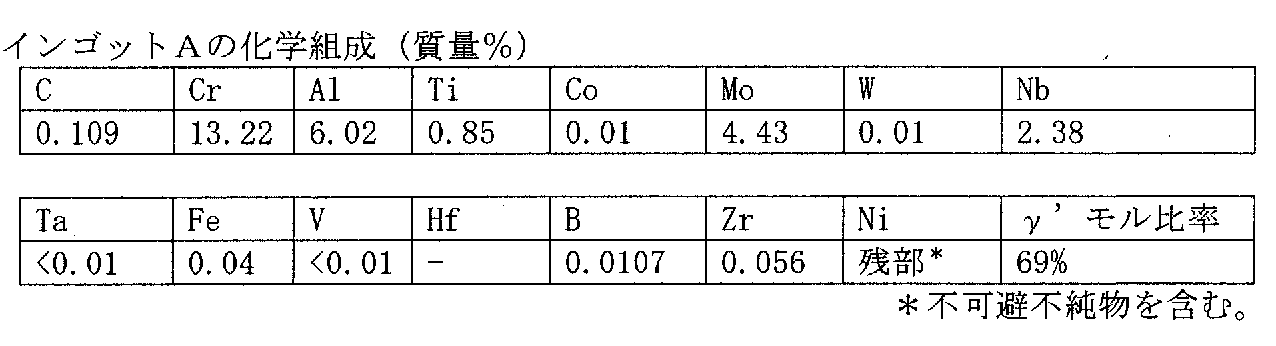
この成分組成のインゴットAに保持温度1200℃、保持時間8時間の熱処理を施し、炉冷してから、インゴットAの長さ方向に平行方向に長さ150mm、直径60mmの円柱形状の材料を採取した。この円柱形状の材料をSUS304製カプセルに封止して、熱間押出に供した。熱間押出の条件は、押出温度1100℃、押出比10(カプセルを含む)、押出ステム速度15mm/sであった。熱間押出を行って、これを室温まで冷却後、上記のカプセル素材を除去することにより、直径27mmの押出材(第1の加工材)を得た。
(b)第1の熱処理材(素材)を作製する工程
上記の押出材を、大気中で、1000℃、1050℃、1100℃、1150℃、1200℃のそれぞれの熱処理温度に加熱して、熱処理を施し(保持時間1時間)、炉冷して第1の熱処理材を得た(以下、「素材」と言う)。また、熱処理温度が1200℃のものについては、空冷もした。そして、これら6条件の熱処理を施して得た6種の素材に、熱処理自体を行わなかった(熱間押出のままの)素材も加えて、計7種の素材1~7[素材1(熱処理なし)、素材2(熱処理温度1000℃)、素材3(同1050℃)、素材4(同1100℃)、素材5(同1150℃)、素材6(同1200℃)、素材7(同1200℃。但し、熱処理後、空冷)]を作製した。
上記の押出材を、大気中で、1000℃、1050℃、1100℃、1150℃、1200℃のそれぞれの熱処理温度に加熱して、熱処理を施し(保持時間1時間)、炉冷して第1の熱処理材を得た(以下、「素材」と言う)。また、熱処理温度が1200℃のものについては、空冷もした。そして、これら6条件の熱処理を施して得た6種の素材に、熱処理自体を行わなかった(熱間押出のままの)素材も加えて、計7種の素材1~7[素材1(熱処理なし)、素材2(熱処理温度1000℃)、素材3(同1050℃)、素材4(同1100℃)、素材5(同1150℃)、素材6(同1200℃)、素材7(同1200℃。但し、熱処理後、空冷)]を作製した。
素材1~7を、軸線方向に平行に半割切断して、その切断面のミクロ組織(結晶粒径、炭化物形態)および硬さを評価した。
素材1~7の走査型電子顕微鏡(SEM像)観察による上記切断面の断面ミクロ組織を、図4~10の順で示す。このとき、断面ミクロ組織の倍率は2000倍を基本とすることができる。但し、結晶粒径が大きい場合、より多くの結晶粒数を確認するために、倍率を小さくすることができ、例えば、後述のEBSDによる結晶粒径が8μmを超えるような場合、倍率を1000倍にすることができる(素材6、7)。観察場所は、上記の切断面において、素材の表面から軸心に向かってD/4(Dは押出材直径)の距離入った位置とした。それぞれのミクロ組織には各種の炭化物(MC、M23C6等)が観察されたところ(図中の分散物)、熱処理温度が1200℃の素材6、7のミクロ組織には、M23C6が実質的に確認されなかった(0.1×10-2個/μm2以下であった)。硬さの評価は、上記の切断面において、素材の表面から軸心に向かってD/2の距離入った位置(つまり、軸心の位置)とした。
素材1~7の走査型電子顕微鏡(SEM像)観察による上記切断面の断面ミクロ組織を、図4~10の順で示す。このとき、断面ミクロ組織の倍率は2000倍を基本とすることができる。但し、結晶粒径が大きい場合、より多くの結晶粒数を確認するために、倍率を小さくすることができ、例えば、後述のEBSDによる結晶粒径が8μmを超えるような場合、倍率を1000倍にすることができる(素材6、7)。観察場所は、上記の切断面において、素材の表面から軸心に向かってD/4(Dは押出材直径)の距離入った位置とした。それぞれのミクロ組織には各種の炭化物(MC、M23C6等)が観察されたところ(図中の分散物)、熱処理温度が1200℃の素材6、7のミクロ組織には、M23C6が実質的に確認されなかった(0.1×10-2個/μm2以下であった)。硬さの評価は、上記の切断面において、素材の表面から軸心に向かってD/2の距離入った位置(つまり、軸心の位置)とした。
炭化物の分布形態については、上記の観察場所をEPMA(電子線マイクロアナライザー)で分析することで、MCの分布形態はそれを構成する金属元素であるNbのマッピング図で、M23C6のそれは同じくCrのマッピング図で、確認することができる。これらNbのマッピング図およびCrのマッピング図を、図4~10に併載しておく。図9(素材6)、図10(素材7)のCrのマッピング図では、Crが全面に亘って均等に分布しており(つまり、Crが基地中に固溶しており)、Crの偏在が(つまり、Crの炭化物が)実質的に認められなかった。そして、この図4~10のマッピング図を1視野(倍率2000倍なら50μm×65μm、倍率1000倍なら100μm×130μm)として、この1視野で確認した炭化物の面積率および個数密度を、この1視野と縦横で隣り合う別の3視野でも確認して(つまり、倍率2000倍なら100μm×130μm、倍率1000倍なら200μm×260μm)、これら4視野分の値を平均した値を、本発明に係る第1の熱処理材の炭化物形態として求めた。
そして、上記の観察場所において、素材1~7の結晶粒径をEBSD像で評価した。EBSDの測定条件は、上記の走査型電子顕微鏡(JIB-4700F(日本電子社製))に付属したEBSD測定システム「Aztec Version 3.2(Oxford Instruments社製)」を使用して、倍率:2000倍(素材6、7は1000倍)、スキャンステップ:0.1μmとし、結晶粒の定義は方位差15°以上を粒界とした。このときのEBSD像を、図4~10に併載しておく。そして、この測定条件および定義によって認識された粒のうちから上記のEPMAで確認したMC炭化物のものを除いた粒を結晶粒とし、この結晶粒について、個々の結晶粒の最大径(最大長さ)と個数との関係による結晶粒径分布を確認し、結晶粒の最大径の平均直径を求めた。そして、この1視野のEBSD像で求めた結晶粒の最大径の平均直径を、上記の炭化物形態のときと同様の要領で、この1視野と縦横で隣り合う別の3視野でも求めて、これら4視野分の値を平均した値を、本発明に係る第1の熱処理材の結晶粒径として求めた。
以上の結果を表2に示す。また、この結果について、熱処理温度と炭化物形態(面積率、個数密度)、結晶粒径および硬さそれぞれとの関係を図示したものを、素材7(空冷)のものを除いて、図11、図12、図13および図14の順に示す。図11および図12において、熱処理温度が上がると、1100℃と1150℃との間で、MCの面積率および個数密度と、M23C6の面積率および個数密度とが逆転し、MCの方が面積率、個数密度が多くなっている。
以上の結果を表2に示す。また、この結果について、熱処理温度と炭化物形態(面積率、個数密度)、結晶粒径および硬さそれぞれとの関係を図示したものを、素材7(空冷)のものを除いて、図11、図12、図13および図14の順に示す。図11および図12において、熱処理温度が上がると、1100℃と1150℃との間で、MCの面積率および個数密度と、M23C6の面積率および個数密度とが逆転し、MCの方が面積率、個数密度が多くなっている。
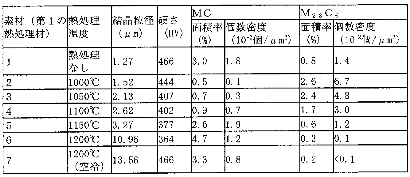
(c)第2の加工材を作製する工程
次に、素材1~7から直径6mm、長さ60mmの棒材を切り出した。棒材の長手方向は押出材の軸線方向に平行に取った。
この棒材に、回転式スエジング装置を用いて、室温(約25℃)で12パスまでの複数パスの冷間塑性加工を施して、それぞれの記号に対応する第2の加工材1~7を作製した。各パスの加工率(減面率)は30%以下とした。また、各パス間には熱処理を行わなかった。パススケジュールを表3に示す。そして、このパススケジュールで、最初の6.0mmの直径から加工可能であった直径および減面率(つまり、加工材が破断したパス前の直径および減面率)を評価した。また、そのときの硬さ(軸線方向に平行に半割切断したときの、軸心の位置での断面硬さ)も測定した。結果を表4に示す。

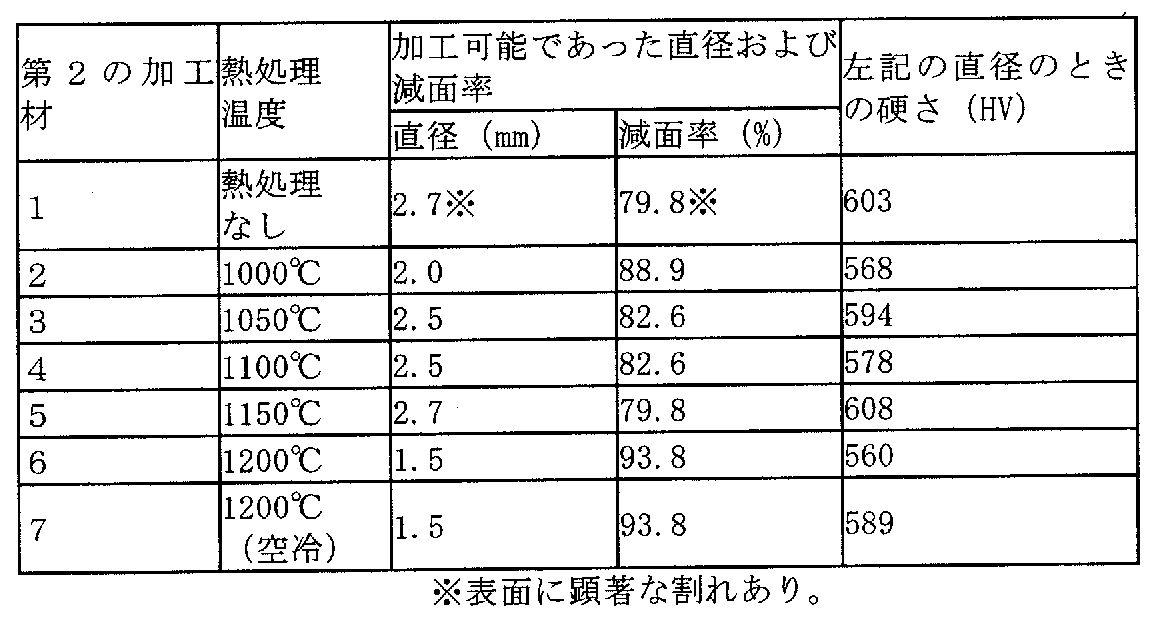
表4の結果について、その冷間塑性加工前の押出材に施した熱処理の温度と、冷間塑性加工性(減面率)との関係を図3に示す。図3より、押出材に熱処理を施したことで、素材の加工性が飛躍的に向上した(ステージ1)。そして、熱処理温度が1000℃を超えた辺りから、一旦、加工性が低下する傾向となるものの(ステージ2)、当初の加工性は維持して、熱処理温度が1150℃を超えた辺りから再び上昇に転じて、加工性がさらに向上した(ステージ3)。
以上、実施例によりNi基超耐熱合金の細線を、冷間塑性加工により製造できることを示した。本発明の製造方法により製造したNi基超耐熱合金は冷間で塑性加工することで、任意の線径の線材等に加工できる。本実施例は、線材の製造について行なったが、板材など他の形状の製造への適用も可能である。
Claims (7)
- Ni基超耐熱合金の製造方法であって、
(a)炭素含有量が0.05~0.25質量%であり、かつ700℃におけるガンマプライム相の平衡析出量が35モル%以上の成分組成を有する材料に、900℃以上の温度で塑性加工を行なった後に冷却して、第1の加工材を作製する工程と、
(b)前記第1の加工材を900℃以上の温度に加熱して熱処理を行い、第1の熱処理材を作製する工程と
を含む、Ni基超耐熱合金の製造方法。 - (c)前記第1の熱処理材に、500℃以下の温度で塑性加工を行ない、第2の加工材を作製する工程と
をさらに含む、請求項1に記載されたNi基超耐熱合金の製造方法。 - (d)前記第2の加工材に、900℃以上の温度で熱処理を行う工程と
をさらに含む、請求項2に記載されたNi基超耐熱合金の製造方法。 - 前記Ni基超耐熱合金が、質量%で、
C:0.05~0.25%、
Cr:8.0~25.0%、
Al:0.5~8.0%、
Ti:0.4~7.0%、
Co:0~28.0%、
Mo:0~8.0%、
W:0~15.0%、
Nb:0~4.0%、
Ta:0~5.0%、
Fe:0~10.0%、
V:0~1.2%、
Hf:0~3.0%、
B:0~0.300%、
Zr:0~0.300%
を含み、残部がNiおよび不純物からなる、請求項1から請求項3までのいずれか1項に記載されたNi基超耐熱合金の製造方法。 - 冷間塑性加工用のNi基超耐熱合金であって、
炭素含有量が0.05~0.25質量%であり、かつ700℃におけるガンマプライム相の平衡析出量が35モル%以上の成分組成を有し、
断面組織において、M23C6の面積率が4.0面積%以下であり、結晶粒の最大径の平均粒径が1.4~100μmである、Ni基超耐熱合金。 - 硬さが460HV以下である、請求項5に記載されたNi基超耐熱合金。
- 前記Ni基超耐熱合金が、質量%で、
C:0.05~0.25%、
Cr:8.0~25.0%、
Al:0.5~8.0%、
Ti:0.4~7.0%、
Co:0~28.0%、
Mo:0~8.0%、
W:0~15.0%、
Nb:0~4.0%、
Ta:0~5.0%、
Fe:0~10.0%、
V:0~1.2%、
Hf:0~3.0%、
B:0~0.300%、
Zr:0~0.300%
を含み、残部がNiおよび不純物からなる、請求項5または請求項6に記載されたNi基超耐熱合金。
Priority Applications (1)
| Application Number | Priority Date | Filing Date | Title |
|---|---|---|---|
| JP2020520084A JP6826766B1 (ja) | 2019-03-26 | 2020-01-20 | Ni基超耐熱合金の製造方法およびNi基超耐熱合金 |
Applications Claiming Priority (4)
| Application Number | Priority Date | Filing Date | Title |
|---|---|---|---|
| JP2019-059122 | 2019-03-26 | ||
| JP2019059122 | 2019-03-26 | ||
| JP2019144497 | 2019-08-06 | ||
| JP2019-144497 | 2019-08-06 |
Publications (1)
| Publication Number | Publication Date |
|---|---|
| WO2020195049A1 true WO2020195049A1 (ja) | 2020-10-01 |
Family
ID=72609738
Family Applications (1)
| Application Number | Title | Priority Date | Filing Date |
|---|---|---|---|
| PCT/JP2020/001725 Ceased WO2020195049A1 (ja) | 2019-03-26 | 2020-01-20 | Ni基超耐熱合金の製造方法およびNi基超耐熱合金 |
Country Status (2)
| Country | Link |
|---|---|
| JP (1) | JP6826766B1 (ja) |
| WO (1) | WO2020195049A1 (ja) |
Cited By (8)
| Publication number | Priority date | Publication date | Assignee | Title |
|---|---|---|---|---|
| CN112281099A (zh) * | 2020-10-13 | 2021-01-29 | 江苏联捷冶金设备有限公司 | 钨钴合金沉没辊及其制备方法 |
| CN113584370A (zh) * | 2021-07-30 | 2021-11-02 | 北京北冶功能材料有限公司 | 一种低密度高强度高熵高温合金及其制备方法 |
| CN113604706A (zh) * | 2021-07-30 | 2021-11-05 | 北京北冶功能材料有限公司 | 一种低密度低膨胀高熵高温合金及其制备方法 |
| CN114752817A (zh) * | 2022-04-08 | 2022-07-15 | 南京工程学院 | 一种高温合金模具材料及其制备方法和应用 |
| KR20220138825A (ko) * | 2021-04-06 | 2022-10-13 | 다이도 토쿠슈코 카부시키가이샤 | 내열 합금 부재, 이것에 이용하는 소재 및 이들의 제조 방법 |
| CN117286371A (zh) * | 2023-09-05 | 2023-12-26 | 钢铁研究总院有限公司 | 一种镍基耐热合金及其制备方法和应用 |
| WO2024139240A1 (zh) * | 2022-12-29 | 2024-07-04 | 北京钢研高纳科技股份有限公司 | 镍基高温合金及其制备方法和结构件 |
| CN119433395A (zh) * | 2024-11-14 | 2025-02-14 | 重庆材料研究院有限公司 | 一种68NiCrWCoTiAl合金的双联固溶处理工艺 |
Citations (4)
| Publication number | Priority date | Publication date | Assignee | Title |
|---|---|---|---|---|
| JP2014070230A (ja) * | 2012-09-27 | 2014-04-21 | Hitachi Metals Ltd | Ni基超耐熱合金の製造方法 |
| JP2017514998A (ja) * | 2014-03-14 | 2017-06-08 | オウベル・アンド・デュヴァル | 析出硬化ニッケル合金、前記合金でできた部品、及びその製造方法 |
| WO2018155446A1 (ja) * | 2017-02-21 | 2018-08-30 | 日立金属株式会社 | Ni基超耐熱合金およびその製造方法 |
| WO2019004176A1 (ja) * | 2017-06-30 | 2019-01-03 | 日立金属株式会社 | Ni基超耐熱合金ワイヤの製造方法およびNi基超耐熱合金ワイヤ |
-
2020
- 2020-01-20 WO PCT/JP2020/001725 patent/WO2020195049A1/ja not_active Ceased
- 2020-01-20 JP JP2020520084A patent/JP6826766B1/ja active Active
Patent Citations (4)
| Publication number | Priority date | Publication date | Assignee | Title |
|---|---|---|---|---|
| JP2014070230A (ja) * | 2012-09-27 | 2014-04-21 | Hitachi Metals Ltd | Ni基超耐熱合金の製造方法 |
| JP2017514998A (ja) * | 2014-03-14 | 2017-06-08 | オウベル・アンド・デュヴァル | 析出硬化ニッケル合金、前記合金でできた部品、及びその製造方法 |
| WO2018155446A1 (ja) * | 2017-02-21 | 2018-08-30 | 日立金属株式会社 | Ni基超耐熱合金およびその製造方法 |
| WO2019004176A1 (ja) * | 2017-06-30 | 2019-01-03 | 日立金属株式会社 | Ni基超耐熱合金ワイヤの製造方法およびNi基超耐熱合金ワイヤ |
Cited By (15)
| Publication number | Priority date | Publication date | Assignee | Title |
|---|---|---|---|---|
| CN112281099A (zh) * | 2020-10-13 | 2021-01-29 | 江苏联捷冶金设备有限公司 | 钨钴合金沉没辊及其制备方法 |
| KR20220138825A (ko) * | 2021-04-06 | 2022-10-13 | 다이도 토쿠슈코 카부시키가이샤 | 내열 합금 부재, 이것에 이용하는 소재 및 이들의 제조 방법 |
| KR102684607B1 (ko) * | 2021-04-06 | 2024-07-11 | 다이도 토쿠슈코 카부시키가이샤 | 내열 합금 부재, 이것에 이용하는 소재 및 이들의 제조 방법 |
| CN113584370A (zh) * | 2021-07-30 | 2021-11-02 | 北京北冶功能材料有限公司 | 一种低密度高强度高熵高温合金及其制备方法 |
| CN113604706A (zh) * | 2021-07-30 | 2021-11-05 | 北京北冶功能材料有限公司 | 一种低密度低膨胀高熵高温合金及其制备方法 |
| CN114752817A (zh) * | 2022-04-08 | 2022-07-15 | 南京工程学院 | 一种高温合金模具材料及其制备方法和应用 |
| CN114752817B (zh) * | 2022-04-08 | 2022-09-23 | 南京工程学院 | 一种高温合金模具材料及其制备方法和应用 |
| JP7693845B2 (ja) | 2022-12-29 | 2025-06-17 | 北京鋼研高納科技股▲フン▼有限公司 | ニッケル基高温合金、その調製方法および構造部材 |
| WO2024139240A1 (zh) * | 2022-12-29 | 2024-07-04 | 北京钢研高纳科技股份有限公司 | 镍基高温合金及其制备方法和结构件 |
| US12421575B2 (en) | 2022-12-29 | 2025-09-23 | Gaona Aero Material Co., Ltd. | Nickel-based superalloy and preparation method therefor, and structural component |
| JP2025504728A (ja) * | 2022-12-29 | 2025-02-19 | 北京鋼研高納科技股▲フン▼有限公司 | ニッケル基高温合金、その調製方法および構造部材 |
| CN117286371A (zh) * | 2023-09-05 | 2023-12-26 | 钢铁研究总院有限公司 | 一种镍基耐热合金及其制备方法和应用 |
| CN117286371B (zh) * | 2023-09-05 | 2025-10-31 | 钢铁研究总院有限公司 | 一种镍基耐热合金及其制备方法和应用 |
| CN119433395A (zh) * | 2024-11-14 | 2025-02-14 | 重庆材料研究院有限公司 | 一种68NiCrWCoTiAl合金的双联固溶处理工艺 |
| CN119433395B (zh) * | 2024-11-14 | 2026-01-16 | 重庆材料研究院有限公司 | 一种68NiCrWCoTiAl合金的双联固溶处理工艺 |
Also Published As
| Publication number | Publication date |
|---|---|
| JPWO2020195049A1 (ja) | 2021-04-08 |
| JP6826766B1 (ja) | 2021-02-10 |
Similar Documents
| Publication | Publication Date | Title |
|---|---|---|
| JP6826766B1 (ja) | Ni基超耐熱合金の製造方法およびNi基超耐熱合金 | |
| JP6889418B2 (ja) | Ni基超耐熱合金の製造方法およびNi基超耐熱合金 | |
| JP6422045B1 (ja) | Ni基超耐熱合金およびその製造方法 | |
| US11085104B2 (en) | Method for manufacturing Ni-based heat-resistant superalloy wire, and Ni-based heat-resistant super alloy wire | |
| EP3441489B1 (en) | Method for manufacturing ni-based alloy member | |
| JP5652730B1 (ja) | Ni基超耐熱合金及びその製造方法 | |
| JP6826879B2 (ja) | Ni基超耐熱合金の製造方法 | |
| JP6719216B2 (ja) | α−β型チタン合金 | |
| JP2018095941A (ja) | 耐熱Ti合金及びその製造方法 | |
| JP6748951B2 (ja) | Ni基超耐熱合金の製造方法およびNi基超耐熱合金 | |
| JP2021130861A (ja) | α+β型チタン合金棒材の製造方法 | |
| JP4493029B2 (ja) | 被削性及び熱間加工性に優れたα−β型チタン合金 | |
| JP2018154922A (ja) | α+β型チタン合金押出形材 | |
| EP3520915A1 (en) | Method of manufacturing ni-based super heat resistant alloy extruded material, and ni-based super heat resistant alloy extruded material | |
| JP2019183263A (ja) | 冷間加工用Ni基超耐熱合金素材 | |
| WO2017170433A1 (ja) | Ni基超耐熱合金の製造方法 | |
| WO2016152663A1 (ja) | α-β型チタン合金 | |
| TWI564398B (zh) | 鎳基合金及其製造方法 | |
| JP2021011601A (ja) | Ni基超耐熱合金の製造方法 | |
| JP2024066436A (ja) | Ni基合金及びその製造方法、並びに、Ni基合金部材 | |
| JPH06240391A (ja) | 高温強度に優れたニッケル−タングステン合金、その製造方法およびそれを用いた熱間加工用治具 | |
| JP2020001047A (ja) | Ni基超耐熱合金溶接材 |
Legal Events
| Date | Code | Title | Description |
|---|---|---|---|
| ENP | Entry into the national phase |
Ref document number: 2020520084 Country of ref document: JP Kind code of ref document: A |
|
| 121 | Ep: the epo has been informed by wipo that ep was designated in this application |
Ref document number: 20776711 Country of ref document: EP Kind code of ref document: A1 |
|
| NENP | Non-entry into the national phase |
Ref country code: DE |
|
| 122 | Ep: pct application non-entry in european phase |
Ref document number: 20776711 Country of ref document: EP Kind code of ref document: A1 |