WO2020194972A1 - 絶縁シート - Google Patents
絶縁シート Download PDFInfo
- Publication number
- WO2020194972A1 WO2020194972A1 PCT/JP2019/051286 JP2019051286W WO2020194972A1 WO 2020194972 A1 WO2020194972 A1 WO 2020194972A1 JP 2019051286 W JP2019051286 W JP 2019051286W WO 2020194972 A1 WO2020194972 A1 WO 2020194972A1
- Authority
- WO
- WIPO (PCT)
- Prior art keywords
- insulating sheet
- insulating
- particles
- binder resin
- volume
- Prior art date
Links
- 239000002245 particle Substances 0.000 claims abstract description 213
- 229920005989 resin Polymers 0.000 claims abstract description 168
- 239000011347 resin Substances 0.000 claims abstract description 168
- 239000011230 binding agent Substances 0.000 claims abstract description 113
- 229910052582 BN Inorganic materials 0.000 claims description 45
- PZNSFCLAULLKQX-UHFFFAOYSA-N Boron nitride Chemical compound N#B PZNSFCLAULLKQX-UHFFFAOYSA-N 0.000 claims description 45
- 239000004760 aramid Substances 0.000 claims description 36
- 229920003235 aromatic polyamide Polymers 0.000 claims description 36
- 239000002243 precursor Substances 0.000 claims description 36
- 238000000034 method Methods 0.000 claims description 35
- 239000002002 slurry Substances 0.000 claims description 24
- 238000002156 mixing Methods 0.000 claims description 20
- 238000009413 insulation Methods 0.000 claims description 19
- 238000003825 pressing Methods 0.000 claims description 15
- 239000013557 residual solvent Substances 0.000 claims description 15
- 238000004519 manufacturing process Methods 0.000 claims description 12
- 150000003839 salts Chemical class 0.000 claims description 12
- 230000003746 surface roughness Effects 0.000 claims description 12
- 230000015556 catabolic process Effects 0.000 claims description 11
- 239000002904 solvent Substances 0.000 claims description 11
- 238000000465 moulding Methods 0.000 claims description 9
- 238000001035 drying Methods 0.000 claims description 8
- 238000005979 thermal decomposition reaction Methods 0.000 claims description 7
- 238000002844 melting Methods 0.000 claims description 6
- 230000008018 melting Effects 0.000 claims description 6
- 238000007493 shaping process Methods 0.000 claims description 4
- 230000000052 comparative effect Effects 0.000 description 23
- XLYOFNOQVPJJNP-UHFFFAOYSA-N water Substances O XLYOFNOQVPJJNP-UHFFFAOYSA-N 0.000 description 21
- 239000010410 layer Substances 0.000 description 18
- 239000012779 reinforcing material Substances 0.000 description 10
- 238000011049 filling Methods 0.000 description 9
- 230000005484 gravity Effects 0.000 description 9
- 238000010438 heat treatment Methods 0.000 description 9
- 238000005259 measurement Methods 0.000 description 9
- 239000000654 additive Substances 0.000 description 8
- KWGKDLIKAYFUFQ-UHFFFAOYSA-M lithium chloride Chemical compound [Li+].[Cl-] KWGKDLIKAYFUFQ-UHFFFAOYSA-M 0.000 description 8
- UXVMQQNJUSDDNG-UHFFFAOYSA-L Calcium chloride Chemical compound [Cl-].[Cl-].[Ca+2] UXVMQQNJUSDDNG-UHFFFAOYSA-L 0.000 description 7
- SECXISVLQFMRJM-UHFFFAOYSA-N N-Methylpyrrolidone Chemical compound CN1CCCC1=O SECXISVLQFMRJM-UHFFFAOYSA-N 0.000 description 7
- 239000012790 adhesive layer Substances 0.000 description 7
- 239000011800 void material Substances 0.000 description 7
- 238000005406 washing Methods 0.000 description 7
- ZAMOUSCENKQFHK-UHFFFAOYSA-N Chlorine atom Chemical compound [Cl] ZAMOUSCENKQFHK-UHFFFAOYSA-N 0.000 description 6
- 239000000460 chlorine Substances 0.000 description 6
- 229910052801 chlorine Inorganic materials 0.000 description 6
- 239000000463 material Substances 0.000 description 6
- -1 polytetrafluoroethylene Polymers 0.000 description 6
- 238000001878 scanning electron micrograph Methods 0.000 description 6
- 239000004065 semiconductor Substances 0.000 description 6
- 238000012360 testing method Methods 0.000 description 6
- 230000000694 effects Effects 0.000 description 5
- 230000001965 increasing effect Effects 0.000 description 5
- 239000000203 mixture Substances 0.000 description 5
- 239000011856 silicon-based particle Substances 0.000 description 5
- 229920005992 thermoplastic resin Polymers 0.000 description 5
- 229920000106 Liquid crystal polymer Polymers 0.000 description 4
- 239000004977 Liquid-crystal polymers (LCPs) Substances 0.000 description 4
- 239000002033 PVDF binder Substances 0.000 description 4
- 239000004696 Poly ether ether ketone Substances 0.000 description 4
- 239000004697 Polyetherimide Substances 0.000 description 4
- 239000004734 Polyphenylene sulfide Substances 0.000 description 4
- 230000000996 additive effect Effects 0.000 description 4
- 239000000835 fiber Substances 0.000 description 4
- 239000011521 glass Substances 0.000 description 4
- 230000017525 heat dissipation Effects 0.000 description 4
- 229920002530 polyetherether ketone Polymers 0.000 description 4
- 229920001601 polyetherimide Polymers 0.000 description 4
- 229920000069 polyphenylene sulfide Polymers 0.000 description 4
- 239000004810 polytetrafluoroethylene Substances 0.000 description 4
- 229920001343 polytetrafluoroethylene Polymers 0.000 description 4
- 229920002981 polyvinylidene fluoride Polymers 0.000 description 4
- 230000008569 process Effects 0.000 description 4
- 238000003756 stirring Methods 0.000 description 4
- 239000000126 substance Substances 0.000 description 4
- 239000002344 surface layer Substances 0.000 description 4
- 229920001494 Technora Polymers 0.000 description 3
- 239000002826 coolant Substances 0.000 description 3
- 238000009826 distribution Methods 0.000 description 3
- 239000010954 inorganic particle Substances 0.000 description 3
- 230000003287 optical effect Effects 0.000 description 3
- 229920001230 polyarylate Polymers 0.000 description 3
- 239000000758 substrate Substances 0.000 description 3
- 239000004950 technora Substances 0.000 description 3
- 238000012935 Averaging Methods 0.000 description 2
- WKBOTKDWSSQWDR-UHFFFAOYSA-N Bromine atom Chemical compound [Br] WKBOTKDWSSQWDR-UHFFFAOYSA-N 0.000 description 2
- OKTJSMMVPCPJKN-UHFFFAOYSA-N Carbon Chemical compound [C] OKTJSMMVPCPJKN-UHFFFAOYSA-N 0.000 description 2
- VEXZGXHMUGYJMC-UHFFFAOYSA-M Chloride anion Chemical compound [Cl-] VEXZGXHMUGYJMC-UHFFFAOYSA-M 0.000 description 2
- IAZDPXIOMUYVGZ-UHFFFAOYSA-N Dimethylsulphoxide Chemical compound CS(C)=O IAZDPXIOMUYVGZ-UHFFFAOYSA-N 0.000 description 2
- 229920012266 Poly(ether sulfone) PES Polymers 0.000 description 2
- 238000004458 analytical method Methods 0.000 description 2
- 239000012298 atmosphere Substances 0.000 description 2
- GDTBXPJZTBHREO-UHFFFAOYSA-N bromine Substances BrBr GDTBXPJZTBHREO-UHFFFAOYSA-N 0.000 description 2
- 229910052794 bromium Inorganic materials 0.000 description 2
- 239000003086 colorant Substances 0.000 description 2
- 229920001577 copolymer Polymers 0.000 description 2
- 239000007822 coupling agent Substances 0.000 description 2
- 238000005520 cutting process Methods 0.000 description 2
- 230000007547 defect Effects 0.000 description 2
- 238000002845 discoloration Methods 0.000 description 2
- 239000003822 epoxy resin Substances 0.000 description 2
- 239000000945 filler Substances 0.000 description 2
- 239000003063 flame retardant Substances 0.000 description 2
- 239000007789 gas Substances 0.000 description 2
- 239000003112 inhibitor Substances 0.000 description 2
- 150000002500 ions Chemical class 0.000 description 2
- 239000004973 liquid crystal related substance Substances 0.000 description 2
- 229910052751 metal Inorganic materials 0.000 description 2
- 239000002184 metal Substances 0.000 description 2
- 229920002312 polyamide-imide Polymers 0.000 description 2
- 229920002577 polybenzoxazole Polymers 0.000 description 2
- 229920000647 polyepoxide Polymers 0.000 description 2
- 239000009719 polyimide resin Substances 0.000 description 2
- 229920000642 polymer Polymers 0.000 description 2
- 239000011342 resin composition Substances 0.000 description 2
- HBMJWWWQQXIZIP-UHFFFAOYSA-N silicon carbide Chemical compound [Si+]#[C-] HBMJWWWQQXIZIP-UHFFFAOYSA-N 0.000 description 2
- 229910010271 silicon carbide Inorganic materials 0.000 description 2
- 239000004094 surface-active agent Substances 0.000 description 2
- MHSKRLJMQQNJNC-UHFFFAOYSA-N terephthalamide Chemical compound NC(=O)C1=CC=C(C(N)=O)C=C1 MHSKRLJMQQNJNC-UHFFFAOYSA-N 0.000 description 2
- 229920001169 thermoplastic Polymers 0.000 description 2
- 239000004416 thermosoftening plastic Substances 0.000 description 2
- 230000004580 weight loss Effects 0.000 description 2
- RNFJDJUURJAICM-UHFFFAOYSA-N 2,2,4,4,6,6-hexaphenoxy-1,3,5-triaza-2$l^{5},4$l^{5},6$l^{5}-triphosphacyclohexa-1,3,5-triene Chemical compound N=1P(OC=2C=CC=CC=2)(OC=2C=CC=CC=2)=NP(OC=2C=CC=CC=2)(OC=2C=CC=CC=2)=NP=1(OC=1C=CC=CC=1)OC1=CC=CC=C1 RNFJDJUURJAICM-UHFFFAOYSA-N 0.000 description 1
- 239000004953 Aliphatic polyamide Substances 0.000 description 1
- FXHOOIRPVKKKFG-UHFFFAOYSA-N N,N-Dimethylacetamide Chemical compound CN(C)C(C)=O FXHOOIRPVKKKFG-UHFFFAOYSA-N 0.000 description 1
- 229910052581 Si3N4 Inorganic materials 0.000 description 1
- 229920000561 Twaron Polymers 0.000 description 1
- 238000002441 X-ray diffraction Methods 0.000 description 1
- 230000002411 adverse Effects 0.000 description 1
- 229920003231 aliphatic polyamide Polymers 0.000 description 1
- 125000003118 aryl group Chemical group 0.000 description 1
- QVGXLLKOCUKJST-UHFFFAOYSA-N atomic oxygen Chemical compound [O] QVGXLLKOCUKJST-UHFFFAOYSA-N 0.000 description 1
- 239000011324 bead Substances 0.000 description 1
- RIOXQFHNBCKOKP-UHFFFAOYSA-N benomyl Chemical compound C1=CC=C2N(C(=O)NCCCC)C(NC(=O)OC)=NC2=C1 RIOXQFHNBCKOKP-UHFFFAOYSA-N 0.000 description 1
- 230000015572 biosynthetic process Effects 0.000 description 1
- 239000001110 calcium chloride Substances 0.000 description 1
- 229910001628 calcium chloride Inorganic materials 0.000 description 1
- 229960005286 carbaryl Drugs 0.000 description 1
- 229910052799 carbon Inorganic materials 0.000 description 1
- 239000000919 ceramic Substances 0.000 description 1
- 238000003889 chemical engineering Methods 0.000 description 1
- 239000011248 coating agent Substances 0.000 description 1
- 238000000576 coating method Methods 0.000 description 1
- 239000002131 composite material Substances 0.000 description 1
- 150000001875 compounds Chemical class 0.000 description 1
- 238000009833 condensation Methods 0.000 description 1
- 230000005494 condensation Effects 0.000 description 1
- 239000004020 conductor Substances 0.000 description 1
- PMHQVHHXPFUNSP-UHFFFAOYSA-M copper(1+);methylsulfanylmethane;bromide Chemical compound Br[Cu].CSC PMHQVHHXPFUNSP-UHFFFAOYSA-M 0.000 description 1
- 239000013078 crystal Substances 0.000 description 1
- 238000011033 desalting Methods 0.000 description 1
- 238000004455 differential thermal analysis Methods 0.000 description 1
- 238000009792 diffusion process Methods 0.000 description 1
- BXKDSDJJOVIHMX-UHFFFAOYSA-N edrophonium chloride Chemical compound [Cl-].CC[N+](C)(C)C1=CC=CC(O)=C1 BXKDSDJJOVIHMX-UHFFFAOYSA-N 0.000 description 1
- 238000010292 electrical insulation Methods 0.000 description 1
- 238000005516 engineering process Methods 0.000 description 1
- 230000002708 enhancing effect Effects 0.000 description 1
- 238000011156 evaluation Methods 0.000 description 1
- 238000001125 extrusion Methods 0.000 description 1
- 239000010439 graphite Substances 0.000 description 1
- 229910002804 graphite Inorganic materials 0.000 description 1
- 238000013007 heat curing Methods 0.000 description 1
- 230000020169 heat generation Effects 0.000 description 1
- 239000001307 helium Substances 0.000 description 1
- 229910052734 helium Inorganic materials 0.000 description 1
- SWQJXJOGLNCZEY-UHFFFAOYSA-N helium atom Chemical compound [He] SWQJXJOGLNCZEY-UHFFFAOYSA-N 0.000 description 1
- 238000007731 hot pressing Methods 0.000 description 1
- 230000006872 improvement Effects 0.000 description 1
- 238000001746 injection moulding Methods 0.000 description 1
- 239000011256 inorganic filler Substances 0.000 description 1
- 229910003475 inorganic filler Inorganic materials 0.000 description 1
- 239000011810 insulating material Substances 0.000 description 1
- 230000010354 integration Effects 0.000 description 1
- 238000004898 kneading Methods 0.000 description 1
- 238000010030 laminating Methods 0.000 description 1
- 238000007561 laser diffraction method Methods 0.000 description 1
- 229940057995 liquid paraffin Drugs 0.000 description 1
- 239000000395 magnesium oxide Substances 0.000 description 1
- CPLXHLVBOLITMK-UHFFFAOYSA-N magnesium oxide Inorganic materials [Mg]=O CPLXHLVBOLITMK-UHFFFAOYSA-N 0.000 description 1
- AXZKOIWUVFPNLO-UHFFFAOYSA-N magnesium;oxygen(2-) Chemical compound [O-2].[Mg+2] AXZKOIWUVFPNLO-UHFFFAOYSA-N 0.000 description 1
- 230000014759 maintenance of location Effects 0.000 description 1
- 238000000691 measurement method Methods 0.000 description 1
- 125000001624 naphthyl group Chemical group 0.000 description 1
- JMANVNJQNLATNU-UHFFFAOYSA-N oxalonitrile Chemical compound N#CC#N JMANVNJQNLATNU-UHFFFAOYSA-N 0.000 description 1
- 230000003647 oxidation Effects 0.000 description 1
- 238000007254 oxidation reaction Methods 0.000 description 1
- TWNQGVIAIRXVLR-UHFFFAOYSA-N oxo(oxoalumanyloxy)alumane Chemical compound O=[Al]O[Al]=O TWNQGVIAIRXVLR-UHFFFAOYSA-N 0.000 description 1
- 239000001301 oxygen Substances 0.000 description 1
- 229910052760 oxygen Inorganic materials 0.000 description 1
- 239000003973 paint Substances 0.000 description 1
- 230000002093 peripheral effect Effects 0.000 description 1
- 230000035699 permeability Effects 0.000 description 1
- 239000005011 phenolic resin Substances 0.000 description 1
- 230000000704 physical effect Effects 0.000 description 1
- 229920001721 polyimide Polymers 0.000 description 1
- 239000000843 powder Substances 0.000 description 1
- 238000012545 processing Methods 0.000 description 1
- 230000001737 promoting effect Effects 0.000 description 1
- 239000002994 raw material Substances 0.000 description 1
- 230000009467 reduction Effects 0.000 description 1
- 238000011160 research Methods 0.000 description 1
- 238000004904 shortening Methods 0.000 description 1
- HQVNEWCFYHHQES-UHFFFAOYSA-N silicon nitride Chemical compound N12[Si]34N5[Si]62N3[Si]51N64 HQVNEWCFYHHQES-UHFFFAOYSA-N 0.000 description 1
- 229920002050 silicone resin Polymers 0.000 description 1
- 239000012798 spherical particle Substances 0.000 description 1
- 239000003381 stabilizer Substances 0.000 description 1
- 229920002725 thermoplastic elastomer Polymers 0.000 description 1
- 229920006259 thermoplastic polyimide Polymers 0.000 description 1
- 229920001187 thermosetting polymer Polymers 0.000 description 1
- 230000009466 transformation Effects 0.000 description 1
- 239000004762 twaron Substances 0.000 description 1
- 239000004034 viscosity adjusting agent Substances 0.000 description 1
Images


Classifications
-
- H—ELECTRICITY
- H01—ELECTRIC ELEMENTS
- H01L—SEMICONDUCTOR DEVICES NOT COVERED BY CLASS H10
- H01L23/00—Details of semiconductor or other solid state devices
- H01L23/34—Arrangements for cooling, heating, ventilating or temperature compensation ; Temperature sensing arrangements
- H01L23/36—Selection of materials, or shaping, to facilitate cooling or heating, e.g. heatsinks
- H01L23/373—Cooling facilitated by selection of materials for the device or materials for thermal expansion adaptation, e.g. carbon
- H01L23/3737—Organic materials with or without a thermoconductive filler
-
- H—ELECTRICITY
- H01—ELECTRIC ELEMENTS
- H01B—CABLES; CONDUCTORS; INSULATORS; SELECTION OF MATERIALS FOR THEIR CONDUCTIVE, INSULATING OR DIELECTRIC PROPERTIES
- H01B17/00—Insulators or insulating bodies characterised by their form
- H01B17/56—Insulating bodies
- H01B17/60—Composite insulating bodies
-
- C—CHEMISTRY; METALLURGY
- C04—CEMENTS; CONCRETE; ARTIFICIAL STONE; CERAMICS; REFRACTORIES
- C04B—LIME, MAGNESIA; SLAG; CEMENTS; COMPOSITIONS THEREOF, e.g. MORTARS, CONCRETE OR LIKE BUILDING MATERIALS; ARTIFICIAL STONE; CERAMICS; REFRACTORIES; TREATMENT OF NATURAL STONE
- C04B35/00—Shaped ceramic products characterised by their composition; Ceramics compositions; Processing powders of inorganic compounds preparatory to the manufacturing of ceramic products
- C04B35/515—Shaped ceramic products characterised by their composition; Ceramics compositions; Processing powders of inorganic compounds preparatory to the manufacturing of ceramic products based on non-oxide ceramics
- C04B35/58—Shaped ceramic products characterised by their composition; Ceramics compositions; Processing powders of inorganic compounds preparatory to the manufacturing of ceramic products based on non-oxide ceramics based on borides, nitrides, i.e. nitrides, oxynitrides, carbonitrides or oxycarbonitrides or silicides
- C04B35/583—Shaped ceramic products characterised by their composition; Ceramics compositions; Processing powders of inorganic compounds preparatory to the manufacturing of ceramic products based on non-oxide ceramics based on borides, nitrides, i.e. nitrides, oxynitrides, carbonitrides or oxycarbonitrides or silicides based on boron nitride
-
- C—CHEMISTRY; METALLURGY
- C04—CEMENTS; CONCRETE; ARTIFICIAL STONE; CERAMICS; REFRACTORIES
- C04B—LIME, MAGNESIA; SLAG; CEMENTS; COMPOSITIONS THEREOF, e.g. MORTARS, CONCRETE OR LIKE BUILDING MATERIALS; ARTIFICIAL STONE; CERAMICS; REFRACTORIES; TREATMENT OF NATURAL STONE
- C04B35/00—Shaped ceramic products characterised by their composition; Ceramics compositions; Processing powders of inorganic compounds preparatory to the manufacturing of ceramic products
- C04B35/622—Forming processes; Processing powders of inorganic compounds preparatory to the manufacturing of ceramic products
- C04B35/626—Preparing or treating the powders individually or as batches ; preparing or treating macroscopic reinforcing agents for ceramic products, e.g. fibres; mechanical aspects section B
- C04B35/63—Preparing or treating the powders individually or as batches ; preparing or treating macroscopic reinforcing agents for ceramic products, e.g. fibres; mechanical aspects section B using additives specially adapted for forming the products, e.g.. binder binders
- C04B35/632—Organic additives
- C04B35/634—Polymers
- C04B35/63448—Polymers obtained otherwise than by reactions only involving carbon-to-carbon unsaturated bonds
- C04B35/63468—Polyamides
-
- H—ELECTRICITY
- H01—ELECTRIC ELEMENTS
- H01B—CABLES; CONDUCTORS; INSULATORS; SELECTION OF MATERIALS FOR THEIR CONDUCTIVE, INSULATING OR DIELECTRIC PROPERTIES
- H01B13/00—Apparatus or processes specially adapted for manufacturing conductors or cables
- H01B13/06—Insulating conductors or cables
-
- H—ELECTRICITY
- H01—ELECTRIC ELEMENTS
- H01B—CABLES; CONDUCTORS; INSULATORS; SELECTION OF MATERIALS FOR THEIR CONDUCTIVE, INSULATING OR DIELECTRIC PROPERTIES
- H01B17/00—Insulators or insulating bodies characterised by their form
- H01B17/56—Insulating bodies
-
- H—ELECTRICITY
- H01—ELECTRIC ELEMENTS
- H01B—CABLES; CONDUCTORS; INSULATORS; SELECTION OF MATERIALS FOR THEIR CONDUCTIVE, INSULATING OR DIELECTRIC PROPERTIES
- H01B19/00—Apparatus or processes specially adapted for manufacturing insulators or insulating bodies
-
- H—ELECTRICITY
- H01—ELECTRIC ELEMENTS
- H01B—CABLES; CONDUCTORS; INSULATORS; SELECTION OF MATERIALS FOR THEIR CONDUCTIVE, INSULATING OR DIELECTRIC PROPERTIES
- H01B3/00—Insulators or insulating bodies characterised by the insulating materials; Selection of materials for their insulating or dielectric properties
- H01B3/02—Insulators or insulating bodies characterised by the insulating materials; Selection of materials for their insulating or dielectric properties mainly consisting of inorganic substances
- H01B3/12—Insulators or insulating bodies characterised by the insulating materials; Selection of materials for their insulating or dielectric properties mainly consisting of inorganic substances ceramics
-
- H—ELECTRICITY
- H01—ELECTRIC ELEMENTS
- H01B—CABLES; CONDUCTORS; INSULATORS; SELECTION OF MATERIALS FOR THEIR CONDUCTIVE, INSULATING OR DIELECTRIC PROPERTIES
- H01B3/00—Insulators or insulating bodies characterised by the insulating materials; Selection of materials for their insulating or dielectric properties
- H01B3/18—Insulators or insulating bodies characterised by the insulating materials; Selection of materials for their insulating or dielectric properties mainly consisting of organic substances
- H01B3/30—Insulators or insulating bodies characterised by the insulating materials; Selection of materials for their insulating or dielectric properties mainly consisting of organic substances plastics; resins; waxes
- H01B3/303—Macromolecular compounds obtained by reactions forming a linkage containing nitrogen with or without oxygen or carbon in the main chain of the macromolecule, not provided for in groups H01B3/38 or H01B3/302
- H01B3/305—Polyamides or polyesteramides
-
- H—ELECTRICITY
- H01—ELECTRIC ELEMENTS
- H01L—SEMICONDUCTOR DEVICES NOT COVERED BY CLASS H10
- H01L23/00—Details of semiconductor or other solid state devices
- H01L23/34—Arrangements for cooling, heating, ventilating or temperature compensation ; Temperature sensing arrangements
- H01L23/36—Selection of materials, or shaping, to facilitate cooling or heating, e.g. heatsinks
- H01L23/373—Cooling facilitated by selection of materials for the device or materials for thermal expansion adaptation, e.g. carbon
-
- H—ELECTRICITY
- H05—ELECTRIC TECHNIQUES NOT OTHERWISE PROVIDED FOR
- H05K—PRINTED CIRCUITS; CASINGS OR CONSTRUCTIONAL DETAILS OF ELECTRIC APPARATUS; MANUFACTURE OF ASSEMBLAGES OF ELECTRICAL COMPONENTS
- H05K7/00—Constructional details common to different types of electric apparatus
- H05K7/20—Modifications to facilitate cooling, ventilating, or heating
- H05K7/2039—Modifications to facilitate cooling, ventilating, or heating characterised by the heat transfer by conduction from the heat generating element to a dissipating body
-
- C—CHEMISTRY; METALLURGY
- C04—CEMENTS; CONCRETE; ARTIFICIAL STONE; CERAMICS; REFRACTORIES
- C04B—LIME, MAGNESIA; SLAG; CEMENTS; COMPOSITIONS THEREOF, e.g. MORTARS, CONCRETE OR LIKE BUILDING MATERIALS; ARTIFICIAL STONE; CERAMICS; REFRACTORIES; TREATMENT OF NATURAL STONE
- C04B2235/00—Aspects relating to ceramic starting mixtures or sintered ceramic products
- C04B2235/60—Aspects relating to the preparation, properties or mechanical treatment of green bodies or pre-forms
-
- C—CHEMISTRY; METALLURGY
- C04—CEMENTS; CONCRETE; ARTIFICIAL STONE; CERAMICS; REFRACTORIES
- C04B—LIME, MAGNESIA; SLAG; CEMENTS; COMPOSITIONS THEREOF, e.g. MORTARS, CONCRETE OR LIKE BUILDING MATERIALS; ARTIFICIAL STONE; CERAMICS; REFRACTORIES; TREATMENT OF NATURAL STONE
- C04B2235/00—Aspects relating to ceramic starting mixtures or sintered ceramic products
- C04B2235/70—Aspects relating to sintered or melt-casted ceramic products
- C04B2235/96—Properties of ceramic products, e.g. mechanical properties such as strength, toughness, wear resistance
- C04B2235/9607—Thermal properties, e.g. thermal expansion coefficient
-
- C—CHEMISTRY; METALLURGY
- C08—ORGANIC MACROMOLECULAR COMPOUNDS; THEIR PREPARATION OR CHEMICAL WORKING-UP; COMPOSITIONS BASED THEREON
- C08K—Use of inorganic or non-macromolecular organic substances as compounding ingredients
- C08K3/00—Use of inorganic substances as compounding ingredients
- C08K3/38—Boron-containing compounds
- C08K2003/382—Boron-containing compounds and nitrogen
Definitions
- the present disclosure is to rapidly diffuse the heat generated in heat-generating components such as semiconductor elements, power supplies, and light sources inside electrical products to mitigate a local temperature rise, or to transport heat to a location away from the heat-generating source. It relates to an insulating sheet having excellent in-plane thermal conductivity and thermal transport characteristics.
- Patent Document 1 As a method for increasing the thermal conductivity of a resin material having insulating properties and flexibility, a composite of an inorganic filler, particularly boron nitride and a resin material, has been proposed.
- the in-plane thermal conductivity of 24 W / (m ⁇ K) is achieved by containing 85% by volume of boron nitride in the thermoplastic elastomer and liquid paraffin.
- Patent Document 2 80% by volume of boron nitride is mixed with the fluororesin to achieve an in-plane thermal conductivity of 35 W / (m ⁇ K).
- Patent Document 3 an in-plane thermal conductivity of 42 W / (m ⁇ K) is achieved by mixing 83% by volume of boron nitride with an epoxy resin having a naphthalene structure and heat-curing it.
- the present disclosure aims to provide an insulating sheet having high thermal conductivity in the in-plane direction.
- a method for producing an insulating sheet which comprises a molding step of shaping and drying the slurry after the mixing step into a sheet to form an insulating sheet precursor, and a roll pressing step of roll-pressing the insulating sheet precursor.
- the insulating particles include flat particles.
- the insulating particles contain 50% by volume or more of boron nitride.
- FIG. 1 shows a schematic cross-sectional view of an insulating sheet according to one embodiment of the present disclosure.
- FIG. 2 shows a schematic cross-sectional view of the insulating sheet according to another embodiment of the present disclosure.
- FIG. 3 shows a schematic view of a cross section of an insulating sheet according to the prior art.
- FIG. 4 shows an SEM photograph of a cross section perpendicular to the surface direction of the insulating sheet according to the first embodiment.
- FIG. 5 shows an SEM photograph of a cross section of the insulating sheet according to the second embodiment perpendicular to the plane direction.
- FIG. 6 shows an SEM photograph of a cross section of the insulating sheet according to the third embodiment perpendicular to the plane direction.
- FIG. 1 shows a schematic cross-sectional view of an insulating sheet according to one embodiment of the present disclosure.
- FIG. 2 shows a schematic cross-sectional view of the insulating sheet according to another embodiment of the present disclosure.
- FIG. 3 shows a
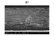
- FIG. 7 shows an SEM photograph of a cross section of the insulating sheet according to the fourth embodiment perpendicular to the plane direction.
- FIG. 8 shows an SEM photograph of a cross section of the insulating sheet according to the fifth embodiment perpendicular to the plane direction.
- FIG. 9 shows an SEM image of the insulating sheet precursor according to Reference Example 1 in a cross section perpendicular to the plane direction.
- FIG. 10 shows an SEM photograph of a cross section of the insulating sheet according to Comparative Example 1 perpendicular to the plane direction.
- FIG. 11 shows an SEM photograph of a cross section of the insulating sheet according to Comparative Example 2 perpendicular to the plane direction.
- the insulating sheet of the present disclosure is When the total of the insulating particles, the binder resin, and the voids is 100 area% for the entire cross section that contains the insulating particles and the binder resin and is perpendicular to the plane direction. 75-97 area% insulating particles, It contains 3 to 25 area% of binder resin and 10 area% or less of voids.
- the insulating sheet of the present disclosure has a relatively high filling rate of insulating particles and a relatively high thermal conductivity in the plane direction.
- FIG. 1 shows a schematic view of a cross section perpendicular to the plane direction of one embodiment of the insulating sheet according to the present disclosure.
- the filling rate of the insulating particles 11 is relatively high because the content of the binder resin 12 is reduced.
- the distance between the particles is relatively small due to the high filling rate of the insulating particles 11, resulting in high thermal conductivity in the in-plane direction. Be done.
- the thermal resistance caused by the resin is suppressed by reducing the content of the binder resin 12.
- the voids 13 in the sheet are also relatively reduced.
- the filling rate of the insulating particles 11 is further increased, and it is considered that the effect of increasing the thermal conductivity in the in-plane direction is further increased.
- the insulating sheet according to the present disclosure can be obtained, for example, by performing a roll press treatment on an insulating sheet precursor containing insulating particles and a binder resin.
- the sheet-shaped insulating sheet precursor contains a large amount of air bubbles.
- the insulating particles inside the sheet can be oriented in the in-plane direction of the sheet and the bubbles inside the insulating sheet precursor can be reduced, resulting in the result. It is considered that the thermal conductivity of the insulating sheet in the in-plane direction is enhanced.
- FIG. 3 shows a schematic view of a cross section of the insulating sheet 30 according to the prior art, which is perpendicular to the plane direction.
- the proportion of the binder resin 32 is relatively high, and the voids 33 between the particles are relatively large, so that the filling rate of the insulating particles 31 is relatively low.
- the distance between the insulating particles 31 is large, it is considered that high thermal conductivity in the plane direction cannot be obtained.
- the insulating sheet according to the present disclosure contains insulating particles.
- the insulating sheet according to the present disclosure contains 75 to 97 area% of the insulating particles in the entire cross section perpendicular to the plane direction, where the total of the insulating particles, the binder resin, and the voids is 100 area%. ..
- the content of the insulating particles is 75 area% or more, good thermal conductivity is obtained, and when it is 97 area% or less, an increase in the viscosity of the resin composition is suppressed, and molding is easy. To be secured.
- the insulating particles contained in the insulating sheet according to the present disclosure are 80 area% when the total of the insulating particles, the binder resin, and the voids is 100 area% with respect to the entire cross section perpendicular to the plane direction. 85 area% or more, 90 area% or more, and / or 96 area% or less, 95 area% or less, 94 area% or less, 93 area% or less, 92 area% or less, or 91 area% or less. It may be.
- the "area%" of the insulating particles is perpendicular to the surface direction of the insulating sheet, where the total of the insulating particles, the binder resin, and the voids is 100 area% for the entire cross section perpendicular to the surface direction. It can be calculated by taking a cross section with a scanning electron microscope (SEM) and measuring the total area of insulating particles present in a certain area in the acquired image.
- SEM scanning electron microscope
- the insulating particles are set by setting the fixed area so that the additive is not included in the fixed area.
- the binder resin, and the voids can be calculated as "area%" of the insulating particles with the total of 100 area%.
- the insulating particles are not particularly limited, and for example, carbon nitride, aluminum nitride, aluminum oxide, magnesium oxide, silicon nitride, silicon carbide, metallic silicon particles whose surface is insulated, and carbon whose surface is coated with an insulating material such as a resin.
- Examples include fibers and graphite, and polymer-based fillers. From the viewpoint of thermal conductivity and insulating properties in the plane direction, it is preferable that the insulating particles are boron nitride, particularly hexagonal boron nitride.
- the average particle size of the insulating particles is preferably 1 to 200 ⁇ m, more preferably 5 to 200 ⁇ m, still more preferably 5 to 100 ⁇ m, and particularly preferably 10 to 100 ⁇ m.
- the average particle size is the median diameter measured by the laser diffraction method using a laser diffraction / scattering type particle size distribution measuring device (when a certain powder is divided into two from a certain particle size, the particles are larger than the particle size.
- the particle size is such that small particles are equal in quantity, also commonly referred to as D50).
- the insulating particles include deformed flat particles.
- the thermal conductivity in the plane direction is further improved.
- the reason is that the voids inside the sheet are further reduced by the deformation of the flat particles.
- the flat particles 21 are deformed, thereby filling the gaps between the particles, and as a result.
- the void 23 is further reduced. It is also conceivable that the deformation of the flat particles 21 during the roll press treatment promotes the discharge of the bubbles trapped between the particles to the outside of the sheet, further promoting the reduction of the voids 23.
- the method for obtaining an insulating sheet containing the deformed flat particles is not particularly limited, and for example, a roll press treatment is performed on the insulating sheet precursor containing the insulating particles containing the flat particles.
- a roll press treatment is performed on the insulating sheet precursor containing the insulating particles containing the flat particles.
- the deformation of the particles becomes more remarkable according to the method of performing the roll press treatment on the insulating sheet precursor in which the insulating particles contain flat particles and the insulating particles are highly filled. Be done.
- it is believed that such a method results in a relatively high shear stress applied between the flat particles, resulting in accelerated deformation of the flat particles. Taking the embodiment of FIG. 2 as an example, in FIG.
- the content of the binder resin 22 is relatively low and the insulating particles are relatively densely packed.
- high shear stress is likely to act between the insulating particles, so that it is considered that the insulating particles are particularly easily deformed.
- the insulating particles may be deformed, but in this case, the degree of deformation is relatively small, and it is considered that the porosity has not been reduced.
- the flat particles When the insulating particles include flat particles, that is, scaly particles or flake-like particles, the flat particles preferably occupy 50% by volume or more per 100% by volume of the total insulating particles. When it is 50% by volume or more, good thermal conductivity in the in-plane direction can be ensured.
- the flat particles per 100% by volume of the insulating particles are more preferably 60% by volume or more, further preferably 70% by volume or more, still more preferably 80% by volume or more, and particularly preferably 90% by volume or more, most preferably.
- the insulating particles consist of flat particles.
- the aspect ratio of the flat particles is preferably 10 to 1000.
- the aspect ratio is 10 or more, it is preferable because important orientation for enhancing the thermal diffusivity is secured and high thermal diffusivity can be obtained.
- a filler having an aspect ratio of 1000 or less is preferable from the viewpoint of ease of processing because an increase in the viscosity of the composition due to an increase in the specific surface area is suppressed.
- the aspect ratio is the value obtained by dividing the major axis of the particles by the thickness of the particles, that is, the major axis / thickness.
- the aspect ratio is 1, and the aspect ratio increases as the degree of flatness increases.
- the aspect ratio can be obtained by measuring the major axis and thickness of the particles at a magnification of 1500 times using a scanning electron microscope and calculating the major axis / thickness.
- the average particle size of the flat particles is, for example, 1 ⁇ m or more, preferably 1 to 200 ⁇ m, more preferably 5 to 200 ⁇ m, still more preferably 5 to 100 ⁇ m, and particularly preferably 10 to 100 ⁇ m.
- boron nitride hexagonal boron nitride (h-BN).
- the average particle size of the boron nitride particles is, for example, 1 ⁇ m or more, preferably 1 to 200 ⁇ m, more preferably 5 to 200 ⁇ m, still more preferably 5 to 100 ⁇ m, and particularly preferably 10 to 100 ⁇ m.
- the specific surface area of boron nitride is small and compatibility with the resin is ensured, which is preferable.
- the uniformity of thickness can be ensured during sheet molding. preferable.
- boron nitride boron nitride having a single average particle size may be used, or a plurality of types of boron nitride having different average particle sizes may be mixed and used.
- the aspect ratio of the boron nitride particles is preferably 10 to 1000.
- insulating particles other than the boron nitride particles may be used in combination. Even in that case, the boron nitride particles preferably occupy 50% by volume or more per 100% by volume of the total insulating inorganic particles. When it is 50% by volume or more, good thermal conductivity in the in-plane direction is ensured, which is preferable.
- the boron nitride particles per 100% by volume of the insulating inorganic particles are more preferably 60% by volume or more, further preferably 70% by volume or more, still more preferably 80% by volume, and particularly preferably 90% by volume or more.
- boron nitride particles and ceramic particles having isotropic thermal conductivity are used in combination as insulating inorganic particles, it is necessary to balance the thermal conductivity in the thickness direction and the thermal conductivity in the in-plane direction of the insulating sheet. This is a preferred embodiment because it can be adjusted accordingly. Further, since the boron nitride particles are an expensive material, it is convenient to use them together with an inexpensive material such as metallic silicon particles whose surface is thermally oxidized to insulate. In this case, the raw material cost of the insulating sheet is used. This is a preferable embodiment because the balance between the heat conductivity and the thermal conductivity can be adjusted as needed.
- the insulating sheet according to the present disclosure contains a binder resin.
- the insulating sheet according to the present disclosure contains 3 to 25 area% of the binder resin when the total of the insulating particles, the binder resin, and the voids is 100 area% for the entire cross section perpendicular to the plane direction.
- the content of the binder resin is 25 area% or less, a sufficiently high thermal conductivity can be ensured, and when it is 3 area% or more, moldability can be ensured. Further, when the content of the binder resin is 3 area% or more, it is considered that the voids are reduced by filling the gaps between the insulating particles with the binder resin.
- the binder resin contained in the insulating sheet according to the present disclosure is 5 area% or more when the total of the insulating particles, the binder resin and the voids is 100 area% with respect to the entire cross section perpendicular to the plane direction. 5, 5 area% or more, 6 area% or more, 7 area% or more, or 8 area% or more, and / or 24 area% or less, 20 area% or less, 15 area% or less, 12 area% or less, or It may be 10 area% or less.
- the content of the binder resin is 5 area% or more, it is considered that a sufficient amount of the binder resin is secured to fill the gaps between the insulating particles and the voids are further reduced.
- the "area%" of the binder resin when the total of the insulating particles, the binder resin, and the voids is 100 area% with respect to the entire cross section perpendicular to the surface direction is the cross section perpendicular to the surface direction of the insulating sheet.
- the insulating sheet has additives other than the insulating particles and the binder resin
- the insulating particles are set by setting the fixed area so that the additive is not included in the fixed area.
- the binder resin, and the "area%" of the binder resin when the total of the voids is 100 area% can be calculated.
- the binder resin according to the present disclosure is not particularly limited.
- the binder resin include aramid resin (aromatic polyamide), polyvinylidene fluoride (PVDF), silicone resin, polyimide resin, polytetrafluoroethylene (PTFE) resin, phenol resin, epoxy resin, and liquid crystal polymer (LCP) resin.
- Polyarylate (PAR) resin, polyetherimide (PEI) resin, polyethersulfone (PES) resin, polyamideimide (PAI) resin, polyphenylene sulfide (PPS) resin, polyether ether ketone (PEEK) resin, and polybenzoxazole. (PBO) can be mentioned.
- the binder resin is particularly preferably an aromatic polyamide. Since aromatic polyamide has excellent strength as compared with aliphatic polyamide, when aromatic polyamide is used as a binder resin, an insulating sheet having particularly excellent retention of insulating particles and stability of sheet shape. Can be provided.
- the binder resin has excellent properties in heat resistance and / or flame retardancy.
- the melting point or thermal decomposition temperature of the binder resin is preferably 150 ° C. or higher.
- the melting point of the binder resin is measured with a differential scanning calorimeter.
- the melting point of the binder resin is more preferably 200 ° C. or higher, further preferably 250 ° C. or higher, and particularly preferably 300 ° C. or higher.
- the lower limit of the melting point of the binder resin is not particularly limited, but is, for example, 600 ° C. or lower, 500 ° C. or lower, or 400 ° C. or lower.
- the thermal decomposition temperature of the binder is measured with a differential scanning calorimeter.
- the thermal decomposition temperature of the binder resin is more preferably 200 ° C. or higher, further preferably 300 ° C. or higher, particularly preferably 400 ° C. or higher, and most preferably 500 ° C. or higher.
- the lower limit of the thermal decomposition temperature of the binder resin is not particularly limited, but is, for example, 1000 ° C. or lower, 900 ° C. or lower, or 800 ° C. or lower.
- the heat resistant temperature of the resin material is also required to be high.
- heat resistance of around 300 ° C. is required. Therefore, a resin having a heat resistance of 300 ° C. or higher can be suitably used for in-vehicle applications, especially for heat dissipation around power semiconductors. Examples of such a resin include an aramid resin.
- the binder resin is a thermoplastic binder resin. Since the insulating sheet containing the thermoplastic resin does not require thermosetting during production, it has excellent flexibility and can be applied to the inside of an electronic device relatively easily.
- the binder resin is a thermoplastic binder resin
- the voids in the insulating sheet can be further reduced, which is particularly preferable.
- the thermoplastic resin is softened and has insulating properties, for example, by heat treatment during the roll press treatment during the production of an insulating sheet. It is considered that the discharge of the bubbles trapped between the particles is further promoted, and as a result, the effect of reducing the voids can be further enhanced.
- thermoplastic resin examples include aramid resin, polyvinylidene fluoride (PVDF), thermoplastic polyimide resin, polytetrafluoroethylene (PTFE) resin, liquid crystal polymer (LCP) resin, and poly.
- Arilate (PAR) resin, polyetherimide (PEI) resin, polyethersulfone (PES) resin, polyamideimide (PAI) resin, polyphenylene sulfide (PPS) resin, polyether ether ketone (PEEK) resin, and polybenzoxazole ( PBO) and the like can be mentioned.
- the binder resin is preferably an aramid resin (aromatic polyamide).
- an aramid resin aromatic polyamide
- the binder resin is preferably an aramid resin.
- the aramid resin has a relatively high thermal decomposition temperature, and the insulating sheet using the aramid resin as the binder resin exhibits excellent flame retardancy.
- the aramid resin is a linear polymer compound in which 60% or more of the amide bonds are directly bonded to the aromatic ring.
- the aramid resin for example, polymetaphenylene isophthalamide and its copolymer, polyparaphenylene terephthalamide and its copolymer can be used, and examples thereof include copolyparaphenylene 3,4'-diphenyl ether terephthalamide. ..
- the aramid resin may be used alone or in combination of two or more.
- the insulating sheet of the present disclosure contains voids of 10 area% or less with respect to the entire cross section perpendicular to the plane direction, where the total of the insulating particles, the binder resin, and the voids is 100 area%. When the voids are 10 area% or less, good thermal conductivity in the plane direction can be obtained.
- the insulating sheet of the present disclosure has 8 area% or less, 6 area% or less, 4 area% or less when the total of the insulating particles, the binder resin, and the voids is 100 area% with respect to the entire cross section perpendicular to the plane direction. It contains voids of area% or less, 3 area% or less, 2 area% or less, or 1 area% or less.
- the lower limit of the voids is not particularly limited, but for example, the voids are 0.01 area% or more when the total of the insulating particles, the binder resin, and the voids is 100 area% for the entire cross section perpendicular to the plane direction. It may be 0.1 area% or more, 0.5 area% or more, 0.8 area% or more, or 1.0 area% or more.
- the "area%" of the voids when the total of the insulating particles, the binder resin, and the voids is 100 area% is the cross section perpendicular to the plane direction of the insulating sheet. It can be calculated by measuring the area of the voids existing in a certain area in the image taken by SEM and acquired.
- the insulating sheet has additives other than the insulating particles and the binder resin, the insulating particles are set by setting the fixed area so that the additive is not included in the fixed area.
- the binder resin, and the voids can be calculated as "area%" when the total of the voids is 100 area%.
- the "void" means a gap formed between the elements constituting the insulating sheet.
- the voids are generated, for example, by trapping air bubbles or the like between the insulating particles when the insulating sheet is formed.
- the insulating sheet according to the present disclosure preferably has a skin layer.
- the skin layer is a layer constituting the surface layer of the insulating sheet, and contains a binder resin, but does not contain insulating particles.
- the insulating sheet has a skin layer, it is possible to prevent the insulating particles from being exposed and detached from the outside of the insulating sheet.
- the thickness of the skin layer is preferably 0.01 ⁇ m to 10 ⁇ m, more preferably 0.1 ⁇ m to 1 ⁇ m.
- the thickness of the skin layer is 0.01 ⁇ m or more, the effect of retaining the insulating particles in the insulating sheet is further improved.
- the thickness of the skin layer is 10 ⁇ m or less, the thermal resistance caused by the skin layer can be reduced, so that the thermal conductivity of the insulating sheet is further improved.
- the thickness of the skin layer in the insulating sheet is determined by observing the cross section perpendicular to the surface direction of the insulating sheet by SEM, measuring the thickness of the surface layer of the insulating sheet at five points in the cross section SEM image, and averaging the measured values. , Can be calculated.
- the insulating sheet according to the present disclosure preferably has a surface structure in which the exposure of insulating particles on the surface of the insulating sheet is reduced and the surface structure is relatively smooth.
- the surface roughness Ra of the insulating sheet according to the present disclosure is preferably 0.5 ⁇ m or less.
- the surface roughness Ra is more preferably 0.4 ⁇ m or less, particularly preferably 0.2 ⁇ m or less, and most preferably 0.1 ⁇ m or less.
- the lower limit of the surface roughness is not particularly limited, but may be, for example, 0.01 ⁇ m or more.
- the surface roughness Ra can be measured using a fine shape measuring machine. Specifically, a range of 1 mm on the surface of the insulating sheet along the surface direction was scanned under the conditions of 0.2 ⁇ m interval, stylus pressure 50 ⁇ N, and speed 5 ⁇ m / s, and the measurement of each point was measured. The surface height is determined by calculating the difference between the value and the average value of the measured values of the points existing in the 40 ⁇ m section before and after, and the average value of the surface heights of all the measured points is calculated, and this average value is calculated. Can be the surface roughness Ra.
- the salt contained in the insulating sheet according to the present disclosure is reduced.
- the upper limit of the salt concentration contained in the insulating sheet varies depending on the intended use of the insulating sheet, but the salt concentration is preferably 900 ppm or less, and in particular, the chlorine concentration (chloride ion concentration) in the insulating sheet is 900 ppm or less. It is preferable, or the total concentration of bromine and chlorine is preferably 1500 ppm or less. When the chlorine concentration in the insulating sheet is 900 ppm or less, or the total concentration of bromine and chlorine is 1500 ppm or less, the insulating sheet can be treated as a general halogen-free material.
- the chlorine concentration in the insulating sheet is more preferably 500 ppm or less, further preferably 100 ppm or less, and particularly preferably 50 ppm or less.
- the lower limit of the chlorine concentration is not particularly limited, but may be, for example, 0.1 ppm or more, or 1 ppm or more.
- the salt concentration contained in the insulating sheet can be measured by an ion chromatograph method.
- the total amount of residual solvent and water (residual solvent concentration) in the insulating sheet is preferably 3% by weight or less with respect to the insulating sheet.
- the total amount of the residual solvent and water contained in the insulating sheet is preferably 2.5% by weight or less, more preferably 2.0% by weight or less, and particularly preferably 1.5% by weight or less, based on the insulating sheet.
- the lower limit of the total amount of the residual solvent and water in the insulating sheet is not particularly limited, but may be, for example, 0.01% by weight or more, or 0.1% by weight or more.
- the residual solvent concentration of the insulating sheet can be measured by thermogravimetric differential thermal analysis (TG-DTA).
- the thickness of the insulating sheet is preferably 100 ⁇ m or less.
- the thickness of the insulating sheet is 80 ⁇ m or less, 70 ⁇ m or less, 60 ⁇ m or less, or 50 ⁇ m or less.
- the lower limit of the thickness of the insulating sheet is not particularly limited, but may be, for example, 0.1 ⁇ m or more, 1 ⁇ m or more, or 10 ⁇ m or more.
- the thermal resistance value of the insulating sheet itself becomes low, which is preferable. Further, since the insulating sheet itself is thin, heat dissipation performance can be exhibited in the limited space inside the electronic device.
- the insulating sheet according to the present disclosure comprises 75 to 97 parts by volume of insulating particles and 3 to 25 parts by volume of a binder resin with respect to 100 parts by volume of the insulating sheet. It contains voids of 10 parts by volume or less.
- the insulating particles contained in the insulating sheet according to the present disclosure may be 80 parts by volume or more, 85 parts by volume or more, or 90 parts by volume or more with respect to 100 parts by volume of the insulating sheet, and / or. It may be 96 parts by volume or less, 95 parts by volume or less, 94 parts by volume or less, 93 parts by volume or less, 92 parts by volume or less, or 91 parts by volume or less.
- the binder resin contained in the insulating sheet according to the present disclosure may be 5 parts by volume or more, 6 parts by volume or more, 7 parts by volume or more, or 8 parts by volume or more with respect to 100 parts by volume of the insulating sheet. And / or 24 parts by volume or less, 20 parts by volume or less, 15 parts by volume or less, 12 parts by volume or less, or 10 parts by volume or less.
- the insulating sheet of the present disclosure is 8 parts by volume or less, 6 parts by volume or less, 4 parts by volume or less, 3 parts by volume or less, 2 parts by volume or less, or 1 part by volume or less with respect to 100 parts by volume of the insulating sheet.
- the lower limit of the void is not particularly limited, but may be, for example, 0.01 part by volume or more, 0.1 part by volume or more, 0.5 part by volume or more, 0.8 part by volume or more, or 1.0 part by volume or more. ..
- the area% of each component obtained from the cross section perpendicular to the plane direction is the volume ratio of each component in the insulating sheet (volume with respect to 100 parts by volume of the insulating sheet). Part) is considered to be substantially equal to. Therefore, the volume portion of the void in the insulating sheet can be calculated in the same manner as the method described above for the area% related to the void.
- the insulating sheet of the present invention may contain a flame retardant, a discoloration inhibitor, a surfactant, a coupling agent, a colorant, a viscosity modifier, and / or a reinforcing material.
- a fibrous reinforcing material may be contained in order to increase the strength of the sheet. It is preferable to use short fibers of aramid resin as the fibrous reinforcing material because the heat resistance of the insulating sheet does not decrease due to the addition of the reinforcing material.
- the fibrous reinforcing material is preferably added in the range of 0.5 to 25 parts by volume, and more preferably in the range of 1 to 20 parts by volume with respect to 100 parts by volume of the insulating sheet. When a reinforcing material or the like is added, the ratio of the binder resin to 100 parts by volume of the insulating sheet is preferably not less than 3 parts by volume.
- the insulating sheet according to the present disclosure can be used, for example, to rapidly diffuse heat generated in a semiconductor element inside an electric product or a heat generating component such as a power source or a light source to mitigate a local temperature rise. Alternatively, it can be used to transport heat to a location away from the heat source.
- the heat of the heat generating source is diffused by attaching the insulating sheet to the heat generating source (CPU, etc.) side, thereby reducing the heat generating source (chip) temperature.
- a method of reducing a local increase in the temperature of the housing by attaching an insulating sheet to the housing side is a method of reducing a local increase in the temperature of the housing by attaching an insulating sheet to the housing side.
- the application method is not particularly limited.
- the insulating sheet may be placed in direct contact with a heat source, such as a semiconductor inside an electronic device, or via another heat conductor, thus efficiently reducing the surface temperature of the heat source. can do.
- a heat source such as a semiconductor inside an electronic device
- the insulating sheet may be placed in direct contact with a heat source, such as a semiconductor inside an electronic device, or via another heat conductor, thus efficiently reducing the surface temperature of the heat source. can do.
- the heat transferred to the electronic component having low heat resistance can be diffused, thereby protecting the electronic component from heat.
- the insulating sheet between the heat generating source and the liquid crystal display it is possible to reduce defects of the liquid crystal display due to local heating, for example, color unevenness.
- the insulating sheet between the heat source and the outer surface of the electronic device, it is possible to reduce the local temperature rise of the outer surface of the electronic device, thereby providing safety to the user, eg, for example.
- the effect of avoiding low temperature burns can be further improved.
- An adhesive layer and / or an adhesive layer may be arranged on one surface or both surfaces of the insulating sheet.
- the adhesive layer and the adhesive layer may be known.
- the thermal conductivity of the insulating sheet is 30 W / (m ⁇ K) or more in the in-plane direction, and the dielectric breakdown voltage is 5 kV / mm or more.
- thermal conductivity in the in-plane direction When the thermal conductivity is 30 W / (m ⁇ K) or more in the in-plane direction, the heat generated by the electronic device can be sufficiently diffused, so that heat spots are less likely to occur, which is preferable.
- the thermal conductivity of the insulating sheet is 35 W / (m ⁇ K) or more, 40 W / (m ⁇ K) or more, 45 W / (m ⁇ K) or more, 50 W / (m ⁇ K) in the in-plane direction. Or more, or 55 W / (m ⁇ K) or more.
- the above thermal diffusivity can be measured by the optical AC method using an optical AC method thermal diffusivity measuring device.
- the specific heat can be determined by a differential scanning calorimeter.
- the specific gravity can be obtained from the outer dimensions and weight of the insulating sheet.
- the thermal conductivity of the insulating sheet is 0.5 W / (m ⁇ K) or more and 5.0 W / (m ⁇ K) or less in the thickness direction.
- the thermal conductivity of the insulating sheet may be 0.8 W / (m ⁇ K) or more, or 1.0 W / (m ⁇ K) or more in the thickness direction, and / or 4.5 W / (. It may be m ⁇ K) or less, or 4.0 W / (m ⁇ K) or less.
- the thermal diffusivity in the thickness direction can be obtained by the temperature wave analysis method (phase delay measurement method of temperature waves).
- the specific heat can be determined by a differential scanning calorimeter.
- the specific gravity can be obtained from the outer dimensions and weight of the insulating sheet.
- the dielectric breakdown voltage of the insulating sheet is 5 kV / mm or more, 8 kV / mm or more, or 10 kV / mm or more.
- the dielectric breakdown voltage is 5 kV / mm or more, dielectric breakdown is less likely to occur and defects of electronic devices are avoided, which is preferable.
- the breakdown voltage of the insulation sheet is measured in accordance with the test standard ASTM D149.
- a dielectric strength tester can be used for the measurement.
- the relative permittivity at 1 GHz is 6 or less.
- the relative permittivity of the insulating sheet at 1 GHz is 6 or less, interference of electromagnetic waves can be avoided, which is preferable.
- the relative permittivity at 1 GHz is 5.5 or less, 5.3 or less, 5.0 or less, or 4.8 or less.
- the lower limit of the relative permittivity is not particularly limited, but may be, for example, 1.5 or more, or 2.0 or more.
- the relative permittivity according to the present disclosure can be measured by a network analyzer using a perturbation type sample hole closed cavity resonator method.
- the present disclosure includes methods for producing the insulating sheets according to the present disclosure, including: Mixing step of mixing insulating particles, binder resin, and solvent to obtain a slurry, A molding step of shaping and drying the slurry after the mixing step into a sheet to form an insulating sheet precursor, and a roll pressing step of roll-pressing the insulating sheet precursor.
- insulating particles, a binder resin, and a solvent are mixed to obtain a slurry.
- the contents described above for the insulating sheet can be referred to.
- additives such as flame retardants, discoloration inhibitors, surfactants, coupling agents, colorants, viscosity regulators, and / or reinforcing materials may be added at will.
- a fibrous reinforcing material may be added to increase the strength of the sheet.
- anhydrous calcium chloride or anhydrous lithium chloride may be added.
- anhydrous calcium chloride or anhydrous lithium chloride in the mixing step, the solubility of the binder resin in the solvent may be improved.
- an aramid resin it is preferable to add anhydrous calcium chloride or anhydrous lithium chloride in the mixing step, and in this case, the solubility of the aramid resin in the solvent can be further improved.
- solvent a solvent capable of dissolving the binder resin
- aramid resin 1-methyl-2-pyrrolidone (NMP), N, N-dimethylacetamide, or dimethyl sulfoxide can be used.
- Mixture For mixing the insulating particles, the binder resin and the solvent, for example, a paint shaker, a bead mill, a planetary mixer, a stirring type disperser, a self-revolving stirring mixer, a triple roll, a kneader, a single shaft or a twin shaft kneader, etc.
- a general kneading device can be used.
- the slurry after the mixing step is shaped into a sheet and dried to form an insulating sheet precursor.
- Drying may be carried out by a known method.
- the slurry coated on the substrate may be dried, and then the shaped slurry may be peeled from the substrate in water and then further dried.
- the drying temperature may be, for example, 50 ° C. to 120 ° C.
- the drying time may be, for example, 10 minutes to 3 hours.
- water washing may be performed.
- the water washing treatment may be performed, for example, by drying the slurry coated on the substrate and shaping it, and then immersing it in ion-exchanged water for 10 minutes to 3 hours.
- the washing treatment may be performed on the insulating sheet precursor.
- anhydrous calcium chloride or anhydrous lithium chloride is added in the mixing step, it is preferable to carry out a washing treatment with water.
- the shaped slurry or insulating sheet precursor has more voids than the insulating sheet that has undergone the roll press treatment, and is therefore considered to have high water permeability. Therefore, it is considered that the residual solvent and salt can be removed more efficiently by performing the washing treatment with water before performing the roll press.
- the water contained in the insulating sheet can be reduced by drying after washing with water or by roll pressing.
- an insulating sheet having excellent thermal conductivity in the in-plane direction can be obtained.
- an insulating sheet having a skin layer can be obtained.
- the reason why the skin layer is formed by roll-pressing the insulating sheet precursor is not clear, but by rolling-pressing, the binder resin existing between the insulating particles is extruded and the surface layer is formed. It is believed that an insulating sheet with a skin layer is provided to form the skin layer.
- the skin layer formed by roll pressing suppresses the exposure of insulating particles to the surface of the insulating sheet, resulting in further improvement in the smoothness of the surface of the insulating sheet. Conceivable.
- the roll press may be performed by a known method, and for example, the insulating sheet precursor may be pressurized by a calendar roll machine.
- the pressure applied to the insulating sheet precursor in the roll pressing step is preferably 400 to 8000 N / cm in linear pressure.
- the linear pressure is 8000 N / cm or less, the insulating particles are sufficiently deformed and densely packed so as not to be destroyed, and the voids in the sheet can be reduced.
- the diameter of the roll used in the roll press is preferably 200 to 1500 mm, for example.
- Heating temperature During the roll press treatment, it is preferable to heat the insulating sheet precursor.
- the heating temperature can be appropriately set according to the type of binder resin used and the like.
- the heating temperature is preferably 100 to 400 ° C.
- the heating temperature is 100 ° C. or higher, the binder resin is easily softened, and the effect of filling the gaps between the insulating particles by the roll press treatment can be easily obtained.
- the heating temperature is 100 ° C. or lower, the strength of the binder resin is less likely to decrease due to the heat history.
- the insulating particles contained in the slurry contain flat particles.
- the voids in the sheet are further reduced by deforming the particles by the roll press treatment.
- flat particles may be more easily deformed than, for example, spherical particles.
- the insulating particles preferably contain 50% by volume or more of flat particles with respect to 100% by volume of the insulating particles, and in particular, 50% by volume or more of boron nitride with respect to 100% by volume of the insulating particles. Includes.
- the flat particles per 100% by volume of the insulating particles, particularly the boron nitride particles, are more preferably 60% by volume or more, further preferably 70% by volume or more, still more preferably 80% by volume or more, and particularly preferably 90% by volume. That is all.
- the insulating particles contain flat particles, and the slurry is 75 to 97 volumes based on a total of 100 parts by volume of the insulating particles and the binder resin. It contains 3 to 25 parts by volume of insulating particles and 3 to 25 parts by volume of binder resin.
- the insulating sheet precursor formed from such a slurry is roll-pressed, it is considered that the deformation of the flat particles is further promoted and the voids in the insulating sheet are further reduced.
- the content of insulating particles in the insulating sheet precursor is relatively high, it is insulated during roll pressing due to the relatively short distance between the insulating particles.
- the shear stress applied between the sex particles becomes relatively high, and as a result, the deformation of the insulating particles is promoted. Then, it is considered that the porosity in the sheet is further reduced by deforming the flat insulating particles so as to fill the gaps in the sheet.
- Examples 1 to 5, Comparative Examples 1 to 2, and Reference Example 1 An insulating sheet according to Examples 1 to 5, an insulating sheet according to Comparative Examples 1 and 2, and an insulating sheet precursor according to Reference Example 1 were prepared. The characteristics of the obtained insulating sheet and insulating sheet precursor were measured. The measurement was carried out by the following method.
- Thermal conductivity The thermal conductivity of the insulating sheet was calculated by multiplying the thermal diffusivity, specific gravity and specific heat in each of the thickness direction and the in-plane direction.
- Thermal conductivity (Thermal diffusivity) x (Specific heat) x (Specific gravity)
- the thermal diffusivity in the thickness direction was determined by the temperature wave analysis method.
- an i-Phase mobile M3 type 1 manufactured by Eye Phase was used.
- the thermal diffusivity in the in-plane direction was determined by the optical AC method.
- a LaserPIT manufactured by Advance Riko Co., Ltd. was used as the measuring device.
- the specific heat was determined using a differential scanning calorimeter (DSCQ10 manufactured by TA Instruments).
- the specific gravity was determined from the outer dimensions and weight of the insulating sheet.
- the dielectric breakdown voltage of the insulating sheet was measured in accordance with the test standard ASTM D149. A dielectric strength test device manufactured by Tokyo Transformer Co., Ltd. was used as the measuring device.
- Average particle size and aspect ratio As the average particle size, a laser diffraction / scattering type particle size distribution measuring device (MT3000 manufactured by Microtrack Bell Co., Ltd.) is used, and the measurement time is 10 seconds and the number of measurements is 1. The measurement was performed once, and the D50 value in the volume distribution was obtained.
- the aspect ratio (ii) was determined by measuring the major axis and thickness of the particles at a magnification of 1500 times using a scanning electron microscope (TM3000 type microscope manufactured by Hitachi High-Technologies Corporation).
- the bulk density was obtained by cutting an insulating sheet into a 50 mm square, measuring the mass using a precision electronic balance, measuring the thickness with a micrometer, and measuring the sheet area with a caliper.
- Porosity area% The porosity was calculated from the area of the voids existing in a certain area of the obtained cross-sectional image obtained by observing the cross section perpendicular to the plane direction at a magnification of 3000 with a scanning electron microscope (SEM).
- SEM scanning electron microscope
- Relative Permittivity The relative permittivity of the insulating sheet at 1 GHz was measured by a network analyzer (E8631A manufactured by Keycom) using a perturbation type sample hole closed cavity resonator method.
- Tensile strength and tensile elastic modulus The tensile strength and tensile elastic modulus were measured based on ISO527-1. As the testing machine, Tensilon UCT-30T type manufactured by Orientec Co., Ltd. was used.
- the surface roughness was measured using a fine shape measuring machine ET200 manufactured by Kosaka Research Institute. A range of 1 mm on the surface of the insulating sheet along the surface direction was scanned under the conditions of 0.2 ⁇ m interval, stylus pressure 50 ⁇ N, and speed 5 ⁇ m / s. Then, for each of the measured points, the surface height was determined by calculating the difference between the measured value of that point and the average value of the measured values of the points existing in the 40 ⁇ m section before and after. Then, the average value of the surface heights of all the measured points was calculated and used as the surface roughness Ra.
- Thickness of skin layer is the thickness of the surface layer of the insulating sheet at five points of the cross section of the insulating sheet in the obtained SEM image obtained by observing the cross section perpendicular to the surface direction of the insulating sheet by SEM. was measured and calculated by averaging the measured values.
- Residual Solvent Concentration The residual concentration (residual solvent concentration) of water and solvent (NMP) contained in the insulating sheet was measured by a horizontally differential type TG-DTA (ThermoMass Photo, manufactured by Rigaku). Specifically, a test piece of about 1 mm square is prepared by cutting a plurality of insulating sheets, and these test pieces (6.7 mg in total) are subjected to 10 ° C. from room temperature to 500 ° C. under a helium atmosphere. The temperature was raised at / min, and the rate of weight loss was measured. The measured rate of weight loss was taken as the residual solvent concentration.
- TG-DTA ThermoMass Photo, manufactured by Rigaku.
- the salt concentration (calcium chloride concentration) contained in the insulating sheet was measured by an ion chromatograph method. Specifically, 100 mg of the insulating sheet was burned at 900 ° C. under an oxygen stream for 10 minutes, and the generated gas was absorbed by 5 mL of pure water. Then, the chloride ion concentration in the pure water that absorbed the gas was measured by integration manufactured by Thermo Fisher Scientific, and this was used as the residual salt concentration.
- Example 1 1-Methyl-2-pyrrolidone (manufactured by Fujifilm Wako Pure Chemical Industries, Ltd.) 350 parts by volume, aramid resin "Technora” as a binder resin (copolyparaphenylene manufactured by Teijin Co., Ltd., 3,4'-diphenyl ether terephthalamide) 5 Scale-like boron nitride particles "HSL” (Dandong Chemical Engineering) as insulating particles with 2 volumes of anhydrous calcium chloride (manufactured by Fujifilm Wako Pure Chemical Industries, Ltd.) dissolved Made by Institute Co., an average particle size of 30 ⁇ m, an aspect ratio of 38) 95 parts by volume was added, and the mixture was mixed by stirring with a rotation / revolution mixer for 10 minutes to obtain a slurry.
- aramid resin "Technora” as a binder resin
- HSL Scale-like boron nitride particles
- HSL Scale-like boron nit
- the obtained slurry was applied onto a glass plate using a bar coater having a clearance of 0.14 mm, shaped, and dried at 115 ° C. for 20 minutes. Then, after immersing and desalting in ion-exchanged water for 1 hour, the sheet-shaped slurry was peeled from the glass plate in water. The peeled sheet was dried at 100 ° C. for 30 minutes to obtain an insulating sheet precursor having a thickness of 100 ⁇ m. The obtained insulating sheet precursor was compressed by a calendar roll machine under the conditions of a temperature of 280 ° C. and a linear pressure of 4000 N / cm to obtain a flexible insulating sheet having a thickness of 37 ⁇ m (insulation sheet of Example 1). ..
- Example 2 An insulating sheet having a thickness of 27 ⁇ m was obtained in the same manner as in Example 1 except that the aramid resin was 8 parts by volume and the scaly boron nitride particles were 92 parts by volume (insulation sheet of Example 2).
- Example 3 1-Methyl-2-pyrrolidone (manufactured by Wako Pure Chemical Industries, Ltd.) 450 parts by volume, 10 parts by volume of aramid resin "Technora” as a binder resin, and anhydrous calcium chloride as a stabilizer of dissolved resin (Fujifilm Wako Pure Chemical Industries, Ltd.) (Made by Yakuhin Co., Ltd.) With 2 parts by volume dissolved, add 90 parts by volume of scaly boron nitride particles "PT110" (manufactured by Momentive, average particle size 45 ⁇ m, aspect ratio 35) as insulating particles to 80 ° C. The mixture was mixed by stirring with a three-one motor stirrer for 60 minutes while heating to obtain a uniform slurry.
- the obtained slurry was applied onto a glass plate using a bar coater having a clearance of 0.28 mm, shaped into a sheet, and dried at 70 ° C. for 1 hour. Then, the shaped slurry was peeled off from the glass plate in water and then dried at 100 ° C. for 1 hour to obtain an insulating sheet precursor having a thickness of 100 ⁇ m.
- the obtained insulating sheet precursor was compressed by a calendar roll machine under the conditions of a temperature of 270 ° C. and a linear pressure of 4000 N / cm to obtain an insulating sheet having a thickness of 48 ⁇ m (insulation sheet of Example 3).
- Example 4 An insulating sheet having a thickness of 25 ⁇ m was obtained in the same manner as in Example 1 except that the aramid resin was 20 parts by volume and the scaly boron nitride particles were 80 parts by volume (insulation sheet of Example 4).
- Example 5 The amount of aramid resin was 4 parts by volume, the number of scaly boron nitride particles was 92 parts by volume, and the fiber length was 0.
- An insulating sheet having a thickness of 32 ⁇ m was obtained in the same manner as in Example 1 except that 4 parts by volume of 25 mm) was added (insulation sheet of Example 5).
- ⁇ Comparative example 1> A vacuum vertical heating press machine was used to apply an insulating sheet precursor having a thickness of 100 ⁇ m prepared in the same manner as in Example 1 except that the aramid resin was 8 parts by volume and the scaly boron nitride particles were 92 parts by volume. By hot-pressing under a vacuum atmosphere of 280 ° C. and 5 Pa for 2 minutes (40 minutes for raising the temperature, 2 minutes for holding, and 70 minutes for lowering the temperature after the start of pressing) under a load of 5 tons (20 MPa), the thickness is 42 ⁇ m. An insulating sheet was obtained (insulation sheet of Comparative Example 1).
- Insulation sheet precursor having a thickness of 100 ⁇ m was dried at 100 ° C. for 30 minutes in the same manner as in Example 1 except that the aramid resin was 8 parts by volume and the scaly boron nitride particles were 92 parts by volume. A body was obtained (insulation sheet precursor of Reference Example 1).
- Table 1 shows the measurement results of Examples 1 to 5, Comparative Examples 1 and 2, and Reference Example 1.
- Reference Example 1 since the gap is large, it is not possible to define a cross section perpendicular to the plane direction, and it is not possible to evaluate the cross section. Therefore, the area% of the insulating particles, the binder resin, and the porosity of Reference Example 1 is "not measurable".
- the entire cross section perpendicular to the plane direction contains 75 to 97 area% of insulating particles, 3 to 25 area% of binder resin, and 10 area% or less of voids.
- the insulating sheet of No. 5 a relatively high thermal conductivity was observed in the in-plane direction.
- the area% of the binder resin and the insulating particles substantially correspond to their volume parts, respectively.
- the area% estimated in this way is indicated by “()”. Shown.
- Example 2 showed a particularly high thermal conductivity in the in-plane direction, although the content of insulating particles was lower than that of Example 1.
- One of the reasons for obtaining such a result is that the porosity of Example 2 was lower than that of Example 1.
- the insulating sheet of Comparative Example 1 in which the vacuum heat press treatment was performed instead of the roll press treatment contains 75 to 97 area% of insulating particles and 3 to 25 area% of binder resin for the entire cross section perpendicular to the plane direction.
- the void ratio was more than 10 area%, and a relatively low thermal conductivity in the in-plane direction was observed.
- FIGS. 4 to 8 show SEM photographs of the insulating sheets of Examples 1 to 5, respectively, in a cross section perpendicular to the plane direction.
- FIGS. 4 to 8 in the insulating sheets of Examples 1 to 5, flat boron nitride particles are deformed so as to fill the gaps in the sheets, and for example, a comparison obtained by vacuum heat pressing. Compared with the case of Example 1 (FIG. 10), the voids are relatively small.
- twaron short fibers can be seen over the lower part of the photograph.
- FIG. 9 shows an SEM image of the insulating sheet precursor according to Reference Example 1 in a cross section perpendicular to the plane direction.
- the sheet of Reference Example 1 which is an insulating sheet precursor that has not been pressure-treated, has a relatively large void and a relatively low degree of filling of insulating particles. In addition, no deformation of the flat insulating particles was observed.
- FIG. 10 shows an SEM image of the cross section of the sheet according to Comparative Example 1 perpendicular to the plane direction.
- the voids were larger than those in Reference Example 1 in which the pressure treatment was not performed. Although reduced, a relatively large number of voids remained in the insulating sheet due to the steric hindrance of the flat boron nitride.
- the insulating sheet of Comparative Example 1 although the flat insulating particles are deformed to some extent, the degree of deformation is not sufficient and the gaps between the particles are filled. There wasn't.
- FIG. 11 shows an SEM image of the cross section of the sheet according to Comparative Example 2 perpendicular to the plane direction.
- the content of the binder resin is relatively large.
- the distance between the insulating particles was relatively large.
- Example 6 and Comparative Example 3 >> Next, the case where the surface-insulating metal silicon particles were contained in addition to boron nitride as the insulating particles and the aramid resin "Conex" (polymetaphenylene isophthalamide manufactured by Teijin Co., Ltd.) was used as the binder resin was investigated. Insulating sheets according to Example 6 and Comparative Example 3 were prepared and their physical properties were evaluated.
- Example 6 In a state where 20 parts by volume of aramid resin "Conex” as a binder resin is dissolved in 130 parts by volume of 1-methyl-2-pyrrolidone, 60 parts by volume of scaly boron nitride particles "PT110" as insulating particles and thermal oxidation 20 parts by volume of metal silicon particles "# 350" (manufactured by Kinsei Matek Co., Ltd., average particle size 15 ⁇ m, aspect ratio 1) whose surface is insulated by the method (at air, 900 ° C., 1 hour) is added, and the clearance is 0.
- An insulating sheet was prepared in the same manner as in Example 3 except that a .40 mm bar coater was used to obtain an insulating sheet having a thickness of 56 ⁇ m (insulation sheet of Example 6).
- ⁇ Comparative example 3 50 parts by volume of aramid resin "Technora” as a binder resin was dissolved in 520 parts by volume of 1-methyl-2-pyrrolidone, and 60 parts by volume of boron nitride particles "PT110" as insulating particles were added.
- An insulating sheet was produced in the same manner as in Example 3 except that a 0.80 mm bar coater was used to obtain an insulating sheet having a thickness of 50 ⁇ m (insulation sheet of Comparative Example 3).
- Table 2 shows the measurement results performed for Example 6 and Comparative Example 3.
- Example 6 which contains 75 to 97 area% of insulating particles, 3 to 25 area% of binder resin, and 10 area% or less of voids in the entire cross section perpendicular to the plane direction.
- a relatively high thermal conductivity in the in-plane direction was observed as compared with the insulating sheet of Comparative Example 3 in which the insulating particles were less than 75 area% and the binder resin was more than 25 area%. Since the insulating sheet of Example 6 contains metallic silicon particles in addition to the boron nitride particles, the thermal conductivity in the thickness direction is improved as compared with Example 4.
- the insulating sheet of the present invention can be suitably used as an insulating heat radiating member of a heat generating member of an electronic / electrical device, for example, as an insulating heat radiating member for releasing heat of a semiconductor to a coolant or a housing.
- the insulating sheet of the present disclosure can efficiently diffuse and transport heat in the in-plane direction, and exhibits excellent insulating properties. Further, since the insulating sheet of the present disclosure does not cause an electrical short circuit in the circuit even if it is damaged, heat spots in electric / electronic devices can be eliminated, heat equalization, heat diffusion, etc. It can be suitably used for various purposes.
Abstract
Description
〈態様1〉
絶縁性粒子及びバインダー樹脂を含有し、かつ
面方向に垂直な断面全体について、前記絶縁性粒子、前記バインダー樹脂、及び空隙の合計を100面積%としたときに、75~97面積%の前記絶縁性粒子、3~25面積%の前記バインダー樹脂、及び10面積%以下の前記空隙を含有する、
絶縁シート。
〈態様2〉
前記絶縁性粒子が、変形している扁平状粒子を含む、態様1に記載の絶縁シート。
〈態様3〉
前記絶縁性粒子が、窒化ホウ素を50体積%以上含む、態様2に記載の絶縁シート。
〈態様4〉
前記バインダー樹脂は、融点又は熱分解温度が150℃以上である、態様1~3のいずれか一項に記載の絶縁シート。
〈態様5〉
前記バインダー樹脂が、アラミド樹脂である、態様1~4のいずれか一項に記載の絶縁シート。
〈態様6〉
バインダー樹脂を含有しており絶縁性粒子を含有していないスキン層を有している、態様1~5のいずれか一項に記載の絶縁シート。
〈態様7〉
表面粗さRaが0.5μm以下である、態様1~6のいずれか一項に記載の絶縁シート。
〈態様8〉
塩濃度が900ppm以下である、態様1~7のいずれか一項に記載の絶縁シート。
〈態様9〉
残留溶剤濃度が3重量%以下である、態様1~8のいずれか一項に記載の絶縁シート。
〈態様10〉
熱伝導率が面内方向で30W/(m・K)以上であり、絶縁破壊電圧が5kV/mm以上である、態様1~9のいずれか一項に記載の絶縁シート。
〈態様11〉
1GHzにおける比誘電率が6以下である、態様1~10のいずれか一項に記載の絶縁シート。
〈態様12〉
態様1~11のいずれか一項に記載の絶縁シートの製造方法であって、
絶縁性粒子、バインダー樹脂、及び溶剤を混合してスラリーを得る混合工程、
混合工程後のスラリーをシート状に賦形及び乾燥して絶縁シート前駆体を成形する成形工程、及び
前記絶縁シート前駆体をロールプレスするロールプレス工程
を含む、絶縁シートの製造方法。
〈態様13〉
前記絶縁性粒子が、扁平状粒子を含む、態様12に記載の方法。
〈態様14〉
前記絶縁性粒子が、窒化ホウ素を50体積%以上含む、態様13に記載の方法。
〈態様15〉
前記スラリーが、前記絶縁性粒子及び前記バインダー樹脂の合計100体積部に対して、75~97体積部の前記絶縁性粒子及び3~25体積部の前記バインダー樹脂を含んでいる、態様12~14のいずれか一項に記載の方法。
本開示の絶縁シートは、
絶縁性粒子及びバインダー樹脂を含有しており、かつ面方向に垂直な断面全体について、絶縁性粒子、バインダー樹脂、及び空隙の合計を100面積%としたときに、
75~97面積%の絶縁性粒子、
3~25面積%のバインダー樹脂、及び
10面積%以下の空隙
を含有している。
本開示に係る絶縁シートは、絶縁性粒子を含有している。
本開示に係る絶縁シートの1つの有利な実施態様では、絶縁性粒子が、変形している扁平状粒子を含んでいる。
絶縁性粒子が扁平状粒子、すなわち鱗片状粒子又はフレーク状粒子を含む場合、扁平状粒子は、絶縁性粒子全体の100体積%あたり50体積%以上を占めることが好ましい。50体積%以上である場合は、良好な面内方向の熱伝導率が確保されうる。絶縁性粒子100体積%あたりの扁平状粒子は、より好ましくは60体積%以上、さらに好ましくは70体積%以上、さらにより好ましくは80体積%以上、特に好ましくは90体積%以上であり、最も好ましくは、絶縁性粒子が扁平状粒子からなる。
扁平状粒子としては、例えば六方晶系窒化ホウ素(h-BN)を挙げることができる。
本開示に係る絶縁シートは、バインダー樹脂を含有している。
絶縁シートの熱特性の観点からは、バインダー樹脂が耐熱性及び/又は難燃性において優れた性質を有していることが好ましい。特には、バインダー樹脂の融点又は熱分解温度が、150℃以上であることが好ましい。
柔軟性及びハンドリング性の観点からは、バインダー樹脂が熱可塑性バインダー樹脂であることが特に好ましい。熱可塑性樹脂を含む絶縁シートは、製造時に熱硬化を必要としないため、柔軟性に優れており、かつ電子機器内部への適用を比較的容易に行うことができる。
特には、バインダー樹脂がアラミド樹脂(芳香族ポリアミド)であることが好ましい。バインダー樹脂としてアラミド樹脂を用いた場合には、絶縁性粒子を高い割合で充填しながらも機械的強度がさらに優れた絶縁シートがもたらされる。従来の絶縁シートでは、シート自体の厚みが大きく、結果的に熱抵抗値が高くなってしまう場合があった。これに対して、アラミド樹脂を用いた絶縁シートは、絶縁性粒子、特には窒化ホウ素を高い割合で充填しながらも機械的強度に優れており、その結果、シートの厚さ自体が薄く、シート全体の熱抵抗値の低さに優れている。また、熱特性の観点からも、バインダー樹脂がアラミド樹脂であることが好ましい。アラミド樹脂は比較的高い熱分解温度を有しており、かつバインダー樹脂としてアラミド樹脂を用いた絶縁シートは、優れた難燃性を示す。
本開示の絶縁シートは、面方向に垂直な断面全体について、絶縁性粒子、バインダー樹脂、及び空隙の合計を100面積%としたときに、10面積%以下の空隙を含有している。空隙が10面積%以下であることによって、良好な面方向の熱伝導率を得ることができる。
本開示に係る絶縁シートは、好ましくは、スキン層を有している。スキン層は、絶縁シートの表層を構成する層であり、バインダー樹脂を含んでいる一方で、絶縁性粒子を含んでいない。絶縁シートがスキン層を有している場合には、絶縁シート外への絶縁性粒子の露出及び脱離を防止することができる。
本開示に係る絶縁シートは、好ましくは、絶縁シート表面における絶縁性粒子の露出が低減されており、比較的平滑性が高い表面構造を有している。具体的には、本開示に係る絶縁シートに関して、表面粗さRaが0.5μm以下であることが好ましい。絶縁シートの表面粗さRaが0.5μm以下である場合には、絶縁シートと発熱源との間の界面熱抵抗が抑制されるため、熱拡散性をさらに向上することができる。表面粗さRaは、より好ましくは0.4μm以下、特に好ましくは0.2μm以下、最も好ましくは0.1μm以下である。なお、表面粗さの下限は、特に限定されないが、例えば、0.01μm以上であってよい。
好ましくは、本開示に係る絶縁シートに含有されている塩が低減されている。絶縁シートに含有される塩濃度の上限は絶縁シートの使用用途によって異なるが、塩濃度が900ppm以下であることが好ましく、特には、絶縁シートにおける塩素濃度(塩化物イオン濃度)が900ppm以下であることが好ましく、又は臭素と塩素との合計の濃度が1500ppm以下であることが好ましい。絶縁シートにおける塩素濃度が900ppm以下、又は臭素と塩素との合計の濃度が1500ppm以下である場合には、絶縁シートを一般的なハロゲンフリー素材として取り扱うことが可能になる。絶縁シートにおける塩素濃度は、より好ましくは500ppm以下、さらに好ましくは100ppm以下、特に好ましくは50ppm以下である。なお、塩素濃度の下限は、特に限定されないが、例えば、0.1ppm以上、又は1ppm以上であってよい。絶縁シートに含有される塩濃度は、イオンクロマトグラフ法によって測定することができる。
絶縁シート中の残留溶媒及び水の合計量(残留溶剤濃度)が、絶縁シートに対して、3重量%以下であることが好ましい。絶縁シートに含有される残留溶媒及び水の合計量が絶縁シートに対して3重量%以下である場合には、絶縁シートを電子機器等に実装した際に、残留溶媒及び/又は水の気化・結露が抑制されるため、電子機器のより良好な作動を確保することができる。絶縁シートに含有される残留溶媒及び水の合計量は、絶縁シートに対して、好ましくは2.5重量%以下、より好ましくは2.0重量%以下、特に好ましくは1.5重量%以下、最も好ましくは1.0重量%以下である。なお、絶縁シート中の残留溶媒及び水の合計量の下限は、特に限定されないが、例えば、0.01重量%以上、又は0.1重量%以上であってよい。絶縁シートの残留溶剤濃度は、熱重量示差熱分析法(TG-DTA)によって測定することができる。
絶縁シートの厚みは、100μm以下であることが好ましい。好ましくは、絶縁シートの厚みが、80μm以下、70μm以下、60μm以下、又は50μm以下である。絶縁シートの厚みの下限は、特に制限されないが、例えば0.1μm以上、1μm以上、又は10μm以上であってよい。絶縁シートの厚みが100μm以下である場合には、絶縁シート自体の熱抵抗値が低くなるため、好ましい。また、絶縁シート自体が薄いことによって、電子機器内部の制限された空間で放熱性能を発現することができる。
本開示に係る絶縁シートの別の実施態様では、本開示に係る絶縁シートが、絶縁シート100体積部に対して、75~97体積部の絶縁性粒子、3~25体積部のバインダー樹脂、及び10体積部以下の空隙を含有している。
本発明の絶縁シートは、難燃剤、変色防止剤、界面活性剤、カップリング剤、着色剤、粘度調整剤、及び/又は補強材を含有していてもよい。さらに、シートの強度を高めるために、繊維状の補強材を含有していてもよい。繊維状の補強材としてアラミド樹脂の短繊維を用いると、補強材の添加によって絶縁シートの耐熱性が低下しないので好ましい。繊維状の補強材は、絶縁シート100体積部に対して0.5~25体積部の範囲で添加することが好ましく、1~20体積部の範囲で添加することがより好ましい。補強材等を添加する場合、絶縁シート100体積部に対するバインダー樹脂の割合は、3体積部を下回らないことが好ましい。
本開示に係る絶縁シートは、例えば、電気製品内部の半導体素子又は電源、光源などの発熱部品において発せられる熱を速やかに拡散して局所的な温度上昇を緩和するために使用することができ、又は発熱源から離れた箇所に熱を輸送するために使用することができる。
絶縁シートの一方の表面又は両方の表面に、粘着層及び/又は接着層を配置してもよい。この場合、粘着層及び接着層は、公知のものであってよい。絶縁シートの表面に粘着層及び/又は接着層を配置することで、電子機器内部等への絶縁シートの設置がより簡便となる。
本開示に係る1つの実施態様では、絶縁シートの熱伝導率が、面内方向で30W/(m・K)以上であり、かつ絶縁破壊電圧が5kV/mm以上である。
熱伝導率が面内方向で30W/(m・K)以上である場合には、電子機器の発熱を十分に拡散することができるため、ヒートスポットが発生しにくくなり、好ましい。熱伝導率は高い程好ましいが、通常達成できる熱伝導率は、面内方向で高々100W/(m・K)である。
(熱伝導率)=(熱拡散率)×(比熱)×(比重)
によって算出することができる。
本開示に係る絶縁シートの別の実施態様では、絶縁シートの熱伝導率が、厚み方向で0.5W/(m・K)以上、5.0W/(m・K)以下である。
(熱伝導率)=(熱拡散率)×(比熱)×(比重)
によって算出することができる。
好ましくは、絶縁シートの絶縁破壊電圧が、5kV/mm以上、8kV/mm以上、又は10kV/mm以上である。絶縁破壊電圧が5kV/mm以上である場合には、絶縁破壊が起こりにくくなり、電子機器の不良が回避されるため好ましい。
本開示の絶縁シートの1つの実施態様では、1GHzにおける比誘電率が、6以下である。絶縁シートの1GHzにおける比誘電率が6以下である場合には、電磁波の干渉が回避されうるため、好ましい。
本開示は、本開示に係る絶縁シートを製造するための、下記を含む方法を含んでいる:
絶縁性粒子、バインダー樹脂、及び溶剤を混合してスラリーを得る混合工程、
混合工程後のスラリーをシート状に賦形及び乾燥して絶縁シート前駆体を成形する成形工程、並びに
絶縁シート前駆体をロールプレスするロールプレス工程。
本開示に係る製造方法の混合工程では、絶縁性粒子、バインダー樹脂、及び溶剤を混合して、スラリーを得る。
溶剤としては、バインダー樹脂を溶解できる溶剤を用いることができる。例えば、バインダー樹脂としてアラミド樹脂を用いる場合、1-メチル-2-ピロリドン(NMP)、N,N-ジメチルアセトアミド、又はジメチルスルホキシドを用いることができる。
絶縁性粒子、バインダー樹脂及び溶剤の混合には、例えばペイントシェーカーやビーズミル、プラネタリミキサ、攪拌型分散機、自公転攪拌混合機、三本ロール、ニーダー、単軸又は二軸混錬機等の、一般的な混錬装置を用いることができる。
本開示に係る製造方法の成形工程では、混合工程後のスラリーをシート状に賦形及び乾燥して、絶縁シート前駆体を成形する。
混合工程後のスラリーをシート状に賦形するために、コーターにより剥離フィルム上に樹脂組成物を塗工する方法の他、押出成形、射出成形、ラミネート成形といった公知の方法を用いることができる。
乾燥は、公知の方法によって行ってよい。例えば、基材上に塗布されたスラリーを乾燥させ、その後、賦形されたスラリーを水中で基材から剥離した後に、さらに乾燥を行ってよい。乾燥温度は、例えば50℃~120℃であってよく、乾燥時間は、例えば10分~3時間であってよい。
本開示に係る製造方法のロールプレス工程では、絶縁シート前駆体をロールプレスする。
ロールプレスは、公知の方法によって行ってよく、例えば、カレンダーロール機によって、絶縁シート前駆体の加圧処理を行ってよい。ロールプレス工程において絶縁シート前駆体に付与される圧力は、線圧で400~8000N/cmであることが好ましい。線圧を400N/cm以上とすることで、絶縁性粒子の変形が起こりやすく、また気泡のシート外への排出が顕著になる。線圧が8000N/cm以下であることにより、絶縁性粒子が破壊しない程度に十分変形し密に充填され、シート内の空隙が少なくできる。ロールプレスにおいて使用するロールの直径は、例えば、200~1500mmであることが好ましい。
ロールプレス処理の際には、絶縁シート前駆体を加熱することが好ましい。加熱温度は、使用するバインダー樹脂の種類などに応じて適宜設定することができる。バインダー樹脂としてアラミド樹脂を用いる場合、加熱温度は100~400℃であることが好ましい。加熱温度を100℃以上とすることで、バインダー樹脂が軟化しやすくロールプレス処理によって絶縁性粒子間の隙間を埋める効果が得られやすくなる。加熱温度を400℃以下とすることで、熱履歴によるバインダー樹脂の強度低下が生じにくくなる。
本開示に係る製造方法の1つの実施態様では、スラリーに含まれる絶縁性粒子が、扁平状粒子を含んでいる。この場合には、ロールプレス処理によって粒子が変形することによって、シート内の空隙がさらに低減されると考えられる。理論によって限定する意図はないが、扁平状粒子は、例えば球状粒子と比較して、変形しやすい場合があると考えられる。
実施例1~5に係る絶縁シート、比較例1~2に係る絶縁シート、及び参考例1に係る絶縁シート前駆体を作製した。得られた絶縁シート及び絶縁シート前駆体の特性を測定した。測定は、以下の方法により行った。
絶縁シートの熱伝導率は、厚み方向と面内方向それぞれについて熱拡散率、比重及び比熱を全て乗じて算出した。
(熱伝導率)=(熱拡散率)×(比熱)×(比重)
厚み方向の熱拡散率は、温度波分析法により求めた。測定装置には、アイフェイズ製ai-Phase mobile M3 type1を用いた。面内方向の熱拡散率は光交流法により求めた。測定装置には、アドバンス理工製LaserPITを用いた。比熱は、示差走査熱量計(TA Instruments製DSCQ10)を用いて求めた。比重は、絶縁シートの外寸法及び重量から求めた。
絶縁シートの絶縁破壊電圧は、試験規格ASTM D149に準拠して測定した。測定装置には、東京変圧器社製の絶縁耐力試験装置を用いた。
(i)平均粒径としては、レーザー回折・散乱式粒子径分布測定装置(マイクロトラック・ベル株式会社製MT3000)を用いて、測定時間10秒、測定回数1回で測定を行い、体積分布におけるD50値を取得した。
(ii)アスペクト比は、走査型電子顕微鏡(日立ハイテクノロジーズ製TM3000形Miniscope)を用いて、倍率1500倍で粒子の長径と厚みを測定し、計算により求めた。
嵩密度は、絶縁シートを50mm角に切り出して、精密電子天秤を用いて質量を、マイクロメータで厚みを、ノギスでシート面積を測定し、計算により求めた。
空隙率は、面方向に垂直な断面を、走査型電子顕微鏡(SEM)によって3000倍で観察し、得られた断面画像の一定面積に存在する空隙の面積から、算出した。なお、絶縁シートが補強材を有する場合には、上記の一定面積中に当該補強材が含まれないように、上記の一定面積の設定を行った。
窒化ホウ素の配向度は、絶縁シートの主たる面を測定面として、透過X線回折(XRD、リガク製NANO―Viewer)のピーク強度比によって評価した。窒化ホウ素結晶のc軸(厚み)方向に対応する(002)ピーク強度I(002)と、a軸(平面)に対応する(100)ピーク強度I(100)を用いて次の式で配向度を定義した。
(窒化ホウ素配向度)=I(002)/I(100)
配向度の値が低いほど、窒化ホウ素がシート面内と同一方向に配向していることになる。
絶縁シートの1GHzにおける比誘電率は、摂動方式試料穴閉鎖形空洞共振器法を用いてネットワークアナライザ(キーコム製E8361A)によって測定した。
引張強度および引張弾性率は、ISO527-1に基づいて測定した。試験機は、オリエンテック社製テンシロンUCT-30T型を用いた。
表面粗さは、小坂研究所製微細形状測定機ET200を用いて測定した。絶縁シートの面方向に沿う表面における1mmの範囲を、0.2μm間隔、触針圧力50μN、及び速度5μm/sの条件で走査した。そして、測定した各点について、その点の計測値と、前後40μm区間に存在する点の計測値の平均値との差を算出することによって、表面高さを決定した。そして、計測したすべての点の表面高さの平均値を算出し、これを表面粗さRaとした。
絶縁シートにおけるスキン層の厚みは、絶縁シートの面方向に垂直な断面をSEMによって観察し、得られたSEM画像における絶縁シート断面の5か所で絶縁シート表層の厚みを計測し、計測された値を平均することによって、算出した。
絶縁シートに含まれる水及び溶媒(NMP)の残留濃度(残留溶剤濃度)は、水平差動型TG-DTA(リガク製、ThermoMass Photo)によって測定した。具体的には、複数枚の絶縁シートを切断処理することによって約1mm角の試験片を作製し、これら試験片(合計6.7mg)に対してヘリウム雰囲気下で室温から500℃にまで10℃/分で昇温処理を行い、重量減少の割合を測定した。測定された重量減少の割合を残留溶剤濃度とした。
絶縁シートに含まれる塩濃度(塩化カルシウム濃度)は、イオンクロマトグラフ法で測定した。具体的には、絶縁シート100mgを酸素気流下900℃で10分間にわたって燃焼し、発生したガスを純水5mLに吸収させた。そして、Thermo Fisher Scientic社製のintegrionによって、ガスを吸収した純水中の塩化物イオン濃度を測定し、これを残留塩濃度とした。
1-メチル-2-ピロリドン(富士フイルム和光純薬株式会社製)350体積部に、バインダー樹脂としてのアラミド樹脂「テクノーラ」(帝人株式会社製コポリパラフェニレン・3,4‘-ジフェニルエーテルテレフタルアミド)5体積部、溶解樹脂の安定化剤としての無水塩化カルシウム(富士フイルム和光純薬株式会社製)2体積部が溶解した状態で、絶縁性粒子としての鱗片状窒化ホウ素粒子「HSL」(Dandong Chemical Engineering Institute Co.製、平均粒径30μm、アスペクト比38)95体積部を加えて、自転・公転ミキサーで10分間撹拌することで混合し、スラリーを得た。得られたスラリーをクリアランス0.14mmのバーコーターを用いてガラス板上に塗布して賦形し、かつ115℃で20分間乾燥させた。その後、イオン交換水に1時間浸漬・脱塩した後に、シート状に賦形されたスラリーを水中でガラス板から剥離した。剥離したシートを、100℃で30分間乾燥して、厚さ100μmの絶縁シート前駆体を得た。得られた絶縁シート前駆体に、温度280℃、線圧4000N/cmの条件でカレンダーロール機による圧縮処理を施して、厚さ37μmの柔軟な絶縁シートを得た(実施例1の絶縁シート)。
アラミド樹脂を8体積部とし、かつ鱗片状窒化ホウ素粒子を92体積部としたこと以外は、実施例1と同様にして、厚さ27μmの絶縁シートを得た(実施例2の絶縁シート)。
1-メチル-2-ピロリドン(和光純薬工業株式会社製)450体積部に、バインダー樹脂としてのアラミド樹脂「テクノーラ」10体積部、溶解樹脂の安定化剤としての無水塩化カルシウム(富士フイルム和光純薬株式会社製)2体積部が溶解した状態で、絶縁性粒子としての鱗片状窒化ホウ素粒子「PT110」(Momentive社製、平均粒径45μm、アスペクト比35)90体積部を加えて、80℃に加熱しながらスリーワンモーター撹拌機で60分間攪拌することで混合を行い、均一なスラリーを得た。
アラミド樹脂を20体積部とし、かつ鱗片状窒化ホウ素粒子を80体積部としたこと以外は、実施例1と同様にして、厚さ25μmの絶縁シートを得た(実施例4の絶縁シート)。
アラミド樹脂を4体積部としたこと、鱗片状窒化ホウ素粒子を92体積部としたこと、及び、繊維補強材としてアラミド繊維であるトワロン短繊維(Teijin Aramid B.V.社製、繊維長0.25mm)を4体積部添加したこと以外は、実施例1と同様にして、厚さ32μmの絶縁シートを得た(実施例5の絶縁シート)。
アラミド樹脂を8体積部とし、かつ鱗片状窒化ホウ素粒子を92体積部としたこと以外は、実施例1と同様の手法で作成した厚さ100μmの絶縁シート前駆体を、真空縦型加熱プレス機によって、280℃、5Paの真空雰囲気下、5トンの荷重(20MPa)で、2分間(プレス開始後に昇温40分間、保持2分間、降温70分間)、熱プレスすることにより、厚さ42μmの絶縁シートを得た(比較例1の絶縁シート)。
アラミド樹脂を30体積部とし、かつ鱗片状窒化ホウ素粒子を70体積部としたこと以外は、実施例1と同様にして、厚さ26μmの絶縁シートを得た(比較例2の絶縁シート)。
アラミド樹脂を8体積部とし、かつ鱗片状窒化ホウ素粒子を92体積部としたこと以外は、実施例1と同様にして100℃で30分間の乾燥まで実施して、厚さ100μmの絶縁シート前駆体を得た(参考例1の絶縁シート前駆体)。
実施例1~5、比較例1~2、及び参考例1について行った測定結果を、表1に示す。なお、参考例1については、空隙が大きいため面方向に垂直な断面を規定することができず、断面における評価を行うことができなかった。そのため、参考例1の絶縁性粒子、バインダー樹脂、及び空隙率の面積%は「計測不可」としている。

実施例1~5、比較例1~2、及び参考例1の絶縁シートについて、走査型電子顕微鏡(SEM)による観察を行った。
次に、絶縁性粒子として窒化ホウ素に加えて表面絶縁化金属シリコン粒子を含み、かつバインダー樹脂としてアラミド樹脂「コーネックス」(帝人株式会社製ポリメタフェニレンイソフタルアミド)を用いた場合について調べた。実施例6及び比較例3に係る絶縁シートを作製し、物性等を評価した。
1-メチル-2-ピロリドン130体積部に、バインダー樹脂としてのアラミド樹脂「コーネックス」20体積部が溶解した状態で、絶縁性粒子としての鱗片状窒化ホウ素粒子「PT110」60体積部及び熱酸化法(大気中、900℃、1時間)によって表面を絶縁化した金属シリコン粒子「♯350」(キンセイマテック株式会社製、平均粒径15μm、アスペクト比1)20体積部を加えた点、クリアランス0.40mmのバーコーターを用いた点以外は実施例3と同様にして、絶縁シートを作成し、厚さ56μmの絶縁シートを得た(実施例6の絶縁シート)。
1-メチル-2-ピロリドン520体積部に、バインダー樹脂としてのアラミド樹脂「テクノーラ」40体積部が溶解した状態で、絶縁性粒子としての窒化ホウ素粒子「PT110」60体積部を加えた点、クリアランス0.80mmのバーコーターを用いた点以外は実施例3と同様にして絶縁シートを作製し、厚さ50μmの絶縁シートを得た(比較例3の絶縁シート)。

11,21,31 絶縁性粒子
12,22,32 バインダー樹脂
13,23,33 空隙
Claims (15)
- 絶縁性粒子及びバインダー樹脂を含有し、かつ
面方向に垂直な断面全体について、前記絶縁性粒子、前記バインダー樹脂、及び空隙の合計を100面積%としたときに、75~97面積%の前記絶縁性粒子、3~25面積%の前記バインダー樹脂、及び10面積%以下の前記空隙を含有する、
絶縁シート。 - 前記絶縁性粒子が、変形している扁平状粒子を含む、請求項1に記載の絶縁シート。
- 前記絶縁性粒子が、窒化ホウ素を50体積%以上含む、請求項2に記載の絶縁シート。
- 前記バインダー樹脂は、融点又は熱分解温度が150℃以上である、請求項1~3のいずれか一項に記載の絶縁シート。
- 前記バインダー樹脂が、アラミド樹脂である、請求項1~4のいずれか一項に記載の絶縁シート。
- バインダー樹脂を含有しており絶縁性粒子を含有していないスキン層を有している、請求項1~5のいずれか一項に記載の絶縁シート。
- 表面粗さRaが0.5μm以下である、請求項1~6のいずれか一項に記載の絶縁シート。
- 塩濃度が900ppm以下である、請求項1~7のいずれか一項に記載の絶縁シート。
- 残留溶剤濃度が3重量%以下である、請求項1~8のいずれか一項に記載の絶縁シート。
- 熱伝導率が面内方向で30W/(m・K)以上であり、絶縁破壊電圧が5kV/mm以上である、請求項1~9のいずれか一項に記載の絶縁シート。
- 1GHzにおける比誘電率が6以下である、請求項1~10のいずれか一項に記載の絶縁シート。
- 請求項1~11のいずれか一項に記載の絶縁シートの製造方法であって、
絶縁性粒子、バインダー樹脂、及び溶剤を混合してスラリーを得る混合工程、
混合工程後のスラリーをシート状に賦形及び乾燥して絶縁シート前駆体を成形する成形工程、及び
前記絶縁シート前駆体をロールプレスするロールプレス工程、
を含む、絶縁シートの製造方法。 - 前記絶縁性粒子が、扁平状粒子を含む、請求項12に記載の方法。
- 前記絶縁性粒子が、窒化ホウ素を50体積%以上含む、請求項13に記載の方法。
- 前記スラリーが、前記絶縁性粒子及び前記バインダー樹脂の合計100体積部に対して、75~97体積部の前記絶縁性粒子及び3~25体積部の前記バインダー樹脂を含んでいる、請求項12~14のいずれか一項に記載の方法。
Priority Applications (5)
| Application Number | Priority Date | Filing Date | Title |
|---|---|---|---|
| CN201980094332.1A CN113544798B (zh) | 2019-03-22 | 2019-12-26 | 绝缘片材 |
| US17/440,893 US20220165457A1 (en) | 2019-03-22 | 2019-12-26 | Insulation sheet |
| JP2019572707A JP6755421B1 (ja) | 2019-03-22 | 2019-12-26 | 絶縁シート |
| KR1020217020887A KR102568478B1 (ko) | 2019-03-22 | 2019-12-26 | 절연 시트 |
| EP19921727.4A EP3944263B1 (en) | 2019-03-22 | 2019-12-26 | Insulating sheet |
Applications Claiming Priority (4)
| Application Number | Priority Date | Filing Date | Title |
|---|---|---|---|
| JP2019-054540 | 2019-03-22 | ||
| JP2019054540 | 2019-03-22 | ||
| JP2019160540 | 2019-09-03 | ||
| JP2019-160540 | 2019-09-03 |
Publications (1)
| Publication Number | Publication Date |
|---|---|
| WO2020194972A1 true WO2020194972A1 (ja) | 2020-10-01 |
Family
ID=72610739
Family Applications (1)
| Application Number | Title | Priority Date | Filing Date |
|---|---|---|---|
| PCT/JP2019/051286 WO2020194972A1 (ja) | 2019-03-22 | 2019-12-26 | 絶縁シート |
Country Status (5)
| Country | Link |
|---|---|
| EP (1) | EP3944263B1 (ja) |
| KR (1) | KR102568478B1 (ja) |
| CN (1) | CN113544798B (ja) |
| TW (1) | TWI826621B (ja) |
| WO (1) | WO2020194972A1 (ja) |
Citations (10)
| Publication number | Priority date | Publication date | Assignee | Title |
|---|---|---|---|---|
| JP2010137562A (ja) | 2008-11-12 | 2010-06-24 | Nitto Denko Corp | 絶縁性熱伝導シートの製造方法、絶縁性熱伝導シート及び放熱部材 |
| JP2011090868A (ja) | 2009-10-22 | 2011-05-06 | Denki Kagaku Kogyo Kk | 絶縁シート、回路基板及び絶縁シートの製造方法 |
| JP2011100757A (ja) * | 2009-11-04 | 2011-05-19 | Denki Kagaku Kogyo Kk | 電子部品及びその製造方法 |
| JP2011124077A (ja) * | 2009-12-10 | 2011-06-23 | Sekisui Chem Co Ltd | 絶縁シート、積層構造体及び積層構造体の製造方法 |
| JP2012064691A (ja) | 2010-09-15 | 2012-03-29 | Furukawa Electric Co Ltd:The | 熱拡散シート |
| JP2012212727A (ja) * | 2011-03-30 | 2012-11-01 | Nitto Denko Corp | 熱伝導性シートの製造方法および熱伝導性シート |
| WO2014208694A1 (ja) * | 2013-06-27 | 2014-12-31 | 日立化成株式会社 | 樹脂組成物、樹脂シート、樹脂シート硬化物、樹脂シート構造体、樹脂シート構造体硬化物、樹脂シート構造体硬化物の製造方法、半導体装置、及びled装置 |
| JP2016092407A (ja) * | 2014-10-31 | 2016-05-23 | デクセリアルズ株式会社 | 熱伝導シート、熱伝導シートの製造方法、放熱部材及び半導体装置 |
| WO2017213248A1 (ja) * | 2016-06-10 | 2017-12-14 | 日立化成株式会社 | 接着フィルム及びダイシングダイボンディング一体型フィルム |
| WO2018123012A1 (ja) * | 2016-12-28 | 2018-07-05 | 日立化成株式会社 | 熱伝導シート、熱伝導シートの製造方法及び放熱装置 |
Family Cites Families (9)
| Publication number | Priority date | Publication date | Assignee | Title |
|---|---|---|---|---|
| WO2007129832A1 (en) * | 2006-05-04 | 2007-11-15 | Lg Chem, Ltd. | Composition for forming gate insulating layer of organic thin-film transistor and organic thin film transistor using the same |
| CN101899209B (zh) * | 2010-03-30 | 2012-12-26 | 金发科技股份有限公司 | 一种导热绝缘材料及其制备方法 |
| TWI462831B (zh) * | 2010-10-06 | 2014-12-01 | Hitachi Chemical Co Ltd | 多層樹脂片及其製造方法、樹脂片層合體及其製造方法、多層樹脂片硬化物、附金屬箔之多層樹脂片、以及半導體裝置 |
| JP5888584B2 (ja) * | 2011-08-31 | 2016-03-22 | 日立化成株式会社 | 樹脂組成物、樹脂シート、プリプレグシート、樹脂硬化物シート、構造体、および動力用又は光源用半導体デバイス |
| JP2013177563A (ja) * | 2012-02-08 | 2013-09-09 | Nitto Denko Corp | 熱伝導性シート |
| JP2015193504A (ja) * | 2014-03-31 | 2015-11-05 | ナガセケムテックス株式会社 | 窒化ホウ素粒子、樹脂組成物および熱伝導性シート |
| WO2016031212A1 (ja) * | 2014-08-26 | 2016-03-03 | バンドー化学株式会社 | 熱伝導性樹脂成形品 |
| JP6683715B2 (ja) * | 2015-08-26 | 2020-04-22 | デンカ株式会社 | 熱伝導性樹脂組成物 |
| JP6135817B1 (ja) * | 2016-03-09 | 2017-05-31 | 東洋インキScホールディングス株式会社 | 熱伝導性絶縁シート、およびその製造方法 |
-
2019
- 2019-12-26 EP EP19921727.4A patent/EP3944263B1/en active Active
- 2019-12-26 TW TW108147831A patent/TWI826621B/zh active
- 2019-12-26 KR KR1020217020887A patent/KR102568478B1/ko active IP Right Grant
- 2019-12-26 WO PCT/JP2019/051286 patent/WO2020194972A1/ja active Application Filing
- 2019-12-26 CN CN201980094332.1A patent/CN113544798B/zh active Active
Patent Citations (10)
| Publication number | Priority date | Publication date | Assignee | Title |
|---|---|---|---|---|
| JP2010137562A (ja) | 2008-11-12 | 2010-06-24 | Nitto Denko Corp | 絶縁性熱伝導シートの製造方法、絶縁性熱伝導シート及び放熱部材 |
| JP2011090868A (ja) | 2009-10-22 | 2011-05-06 | Denki Kagaku Kogyo Kk | 絶縁シート、回路基板及び絶縁シートの製造方法 |
| JP2011100757A (ja) * | 2009-11-04 | 2011-05-19 | Denki Kagaku Kogyo Kk | 電子部品及びその製造方法 |
| JP2011124077A (ja) * | 2009-12-10 | 2011-06-23 | Sekisui Chem Co Ltd | 絶縁シート、積層構造体及び積層構造体の製造方法 |
| JP2012064691A (ja) | 2010-09-15 | 2012-03-29 | Furukawa Electric Co Ltd:The | 熱拡散シート |
| JP2012212727A (ja) * | 2011-03-30 | 2012-11-01 | Nitto Denko Corp | 熱伝導性シートの製造方法および熱伝導性シート |
| WO2014208694A1 (ja) * | 2013-06-27 | 2014-12-31 | 日立化成株式会社 | 樹脂組成物、樹脂シート、樹脂シート硬化物、樹脂シート構造体、樹脂シート構造体硬化物、樹脂シート構造体硬化物の製造方法、半導体装置、及びled装置 |
| JP2016092407A (ja) * | 2014-10-31 | 2016-05-23 | デクセリアルズ株式会社 | 熱伝導シート、熱伝導シートの製造方法、放熱部材及び半導体装置 |
| WO2017213248A1 (ja) * | 2016-06-10 | 2017-12-14 | 日立化成株式会社 | 接着フィルム及びダイシングダイボンディング一体型フィルム |
| WO2018123012A1 (ja) * | 2016-12-28 | 2018-07-05 | 日立化成株式会社 | 熱伝導シート、熱伝導シートの製造方法及び放熱装置 |
Non-Patent Citations (1)
| Title |
|---|
| See also references of EP3944263A4 |
Also Published As
| Publication number | Publication date |
|---|---|
| KR102568478B1 (ko) | 2023-08-18 |
| KR20210099091A (ko) | 2021-08-11 |
| TW202107493A (zh) | 2021-02-16 |
| EP3944263A1 (en) | 2022-01-26 |
| EP3944263A4 (en) | 2022-05-11 |
| TWI826621B (zh) | 2023-12-21 |
| EP3944263B1 (en) | 2024-01-03 |
| CN113544798A (zh) | 2021-10-22 |
| CN113544798B (zh) | 2023-02-21 |
Similar Documents
| Publication | Publication Date | Title |
|---|---|---|
| JP5322894B2 (ja) | 絶縁性熱伝導シートの製造方法、絶縁性熱伝導シート及び放熱部材 | |
| JP7233564B2 (ja) | 放熱シート及びその製造方法 | |
| EP3761355B1 (en) | Insulating heat dissipation sheet | |
| WO2022193572A1 (zh) | 氮化硼散热膜及其制备方法和应用 | |
| JP5442491B2 (ja) | 熱伝導性金属−絶縁樹脂基板及びその製造方法 | |
| TWI697016B (zh) | 絕緣電線 | |
| JP6755421B1 (ja) | 絶縁シート | |
| EP4105173A1 (en) | Heat dissipation sheet and method for manufacturing heat dissipation sheet | |
| KR102073532B1 (ko) | 방열 회로 기판 | |
| EP3981829A1 (en) | Thermally conductive sheet and production method therefor | |
| WO2020194972A1 (ja) | 絶縁シート | |
| TW201910482A (zh) | 具有高熱傳導性及高絕緣性的散熱片 | |
| JP6552935B2 (ja) | 層間熱接合材料およびパワー半導体用冷却システム | |
| JP2022095514A (ja) | 絶縁性熱伝導シート及びその製造方法 | |
| TW202223064A (zh) | 導熱性片材及導熱性片材之製造方法 | |
| WO2024090364A1 (ja) | 積層体及びその製造方法 | |
| KR102367298B1 (ko) | 강화방열시트 및 이의 제조방법 | |
| Fink et al. | Hybrid polymer incorporating BN particles: Thermal, mechanical, and electrical properties | |
| WO2023190236A1 (ja) | 複合体及びその製造方法、並びに、接合体、回路基板及びパワーモジュール | |
| WO2014103327A1 (ja) | 熱伝導性粘着シート及びその製造方法 | |
| Liu et al. | Enhanced thermal conductivity of electrically insulating polydimethylsiloxane composites with boron nitride nanosheet and aluminum oxide for thermal management on flexible electronics | |
| JP2022007554A (ja) | 絶縁性放熱材料、絶縁膜及び絶縁膜の製造方法 | |
| JP2024039214A (ja) | 水性分散液 | |
| JP2012214562A (ja) | 絶縁性樹脂組成物および絶縁性フィルム、ならびに絶縁性フィルムの製造方法 |
Legal Events
| Date | Code | Title | Description |
|---|---|---|---|
| ENP | Entry into the national phase |
Ref document number: 2019572707 Country of ref document: JP Kind code of ref document: A |
|
| 121 | Ep: the epo has been informed by wipo that ep was designated in this application |
Ref document number: 19921727 Country of ref document: EP Kind code of ref document: A1 |
|
| ENP | Entry into the national phase |
Ref document number: 20217020887 Country of ref document: KR Kind code of ref document: A |
|
| NENP | Non-entry into the national phase |
Ref country code: DE |
|
| WWE | Wipo information: entry into national phase |
Ref document number: 2019921727 Country of ref document: EP |