WO2020189059A1 - 処理液供給装置および処理液供給装置の制御方法 - Google Patents
処理液供給装置および処理液供給装置の制御方法 Download PDFInfo
- Publication number
- WO2020189059A1 WO2020189059A1 PCT/JP2020/004186 JP2020004186W WO2020189059A1 WO 2020189059 A1 WO2020189059 A1 WO 2020189059A1 JP 2020004186 W JP2020004186 W JP 2020004186W WO 2020189059 A1 WO2020189059 A1 WO 2020189059A1
- Authority
- WO
- WIPO (PCT)
- Prior art keywords
- valve
- stepping motor
- drive pulse
- processing liquid
- drive
- Prior art date
- Legal status (The legal status is an assumption and is not a legal conclusion. Google has not performed a legal analysis and makes no representation as to the accuracy of the status listed.)
- Ceased
Links
Images



Classifications
-
- F—MECHANICAL ENGINEERING; LIGHTING; HEATING; WEAPONS; BLASTING
- F16—ENGINEERING ELEMENTS AND UNITS; GENERAL MEASURES FOR PRODUCING AND MAINTAINING EFFECTIVE FUNCTIONING OF MACHINES OR INSTALLATIONS; THERMAL INSULATION IN GENERAL
- F16K—VALVES; TAPS; COCKS; ACTUATING-FLOATS; DEVICES FOR VENTING OR AERATING
- F16K31/00—Actuating devices; Operating means; Releasing devices
- F16K31/02—Actuating devices; Operating means; Releasing devices electric; magnetic
- F16K31/04—Actuating devices; Operating means; Releasing devices electric; magnetic using a motor
-
- H—ELECTRICITY
- H02—GENERATION; CONVERSION OR DISTRIBUTION OF ELECTRIC POWER
- H02P—CONTROL OR REGULATION OF ELECTRIC MOTORS, ELECTRIC GENERATORS OR DYNAMO-ELECTRIC CONVERTERS; CONTROLLING TRANSFORMERS, REACTORS OR CHOKE COILS
- H02P8/00—Arrangements for controlling dynamo-electric motors rotating step by step
- H02P8/14—Arrangements for controlling speed or speed and torque
-
- H—ELECTRICITY
- H02—GENERATION; CONVERSION OR DISTRIBUTION OF ELECTRIC POWER
- H02P—CONTROL OR REGULATION OF ELECTRIC MOTORS, ELECTRIC GENERATORS OR DYNAMO-ELECTRIC CONVERTERS; CONTROLLING TRANSFORMERS, REACTORS OR CHOKE COILS
- H02P8/00—Arrangements for controlling dynamo-electric motors rotating step by step
- H02P8/24—Arrangements for stopping
-
- H—ELECTRICITY
- H02—GENERATION; CONVERSION OR DISTRIBUTION OF ELECTRIC POWER
- H02P—CONTROL OR REGULATION OF ELECTRIC MOTORS, ELECTRIC GENERATORS OR DYNAMO-ELECTRIC CONVERTERS; CONTROLLING TRANSFORMERS, REACTORS OR CHOKE COILS
- H02P8/00—Arrangements for controlling dynamo-electric motors rotating step by step
- H02P8/36—Protection against faults, e.g. against overheating or step-out; Indicating faults
-
- H—ELECTRICITY
- H10—SEMICONDUCTOR DEVICES; ELECTRIC SOLID-STATE DEVICES NOT OTHERWISE PROVIDED FOR
- H10P—GENERIC PROCESSES OR APPARATUS FOR THE MANUFACTURE OR TREATMENT OF DEVICES COVERED BY CLASS H10
- H10P76/00—Manufacture or treatment of masks on semiconductor bodies, e.g. by lithography or photolithography
Definitions
- the present invention relates to a treatment liquid supply device for supplying a treatment liquid to a substrate and a control method for the treatment liquid supply device.
- FPD Fluorescence Panel Display
- semiconductor substrates semiconductor substrates
- optical disk substrates magnetic disk substrates
- magneto-optical disk substrates magneto-optical disk substrates
- photomask substrates used in liquid crystal display devices or organic EL (Electro Luminescence) display devices, etc.
- a substrate processing apparatus is used to perform various processing on various substrates such as a ceramic substrate or a substrate for a solar cell.
- the processing liquid is supplied to the substrate from the processing liquid supply source through pipes and nozzles.
- An on-off valve is provided in the piping. The on-off valve can be switched between an open state in which the processing liquid is discharged from the nozzle and a closed state in which the processing liquid is not discharged from the nozzle.
- Patent Document 1 describes an on-off valve control device for controlling the on-off valve.
- the on-off valve control device a position where the valve body of the on-off valve closes the flow path of the processing liquid is set as a closing position.
- the valve body is driven by the stepping motor based on the set closing position.
- the appropriate position as the closing position may change due to wear of various members constituting the on-off valve. Therefore, the origin (reference) of the closing position is set periodically and automatically.
- a drive pulse for driving the valve body in the closing direction is given to the stepping motor.
- a predetermined number of drive pulses for further driving the valve body in the closing direction are supplied to the stepping motor.
- a predetermined number of drive pulses for driving the valve body in the opening direction are supplied to the stepping motor. In this way, the origin of the closing position of the valve body is searched, and the searched origin is set.
- Japanese Unexamined Patent Publication No. 2004-348227 Japanese Unexamined Patent Publication No. 2004-348227
- the stepping motor rotates to a stable point where the torque acting on the rotor at the time of step-out is stable.
- this amount of rotation is not always a constant amount, and it is difficult to accurately grasp it. Therefore, it cannot be said that an appropriate closing position is always set only by operating the stepping motor with a predetermined number of drive pulses after the occurrence of step-out.
- An object of the present invention is to provide a treatment liquid supply device and a control method for the treatment liquid supply device, which suppresses shortening of the life of the on-off valve and enables the on-off valve to be appropriately closed without requiring a long time. is there.
- the treatment liquid supply device is a treatment liquid supply device that supplies the treatment liquid to the substrate, and is a treatment liquid flow path through which the treatment liquid to be supplied to the substrate flows, a valve seat, and a valve seat.
- An on-off valve including a valve body and provided in the processing liquid flow path, a stepping motor that switches the on-off valve between an open state and a closed state, a drive unit that supplies a drive pulse to the stepping motor, and a response to the rotation of the stepping motor.
- the on-off valve includes an encoder that outputs a detection pulse and a control unit that controls the drive unit based on the detection pulse output by the encoder, and the on-off valve is supplied by the drive unit when switching from the open state to the closed state.
- the valve body is configured to move toward the valve seat by rotating the stepping motor in response to the drive pulse, and the control unit is continuous with the stepping motor when the on-off valve is switched from the open state to the closed state.
- the drive unit is controlled so that the drive pulse is supplied, and when the encoder does not output a continuous specified number of detection pulses in response to the continuous drive pulse supply to the stepping motor, the drive pulse is supplied. Controls the drive unit so that is stopped.
- a drive pulse is continuously supplied to the stepping motor when the on-off valve is switched from the open state to the closed state.
- the stepping motor rotates in response to the drive pulse, so that the valve body moves toward the valve seat.
- a detection pulse is output from the encoder in response to the rotation of the stepping motor.
- valve body is properly positioned with respect to the valve seat in a state where the valve body moves in one direction toward the valve seat and stops. Therefore, it is not necessary to move the valve body in one direction and the opposite direction with respect to the valve seat in order to search for the position of the valve body to be positioned in the closed state.
- the current value of the drive pulse supplied from the start of the movement of the valve body in the open state to the current switching time before the stop of the drive pulse supply is the drive pulse from the current switching time.
- the drive unit may be controlled so as to be larger than the current value of the drive pulse supplied by the time when the supply of the drive pulse is stopped.
- the torque required for the movement of the valve body can be generated by increasing the current value of the drive pulse supplied from the start of the movement of the valve body to the time of switching the current.
- the occurrence of step-out due to the characteristics of the processing liquid flowing through the on-off valve and the frictional force generated during the operation of the valve body is prevented.
- the control method of the treatment liquid supply device is the control method of the treatment liquid supply device for supplying the treatment liquid to the substrate, and the treatment liquid supply device is the processing to be supplied to the substrate.
- a processing liquid flow path through which liquid flows, an on-off valve provided in the processing liquid flow path including a valve seat and a valve body, a stepping motor that switches the on-off valve between an open state and a closed state, and a drive pulse are sent to the stepping motor. It includes a drive unit that supplies and an encoder that outputs a detection pulse in response to the rotation of the stepping motor, and the on-off valve responds to the drive pulse supplied by the drive unit when switching from the open state to the closed state.
- the valve body is configured to move toward the valve seat by rotating the stepping motor, and the control method is to continuously supply a drive pulse to the stepping motor when the on-off valve is switched from the open state to the closed state.
- the drive pulse supply is stopped when the step of controlling the drive unit so as to be performed and when the encoder does not output a continuous specified number of detection pulses in response to the continuous drive pulse supply to the stepping motor. It includes a step of controlling the drive unit so as to.
- a drive pulse is continuously supplied to the stepping motor when the on-off valve is switched from the open state to the closed state.
- the stepping motor rotates in response to the drive pulse, so that the valve body moves toward the valve seat.
- a detection pulse is output from the encoder in response to the rotation of the stepping motor.
- valve body is properly positioned with respect to the valve seat in a state where the valve body moves in one direction toward the valve seat and stops. Therefore, it is not necessary to move the valve body in one direction and the opposite direction with respect to the valve seat in order to search for the position of the valve body to be positioned in the closed state.
- the current value of the drive pulse supplied from the start of the movement of the valve body in the open state to the current switching time before the stop of the drive pulse supply is the current.
- a step of controlling the drive unit so as to be larger than the current value of the drive pulse supplied from the time of switching to the time of stopping the supply of the drive pulse may be further included.
- the torque required for the movement of the valve body can be generated by increasing the current value of the drive pulse supplied from the start of the movement of the valve body to the time of switching the current.
- the occurrence of step-out due to the characteristics of the processing liquid flowing through the on-off valve and the frictional force generated during the operation of the valve body is prevented.
- the control method of the processing liquid supply device is that when the on-off valve is switched from the open state to the closed state, an abnormality occurs when the continuous drive pulse supply to the stepping motor is continued for a preset time. May further include a step of determining.
- the present invention it is possible to suppress the shortening of the life of the on-off valve and to appropriately close the on-off valve without requiring a long time.
- FIG. 1 is a schematic block diagram showing a configuration of a substrate processing apparatus according to an embodiment of the present invention.
- FIG. 2 is a block diagram for explaining the configuration of the processing liquid supply device corresponding to the developing unit of FIG.
- FIG. 3 is a diagram showing an example of an opening / closing operation in the on-off valve of FIG.
- FIG. 4 is a flowchart showing an example of an on-off valve opening / closing control process executed in the valve control unit of FIG.
- the substrate is an FPD (Flat Panel Display) substrate, a semiconductor substrate, an optical disk substrate, a magnetic disk substrate, a magneto-optical disk, which is used for a liquid crystal display device, an organic EL (Electro Luminescence) display device, or the like.
- FPD Fluorescence Panel Display
- a substrate for a photomask a substrate for a photomask
- a ceramic substrate a substrate for a solar cell, or the like.
- FIG. 1 is a schematic block diagram showing a configuration of a substrate processing apparatus according to an embodiment of the present invention.
- the substrate processing device 100 is provided adjacent to the exposure device 500, and includes a coating processing unit 110, a development processing unit 120, a heat treatment unit 130, a transport unit 140, a control device 150, and a plurality of on-off valve devices. It includes V1 and V2.
- the coating processing unit 110 includes a plurality of coating units SC.
- Each coating unit SC includes a spin chuck 91 and a discharge nozzle 92.
- the spin chuck 91 rotatably holds the untreated substrate W in a horizontal posture.
- the resist liquid is supplied to the discharge nozzle 92 from the coating liquid supply source 1 provided outside the substrate processing device 100 through the pipe p1.
- the discharge nozzle 92 discharges the supplied resist liquid onto the upper surface of the substrate W held by the spin chuck 91 (coating process). As a result, a resist film is formed on one surface of the untreated substrate W.
- the substrate W on which the resist film is formed is exposed by the exposure apparatus 500.
- an antireflection film may be formed on the substrate W.
- the heat treatment unit 130 may perform an adhesion strengthening treatment for improving the adhesion between the substrate W and the antireflection film.
- a resist cover film for protecting the resist film may be formed on the substrate W on which the resist film is formed.
- the development processing unit 120 includes a plurality of development units SD.
- Each developing unit SD includes a spin chuck 93 and a discharge nozzle 94, similarly to the coating unit SC.
- the spin chuck 93 rotatably holds the substrate W after the exposure process by the exposure apparatus 500 in a horizontal posture.
- the developer is supplied to the discharge nozzle 94 from the developer supply source 2 provided outside the substrate processing device 100 through the pipe p2.
- the discharge nozzle 94 discharges the supplied developer liquid onto the upper surface of the substrate W held by the spin chuck 93 (development processing).
- the heat treatment unit 130 heat-treats the substrate W before and after the coating process by each coating unit SC of the coating processing unit 110, the development processing by the developing processing unit 120, and the exposure processing by the exposure apparatus 500.
- the transport unit 140 has a transport robot that transports the substrate W.
- the transfer robot of the transfer unit 140 transfers the substrate W between other transfer robots provided outside the substrate processing device 100, the coating processing unit 110, the development processing unit 120, the heat treatment unit 130, and the exposure apparatus 500.
- the control device 150 includes, for example, a CPU and a memory, or a microcomputer, and controls the operations of the coating processing unit 110, the developing processing unit 120, the heat treatment unit 130, and the transport unit 140.
- An on-off valve device V1 for switching between supply and stop of the resist liquid to the substrate W is provided in each of the plurality of pipes p1 connecting the plurality of coating units SC of the coating processing unit 110 and the coating liquid supply source 1. .. Further, an on-off valve device V2 for switching between supply and stop of the developer to the substrate W is provided in each of the plurality of pipes p2 connecting the plurality of development units SD of the development processing unit 120 and the developer supply source 2. ing. Each of the plurality of on-off valve devices V1 and V2 is controlled by the valve control unit 200 of the control device 150.
- the piping p1 provided corresponding to each coating unit SC, the on-off valve device V1, and the valve control unit 200 constitute a processing liquid supply device. Further, the piping p2 provided corresponding to each developing unit SD, the on-off valve device V2, and the valve control unit 200 constitute a processing liquid supply device.
- FIG. 2 is a block diagram for explaining the configuration of the treatment liquid supply device corresponding to the coating unit SC of FIG. 1.
- the processing liquid supply device 300 includes a pipe p1, an on-off valve device V1, and a valve control unit 200.
- the on-off valve device V1 includes an on-off valve 10, a stepping motor 20, a conversion mechanism 30, a drive unit 40, and an encoder 50.
- the on-off valve 10 has a valve box 11. An internal space is formed in the valve box 11. A part of the internal space is partitioned by the diaphragm 12 as a flow path space 11a forming a flow path of the treatment liquid (resist liquid in this example). Further, the valve box 11 is provided with an inflow port 11b and an outflow port 11c communicating with the flow path space 11a.
- the pipe p1 is connected to the inflow port 11b and the outflow port 11c.
- the diaphragm 12 is formed of, for example, a fluororesin or rubber.
- the central portion of the diaphragm 12 functions as a valve body 12a.
- a valve seat 11s is formed so as to face the valve body 12a with the flow path space 11a interposed therebetween.
- the valve seat 11s has an opening 11o for guiding the treatment liquid (resist liquid in this example) in the flow path space 11a to the outflow port 11c.
- the opening and closing of the opening 11o is possible by moving the valve body 12a in one direction or the opposite direction with respect to the valve seat 11s.
- valve rod 13 is further provided inside the valve box 11. The valve rod 13 is connected to the valve body 12a and extends in the opening direction from the valve body 12a.
- the stepping motor 20 of this example is, for example, a two-phase type stepping motor, and is used as a power source for switching the open / closed state of the on-off valve 10 by moving the valve body 12a by the valve rod 13.
- a three-phase type or five-phase type stepping motor may be used.
- the conversion mechanism 30 includes, for example, a rack and pinion mechanism, and converts the rotational force generated in the stepping motor 20 into a force for moving the valve stem 13 in the closing direction or the opening direction. Further, the conversion mechanism 30 converts the force acting on the valve stem 13 in the closing direction or the opening direction into a force for rotating the rotation axis of the stepping motor 20 in one direction or the opposite direction.
- the drive unit 40 is connected to a DC power supply (not shown) and supplies a drive pulse to the stepping motor 20 based on the control of the valve control unit 200 described later. As a result, the stepping motor 20 rotates in an angle fractional direction or vice versa according to the number of supplied drive pulses.
- the encoder 50 is a rotary encoder, detects the amount of rotation of the rotor (not shown) of the stepping motor 20, and outputs a pulse signal (hereinafter, referred to as a detection pulse) as the detection signal. For example, when one drive pulse is supplied to the stepping motor 20 and the stepping motor 20 rotates by an angle corresponding to the drive pulse, the encoder 50 outputs one detection pulse. On the other hand, even if one drive pulse is supplied to the stepping motor 20, if the stepping motor 20 does not rotate, the encoder 50 does not output the detection pulse.
- the valve control unit 200 includes an abnormality determination unit 210, a switching determination unit 220, a pulse control unit 230, a current adjustment unit 240, and a setting storage unit 250. These functional units are realized, for example, by the CPU of the control device 150 of FIG. 1 executing a computer program stored in the memory. In addition, a part or all of the above-mentioned configurations may be realized by hardware such as an electronic circuit.
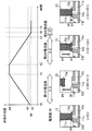
- FIG. 3 is a diagram showing an example of an opening / closing operation of the on-off valve 10 of FIG.
- the change over time in the position of the valve body 12a is shown graphically in the upper part of FIG.
- the vertical axis represents the relative position of the valve body 12a with respect to the valve seat 11s
- the horizontal axis represents time.
- advancing in the direction of the arrow means that the valve body 12a moves in the opening direction
- advancing in the direction opposite to the direction of the arrow means that the valve body 12a moves in the closing direction.
- the state inside the on-off valve 10 at a plurality of time points t0 to t5 shown in the upper graph is shown in a schematic cross-sectional view.
- the on-off valve 10 is in the closed state in the initial state at the time point t0.
- the initial position of the valve body 12a at this time is indicated by the symbol pp.
- the valve control unit 200 is instructed to switch the on-off valve 10 from the closed state to the open state when the supply of the resist liquid to the substrate W in the coating unit SC of FIG. 1 is started. Further, when the supply of the resist liquid to the substrate W in the coating unit SC is stopped, the on-off valve 10 is instructed to switch from the open state to the closed state.
- the setting storage unit 250 of FIG. 2 stores a preset number of drive pulses (hereinafter, referred to as open pulse number) m for switching the on-off valve 10 from the closed state to the open state.
- the number of open pulses m is, for example, 400.
- the setting storage unit 250 stores a first current value of a drive pulse preset for switching the on-off valve 10 from the closed state to the open state.
- the first current value is set so that the stepping motor 20 does not step out in consideration of the characteristics of the processing liquid (resist liquid in this example) flowing through the on-off valve 10 and the frictional force generated when the valve body 12a moves. It is set to a relatively large value (for example, 0.2 (A)).
- the pulse control unit 230 sends a drive pulse for moving the valve body 12a in the open direction to the stepping motor 20 by the number of open pulses m.
- the drive unit 40 is controlled so as to supply continuously.
- the current adjusting unit 240 controls the driving unit 40 so that the current value of the driving pulse becomes the first current value.
- the valve body 12a moves from the initial position pp to the position pa corresponding to the open state of the on-off valve 10 from the time point t0 to the time point t1.
- the resist liquid flows through the pipe p1 through the on-off valve 10.
- the setting storage unit 250 stores a preset number of drive pulses (hereinafter referred to as the number of closed pulses) n for switching the current value of the drive pulse when the on-off valve 10 is switched from the open state to the closed state.
- the number of closed pulses n is the number of open pulses m or less.
- the subtraction value (difference) of the number of closed pulses n with respect to the number of open pulses m is preferably 0 or more and 1/2 or less of the number of open pulses m, and preferably 0 or more and 10 or less.
- the number of closed pulses n may be, for example, 398.
- the setting storage unit 250 stores the second and third current values of the drive pulse set in advance for switching the on-off valve 10 from the closed state to the open state.
- the second current value corresponds to the drive pulse having the number of closed pulses n, and is a relatively large value (for example, 0.2 (A)) so that the stepping motor 20 does not step out like the first current value. ) Is set.
- the second current value may be equal to the first current value.
- the third current value is lower than the first and second current values (for example, 0) so that the pressing force acting on the valve seat 11s from the valve body 12a when the on-off valve 10 is closed does not become excessively large. It is set to .07 (A)).
- the pulse control unit 230 continuously sends a drive pulse for moving the valve body 12a in the closing direction to the stepping motor 20 by the number of closed pulses n.
- the drive unit 40 is controlled so as to supply.
- the current adjusting unit 240 controls the driving unit 40 so that the current value of the driving pulse becomes the second current value while the driving pulse having the number of closed pulses n is supplied to the stepping motor 20.
- the valve body 12a moves from the time point t2 to the time point t3 to the position bp deviated by a certain distance in the opening direction from the position pp.
- the current adjusting unit 240 controls the driving unit 40 so that the current value of the driving pulse becomes the third current value until the on-off valve 10 is closed.
- a preset number k for determining the completion of switching from the open state to the closed state of the on-off valve 10 is stored as a predetermined number.
- the switching determination unit 220 monitors the control state of the drive unit 40 by the pulse control unit 230, and also monitors the detection pulse output from the stepping motor 20. As a result of these monitoring, the switching determination unit 220 switches the on-off valve 10 to the closed state when the encoder 50 does not output a continuous detection pulse of a specified number of k in response to the supply of the continuous drive pulse. Determine that it is complete.
- the pulse control unit 230 stops the supply of the drive pulse from the drive unit 40 to the stepping motor 20.
- the stepping motor 20 Steps out.
- the stepping motor 20 is stepped out, the position of the valve body 12a fluctuates. It is difficult to grasp this amount of fluctuation. Therefore, the above-mentioned specified number k is set so as not to cause step-out of the stepping motor 20, and is 2 in this example.
- the rotation angle of the stepping motor 20 is maintained and the position of the valve body 12a is fixed.
- the valve body 12a is fixed at a position pc slightly deviated from the initial position pp in the closing direction. This means that the position of the valve body 12a when the on-off valve 10 is in the closed state has been changed to a more appropriate position pc than the position pp at the time point t0.
- the flow of the treatment liquid (resist liquid in this example) in the pipe p1 is appropriately blocked.
- the encoder 50 if it is not determined that the on-off valve 10 has been switched to the closed state due to continuous generation of noise having a waveform similar to the detection pulse, the supply of the drive pulse to the stepping motor 20 is stopped. Not done. In this case, step-out occurs in the stepping motor 20.
- the valve body 12a is detached from the valve rod 13
- the valve rod 13 moves beyond the position where it should be stopped and collides with the valve seat 11s.
- the abnormality determination unit 210 determines the occurrence of an abnormality when the continuous drive pulse supply is continued for a preset predetermined time when the on-off valve 10 is switched from the open state to the closed state.
- the abnormality determination unit 210 determines the occurrence of an abnormality, for example, when the supply of continuous drive pulses is continued for a predetermined time beyond a predetermined time from the time point t3. Further, the abnormality determination unit 210 outputs the determination result. In this case, it becomes possible to replace or maintain parts at an appropriate timing based on the determination of the occurrence of an abnormality.
- the processing liquid supply device 300 may be provided with a presentation device (display device, voice output device, etc.) that presents the abnormality determination result output from the abnormality determination unit 210 to the user.
- a presentation device display device, voice output device, etc.
- the user can easily grasp the occurrence of an abnormality in the on-off valve device V2.
- the processing liquid supply device corresponding to the developing unit SD of FIG. 1 has basically the same configuration and operation as the processing liquid supply device 300 of FIGS. 3 and 4.
- FIG. 4 is a flowchart showing an example of an opening / closing control process of the on-off valve 10 executed by the valve control unit 200 of FIG.
- the opening / closing control process is started when the valve control unit 200 is instructed to switch the opening / closing state of the on-off valve 10.
- the valve control unit 200 has a built-in counter. Further, it is assumed that the valve control unit 200 has a built-in timer.
- the pulse control unit 230 determines whether or not the command given at the start is a command for switching the on-off valve 10 from the open state to the closed state (step S11).
- the pulse control unit 230 and the current adjustment unit 240 continuously send the drive pulse having the number of closed pulses n to the stepping motor 20 at the second current value.
- the drive unit 40 is controlled so as to be supplied (step S12).
- the drive pulse supplied to the stepping motor 20 corresponds to the movement of the valve body 12a in the closing direction.
- the switching determination unit 220 resets the value of the counter and resets the timer, and starts the time measurement by the timer (step S13).
- the abnormality determination unit 210 determines whether or not a predetermined predetermined time has elapsed from the start of time measurement by the timer (step S14).
- the pulse control unit 230 and the current adjustment unit 240 are set so that one drive pulse is supplied to the stepping motor 20 at a third current value.
- the drive unit 40 is controlled (step S15). At this time, the drive pulse supplied to the stepping motor 20 corresponds to the movement of the valve body 12a in the closing direction.
- the switching determination unit 220 determines whether or not the detection pulse is output from the encoder 50 in response to the drive pulse supplied in step S15 (step S16). When the detection pulse is output, the process is returned from step S12 to step S14. On the other hand, when the detection pulse is not output, the switching determination unit 220 increments the counter value (step S17). Further, the switching determination unit 220 determines whether or not the detection pulse is not output for a specified number of k consecutive times based on the value of the counter (step S18).
- step S18 If the detection pulse is not output for a specified number of k consecutive times, the process is returned from step S18 to step S14. On the other hand, when the detection pulse is not output continuously for a specified number of k, the open / close control process ends in a state where the supply of the drive pulse to the stepping motor 20 is stopped.
- step S11 above when the command at the start is a command to switch to the open state, the pulse control unit 230 continuously supplies a drive pulse having an open pulse number of m to the stepping motor 20 at the first current value. As described above, the drive unit 40 is controlled (step S19). At this time, the drive pulse supplied to the stepping motor 20 corresponds to the movement of the valve body 12a in the opening direction. As a result, the valve body 12a moves in the opening direction with a relatively high torque. After that, the open / close control process ends.
- step S14 when a predetermined predetermined time has elapsed from the start of time measurement by the timer, the abnormality determination unit 210 determines the occurrence of an abnormality and outputs the determination result to the outside of the valve control unit 200. (Step S20). After that, the open / close control process ends.
- a drive pulse is continuously supplied to the stepping motor 20 when the on-off valve 10 is switched from the open state to the closed state.
- the valve body 12a moves toward the valve seat 11s.
- a detection pulse is output from the encoder 50 in response to the rotation of the stepping motor 20.
- valve body 12a When the reaction force acting on the valve body 12a from the valve seat 11s is balanced with the pressing force acting on the valve seat 11s from the valve body 12a in the state where the valve body 12a is in contact with the valve seat 11s, the valve body 12a is closed. The movement of the stepping motor 20 is stopped, and the rotation of the stepping motor 20 is stopped. Next, when the continuous specified number of detection pulses k to be output from the encoder 50 are no longer output, the supply of the drive pulse is stopped. As a result, the switching of the on-off valve 10 from the open state to the closed state is completed, and the flow of the processing liquid in the pipes p1 and p2 is stopped.
- valve body 12a is appropriately positioned with respect to the valve seat 11s in a state where the valve body 12a moves in the closing direction and stops. Therefore, it is not necessary to move the valve body 12a in the opening direction and the closing direction with respect to the valve seat 11s in order to search for the position of the valve body 12a to be positioned in the closed state.
- the current value of the drive pulse supplied to the stepping motor 20 is changed to the third current value until the supply of the drive pulse is stopped.
- the pressing force acting on the valve seat 11s from the valve body 12a in the closed state becomes excessively large.
- the on-off valve 10 in the processing liquid supply device 300 is used to switch between supplying and stopping the processing liquid (resist liquid, developing liquid, etc.) to the substrate W.
- the open / closed state of the above is switched, but the present invention is not limited to this.
- a command for switching the open / closed state of the on-off valve 10 may be given to the valve control unit 200 by the user operating an operation unit of the substrate processing device 100 (not shown).
- the user can instruct the switching operation of the on-off valve 10 similar to the example of FIG. 3 for the units (coating unit SC and developing unit SD in the above example) that supply the processing liquid to the substrate W. ..
- a series of operations for sequentially switching the on-off valve 10 in the closed state between the open state and the closed state may be automatically performed at a fixed cycle or at a predetermined number of lots. Alternatively, it may be automatically performed as an initialization operation of each unit (coating unit SC and developing unit SD in the above example) when the power of the substrate processing apparatus 100 is turned on.
- the treatment liquid supply device is applied to the resist liquid supply system that supplies the resist liquid to the substrate W and the developer supply system that supplies the developer liquid to the substrate W, respectively. Not limited to this.
- the treatment liquid supply device can be applied to a coating liquid supply system that supplies various coating liquids for forming an antireflection film, a resist cover film, or the like on a substrate W.
- the treatment liquid supply device according to the present invention can also be applied to a cleaning liquid supply system that supplies a cleaning liquid such as pure water or a chemical liquid to the substrate W.
- the rotary encoder is used as the encoder 50 for detecting the rotation of the stepping motor 20, but the present invention is not limited to this.
- the encoder 50 may be a linear encoder that detects the movement of the valve stem 13 in the opening direction and the closing direction. In this case, the movement of the valve stem 13 in the opening direction and the closing direction detected by the linear encoder can be detected as the rotation of the stepping motor 20.
- the current value of the drive pulse supplied to the stepping motor 20 when the on-off valve 10 is switched from the open state to the closed state is changed in two stages, but the present invention is limited to this. Not done.
- the current value of the drive pulse supplied to the stepping motor 20 when the on-off valve 10 is switched from the open state to the closed state may be constant.
- the current value is the above-mentioned third. It is desirable to set the current value of.
- the resist solution and the developing solution are examples of the processing solution
- the pipes p1 and p2 are examples of the processing solution flow path
- the valve control unit 200 is an example of the control unit
- the number of closed pulses is n.
- the time point when all the drive pulses are supplied to the stepping motor 20 (time point t3 in FIG. 3) is an example of the current switching time point.
Landscapes
- Engineering & Computer Science (AREA)
- Power Engineering (AREA)
- General Engineering & Computer Science (AREA)
- Mechanical Engineering (AREA)
- Electrically Driven Valve-Operating Means (AREA)
- Exposure Of Semiconductors, Excluding Electron Or Ion Beam Exposure (AREA)
- Control Of Stepping Motors (AREA)
Abstract
開閉弁の開状態から閉状態への切り替え時に、ステッピングモータに連続的に駆動パルスが供給される。駆動パルスに応答してステッピングモータが回転することにより、弁体が弁座に向かって移動する。ステッピングモータの回転に応答してエンコーダから検出パルスが出力される。ステッピングモータの回転が停止することにより、エンコーダから連続した規定数の検出パルスが出力されない場合に、駆動パルスの供給が停止される。この状態で、開閉弁における開状態から閉状態への切り替わりが完了する。
Description
本発明は、基板に処理液を供給する処理液供給装置および処理液供給装置の制御方法に関する。
従来より、液晶表示装置または有機EL(Electro Luminescence)表示装置等に用いられるFPD(Flat Panel Display)用基板、半導体基板、光ディスク用基板、磁気ディスク用基板、光磁気ディスク用基板、フォトマスク用基板、セラミック基板または太陽電池用基板等の各種基板に種々の処理を行うために、基板処理装置が用いられる。
基板処理装置においては、例えば処理液供給源から配管およびノズルを通して基板に処理液が供給される。配管には開閉弁が設けられる。その開閉弁は、ノズルから処理液を吐出させる開状態とノズルから処理液を吐出させない閉状態とに切り替えられる。
特許文献1には、上記の開閉弁を制御するための開閉弁制御装置が記載されている。その開閉弁制御装置においては、開閉弁の弁体が処理液の流路を閉塞する位置が閉止位置として設定される。設定された閉止位置に基づいて、ステッピングモータによる弁体の駆動が行われる。
閉止位置として適切な位置は、開閉弁を構成する各種部材の摩耗により変化する可能性がある。そこで、定期的かつ自動的に閉止位置の原点(基準)が設定される。この設定時には、まず、弁体を閉方向に駆動する駆動パルスがステッピングモータに与えられる。次に、ステッピングモータの脱調が検出された後、さらに弁体を閉方向に駆動する所定数の駆動パルスがステッピングモータに供給される。その後、弁体を開方向に駆動する既定数の駆動パルスがステッピングモータに供給される。このようにして、弁体の閉止位置の原点が検索されるとともに、検索された原点が設定される。
特開2004-348227号公報
上記のように、特許文献1に記載された閉止位置の原点検索方法においては、脱調の発生後、予め定められた数の駆動パルスがステッピングモータに供給される。このとき、ステッピングモータに流れる電流が大きいと、ステッピングモータに大きなトルクが発生し、弁体が弁座に強く押し付けられることになる。そのため、閉止位置の原点検索が頻繁に行われることにより、弁体と弁座との接触部に大きな変形が生じると、開閉弁が短寿命化し、パーティクルが発生する。
また、上記の原点検索方法においては、脱調を発生させた後さらに弁体を閉方向および開方向に移動させるために比較的長い時間を要する。
さらに、ステッピングモータは、脱調時にロータに作用するトルクが安定する安定点まで回転する。しかしながら、この回転量は常に一定量ではなく、正確に把握することは難しい。そのため、脱調の発生後に予め定められた数の駆動パルスでステッピングモータを動作させるだけでは、必ずしも適切な閉止位置が設定されるとは言い難い。
本発明の目的は、開閉弁の短寿命化を抑制しかつ長時間を要することなく開閉弁を適切に閉じることを可能にする処理液供給装置および処理液供給装置の制御方法を提供することである。
(1)本発明の一局面に従う処理液供給装置は、基板に処理液を供給する処理液供給装置であって、基板に供給されるべき処理液が流通する処理液流路と、弁座および弁体を含み、処理液流路に設けられる開閉弁と、開閉弁を開状態と閉状態とに切り替えるステッピングモータと、ステッピングモータに駆動パルスを供給する駆動部と、ステッピングモータの回転に応答して検出パルスを出力するエンコーダと、エンコーダにより出力される検出パルスに基づいて駆動部を制御する制御部とを含み、開閉弁は、開状態から閉状態への切り替わり時に、駆動部により供給される駆動パルスに応答してステッピングモータが回転することにより、弁体が弁座に向かって移動するように構成され、制御部は、開閉弁の開状態から閉状態への切り替え時に、ステッピングモータに連続的に駆動パルスが供給されるように駆動部を制御し、ステッピングモータへの連続的な駆動パルスの供給に応答してエンコーダから連続した規定数の検出パルスが出力されない場合に、駆動パルスの供給が停止されるように駆動部を制御する。
その処理液供給装置においては、開閉弁の開状態から閉状態への切り替え時に、ステッピングモータに連続的に駆動パルスが供給される。それにより、駆動パルスに応答してステッピングモータが回転することにより、弁体が弁座に向かって移動する。このとき、ステッピングモータの回転に応答してエンコーダから検出パルスが出力される。
その後、弁体が弁座に接触した状態で弁体から弁座に作用する押圧力に対して弁座から弁体に作用する反力が釣り合うと、弁体の動作が停止され、ステッピングモータの回転が停止する。さらに、エンコーダから出力されるべき連続した規定数の検出パルスが出力されなくなると、駆動パルスの供給が停止される。それにより、開状態から閉状態への開閉弁の切り替わりが完了し、処理液流路における処理液の流れが停止する。
この場合、ステッピングモータに脱調が生じない範囲で駆動パルスの供給が停止されることにより、開閉弁の開状態から閉状態への切り替え時に、開閉弁の内部で大きな負荷が発生することが抑制され、開閉弁内部の変形が抑制される。
また、上記の動作によれば、弁体が弁座に向かって一方向に移動して停止した状態で弁座に対する弁体の適切な位置決めが行われる。そのため、閉状態において位置決めされるべき弁体の位置を検索するために、弁座に対して弁体を上記の一方向およびその逆方向に移動させる必要がない。
さらに、上記の動作によれば、ステッピングモータを脱調させる必要がないので、脱調に起因して弁座に対する弁体の位置ずれが発生することが防止される。
これらの結果、開閉弁の短寿命化を抑制しかつ長時間を要することなく開閉弁を適切に閉じることが可能になる。
(2)制御部は、開状態における弁体の移動の開始時から駆動パルスの供給の停止時点よりも前の電流切替時点までに供給される駆動パルスの電流値が、電流切替時点から駆動パルスの供給の停止時点までに供給される駆動パルスの電流値よりも大きくなるように駆動部を制御してもよい。
この場合、弁体の移動開始時から電流切替時点までに供給される駆動パルスの電流値を大きくすることにより、弁体の移動のために必要なトルクを発生させることができる。それにより、開閉弁を流れる処理液の特性および弁体の動作時に発生する摩擦力等に起因する脱調の発生が防止される。
また、電流切替時点から駆動パルスの供給の停止時点までに供給される駆動パルスの電流値を小さくすることにより、閉状態で弁体から弁座に作用する押圧力が過剰に大きくなることが抑制される。それにより、弁体と弁座との接触部に大きな変形が生じることが防止されるとともに、当該接触部からパーティクルが発生することが低減される。
(3)制御部は、開閉弁の開状態から閉状態への切り替わり時に、ステッピングモータへの連続的な駆動パルスの供給が予め設定された時間継続された場合に異常の発生を判定してもよい。
この場合、異常の発生の判定に基づいて適切なタイミングで部品の交換またはメンテナンスを行うことが可能になる。
(4)本発明の他の局面に従う処理液供給装置の制御方法は、基板に処理液を供給する処理液供給装置の制御方法であって、処理液供給装置は、基板に供給されるべき処理液が流通する処理液流路と、弁座および弁体を含み、処理液流路に設けられる開閉弁と、開閉弁を開状態と閉状態とに切り替えるステッピングモータと、ステッピングモータに駆動パルスを供給する駆動部と、ステッピングモータの回転に応答して検出パルスを出力するエンコーダとを含み、開閉弁は、開状態から閉状態への切り替わり時に、駆動部により供給される駆動パルスに応答してステッピングモータが回転することにより、弁体が弁座に向かって移動するように構成され、制御方法は、開閉弁の開状態から閉状態への切り替え時に、ステッピングモータに連続的に駆動パルスが供給されるように駆動部を制御するステップと、ステッピングモータへの連続的な駆動パルスの供給に応答してエンコーダから連続した規定数の検出パルスが出力されない場合に、駆動パルスの供給が停止されるように駆動部を制御するステップとを含む。
その処理液供給装置の制御方法においては、開閉弁の開状態から閉状態への切り替え時に、ステッピングモータに連続的に駆動パルスが供給される。それにより、駆動パルスに応答してステッピングモータが回転することにより、弁体が弁座に向かって移動する。このとき、ステッピングモータの回転に応答してエンコーダから検出パルスが出力される。
その後、弁体が弁座に接触した状態で弁体から弁座に作用する押圧力に対して弁座から弁体に作用する反力が釣り合うと、弁体の動作が停止され、ステッピングモータの回転が停止する。さらに、エンコーダから出力されるべき連続した規定数の検出パルスが出力されなくなると、駆動パルスの供給が停止される。それにより、開状態から閉状態への開閉弁の切り替わりが完了し、処理液流路における処理液の流れが停止する。
この場合、ステッピングモータに脱調が生じない範囲で駆動パルスの供給が停止されることにより、開閉弁の開状態から閉状態への切り替え時に、開閉弁の内部で大きな負荷が発生することが抑制され、開閉弁内部の変形が抑制される。
また、上記の動作によれば、弁体が弁座に向かって一方向に移動して停止した状態で弁座に対する弁体の適切な位置決めが行われる。そのため、閉状態において位置決めされるべき弁体の位置を検索するために、弁座に対して弁体を上記の一方向およびその逆方向に移動させる必要がない。
さらに、上記の動作によれば、ステッピングモータを脱調させる必要がないので、脱調に起因して弁座に対する弁体の位置ずれが発生することが防止される。
これらの結果、開閉弁の短寿命化を抑制しかつ長時間を要することなく開閉弁を適切に閉じることが可能になる。
(5)処理液供給装置の制御方法は、開状態における弁体の移動の開始時から駆動パルスの供給の停止時点よりも前の電流切替時点までに供給される駆動パルスの電流値が、電流切替時点から駆動パルスの供給の停止時点までに供給される駆動パルスの電流値よりも大きくなるように駆動部を制御するステップをさらに含んでもよい。
この場合、弁体の移動開始時から電流切替時点までに供給される駆動パルスの電流値を大きくすることにより、弁体の移動のために必要なトルクを発生させることができる。それにより、開閉弁を流れる処理液の特性および弁体の動作時に発生する摩擦力等に起因する脱調の発生が防止される。
また、電流切替時点から駆動パルスの供給の停止時点までに供給される駆動パルスの電流値を小さくすることにより、閉状態で弁体から弁座に作用する押圧力が過剰に大きくなることが抑制される。それにより、弁体と弁座との接触部に大きな変形が生じることが防止されるとともに、当該接触部からパーティクルが発生することが低減される。
(6)処理液供給装置の制御方法は、開閉弁の開状態から閉状態への切り替わり時に、ステッピングモータへの連続的な駆動パルスの供給が予め設定された時間継続された場合に異常の発生を判定するステップをさらに含んでもよい。
この場合、異常の判定に基づいて適切なタイミングで開閉弁の交換またはメンテナンスを行うことが可能になる。
本発明によれば、開閉弁の短寿命化を抑制しかつ長時間を要することなく開閉弁を適切に閉じることが可能になる。
以下、本発明の実施の形態に係る処理液供給装置および処理液供給装置の制御方法について図面を参照しつつ説明する。以下の説明において、基板とは、液晶表示装置または有機EL(Electro Luminescence)表示装置等に用いられるFPD(Flat Panel Display)用基板、半導体基板、光ディスク用基板、磁気ディスク用基板、光磁気ディスク用基板、フォトマスク用基板、セラミック基板または太陽電池用基板等をいう。
(1)処理液供給装置を備える基板処理装置の構成
処理液供給装置を備える基板処理装置について説明する。図1は、本発明の一実施の形態に係る基板処理装置の構成を示す模式的ブロック図である。図1に示すように、基板処理装置100は、露光装置500に隣接して設けられ、塗布処理部110、現像処理部120、熱処理部130、搬送部140、制御装置150および複数の開閉弁装置V1,V2を備える。
処理液供給装置を備える基板処理装置について説明する。図1は、本発明の一実施の形態に係る基板処理装置の構成を示す模式的ブロック図である。図1に示すように、基板処理装置100は、露光装置500に隣接して設けられ、塗布処理部110、現像処理部120、熱処理部130、搬送部140、制御装置150および複数の開閉弁装置V1,V2を備える。
塗布処理部110は、複数の塗布ユニットSCを含む。各塗布ユニットSCは、スピンチャック91および吐出ノズル92を含む。スピンチャック91は、未処理の基板Wを水平姿勢で回転可能に保持する。吐出ノズル92には、基板処理装置100の外部に設けられる塗布液供給源1から、配管p1を通してレジスト液が供給される。吐出ノズル92は、供給されたレジスト液をスピンチャック91により保持された基板Wの上面に吐出する(塗布処理)。それにより、未処理の基板Wの一面上にレジスト膜が形成される。レジスト膜が形成された基板Wには、露光装置500において露光処理が行われる。
なお、塗布処理部110においては、基板Wに反射防止膜が形成されてもよい。この場合、熱処理部130は、基板Wと反射防止膜との密着性を向上させるための密着強化処理を行ってもよい。また、塗布処理部110においては、レジスト膜が形成された基板Wに、レジスト膜を保護するためのレジストカバー膜が形成されてもよい。
現像処理部120は、複数の現像ユニットSDを含む。各現像ユニットSDは、塗布ユニットSCと同様に、スピンチャック93および吐出ノズル94を含む。スピンチャック93は、露光装置500による露光処理後の基板Wを水平姿勢で回転可能に保持する。吐出ノズル94には、基板処理装置100の外部に設けられる現像液供給源2から、配管p2を通して現像液が供給される。吐出ノズル94は、供給された現像液をスピンチャック93により保持された基板Wの上面に吐出する(現像処理)。
熱処理部130は、塗布処理部110の各塗布ユニットSCによる塗布処理、現像処理部120による現像処理、および露光装置500による露光処理の前後に基板Wの熱処理を行う。
搬送部140は基板Wを搬送する搬送ロボットを有する。搬送部140の搬送ロボットは、基板Wを基板処理装置100の外部に設けられる他の搬送ロボット、塗布処理部110、現像処理部120、熱処理部130および露光装置500の間で搬送する。
制御装置150は、例えばCPUおよびメモリ、またはマイクロコンピュータを含み、塗布処理部110、現像処理部120、熱処理部130および搬送部140の動作を制御する。
塗布処理部110の複数の塗布ユニットSCと塗布液供給源1とをつなぐ複数の配管p1の各々には、基板Wに対するレジスト液の供給および停止を切り替えるための開閉弁装置V1が設けられている。また、現像処理部120の複数の現像ユニットSDと現像液供給源2とをつなぐ複数の配管p2の各々には、基板Wに対する現像液の供給および停止を切り替えるための開閉弁装置V2が設けられている。複数の開閉弁装置V1,V2の各々は、制御装置150の弁制御部200により制御される。
図1の基板処理装置100においては、各塗布ユニットSCに対応して設けられる配管p1および開閉弁装置V1と弁制御部200とが処理液供給装置を構成する。また、各現像ユニットSDに対応して設けられる配管p2および開閉弁装置V2と弁制御部200とが処理液供給装置を構成する。
(2)処理液供給装置の具体的な構成および動作
図2は、図1の塗布ユニットSCに対応する処理液供給装置の構成を説明するためのブロック図である。図2に示すように、処理液供給装置300は、配管p1、開閉弁装置V1および弁制御部200を備える。
図2は、図1の塗布ユニットSCに対応する処理液供給装置の構成を説明するためのブロック図である。図2に示すように、処理液供給装置300は、配管p1、開閉弁装置V1および弁制御部200を備える。
開閉弁装置V1は、開閉弁10、ステッピングモータ20、変換機構30、駆動部40およびエンコーダ50を含む。開閉弁10は、弁箱11を有する。弁箱11には、内部空間が形成されている。その内部空間の一部は、処理液(本例ではレジスト液)の流路を形成する流路空間11aとして、ダイアフラム12により区画されている。また、弁箱11には、流路空間11aに連通する流入ポート11bおよび流出ポート11cが設けられている。流入ポート11bおよび流出ポート11cに配管p1が接続されている。
ダイアフラム12は、例えばフッ化樹脂またはゴムにより形成されている。ダイアフラム12の中央部分は弁体12aとして機能する。弁箱11の内部には、流路空間11aを挟んで弁体12aに対向するように弁座11sが形成されている。弁座11sは、流路空間11a内の処理液(本例ではレジスト液)を流出ポート11cに導くための開口11oを有する。弁体12aが弁座11sに対して一方向またはその逆方向に移動することにより、開口11oの開閉が可能となっている。以下、弁体12aが弁座11sから離れた位置から弁座11sに向かって近づく方向を閉方向と呼び、その逆方向を開方向と呼ぶ。弁箱11の内部には、さらに弁棒13が設けられている。弁棒13は、弁体12aに接続されるとともに弁体12aから開方向に延びている。
本例のステッピングモータ20は、例えば二相型のステッピングモータであり、弁棒13により弁体12aを移動させて開閉弁10の開閉状態を切り替えるための動力源として用いられる。なお、ステッピングモータ20としては、三相型または五相型のステッピングモータが用いられてもよい。
変換機構30は、例えばラック&ピニオン機構を含み、ステッピングモータ20において発生される回転力を、弁棒13を閉方向または開方向に移動させる力に変換する。また、変換機構30は、弁棒13に対して閉方向または開方向に作用する力を、ステッピングモータ20の回転軸を一方向またはその逆方向に回転させる力に変換する。
駆動部40は、図示しない直流電源に接続され、後述する弁制御部200の制御に基づいてステッピングモータ20に駆動パルスを供給する。それにより、ステッピングモータ20は、供給された駆動パルスの数に応じた角度分一方向またはその逆方向に回転する。
エンコーダ50は、ロータリエンコーダであり、ステッピングモータ20のロータ(図示せず)の回転量を検出し、その検出信号としてパルス信号(以下、検出パルスと呼ぶ。)を出力する。例えば、一の駆動パルスがステッピングモータ20に供給されることによりステッピングモータ20がその駆動パルスに対応する角度分回転すると、エンコーダ50は一の検出パルスを出力する。一方、一の駆動パルスがステッピングモータ20に供給されても、ステッピングモータ20が回転しない場合、エンコーダ50は検出パルスを出力しない。
弁制御部200は、異常判定部210、切替判定部220、パルス制御部230、電流調整部240および設定記憶部250を含む。これらの機能部は、例えば図1の制御装置150のCPUがメモリに記憶されたコンピュータプログラムを実行することにより実現される。なお、上記の構成の一部または全てが電子回路等のハードウェアにより実現されてもよい。
弁制御部200の各機能部の動作について、開閉弁10における開閉動作とともに説明する。図3は、図2の開閉弁10における開閉動作の一例を示す図である。図3の上段に、弁体12aの位置の経時的な変化がグラフによって示される。図3の上段のグラフにおいては、縦軸が弁座11sに対する弁体12aの相対的な位置を表し、横軸は時間を表す。縦軸において、矢印の方向に進むことは弁体12aが開方向に移動することを意味し、矢印の方向と逆の方向に進むことは弁体12aが閉方向に移動することを意味する。図3の下段に、上段のグラフに示される複数の時点t0から時点t5における開閉弁10内部の状態が模式的断面図で示される。
本例では、時点t0の初期状態で開閉弁10が閉状態にあるものとする。このときの弁体12aの初期位置は符号ppで示される。弁制御部200には、図1の塗布ユニットSCにおける基板Wへのレジスト液の供給開始時に、開閉弁10の閉状態から開状態への切り替えが指令される。また、塗布ユニットSCにおける基板Wへのレジスト液の供給停止時に、開閉弁10の開状態から閉状態への切り替えが指令される。
図2の設定記憶部250には、開閉弁10を閉状態から開状態に切り替えるために予め設定された駆動パルスの数(以下、開パルス数と呼ぶ。)mが記憶されている。開パルス数mは例えば400である。また、設定記憶部250には、開閉弁10を閉状態から開状態に切り替えるために予め設定された駆動パルスの第1の電流値が記憶されている。第1の電流値は、開閉弁10を流れる処理液(本例ではレジスト液)の特性および弁体12aの移動時に発生する摩擦力を考慮して、ステッピングモータ20に脱調が生じないように比較的大きい値(例えば、0.2(A))に設定される。
図3の時点t0で開閉弁10の閉状態から開状態への切り替えが指令されると、パルス制御部230は、弁体12aを開方向へ移動させる駆動パルスをステッピングモータ20に開パルス数m連続的に供給するように駆動部40を制御する。また、電流調整部240は、駆動パルスの電流値が第1の電流値となるように駆動部40を制御する。
それにより、時点t0から時点t1にかけて弁体12aが初期の位置ppから開閉弁10の開状態に対応する位置paまで移動する。これにより、開閉弁10を通して配管p1をレジスト液が流通する。
設定記憶部250には、開閉弁10を開状態から閉状態に切り替える際に駆動パルスの電流値を切り替えるために予め設定された駆動パルスの数(以下、閉パルス数と呼ぶ。)nが記憶されている。閉パルス数nは、開パルス数m以下である。開パルス数mに対する閉パルス数nの減算値(差分)は、0以上かつ開パルス数mの1/2以下であることが好ましく、0以上かつ10以下であることが好ましい。開パルス数mが400である場合、閉パルス数nは例えば398であってもよい。
また、設定記憶部250には、開閉弁10を閉状態から開状態に切り替えるために予め設定された駆動パルスの第2および第3の電流値が記憶されている。第2の電流値は、閉パルス数nの駆動パルスに対応し、第1の電流値と同様にステッピングモータ20に脱調が生じないように比較的大きい値(例えば、0.2(A))に設定される。第2の電流値は第1の電流値と等しくてもよい。一方、第3の電流値は、開閉弁10の閉塞時に弁体12aから弁座11sに作用する押圧力が過剰に大きくならないように第1および第2の電流値よりも低い値(例えば、0.07(A))に設定される。
時点t2で開閉弁10の開状態から閉状態への切り替えが指令されると、パルス制御部230は、弁体12aを閉方向へ移動させる駆動パルスをステッピングモータ20に閉パルス数n連続的に供給するように駆動部40を制御する。また、電流調整部240は、閉パルス数nの駆動パルスがステッピングモータ20に供給される間、駆動パルスの電流値が第2の電流値となるように駆動部40を制御する。
それにより、閉パルス数nが開パルス数mよりも小さい場合には、時点t2から時点t3にかけて弁体12aが位置ppよりも開方向に一定距離ずれた位置pbまで移動する。
時点t3以降、電流調整部240は、開閉弁10が閉状態となるまでの間、駆動パルスの電流値が第3の電流値となるように駆動部40を制御する。
ステッピングモータ20が第3の電流値で駆動される際に、弁体12aから弁座11sに作用する押圧力に対して弁座11sから弁体12aに作用する反力が釣り合うと、弁体12aの閉方向への移動が停止される。それにより、駆動部40からステッピングモータ20に駆動パルスが供給される場合でも、エンコーダ50から検出パルスが出力されなくなる。
設定記憶部250には、開閉弁10における開状態から閉状態への切り替わりの完了を判定するために予め設定された数kが規定数として記憶されている。切替判定部220は、パルス制御部230による駆動部40の制御状態を監視するとともに、ステッピングモータ20から出力される検出パルスを監視する。これらの監視の結果、切替判定部220は、連続的な駆動パルスの供給に応答してエンコーダ50から連続した規定数kの検出パルスが出力されない場合に、開閉弁10の閉状態への切り替わりが完了したことを判定する。
パルス制御部230は、切替判定部220により開閉弁10の閉状態への切り替わりの完了が判定されると、駆動部40からステッピングモータ20への駆動パルスの供給を停止させる。
ここで、ステッピングモータ20の回転に対して弁体12aが停止した状態で、弁体12aが閉方向に移動するように所定数の駆動パルスがステッピングモータ20にさらに供給されると、ステッピングモータ20が脱調する。ステッピングモータ20の脱調時には、弁体12aの位置が変動する。この変動量を把握することは難しい。そこで、上記の規定数kは、ステッピングモータ20の脱調が生じないように定められ、本例では2である。
図3の例では、時点t3から時点t4にかけて、駆動パルスの供給に応答して弁体12aが閉方向に移動しているが、時点t4でその移動が停止している。その後、時点t5で、開閉弁10の閉状態へ切り替わりの完了が判定されている。
上記のようにして、開閉弁10の閉状態への切り替わりが完了すると、ステッピングモータ20の回転角度が保持され、弁体12aの位置が固定される。図3の例では、弁体12aは、初期の位置ppよりも閉方向にわずかにずれた位置pcで固定されている。このことは、開閉弁10が閉状態にあるときの弁体12aの位置が、時点t0の位置ppよりもより適切な位置pcに変更されたことを意味する。これにより、開閉弁10において配管p1における処理液(本例ではレジスト液)の流通が適切に遮断される。
開閉弁10が閉状態に切り替えられる際の一連の動作時には、開閉弁10、ステッピングモータ20およびエンコーダ50の何れかに異常が発生することにより、開閉弁10の閉状態への切り替えの完了を正確に判定できない可能性がある。
例えば、エンコーダ50において、検出パルスと同様の波形を有するノイズが継続的に発生することにより開閉弁10の閉状態への切り替えの完了が判定されないと、ステッピングモータ20への駆動パルスの供給が停止されない。この場合、ステッピングモータ20に脱調が発生する。あるいは、弁棒13から弁体12aが外れていると、弁棒13が本来停止されるべき位置を超えて移動し、弁座11sに衝突する。
そこで、異常判定部210は、開閉弁10の開状態から閉状態への切り替わり時に、連続的な駆動パルスの供給が予め設定された規定時間継続された場合に、異常の発生を判定する。図3の例では、異常判定部210は、例えば時点t3から連続的な駆動パルスの供給が予め定められた規定時間を超えて継続された場合に、異常の発生を判定する。また、異常判定部210は、その判定結果を出力する。この場合、異常の発生の判定に基づいて適切なタイミングで部品の交換またはメンテナンスを行うことが可能になる。
なお、処理液供給装置300には、異常判定部210から出力される異常の判定結果を使用者に提示する提示装置(表示装置または音声出力装置等)が設けられてもよい。この場合、使用者は、開閉弁装置V2における異常の発生を容易に把握することができる。
図1の現像ユニットSDに対応する処理液供給装置は、図3および図4の処理液供給装置300と基本的に同じ構成および動作を有する。
(3)開閉弁10の開閉制御処理
図4は、図2の弁制御部200において実行される開閉弁10の開閉制御処理の一例を示すフローチャートである。開閉制御処理は、弁制御部200に開閉弁10の開閉状態の切り換えの指令が与えられることにより開始される。以下の説明において、弁制御部200には、カウンタが内蔵されているものとする。また、弁制御部200には、タイマが内蔵されているものとする。
図4は、図2の弁制御部200において実行される開閉弁10の開閉制御処理の一例を示すフローチャートである。開閉制御処理は、弁制御部200に開閉弁10の開閉状態の切り換えの指令が与えられることにより開始される。以下の説明において、弁制御部200には、カウンタが内蔵されているものとする。また、弁制御部200には、タイマが内蔵されているものとする。
まず、パルス制御部230は、開始時に与えられた指令が、開閉弁10を開状態から閉状態に切り換える指令であるか否かを判定する(ステップS11)。
開始時の指令が開状態から閉状態への切り替え指令である場合、パルス制御部230および電流調整部240は、閉パルス数nの駆動パルスが第2の電流値でステッピングモータ20に連続的に供給されるように、駆動部40を制御する(ステップS12)。このときステッピングモータ20に供給される駆動パルスは、弁体12aの閉方向の移動に対応する。それにより、弁体12aが比較的高いトルクで閉方向に移動する。また、切替判定部220は、カウンタの値をリセットするとともにタイマをリセットし、タイマによる時間計測を開始する(ステップS13)。
次に、異常判定部210は、タイマによる時間計測開始から予め定められた規定時間が経過したか否かを判定する(ステップS14)。タイマによる時間計測開始時点から予め定められた規定時間が経過していない場合、パルス制御部230および電流調整部240は、一の駆動パルスが第3の電流値でステッピングモータ20に供給されるように、駆動部40を制御する(ステップS15)。このときステッピングモータ20に供給される駆動パルスは、弁体12aの閉方向の移動に対応する。
次に、切替判定部220は、ステップS15で供給された駆動パルスに応答してエンコーダ50から検出パルスが出力されたか否かを判定する(ステップS16)。検出パルスが出力された場合、処理はステップS12からステップS14に戻される。一方、検出パルスが出力されない場合、切替判定部220は、カウンタの値をインクリメントする(ステップS17)。また、切替判定部220は、カウンタの値に基づいて検出パルスが出力されないことが規定数k連続したか否かを判定する(ステップS18)。
検出パルスが出力されないことが規定数k連続していない場合、処理はステップS18からステップS14に戻される。一方、検出パルスが出力されないことが規定数k連続した場合、ステッピングモータ20への駆動パルスの供給が停止された状態で開閉制御処理が終了する。
上記のステップS11において、開始時の指令が開状態に切り換える指令である場合、パルス制御部230は、開パルス数mの駆動パルスが第1の電流値でステッピングモータ20に連続的に供給されるように、駆動部40を制御する(ステップS19)。このときステッピングモータ20に供給される駆動パルスは、弁体12aの開方向の移動に対応する。それにより、弁体12aが比較的高いトルクで開方向に移動する。その後、開閉制御処理が終了する。
上記のステップS14において、タイマによる時間計測開始から予め定められた規定時間が経過していた場合、異常判定部210は、異常の発生を判定し、その判定結果を弁制御部200の外部に出力する(ステップS20)。その後、開閉制御処理が終了する。
(4)効果
(a)上記の処理液供給装置300においては、開閉弁10の開状態から閉状態への切り替え時に、ステッピングモータ20に連続的に駆動パルスが供給される。駆動パルスに応答してステッピングモータ20が回転することにより、弁体12aが弁座11sに向かって移動する。このとき、ステッピングモータ20の回転に応答してエンコーダ50から検出パルスが出力される。
(a)上記の処理液供給装置300においては、開閉弁10の開状態から閉状態への切り替え時に、ステッピングモータ20に連続的に駆動パルスが供給される。駆動パルスに応答してステッピングモータ20が回転することにより、弁体12aが弁座11sに向かって移動する。このとき、ステッピングモータ20の回転に応答してエンコーダ50から検出パルスが出力される。
弁体12aが弁座11sに接触した状態で弁体12aから弁座11sに作用する押圧力に対して弁座11sから弁体12aに作用する反力が釣り合うと、弁体12aの閉方向への移動が停止され、ステッピングモータ20の回転が停止する。次に、エンコーダ50から出力されるべき連続した規定数kの検出パルスが出力されなくなると、駆動パルスの供給が停止される。それにより、開状態から閉状態への開閉弁10の切り替わりが完了し、配管p1,p2における処理液の流れが停止する。
この場合、ステッピングモータ20に脱調が生じない範囲で駆動パルスの供給が停止されることにより、開閉弁10の開閉状態の切り替え時に、開閉弁10の内部で大きな負荷が発生することが抑制される。それにより、開閉弁10内部の変形が抑制される。
また、上記の動作によれば、弁体12aが閉方向に移動して停止した状態で弁座11sに対する弁体12aの適切な位置決めが行われる。そのため、閉状態において位置決めされるべき弁体12aの位置を検索するために、弁座11sに対して弁体12aを開方向および閉方向にそれぞれ移動させる必要がない。
さらに、上記の動作によれば、ステッピングモータ20を脱調させる必要がないので、脱調に起因して弁座11sに対する弁体12aの位置ずれが発生することが防止される。
これらの結果、開閉弁10の短寿命化を抑制しかつ長時間を要することなく開閉弁10を適切に閉じることが可能になる。
(b)上記の処理液供給装置300においては、開閉弁10の開状態から閉状態への切り替え時に、閉パルス数nの駆動パルスがステッピングモータ20に供給される間、ステッピングモータ20は第2の電流値で駆動される。それにより、開閉弁を流れる処理液の特性および弁体12aの動作時に発生する摩擦力等に起因する脱調の発生が防止される。
その後、駆動パルスの供給の停止までの間、ステッピングモータ20に供給される駆動パルスの電流値が第3の電流値に変更される。この場合、閉状態で弁体12aから弁座11sに作用する押圧力が過剰に大きくなることが抑制される。それにより、弁体12aと弁座11sとの接触部に大きな変形が生じることが防止されるとともに、当該接触部からパーティクルが発生することが低減される。
(5)他の実施の形態
(a)上記実施の形態においては、基板Wへの処理液(レジスト液または現像液等)の供給および停止を切り替える際に、処理液供給装置300における開閉弁10の開閉状態の切り替えが行われるが、本発明はこれに限定されない。
(a)上記実施の形態においては、基板Wへの処理液(レジスト液または現像液等)の供給および停止を切り替える際に、処理液供給装置300における開閉弁10の開閉状態の切り替えが行われるが、本発明はこれに限定されない。
開閉弁10の開閉状態の切り替えの指令は、使用者が図示しない基板処理装置100の操作部を操作することにより弁制御部200に与えられてもよい。この場合、使用者は、基板Wに処理液を供給するユニット(上記の例では塗布ユニットSCおよび現像ユニットSD)について、図3の例と同様の開閉弁10の切り替え動作を指令することができる。
また、図3に示されるように、閉状態にある開閉弁10を開状態および閉状態に順次切り替える一連の動作は、一定周期あるいは所定数のロットごとに自動的に行われてもよい。あるいは、基板処理装置100の電源投入時に各ユニット(上記の例では塗布ユニットSCおよび現像ユニットSD)の初期化動作として自動的に行われてもよい。
(b)上記実施の形態においては、基板Wにレジスト液を供給するレジスト液供給系および基板Wに現像液を供給する現像液供給系にそれぞれ処理液供給装置が適用されるが、本発明はこれに限定されない。
本発明に係る処理液供給装置は、基板Wに反射防止膜またはレジストカバー膜等を形成するための各種塗布液を供給する塗布液供給系に適用することができる。あるいは、本発明に係る処理液供給装置は、基板Wに純水または薬液等の洗浄液を供給する洗浄液供給系に適用することもできる。
(c)上記実施の形態においては、ステッピングモータ20の回転を検出するためのエンコーダ50としてロータリエンコーダが用いられるが、本発明はこれに限定されない。エンコーダ50は、弁棒13の開方向および閉方向への移動を検出するリニアエンコーダであってもよい。この場合、リニアエンコーダにより検出される弁棒13の開方向および閉方向への移動を、ステッピングモータ20の回転として検出することができる。
(d)上記実施の形態においては、開閉弁10の開状態から閉状態への切り替え時にステッピングモータ20に供給される駆動パルスの電流値が2段階に変更されるが、本発明はこれに限定されない。開閉弁10の開状態から閉状態への切り替え時にステッピングモータ20に供給される駆動パルスの電流値は一定であってもよい。処理液の粘度が低いこと、または弁棒13の動作時に発生する摩擦力が小さいこと等の理由により弁棒13を移動させるために必要なトルクが十分小さい場合、その電流値は上記の第3の電流値に設定されることが望ましい。
(6)請求項の各構成要素と実施の形態の各要素との対応関係
以下、請求項の各構成要素と実施の形態の各要素との対応の例について説明する。上記実施の形態では、レジスト液および現像液が処理液の例であり、配管p1,p2が処理液流路の例であり、弁制御部200が制御部の例であり、閉パルス数nの駆動パルスが全てステッピングモータ20に供給された時点(図3の時点t3)が電流切替時点の例である。
以下、請求項の各構成要素と実施の形態の各要素との対応の例について説明する。上記実施の形態では、レジスト液および現像液が処理液の例であり、配管p1,p2が処理液流路の例であり、弁制御部200が制御部の例であり、閉パルス数nの駆動パルスが全てステッピングモータ20に供給された時点(図3の時点t3)が電流切替時点の例である。
請求項の各構成要素として、請求項に記載されている構成または機能を有する他の種々の要素を用いることもできる。
Claims (6)
- 基板に処理液を供給する処理液供給装置であって、
基板に供給されるべき処理液が流通する処理液流路と、
弁座および弁体を含み、前記処理液流路に設けられる開閉弁と、
前記開閉弁を開状態と閉状態とに切り替えるステッピングモータと、
前記ステッピングモータに駆動パルスを供給する駆動部と、
前記ステッピングモータの回転に応答して検出パルスを出力するエンコーダと、
前記エンコーダにより出力される検出パルスに基づいて前記駆動部を制御する制御部とを含み、
前記開閉弁は、前記開状態から前記閉状態への切り替わり時に、前記駆動部により供給される前記駆動パルスに応答して前記ステッピングモータが回転することにより、前記弁体が前記弁座に向かって移動するように構成され、
前記制御部は、前記開閉弁の前記開状態から前記閉状態への切り替え時に、前記ステッピングモータに連続的に前記駆動パルスが供給されるように前記駆動部を制御し、前記ステッピングモータへの連続的な前記駆動パルスの供給に応答して前記エンコーダから連続した規定数の検出パルスが出力されない場合に、前記駆動パルスの供給が停止されるように前記駆動部を制御する、処理液供給装置。 - 前記制御部は、前記開状態における前記弁体の移動の開始時から前記駆動パルスの供給の停止時点よりも前の電流切替時点までに供給される前記駆動パルスの電流値が、前記電流切替時点から前記駆動パルスの供給の停止時点までに供給される前記駆動パルスの電流値よりも大きくなるように前記駆動部を制御する、請求項1記載の処理液供給装置。
- 前記制御部は、前記開閉弁の前記開状態から前記閉状態への切り替わり時に、前記ステッピングモータへの連続的な前記駆動パルスの供給が予め設定された時間継続された場合に異常の発生を判定する、請求項1または2記載の処理液供給装置。
- 基板に処理液を供給する処理液供給装置の制御方法であって、
前記処理液供給装置は、
基板に供給されるべき処理液が流通する処理液流路と、
弁座および弁体を含み、前記処理液流路に設けられる開閉弁と、
前記開閉弁を開状態と閉状態とに切り替えるステッピングモータと、
前記ステッピングモータに駆動パルスを供給する駆動部と、
前記ステッピングモータの回転に応答して検出パルスを出力するエンコーダとを含み、
前記開閉弁は、前記開状態から前記閉状態への切り替わり時に、前記駆動部により供給される前記駆動パルスに応答して前記ステッピングモータが回転することにより、前記弁体が前記弁座に向かって移動するように構成され、
前記制御方法は、
前記開閉弁の前記開状態から前記閉状態への切り替え時に、前記ステッピングモータに連続的に前記駆動パルスが供給されるように前記駆動部を制御するステップと、
前記ステッピングモータへの連続的な前記駆動パルスの供給に応答して前記エンコーダから連続した規定数の検出パルスが出力されない場合に、前記駆動パルスの供給が停止されるように前記駆動部を制御するステップとを含む、処理液供給装置の制御方法。 - 前記開状態における前記弁体の移動の開始時から前記駆動パルスの供給の停止時点よりも前の電流切替時点までに供給される前記駆動パルスの電流値が、前記電流切替時点から前記駆動パルスの供給の停止時点までに供給される前記駆動パルスの電流値よりも大きくなるように前記駆動部を制御するステップをさらに含む、請求項4記載の処理液供給装置の制御方法。
- 前記開閉弁の前記開状態から前記閉状態への切り替わり時に、前記ステッピングモータへの連続的な前記駆動パルスの供給が予め設定された時間継続された場合に異常の発生を判定するステップをさらに含む、請求項4または5記載の処理液供給装置の制御方法。
Priority Applications (2)
| Application Number | Priority Date | Filing Date | Title |
|---|---|---|---|
| CN202080019247.1A CN113544419B (zh) | 2019-03-20 | 2020-02-04 | 处理液供给装置及处理液供给装置的控制方法 |
| KR1020217029172A KR102548556B1 (ko) | 2019-03-20 | 2020-02-04 | 처리액 공급 장치 및 처리액 공급 장치의 제어 방법 |
Applications Claiming Priority (2)
| Application Number | Priority Date | Filing Date | Title |
|---|---|---|---|
| JP2019053369A JP7223609B2 (ja) | 2019-03-20 | 2019-03-20 | 処理液供給装置および処理液供給装置の制御方法 |
| JP2019-053369 | 2019-03-20 |
Publications (1)
| Publication Number | Publication Date |
|---|---|
| WO2020189059A1 true WO2020189059A1 (ja) | 2020-09-24 |
Family
ID=72519249
Family Applications (1)
| Application Number | Title | Priority Date | Filing Date |
|---|---|---|---|
| PCT/JP2020/004186 Ceased WO2020189059A1 (ja) | 2019-03-20 | 2020-02-04 | 処理液供給装置および処理液供給装置の制御方法 |
Country Status (5)
| Country | Link |
|---|---|
| JP (1) | JP7223609B2 (ja) |
| KR (1) | KR102548556B1 (ja) |
| CN (1) | CN113544419B (ja) |
| TW (1) | TWI750579B (ja) |
| WO (1) | WO2020189059A1 (ja) |
Families Citing this family (3)
| Publication number | Priority date | Publication date | Assignee | Title |
|---|---|---|---|---|
| JP7671663B2 (ja) * | 2021-09-24 | 2025-05-02 | 株式会社Screenホールディングス | 基板処理装置 |
| CN116201942A (zh) * | 2023-02-15 | 2023-06-02 | 西安航天远征流体控制股份有限公司 | 利用步进电机作为驱动源的阀门控制系统及其控制方法 |
| CN116274143B (zh) * | 2023-03-23 | 2025-08-08 | 上海琥崧智能科技股份有限公司 | 一种适用于新能源负极行业产线二次除尘风管的设备 |
Citations (5)
| Publication number | Priority date | Publication date | Assignee | Title |
|---|---|---|---|---|
| JP2004327775A (ja) * | 2003-04-25 | 2004-11-18 | Dainippon Screen Mfg Co Ltd | 基板処理装置および吐出制御方法 |
| JP2005054954A (ja) * | 2003-08-07 | 2005-03-03 | Tokyo Keiso Co Ltd | コントロール弁 |
| JP2005351308A (ja) * | 2004-06-08 | 2005-12-22 | Ckd Corp | 流体制御弁の制御方法 |
| JP2006170361A (ja) * | 2004-12-17 | 2006-06-29 | Arumo Technos Kk | 弁装置 |
| JP2017194080A (ja) * | 2016-04-18 | 2017-10-26 | 株式会社Screenホールディングス | 処理液供給装置およびその制御方法 |
Family Cites Families (20)
| Publication number | Priority date | Publication date | Assignee | Title |
|---|---|---|---|---|
| US3324770A (en) * | 1965-06-11 | 1967-06-13 | Corning Glass Works | Control system |
| JPS61189379A (ja) * | 1985-02-18 | 1986-08-23 | Mitsubishi Heavy Ind Ltd | 油圧制御装置の性能試験方法 |
| JPH03282077A (ja) * | 1990-03-28 | 1991-12-12 | Honda Motor Co Ltd | スロットルバルブ開度検出器の基準位置設定方法 |
| JPH04295908A (ja) * | 1991-03-25 | 1992-10-20 | Sekisui Chem Co Ltd | 電動バルブの位置決め制御装置 |
| JP2755171B2 (ja) * | 1994-06-13 | 1998-05-20 | 松下電器産業株式会社 | 流体制御装置 |
| US5844394A (en) * | 1996-09-20 | 1998-12-01 | Matsushita Electric Industrial Co., Ltd. | Stepping motor controller |
| JP4103388B2 (ja) * | 2001-12-28 | 2008-06-18 | 松下電器産業株式会社 | 流体制御装置 |
| KR100484937B1 (ko) * | 2002-09-17 | 2005-04-22 | 삼성전자주식회사 | 냉장고의 밸브불량 판정방법 |
| JP4311981B2 (ja) | 2003-05-20 | 2009-08-12 | 東京計装株式会社 | バルブ制御装置およびその原点検索方法 |
| JP2009127347A (ja) * | 2007-11-27 | 2009-06-11 | Panasonic Electric Works Co Ltd | 自動ドア駆動装置及び自動ドア装置 |
| KR101040133B1 (ko) | 2010-12-30 | 2011-06-09 | 민성기 | 밸브 액츄에이터 제어 시스템 |
| GB2496909A (en) | 2011-11-28 | 2013-05-29 | Eaton Aerospace Ltd | Valve actuator |
| JP6101511B2 (ja) * | 2013-02-19 | 2017-03-22 | 株式会社不二工機 | ステッピングモータ及びそれを用いた電動弁 |
| JP6563213B2 (ja) * | 2015-02-24 | 2019-08-21 | 株式会社不二工機 | 電動弁及びその組立方法 |
| JP6512894B2 (ja) * | 2015-03-27 | 2019-05-15 | 株式会社Screenホールディングス | 処理液供給装置および処理液供給装置の制御方法 |
| KR101600346B1 (ko) | 2015-10-30 | 2016-03-07 | 이순학 | 엑츄에이터 컨트롤 장치 |
| JP6583128B2 (ja) * | 2016-04-28 | 2019-10-02 | トヨタ紡織株式会社 | 乗物用シート |
| AU2017287708A1 (en) | 2016-06-30 | 2019-01-31 | Ivex Pty Ltd | A valve controller |
| CN106941332A (zh) * | 2016-12-20 | 2017-07-11 | 广西风华服饰有限责任公司 | 一种缝纫机步进电机控制方法及控制系统 |
| KR102178555B1 (ko) * | 2018-11-19 | 2020-11-13 | (주)지니스 | Bldc 모터 제어장치 |
-
2019
- 2019-03-20 JP JP2019053369A patent/JP7223609B2/ja active Active
-
2020
- 2020-02-04 KR KR1020217029172A patent/KR102548556B1/ko active Active
- 2020-02-04 WO PCT/JP2020/004186 patent/WO2020189059A1/ja not_active Ceased
- 2020-02-04 CN CN202080019247.1A patent/CN113544419B/zh active Active
- 2020-02-06 TW TW109103631A patent/TWI750579B/zh active
Patent Citations (5)
| Publication number | Priority date | Publication date | Assignee | Title |
|---|---|---|---|---|
| JP2004327775A (ja) * | 2003-04-25 | 2004-11-18 | Dainippon Screen Mfg Co Ltd | 基板処理装置および吐出制御方法 |
| JP2005054954A (ja) * | 2003-08-07 | 2005-03-03 | Tokyo Keiso Co Ltd | コントロール弁 |
| JP2005351308A (ja) * | 2004-06-08 | 2005-12-22 | Ckd Corp | 流体制御弁の制御方法 |
| JP2006170361A (ja) * | 2004-12-17 | 2006-06-29 | Arumo Technos Kk | 弁装置 |
| JP2017194080A (ja) * | 2016-04-18 | 2017-10-26 | 株式会社Screenホールディングス | 処理液供給装置およびその制御方法 |
Also Published As
| Publication number | Publication date |
|---|---|
| JP2020155620A (ja) | 2020-09-24 |
| CN113544419A (zh) | 2021-10-22 |
| TW202040632A (zh) | 2020-11-01 |
| TWI750579B (zh) | 2021-12-21 |
| CN113544419B (zh) | 2024-01-23 |
| JP7223609B2 (ja) | 2023-02-16 |
| KR102548556B1 (ko) | 2023-06-27 |
| KR20210124449A (ko) | 2021-10-14 |
Similar Documents
| Publication | Publication Date | Title |
|---|---|---|
| TWI750579B (zh) | 處理液供給裝置及處理液供給裝置之控制方法 | |
| JP2010123709A (ja) | 基板処理装置 | |
| WO2007114603A1 (en) | Photoresist coating apparatus having nozzle monitoring unit and method for suppling photoresist using the same | |
| JP2001110712A5 (ja) | ||
| JP2018041754A5 (ja) | ||
| JP4316921B2 (ja) | 基板処理装置 | |
| JP4776409B2 (ja) | 電動バルブ | |
| US20160116845A1 (en) | Liquid delivery method, liquid delivery system, and computer-readable storage medium | |
| US20230205235A1 (en) | Apparatus for treating substrate and method for treating a substrate | |
| WO2007004485A1 (ja) | 洗浄装置および洗浄方法 | |
| JP4202176B2 (ja) | 基板処理装置および吐出制御方法 | |
| JP4311981B2 (ja) | バルブ制御装置およびその原点検索方法 | |
| JP6709668B2 (ja) | 処理液供給装置およびその制御方法 | |
| TW202538190A (zh) | 基板處理裝置 | |
| JP4202177B2 (ja) | 基板処理装置および基板処理方法 | |
| KR101776021B1 (ko) | 기판 처리 장치 및 기판 처리 방법 | |
| WO2005090001A1 (ja) | 液体供給装置、研磨装置及び半導体デバイス製造方法 | |
| JP4382595B2 (ja) | 粘性流体供給装置及びその固化防止方法 | |
| JP7847112B2 (ja) | 基板処理方法および基板処理装置 | |
| KR101909187B1 (ko) | 기판 처리 장치 및 약액 모니터링 방법 | |
| JP4917624B2 (ja) | 粘性流体供給装置及びその固化防止方法並びにプログラム | |
| KR20200019018A (ko) | 유량제어시스템 | |
| JP2019124279A (ja) | 切替弁および塗布装置 | |
| JP2003029847A (ja) | 流量制御弁装置 | |
| EP3678290A1 (en) | Motor driving device |
Legal Events
| Date | Code | Title | Description |
|---|---|---|---|
| 121 | Ep: the epo has been informed by wipo that ep was designated in this application |
Ref document number: 20773847 Country of ref document: EP Kind code of ref document: A1 |
|
| ENP | Entry into the national phase |
Ref document number: 20217029172 Country of ref document: KR Kind code of ref document: A |
|
| NENP | Non-entry into the national phase |
Ref country code: DE |
|
| 122 | Ep: pct application non-entry in european phase |
Ref document number: 20773847 Country of ref document: EP Kind code of ref document: A1 |