WO2020188760A1 - ヘッドマウントディスプレイ - Google Patents
ヘッドマウントディスプレイ Download PDFInfo
- Publication number
- WO2020188760A1 WO2020188760A1 PCT/JP2019/011518 JP2019011518W WO2020188760A1 WO 2020188760 A1 WO2020188760 A1 WO 2020188760A1 JP 2019011518 W JP2019011518 W JP 2019011518W WO 2020188760 A1 WO2020188760 A1 WO 2020188760A1
- Authority
- WO
- WIPO (PCT)
- Prior art keywords
- head
- mounted display
- display according
- circuit board
- main body
- Prior art date
- Legal status (The legal status is an assumption and is not a legal conclusion. Google has not performed a legal analysis and makes no representation as to the accuracy of the status listed.)
- Ceased
Links
Images






Classifications
-
- G—PHYSICS
- G02—OPTICS
- G02B—OPTICAL ELEMENTS, SYSTEMS OR APPARATUS
- G02B7/00—Mountings, adjusting means, or light-tight connections, for optical elements
- G02B7/008—Mountings, adjusting means, or light-tight connections, for optical elements with means for compensating for changes in temperature or for controlling the temperature; thermal stabilisation
-
- G—PHYSICS
- G02—OPTICS
- G02B—OPTICAL ELEMENTS, SYSTEMS OR APPARATUS
- G02B27/00—Optical systems or apparatus not provided for by any of the groups G02B1/00 - G02B26/00, G02B30/00
- G02B27/01—Head-up displays
- G02B27/017—Head mounted
- G02B27/0172—Head mounted characterised by optical features
-
- G—PHYSICS
- G02—OPTICS
- G02B—OPTICAL ELEMENTS, SYSTEMS OR APPARATUS
- G02B27/00—Optical systems or apparatus not provided for by any of the groups G02B1/00 - G02B26/00, G02B30/00
- G02B27/01—Head-up displays
- G02B27/017—Head mounted
- G02B27/0176—Head mounted characterised by mechanical features
-
- G—PHYSICS
- G06—COMPUTING OR CALCULATING; COUNTING
- G06F—ELECTRIC DIGITAL DATA PROCESSING
- G06F1/00—Details not covered by groups G06F3/00 - G06F13/00 and G06F21/00
- G06F1/16—Constructional details or arrangements
- G06F1/1613—Constructional details or arrangements for portable computers
- G06F1/163—Wearable computers, e.g. on a belt
-
- G—PHYSICS
- G06—COMPUTING OR CALCULATING; COUNTING
- G06F—ELECTRIC DIGITAL DATA PROCESSING
- G06F1/00—Details not covered by groups G06F3/00 - G06F13/00 and G06F21/00
- G06F1/16—Constructional details or arrangements
- G06F1/20—Cooling means
-
- G—PHYSICS
- G06—COMPUTING OR CALCULATING; COUNTING
- G06F—ELECTRIC DIGITAL DATA PROCESSING
- G06F1/00—Details not covered by groups G06F3/00 - G06F13/00 and G06F21/00
- G06F1/16—Constructional details or arrangements
- G06F1/20—Cooling means
- G06F1/203—Cooling means for portable computers, e.g. for laptops
-
- G—PHYSICS
- G02—OPTICS
- G02B—OPTICAL ELEMENTS, SYSTEMS OR APPARATUS
- G02B27/00—Optical systems or apparatus not provided for by any of the groups G02B1/00 - G02B26/00, G02B30/00
- G02B27/01—Head-up displays
- G02B27/0101—Head-up displays characterised by optical features
- G02B2027/0138—Head-up displays characterised by optical features comprising image capture systems, e.g. camera
Definitions
- the present invention relates to a head-mounted display.
- the head-mounted display includes a device main body in which the display is built, and a band that supports the device main body and surrounds the user's head.
- Patent Document 1 discloses a head-mounted display provided with a heat pipe and a fan in order to suppress an increase in temperature of electronic components.
- the cooling device is provided in the front portion of the device main body of the head-mounted display as disclosed in Patent Document 1, the center of gravity of the device main body is located in the front, which affects the user who wears the head-mounted display. The load will increase.
- One of the purposes of the present specification is to provide a head-mounted display that suppresses an excessive rise in the temperature of electronic components and reduces the load on the user.
- An example of the head-mounted display proposed in the present disclosure includes a device main body, a mounting band that supports the device main body and is attached to the user's head, and one or more head-mounted displays that are arranged on the upper part of the device main body. It has a circuit board having a mounting surface on which electronic components are mounted, and a cooling device arranged above the device main body so as to face the mounting surface.
- the head-mounted display it is possible to suppress an excessive rise in the temperature of electronic components and reduce the load on the user.
- FIG. 1 It is a figure which shows the use state of the HMD which concerns on this embodiment. It is a perspective view which looked at the internal structure of the apparatus main body of this embodiment from the diagonally left front. It is an exploded perspective view which shows the internal structure and the mounting band of the apparatus main body of this embodiment. It is the top view which looked at the internal structure of the apparatus main body of this embodiment from above. It is a side view which looked at the internal structure of the apparatus main body of this embodiment from the left. It is a front view which looked at the internal structure of the apparatus main body of this embodiment from the front. It is a perspective view which shows the cooling apparatus and a circuit board of this embodiment. It is a top view which shows the cooling apparatus and a circuit board of this embodiment.
- the directions indicated by X1 and X2 in the figure are defined as right and left
- the directions indicated by Y1 and Y2 in the figure are defined as front and rear, respectively
- the directions indicated by Z1 and Z2 in the figure are respectively.
- Upper and lower. Each of these directions indicates a direction as seen by the user wearing the head-mounted display 1.
- the head-mounted display 1 is referred to as an HMD (Head Mounted Display) 1.
- the HMD 1 has an apparatus main body 10 and a mounting band 20.
- the device main body 10 has at least a display device 110 and a housing 120 that houses the display device 110 and constitutes the appearance of the device main body 10.
- the display device 110 may be, for example, a liquid crystal display device or an organic electroluminescence display device, but the type thereof is not particularly limited.
- the device body 10 covers the user's eyes.
- the mounting band 20 extends rearward from the device body 10.
- the wearing band 20 surrounds the user's head H.
- the wearing band 20 is annular, and it is preferable that the head H is arranged inside the wearing band 20.
- the wearing band 20 extends obliquely rearward and downward.
- the present invention is not limited to this, and the wearing band 20 may extend horizontally.
- the mounting band 20 has a front member 21 at its front portion.
- the front member 21 has a forehead contact portion 211 and a support portion 212.
- the forehead contact portion 211 of the front member 21 is applied to the front surface of the user's head H.
- a cushion may be provided on the inner surface (rear surface) of the forehead rest portion 211. Further, the inner surface (rear surface) of the forehead contact portion 211 may be curved so as to fit the front surface of the head H.
- the support portion 212 extends forward from the lower part of the forehead pad portion 211.
- the support portion 212 supports the supported portion 16 provided on the upper portion of the apparatus main body 10.
- the device main body 10 is supported by the wearing band 20 and is arranged in front of the user who wears the wearing band 20.
- the internal structure of the apparatus main body 10 is a portion of the apparatus main body 10 excluding the housing 12 shown in FIG.
- FIG. 2 is a perspective view of the internal structure of the apparatus main body of the present embodiment as viewed diagonally from the front left.
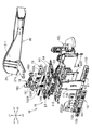
- FIG. 3 is an exploded perspective view showing the internal structure and the mounting band of the apparatus main body of the present embodiment.
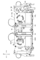
- FIG. 4 is a top view of the internal structure of the apparatus main body of the present embodiment as viewed from above.
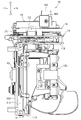
- FIG. 5 is a side view of the internal structure of the apparatus main body of the present embodiment as viewed from the left.
- FIG. 6 is a front view of the internal structure of the apparatus main body of the present embodiment as viewed from the front.
- the apparatus main body 10 includes a main frame 11, a right optical unit 12R, a left optical unit 12L, a camera unit 13, a circuit board 14, a cooling device 15, and a supported portion 16.
- a circuit board 14 is provided on the main frame 11, a cooling device 15 is provided on the circuit board 14, and a supported portion is provided on the cooling device 15. 16 is provided.
- the main frame 11 supports the right optical unit 12R, the left optical unit 12L, the camera unit 13, and the circuit board 14.
- the main frame 11 is preferably made of a lightweight and highly rigid material. For example, aluminum, magnesium, or the like may be used as the material of the main frame 11.
- the main frame 11 has a middle frame 111 extending in the vertical direction, an upper frame 112 connected to the upper part of the middle frame 111, and a lower frame 113 connected to the lower part of the middle frame 111.
- the middle frame 111 is provided substantially in the center of the apparatus main body 10.
- the width of the upper frame 112 and the lower frame 113 in the left-right direction is larger than the width of the middle frame 111 in the left-right direction. Therefore, as shown in FIG. 3 and the like, the main frame 11 has a shape in which the H shape is tilted 90 degrees laterally when viewed from the front-rear direction. That is, a space is formed between the right portion of the upper frame 112 and the right portion of the lower frame 113. Similarly, a space is formed between the left portion of the upper frame 112 and the left portion of the lower frame 113.
- the weight of the main frame 11 can be reduced as compared with the case where the shape (outer shape) when viewed from the front-rear direction is rectangular.
- the right optical unit 12R and the left optical unit 12L are arranged in a region formed between the middle frame 111 and the upper frame 112, and are supported by the middle frame 111, the upper frame 112, and the lower frame 113. ing.
- the right optical unit 12R has at least a lens (not shown) that guides the image light from the display device 110 to the user's right eye.
- the left optical unit 12L has at least a lens (not shown) that guides the image light from the display device 110 to the user's left eye.
- the display device 110 shown in FIG. 1 may be arranged in front of the lens included in the right optical unit 12R and the left optical unit 12L, respectively.
- the display device 110 may have a see-through type screen or may have a non-see-through type screen.
- the optical units 12R and 12L may have a nose pad or the like that comes into contact with the user's nose.
- the right optical unit 12R and the left optical unit 12L are supported by the main frame 11 so as to be movable left and right. Thereby, the user can adjust the distance between the lens included in the right optical unit 12R and the lens included in the left optical unit 12L in the left-right direction according to the distance between his / her left and right eyes. Further, as described above, in the main frame 11, a space is formed between the right portion of the upper frame 112 and the right portion of the lower frame 113, and the left portion of the upper frame 112 and the lower frame 113 A space is also formed between it and the left part.
- the configuration shown in the figure is an example, and the lens and the like are not limited to those that are unitized, and at least those that are built in the device main body 10 may be used.
- the camera unit 13 has at least a camera frame 131 and cameras 132 and 133 supported by the camera frame 131.
- the camera frame 131 is supported by the front portion of the middle frame 111.
- the cameras 132 and 133 are provided with an image sensor such as a CCD (Charge Coupled Device) or a CMOS (Complementary Metal Oxide Semiconductor), and image the front of the user wearing the HMD1.
- CCD Charge Coupled Device
- CMOS Complementary Metal Oxide Semiconductor
- a plurality of cameras 132 and 133 are provided, and for example, those used for SLAM (Simultaneous localization and mapping) that enable three-dimensional recognition by estimating the position and orientation of the camera from a captured image may be included. .. FIG. 2 and the like show a configuration in which four cameras are supported by the camera frame 131. However, the number and position of cameras are not limited to those shown in the figure. Although not shown, the housing 120 may have an opening so that the cameras 132 and 133 are exposed to each other.
- SLAM Simultaneous localization and mapping
- the circuit board 14 is supported by the upper frame 112.
- the size of the upper frame 112 may be larger than or substantially the same as the size of the circuit board 14. That is, the upper frame 112 may be a frame having a predetermined width in the front-rear direction and the left-right direction. As shown in FIG. 3 and the like, the upper frame 112 is connected to the upper part of the middle frame 111 so as to project rearward from the middle frame 111.
- the circuit board 14 mounts at least one or more electronic components.
- the surface of the circuit board 14 on which the integrated circuit 140 described later is mounted is referred to as a mounting surface 141.
- the circuit board 14 is supported by the upper frame 112 so that the mounting surface 141 faces upward when the HMD1 is in use.
- the apparatus main body 10 has a supported portion 16 on the upper portion thereof.
- the supported portion 16 is arranged above the cooling device 15.
- the supported portion 16 has a rail 161, an operation portion 162, and an operation assist portion 163.
- the rail 161 is provided so as to extend in the front-rear direction.
- the operation unit 162 is arranged on the right side of the rail 161 and projects upward.
- the operation assisting unit 163 is arranged on the left side of the rail 161 and projects upward.
- at least the rail 161 of the supported portion 16 is between the cooling fan 153R and the cooling fan 153L so as not to overlap the cooling fan 153R and the cooling fan 153L in the top view. It should be arranged.
- the support portion 212 of the front member 21 is fitted to the rail 161 so as to be slidable in the front-rear direction.
- the support portion 212 can move back and forth relative to the supported portion 16. That is, the device main body 10 can move back and forth relative to the mounting band 20. Therefore, the user can adjust the position of the apparatus main body 10 in the front-rear direction while the HMD1 is attached to the head H. As a result, the user can adjust the distance (also referred to as eye relief) between his / her own eye and the lens provided on the optical units 12R and 12L.
- the relative movement of the support portion 212 and the supported portion 16 is regulated by a regulation mechanism (not shown). Then, it is preferable that the user can switch from the state in which the relative movement between the support portion 212 and the supported portion 16 is restricted to the allowable state by operating the operation unit 162. For example, the user may push the operation unit 162 to the left (see the direction of the arrow in FIG. 6) to release the regulation by the regulation mechanism.
- the support portion 212 and the supported portion 16 can be relatively moved by the rack and pinion mechanism, and the regulation mechanism meshes with the rack gear or the pinion gear. , It is good that it is a mechanism that regulates their operation. Then, the operation unit 162 may release the engagement of the regulation mechanism with the rack gear or the pinion gear by operating the regulation mechanism. Further, the operation unit 162 may be configured to move to the original position (position shown in FIG. 3 or the like) by the elastic force of an elastic member such as a spring after receiving an operation from the user.
- the device main body 10 may have an operation assisting unit 163 so that the user can easily operate the operation unit 162.
- the user can easily push the operation unit 162 to the left by, for example, pinching the operation unit 162 and the operation assistance unit 163 with the index finger and the thumb.
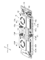
- FIG. 7 is a perspective view showing the cooling device and the circuit board of the present embodiment.
- FIG. 8 is a top view showing the cooling device and the circuit board of the present embodiment.
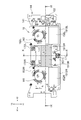
- FIG. 9 is a cross-sectional view showing a cross section cut along the IX-IX cutting line of FIG.
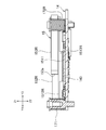
- FIG. 10 is a cross-sectional view showing a cross section cut along the XX cutting line of FIG.
- FIG. 11 is a front view schematically showing the vapor chamber and the electronic components mounted on the circuit board in this embodiment.
- FIG. 12 is an exploded perspective view showing the cooling device of the present embodiment.
- the cooling device 15 has a vapor chamber 151 which is a heat diffusion member, a right heat sink 152R, a left heat sink 152L, a right cooling fan 153R, and a left cooling fan 153L.
- the cooling device 15 is arranged so as to face the mounting surface 141 of the circuit board 14. More specifically, the vapor chamber 151 is arranged to face the mounting surface 141.
- the vapor chamber 151 includes a right mounting portion 1512R on which the right heat sink 152R and the right cooling fan 153R are mounted, and a left mounting portion 1512L on which the left heat sink 152L and the left cooling fan 153L are mounted. have.
- the vapor chamber 151 has a recessed portion (contact portion) 1511 provided between the right mounting portion 1512R and the left mounting portion 1512L.
- the vapor chamber 151 has a right connecting portion 1513R for connecting the right mounting portion 1512R and the recessed portion 1511, and a left connecting portion 1513L for connecting the left mounting portion 1512L and the recessed portion 1511.
- the right connecting portion 1513R is bent so as to be located upward from the recessed portion 1511 side toward the right mounting portion 1512R side. Therefore, the right mounting portion 1512R is located above the recessed portion 1511, and a gap is formed directly below the right connecting portion 1513R.
- the left connecting portion 1513L is bent so as to be located upward from the recessed portion 1511 side toward the left mounting portion 1512L side. Therefore, the left mounting portion 1512L is located above the recessed portion 1511, and a gap is formed directly below the left connecting portion 1513L.
- the vapor chamber 151 is filled with a fluid.
- the region of the vapor chamber 151 in which the fluid is sealed is defined as the heat diffusion region D.
- the region corresponding to the heat diffusion region D is shown by hatching.
- the heat diffusion region D is provided so as to straddle the right mounting portion 1512R, the right connecting portion 1513R, the recessed portion 1511, the left connecting portion 1513L, and the left mounting portion 1512L.
- the region directly below the heat sinks 152R and 152L is also a heat diffusion region D.
- the fluid sealed inside the vapor chamber 151 evaporates as the temperature rises, and heads toward the upper part inside the vapor chamber 151. As the fluid moves upward, heat is dissipated in the right heat sink 152R and the left heat sink 152L placed on the vapor chamber 151. The fluid is then condensed and the condensed fluid is circulated to the bottom of the vapor chamber 151.
- the right heat sink 152R and the left heat sink 152L are provided with a plurality of heat radiation fins extending upward from the circuit board 14 side. That is, the right heat sink 152R and the left heat sink 152L are configured to release the heat generated in the circuit board 14 upward.
- the recess portion 1511 is provided so that the lower surface thereof directly contacts the upper surface of the integrated circuit (IC) 140 mounted on the circuit board 14.
- the heat generated in the integrated circuit 140 is sent to the heat sinks 152R and 152L through the heat diffusion region D.
- the integrated circuit 140 may be, for example, a CPU (Central Processing Unit) that controls the entire HMD1.
- the present invention is not limited to this, and the integrated circuit 140 may be any circuit that consumes power as it is driven and can be a heat source.
- the integrated circuit 140 as the number and performance of the functions of the HMD1 are improved, the information processing becomes complicated and the power consumption increases. The larger the power consumption of the integrated circuit 140, the more heat is generated.
- the circuit board 14 mounts a plurality of electronic components.
- the thickness (height) of a plurality of electronic components varies.
- a gap sufficient for mounting electronic components is required between the cooling device 15 and the circuit board 14.
- the recessed portion 1511 of the vapor chamber 151 is in direct contact with the integrated circuit 140 as described above in order to enhance the heat dissipation effect. That is, the length between the lower surface of the recessed portion 1511 and the mounting surface 141 of the circuit board 14 substantially corresponds to the thickness of the integrated circuit 140.
- an electronic component E1 thicker than the integrated circuit 140 was arranged directly below the right mounting portion 1512R on the mounting surface 141.
- an electronic component E1 thicker than the integrated circuit 140 is arranged directly below the left mounting portion 1512L.
- the electronic component E1 may be arranged so that its upper surface is in contact with the lower surface of the right mounting portion 1512R or the left mounting portion 1512L. In this case, the heat generated from the electronic component E1 can be efficiently released.
- the electronic component E2 (second electronic component), which is thicker than the electronic component arranged directly under the right mounting portion 1512R and the left mounting portion 1512L, is as shown in FIGS. 7 and 11.
- the relatively thick connector may be arranged in a region of the mounting surface 141 that does not overlap with the cooling device 15 in the top view.
- the region of the mounting surface 141 that does not overlap with the cooling device 15 in the top view is the right portion or the left portion of the mounting surface 141.
- the electronic component E2 may be, for example, a connector to which various electrical wirings are connected.
- FIG. 11 for simplification, only one electronic component E1 is arranged directly under the right mounting portion 1512R and directly below the left mounting portion 1512L, but a plurality of electronic components E1 are arranged. It is good to have. Further, although only one electronic component E2 is shown in FIG. 11, it is preferable that a plurality of electronic components E2 are also arranged.
- the vapor chamber 151 is held in a state of being urged with respect to the circuit board 14 by the elastic force of the fixtures 171, 172R, and 172L having springs. Specifically, the fixtures 171 and 172R and 172L are inserted into the held holes 151h1, 151h2 and 151h3 shown in FIG. 12, respectively, and the holding holes 151h1 and 151h2 are provided by the springs included in the fixtures 171, 172R and 172L. , 151h3 may be pressed downward. With such a configuration, the recessed portion 1511 of the vapor chamber 151 elastically contacts the integrated circuit 140 mounted on the circuit board 14. Therefore, the contact state between the recessed portion 1511 and the integrated circuit 140 is stable, and the heat generated in the integrated circuit 140 can be more effectively transferred to the vapor chamber 151.
- the fixtures 171 and 172R and 172L are held between the circuit board 14 and the supported portion 16. That is, as shown in FIG. 6, the fixtures 171 and 172R and 172L may have a function of supporting the supported portion 161. Further, as shown in FIG. 6, the fixtures 171, 172R, and 172L may be arranged between the cooling fan 153R and the cooling fan 153L in the left-right direction. As a result, the circuit board 14 and the cooling device 15 can be arranged on the upper part of the apparatus main body 10, and the supported portion 161 can be arranged on the upper part and the center of the apparatus main body 10.
- the heat from the integrated circuit 140 can be efficiently released, and a plurality of electronic components can be mounted on the circuit board 14 without increasing the mounting surface 141 of the circuit board 14. It is possible to implement it in.
- the right heat sink 152R and the right cooling fan 153R are mounted on the right mounting portion 1512R of the vapor chamber 151.
- the right heat sink 152R and the right cooling fan 153R are provided adjacent to each other in the front-rear direction.
- the left heat sink 152L and the left cooling fan 153L are mounted on the left mounting portion 1512L of the vapor chamber 151.
- the left heat sink 152L and the left cooling fan 153L are provided adjacent to each other in the front-rear direction.
- the right cooling fan 153R has a blade W1 that rotates about a central axis OR (see FIGS. 8 and 9) extending in a direction extending through the circuit board 14.
- the left cooling fan 153L has blades W2 that rotate about a central axis OL (see FIGS. 8 and 9) extending in a direction penetrating the circuit board 14.
- the housing of the right cooling fan 153R is formed with an air outlet 153a that opens facing the right heat sink 152R.
- the housing of the left cooling fan 153L is also formed with an air outlet 153b that opens facing the left heat sink 152L.
- the blade W1 of the right cooling fan 153R is rotationally driven to generate cooling air sent toward the heat sink 152R through the air outlet 153a.
- cooling air sent toward the heat sink 152L through the air outlet 153b is generated.
- the direction of the cooling air generated by the cooling fans 153R and 153L is not limited to that described here.
- the cooling fans 153R and 153L may blow cooling air toward the circuit board 14.
- the air trapped below the cooling fans 153R and 152L may be sucked in and sent upward.
- the configuration shown in the present embodiment is effective for HMD1 which consumes a large amount of power in electronic components by improving the number of functions and performance. Specifically, for example, it is effective for HMD1 that employs a wireless communication technology that consumes a large amount of power.
- the circuit board 14 and the cooling device 15 having a certain weight are arranged at the front portion of the device main body 10 which is a position far from the head H of the user who wears the HMD 1, the center of gravity of the device main body 10 Will be located in front.
- the camera is further forward than them.
- the unit 13 will be arranged.
- the load applied to the user wearing the HMD1 increases, and the HMD1 tends to slip off from the user's head H. Therefore, it is necessary to take measures such as firmly fixing the wearing band 20 to the user's head H so that the HMD 1 does not slip off.
- the HMD1 of the present embodiment since the circuit board 14 and the cooling device 15 are arranged in the upper part of the apparatus main body 10, the HMD1 is compared with the configuration in which they are arranged in the front part of the apparatus main body 10. The load applied to the wearing user can be suppressed, and the HMD1 can be prevented from easily slipping off from the user's head H.
- the configuration of the HMD 1 described in the above embodiment is an example, and at least the circuit board 14 and the cooling device 15 may be arranged on the upper part of the apparatus main body 10.
- the configurations of the optical units 12R and 12L and the main frame 11 are not limited to those shown in the drawings.
- the cooling device 15 has the vapor chamber 151, the heat sinks 152R and 152L, and the cooling fans 153R and 153L has been described, but the present invention is not limited to this, and it occurs at least in the circuit board 14. Anything that has a cooling effect on the heat generated may be used. That is, the cooling device 15 may have only one of the vapor chamber, the heat sink, and the cooling fan, or may have other cooling structures. As another cooling structure, for example, a structure having a heat pipe may be used.
- cooling device 15 has two heat sinks and two cooling fans
- the present invention is not limited to this.
- support portions 212 may be formed on the right portion and the left portion, respectively, and one heat sink and one cooling fan may be provided between the two support portions 212.
- the mounting band 20 includes the front member 21 and is connected to the device main body 10 via the front member 21, but the present invention is not limited to this.
- the band portion of the mounting band 20 extending rearward may be directly connected to the device main body 10.
- HMD head-mounted display
Landscapes
- Physics & Mathematics (AREA)
- Engineering & Computer Science (AREA)
- General Physics & Mathematics (AREA)
- Theoretical Computer Science (AREA)
- Optics & Photonics (AREA)
- Computer Hardware Design (AREA)
- Human Computer Interaction (AREA)
- General Engineering & Computer Science (AREA)
- Devices For Indicating Variable Information By Combining Individual Elements (AREA)
- Cooling Or The Like Of Electrical Apparatus (AREA)
Priority Applications (4)
| Application Number | Priority Date | Filing Date | Title |
|---|---|---|---|
| PCT/JP2019/011518 WO2020188760A1 (ja) | 2019-03-19 | 2019-03-19 | ヘッドマウントディスプレイ |
| US17/435,872 US12117618B2 (en) | 2019-03-19 | 2019-03-19 | Head-mounted display |
| JP2021506903A JP7279151B2 (ja) | 2019-03-19 | 2019-03-19 | ヘッドマウントディスプレイ |
| JP2023078015A JP7490112B2 (ja) | 2019-03-19 | 2023-05-10 | ヘッドマウントディスプレイ |
Applications Claiming Priority (1)
| Application Number | Priority Date | Filing Date | Title |
|---|---|---|---|
| PCT/JP2019/011518 WO2020188760A1 (ja) | 2019-03-19 | 2019-03-19 | ヘッドマウントディスプレイ |
Publications (1)
| Publication Number | Publication Date |
|---|---|
| WO2020188760A1 true WO2020188760A1 (ja) | 2020-09-24 |
Family
ID=72519756
Family Applications (1)
| Application Number | Title | Priority Date | Filing Date |
|---|---|---|---|
| PCT/JP2019/011518 Ceased WO2020188760A1 (ja) | 2019-03-19 | 2019-03-19 | ヘッドマウントディスプレイ |
Country Status (3)
| Country | Link |
|---|---|
| US (1) | US12117618B2 (https=) |
| JP (2) | JP7279151B2 (https=) |
| WO (1) | WO2020188760A1 (https=) |
Cited By (1)
| Publication number | Priority date | Publication date | Assignee | Title |
|---|---|---|---|---|
| JP2023049402A (ja) * | 2021-09-29 | 2023-04-10 | キヤノン株式会社 | 画像表示装置。 |
Families Citing this family (12)
| Publication number | Priority date | Publication date | Assignee | Title |
|---|---|---|---|---|
| KR102751012B1 (ko) * | 2020-01-06 | 2025-01-06 | 엘지전자 주식회사 | 디스플레이 디바이스 |
| US11669127B2 (en) * | 2021-06-30 | 2023-06-06 | Meta Platforms Technologies, Llc | Extended reality headset positioning and stabilization |
| US11782281B2 (en) * | 2021-07-30 | 2023-10-10 | Meta Platforms Technologies, Llc | Thermal management system for electronic device |
| US12222515B2 (en) * | 2022-06-29 | 2025-02-11 | Meta Platforms Technologies, Llc | Apparatus, systems, and methods for heat transfer in optical devices |
| US20240012256A1 (en) * | 2022-07-07 | 2024-01-11 | Apple Inc. | Head-Mounted Display |
| EP4554348A4 (en) * | 2022-08-29 | 2025-11-05 | Samsung Electronics Co Ltd | ELECTRONIC DEVICE COMPRISING A HEAT PIPE SURROUNDING MULTIPLE INTEGRATED CIRCUITS |
| CN116381931A (zh) * | 2023-01-17 | 2023-07-04 | 富泰华工业(深圳)有限公司 | 头戴式设备 |
| WO2024232497A2 (ko) * | 2023-05-09 | 2024-11-14 | 삼성전자 주식회사 | 방열 구조를 포함하는 웨어러블 전자 장치 |
| EP4651653A4 (en) | 2023-05-09 | 2026-04-29 | Samsung Electronics Co Ltd | Wearable electronic device incorporating a heat dissipation structure |
| CN121100303A (zh) * | 2023-05-12 | 2025-12-09 | 三星电子株式会社 | 散热构件和包括散热构件的可穿戴电子装置 |
| CN120215113A (zh) * | 2023-12-26 | 2025-06-27 | 北京字跳网络技术有限公司 | 头戴显示设备 |
| WO2026058974A1 (ko) * | 2024-09-10 | 2026-03-19 | 엘지전자 주식회사 | 디스플레이 디바이스 및 이를 구비하는 전자 디바이스 |
Citations (6)
| Publication number | Priority date | Publication date | Assignee | Title |
|---|---|---|---|---|
| JPH0915527A (ja) * | 1995-06-27 | 1997-01-17 | Olympus Optical Co Ltd | 頭部装着型映像表示装置 |
| JPH11202795A (ja) * | 1998-01-09 | 1999-07-30 | Canon Inc | 映像表示装置 |
| JP2007012912A (ja) * | 2005-06-30 | 2007-01-18 | Polymatech Co Ltd | 熱伝導性部材および該熱伝導性部材を用いた冷却構造 |
| WO2015008326A1 (ja) * | 2013-07-16 | 2015-01-22 | 三協立山株式会社 | ヒートシンク及びヒートシンクの製造方法 |
| WO2015137165A1 (ja) * | 2014-03-14 | 2015-09-17 | 株式会社ソニー・コンピュータエンタテインメント | ヘッドマウントディスプレイ |
| US20170184863A1 (en) * | 2015-12-24 | 2017-06-29 | Sulon Technologies Inc. | Cooling system for head mounted device |
Family Cites Families (18)
| Publication number | Priority date | Publication date | Assignee | Title |
|---|---|---|---|---|
| JP2959000B2 (ja) | 1989-12-19 | 1999-10-06 | ソニー株式会社 | 顔面装着型視覚装置 |
| JPH0713100A (ja) | 1993-06-25 | 1995-01-17 | Olympus Optical Co Ltd | 頭部装着式ディスプレイ |
| JPH0934376A (ja) * | 1995-07-21 | 1997-02-07 | Olympus Optical Co Ltd | 頭部装着型映像表示装置 |
| JP2005296467A (ja) | 2004-04-14 | 2005-10-27 | Olympus Corp | 立体内視鏡用表示制御装置 |
| JP4528289B2 (ja) | 2006-07-31 | 2010-08-18 | オリンパス株式会社 | 頭部装着型映像表示装置 |
| JP2018101704A (ja) | 2016-12-20 | 2018-06-28 | キヤノン株式会社 | 電子機器 |
| CN106873165A (zh) | 2017-04-10 | 2017-06-20 | 北京小米移动软件有限公司 | 虚拟现实眼镜 |
| WO2018188079A1 (zh) | 2017-04-14 | 2018-10-18 | 深圳市大疆创新科技有限公司 | 头戴设备及具有该头戴设备的视频眼镜 |
| US10379583B2 (en) * | 2017-04-19 | 2019-08-13 | Facebook Technologies, Llc | System for discharging heat out of head-mounted display based on hybrid fan and heat pipe |
| JP2018190825A (ja) | 2017-05-02 | 2018-11-29 | キヤノン株式会社 | 電気機器 |
| CN206975323U (zh) | 2017-06-30 | 2018-02-06 | 深圳市大疆创新科技有限公司 | 头戴式显示设备 |
| US10579114B1 (en) * | 2017-08-15 | 2020-03-03 | Facebook Technologies, Llc | Heat dissipating assembly for head-mounted displays |
| CN107454805B (zh) | 2017-08-28 | 2023-10-27 | 歌尔科技有限公司 | Vr产品散热结构 |
| US10620439B1 (en) * | 2017-10-17 | 2020-04-14 | Facebook Technologies, Llc | Processor thermal management for liquid crystal temperature regulation |
| CN111007666A (zh) * | 2018-10-08 | 2020-04-14 | 宏达国际电子股份有限公司 | 头戴式显示装置 |
| US11058026B1 (en) * | 2019-04-19 | 2021-07-06 | Apple Inc. | Air deflector for cooling system in a head-mounted device |
| CN213042193U (zh) | 2020-10-30 | 2021-04-23 | 歌尔光学科技有限公司 | 一种头戴显示设备、风冷散热器及侧置散热结构 |
| CN112099238B (zh) | 2020-10-30 | 2022-07-08 | 歌尔光学科技有限公司 | 一种头戴显示设备及其前端风冷散热结构 |
-
2019
- 2019-03-19 JP JP2021506903A patent/JP7279151B2/ja active Active
- 2019-03-19 WO PCT/JP2019/011518 patent/WO2020188760A1/ja not_active Ceased
- 2019-03-19 US US17/435,872 patent/US12117618B2/en active Active
-
2023
- 2023-05-10 JP JP2023078015A patent/JP7490112B2/ja active Active
Patent Citations (6)
| Publication number | Priority date | Publication date | Assignee | Title |
|---|---|---|---|---|
| JPH0915527A (ja) * | 1995-06-27 | 1997-01-17 | Olympus Optical Co Ltd | 頭部装着型映像表示装置 |
| JPH11202795A (ja) * | 1998-01-09 | 1999-07-30 | Canon Inc | 映像表示装置 |
| JP2007012912A (ja) * | 2005-06-30 | 2007-01-18 | Polymatech Co Ltd | 熱伝導性部材および該熱伝導性部材を用いた冷却構造 |
| WO2015008326A1 (ja) * | 2013-07-16 | 2015-01-22 | 三協立山株式会社 | ヒートシンク及びヒートシンクの製造方法 |
| WO2015137165A1 (ja) * | 2014-03-14 | 2015-09-17 | 株式会社ソニー・コンピュータエンタテインメント | ヘッドマウントディスプレイ |
| US20170184863A1 (en) * | 2015-12-24 | 2017-06-29 | Sulon Technologies Inc. | Cooling system for head mounted device |
Cited By (2)
| Publication number | Priority date | Publication date | Assignee | Title |
|---|---|---|---|---|
| JP2023049402A (ja) * | 2021-09-29 | 2023-04-10 | キヤノン株式会社 | 画像表示装置。 |
| JP7760312B2 (ja) | 2021-09-29 | 2025-10-27 | キヤノン株式会社 | 画像表示装置 |
Also Published As
| Publication number | Publication date |
|---|---|
| JP7490112B2 (ja) | 2024-05-24 |
| JPWO2020188760A1 (https=) | 2020-09-24 |
| US12117618B2 (en) | 2024-10-15 |
| JP2023103349A (ja) | 2023-07-26 |
| US20220146838A1 (en) | 2022-05-12 |
| JP7279151B2 (ja) | 2023-05-22 |
Similar Documents
| Publication | Publication Date | Title |
|---|---|---|
| JP7490112B2 (ja) | ヘッドマウントディスプレイ | |
| EP3392690B1 (en) | System for discharging heat out of head-mounted display based on hybrid fan and heat pipe | |
| JP6662474B2 (ja) | 頭部装着型装置 | |
| CN110873965B (zh) | 图像投射光学组件和头戴式显示器 | |
| JP7272040B2 (ja) | 装着型表示装置 | |
| JPWO2020188760A5 (https=) | ||
| US11397328B2 (en) | Wearable display device | |
| US11490547B2 (en) | Wearable display device | |
| JP2023021774A (ja) | 撮像装置 | |
| JP6451302B2 (ja) | 画像表示装置及び頭部装着型画像表示装置 | |
| CN110996608B (zh) | 电子设备 | |
| KR20220070977A (ko) | 방열 부재를 포함하는 전자 장치 | |
| JP6753046B2 (ja) | 画像表示装置及び頭部装着型画像表示装置 | |
| JP6446257B2 (ja) | ヘッドマウントディスプレイ | |
| CN113811815B (zh) | 热传导机构 | |
| JP2018007050A (ja) | ヘッドマウントディスプレイ | |
| EP4651653A2 (en) | Wearable electronic device comprising heat dissipation structure | |
| JP7760312B2 (ja) | 画像表示装置 | |
| US12393034B2 (en) | Wearable projection device | |
| JP2012156618A (ja) | 頭部装着撮像装置 | |
| JP2009156912A (ja) | 携帯電子機器 | |
| JP2016201754A (ja) | 画像情報処理装置 | |
| US20250251610A1 (en) | Wearable display device | |
| JP2015073163A (ja) | 撮像装置 | |
| US20240061257A1 (en) | Image display device |
Legal Events
| Date | Code | Title | Description |
|---|---|---|---|
| 121 | Ep: the epo has been informed by wipo that ep was designated in this application |
Ref document number: 19920058 Country of ref document: EP Kind code of ref document: A1 |
|
| ENP | Entry into the national phase |
Ref document number: 2021506903 Country of ref document: JP Kind code of ref document: A |
|
| NENP | Non-entry into the national phase |
Ref country code: DE |
|
| 122 | Ep: pct application non-entry in european phase |
Ref document number: 19920058 Country of ref document: EP Kind code of ref document: A1 |