WO2020184239A1 - 通信装置、通信システム及びメッセージ調停方法 - Google Patents
通信装置、通信システム及びメッセージ調停方法 Download PDFInfo
- Publication number
- WO2020184239A1 WO2020184239A1 PCT/JP2020/008587 JP2020008587W WO2020184239A1 WO 2020184239 A1 WO2020184239 A1 WO 2020184239A1 JP 2020008587 W JP2020008587 W JP 2020008587W WO 2020184239 A1 WO2020184239 A1 WO 2020184239A1
- Authority
- WO
- WIPO (PCT)
- Prior art keywords
- message
- time
- transmission
- communication
- arbitration
- Prior art date
- Legal status (The legal status is an assumption and is not a legal conclusion. Google has not performed a legal analysis and makes no representation as to the accuracy of the status listed.)
- Ceased
Links
Images




Classifications
-
- H—ELECTRICITY
- H04—ELECTRIC COMMUNICATION TECHNIQUE
- H04L—TRANSMISSION OF DIGITAL INFORMATION, e.g. TELEGRAPHIC COMMUNICATION
- H04L12/00—Data switching networks
- H04L12/28—Data switching networks characterised by path configuration, e.g. LAN [Local Area Networks] or WAN [Wide Area Networks]
- H04L12/40—Bus networks
- H04L12/403—Bus networks with centralised control, e.g. polling
-
- H—ELECTRICITY
- H04—ELECTRIC COMMUNICATION TECHNIQUE
- H04L—TRANSMISSION OF DIGITAL INFORMATION, e.g. TELEGRAPHIC COMMUNICATION
- H04L12/00—Data switching networks
- H04L12/28—Data switching networks characterised by path configuration, e.g. LAN [Local Area Networks] or WAN [Wide Area Networks]
- H04L12/46—Interconnection of networks
- H04L12/4604—LAN interconnection over a backbone network, e.g. Internet, Frame Relay
- H04L12/462—LAN interconnection over a bridge based backbone
- H04L12/4625—Single bridge functionality, e.g. connection of two networks over a single bridge
-
- H—ELECTRICITY
- H04—ELECTRIC COMMUNICATION TECHNIQUE
- H04L—TRANSMISSION OF DIGITAL INFORMATION, e.g. TELEGRAPHIC COMMUNICATION
- H04L12/00—Data switching networks
- H04L12/28—Data switching networks characterised by path configuration, e.g. LAN [Local Area Networks] or WAN [Wide Area Networks]
- H04L12/40—Bus networks
- H04L12/40006—Architecture of a communication node
- H04L12/40026—Details regarding a bus guardian
-
- H—ELECTRICITY
- H04—ELECTRIC COMMUNICATION TECHNIQUE
- H04L—TRANSMISSION OF DIGITAL INFORMATION, e.g. TELEGRAPHIC COMMUNICATION
- H04L12/00—Data switching networks
- H04L12/28—Data switching networks characterised by path configuration, e.g. LAN [Local Area Networks] or WAN [Wide Area Networks]
- H04L12/40—Bus networks
- H04L2012/40208—Bus networks characterized by the use of a particular bus standard
- H04L2012/40215—Controller Area Network CAN
-
- H—ELECTRICITY
- H04—ELECTRIC COMMUNICATION TECHNIQUE
- H04L—TRANSMISSION OF DIGITAL INFORMATION, e.g. TELEGRAPHIC COMMUNICATION
- H04L12/00—Data switching networks
- H04L12/28—Data switching networks characterised by path configuration, e.g. LAN [Local Area Networks] or WAN [Wide Area Networks]
- H04L12/40—Bus networks
- H04L2012/40267—Bus for use in transportation systems
- H04L2012/40273—Bus for use in transportation systems the transportation system being a vehicle
Definitions
- the present disclosure relates to a communication device, a communication system, and a message arbitration method for transmitting and receiving messages via a common communication line.
- a vehicle is equipped with a plurality of devices such as an ECU (Electronic Control Unit). These plurality of devices are connected to each other via a communication line, exchange information by transmitting and receiving messages, and realize various functions of the vehicle in cooperation.
- ECU Electronic Control Unit
- the communication standard of CAN Controller Area Network
- CAN Controller Area Network
- Patent Document 1 proposes an in-vehicle network expansion device that can be expected to efficiently arbitrate communication between communication lines when the CAN communication lines arranged in the vehicle are divided into multiple systems.
- This in-vehicle network expansion device includes a circuit that arbitrates communication between communication lines based on the priority given to a message when a communication collision occurs between communication lines.
- arbitration processing arbitration processing
- the transmission of any one message is permitted, and the transmission of the other messages is stopped.
- Which message transmission is prioritized is determined based on the ID attached to the message. The smaller the value of the CAN ID, the higher the priority.
- the CAN ID is statically determined, for example, at the design stage of a communication device or a communication system. In the conventional CAN arbitration process, the transmission of a low priority message may continue to be hindered by the transmission of a high priority message.
- the present disclosure has been made in view of such circumstances, and an object of the present invention is to provide a communication device, a communication system, and a message arbitration method capable of suppressing the transmission of a message from being hindered for a long period of time. To provide.
- the communication device is a communication device that transmits / receives a message to / from another device connected to a shared communication line, and for a message to be transmitted, until the time when the transmission of the message should be completed.
- a calculation unit that calculates the margin time, a transmission unit that transmits information according to the margin time calculated by the calculation unit to the message, and a message to the communication line based on the information attached to the message.
- the arbitration unit includes an arbitration unit that arbitrates when transmissions are duplicated, and the arbitration unit performs arbitration for a plurality of messages that are duplicated and transmitted to the communication line, giving priority to a message having a short margin time.
- the present application can be realized not only as a communication device provided with such a characteristic processing unit, but also as a message arbitration method in which the characteristic processing is a step, or for causing a computer to execute such a step. It can be realized as a computer program. It can be realized as a semiconductor integrated circuit that realizes a part or all of the communication device, or can be realized as another device or system including the communication device.
- the communication device is a communication device that transmits / receives a message to / from another device connected to a shared communication line, and should complete the transmission of the message to be transmitted.
- the communication unit based on the calculation unit that calculates the margin time until the time, the transmission unit that attaches the information corresponding to the margin time calculated by the calculation unit to the message, and transmits the information attached to the message.
- the arbitration unit is provided with an arbitration unit that performs arbitration when message transmissions to the lines are duplicated, and the arbitration unit gives priority to arbitration for a plurality of messages transmitted to the communication lines in an overlapping manner with a short margin time. Do.
- the margin time until the time when the transmission of this message should be completed is calculated.
- the communication device attaches the information according to the margin time calculated at the time of attempting to transmit the message to this message as arbitration information and attempts to transmit the message. If the transmission of its own message and the transmission of a message from another communication device connected to a common communication line occur at the same time and a message transmission conflict occurs, the communication device gives priority to the transmission of any message. Perform arbitration processing to determine whether to perform. At this time, the communication device performs arbitration processing so as to give priority to the transmission of the message having the short spare time based on the information of the spare time attached to each message. As a result, the arbitration process in which the priority is changed according to the margin time of the message becomes possible, and it is possible to suppress the transmission of a specific message from being continuously hindered for a long period of time.
- the transmission unit transmits the information according to the margin time calculated by the calculation unit and the identification information for identifying the message or the identification information for identifying the device attached to the message.
- the communication device attaches the information according to the spare time of the message and the identification information of the message or the identification information of the device to the message as arbitration information and transmits the information.
- the communication device can perform arbitration processing based on the identification information.
- a processor, a communication controller having the calculation unit, the transmission unit, and the arbitration unit, and transmitting and receiving a message to the communication line according to the processing of the processor, and the communication controller is a message. It has a storage unit for storing information related to the time when transmission should be completed, and the calculation unit has the margin based on the time when a message transmission request is given from the processor and the information stored in the storage unit. It is preferable to calculate the time.
- the communication device includes a processor and a communication controller.
- the communication controller sends and receives messages according to the processing of the processor, and also performs processing such as calculation of the above-mentioned margin time and arbitration of messages.
- the communication controller stores information about when the message should be sent.
- the communication controller calculates the margin time of the message based on the information about the time when the message transmission request is given from the processor and the time stored in the storage unit. As a result, the processor and the application program or the like executed on the processor do not need to perform processing such as calculation of the margin time of the message and arbitration.
- the message is a message that conforms to the communication standard of CAN (Controller Area Network), and it is preferable that the transmitting unit stores information according to the spare time in the arbitration field of the CAN message and transmits it. ..
- the communication device sends and receives messages according to the CAN communication standard.
- the communication device stores the calculated information according to the margin time in the arbitration field of the CAN message and transmits the information.
- message arbitration is performed assuming that the smaller the value stored in the arbitration field, the higher the priority.
- a relay unit that is connected to a plurality of communication lines and performs a process of transmitting a message received on one communication line from another communication line, and the message attached to the message received on the one communication line. It is preferable that the calculation unit includes an acquisition unit that acquires information according to the margin time, and the calculation unit calculates the margin time of the relayed message based on the information acquired by the acquisition unit.
- the communication device may be connected to a plurality of communication lines, and may relay a message received on one communication line and transmitted from another communication line.
- the communication device acquires information according to the spare time attached to the message received on one communication line.
- the communication device calculates the margin time of the relaying message based on the acquired information.
- the communication device can calculate the spare time of the relayed message by using the spare time based on the acquired information as the time to complete the transmission of this message.
- the transmission unit receives either the information related to the margin time calculated by the calculation unit or the identification information statically determined for the message. It is preferable to selectively send the message.
- the communication device can selectively transmit a message with information related to the above-mentioned spare time and a message with statically determined identification information. Mediation by each communication device is possible by treating both the information related to the spare time and the statically determined identification information as the same numerical information without distinguishing between them. The communication device can appropriately select whether to send the message with the information related to the spare time or the identification information.
- the communication system is a communication system in which a plurality of communication devices connected to a shared communication line transmit and receive a message, and the communication device transmits the message with respect to the message to be transmitted. Based on the calculation unit that calculates the margin time until the time to be completed, the transmission unit that attaches the information according to the margin time calculated by the calculation unit to the message, and transmits the information, and the information attached to the message.
- the mediation unit is provided with an arbitration unit that mediates when message transmissions to the communication line are duplicated, and the arbitration unit gives priority to a message having a short margin time for a plurality of messages transmitted to the communication line in an overlapping manner. Mediate.
- the arbitration process in which the priority is changed according to the margin time of the message becomes possible, and the transmission of a specific message is continuously hindered for a long period of time. Can be suppressed.
- the transmission unit When the transmission unit cannot transmit the message, the transmission unit retransmits the message after the elapse of a predetermined waiting time, and the waiting time is set to a different time for each communication device. preferable.
- the communication device when the transmission of a message by a plurality of communication devices is duplicated and the message cannot be transmitted due to the arbitration process, the communication device attempts to retransmit this message after the elapse of a predetermined waiting time. For a plurality of communication devices connected to a common communication line, the waiting time until message retransmission is set to a different time for each communication device. As a result, even when a plurality of messages having the same margin time are simultaneously transmitted and cannot be transmitted together, a difference can be provided in the timing of transmitting the next message.
- the plurality of communication devices include a communication device that attaches information according to the margin time to a message as information used for mediation of the mediation unit, and the mediation that statically defines identification information for the message. It is preferable to include a communication device attached to the message as information used for arbitration of the unit.
- a communication device that transmits a message with information according to a margin time and a communication device that transmits a message with statically determined identification information are mixed in the communication system. It is possible.
- the message arbitration method is a message arbitration method for arbitrating when message transmissions by a plurality of communication devices connected to a common communication line are duplicated, and each communication device should transmit.
- the margin time until the time when the transmission of the message should be completed is calculated, the information corresponding to the calculated margin time is attached to the message and transmitted, and the communication is performed based on the information attached to the message. For multiple messages sent in duplicate for a line, arbitration is performed to give priority to messages with less spare time.
- the arbitration process in which the priority is changed according to the margin time of the message becomes possible, and the transmission of a specific message is continuously hindered for a long period of time. Can be suppressed.
- FIG. 1 is a schematic diagram for explaining an outline of the communication system according to the present embodiment.
- the communication system according to the present embodiment is a system in which a plurality of ECUs 2 mounted on the vehicle 1 send and receive messages in accordance with CAN communication standards.
- the plurality of ECUs 2 are each connected to the CAN bus 3 arranged in the vehicle 1.
- Several to a dozen or more ECUs 2 may be connected to one CAN bus 3.
- the vehicle 1 may be provided with a plurality of CAN buses 3.
- the gateway 4 is mounted on the vehicle 1.
- a plurality of CAN buses 3 are connected to the gateway 4, and the transmission / reception of a message between the plurality of CAN buses 3 is relayed.
- the vehicle 1 is provided with two CAN buses 3.
- the two CAN buses 3 are connected to the gateway 4.
- Four ECUs 2 are connected to each CAN bus 3.
- the eight ECUs 2 can send and receive messages to and from each other via two CAN buses 3 and one gateway 4.
- the number of ECUs 2 included in the communication system, the number of CAN buses 3, the number of gateways 4, the connection mode of the devices, the network configuration, and the like are not limited to those shown in the drawings.
- the ECU 2 includes, for example, an ECU that controls the operation of the engine of the vehicle 1, an ECU that controls the lock / unlock of the door, an ECU that controls the on / off of the light, an ECU that controls the operation of the airbag, and ABS (ABS).
- Various ECUs such as an ECU that controls the operation of the Antilock Brake System) may be included.
- the ECU 2 and the gateway 4 are mentioned as communication devices that perform communication via the CAN bus 3, but the communication devices are not limited thereto.
- CANID For messages that comply with CAN communication standards, identification information called CANID is stored in the beginning area of the message called arbitration field.
- the CANID is information indicating the type of data included in this message and the priority of this message. The smaller the value of CANID, the higher the priority of the message.
- arbitration arbitration
- CANID is a static value determined by the designer at the design stage of the vehicle 1, the communication system, the ECU 2, or the like.
- each ECU 2 dynamically changes the value stored in the arbitration field of the message, thereby dynamically changing the priority of the message. Specifically, the ECU 2 according to the present embodiment calculates a margin time for the time when the message transmission should be completed, stores the information related to the calculated margin time in the arbitration field of the message, and transmits the message. The margin time indicates that the smaller the value, the smaller the margin.
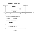
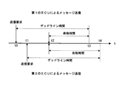
- FIG. 2 is a schematic diagram for explaining the margin time of the message, and shows a timing chart of message transmission with the horizontal axis as the time t.
- the ECU 2 according to the present embodiment repeatedly transmits a message, for example, in a predetermined transmission cycle T.
- the transmission request time of the first message of the ECU 2 is t0
- the transmission request time of the second message is t1.
- the transmission cycle T t1-t0.
- the time for completing the transmission of the message from the transmission request time is preset as the deadline time TD.
- the time when the deadline time TD elapses with respect to the transmission request time t0 is defined as the deadline time td.
- the ECU 2 may be made to wait for its own message transmission. This is, for example, when the message transmission by the other ECU 2 has already been performed, or when the other ECU 2 attempts to transmit the message at the same time and the right to transmit the message itself is not obtained by the arbitration process. .. In such a case, the ECU 2 attempts to retransmit the message after a predetermined waiting time. In the illustrated example, the ECU 2 has acquired the right to transmit a message and has started transmission at the time of the transmission start time ts when the waiting time has elapsed.
- the message transmission time depends on the data size of the message, and in the illustrated example, the ECU 2 ends the message transmission at the time of the transmission end time te.
- the period from the transmission request time t0 to the message transmission end time te corresponds to the delay time of this message.
- the deadline time TD is set in advance for each message transmitted by the ECU 2.
- the deadline time TD is a set value that defines the time for completing the transmission of this message from the message transmission request time t0. Assuming that the time when the deadline time TD is added to the transmission request time t0 is the deadline time dt, the message transmission end time te must be earlier than the deadline time td. However, the operation may be based on the rule that the message transmission start time ts may be earlier than the deadline time td.
- the deadline time TD is set to a time equal to or less than the transmission cycle T of this message.
- the time from the message transmission start time to the deadline time dt is set as the margin time.
- the ECU 2 calculates the margin time of the message to be transmitted.
- the ECU 2 acquires the transmission right of the message at the transmission start time ts, the ECU 2 stores the calculated margin time in the arbitration field of this message and transmits the message.
- the margin time calculated by the ECU 2 and the margin time stored in the message may be a numerical value of the real time, but in the present embodiment, it is represented by the number of clocks of the clock signal used for the communication processing. For example, when the clock period is 2 ⁇ sec and the real time is 500 ⁇ sec, the number of clocks is 250. Information about the clock period is shared among the plurality of ECUs 2.
- the information regarding the margin time stored in the message can be the number of clocks corresponding to the time from the transmission start time ts of the message shown in FIG. 2 to the deadline time td.
- the number of clocks corresponding to the time from the message transmission end time te to the deadline time td may be stored in the message.
- Each ECU 2 stores the margin time in the arbitration field of the message in the same manner and transmits the message.
- the shorter the margin time until the deadline time td the smaller the value of the margin time stored in the message.
- the smaller the value stored in the arbitration field of a message the higher the priority of the message. That is, in the communication system according to the present embodiment, the message having a short margin time is preferentially transmitted.
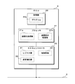
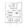
- FIG. 3 is a block diagram showing a configuration of the ECU 2 according to the present embodiment.
- the ECU 2 according to the present embodiment includes a processor 21, a storage unit (storage) 22, a CAN controller 23, and the like.
- the processor 21 reads and executes the program 22a stored in the storage unit 22 to perform various processes such as control processing of the vehicle 1.
- the processor 21 when the processor 21 needs to transmit a message to another ECU 2 in control processing or the like, the processor 21 gives a message to be transmitted to the CAN controller 23 and instructs the CAN controller 23 to transmit this message.
- the storage unit 22 is configured by using a non-volatile memory element such as a flash memory or an EEPROM (Electrically Erasable Programmable Read Only Memory).
- the storage unit 22 stores various programs executed by the processor 21 and various data required for processing by the processor 21.
- the storage unit 22 stores the program 22a executed by the processor 21.
- the program 22a may be written in the storage unit 22 at the manufacturing stage of the ECU 2, for example.
- the ECU 2 may acquire what is distributed by a remote server device or the like by communication.
- the ECU 2 may read the program 22a recorded on a recording medium such as a memory card or an optical disk and store it in the storage unit 22.
- the writing device may read out what is recorded on the recording medium and write it in the storage unit 22 of the ECU 2.
- the program 22a may be provided in a mode of distribution via a network, or may be provided in a mode recorded on a recording medium.
- the CAN controller 23 sends and receives messages via the CAN bus 3.
- the CAN controller 23 can be configured as, for example, one IC (Integrated Circuit).
- the CAN controller 23 is connected to another ECU 2 and a gateway 4 or the like via a CAN bus 3 arranged in the vehicle 1, and communicates with these other in-vehicle devices in accordance with the CAN communication standard.
- the CAN controller 23 converts a transmission message given by the processor 21 into an electric signal according to the CAN communication standard and outputs the message to the CAN bus 3 to transmit the message to another in-vehicle device.
- the CAN controller 23 receives a message from another vehicle-mounted device by sampling and acquiring the potential of the CAN bus 3, and gives the received message to the processor 21.
- the CAN controller 23 calculates a margin time for the deadline time TD of the message to be transmitted.
- the CAN controller 23 can store the calculated information related to the spare time in the arbitration field of the message and transmit it.
- the CAN controller 23 performs arbitration processing according to the communication standard of CAN.
- the CAN controller 23 preferentially transmits a message having a short margin time.
- the CAN controller 23 may have a configuration capable of selectively storing any of the above-mentioned information related to the spare time and the conventional CAN ID in the arbitration field to transmit a message.
- the processor 21 reads out and executes the program 22a stored in the storage unit 22, so that the initialization processing unit 21a, the transmission request processing unit 21b, and the like are software-like functional blocks in the processor 21. Is realized as.
- the initialization processing unit 21a performs initialization processing of the CAN controller 23 at the time of starting the ECU 2 or the like.
- the initialization process may include, for example, a process of setting a deadline time for each message.
- the transmission request processing unit 21b performs a process of transmitting this message when a message to be transmitted to another ECU 2 occurs in a process such as traveling control of the vehicle 1.
- the transmission request processing unit 21b requests the transmission of this message by generating a message to be transmitted and giving it to the CAN controller 23.
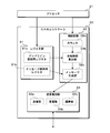
- FIG. 4 is a block diagram showing the configuration of the CAN controller 23 according to the present embodiment.
- the CAN controller 23 according to the present embodiment includes a register group 31, a control circuit 32, a transmission / reception circuit 33, and the like.
- the register group 31 is a storage area used for exchanging various data between the CAN controller 23 and the processor 21.
- the register group 31 includes a deadline holding register 31a and a message holding register 31b.
- the deadline holding register 31a is a register that stores the set value of the deadline time of the message to be transmitted.
- a plurality of deadline holding registers 31a may exist in the register group 31.
- the deadline time is set individually for, for example, the identification information attached to the message, the so-called CANID.
- the deadline time is set in the deadline holding register 31a by the processor 21 when the ECU 2 is started or the like.
- the processor 21 may set the deadline time each time the message is transmitted.
- the message holding register 31b is a register that stores a message to be transmitted to another ECU 2.
- the processor 21 When it becomes necessary to transmit a message to another ECU 2, the processor 21 generates a message to be transmitted and stores it in the message holding register 31b.
- the message stored in the message holding register 31b by the processor 21 may be a message according to a normal CAN communication standard, that is, a message in which the CAN ID is stored in the arbitration field.
- the message to be transmitted by the processor 21 is stored in the message holding register 31b, and a transmission instruction is given to the control circuit 32 to transmit the message of the CAN controller 23.
- the control circuit 32 of the CAN controller 23 is a circuit that controls the transmission and reception of messages.
- the control circuit 32 includes a counter 32a, a margin time calculation unit 32b, a message generation unit 32c, and the like.
- the counter 32a sets the time when the message transmission instruction is given from the processor 21 to 0 hours, and measures the elapsed time from this time.
- the time measured by the counter 32a corresponds to the standby time shown in FIG.
- the counter 32a is initialized by a transmission instruction from the processor 21, and is counted up according to the clock signal of the CAN controller 23.
- the margin time given to the message may be the time obtained by subtracting the waiting time from the deadline time, or may be the time obtained by subtracting the delay time from the deadline time.
- the margin time calculation unit 32b performs a process of calculating the margin time with respect to the deadline time based on the deadline time held in the deadline holding register 31a and the value of the counter 32a.
- the deadline holding register 31a stores the value of the counter corresponding to the deadline time.
- the margin time calculation unit 32b calculates the margin time by subtracting the value measured by the counter 32a from the value of the deadline holding register 31a. The measurement by the counter 32a and the calculation by the margin time calculation unit 32b are continuously performed until the transmission of this message is completed.
- the message generation unit 32c is a process of generating a message actually transmitted to the CAN bus 3 based on the message to be transmitted held in the message holding register 31b and the margin time calculated by the margin time calculation unit 32b. I do.
- the message generation unit 32c generates a message in which the margin time calculated by the margin time calculation unit 32b is stored in the arbitration field.
- the message generation unit 32c gives the generated message to the transmission / reception circuit 33.
- the transmission / reception circuit 33 of the CAN controller 23 performs transmission / reception of messages to the CAN bus 3 and arbitration processing when message transmissions collide.
- the transmission / reception circuit 33 includes a transmission unit 33a, a reception unit 33b, an arbitration unit 33c, and the like.
- the transmission unit 33a transmits the message by converting the digital message given from the control circuit 32 into an electric signal according to the CAN communication standard and outputting it to the CAN bus 3.
- the receiving unit 33b receives the message transmitted on the CAN bus 3 by sampling and acquiring the potential of the CAN bus 3.
- the arbitration unit 33c performs an arbitration process for determining which message is to be transmitted when a plurality of ECUs 2 simultaneously transmit a message to the CAN bus 3.
- the message with the smallest value stored in the arbitration field is given the right to send, and no other messages can be sent.
- the arbitration unit 33c determines that the transmission right to the own device has been given by the arbitration process, the arbitration unit 33c causes the transmission unit 33a to continuously transmit the message.
- the arbitration unit 33c determines that the transmission right has not been given, the arbitration unit 33c stops the message transmission by the transmission unit 33a. In this case, the arbitration unit 33c notifies the control circuit 32 that the message transmission has been stopped by the arbitration process. In response to this notification, the control circuit 32 regenerates the message by the message generation unit 32c after a predetermined waiting time, and attempts to retransmit the message.
- FIG. 5 is a schematic diagram for explaining the first message format.
- the message according to the CAN communication standard includes an arbitration field, a control field, a data field, a CRC (Cyclic Redundancy Check) field, an ACK field, and the like.
- both the spare time and the CANID are stored in the arbitration field.
- the margin time is stored on the upper bit side
- the CANID is stored on the lower bit side.
- the message generation unit 32c of the CAN controller 23 stores the information related to the margin time calculated by the margin time calculation unit 32b above the arbitration field of the transmitted message.
- the message generation unit 32c acquires the CANID set in the arbitration field of the message stored in the message holding register 31b, that is, the message generated by the processor 21.
- the message generation unit 32c stores the acquired CANID under the arbitration field of the transmission message.
- the extended format is adopted for the arbitration field of the message generated by the message generation unit 32c.
- the message arbitration field stored in the message holding register 31b by the processor 21 is in a normal format.
- the arbitration field is 11 bits in the normal format and 29 bits in the extended format.
- 18 bits are allocated to the information storage of the spare time and 11 bits are allocated to the information storage of the CANID for the arbitration field of the extended format.
- 18 bits can represent a margin time of about 500 msec.
- the 11 bits of the CANID can identify 2047 different messages.
- the bit allocation of the arbitration field is not limited to the above. If the number of message types is sufficiently small, the CANID bit allocation may be reduced and the spare time bit allocation may be increased. For example, it is conceivable to allocate 20 bits of the arbitration field to the spare time and 9 bits to the CANID. In this case, the information in the arbitration field can express a margin time of about 2 seconds and 511 message IDs. For example, it is conceivable to allocate 24 bits of the arbitration field to the spare time and 5 bits to the CANID. In this case, the information in the arbitration field can represent a margin time of about 33 seconds and 31 message IDs.
- FIG. 6 is a schematic diagram for explaining the second message format.
- the spare time and the device ID are stored in the arbitration field.
- the CANID is stored as part of the data field.
- the device ID is an ID uniquely defined for the device connected to the CAN bus 3 in the vehicle 1.
- a register for holding the device ID is provided in one of the register groups 31, and the processor 21 sets the device ID in this register at the time of initialization processing.
- the device ID is stored in advance in the storage unit 22, and the processor 21 reads the device ID from the storage unit 22 during the initialization process and sets it in the register group 31 of the CAN controller 23.
- the second message format since the CANID is stored in the data field of the message, a certain amount of free space is required in the data field.
- the device ID determined for each device of the vehicle 1 may be sufficiently smaller than the CANID that identifies the type of message. For example, by assigning 4 bits to the device ID for 29 bits of the extended format arbitration field, 15 devices are identified. In this case, 25 bits are allocated to the margin time, and the 25-bit data can express the margin time of about 67 seconds.
- FIG. 7 is a schematic diagram for explaining the third message format.
- the third message format only the information related to the spare time is stored in the arbitration field.
- the CANID is stored in the data field.
- the arbitration field may be in either normal format or extended format. If 11 bits is sufficient for the margin time, the normal format may be adopted for the arbitration field.
- the third message format when a plurality of messages with the same margin time are transmitted, it may be determined that the plurality of ECUs 2 have acquired the transmission right as a result of the arbitration process. In this case, since the plurality of ECUs 2 transmit the message, the transmission of the message is interrupted due to an error or the like. When the transmission of the message is interrupted, the ECU 2 attempts to retransmit this message after the elapse of a predetermined waiting time.
- the third message format in the communication system, the waiting time until the message is retransmitted by each ECU 2 is set to a different time. For a plurality of devices connected to one CAN bus 3, the waiting time until the message is retransmitted is always set to a different time. As a result, it is possible to prevent a plurality of messages having the same margin time from colliding even when retransmitted.
- the setting of the standby time of each ECU 2 can be stored in the storage unit 22.
- the standby time may be calculated based on information such as a device ID that is different for each ECU 2.
- a register for holding the standby time is provided in the register group 31 of the CAN controller 23, and the processor 21 sets the standby time in this register in the initialization process.
- FIG. 8 is a schematic diagram for explaining a message arbitration method by the communication system according to the present embodiment.
- the horizontal axis indicated by the thick arrow in the figure is the time axis representing the time t.
- the upper side of this time axis shows the timing of message transmission by the first ECU 2, and the lower side shows the timing of message transmission by the second ECU 2.
- the deadline time of the message transmitted by the first ECU 2 and the deadline time of the message transmitted by the second ECU 2 are set to be the same time.
- the first ECU 2 makes a request for transmitting a message from the processor 21 to the CAN controller 23.
- the message transmission by the first ECU 2 is waited until this is completed.
- the second ECU 2 makes a request for transmitting a message from the processor 21 to the CAN controller 23. Even at this time t1, the message transmission by the other ECU 2 is being performed on the CAN bus 3, and the message transmission by the second ECU 2 is on standby.
- the message transmission by the other ECU 2 ends at the time t2, and the message transmission by the first ECU 2 and the second ECU 2 is attempted. Since the two ECUs 2 attempted to transmit a message at the same time, the arbitration process is performed in each of the two ECUs 2.
- the deadline time for message transmission by the first ECU 2 is t3
- the deadline time for message transmission by the second ECU 2 is t4.
- the deadline time t3 comes earlier than the deadline time t4. Therefore, the margin time attached to the message transmitted by the first ECU 2 at time t2 is shorter than the margin time attached to the message transmitted by the second ECU 2.
- the first ECU 2 acquires the right to transmit a message, and the second ECU 2 needs to wait for the transmission of the message.
- the second ECU 2 attempts to retransmit its own message when the message transmission by the first ECU 2 is completed.
- FIG. 9 is a flowchart showing a procedure of message transmission processing performed by the CAN controller 23 of the ECU 2 according to the present embodiment.
- the CAN controller 23 according to the present embodiment performs initialization processing by receiving various set values stored in the register group 31 by the processor 21, for example, when the ECU 2 is started (step S1). After the initialization process is completed, the CAN controller 23 determines whether or not a message transmission request has been given from the processor 21 (step S2). When the transmission request is not given (S2: NO), the CAN controller 23 waits until the transmission request is given.
- the CAN controller 23 When a message transmission request is given from the processor 21 (S2: YES), the CAN controller 23 starts timing by the counter 32a of the control circuit 32 (step S3). Next, the CAN controller 23 determines whether or not a message can be transmitted to the CAN bus 3 (step S4). Here, the CAN controller 23 determines whether or not the message transmission is possible based on whether or not the message transmission by the other ECU 2 is performed on the CAN bus 3. When the message transmission is not possible (S4: NO), the CAN controller 23 waits until the message transmission becomes possible.
- the CAN controller 23 acquires the count value of the counter 32a at this point (step S5).
- the margin time calculation unit 32b of the CAN controller 23 calculates the margin time until the transmission is completed based on the deadline time held in the deadline holding register 31a for this message and the count value acquired in step S5. (Step S6).
- the message generation unit 32c of the CAN controller 23 generates a message in which the calculated margin time information is stored in the arbitration field.
- the CAN controller 23 attempts to transmit the generated message, and if it collides with the message transmission of another ECU 2, it performs an arbitration process (step S7).
- the CAN controller 23 determines whether or not the transmission of the message is completed (step S8). For example, when the transmission right is not acquired in the arbitration process or when the message transmission is not completed (S8: NO), the CAN controller 23 returns the process to step S4. When the transmission of the message is completed (S8: YES), the CAN controller 23 stops and resets the measurement of the counter 32a (step S9), and returns the process to step S2.
- the ECU 2 calculates, for a message to be transmitted to another ECU 2, a margin time until the time when the transmission of this message should be completed (deadline time).
- the ECU 2 attaches information according to the margin time calculated at the time of attempting to transmit the message to this message as information for arbitration processing, and attempts to transmit the message.
- the ECU 2 performs an arbitration process for determining which message transmission is prioritized.
- the ECU 2 performs arbitration processing so as to give priority to the transmission of the message having the short spare time.
- the communication system can perform arbitration processing in which the priority is changed according to the margin time of the message, and it is possible to prevent the transmission of a specific message from being continuously hindered for a long period of time.
- the ECU 2 attaches information according to the margin time of the message and identification information such as CANID or device ID to the message as information for arbitration processing. As a result, the ECU 2 can perform arbitration processing based on the identification information even when a plurality of messages having the same margin time are simultaneously transmitted.
- the ECU 2 When the message transmission by the plurality of ECUs 2 is duplicated and the message cannot be transmitted, the ECU 2 according to the present embodiment attempts to retransmit this message after the elapse of a predetermined waiting time. For a plurality of ECUs 2 connected to the CAN bus 3, the waiting time until the message is retransmitted is set to a different time for each ECU 2. As a result, even when messages having the same margin time are simultaneously transmitted and cannot be transmitted together, it is possible to provide a difference in the timing of retransmitting the messages.
- the ECU 2 includes a processor 21 and a CAN controller 23.
- the CAN controller 23 transmits and receives messages according to the processing of the processor 21, and also performs the above-mentioned calculation of the margin time, arbitration processing, and the like.
- the CAN controller 23 stores information regarding the time when the transmission of the message should be completed, that is, the deadline time, in the register group 31.
- the CAN controller 23 calculates the margin time of the message based on the time when the message transmission request is given from the processor 21 and the deadline time stored in the register group 31. As a result, the processor 21 and the program 22a or the like executed on the processor 21 do not need to calculate the margin time of the message, perform arbitration processing, or the like.
- the ECU 2 sends and receives a message according to the CAN communication standard.
- the ECU 2 stores the calculated information according to the margin time in the arbitration field of the CAN message.
- the smaller the value stored in the arbitration field the higher the priority, and the arbitration process is performed.
- the transmission of a message having a small stored value that is, a short margin time is prioritized.
- the communication system mounted on the vehicle 1 has been described as an example, but the application of the present technology is not limited to the in-vehicle communication system.
- a communication system having a similar configuration may be mounted on a moving body such as a ship or an airplane.
- a similar configuration may be adopted for a communication system provided in a factory, an office, or the like.
- the communication system according to the present embodiment transmits and receives messages according to the CAN communication standard, but other communication standards may be adopted.
- the communication standard adopted by the communication system is not limited to that for a bus type network, and may be for various network configurations such as a star type or a peer-to-peer type.
- the division of roles between the processor 21 and the CAN controller 23 included in the ECU 2 according to the present embodiment is not limited to the above.
- the processor 21 may calculate the margin time.
- the ECU 2 does not separately include the processor 21 and the CAN controller 23, but may include a processor incorporating the CAN controller 23.
- the CAN controller 23 measures the time by counting up the counter 32a, and calculates the margin time by subtracting the measurement time from the deadline time held in the deadline holding register 31a. ..
- the CAN controller 23 may set the deadline time as the initial value of the counter 32a and count down the counter 32a to acquire the margin time.
- the ECU 2 that transmits a message in which the spare time is stored in the arbitration field and the ECU 2 that transmits a message in which the conventional CANID is stored in the arbitration field coexist as described above.
- the CAN controller 23 performs the arbitration process by treating the information as mere binary digital information.
- the CAN controller 23 may give priority to the digital information stored in the arbitration field having a small numerical value.
- the processor 21 can select whether the information to be stored in the arbitration field of the message to be transmitted is a margin time or a CAN ID.
- the register group 31 of the CAN controller 23 according to the second modification includes a register for setting the selection of whether to attach the spare time or the CAN ID to the message.
- the processor 21 sets this register and gives a message transmission request to the CAN controller 23.
- the CAN controller 23 stores either the spare time or the CAN ID in the arbitration field according to the setting set in the register, and transmits a message.
- the transmission of a message in which the spare time is stored in the arbitration field and the transmission of the conventional message in which the CANID is stored can be mixed. is there. Therefore, it is possible to introduce the arbitration process based on the spare time only in some ECUs 2 included in the existing communication system.
- the ECU 2 may use the arbitration field in the normal format when storing the CANID, and may use the arbitration field in the extended format when storing the spare time. In this case, in the arbitration process, a message having a normal format arbitration field may be prioritized.
- the second embodiment relates to a gateway 4 that relays message transmission / reception between a plurality of CAN buses 3.
- the gateway 4 according to the second embodiment calculates the spare time of a message relayed and transmitted from another CAN bus 3 in consideration of the spare time attached to the message received by one CAN bus 3.
- FIG. 10 is a block diagram showing a configuration of the gateway 4 according to the second embodiment.
- the gateway 4 according to the second embodiment is configured to include a processor 41, a storage unit (storage) 42, a plurality of CAN controllers 23, and the like.
- the processor 41 reads and executes the program 42a stored in the storage unit 42 to perform various processes such as a process of relaying a message between a plurality of CAN buses 3.
- the storage unit 42 is configured by using a non-volatile memory element such as a flash memory or EEPROM.
- the storage unit 42 stores various data including the program 42a executed by the processor 41.
- the program 42a may be written to the storage unit 42, for example, at the manufacturing stage of the gateway 4.
- the gateway 4 may acquire what is distributed by a remote server device or the like by communication.
- the gateway 4 may read the program 42a recorded on a recording medium such as a memory card or an optical disk and store it in the storage unit 42.
- the writing device may read what has been recorded on the recording medium and write it in the storage unit 42 of the gateway 4.
- the program 42a may be provided in a mode of distribution via a network, or may be provided in a mode recorded on a recording medium.
- the gateway 4 includes two CAN controllers 23.
- the gateway 4 may include three or more CAN controllers 23.
- a CAN bus 3 is connected to each of the CAN controllers 23, and messages are transmitted and received via the CAN bus 3.
- the CAN controller 23 may be the same as the CAN controller 23 included in the ECU 2.
- the CAN controller 23 converts a transmission message given by the processor 41 into an electric signal according to the CAN communication standard and outputs the message to the CAN bus 3 to transmit the message to another in-vehicle device.
- the CAN controller 23 receives a message from another in-vehicle device by sampling and acquiring the potential of the CAN bus 3, and gives the received message to the processor 41.
- the processor 41 reads and executes the program 42a stored in the storage unit 42, so that the initialization processing unit 41a, the transmission request processing unit 41b, the relay processing unit 41c, and the like are the processor 41. It is realized as a software-like functional block.
- the initialization processing unit 41a performs initialization processing of the CAN controller 23 at the time of starting the gateway 4 or the like.
- the transmission request processing unit 41b requests the transmission of this message by generating a message to be transmitted and giving it to the CAN controller 23.
- the relay processing unit 41c performs a process of transmitting a message received by one CAN controller 23 from another CAN controller 23.
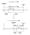
- FIG. 11 is a schematic diagram for explaining the propagation of the margin time and the deadline time of the message.
- the upper part of FIG. 11 shows a timing chart when the ECU 2 first transmits a message.
- the deadline time td is the time when the set deadline time elapses with respect to the transmission request time t0 at the time when the message transmission request is given from the processor 21 of the ECU 2 to the CAN controller 23.
- the message transmission of the ECU 2 is performed at the time t1 when a certain amount of waiting time has elapsed from the transmission request time t0.
- the transmission of this message is completed at time t2 when a predetermined transmission time depending on the message length has elapsed.
- the margin time stored in the arbitration field of the message is the time from the time t1 to the deadline time td.
- the lower part of FIG. 11 shows a timing chart when the gateway 4 relays a message.
- the gateway 4 receives a message transmitted by the ECU 2 connected to one CAN bus 3, and transmits this message from another CAN bus 3 to relay a message between the two CAN buses 3.
- the gateway 4 acquires the spare time stored in the arbitration field of the received message.
- the gateway 4 calculates the time obtained by subtracting the transmission time of this message and the time required for the internal processing of the gateway 4 from the acquired spare time.
- the calculated time can be used as a new deadline time when transmitting a relay message.
- the time required for the internal processing of the gateway 4 is set to 0, and the processor 41 of the gateway 4 that has received the message at time t2 requests the CAN controller 23 to transmit this message at time t2. Therefore, the propagated deadline time is the time from the time t2 to the deadline time td.
- the processor 41 of the gateway 4 gives a received message given from one CAN controller 23 to another CAN controller 23 as a transmitted message. At this time, the processor 41 sets a new deadline time calculated from the margin time stored in the received message in the deadline holding register 31a of the other CAN controller 23, and requests the transmission of the message. Upon receiving the transmission request, the CAN controller 23 performs message transmission processing and arbitration processing using the deadline time newly set in the deadline holding register 31a by the processor 41.
- the message transmission processing and arbitration processing performed here are the same as the above-mentioned processing performed by the CAN controller 23 of the ECU 2.
- the gateway 4 may be able to select whether or not to propagate the spare time of the received message to the relay message. For example, the gateway 4 may store the setting of whether or not to propagate the spare time for each CANID of the message in the storage unit 42. If the spare time is not propagated, the gateway 4 sets a new deadline time for the relayed message. Further, even when the gateway 4 propagates the margin time, the gateway 4 may determine a new deadline time by appropriately increasing or decreasing the margin time acquired from the received message.
- the message of the gateway 4 is transmitted at the time t3 when a certain waiting time has elapsed from the transmission request time t2.
- the transmission of this message is completed at the time t4 when a predetermined transmission time depending on the message length has elapsed.
- the margin time stored in the arbitration field of the message is the time from the time t3 to the deadline time td.
- the CAN controller 23 transmits a message using the deadline time initially set in the deadline holding register 31a by the processor 21.
- the deadline time is calculated every time the processor 21 relays the message, the calculated deadline time is set in the deadline holding register 31a, and the CAN controller 23 is requested to transmit the message. ..
- the CAN controller 23 of the gateway 4 transmits a message using the deadline time set each time.
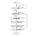
- FIG. 12 is a flowchart showing a procedure of message relay processing performed by the gateway 4 according to the second embodiment.
- the processor 41 of the gateway 4 according to the second embodiment determines whether or not a message has been received by any CAN controller 23 (step S21). When the message is not received (S21: NO), the processor 41 waits until the message is received by any CAN controller 23.
- the processor 41 determines whether or not to propagate the spare time attached to the received message when relaying the received message (step S22). ). Whether or not to propagate the margin time is determined based on, for example, the CANID attached to the received message.
- the processor 41 sets a message to be relayed to the message holding register 31b of the CAN controller 23 which is the relay destination, and gives a transmission request for this message (step S26). End the process.
- the processor 41 When propagating the margin time (S22: YES), the processor 41 acquires the information regarding the margin time stored in the arbitration field of the received message (step S23). The processor 41 calculates a new deadline time based on the acquired spare time, the time required for transmitting this message, the time required for internal processing of the gateway 4, and the like (step S24). The processor 41 sets the calculated deadline time in the deadline holding register 31a for the CAN controller 23 different from the CAN controller 23 that received the message (step S25). The processor 41 sets a message to be relayed to the message holding register 31b of the CAN controller 23, gives a transmission request for this message (step S26), and ends the process.
- the gateway 4 to which a plurality of CAN buses 3 are connected relays a message received by one CAN bus 3 from another CAN bus 3. I do.
- the gateway 4 acquires information according to the spare time stored in the arbitration field of the received message.
- the gateway 4 calculates the deadline time when relaying this message based on the spare time acquired from the received message.
- the gateway 4 calculates the margin time of the message transmitted by the relay based on the calculated deadline time.
- Each device in this system includes a computer including a microprocessor, ROM, RAM, and the like.
- An arithmetic processing unit such as a microprocessor reads a computer program including a part or all of each step of a sequence diagram or a flowchart from a storage unit such as a ROM or a RAM and executes the computer program as shown in FIGS. 9 and 12 respectively. You can do it.
- the computer programs of these plurality of devices can be installed from an external server device or the like. Further, the computer programs of these plurality of devices are distributed in a state of being stored in a recording medium such as a CD-ROM, a DVD-ROM, or a semiconductor memory, respectively.
- Vehicle 2 ECU (communication device) 3 CAN bus (communication line) 4 Gateway (communication device) 21 Processor 21a Initialization processing unit 21b Transmission request processing unit 22 Storage unit 22a Program 23 CAN controller (communication controller) 31 Register group (storage unit) 31a Deadline holding register 31b Message holding register 32 Control circuit 32a Counter 32b Margin time calculation unit (calculation unit) 32c Message generation unit 33 Transmission / reception circuit 33a Transmission unit 33b Reception unit 33c Mediation unit 41 Processor (acquisition unit) 41a Initialization processing unit 41b Transmission request processing unit 41c Relay processing unit 42 Storage unit 42a Program
Landscapes
- Engineering & Computer Science (AREA)
- Computer Networks & Wireless Communication (AREA)
- Signal Processing (AREA)
- Small-Scale Networks (AREA)
Abstract
メッセージの送信が長期間に亘って阻害され続けることを抑制できる通信装置、通信システム及びメッセージ調停方法を提供する。 本実施の形態に係る通信装置は、共有の通信線に接続された他の装置との間でメッセージを送受信する通信装置であって、送信すべきメッセージについて、該メッセージの送信を完了すべき時間までの余裕時間を算出する算出部と、前記算出部が算出した余裕時間に応じた情報を前記メッセージに付して送信する送信部と、メッセージに付された前記情報に基づいて、前記通信線に対するメッセージ送信が重複した際の調停を行う調停部とを備え、前記調停部は、前記通信線に対して重複して送信された複数のメッセージについて、余裕時間が少ないメッセージを優先する調停を行う。
Description
本開示は、共通の通信線を介してメッセージを送受信する通信装置、通信システム及びメッセージ調停方法に関する。
従来、車両にはECU(Electronic Control Unit)等の装置が複数搭載されている。これら複数の装置は通信線を介して相互に接続され、メッセージの送受信を行うことにより情報を交換し、協働により車両の種々の機能を実現している。車両内の通信には、CAN(Controller Area Network)の通信規格が広く採用されている。
特許文献1においては、車両内に配されるCANの通信線を多系統に分割した場合に、通信線間の通信を効率よく調停することが期待できる車載ネットワーク拡張装置が提案されている。この車載ネットワーク拡張装置は、通信線間で通信の衝突が生じた際に、メッセージに付与された優先度に基づいて通信線間の通信を調停する回路を備えている。
CANの通信規格においては、通信線に対するメッセージの送信が衝突した場合に、各通信装置にて調停処理(アービトレーション(arbitration)処理)が行われる。調停処理の結果、いずれか1つのメッセージの送信が許可され、これ以外のメッセージの送信は中止される。いずれのメッセージ送信を優先するかは、メッセージに対して付されたIDに基づいて決定される。CANのIDは、その値が小さいほど優先度が高いことを示す。CANのIDは、例えば通信装置又は通信システムの設計段階等において静的に決定される。従来のCANの調停処理においては、優先度が低いメッセージの送信が、優先度が高いメッセージの送信により阻害され続ける虞があった。
本開示は、斯かる事情に鑑みてなされたものであって、その目的とするところは、メッセージの送信が長期間に亘って阻害され続けることを抑制できる通信装置、通信システム及びメッセージ調停方法を提供することにある。
本態様に係る通信装置は、共有の通信線に接続された他の装置との間でメッセージを送受信する通信装置であって、送信すべきメッセージについて、該メッセージの送信を完了すべき時間までの余裕時間を算出する算出部と、前記算出部が算出した余裕時間に応じた情報を前記メッセージに付して送信する送信部と、メッセージに付された前記情報に基づいて、前記通信線に対するメッセージ送信が重複した際の調停を行う調停部とを備え、前記調停部は、前記通信線に対して重複して送信された複数のメッセージについて、余裕時間が少ないメッセージを優先する調停を行う。
本願は、このような特徴的な処理部を備える通信装置として実現することができるだけでなく、かかる特徴的な処理をステップとするメッセージ調停方法として実現したり、かかるステップをコンピュータに実行させるためのコンピュータプログラムとして実現したりすることができる。通信装置の一部又は全部を実現する半導体集積回路として実現したり、通信装置を含むその他の装置又はシステムとして実現したりすることができる。
上記によれば、メッセージの送信が長期間に亘って阻害され続けることを抑制できる。
[本開示の実施の形態の説明]
最初に本開示の実施態様を列記して説明する。以下に記載する実施形態の少なくとも一部を任意に組み合わせてもよい。
最初に本開示の実施態様を列記して説明する。以下に記載する実施形態の少なくとも一部を任意に組み合わせてもよい。
(1)本態様に係る通信装置は、共有の通信線に接続された他の装置との間でメッセージを送受信する通信装置であって、送信すべきメッセージについて、該メッセージの送信を完了すべき時間までの余裕時間を算出する算出部と、前記算出部が算出した余裕時間に応じた情報を前記メッセージに付して送信する送信部と、メッセージに付された前記情報に基づいて、前記通信線に対するメッセージ送信が重複した際の調停を行う調停部とを備え、前記調停部は、前記通信線に対して重複して送信された複数のメッセージについて、余裕時間が少ないメッセージを優先する調停を行う。
本態様にあっては、通信装置が送信するメッセージについて、このメッセージの送信を完了すべき時間までの余裕時間を算出する。通信装置は、メッセージの送信を試みる時点で算出された余裕時間に応じた情報を、調停用情報としてこのメッセージに付して送信を試みる。自身のメッセージ送信と、共通の通信線に接続された他の通信装置のメッセージ送信とが同時的に行われてメッセージ送信の衝突が生じた場合、通信装置はいずれのメッセージの送信を優先して行うかを決定する調停処理を行う。このときに通信装置は、各メッセージに付された余裕時間の情報に基づいて、余裕時間が少ないメッセージの送信を優先するように調停処理を行う。これにより、メッセージの余裕時間に応じて優先度を変動させた調停処理が可能となり、特定のメッセージの送信が長期間に亘って阻害され続けることを抑制できる。
(2)前記送信部は、前記算出部が算出した余裕時間に応じた情報と、メッセージを識別する識別情報又は装置を識別する識別情報とを前記メッセージに付して送信することが好ましい。
本態様にあっては、メッセージの余裕時間に応じた情報と、メッセージの識別情報又は装置の識別情報とを、通信装置が調停用情報としてメッセージに付して送信する。これにより、余裕時間が同じ値の複数のメッセージが同時的に送信された場合であっても、通信装置は識別情報に基づく調停処理を行うことができる。
(3)プロセッサと、前記算出部、前記送信部及び前記調停部を有し、前記プロセッサの処理に応じて前記通信線に対するメッセージの送受信を行う通信コントローラとを備え、前記通信コントローラは、メッセージの送信を完了すべき時間に係る情報を記憶する記憶部を有し、前記算出部は、前記プロセッサからメッセージの送信要求を与えられた時点、及び、前記記憶部に記憶した情報に基づいて前記余裕時間を算出することが好ましい。
本態様にあっては、通信装置がプロセッサ及び通信コントローラを備える。通信コントローラは、プロセッサの処理に応じてメッセージの送受信を行うと共に、上述の余裕時間の算出及びメッセージの調停等の処理を行う。通信コントローラは、メッセージの送信を完了すべき時間に関する情報を記憶する。通信コントローラは、プロセッサからメッセージの送信要求が与えられた時点、及び、記憶部に記憶した時間に関する情報に基づいて、メッセージの余裕時間を算出する。これにより、プロセッサ及びこのプロセッサ上で実行されるアプリケーションプログラム等は、メッセージの余裕時間の算出及び調停等の処理を行う必要がない。
(4)前記メッセージは、CAN(Controller Area Network)の通信規格に従うメッセージであり、前記送信部は、前記余裕時間に応じた情報を、CANのメッセージのアービトレーションフィールドに格納して送信することが好ましい。
本態様にあっては、通信装置がCANの通信規格に従ってメッセージの送受信を行う。通信装置は、算出した余裕時間に応じた情報を、CANメッセージのアービトレーションフィールドに格納して送信する。CANの通信規格では、アービトレーションフィールドに格納された値が小さいほど優先度が高いものとしてメッセージの調停(アービトレーション)が行われる。アービトレーションフィールドに余裕時間に応じた情報を格納することで、格納された値が小さい、即ち余裕時間が短いメッセージの送信が優先される。
(5)複数の通信線に接続され、一の通信線にて受信したメッセージを他の通信線から送信する処理を行う中継部と、前記一の通信線にて受信したメッセージに付された前記余裕時間に応じた情報を取得する取得部とを備え、前記算出部は、前記取得部が取得した情報に基づいて、中継するメッセージの余裕時間を算出することが好ましい。
本態様にあっては、通信装置は複数の通信線に接続され、一の通信線にて受信したメッセージを他の通信線から送信するメッセージの中継処理を行ってもよい。この場合に通信装置は、一の通信線にて受信したメッセージに付された余裕時間に応じた情報を取得する。このメッセージを中継のために他の通信線から送信する場合、通信装置は、取得した情報に基づいて中継するメッセージの余裕時間を算出する。例えば通信装置は、取得した情報に基づく余裕時間をこのメッセージの送信を完了すべき時間として、中継するメッセージの余裕時間を算出することができる。これにより、メッセージが一又は複数の通信装置にて中継される場合に、余裕時間を伝播させてメッセージの送信及び調停等の処理を行うことができる。
(6)前記送信部は、前記調停部による調停のための情報として、前記算出部が算出した余裕時間に係る情報、又は、前記メッセージに対して静的に定められた識別情報のいずれかを選択的にメッセージに付して送信することが好ましい。
本態様にあっては、通信装置は上記の余裕時間に係る情報を付したメッセージ送信と、静的に定められた識別情報を付したメッセージ送信とを選択的に行うことが可能である。各通信装置による調停は、余裕時間に係る情報と、静的に定められた識別情報とを区別することなく、いずれも同様の数値的な情報として扱うことで可能である。通信装置は、余裕時間に係る情報又は識別情報のいずれを付してメッセージを送信するかを適宜に選択することができる。
(7)本態様に係る通信システムは、共有の通信線に接続された複数の通信装置がメッセージを送受信する通信システムであって、前記通信装置は、送信すべきメッセージについて、該メッセージの送信を完了すべき時間までの余裕時間を算出する算出部と、前記算出部が算出した余裕時間に応じた情報を前記メッセージに付して送信する送信部と、メッセージに付された前記情報に基づいて、前記通信線に対するメッセージ送信が重複した際の調停を行う調停部とを備え、前記調停部は、前記通信線に対して重複して送信された複数のメッセージについて、余裕時間が少ないメッセージを優先する調停を行う。
本態様にあっては、態様(1)と同様に、メッセージの余裕時間に応じて優先度を変動させた調停処理が可能となり、特定のメッセージの送信が長期間に亘って阻害され続けることを抑制できる。
(8)前記送信部は、メッセージを送信できなかった場合に、所定の待機時間の経過後に前記メッセージを再送信し、前記待機時間は、前記通信装置毎に異なる時間が設定されていることが好ましい。
本態様にあっては、複数の通信装置によるメッセージの送信が重複し、調停処理によりメッセージが送信できなかった場合等に、通信装置は所定の待機時間の経過後にこのメッセージの再送信を試みる。共通の通信線に接続された複数の通信装置について、メッセージの再送信までの待機時間は通信装置毎に異なる時間が設定される。これにより、余裕時間が同じ値の複数のメッセージが同時的に送信されて共に送信できなかった場合であっても、次のメッセージ送信のタイミングに差を設けることができる。
(9)前記複数の通信装置には、前記余裕時間に応じた情報を前記調停部の調停に用いる情報としてメッセージに付す通信装置と、メッセージに対して静的に定められた識別情報を前記調停部の調停に用いる情報として前記メッセージに付す通信装置とを含むことが好ましい。
本態様にあっては、余裕時間に応じた情報を付してメッセージを送信する通信装置と、静的に定められた識別情報を付してメッセージを送信する通信装置とが通信システム中に混在可能である。
(10)本態様に係るメッセージ調停方法は、共通の通信線に接続された複数の通信装置によるメッセージ送信が重複した際の調停を行うメッセージ調停方法であって、各通信装置が、送信すべきメッセージについて、該メッセージの送信を完了すべき時間までの余裕時間を算出し、算出した余裕時間に応じた情報を前記メッセージに付して送信し、メッセージに付された前記情報に基づき、前記通信線に対して重複して送信された複数のメッセージについて、余裕時間が少ないメッセージを優先する調停を行う。
本態様にあっては、態様(1)と同様に、メッセージの余裕時間に応じて優先度を変動させた調停処理が可能となり、特定のメッセージの送信が長期間に亘って阻害され続けることを抑制できる。
[本開示の実施形態の詳細]
本開示の実施形態に係る通信システムの具体例を、以下に図面を参照しつつ説明する。本開示はこれらの例示に限定されるものではなく、請求の範囲によって示され、請求の範囲と均等の意味及び範囲内でのすべての変更が含まれることが意図される。
本開示の実施形態に係る通信システムの具体例を、以下に図面を参照しつつ説明する。本開示はこれらの例示に限定されるものではなく、請求の範囲によって示され、請求の範囲と均等の意味及び範囲内でのすべての変更が含まれることが意図される。
<システム概要>
図1は、本実施の形態に係る通信システムの概要を説明するための模式図である。本実施の形態に係る通信システムは、車両1に搭載された複数のECU2がCANの通信規格に従ってメッセージの送受信を行うシステムである。複数のECU2は、車両1内に配されたCANバス3にそれぞれ接続される。1つのCANバス3には、数個から十数個程度のECU2が接続され得る。車両1には複数のCANバス3が設けられていてもよい。この場合には、車両1にゲートウェイ4が搭載される。ゲートウェイ4は、複数のCANバス3が接続され、これら複数のCANバス3の間のメッセージの送受信を中継する。図示の例では、車両1には2つのCANバス3が設けられている。2つのCANバス3は、ゲートウェイ4に接続されている。各CANバス3には、それぞれ4つのECU2が接続されている。8つのECU2は、2つのCANバス3及び1つのゲートウェイ4を介して、相互にメッセージを送受信することができる。なお、通信システムに含まれるECU2の数、CANバス3の数、ゲートウェイ4の数、装置の接続態様及びネットワークの構成等は、図示のものに限らない。
図1は、本実施の形態に係る通信システムの概要を説明するための模式図である。本実施の形態に係る通信システムは、車両1に搭載された複数のECU2がCANの通信規格に従ってメッセージの送受信を行うシステムである。複数のECU2は、車両1内に配されたCANバス3にそれぞれ接続される。1つのCANバス3には、数個から十数個程度のECU2が接続され得る。車両1には複数のCANバス3が設けられていてもよい。この場合には、車両1にゲートウェイ4が搭載される。ゲートウェイ4は、複数のCANバス3が接続され、これら複数のCANバス3の間のメッセージの送受信を中継する。図示の例では、車両1には2つのCANバス3が設けられている。2つのCANバス3は、ゲートウェイ4に接続されている。各CANバス3には、それぞれ4つのECU2が接続されている。8つのECU2は、2つのCANバス3及び1つのゲートウェイ4を介して、相互にメッセージを送受信することができる。なお、通信システムに含まれるECU2の数、CANバス3の数、ゲートウェイ4の数、装置の接続態様及びネットワークの構成等は、図示のものに限らない。
ECU2は、例えば例えば車両1のエンジンの動作を制御するECU、ドアのロック/アンロックを制御するECU、ライトの点灯/消灯を制御するECU、エアバッグの動作を制御するECU、及び、ABS(Antilock Brake System)の動作を制御するECU等の種々のECUが含まれ得る。なお、本実施の形態においては、CANバス3を介した通信を行う通信装置としてECU2及びゲートウェイ4を挙げるが、通信装置はこれらに限るものではない。
CANの通信規格に従うメッセージには、CANIDと呼ばれる識別情報が、アービトレーションフィールドと呼ばれるメッセージの先頭領域に格納される。CANIDは、このメッセージに含まれるデータの種別等を示すと共に、このメッセージの優先度を示す情報である。CANIDは、その値が小さいほど優先度が高いメッセージであることを示す。複数のECU2がCANバス3に対して同時的にメッセージの送信を試みた場合、CANの通信システムではメッセージのアービトレーションフィールドに格納されたCANIDの値に基づくアービトレーション(調停)処理が各ECU2にて行われる。アービトレーション処理の結果、最も優先度が高い1つのメッセージが送信を許可され、これ以外のメッセージは送信を待機する必要がある。CANIDは、車両1、通信システム又はECU2の設計段階等において設計者により決定される静的な値である。
本実施の形態に係る通信システムでは、メッセージのアービトレーションフィールドに格納する値を各ECU2が動的に変化させることによって、メッセージの優先度を動的に変化させる。詳しくは、本実施の形態に係るECU2は、メッセージの送信を完了すべき時間に対する余裕時間を算出し、算出した余裕時間に係る情報をメッセージのアービトレーションフィールドに格納して送信する。余裕時間は、その値が小さいほど余裕が少ないことを示す。CANの通信規格に従ってアービトレーション処理が行われることによって、余裕時間が少ないメッセージが優先して送信されることとなる。
図2は、メッセージの余裕時間を説明するための模式図であり、横軸を時刻tとするメッセージ送信のタイミングチャートを示している。本実施の形態に係るECU2は、例えば所定の送信周期Tでメッセージ送信を繰り返し行っている。図示の例は、ECU2の1番目のメッセージの送信要求時刻をt0とし、2番目のメッセージの送信要求時刻をt1としている。送信周期T=t1-t0である。各メッセージには、送信要求時刻からメッセージの送信を完了すべき時間がデッドライン時間TDとして予め設定されている。図示の例では、送信要求時刻t0に対してデッドライン時間TDが経過した時刻をデッドライン時刻tdとしている。
ECU2は、送信要求時刻t0においてメッセージ送信を試みたとしても、自身のメッセージ送信が待機させられる場合がある。これは例えば、既に他のECU2によるメッセージ送信が行われている場合、又は、他のECU2が同時的にメッセージ送信を試みてアービトレーション処理により自身のメッセージ送信の権利が得られなかった場合等である。このような場合にECU2は、所定の待機時間の後にメッセージの再送信を試みる。図示の例では、待機時間が経過した送信開始時刻tsの時点でECU2がメッセージの送信権利を獲得し、送信を開始している。メッセージの送信時間は、メッセージのデータサイズに依存し、図示の例では送信終了時刻teの時点でECU2がメッセージの送信を終了している。送信要求時刻t0からメッセージの送信終了時刻teまでが、このメッセージの遅延時間に相当する。
本実施の形態に係る通信システムにおいては、ECU2が送信する各メッセージに対してデッドライン時間TDが予め設定されている。デッドライン時間TDは、メッセージの送信要求時刻t0からこのメッセージの送信を完了すべき時間を規定した設定値である。送信要求時刻t0にデッドライン時間TDを加えた時点をデッドライン時刻tdとすると、メッセージの送信終了時刻teはデッドライン時刻tdより先である必要がある。ただし、デッドライン時刻tdよりメッセージの送信開始時刻tsが先であればよいとする規則での運用であってもよい。デッドライン時間TDは、このメッセージの送信周期T以下の時間が設定される。
本実施の形態に係る通信システムにおいては、メッセージの送信開始時刻からデッドライン時刻tdまでの時間を余裕時間とする。ECU2は、送信すべきメッセージの余裕時間を算出する。ECU2は、送信開始時刻tsにてメッセージの送信権を獲得した際に、このメッセージのアービトレーションフィールドに算出した余裕時間を格納して送信を行う。ECU2が算出する余裕時間及びメッセージに格納される余裕時間は、実時間を数値化したものであってよいが、本実施の形態においては通信処理に用いられるクロック信号のクロック数で表される。例えばクロック周期が2μ秒であり、実時間が500μ秒である場合、クロック数は250となる。クロック周期に関する情報は、複数のECU2の間で共有される。メッセージに格納される余裕時間に関する情報は、図2に示すメッセージの送信開始時刻tsからデッドライン時刻tdまでの時間に応じたクロック数とすることができる。又は、メッセージの送信終了時刻teからデッドライン時刻tdまでの時間に応じたクロック数をメッセージに格納してもよい。
各ECU2が同様にしてメッセージのアービトレーションフィールドに余裕時間を格納して送信を行う。デッドライン時刻tdまでの余裕時間が短いほど、メッセージに格納される余裕時間の値は小さいものとなる。CANのアービトレーション処理においては、メッセージのアービトレーションフィールドに格納された値が小さいほど、優先度が高いメッセージとして扱われる。即ち、本実施の形態に係る通信システムでは、余裕時間が短いメッセージが優先して送信される。
<装置構成>
図3は、本実施の形態に係るECU2の構成を示すブロック図である。本実施の形態に係るECU2は、プロセッサ21、記憶部(ストレージ)22及びCANコントローラ23等を備えて構成されている。プロセッサ21は、記憶部22に記憶されたプログラム22aを読み出して実行することにより、車両1の制御処理等の種々の処理を行う。本実施の形態においてプロセッサ21は、制御処理等において他のECU2へのメッセージ送信が必要となった場合に、送信すべきメッセージをCANコントローラ23へ与えて、このメッセージの送信を指示する。
図3は、本実施の形態に係るECU2の構成を示すブロック図である。本実施の形態に係るECU2は、プロセッサ21、記憶部(ストレージ)22及びCANコントローラ23等を備えて構成されている。プロセッサ21は、記憶部22に記憶されたプログラム22aを読み出して実行することにより、車両1の制御処理等の種々の処理を行う。本実施の形態においてプロセッサ21は、制御処理等において他のECU2へのメッセージ送信が必要となった場合に、送信すべきメッセージをCANコントローラ23へ与えて、このメッセージの送信を指示する。
記憶部22は、例えばフラッシュメモリ又はEEPROM(Electrically Erasable Programmable Read Only Memory)等の不揮発性のメモリ素子を用いて構成されている。記憶部22は、プロセッサ21が実行する各種のプログラム、及び、プロセッサ21の処理に必要な各種のデータを記憶する。本実施の形態において記憶部22は、プロセッサ21が実行するプログラム22aを記憶している。
プログラム22aは、例えばECU2の製造段階において記憶部22に書き込まれてもよい。例えばプログラム22aは、遠隔のサーバ装置などが配信するものをECU2が通信にて取得してもよい。例えばプログラム22aは、メモリカード又は光ディスク等の記録媒体に記録されたプログラム22aをECU2が読み出して記憶部22に記憶してもよい。例えばプログラム22aは、記録媒体に記録されたものを書込装置が読み出してECU2の記憶部22に書き込んでもよい。プログラム22aは、ネットワークを介した配信の態様で提供されてもよく、記録媒体に記録された態様で提供されてもよい。
CANコントローラ23は、CANバス3を介したメッセージの送受信を行う。CANコントローラ23は、例えば1つのIC(Integrated Circuit)として構成され得る。CANコントローラ23は、車両1内に配されたCANバス3を介して他のECU2及びゲートウェイ4等に接続され、これら他の車載装置との間でCANの通信規格に従う通信を行う。CANコントローラ23は、プロセッサ21から与えられた送信用のメッセージをCANの通信規格に応じた電気信号に変換してCANバス3へ出力することにより、他の車載装置へのメッセージ送信を行う。CANコントローラ23は、CANバス3の電位をサンプリングして取得することにより他の車載装置からのメッセージを受信し、受信したメッセージをプロセッサ21へ与える。
本実施の形態に係るCANコントローラ23は、送信すべきメッセージのデッドライン時間TDに対する余裕時間を算出する。CANコントローラ23は、算出した余裕時間に係る情報を、メッセージのアービトレーションフィールドに格納して送信することができる。CANコントローラ23は、自身のメッセージ送信と、他のECU2のメッセージ送信とが衝突した場合に、CANの通信規格に従うアービトレーション処理を行う。これによりCANコントローラ23は、余裕時間が短いメッセージを優先して送信する。CANコントローラ23は、上記の余裕時間に係る情報と、従来のCANIDとのいずれかを選択的にアービトレーションフィールドに格納してメッセージ送信を行うことが可能な構成であってよい。
本実施の形態に係るECU2では、記憶部22に記憶されたプログラム22aをプロセッサ21が読み出して実行することにより、初期化処理部21a及び送信要求処理部21b等がプロセッサ21にソフトウェア的な機能ブロックとして実現される。初期化処理部21aは、ECU2の起動時等に、CANコントローラ23の初期化処理を行う。初期化処理には、例えばメッセージ毎のデッドライン時間の設定処理が含まれ得る。送信要求処理部21bは、例えば車両1の走行制御等の処理において他のECU2へ送信すべきメッセージが生じた場合に、このメッセージを送信する処理を行う。送信要求処理部21bは、送信すべきメッセージを生成してCANコントローラ23へ与えることによって、このメッセージの送信を要求する。
図4は、本実施の形態に係るCANコントローラ23の構成を示すブロック図である。図4においては、CANコントローラ23のメッセージ送信に関する機能ブロックを主に図示し、メッセージ受信に関する機能ブロックの図示は省略している。本実施の形態に係るCANコントローラ23は、レジスタ群31、制御回路32及び送受信回路33等を備えている。レジスタ群31は、CANコントローラ23とプロセッサ21との間の種々のデータ授受に用いられる記憶領域である。本実施の形態においてレジスタ群31には、デッドライン保持用レジスタ31a及びメッセージ保持用レジスタ31bが含まれている。
デッドライン保持用レジスタ31aは、送信すべきメッセージのデッドライン時間の設定値を記憶するレジスタである。ECU2が複数種類のメッセージを送信する可能性がある場合、レジスタ群31にはデッドライン保持用レジスタ31aが複数存在してもよい。デッドライン時間は、例えばメッセージに付される識別情報、いわゆるCANIDに対して個別に設定される。本実施の形態においてデッドライン保持用レジスタ31aへのデッドライン時間の設定は、ECU2の起動時等にプロセッサ21によって行われる。ただし、プロセッサ21がメッセージ送信の都度にデッドライン時間を設定してもよい。
メッセージ保持用レジスタ31bは、他のECU2に対して送信すべきメッセージを記憶するレジスタである。プロセッサ21は、他のECU2に対してメッセージ送信を行う必要が生じた場合に、送信すべきメッセージを生成してメッセージ保持用レジスタ31bに格納する。プロセッサ21がメッセージ保持用レジスタ31bに格納するメッセージは、通常のCANの通信規格に従うメッセージ、即ちアービトレーションフィールドにCANIDが格納されたメッセージであってよい。プロセッサ21が送信すべきメッセージをメッセージ保持用レジスタ31bに格納し、制御回路32に対して送信指示を与えることによって、CANコントローラ23のメッセージ送信が行われる。
CANコントローラ23の制御回路32は、メッセージの送受信に関する制御を行う回路である。制御回路32は、カウンタ32a、余裕時間算出部32b及びメッセージ生成部32c等を備えて構成されている。カウンタ32aは、プロセッサ21からメッセージの送信指示が与えられた時点を0時間とし、この時点からの経過時間を計測する。カウンタ32aが計測する時間は、図2の待機時間に相当する。カウンタ32aは、プロセッサ21からの送信指示により初期化され、CANコントローラ23のクロック信号に応じてカウントアップされる。待機時間を数式で記述すると、「(カウンタ32aの値)×(クロック信号の周期)=(待機時間)」である。図2に示すメッセージの遅延時間は、この待機時間にメッセージの送信時間を加えた時間である。また、各メッセージの送信時間は、このメッセージを受信したECU2にて算出することができる。このため、メッセージに付与する余裕時間は、デッドライン時間から待機時間を引いた時間であってよく、デッドライン時間から遅延時間を引いた時間であってもよい。
余裕時間算出部32bは、デッドライン保持用レジスタ31aに保持されたデッドライン時間と、カウンタ32aの値とに基づいて、デッドライン時間に対する余裕時間を算出する処理を行う。本実施の形態においてデッドライン保持用レジスタ31aには、デッドライン時間に相当するカウンタの値が格納される。余裕時間算出部32bは、デッドライン保持用レジスタ31aの値から、カウンタ32aが計測した値を減算することによって、余裕時間を算出する。カウンタ32aによる計測及び余裕時間算出部32bによる算出は、このメッセージの送信が完了するまで継続的に行われる。
メッセージ生成部32cは、メッセージ保持用レジスタ31bに保持された送信すべきメッセージと、余裕時間算出部32bが算出した余裕時間とに基づいて、CANバス3へ実際に送信されるメッセージを生成する処理を行う。本実施の形態においてメッセージ生成部32cは、余裕時間算出部32bが算出した余裕時間をアービトレーションフィールドに格納したメッセージを生成する。ここで、メッセージ保持用レジスタ31bに保持されたメッセージのアービトレーションフィールドに格納されているCANIDをどのように扱うかに関してはいくつかのバリエーションがあり、詳細については後述する。メッセージ生成部32cは、生成したメッセージを送受信回路33へ与える。
CANコントローラ23の送受信回路33は、CANバス3に対するメッセージの送受信、及び、メッセージ送信が衝突した際のアービトレーション処理等を行う。送受信回路33は、送信部33a、受信部33b及び調停部33c等を備えている。送信部33aは、制御回路32から与えられたデジタルのメッセージをCANの通信規格に従う電気信号に変換してCANバス3へ出力することによって、メッセージを送信する。受信部33bは、CANバス3の電位をサンプリングして取得することにより、CANバス3上へ送信されたメッセージを受信する。
調停部33cは、CANバス3に対して複数のECU2が同時的にメッセージ送信を行った場合に、いずれのメッセージ送信を実施するかを決定するアービトレーション処理を行う。アービトレーション処理では、アービトレーションフィールドに格納された値が最も小さいメッセージに対して送信権が与えられ、これ以外のメッセージは送信することができない。本実施の形態に係る通信システムでは、余裕時間に係る情報をアービトレーション処理に用いることによって、余裕時間が短いメッセージを優先して送信する通信プロトコルが実現できる。調停部33cは、アービトレーション処理により自装置に対する送信権が与えられたと判断した場合、送信部33aによるメッセージ送信を継続して行わせる。調停部33cは、送信権が与えられなかったと判断した場合、送信部33aによるメッセージ送信を停止する。この場合には、アービトレーション処理によりメッセージ送信を停止した旨が調停部33cから制御回路32へ通知される。この通知に応じて制御回路32は、所定の待機時間の後にメッセージ生成部32cによるメッセージの生成を再度行い、メッセージの再送信を試みる。
<メッセージ形式>
上述のように、CANコントローラ23にて生成されてCANバス3へ送信されるメッセージの形式には、いくつかのバリエーションが考えられる。以下、本実施の形態に係る通信システムにて採用され得る3つのバリエーションについて説明する。アービトレーションフィールドに余裕時間を格納する構成を採用することによって、複数のECU2が同じ余裕時間をアービトレーションフィールドに格納したメッセージを同時的に送信する可能性がある。このため、同じ余裕時間が設定された複数のメッセージを区別する方法が必要である。以下の3つのメッセージ形式は、この区別を実現するためのバリエーションである。
上述のように、CANコントローラ23にて生成されてCANバス3へ送信されるメッセージの形式には、いくつかのバリエーションが考えられる。以下、本実施の形態に係る通信システムにて採用され得る3つのバリエーションについて説明する。アービトレーションフィールドに余裕時間を格納する構成を採用することによって、複数のECU2が同じ余裕時間をアービトレーションフィールドに格納したメッセージを同時的に送信する可能性がある。このため、同じ余裕時間が設定された複数のメッセージを区別する方法が必要である。以下の3つのメッセージ形式は、この区別を実現するためのバリエーションである。
(第1のメッセージ形式)
図5は、第1のメッセージ形式を説明するための模式図である。CANの通信規格に従うメッセージには、アービトレーションフィールド、コントロールフィールド、データフィールド、CRC(Cyclic Redundancy Check)フィールド及びACKフィールド等が含まれる。第1のメッセージ形式では、アービトレーションフィールドに余裕時間及びCANIDが共に格納される。ただし余裕時間が上位ビット側に格納され、CANIDが下位ビット側に格納される。
図5は、第1のメッセージ形式を説明するための模式図である。CANの通信規格に従うメッセージには、アービトレーションフィールド、コントロールフィールド、データフィールド、CRC(Cyclic Redundancy Check)フィールド及びACKフィールド等が含まれる。第1のメッセージ形式では、アービトレーションフィールドに余裕時間及びCANIDが共に格納される。ただし余裕時間が上位ビット側に格納され、CANIDが下位ビット側に格納される。
CANコントローラ23のメッセージ生成部32cは、余裕時間算出部32bが算出した余裕時間に係る情報を送信メッセージのアービトレーションフィールドの上位に格納する。メッセージ生成部32cは、メッセージ保持用レジスタ31bに格納されたメッセージ、即ちプロセッサ21が生成したメッセージのアービトレーションフィールドに設定されたCANIDを取得する。メッセージ生成部32cは、取得したCANIDを送信メッセージのアービトレーションフィールドの下位に格納する。本実施の形態においては、アービトレーションフィールドに余裕時間及びCANIDを格納するため、メッセージ生成部32cが生成するメッセージのアービトレーションフィールドは、拡張フォーマットが採用される。プロセッサ21がメッセージ保持用レジスタ31bに格納するメッセージのアービトレーションフィールドは通常フォーマットである。
アービトレーションフィールドは、通常フォーマットでは11ビットであり、拡張フォーマットでは29ビットである。メッセージ生成部32cが生成するメッセージは、例えば拡張フォーマットのアービトレーションフィールドに対して、18ビットが余裕時間の情報格納に割り当てられ、11ビットがCANIDの情報格納に割り当てられる。カウンタ32aを動作させるクロック信号の周期が2μ秒である場合、18ビットは約500m秒の余裕時間を表現し得る。CANIDの11ビットは、2047通りのメッセージを識別し得る。
ただし、アービトレーションフィールドのビットの割り当ては上記に限らない。メッセージの種別が十分に少ない場合には、CANIDのビット割り当てが削減され、余裕時間のビット割り当てが増加され得る。例えばアービトレーションフィールドの20ビットを余裕時間に割り当て、9ビットをCANIDに割り当てることが考えられる。この場合にアービトレーションフィールドの情報は、約2秒の余裕時間と、511通りのメッセージのIDとを表現できる。例えばアービトレーションフィールドの24ビットを余裕時間に割り当て、5ビットをCANIDに割り当てることが考えられる。この場合にアービトレーションフィールドの情報は、約33秒の余裕時間と、31通りのメッセージのIDとを表現できる。
(第2のメッセージ形式)
図6は、第2のメッセージ形式を説明するための模式図である。第2のメッセージ形式では、アービトレーションフィールドに余裕時間及び装置IDが格納される。CANIDは、データフィールドの一部に格納される。装置IDは、車両1内においてCANバス3に接続される装置に対して一意的に定められるIDである。装置IDは、例えばレジスタ群31の1つに装置IDを保持するレジスタを設け、プロセッサ21が初期化処理の際にこのレジスタに装置IDを設定する。装置IDは記憶部22に予め記憶されており、プロセッサ21は初期化処理の際に記憶部22から装置IDを読み出してCANコントローラ23のレジスタ群31に設定する。第2のメッセージ形式においては、CANIDがメッセージのデータフィールドに格納されるため、データフィールドにある程度の空き容量が必要である。
図6は、第2のメッセージ形式を説明するための模式図である。第2のメッセージ形式では、アービトレーションフィールドに余裕時間及び装置IDが格納される。CANIDは、データフィールドの一部に格納される。装置IDは、車両1内においてCANバス3に接続される装置に対して一意的に定められるIDである。装置IDは、例えばレジスタ群31の1つに装置IDを保持するレジスタを設け、プロセッサ21が初期化処理の際にこのレジスタに装置IDを設定する。装置IDは記憶部22に予め記憶されており、プロセッサ21は初期化処理の際に記憶部22から装置IDを読み出してCANコントローラ23のレジスタ群31に設定する。第2のメッセージ形式においては、CANIDがメッセージのデータフィールドに格納されるため、データフィールドにある程度の空き容量が必要である。
車両1の装置毎に定められる装置IDは、メッセージの種別を識別するCANIDと比較して十分に少なくてよい可能性が高い。例えば拡張フォーマットのアービトレーションフィールドの29ビットに対して、装置IDに4ビットが割り当てられることで、15個の装置が識別される。この場合には、余裕時間に25ビットが割り当てられることとなり、25ビットのデータは約67秒の余裕時間を表現できる。
(第3のメッセージ形式)
図7は、第3のメッセージ形式を説明するための模式図である。第3のメッセージ形式では、アービトレーションフィールドに余裕時間に係る情報のみが格納される。CANIDはデータフィールドに格納される。第3のメッセージ形式の場合、アービトレーションフィールドは通常フォーマット又は拡張フォーマットのいずれであってもよい。余裕時間が11ビットで足りる場合には、アービトレーションフィールドは通常フォーマットが採用され得る。
図7は、第3のメッセージ形式を説明するための模式図である。第3のメッセージ形式では、アービトレーションフィールドに余裕時間に係る情報のみが格納される。CANIDはデータフィールドに格納される。第3のメッセージ形式の場合、アービトレーションフィールドは通常フォーマット又は拡張フォーマットのいずれであってもよい。余裕時間が11ビットで足りる場合には、アービトレーションフィールドは通常フォーマットが採用され得る。
第3のメッセージ形式においては、同じ余裕時間が設定された複数のメッセージが送信された場合、アービトレーション処理の結果として複数のECU2が送信権を獲得したと判断する可能性がある。この場合、複数のECU2がメッセージを送信するため、メッセージの送信がエラー等により中断される。メッセージの送信が中断された場合、ECU2は所定の待機時間の経過後にこのメッセージの再送信を試みる。第3のメッセージ形式を採用する場合、通信システムでは各ECU2によるメッセージ再送信までの待機時間が異なる時間に設定される。なお1つのCANバス3に接続される複数の装置について、メッセージの再送信までの待機時間は、必ず異なる時間に設定される。これにより、同じ余裕時間が設定された複数のメッセージが、再送信においても衝突することが回避される。
各ECU2の待機時間の設定は、記憶部22に記憶され得る。ただし、記憶部22に待機時間自体を記憶するのではなく、例えばECU2毎に異なる装置ID等の情報に基づいて待機時間が算出されてもよい。待機時間の計時をCANコントローラ23が行う場合には、CANコントローラ23のレジスタ群31に待機時間を保持するレジスタが設けられ、初期化処理においてプロセッサ21がこのレジスタに待機時間を設定する。
<メッセージ調停方法>
図8は、本実施の形態に係る通信システムによるメッセージ調停方法を説明するための模式図である。図中の太矢印で示す横軸は、時刻tを表す時間軸である。この時間軸の上側に第1のECU2によるメッセージ送信のタイミングを示し、下側に第2のECU2によるメッセージ送信のタイミングを示す。本例においては、第1のECU2が送信するメッセージのデッドライン時間と、第2のECU2が送信するメッセージのデッドライン時間とは、同じ時間が設定されているものとする。
図8は、本実施の形態に係る通信システムによるメッセージ調停方法を説明するための模式図である。図中の太矢印で示す横軸は、時刻tを表す時間軸である。この時間軸の上側に第1のECU2によるメッセージ送信のタイミングを示し、下側に第2のECU2によるメッセージ送信のタイミングを示す。本例においては、第1のECU2が送信するメッセージのデッドライン時間と、第2のECU2が送信するメッセージのデッドライン時間とは、同じ時間が設定されているものとする。
例えば時刻t0において、第1のECU2にてプロセッサ21からCANコントローラ23へのメッセージの送信要求がなされたものとする。この時刻t0の時点では、CANバス3にて他のECU2によるメッセージ送信が行われているため、これが終了するまで、第1のECU2によるメッセージ送信は待機される。次いで、時刻t1において、第2のECU2にてプロセッサ21からCANコントローラ23へのメッセージの送信要求がなされたものとする。この時刻t1の時点においても、CANバス3にて他のECU2によるメッセージ送信が行われており、第2のECU2によるメッセージ送信は待機される。
その後、時刻t2の時点で他のECU2によるメッセージ送信が終了し、第1のECU2及び第2のECU2によるメッセージ送信が試みられる。2つのECU2が同時的にメッセージ送信を試みたため、両ECU2ではそれぞれアービトレーション処理が行われる。ここで、第1のECU2によるメッセージ送信のデッドライン時刻をt3とし、第2のECU2によるメッセージ送信のデッドライン時刻をt4とする。本例では、デッドライン時刻t3は、デッドライン時刻t4より早いタイミングで訪れる。このため、時刻t2における第1のECU2が送信するメッセージに付される余裕時間は、第2のECU2が送信するメッセージに付される余裕時間より短い。よって、両ECU2にてアービトレーション処理が行われることにより、第1のECU2がメッセージの送信権を獲得し、第2のECU2はメッセージの送信を待機する必要が生じる。第2のECU2は、第1のECU2によるメッセージ送信が終了した場合に、自身のメッセージの再送信を試みる。
図9は、本実施の形態に係るECU2のCANコントローラ23が行うメッセージ送信処理の手順を示すフローチャートである。本実施の形態に係るCANコントローラ23は、例えばECU2の起動時等にプロセッサ21がレジスタ群31に対して記憶する各種の設定値を受け付けることにより、初期化処理を行う(ステップS1)。初期化処理の終了後、CANコントローラ23は、プロセッサ21からメッセージの送信要求が与えられたか否かを判定する(ステップS2)。送信要求が与えられていない場合(S2:NO)、CANコントローラ23は、送信要求が与えられるまで待機する。
プロセッサ21からメッセージの送信要求が与えられた場合(S2:YES)、CANコントローラ23は、制御回路32のカウンタ32aによる計時を開始する(ステップS3)。次いでCANコントローラ23は、CANバス3に対するメッセージ送信が可能であるか否かを判定する(ステップS4)。ここでCANコントローラ23は、CANバス3にて他のECU2によるメッセージ送信が行われているか否かに基づいて、メッセージ送信が可能であるか否かを判定する。メッセージ送信が可能でない場合(S4:NO)、CANコントローラ23は、メッセージ送信が可能となるまで待機する。
CANバス3に対するメッセージ送信が可能である場合(S4:YES)、CANコントローラ23は、この時点でカウンタ32aのカウント値を取得する(ステップS5)。CANコントローラ23の余裕時間算出部32bは、このメッセージについてデッドライン保持用レジスタ31aに保持されたデッドライン時間と、ステップS5にて取得したカウント値に基づいて、送信完了までの余裕時間を算出する(ステップS6)。CANコントローラ23のメッセージ生成部32cは、算出した余裕時間に関する情報がアービトレーションフィールドに格納されたメッセージを生成する。CANコントローラ23は、生成したメッセージの送信を試みると共に、もし他のECU2のメッセージ送信と衝突した場合にはアービトレーション処理を行う(ステップS7)。
CANコントローラ23は、メッセージの送信が完了したか否かを判定する(ステップS8)。例えばアービトレーション処理にて送信権を獲得できなかった場合等、メッセージの送信が完了していない場合(S8:NO)、CANコントローラ23は、ステップS4へ処理を戻す。メッセージの送信が完了した場合(S8:YES)、CANコントローラ23は、カウンタ32aの計測を停止してリセットし(ステップS9)、ステップS2へ処理を戻す。
<まとめ>
以上の構成の本実施の形態に係るECU2は、他のECU2へ送信すべきメッセージについて、このメッセージの送信を完了すべき時点(デッドライン時刻)までの余裕時間を算出する。ECU2は、メッセージの送信を試みる時点で算出された余裕時間に応じた情報を、アービトレーション処理のための情報としてこのメッセージに付して送信を試みる。ECU2は、自身のメッセージ送信と、CANバス3に接続された他のECU2のメッセージ送信とが衝突した場合、いずれのメッセージ送信を優先して行うかを決定するアービトレーション処理を行う。ECU2は、各メッセージに付された余裕時間の情報に基づいて、余裕時間が少ないメッセージの送信を優先するようにアービトレーション処理を行う。これにより通信システムは、メッセージの余裕時間に応じて優先度を変動させたアービトレーション処理が可能となり、特定のメッセージの送信が長期間に亘って阻害され続けることを抑制できる。
以上の構成の本実施の形態に係るECU2は、他のECU2へ送信すべきメッセージについて、このメッセージの送信を完了すべき時点(デッドライン時刻)までの余裕時間を算出する。ECU2は、メッセージの送信を試みる時点で算出された余裕時間に応じた情報を、アービトレーション処理のための情報としてこのメッセージに付して送信を試みる。ECU2は、自身のメッセージ送信と、CANバス3に接続された他のECU2のメッセージ送信とが衝突した場合、いずれのメッセージ送信を優先して行うかを決定するアービトレーション処理を行う。ECU2は、各メッセージに付された余裕時間の情報に基づいて、余裕時間が少ないメッセージの送信を優先するようにアービトレーション処理を行う。これにより通信システムは、メッセージの余裕時間に応じて優先度を変動させたアービトレーション処理が可能となり、特定のメッセージの送信が長期間に亘って阻害され続けることを抑制できる。
本実施の形態に係るECU2は、メッセージの余裕時間に応じた情報と、CANID又は装置ID等の識別情報とを、アービトレーション処理のための情報としてメッセージに付す。これによりECU2は、余裕時間が同じ値の複数のメッセージが同時的に送信された場合であっても、識別情報に基づいてアービトレーション処理を行うことができる。
本実施の形態に係るECU2は、複数のECU2によるメッセージの送信が重複し、メッセージが送信できなかった場合に、所定の待機時間の経過後にこのメッセージの再送信を試みる。CANバス3に接続された複数のECU2について、このメッセージの再送信までの待機時間はECU2毎に異なる時間が設定される。これにより、余裕時間が同じ値のメッセージが同時的に送信されて共に送信ができなかった場合であっても、メッセージの再送信のタイミングに差を設けることができる。
本実施の形態に係るECU2は、プロセッサ21及びCANコントローラ23を備える。CANコントローラ23は、プロセッサ21の処理に応じてメッセージの送受信を行うと共に、上述の余裕時間の算出及びアービトレーション処理等を行う。CANコントローラ23は、メッセージの送信を完了すべき時間に関する情報、即ちデッドライン時間をレジスタ群31に記憶する。CANコントローラ23は、プロセッサ21からメッセージの送信要求が与えられた時点、及び、レジスタ群31に記憶したデッドライン時間に基づいて、メッセージの余裕時間を算出する。これにより、プロセッサ21及びこのプロセッサ21上で実行されるプログラム22a等は、メッセージの余裕時間の算出及びアービトレーション処理等を行う必要がない。
本実施の形態に係るECU2は、CANの通信規格に従ってメッセージの送受信を行う。ECU2は、算出した余裕時間に応じた情報を、CANのメッセージのアービトレーションフィールドに格納する。CANの通信規格では、アービトレーションフィールドに格納された値が小さいほど優先度が高いものとしてアービトレーション処理が行われる。アービトレーションフィールドに余裕時間に応じた情報を格納することで、格納された値が小さい、即ち余裕時間が短いメッセージの送信が優先して行われる。
なお本実施の形態においては、車両1に搭載された通信システムを例に説明を行ったが、本技術の適用は車載の通信システムに限らない。船舶又は飛行機等の移動体に同様の構成の通信システムを搭載してもよい。工場又はオフィス等に設けられた通信システムに同様の構成を採用してもよい。本実施の形態に係る通信システムは、CANの通信規格に従ってメッセージの送受信を行うが、これ以外の通信規格を採用してもよい。通信システムが採用する通信規格は、バス型のネットワークを対象としたものに限らず、例えばスター型又はピアツーピア等の種々のネットワーク構成を対象としてものであってよい。
本実施の形態に係るECU2が備えるプロセッサ21及びCANコントローラ23の役割分担は、上述のものに限らない。例えばプロセッサ21が余裕時間を算出してもよい。ECU2はプロセッサ21及びCANコントローラ23を別に備えるのではなく、CANコントローラ23を内蔵したプロセッサを備えてもよい。
本実施の形態に係るCANコントローラ23は、カウンタ32aのカウントアップにて時間を計測し、デッドライン保持用レジスタ31aに保持されたデッドライン時間から計測時間を引くことによって余裕時間を算出している。しかし、CANコントローラ23は、デッドライン時間をカウンタ32aの初期値として設定し、カウンタ32aをカウントダウンすることで余裕時間を取得してもよい。
(変形例1)
変形例1に係る通信システムは、上述のように余裕時間をアービトレーションフィールドに格納したメッセージを送信するECU2と、従来のCANIDをアービトレーションフィールドに格納したメッセージを送信するECU2とが混在する。メッセージのアービトレーションフィールドに余裕時間又はCANIDのいずれの情報が格納されていても、CANコントローラ23はこれらの情報を単なる2値のデジタル情報として扱うことでアービトレーション処理を行う。CANコントローラ23は、アービトレーションフィールドに格納されたデジタル情報の数値が小さいものを優先すればよい。
変形例1に係る通信システムは、上述のように余裕時間をアービトレーションフィールドに格納したメッセージを送信するECU2と、従来のCANIDをアービトレーションフィールドに格納したメッセージを送信するECU2とが混在する。メッセージのアービトレーションフィールドに余裕時間又はCANIDのいずれの情報が格納されていても、CANコントローラ23はこれらの情報を単なる2値のデジタル情報として扱うことでアービトレーション処理を行う。CANコントローラ23は、アービトレーションフィールドに格納されたデジタル情報の数値が小さいものを優先すればよい。
(変形例2)
変形例2に係るECU2のCANコントローラ23では、送信するメッセージのアービトレーションフィールドに格納する情報を、余裕時間又はCANIDのいずれとするかをプロセッサ21が選択可能である。変形例2に係るCANコントローラ23のレジスタ群31には、余裕時間又はCANIDのいずれをメッセージに付すかの選択を設定するレジスタが含まれている。プロセッサ21は、このレジスタに対して設定を行い、CANコントローラ23へメッセージの送信要求を与える。CANコントローラ23は、レジスタに設定された設定に応じて、余裕時間又はCANIDのいずれかをアービトレーションフィールドに格納し、メッセージを送信する。
変形例2に係るECU2のCANコントローラ23では、送信するメッセージのアービトレーションフィールドに格納する情報を、余裕時間又はCANIDのいずれとするかをプロセッサ21が選択可能である。変形例2に係るCANコントローラ23のレジスタ群31には、余裕時間又はCANIDのいずれをメッセージに付すかの選択を設定するレジスタが含まれている。プロセッサ21は、このレジスタに対して設定を行い、CANコントローラ23へメッセージの送信要求を与える。CANコントローラ23は、レジスタに設定された設定に応じて、余裕時間又はCANIDのいずれかをアービトレーションフィールドに格納し、メッセージを送信する。
変形例1及び変形例2に示すように、本実施の形態に係る通信システムでは、アービトレーションフィールドに余裕時間を格納したメッセージの送信と、CANIDを格納した従来形式のメッセージの送信とが混在可能である。このため、既存の通信システムに含まれる一部のECU2にのみ、余裕時間に基づくアービトレーション処理を導入することが可能である。
なお変形例1及び変形例2においてECU2は、CANIDを格納する場合には通常フォーマットのアービトレーションフィールドを用い、余裕時間を格納する場合には拡張フォーマットのアービトレーションフィールドを用いてもよい。この場合、アービトレーション処理において、通常フォーマットのアービトレーションフィールドを有するメッセージが優先されてもよい。
(実施の形態2)
実施の形態2は、複数のCANバス3間のメッセージ送受信を中継するゲートウェイ4に関する。実施の形態2に係るゲートウェイ4は、一のCANバス3にて受信したメッセージに付された余裕時間を考慮して、他のCANバス3から中継して送信するメッセージの余裕時間を算出する。図10は、実施の形態2に係るゲートウェイ4の構成を示すブロック図である。実施の形態2に係るゲートウェイ4は、プロセッサ41、記憶部(ストレージ)42及び複数のCANコントローラ23等を備えて構成されている。
実施の形態2は、複数のCANバス3間のメッセージ送受信を中継するゲートウェイ4に関する。実施の形態2に係るゲートウェイ4は、一のCANバス3にて受信したメッセージに付された余裕時間を考慮して、他のCANバス3から中継して送信するメッセージの余裕時間を算出する。図10は、実施の形態2に係るゲートウェイ4の構成を示すブロック図である。実施の形態2に係るゲートウェイ4は、プロセッサ41、記憶部(ストレージ)42及び複数のCANコントローラ23等を備えて構成されている。
プロセッサ41は、記憶部42に記憶されたプログラム42aを読み出して実行することにより、複数のCANバス3の間のメッセージを中継する処理等の種々の処理を行う。記憶部42は、例えばフラッシュメモリ又はEEPROM等の不揮発性のメモリ素子を用いて構成されている。記憶部42は、プロセッサ41が実行するプログラム42aを含む種々のデータを記憶している。
プログラム42aは、例えばゲートウェイ4の製造段階において記憶部42に書き込まれてもよい。例えばプログラム42aは、遠隔のサーバ装置などが配信するものをゲートウェイ4が通信にて取得してもよい。例えばプログラム42aは、メモリカード又は光ディスク等の記録媒体に記録されたプログラム42aをゲートウェイ4が読み出して記憶部42に記憶してもよい。例えばプログラム42aは、記録媒体に記録されたものを書込装置が読み出してゲートウェイ4の記憶部42に書き込んでもよい。プログラム42aは、ネットワークを介した配信の態様で提供されてもよく、記録媒体に記録された態様で提供されてもよい。
実施の形態2においてゲートウェイ4は、2つのCANコントローラ23を備えている。ただしゲートウェイ4は、3つ以上のCANコントローラ23を備えていてもよい。CANコントローラ23は、それぞれCANバス3が接続され、CANバス3を介したメッセージの送受信を行う。CANコントローラ23は、ECU2が備えるCANコントローラ23と同じものであってよい。CANコントローラ23は、プロセッサ41から与えられた送信用のメッセージをCANの通信規格に応じた電気信号に変換してCANバス3へ出力することにより、他の車載装置へのメッセージ送信を行う。CANコントローラ23は、CANバス3の電位をサンプリングして取得することにより他の車載装置からのメッセージを受信し、受信したメッセージをプロセッサ41へ与える。
実施の形態2に係るゲートウェイ4では、記憶部42に記憶されたプログラム42aをプロセッサ41が読み出して実行することにより、初期化処理部41a、送信要求処理部41b及び中継処理部41c等がプロセッサ41にソフトウェア的な機能ブロックとして実現される。初期化処理部41aは、ゲートウェイ4の起動時等に、CANコントローラ23の初期化処理を行う。送信要求処理部41bは、送信すべきメッセージを生成してCANコントローラ23へ与えることによって、このメッセージの送信を要求する。中継処理部41cは、一のCANコントローラ23にて受信したメッセージを、他のCANコントローラ23から送信する処理を行う。実施の形態2に係るゲートウェイ4は、メッセージを中継する際に、このメッセージの余裕時間及びデッドライン時間を伝播させる。
図11は、メッセージの余裕時間及びデッドライン時間の伝播を説明するための模式図である。図11の上段には、ECU2が最初にメッセージを送信した際のタイミングチャートが示されている。ECU2のプロセッサ21からCANコントローラ23へメッセージの送信要求が与えられた時点の送信要求時刻t0に対し、設定されたデッドライン時間が経過した時点がデッドライン時刻tdである。本例では、送信要求時刻t0からある程度の待機時間が経過した時刻t1にECU2のメッセージ送信がなされている。このメッセージは、メッセージ長に依存する所定の送信時間が経過した時刻t2にて送信を終了している。このとき、メッセージのアービトレーションフィールドに格納される余裕時間は、時刻t1からデッドライン時刻tdまでの時間である。
図11の下段には、ゲートウェイ4がメッセージを中継する際のタイミングチャートが示されている。ゲートウェイ4は、一のCANバス3に接続されたECU2が送信したメッセージを受信し、このメッセージを他のCANバス3から送信することで、2つのCANバス3間のメッセージ中継を行う。ゲートウェイ4は、受信したメッセージのアービトレーションフィールドに格納された余裕時間を取得する。ゲートウェイ4は、取得した余裕時間から、このメッセージの送信時間と、ゲートウェイ4の内部処理に要した時間とを差し引いた時間を算出する。算出した時間は、中継するメッセージを送信する際の新たなデッドライン時間として用いることができる。図示の例では、ゲートウェイ4の内部処理に要した時間は0とし、時刻t2においてメッセージを受信したゲートウェイ4のプロセッサ41が、時刻t2においてこのメッセージの送信をCANコントローラ23へ要求している。このため、伝播したデッドライン時間は、時刻t2からデッドライン時刻tdまでの時間である。
実施の形態2に係るゲートウェイ4のプロセッサ41は、一のCANコントローラ23から与えられた受信メッセージを、他のCANコントローラ23に対して送信メッセージとして与える。このときにプロセッサ41は、受信メッセージに格納された余裕時間から算出した新たなデッドライン時間を、他のCANコントローラ23のデッドライン保持用レジスタ31aに設定し、メッセージの送信を要求する。送信要求を受けたCANコントローラ23は、プロセッサ41によりデッドライン保持用レジスタ31aに新たに設定されたデッドライン時間を用いて、メッセージの送信処理及びアービトレーション処理を行う。ここで行われるメッセージの送信処理及びアービトレーション処理は、ECU2のCANコントローラ23にて行われる上述の処理と同様である。
なお、ゲートウェイ4は、受信メッセージの余裕時間を中継メッセージに伝播させるか否かを選択可能であってよい。例えばゲートウェイ4は、メッセージのCANID毎に余裕時間を伝播させるか否かの設定を記憶部42に記憶していてもよい。余裕時間を伝播させない場合、ゲートウェイ4は、中継するメッセージに対して新たなデッドライン時間を設定する。またゲートウェイ4は、余裕時間を伝播させる場合であっても、受信メッセージから取得した余裕時間に対して適宜に時間を増減して新たなデッドライン時間を決定してもよい。
図示の例では、送信要求時刻t2からある程度の待機時間が経過した時刻t3にゲートウェイ4のメッセージ送信がなされている。このメッセージは、メッセージ長に依存する所定の送信時間が経過した時刻t4にて送信を終了している。このとき、メッセージのアービトレーションフィールドに格納される余裕時間は、時刻t3からデッドライン時刻tdまでの時間である。
実施の形態2に係る通信システムのECU2では、プロセッサ21がデッドライン保持用レジスタ31aに初期設定したデッドライン時間を用いて、CANコントローラ23がメッセージの送信を行う。これに対してゲートウェイ4では、プロセッサ21がメッセージを中継する毎にデッドライン時間を算出し、算出したデッドライン時間をデッドライン保持用レジスタ31aに設定してメッセージの送信をCANコントローラ23に要求する。ゲートウェイ4のCANコントローラ23は、その都度に設定されるデッドライン時間を用いてメッセージの送信を行う。
図12は、実施の形態2に係るゲートウェイ4が行うメッセージ中継処理の手順を示すフローチャートである。実施の形態2に係るゲートウェイ4のプロセッサ41は、いずれかのCANコントローラ23にてメッセージを受信したか否かを判定する(ステップS21)。メッセージを受信していない場合(S21:NO)、プロセッサ41は、いずれかのCANコントローラ23にてメッセージを受信するまで待機する。
いずれかのCANコントローラ23にてメッセージを受信した場合(S21:YES)、プロセッサ41は、受信したメッセージの中継に際して、受信メッセージに付された余裕時間を伝播させるか否かを判定する(ステップS22)。余裕時間を伝播させるか否かは、例えば受信メッセージに付されたCANIDに基づいて判断される。余裕時間を伝播させない場合(S22:NO)、プロセッサ41は、中継先となるCANコントローラ23のメッセージ保持用レジスタ31bに中継するメッセージを設定し、このメッセージの送信要求を与えて(ステップS26)、処理を終了する。
余裕時間を伝播させる場合(S22:YES)、プロセッサ41は、受信したメッセージのアービトレーションフィールドに格納された余裕時間に関する情報を取得する(ステップS23)。プロセッサ41は、取得した余裕時間と、このメッセージの送信に要した時間及びゲートウェイ4の内部処理に要した時間等とに基づいて、新たなデッドライン時間を算出する(ステップS24)。プロセッサ41は、メッセージを受信したCANコントローラ23とは別のCANコントローラ23に対して、算出したデッドライン時間をデッドライン保持用レジスタ31aに設定する(ステップS25)。プロセッサ41は、このCANコントローラ23のメッセージ保持用レジスタ31bに中継するメッセージを設定し、このメッセージの送信要求を与えて(ステップS26)、処理を終了する。
以上の構成の実施の形態2に係る通信システムでは、複数のCANバス3が接続されたゲートウェイ4が、一のCANバス3にて受信したメッセージを他のCANバス3から送信するメッセージの中継処理を行う。ゲートウェイ4は、受信したメッセージのアービトレーションフィールドに格納された余裕時間に応じた情報を取得する。ゲートウェイ4は、受信メッセージから取得した余裕時間に基づいて、このメッセージを中継する際のデッドライン時間を算出する。ゲートウェイ4は、算出したデッドライン時間に基づいて、中継により送信するメッセージの余裕時間を算出する。これにより実施の形態2に係る通信システムでは、ゲートウェイ4がメッセージを中継する際に、メッセージのデッドライン時間及び余裕時間を伝播させて、メッセージの送信処理及びアービトレーション処理を行うことができる。
実施の形態2に係る通信システムのその他の構成は、実施の形態1に係る通信システムと同様であるため、同様の箇所には同じ符号を付し、詳細な説明を省略する。
本システムにおける各装置は、マイクロプロセッサ、ROM及びRAM等を含んで構成されるコンピュータを備える。マイクロプロセッサ等の演算処理部は、図9及び図12等に示すような、シーケンス図又はフローチャートの各ステップの一部又は全部を含むコンピュータプログラムを、ROM、RAM等の記憶部からそれぞれ読み出して実行してよい。これら複数の装置のコンピュータプログラムは、それぞれ、外部のサーバ装置等からインストールすることができる。また、これら複数の装置のコンピュータプログラムは、それぞれ、CD-ROM、DVD-ROM、半導体メモリ等の記録媒体に格納された状態で流通する。
今回開示された実施形態はすべての点で例示であって、制限的なものではないと考えられるべきである。本開示の範囲は、上記した意味ではなく、請求の範囲によって示され、請求の範囲と均等の意味及び範囲内でのすべての変更が含まれることが意図される。
1 車両
2 ECU(通信装置)
3 CANバス(通信線)
4 ゲートウェイ(通信装置)
21 プロセッサ
21a 初期化処理部
21b 送信要求処理部
22 記憶部
22a プログラム
23 CANコントローラ(通信コントローラ)
31 レジスタ群(記憶部)
31a デッドライン保持用レジスタ
31b メッセージ保持用レジスタ
32 制御回路
32a カウンタ
32b 余裕時間算出部(算出部)
32c メッセージ生成部
33 送受信回路
33a 送信部
33b 受信部
33c 調停部
41 プロセッサ(取得部)
41a 初期化処理部
41b 送信要求処理部
41c 中継処理部
42 記憶部
42a プログラム
2 ECU(通信装置)
3 CANバス(通信線)
4 ゲートウェイ(通信装置)
21 プロセッサ
21a 初期化処理部
21b 送信要求処理部
22 記憶部
22a プログラム
23 CANコントローラ(通信コントローラ)
31 レジスタ群(記憶部)
31a デッドライン保持用レジスタ
31b メッセージ保持用レジスタ
32 制御回路
32a カウンタ
32b 余裕時間算出部(算出部)
32c メッセージ生成部
33 送受信回路
33a 送信部
33b 受信部
33c 調停部
41 プロセッサ(取得部)
41a 初期化処理部
41b 送信要求処理部
41c 中継処理部
42 記憶部
42a プログラム
Claims (10)
- 共有の通信線に接続された他の装置との間でメッセージを送受信する通信装置であって、
送信すべきメッセージについて、該メッセージの送信を完了すべき時間までの余裕時間を算出する算出部と、
前記算出部が算出した余裕時間に応じた情報を前記メッセージに付して送信する送信部と、
メッセージに付された前記情報に基づいて、前記通信線に対するメッセージ送信が重複した際の調停を行う調停部と
を備え、
前記調停部は、前記通信線に対して重複して送信された複数のメッセージについて、余裕時間が少ないメッセージを優先する調停を行う、通信装置。 - 前記送信部は、前記算出部が算出した余裕時間に応じた情報と、メッセージを識別する識別情報又は装置を識別する識別情報とを前記メッセージに付して送信する、請求項1に記載の通信装置。
- プロセッサと、
前記算出部、前記送信部及び前記調停部を有し、前記プロセッサの処理に応じて前記通信線に対するメッセージの送受信を行う通信コントローラと
を備え、
前記通信コントローラは、メッセージの送信を完了すべき時間に係る情報を記憶する記憶部を有し、
前記算出部は、前記プロセッサからメッセージの送信要求を与えられた時点、及び、前記記憶部に記憶した情報に基づいて前記余裕時間を算出する、請求項1又は請求項2に記載の通信装置。 - 前記メッセージは、CAN(Controller Area Network)の通信規格に従うメッセージであり、
前記送信部は、前記余裕時間に応じた情報を、CANのメッセージのアービトレーションフィールドに格納して送信する、請求項1から請求項3までのいずれか1項に記載の通信装置。 - 複数の通信線に接続され、
一の通信線にて受信したメッセージを他の通信線から送信する処理を行う中継部と、
前記一の通信線にて受信したメッセージに付された前記余裕時間に応じた情報を取得する取得部と
を備え、
前記算出部は、前記取得部が取得した情報に基づいて、中継するメッセージの余裕時間を算出する、請求項1から請求項4までのいずれか1項に記載の通信装置。 - 前記送信部は、前記調停部による調停のための情報として、前記算出部が算出した余裕時間に係る情報、又は、前記メッセージに対して静的に定められた識別情報のいずれかを選択的にメッセージに付して送信する、請求項1から請求項5までのいずれか1項に記載の通信装置。
- 共有の通信線に接続された複数の通信装置がメッセージを送受信する通信システムであって、
前記通信装置は、
送信すべきメッセージについて、該メッセージの送信を完了すべき時間までの余裕時間を算出する算出部と、
前記算出部が算出した余裕時間に応じた情報を前記メッセージに付して送信する送信部と、
メッセージに付された前記情報に基づいて、前記通信線に対するメッセージ送信が重複した際の調停を行う調停部と
を備え、
前記調停部は、前記通信線に対して重複して送信された複数のメッセージについて、余裕時間が少ないメッセージを優先する調停を行う、通信システム。 - 前記送信部は、メッセージを送信できなかった場合に、所定の待機時間の経過後に前記メッセージを再送信し、
前記待機時間は、前記通信装置毎に異なる時間が設定されている、請求項7に記載の通信システム。 - 前記複数の通信装置には、
前記余裕時間に応じた情報を前記調停部の調停に用いる情報としてメッセージに付す通信装置と、
メッセージに対して静的に定められた識別情報を前記調停部の調停に用いる情報として前記メッセージに付す通信装置と
を含む、請求項7又は請求項8に記載の通信システム。 - 共通の通信線に接続された複数の通信装置によるメッセージ送信が重複した際の調停を行うメッセージ調停方法であって、
各通信装置が、
送信すべきメッセージについて、該メッセージの送信を完了すべき時間までの余裕時間を算出し、
算出した余裕時間に応じた情報を前記メッセージに付して送信し、
メッセージに付された前記情報に基づき、前記通信線に対して重複して送信された複数のメッセージについて、余裕時間が少ないメッセージを優先する調停を行う、メッセージ調停方法。
Priority Applications (2)
| Application Number | Priority Date | Filing Date | Title |
|---|---|---|---|
| US17/438,909 US11695590B2 (en) | 2019-03-14 | 2020-03-02 | Communication device, communication system and message arbitration method |
| CN202080019464.0A CN113545012B (zh) | 2019-03-14 | 2020-03-02 | 通信装置、通信系统及消息仲裁方法 |
Applications Claiming Priority (2)
| Application Number | Priority Date | Filing Date | Title |
|---|---|---|---|
| JP2019-047478 | 2019-03-14 | ||
| JP2019047478A JP7114515B2 (ja) | 2019-03-14 | 2019-03-14 | 通信装置、通信システム及びメッセージ調停方法 |
Publications (1)
| Publication Number | Publication Date |
|---|---|
| WO2020184239A1 true WO2020184239A1 (ja) | 2020-09-17 |
Family
ID=72425965
Family Applications (1)
| Application Number | Title | Priority Date | Filing Date |
|---|---|---|---|
| PCT/JP2020/008587 Ceased WO2020184239A1 (ja) | 2019-03-14 | 2020-03-02 | 通信装置、通信システム及びメッセージ調停方法 |
Country Status (4)
| Country | Link |
|---|---|
| US (1) | US11695590B2 (ja) |
| JP (2) | JP7114515B2 (ja) |
| CN (1) | CN113545012B (ja) |
| WO (1) | WO2020184239A1 (ja) |
Families Citing this family (4)
| Publication number | Priority date | Publication date | Assignee | Title |
|---|---|---|---|---|
| KR20220001350A (ko) * | 2020-06-29 | 2022-01-05 | 주식회사 엘지에너지솔루션 | 네트워크 라우팅 장치 및 방법 |
| US20250168037A1 (en) * | 2022-04-28 | 2025-05-22 | Lg Electronics Inc. | Sdn-based in-vehicle network and control method thereof |
| CN115905088B (zh) * | 2022-12-27 | 2023-07-14 | 声龙(新加坡)私人有限公司 | 一种数据收集结构、方法、芯片和系统 |
| EP4300898B1 (de) * | 2023-11-08 | 2025-09-03 | Pfeiffer Vacuum Technology AG | Vakuumgerät |
Citations (3)
| Publication number | Priority date | Publication date | Assignee | Title |
|---|---|---|---|---|
| JP2003298599A (ja) * | 2002-03-29 | 2003-10-17 | Denso Corp | 分散制御方法及び装置 |
| JP2008227741A (ja) * | 2007-03-09 | 2008-09-25 | Auto Network Gijutsu Kenkyusho:Kk | 車載用通信システム |
| JP2012123545A (ja) * | 2010-12-07 | 2012-06-28 | Toshiba Corp | データ転送制御装置、および、データ転送制御システム |
Family Cites Families (38)
| Publication number | Priority date | Publication date | Assignee | Title |
|---|---|---|---|---|
| US4434421A (en) * | 1981-11-18 | 1984-02-28 | General Electric Company | Method for digital data transmission with bit-echoed arbitration |
| CA1278871C (en) * | 1986-02-24 | 1991-01-08 | Frederick O. R. Miesterfeld | Method of data arbitration and collision detection on a data bus |
| JPH01143537A (ja) * | 1987-11-30 | 1989-06-06 | Furukawa Electric Co Ltd:The | 多重伝送方式 |
| JP3251640B2 (ja) * | 1992-06-18 | 2002-01-28 | 株式会社東芝 | データ伝送方法とその装置 |
| EP0654743A1 (en) * | 1993-11-19 | 1995-05-24 | International Business Machines Corporation | Computer system having a DSP local bus |
| US5887191A (en) * | 1996-11-26 | 1999-03-23 | International Business Machines Corporation | System and method for bounding response time jitter for high priority commands in a multimedia datastreaming system |
| US6446125B1 (en) * | 1997-03-28 | 2002-09-03 | Honeywell International Inc. | Ripple scheduling for end-to-end global resource management |
| EP1152342B1 (en) * | 1999-01-12 | 2009-01-07 | Fujitsu Limited | Access control device and method for controlling access to recording medium |
| JP3382176B2 (ja) * | 1999-03-26 | 2003-03-04 | 株式会社東芝 | 要求処理方法および要求処理装置 |
| US6502062B1 (en) * | 1999-06-21 | 2002-12-31 | Lucent Technologies Inc. | System and method for scheduling data delivery using flow and stretch algorithms |
| US6791992B1 (en) * | 1999-10-07 | 2004-09-14 | The Regents Of The University Of California | Earliest-deadline-first queuing cell switching architecture and method |
| US20020157103A1 (en) * | 2000-01-07 | 2002-10-24 | Deyang Song | Method for digital media playback in a broadcast network |
| US6728749B1 (en) * | 2000-09-05 | 2004-04-27 | The United States Of America As Represented By The Secretary Of The Army | Adaptive scheduling technique for mission critical systems |
| US6714554B1 (en) * | 2001-02-13 | 2004-03-30 | Turin Networks | Method and system for sorting packets in a network |
| ES2254674T3 (es) * | 2001-03-15 | 2006-06-16 | Robert Bosch Gmbh | Procedimiento y dispositivo para la creacion de un programa de tiempo para la transmision de mensajes en un sistema de bus. |
| WO2004012110A1 (en) * | 2002-07-31 | 2004-02-05 | Avolution Pty Ltd | A method and apparatus for the analysis of complex systems |
| US7093256B2 (en) * | 2002-12-13 | 2006-08-15 | Equator Technologies, Inc. | Method and apparatus for scheduling real-time and non-real-time access to a shared resource |
| JP2005277896A (ja) | 2004-03-25 | 2005-10-06 | Auto Network Gijutsu Kenkyusho:Kk | 車載ネットワーク拡張装置及び車載電子制御ユニット |
| JP4177312B2 (ja) | 2004-09-17 | 2008-11-05 | 京セラミタ株式会社 | バス調停システム、バス調停装置、及びブリッジ装置 |
| JP2006195867A (ja) * | 2005-01-17 | 2006-07-27 | Matsushita Electric Ind Co Ltd | バス調停方法及び半導体装置 |
| US7739437B2 (en) * | 2005-01-31 | 2010-06-15 | Panasonic Corporation | Access arbiter and arbitrable condition verification device |
| US7784046B2 (en) * | 2005-04-15 | 2010-08-24 | Nec Laboratories America, Inc. | Automatically boosting the software content of system LSI designs |
| JP2006311133A (ja) * | 2005-04-27 | 2006-11-09 | Denso Corp | 時分割多重通信システム |
| JP2007104232A (ja) | 2005-10-04 | 2007-04-19 | Fujikura Ltd | 通信ネットワークシステム及び通信端末装置 |
| US7636317B2 (en) * | 2006-11-20 | 2009-12-22 | Veriwave, Inc. | Communications test system with multilevel scheduler |
| JP2008172709A (ja) | 2007-01-15 | 2008-07-24 | Auto Network Gijutsu Kenkyusho:Kk | 車載通信装置、車載通信システム及び車載通信方法 |
| US7577780B2 (en) * | 2007-02-28 | 2009-08-18 | National Chiao Tung University | Fine-grained bandwidth control arbiter and the method thereof |
| GB2447688B (en) * | 2007-03-22 | 2011-05-18 | Advanced Risc Mach Ltd | A data processing apparatus and method for arbitrating between messages routed over a communication channel |
| US8196145B2 (en) * | 2008-06-26 | 2012-06-05 | International Business Machines Corporation | Determining real time stateful business application processing in an otherwise stateless service-oriented architecture |
| US8407440B2 (en) * | 2008-07-08 | 2013-03-26 | HGST Netherlands B.V. | Techniques for scheduling requests for accessing storage devices using sliding windows |
| JP5454315B2 (ja) * | 2010-04-06 | 2014-03-26 | 株式会社デンソー | 車載ネットワークシステム、及び、データ中継装置 |
| US20120300960A1 (en) * | 2011-05-27 | 2012-11-29 | Graeme Gordon Mackay | Digital signal routing circuit |
| US9766931B2 (en) * | 2012-04-30 | 2017-09-19 | Massachusetts Institute Of Technology | Uniprocessor schedulability testing for non-preemptive task sets |
| US20140188532A1 (en) * | 2012-11-13 | 2014-07-03 | Nec Laboratories America, Inc. | Multitenant Database Placement with a Cost Based Query Scheduler |
| US10289598B2 (en) * | 2016-04-12 | 2019-05-14 | Futurewei Technologies, Inc. | Non-blocking network |
| US10630481B2 (en) * | 2016-11-07 | 2020-04-21 | Ford Global Technologies, Llc | Controller area network message authentication |
| DE102017211860B3 (de) | 2017-07-11 | 2018-09-20 | Volkswagen Aktiengesellschaft | Verfahren zur Übertragung von Daten über einen seriellen Kommunikationsbus, entsprechend ausgelegte Busschnittstelle sowie entsprechend ausgelegtes Computerprogramm |
| CN108667705A (zh) | 2018-05-09 | 2018-10-16 | 江苏恩达通用设备有限公司 | 一种canfd总线的仲裁方法 |
-
2019
- 2019-03-14 JP JP2019047478A patent/JP7114515B2/ja active Active
-
2020
- 2020-03-02 US US17/438,909 patent/US11695590B2/en active Active
- 2020-03-02 WO PCT/JP2020/008587 patent/WO2020184239A1/ja not_active Ceased
- 2020-03-02 CN CN202080019464.0A patent/CN113545012B/zh active Active
-
2022
- 2022-07-27 JP JP2022119747A patent/JP7394185B2/ja active Active
Patent Citations (3)
| Publication number | Priority date | Publication date | Assignee | Title |
|---|---|---|---|---|
| JP2003298599A (ja) * | 2002-03-29 | 2003-10-17 | Denso Corp | 分散制御方法及び装置 |
| JP2008227741A (ja) * | 2007-03-09 | 2008-09-25 | Auto Network Gijutsu Kenkyusho:Kk | 車載用通信システム |
| JP2012123545A (ja) * | 2010-12-07 | 2012-06-28 | Toshiba Corp | データ転送制御装置、および、データ転送制御システム |
Also Published As
| Publication number | Publication date |
|---|---|
| CN113545012A (zh) | 2021-10-22 |
| JP2022163093A (ja) | 2022-10-25 |
| CN113545012B (zh) | 2023-01-13 |
| US20220150089A1 (en) | 2022-05-12 |
| JP7114515B2 (ja) | 2022-08-08 |
| JP2020150456A (ja) | 2020-09-17 |
| JP7394185B2 (ja) | 2023-12-07 |
| US11695590B2 (en) | 2023-07-04 |
Similar Documents
| Publication | Publication Date | Title |
|---|---|---|
| JP7394185B2 (ja) | 通信システム | |
| RU2454710C2 (ru) | Коммуникационный модуль | |
| US10153825B2 (en) | Vehicle-mounted control device | |
| JP4766160B2 (ja) | 通信システムおよび通信ノード | |
| JP7042138B2 (ja) | 処理装置 | |
| CN103946830A (zh) | 传感器传输设备和用于从多个传感器向车辆的总线控制设备传输有用数据的方法 | |
| KR100644596B1 (ko) | 버스 시스템 및 그 버스 중재방법 | |
| JP2014033339A (ja) | データ送信装置、通信制御方法、及び通信制御プログラム | |
| US20140359195A1 (en) | Crossbar switch, information processing apparatus, and information processing apparatus control method | |
| WO2020255708A1 (ja) | 車載通信システム、車載通信装置及び送信周期算出方法 | |
| JP6410914B1 (ja) | シリアル通信システム | |
| US7130946B2 (en) | Configuration and method having a first device and a second device connected to the first device through a cross bar | |
| CN116601924A (zh) | 用于确定机动车辆中的车载以太网网络内的传感器网络部件的方法 | |
| JP5728043B2 (ja) | ゲートウェイ装置 | |
| JP4839140B2 (ja) | 中継接続ユニット | |
| KR19990061216A (ko) | 패킷 버스 및 이를 이용하여 패킷 데이터를 전송하는 방법 | |
| JP2006253922A (ja) | ゲートウェイ装置及びゲートウェイ装置におけるデータ転送方法 | |
| JP2008160379A (ja) | データ中継装置 | |
| JP2007251826A (ja) | 車載データベースシステム | |
| JP4361540B2 (ja) | ゲートウェイ装置、データ転送方法及びプログラム | |
| JP4371920B2 (ja) | 情報処理方法、通信システム、情報処理装置、およびプログラム | |
| JP2010016764A (ja) | 信号処理装置、信号処理方法及び中継装置 | |
| CN120528724A (zh) | 通信设备和通信方法 | |
| JP5402684B2 (ja) | 通信システム、中継接続ユニット及び通信方法 | |
| JP2009213097A (ja) | 情報記録システムおよび情報記録方法 |
Legal Events
| Date | Code | Title | Description |
|---|---|---|---|
| 121 | Ep: the epo has been informed by wipo that ep was designated in this application |
Ref document number: 20768246 Country of ref document: EP Kind code of ref document: A1 |
|
| NENP | Non-entry into the national phase |
Ref country code: DE |
|
| 122 | Ep: pct application non-entry in european phase |
Ref document number: 20768246 Country of ref document: EP Kind code of ref document: A1 |