WO2020183963A1 - 車両運動制御装置、車両運動制御方法、及び車両運動制御システム - Google Patents
車両運動制御装置、車両運動制御方法、及び車両運動制御システム Download PDFInfo
- Publication number
- WO2020183963A1 WO2020183963A1 PCT/JP2020/003406 JP2020003406W WO2020183963A1 WO 2020183963 A1 WO2020183963 A1 WO 2020183963A1 JP 2020003406 W JP2020003406 W JP 2020003406W WO 2020183963 A1 WO2020183963 A1 WO 2020183963A1
- Authority
- WO
- WIPO (PCT)
- Prior art keywords
- vehicle
- braking
- control unit
- target
- control
- Prior art date
- Legal status (The legal status is an assumption and is not a legal conclusion. Google has not performed a legal analysis and makes no representation as to the accuracy of the status listed.)
- Ceased
Links
Images




Classifications
-
- B—PERFORMING OPERATIONS; TRANSPORTING
- B60—VEHICLES IN GENERAL
- B60T—VEHICLE BRAKE CONTROL SYSTEMS OR PARTS THEREOF; BRAKE CONTROL SYSTEMS OR PARTS THEREOF, IN GENERAL; ARRANGEMENT OF BRAKING ELEMENTS ON VEHICLES IN GENERAL; PORTABLE DEVICES FOR PREVENTING UNWANTED MOVEMENT OF VEHICLES; VEHICLE MODIFICATIONS TO FACILITATE COOLING OF BRAKES
- B60T8/00—Arrangements for adjusting wheel-braking force to meet varying vehicular or ground-surface conditions, e.g. limiting or varying distribution of braking force
- B60T8/17—Using electrical or electronic regulation means to control braking
- B60T8/1755—Brake regulation specially adapted to control the stability of the vehicle, e.g. taking into account yaw rate or transverse acceleration in a curve
- B60T8/17552—Brake regulation specially adapted to control the stability of the vehicle, e.g. taking into account yaw rate or transverse acceleration in a curve responsive to the tyre sideslip angle or the vehicle body slip angle
-
- B—PERFORMING OPERATIONS; TRANSPORTING
- B60—VEHICLES IN GENERAL
- B60T—VEHICLE BRAKE CONTROL SYSTEMS OR PARTS THEREOF; BRAKE CONTROL SYSTEMS OR PARTS THEREOF, IN GENERAL; ARRANGEMENT OF BRAKING ELEMENTS ON VEHICLES IN GENERAL; PORTABLE DEVICES FOR PREVENTING UNWANTED MOVEMENT OF VEHICLES; VEHICLE MODIFICATIONS TO FACILITATE COOLING OF BRAKES
- B60T7/00—Brake-action initiating means
- B60T7/12—Brake-action initiating means for automatic initiation; for initiation not subject to will of driver or passenger
-
- B—PERFORMING OPERATIONS; TRANSPORTING
- B60—VEHICLES IN GENERAL
- B60W—CONJOINT CONTROL OF VEHICLE SUB-UNITS OF DIFFERENT TYPE OR DIFFERENT FUNCTION; CONTROL SYSTEMS SPECIALLY ADAPTED FOR HYBRID VEHICLES; ROAD VEHICLE DRIVE CONTROL SYSTEMS FOR PURPOSES NOT RELATED TO THE CONTROL OF A PARTICULAR SUB-UNIT
- B60W10/00—Conjoint control of vehicle sub-units of different type or different function
- B60W10/04—Conjoint control of vehicle sub-units of different type or different function including control of propulsion units
-
- B—PERFORMING OPERATIONS; TRANSPORTING
- B60—VEHICLES IN GENERAL
- B60W—CONJOINT CONTROL OF VEHICLE SUB-UNITS OF DIFFERENT TYPE OR DIFFERENT FUNCTION; CONTROL SYSTEMS SPECIALLY ADAPTED FOR HYBRID VEHICLES; ROAD VEHICLE DRIVE CONTROL SYSTEMS FOR PURPOSES NOT RELATED TO THE CONTROL OF A PARTICULAR SUB-UNIT
- B60W10/00—Conjoint control of vehicle sub-units of different type or different function
- B60W10/18—Conjoint control of vehicle sub-units of different type or different function including control of braking systems
- B60W10/184—Conjoint control of vehicle sub-units of different type or different function including control of braking systems with wheel brakes
- B60W10/188—Conjoint control of vehicle sub-units of different type or different function including control of braking systems with wheel brakes hydraulic brakes
-
- B—PERFORMING OPERATIONS; TRANSPORTING
- B60—VEHICLES IN GENERAL
- B60W—CONJOINT CONTROL OF VEHICLE SUB-UNITS OF DIFFERENT TYPE OR DIFFERENT FUNCTION; CONTROL SYSTEMS SPECIALLY ADAPTED FOR HYBRID VEHICLES; ROAD VEHICLE DRIVE CONTROL SYSTEMS FOR PURPOSES NOT RELATED TO THE CONTROL OF A PARTICULAR SUB-UNIT
- B60W10/00—Conjoint control of vehicle sub-units of different type or different function
- B60W10/20—Conjoint control of vehicle sub-units of different type or different function including control of steering systems
-
- B—PERFORMING OPERATIONS; TRANSPORTING
- B60—VEHICLES IN GENERAL
- B60W—CONJOINT CONTROL OF VEHICLE SUB-UNITS OF DIFFERENT TYPE OR DIFFERENT FUNCTION; CONTROL SYSTEMS SPECIALLY ADAPTED FOR HYBRID VEHICLES; ROAD VEHICLE DRIVE CONTROL SYSTEMS FOR PURPOSES NOT RELATED TO THE CONTROL OF A PARTICULAR SUB-UNIT
- B60W30/00—Purposes of road vehicle drive control systems not related to the control of a particular sub-unit, e.g. of systems using conjoint control of vehicle sub-units
- B60W30/02—Control of vehicle driving stability
- B60W30/045—Improving turning performance
-
- B—PERFORMING OPERATIONS; TRANSPORTING
- B60—VEHICLES IN GENERAL
- B60W—CONJOINT CONTROL OF VEHICLE SUB-UNITS OF DIFFERENT TYPE OR DIFFERENT FUNCTION; CONTROL SYSTEMS SPECIALLY ADAPTED FOR HYBRID VEHICLES; ROAD VEHICLE DRIVE CONTROL SYSTEMS FOR PURPOSES NOT RELATED TO THE CONTROL OF A PARTICULAR SUB-UNIT
- B60W30/00—Purposes of road vehicle drive control systems not related to the control of a particular sub-unit, e.g. of systems using conjoint control of vehicle sub-units
- B60W30/10—Path keeping
- B60W30/12—Lane keeping
-
- B—PERFORMING OPERATIONS; TRANSPORTING
- B60—VEHICLES IN GENERAL
- B60W—CONJOINT CONTROL OF VEHICLE SUB-UNITS OF DIFFERENT TYPE OR DIFFERENT FUNCTION; CONTROL SYSTEMS SPECIALLY ADAPTED FOR HYBRID VEHICLES; ROAD VEHICLE DRIVE CONTROL SYSTEMS FOR PURPOSES NOT RELATED TO THE CONTROL OF A PARTICULAR SUB-UNIT
- B60W30/00—Purposes of road vehicle drive control systems not related to the control of a particular sub-unit, e.g. of systems using conjoint control of vehicle sub-units
- B60W30/14—Adaptive cruise control
- B60W30/143—Speed control
-
- B—PERFORMING OPERATIONS; TRANSPORTING
- B60—VEHICLES IN GENERAL
- B60W—CONJOINT CONTROL OF VEHICLE SUB-UNITS OF DIFFERENT TYPE OR DIFFERENT FUNCTION; CONTROL SYSTEMS SPECIALLY ADAPTED FOR HYBRID VEHICLES; ROAD VEHICLE DRIVE CONTROL SYSTEMS FOR PURPOSES NOT RELATED TO THE CONTROL OF A PARTICULAR SUB-UNIT
- B60W40/00—Estimation or calculation of non-directly measurable driving parameters for road vehicle drive control systems not related to the control of a particular sub unit, e.g. by using mathematical models
- B60W40/10—Estimation or calculation of non-directly measurable driving parameters for road vehicle drive control systems not related to the control of a particular sub unit, e.g. by using mathematical models related to vehicle motion
- B60W40/103—Side slip angle of vehicle body
-
- B—PERFORMING OPERATIONS; TRANSPORTING
- B60—VEHICLES IN GENERAL
- B60W—CONJOINT CONTROL OF VEHICLE SUB-UNITS OF DIFFERENT TYPE OR DIFFERENT FUNCTION; CONTROL SYSTEMS SPECIALLY ADAPTED FOR HYBRID VEHICLES; ROAD VEHICLE DRIVE CONTROL SYSTEMS FOR PURPOSES NOT RELATED TO THE CONTROL OF A PARTICULAR SUB-UNIT
- B60W40/00—Estimation or calculation of non-directly measurable driving parameters for road vehicle drive control systems not related to the control of a particular sub unit, e.g. by using mathematical models
- B60W40/10—Estimation or calculation of non-directly measurable driving parameters for road vehicle drive control systems not related to the control of a particular sub unit, e.g. by using mathematical models related to vehicle motion
- B60W40/109—Lateral acceleration
-
- B—PERFORMING OPERATIONS; TRANSPORTING
- B60—VEHICLES IN GENERAL
- B60W—CONJOINT CONTROL OF VEHICLE SUB-UNITS OF DIFFERENT TYPE OR DIFFERENT FUNCTION; CONTROL SYSTEMS SPECIALLY ADAPTED FOR HYBRID VEHICLES; ROAD VEHICLE DRIVE CONTROL SYSTEMS FOR PURPOSES NOT RELATED TO THE CONTROL OF A PARTICULAR SUB-UNIT
- B60W40/00—Estimation or calculation of non-directly measurable driving parameters for road vehicle drive control systems not related to the control of a particular sub unit, e.g. by using mathematical models
- B60W40/10—Estimation or calculation of non-directly measurable driving parameters for road vehicle drive control systems not related to the control of a particular sub unit, e.g. by using mathematical models related to vehicle motion
- B60W40/114—Yaw movement
-
- B—PERFORMING OPERATIONS; TRANSPORTING
- B60—VEHICLES IN GENERAL
- B60W—CONJOINT CONTROL OF VEHICLE SUB-UNITS OF DIFFERENT TYPE OR DIFFERENT FUNCTION; CONTROL SYSTEMS SPECIALLY ADAPTED FOR HYBRID VEHICLES; ROAD VEHICLE DRIVE CONTROL SYSTEMS FOR PURPOSES NOT RELATED TO THE CONTROL OF A PARTICULAR SUB-UNIT
- B60W60/00—Drive control systems specially adapted for autonomous road vehicles
- B60W60/001—Planning or execution of driving tasks
-
- B—PERFORMING OPERATIONS; TRANSPORTING
- B62—LAND VEHICLES FOR TRAVELLING OTHERWISE THAN ON RAILS
- B62D—MOTOR VEHICLES; TRAILERS
- B62D6/00—Arrangements for automatically controlling steering depending on driving conditions sensed and responded to, e.g. control circuits
- B62D6/002—Arrangements for automatically controlling steering depending on driving conditions sensed and responded to, e.g. control circuits computing target steering angles for front or rear wheels
- B62D6/003—Arrangements for automatically controlling steering depending on driving conditions sensed and responded to, e.g. control circuits computing target steering angles for front or rear wheels in order to control vehicle yaw movement, i.e. around a vertical axis
-
- B—PERFORMING OPERATIONS; TRANSPORTING
- B60—VEHICLES IN GENERAL
- B60T—VEHICLE BRAKE CONTROL SYSTEMS OR PARTS THEREOF; BRAKE CONTROL SYSTEMS OR PARTS THEREOF, IN GENERAL; ARRANGEMENT OF BRAKING ELEMENTS ON VEHICLES IN GENERAL; PORTABLE DEVICES FOR PREVENTING UNWANTED MOVEMENT OF VEHICLES; VEHICLE MODIFICATIONS TO FACILITATE COOLING OF BRAKES
- B60T2230/00—Monitoring, detecting special vehicle behaviour; Counteracting thereof
- B60T2230/02—Side slip angle, attitude angle, floating angle, drift angle
-
- B—PERFORMING OPERATIONS; TRANSPORTING
- B60—VEHICLES IN GENERAL
- B60T—VEHICLE BRAKE CONTROL SYSTEMS OR PARTS THEREOF; BRAKE CONTROL SYSTEMS OR PARTS THEREOF, IN GENERAL; ARRANGEMENT OF BRAKING ELEMENTS ON VEHICLES IN GENERAL; PORTABLE DEVICES FOR PREVENTING UNWANTED MOVEMENT OF VEHICLES; VEHICLE MODIFICATIONS TO FACILITATE COOLING OF BRAKES
- B60T2250/00—Monitoring, detecting, estimating vehicle conditions
- B60T2250/03—Vehicle yaw rate
-
- B—PERFORMING OPERATIONS; TRANSPORTING
- B60—VEHICLES IN GENERAL
- B60T—VEHICLE BRAKE CONTROL SYSTEMS OR PARTS THEREOF; BRAKE CONTROL SYSTEMS OR PARTS THEREOF, IN GENERAL; ARRANGEMENT OF BRAKING ELEMENTS ON VEHICLES IN GENERAL; PORTABLE DEVICES FOR PREVENTING UNWANTED MOVEMENT OF VEHICLES; VEHICLE MODIFICATIONS TO FACILITATE COOLING OF BRAKES
- B60T2270/00—Further aspects of brake control systems not otherwise provided for
- B60T2270/86—Optimizing braking by using ESP vehicle or tyre model
-
- B—PERFORMING OPERATIONS; TRANSPORTING
- B60—VEHICLES IN GENERAL
- B60W—CONJOINT CONTROL OF VEHICLE SUB-UNITS OF DIFFERENT TYPE OR DIFFERENT FUNCTION; CONTROL SYSTEMS SPECIALLY ADAPTED FOR HYBRID VEHICLES; ROAD VEHICLE DRIVE CONTROL SYSTEMS FOR PURPOSES NOT RELATED TO THE CONTROL OF A PARTICULAR SUB-UNIT
- B60W2510/00—Input parameters relating to a particular sub-units
- B60W2510/20—Steering systems
- B60W2510/207—Oversteer or understeer
-
- B—PERFORMING OPERATIONS; TRANSPORTING
- B60—VEHICLES IN GENERAL
- B60W—CONJOINT CONTROL OF VEHICLE SUB-UNITS OF DIFFERENT TYPE OR DIFFERENT FUNCTION; CONTROL SYSTEMS SPECIALLY ADAPTED FOR HYBRID VEHICLES; ROAD VEHICLE DRIVE CONTROL SYSTEMS FOR PURPOSES NOT RELATED TO THE CONTROL OF A PARTICULAR SUB-UNIT
- B60W2520/00—Input parameters relating to overall vehicle dynamics
- B60W2520/10—Longitudinal speed
- B60W2520/105—Longitudinal acceleration
-
- B—PERFORMING OPERATIONS; TRANSPORTING
- B60—VEHICLES IN GENERAL
- B60W—CONJOINT CONTROL OF VEHICLE SUB-UNITS OF DIFFERENT TYPE OR DIFFERENT FUNCTION; CONTROL SYSTEMS SPECIALLY ADAPTED FOR HYBRID VEHICLES; ROAD VEHICLE DRIVE CONTROL SYSTEMS FOR PURPOSES NOT RELATED TO THE CONTROL OF A PARTICULAR SUB-UNIT
- B60W2520/00—Input parameters relating to overall vehicle dynamics
- B60W2520/12—Lateral speed
- B60W2520/125—Lateral acceleration
-
- B—PERFORMING OPERATIONS; TRANSPORTING
- B60—VEHICLES IN GENERAL
- B60W—CONJOINT CONTROL OF VEHICLE SUB-UNITS OF DIFFERENT TYPE OR DIFFERENT FUNCTION; CONTROL SYSTEMS SPECIALLY ADAPTED FOR HYBRID VEHICLES; ROAD VEHICLE DRIVE CONTROL SYSTEMS FOR PURPOSES NOT RELATED TO THE CONTROL OF A PARTICULAR SUB-UNIT
- B60W2520/00—Input parameters relating to overall vehicle dynamics
- B60W2520/14—Yaw
-
- B—PERFORMING OPERATIONS; TRANSPORTING
- B60—VEHICLES IN GENERAL
- B60W—CONJOINT CONTROL OF VEHICLE SUB-UNITS OF DIFFERENT TYPE OR DIFFERENT FUNCTION; CONTROL SYSTEMS SPECIALLY ADAPTED FOR HYBRID VEHICLES; ROAD VEHICLE DRIVE CONTROL SYSTEMS FOR PURPOSES NOT RELATED TO THE CONTROL OF A PARTICULAR SUB-UNIT
- B60W2520/00—Input parameters relating to overall vehicle dynamics
- B60W2520/20—Sideslip angle
-
- B—PERFORMING OPERATIONS; TRANSPORTING
- B60—VEHICLES IN GENERAL
- B60W—CONJOINT CONTROL OF VEHICLE SUB-UNITS OF DIFFERENT TYPE OR DIFFERENT FUNCTION; CONTROL SYSTEMS SPECIALLY ADAPTED FOR HYBRID VEHICLES; ROAD VEHICLE DRIVE CONTROL SYSTEMS FOR PURPOSES NOT RELATED TO THE CONTROL OF A PARTICULAR SUB-UNIT
- B60W2710/00—Output or target parameters relating to a particular sub-units
- B60W2710/06—Combustion engines, Gas turbines
- B60W2710/0666—Engine torque
-
- B—PERFORMING OPERATIONS; TRANSPORTING
- B60—VEHICLES IN GENERAL
- B60W—CONJOINT CONTROL OF VEHICLE SUB-UNITS OF DIFFERENT TYPE OR DIFFERENT FUNCTION; CONTROL SYSTEMS SPECIALLY ADAPTED FOR HYBRID VEHICLES; ROAD VEHICLE DRIVE CONTROL SYSTEMS FOR PURPOSES NOT RELATED TO THE CONTROL OF A PARTICULAR SUB-UNIT
- B60W2710/00—Output or target parameters relating to a particular sub-units
- B60W2710/18—Braking system
-
- B—PERFORMING OPERATIONS; TRANSPORTING
- B60—VEHICLES IN GENERAL
- B60W—CONJOINT CONTROL OF VEHICLE SUB-UNITS OF DIFFERENT TYPE OR DIFFERENT FUNCTION; CONTROL SYSTEMS SPECIALLY ADAPTED FOR HYBRID VEHICLES; ROAD VEHICLE DRIVE CONTROL SYSTEMS FOR PURPOSES NOT RELATED TO THE CONTROL OF A PARTICULAR SUB-UNIT
- B60W2710/00—Output or target parameters relating to a particular sub-units
- B60W2710/20—Steering systems
- B60W2710/207—Steering angle of wheels
Definitions
- the present invention relates to a vehicle motion control device, a vehicle motion control method, and a vehicle motion control system that control the motion of a vehicle according to a traveling target including a target trajectory.
- Patent Document 1 describes an operation amount that changes the operation amount required for operating an actual vehicle based on a dynamic vehicle model that models the motion state of a vehicle traveling according to a travel target such as a target trajectory and a speed pattern. And the amount of motion state is calculated, and it is determined whether or not the calculated amount of operation and the amount of motion state can satisfy a predetermined driving requirement for the actual vehicle, and the amount of operation and the amount of motion state determined to satisfy the said driving requirement.
- a vehicle control device that sets each of the above as a feed forward operation amount and a target state amount in the state feedback control is disclosed.
- Patent Document 1 when determining whether or not the calculated operating amount and kinetic state amount can satisfy a predetermined driving requirement for an actual vehicle, it is solved when it is determined that the determination accuracy is insufficient or the driving requirement cannot be satisfied. There was a risk that the followability to the driving target would deteriorate due to the response delay due to the time required to find the vehicle and the time required to find the solution.
- An object of the present invention is to provide a vehicle motion control device, a vehicle motion control method, and a vehicle motion control system capable of improving the followability of an actual vehicle to a traveling target.
- the first operation amount required to operate the vehicle is based on a vehicle motion model that models the motion state of the vehicle for traveling according to a travel target including a target trajectory.
- a second control amount which is an operation amount of the vehicle, is obtained based on the first control amount and the actual motion state input from the vehicle motion state detection sensor that detects the actual motion state of the vehicle. Obtained, the physical quantity related to the target vehicle attitude based on the second control amount, the target trajectory, and the physical quantity related to the linear model vehicle attitude based on the linear model of the vehicle, and the operation amount related to braking, driving, and steering of the vehicle. Request the control command of.
- ESC wheel cylinder hydraulic pressure control device
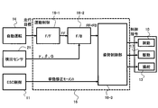
- FIG. 1 is a block diagram showing one aspect of a vehicle motion control system.
- the vehicle 100 is a four-wheeled vehicle having a left front wheel 1, a right front wheel 2, a left rear wheel 3, and a right rear wheel 4, and each wheel 1-4 has a wheel cylinder 5-8 constituting a hydraulic braking device. Equipped.
- the brake operating member 9A represented by the brake pedal transmits the braking operating force of the driver of the vehicle 100 to the master cylinder 9B, and the master cylinder 9B converts the braking operating force of the driver into hydraulic pressure.
- the braking force generating device 10 is a device that supplies hydraulic pressure to each wheel cylinder 5-8, and is a device that can adjust the braking force applied to each wheel 1-4.
- the wheel cylinder hydraulic pressure control device 11 is a device typified by a skid control device such as an ESC (Electronic Stability Control).
- a skid control device such as an ESC (Electronic Stability Control).
- the wheel cylinder hydraulic pressure control device 11 detects a skid state based on a physical quantity such as yaw rate that represents the magnitude of the turning behavior of the vehicle 100, the wheel cylinder hydraulic pressure control device 11 automatically adjusts the hydraulic pressure of each wheel cylinder 5-8 to obtain the vehicle 100.
- the posture is controlled to stabilize the turning posture of the vehicle 100.
- the braking device of the vehicle 100 is not limited to the hydraulic friction brake, and may be, for example, an electric friction brake.
- the engine torque operating member 12A represented by the accelerator pedal generates a torque command of the engine (internal combustion engine) 12B according to the operation of the driver.
- the engine control device 17 controls the torque generated by the engine 12B, that is, the driving force of the vehicle 100, in response to the torque command by the engine torque operating member 12A.
- the drive source of the vehicle 100 is not limited to the engine (internal combustion engine), and may be a motor or a combination of the engine and the motor.
- the steering device 13 is a device capable of automatic steering represented by an electric power steering device including a motor that generates steering force.
- the vehicle motion control system includes an automatic driving control device 14, a communication gateway device 15, and a vehicle integrated motion control device 16.
- the automatic driving control device 14 calculates information on a traveling target including a target trajectory and a target speed based on external world information acquired from an external world recognition sensor (not shown) such as a camera.
- the vehicle integrated motion control device 16 acquires information on the traveling target from the automatic driving control device 14, and also acquires information on the actual motion state of the vehicle 100 from the vehicle motion state detection sensor described later. Then, the vehicle integrated motion control device 16 obtains a control command for the amount of operation related to braking, driving and steering, and issues the obtained control command to the braking force generating device 10 and engine control which are actuators related to braking, driving and steering. It is a control unit that outputs to the device 17 and the steering device 13, respectively. That is, the control unit has a function of performing an operation based on the input information and outputting the calculated result.
- FIG. 2 is a functional block diagram showing one aspect of the vehicle integrated motion control device 16.
- the vehicle integrated motion control device 16 is an electronic control device including a microcomputer having a CPU, ROM, RAM, and the like.
- the vehicle integrated motion control device 16 outputs a control command to each of the braking force generating device 10 which is a braking actuator unit, the engine control device 17 which is a drive actuator unit, and the steering device 13 which is a steering actuator unit, and the vehicle 100 It is a vehicle motion control device that controls the motion of the vehicle.
- the vehicle integrated motion control device 16 acquires information on a traveling target including a target trajectory and a target speed from the automatic driving control device 14, and also acquires information on the actual motion state from the vehicle motion state detection sensor 21. , The movement of the vehicle 100 is controlled so that the vehicle 100 follows the traveling target.
- the vehicle motion state detection sensor 21 detects actual motion states such as yaw rate ⁇ , vehicle body slip angle ⁇ , and lateral acceleration G, and outputs these information to the vehicle integrated motion control device 16. Further, the vehicle integrated motion control device 16 acquires information on the behavior correction moment for suppressing the unstable behavior of the vehicle 100 such as skidding from the wheel cylinder hydraulic pressure control device 11.
- the vehicle integrated motion control device 16 includes an FF operation amount calculation unit 16-1, an FB operation amount calculation unit 16-2, and an attitude control unit 16-3.
- the FF operation amount calculation unit 16-1 is a feed forward operation amount that causes the vehicle 100 to follow the travel target based on a vehicle norm model that models the motion state of the vehicle traveling according to the travel target by the equation of motion. (First control amount) is calculated.
- the vehicle norm model is a dynamic vehicle model in which the output of the system depends not only on the input at that time but also on the internal state when the past input or phenomenon starts.
- the FB operation amount calculation unit 16-2 includes the actual motion state quantity such as the yaw rate ⁇ , the vehicle body slip angle ⁇ , and the lateral acceleration G acquired from the vehicle motion state detection sensor 21, and the target motion state quantity which is the solution of the vehicle norm model. Based on the deviation of, the feedback operation amount for mitigating the influence of disturbance and realizing the vehicle 100 to follow the traveling target is calculated.
- the motion manipulated variable MOA (second controlled variable) is represented by, for example, a force (force Fx, force Fy, moment M) in the vehicle coordinate system.
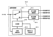
- FIG. 3 is a functional block diagram showing one aspect of the attitude control unit 16-3.
- the attitude control unit 16-3 includes a target z-axis attitude calculation unit 16-4, a linear model z-axis attitude calculation unit 16-5, a comparison unit 16-6, a switching unit 16-7, and a first attitude control unit 16-8. It has a second attitude control unit 16-9.
- the target z-axis attitude calculation unit 16-4 calculates the target z-axis attitude value, which is a physical quantity related to the target vehicle attitude based on the target trajectory, and the linear model z-axis attitude calculation unit 16-5 is linear based on the linear model of the vehicle.
- the linear model z-axis attitude value which is a physical quantity related to the model vehicle attitude, is calculated.
- the z-axis posture of the vehicle 100 is a rotational posture around the z-axis which is the vertical axis of the vehicle 100, in other words, a posture in the yaw direction of the vehicle 100, and the final target is a vehicle body sliding angle ⁇ .
- the z-axis posture command is not limited to the direct command at the vehicle body sliding angle ⁇ , and the command is given by changing only the moment M or by changing only Fy as the feedforward operation. and so on.
- the vehicle body sliding angle ⁇ which is a posture value in the yaw direction, is an angle formed by the traveling direction of the vehicle 100 and the vehicle reference line that passes through the center of gravity of the vehicle 100 and extends in the front-rear direction of the vehicle 100.
- the comparison unit 16-6 compares the target z-axis attitude value with the linear model z-axis attitude value
- the switching unit 16-7 compares the target z-axis attitude value with the first attitude control unit 16-8 based on the comparison result by the comparison unit 16-6.
- the second attitude control unit 16-9 are operated to control the z-axis attitude of the vehicle 100.
- the first attitude control unit 16-8 outputs the braking and steering operation amounts to control the z-axis attitude of the vehicle 100
- the second attitude control unit 16-9 outputs the braking and driving force operation amounts. Controls the z-axis attitude of the vehicle 100.
- the first attitude control unit 16-8, the second attitude control unit 16-9, and the wheel cylinder hydraulic pressure control device 11 all perform control to give a yaw moment to the vehicle 100.
- the second attitude control unit 16-9 gives a yaw moment to the vehicle 100 by controlling braking and driving
- the first attitude control unit 16-8 gives a yaw moment to the vehicle 100 by controlling braking and steering.
- the wheel cylinder hydraulic pressure control device 11 applies a yaw moment to the vehicle 100 by controlling braking.
- the switching unit 16-7 uses the second attitude control unit 16-9 (braking and driving control command). ) Is performed, and when the absolute value of the difference is smaller than the threshold value, the z-axis attitude control is performed by the first attitude control unit 16-8 (braking and steering control command). That is, the attitude control unit 16-3 performs attitude control by changing the distribution of the operation amount related to braking, driving, and steering based on the comparison between the target z-axis attitude value and the linear model z-axis attitude value.
- the attitude control unit 16-3 performs z-axis attitude control by braking and steering operations and z-axis attitude control by braking and driving operations based on the comparison between the target z-axis attitude value and the linear model z-axis attitude value.
- the configuration is not limited to one of the above.
- the attitude control unit 16-3 switches between the z-axis attitude control by braking and steering operation and the z-axis attitude control by braking and driving operation
- the attitude control unit 16-3 operates the z-axis attitude by braking, driving and steering operation.
- the control can be performed transiently, and the amount of braking, driving, and steering operations can be gradually changed from before switching to the command value after switching.
- the pattern for selecting the operation target from the three of braking, driving and steering in the attitude control unit 16-3 is not limited to the combination of braking and steering and the combination of braking and driving.
- the attitude control unit 16-3 can include a pattern in which one of braking, driving, and steering is selected as an operation target, and a pattern in which all of braking, driving, and steering are operation targets. Then, the attitude control unit 16-3 can select a control target from three or more patterns based on the comparison between the target z-axis attitude value and the linear model z-axis attitude value.
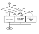
- FIG. 4 shows the target z-axis attitude calculation unit 16-4, the linear model z-axis attitude calculation unit 16-5, the comparison unit 16-6, and the switching unit 16-7 among the control functions of the attitude control unit 16-3. It is a flowchart which shows one aspect of the processing content of.
- Attitude control unit 16-3 first calculates the target z-axis attitude value ZPOG (requested z-axis attitude value) in step S1001.
- the target z-axis attitude value ZPOG is a required value of the vehicle z-axis attitude for the vehicle 100 to follow the target trajectory
- the attitude control unit 16-3 target z-axis attitude calculation unit 16-4
- the attitude control unit 16-3 calculates the linear model z-axis attitude value ZPLM (reference z-axis attitude value) in step S1002.
- the linear model z-axis attitude value ZPLM is the vehicle z-axis attitude based on the linear model of the vehicle 100
- the attitude control unit 16-3 (linear model z-axis attitude calculation unit 16-5) is the vehicle specifications.
- the operating conditions of the vehicle 100 such as the vehicle speed, turning radius, steering angle, and target lateral force are input to the linear model of the vehicle 100 to obtain the linear model z-axis attitude value ZPLM.
- the attitude control unit 16-3 uses the target z-axis attitude value ZPOG, which is the target value of the vehicle z-axis attitude, and the vehicle z-axis attitude obtained based on the linear model of the vehicle 100 in step S1003 (comparison unit 16-6). Compare with a linear model z-axis attitude value ZPLM. In step S1003, the attitude control unit 16-3 determines whether or not the target z-axis attitude value ZPOG is within a predetermined range (neighborhood region) centered on the linear model z-axis attitude value ZPLM.
- the attitude control unit 16-3 is in a state where the absolute value of the deviation between the target z-axis attitude value ZPOG and the linear model z-axis attitude value ZPLM matches the threshold value ⁇ ZP ( ⁇ ZP> 0) or is smaller than the threshold value ⁇ ZP (
- the attitude control unit 16-3 (switching unit 16-7) proceeds to step S2000 and first The z-axis attitude of the vehicle 100 is controlled by controlling braking and steering by the attitude control unit 16-8.
- the attitude control unit 16-3 switching unit 16-7) , 1st attitude control unit 16-8, 2nd attitude control unit 16-9 to 1st attitude control unit 16-8, that is, z-axis attitude control by braking and steering is selected.
- the attitude control unit 16-3 (switching unit 16-7) proceeds to step S3000 and proceeds to step S3000. 2
- the z-axis attitude of the vehicle 100 is controlled by controlling braking and driving by the attitude control unit 16-9.
- the attitude control unit 16-3 switching unit 16-7
- the first attitude control unit 16-8, the second attitude control unit 16-9 to the second attitude control unit 16-9, that is, the z-axis attitude control by braking and driving is selected.
- the attitude control unit 16-3 (switching unit 16-7) controls braking and driving when the deviation between the target z-axis attitude value ZPOG and the linear model z-axis attitude value ZPLM is larger than the determination value. 2
- the tire nonlinearity in the region where the running requirement can be satisfied. It will be expanded toward the area so that the driving requirements can be met to the maximum (see FIG. 5).
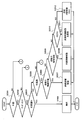
- FIG. 6 is a flowchart showing a procedure for controlling braking and driving by the second attitude control unit 16-9.
- the second attitude control unit 16-9 follows the procedure shown in the flowchart of FIG. 6 when the deviation between the target z-axis attitude value ZPOG and the linear model z-axis attitude value ZPLM is larger than the determination value. Control braking and driving.
- the second attitude control unit 16-9 determines whether or not the target z-axis attitude value ZPOG is larger than the linear model z-axis attitude value ZPLM.
- a state in which the target z-axis attitude value ZPOG is larger than the linear model z-axis attitude value ZPLM is a state in which there is a request to increase the vehicle body sliding angle ⁇ , in other words, there is a request to turn the vehicle 100 more inward. Such a requirement indicates that the turning behavior of the vehicle 100 tends to be understeer.
- a state in which the target z-axis attitude value ZPOG is smaller than the linear model z-axis attitude value ZPLM is a state in which there is a request for the vehicle body sliding angle ⁇ to be smaller, in other words, there is a request for the vehicle 100 to be turned more outward.
- the requirement indicates that the turning behavior of the vehicle 100 tends to oversteer (turn outward).
- the second attitude control unit 16-9 proceeds to step S3002 and proceeds to step S3002, and the vehicle body sliding angle ⁇ of the actual vehicle. It is determined whether or not the detected value or the estimated value (hereinafter referred to as the actual vehicle body sliding angle ⁇ ) exceeds the threshold value ⁇ TH (predetermined angle). Then, when the actual vehicle body sliding angle ⁇ exceeds the threshold value ⁇ TH, the second attitude control unit 16-9 proceeds to step S3003 and determines whether or not the vehicle 100 is accelerating.
- the threshold value ⁇ TH predetermined angle
- step S3004. When the behavior of the vehicle 100 tends to be understeer, the actual vehicle body sliding angle ⁇ exceeds the threshold value ⁇ TH, and the vehicle 100 is accelerating, the second attitude control unit 16-9 moves to step S3004. move on.
- step S3004 the second attitude control unit 16-9 gives a yaw moment that directs the vehicle 100 toward the inside of the turn by mainly controlling the drive, promotes the rotation of the vehicle 100 around the z-axis, and causes an understeer tendency. Suppress.
- the second attitude control unit 16-9 increases the driving force (engine output torque) in step S3004 to bring the vehicle into a so-called drift driving state, and sets the target turning locus. Turn the vehicle 100 inward and reduce the driving force when it turns to neutral steer or oversteer tendency.
- the second attitude control unit 16-9 reduces the driving force (engine output torque) to induce so-called tuck-in in step S3004, and inside the target turning locus. The vehicle 100 is turned toward the vehicle 100, and when the tendency toward neutral steer or oversteer is changed, the driving force is returned.
- the second attitude control unit 16-9 gives a yaw moment to the vehicle 100 by controlling the drive when the actual vehicle body sliding angle ⁇ exceeds the threshold value ⁇ TH. That is, the threshold value ⁇ TH is a value adapted so that it can be distinguished whether or not the yaw moment can be applied to the vehicle 100 by controlling the drive.
- the second attitude control unit 16-9 can additionally apply a yaw moment to the vehicle 100 by braking force control in the rotation promotion process mainly for drive control in step S3004, and the drive in step S3008 described later. The same applies to rotation suppression by control.
- step S3005 the second attitude control unit 16-9 performs braking force distribution control that applies braking force to the wheels inside the turn to give a yaw moment to the vehicle 100, and rotates the vehicle 100 around the z-axis.
- the second attitude control unit 16-9 reduces the yaw moment due to braking, and then controls the drive if it is in an accelerated state to recover the vehicle speed. And so on.
- the second attitude control unit 16-9 performs braking force distribution control that applies braking force to the wheels inside the turn to give a yaw moment to the vehicle 100, and the vehicle 100 accelerates with the attitude control. While suppressing it, the rotation around the z-axis is promoted, and when the behavior of the vehicle 100 changes to a neutral steer or oversteer tendency, the yaw moment given by braking is reduced.
- step S3006 the second attitude control unit 16-9 determines whether or not the detected value of the actual vehicle body slip angle ⁇ exceeds the threshold value ⁇ TH (predetermined angle). Then, when the actual vehicle body sliding angle ⁇ exceeds the threshold value ⁇ TH, the second attitude control unit 16-9 proceeds to step S3007 and determines whether or not the vehicle 100 is accelerating.
- the second attitude control unit 16-9 performs step S3008.
- the drive engine output torque
- the rotation of the vehicle 100 around the z-axis is suppressed.
- the second attitude control unit 16-9 gives a yaw moment that suppresses the rotation of the vehicle 100 by reducing the driving force, and drives the vehicle 100 when the behavior changes to neutral steer or understeer. Regain power.
- the second attitude control unit 16-9 performs step S3009. Proceeding to, the rotation of the vehicle 100 around the z-axis is suppressed and suppressed mainly by controlling the braking.
- the second attitude control unit 16-9 executes braking force distribution control that applies braking force to the wheels on the outer side of turning to generate a yaw moment that suppresses rotation of the vehicle 100 around the z-axis, and the vehicle 100.
- the behavior of is changed to neutral steer or understeer tendency, the yaw moment in the rotation restraint direction due to braking force distribution is reduced.
- the second attitude control unit 16-9 bypasses step S3007 and steps. Proceeding to S3008, the rotation of the vehicle 100 around the z-axis is suppressed mainly by controlling the drive (engine output torque).
- the second attitude control unit 16-9 bypasses step S3006 to step S3007 and proceeds to step S3008, if the vehicle 100 is accelerating, the driving force is increased to intentionally push under the state. As a result, the rotation of the vehicle 100 around the z-axis is suppressed, and the driving force is reduced when the vehicle 100 tends to understeer.
- the second attitude control unit 16-9 reduces the driving force to zero when the vehicle 100 is decelerating or coasting instead of accelerating when the vehicle 100 bypasses step S3006 and proceeds to step S3008.
- the rotation of the vehicle 100 around the z-axis is suppressed by reducing the driving force such as.
- the second attitude control unit 16-9 controls the turning behavior by controlling braking and driving so as to return to the linear behavior. It is possible to improve the followability to the traveling target (target trajectory) (see FIG. 7). Further, in the braking and driving control by the second attitude control unit 16-9, it is not evaluated whether or not the running requirement can be satisfied, so that it is possible to suppress the deterioration of the followability to the running target due to the response delay of the motion control. it can.
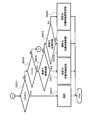
- step S2001 the first attitude control unit 16-8 determines whether the position of the own vehicle is outside or inside the target turning locus.
- the first attitude control unit 16-8 proceeds to step S2002 and determines whether or not the own vehicle behavior tends to understeer.
- the first attitude control unit 16-8 proceeds to step S2003 and determines whether or not there is a response delay in steering control.
- the response delay of the steering control is the delay in following the actual steering angle to the target steering angle
- the first attitude control unit 16-8 is, for example, when the actual steering angle follows the change in the target steering angle. It is possible to determine the presence or absence of a response delay in steering control based on a constant or the like. For example, the first attitude control unit 16-8 determines that there is a response delay in steering control when the time constant when the actual steering angle follows the change in the target steering angle is larger than the determination value.
- the first attitude control unit 16-8 proceeds to step S2004, and the steering control suppresses the tendency of understeer toward the traveling direction of the vehicle 100 toward the inside of the turn. Since there is a tendency of understeer due to the response delay of the steering control, the first attitude control unit 16-8 increases the control amount of the steering device 13 to promote the increase of the steering angle ⁇ in step S2004.
- the first attitude control unit 16-8 determines in step S2003 that the response delay of the steering control is sufficiently small, the first attitude control unit 16-8 proceeds to step S2005 and the vehicle speed is higher than the predetermined speed (medium speed) or the predetermined speed (medium speed). It is determined whether or not the vehicle 100 is fast, in other words, whether or not the vehicle 100 is traveling at a medium or high speed.
- the vehicle speed is a predetermined speed or faster than the predetermined speed and the vehicle 100 is traveling at a medium or high speed
- the first attitude control unit 16-8 proceeds to step S2006, and the yaw moment required to suppress the understeer tendency is the rear wheel. Judge whether or not the yaw moment can be generated by distributing the braking force to.
- the first attitude control unit 16-8 obtains the required yaw moment from the behavior correction moment, the feedforward operation amount, the feedback operation amount, and the like.
- the first attitude control unit 16-8 proceeds to step S2007 to apply the braking force to the rear wheels inside the turn. Generates a yaw moment that suppresses the tendency to understeer. If the vehicle speed is medium or high speed, it is difficult to give a feeling of braking even if a braking force is applied to generate a yaw moment. Therefore, the first attitude control unit 16-8 mainly controls braking in step S2007. As a result, a yaw moment is generated to suppress the tendency of understeer.
- the first attitude control unit 16-8 proceeds to step S2008 and generates the required yaw moment by distributing the braking force to the front wheels. Determine if it can be done. Then, when the required yaw moment can be generated by distributing the braking force to the front wheels, the first attitude control unit 16-8 proceeds to step S2009 and applies braking force to the rear wheels and the front wheels inside the turn. , Generates a yaw moment in the direction of suppressing the tendency of understeer.
- the first attitude control unit 16-8 proceeds to step S2010 and adds a margin to the maximum lateral force that can be generated by steering.
- the threshold value ⁇ m which is the steering angle equivalent to the lateral force, is compared with the steering angle ⁇ of the actual vehicle (hereinafter referred to as the actual steering angle ⁇ ), and it is determined whether the actual steering angle ⁇ matches the threshold value ⁇ m or is smaller than the threshold value ⁇ m. To do. That is, it is estimated that the first attitude control unit 16-8 can give a yaw moment for suppressing the understeer tendency by steering control when the actual steering angle ⁇ matches the threshold value ⁇ m or is smaller than the threshold value ⁇ m. .. On the other hand, the first attitude control unit 16-8 estimates that when the actual steering angle ⁇ exceeds the threshold value ⁇ m, the steering control cannot sufficiently give the yaw moment for suppressing the tendency of understeer.
- step S2011 the first attitude control unit 16-8 applies braking force to the rear wheels and front wheels on the inside of the turn, further increases the actual steering angle ⁇ , and directs the traveling direction of the vehicle 100 to the inside of the turn. Gives a moment and suppresses the tendency of understeer.
- the first attitude control unit 16-8 has step S2012. Proceed to. In step S2012, the first attitude control unit 16-8 increases the actual steering angle ⁇ , applies braking force to the four wheels to decelerate, and further, the wheel cylinder hydraulic pressure control device 11 (sideslip prevention device). The hydraulic pressure of the wheel cylinder 5-8 is adjusted based on the behavior correction moment from. The first attitude control unit 16-8 can shift to braking and drive control by the second attitude control unit 16-9 in step S2012.
- step S2005 determines in step S2005 that the vehicle speed is in a low speed state lower than the predetermined speed
- the first attitude control unit 16-8 proceeds to step S2013 (see FIG. 9).
- step S2013 the first attitude control unit 16-8 determines whether the actual steering angle ⁇ matches the threshold value ⁇ ma corresponding to the maximum lateral force that can be generated by steering or is smaller than the threshold value ⁇ ma.
- the first attitude control unit 16-8 When the actual steering angle ⁇ matches the threshold value ⁇ ma or is smaller than the threshold value ⁇ ma, the first attitude control unit 16-8 is in a state where the yaw moment for suppressing the understeer tendency can be generated by steering control. The determination is made, and the process proceeds to step S2014.
- the first attitude control unit 16-8 increases the actual steering angle ⁇ to give a yaw moment that directs the traveling direction of the vehicle 100 toward the inside of the turn, and suppresses the understeer tendency of the vehicle behavior.
- the first attitude control unit 16-8 proceeds to step S2015 and determines whether or not the actual steering angle ⁇ is smaller than the threshold value ⁇ m ( ⁇ m> ⁇ ma).
- the first attitude control unit 16-8 proceeds to step S2016, and the yaw moment required for suppressing the tendency of understeer can be generated by distributing the braking force to the rear wheels. Determine if it is a yaw moment.
- the first attitude control unit 16-8 proceeds to step S2017 to increase the actual steering angle ⁇ .
- a braking force is applied to the rear wheels on the inside of the turn to give a yaw moment in the direction of suppressing the tendency of understeer.
- step S2016 determines in step S2016 that the yaw moment required to suppress the understeer tendency is larger than the yaw moment that can be generated by distributing the braking force to the rear wheels
- step S2018 determines in step S2018. move on.
- step S2018 the first attitude control unit 16-8 determines whether or not the yaw moment required for suppressing the understeer tendency can be generated by distributing the braking force to the front wheels.
- the first attitude control unit 16-8 proceeds to step S2019 to increase the actual steering angle ⁇ and turn inside. Braking force is applied to the rear wheels and front wheels to give a yaw moment in the direction of suppressing the tendency of understeer.
- the first attitude control unit 16-8 proceeds to step S2020 to control the rear wheels and front wheels inside the turn. After increasing the power to a predetermined limit value, the actual steering angle ⁇ is increased to a predetermined limit value to suppress the tendency of understeer. Further, when the first attitude control unit 16-8 determines in step S2015 that the actual steering angle ⁇ matches the threshold value ⁇ m or is larger than the threshold value ⁇ m, the first attitude control unit 16-8 proceeds to step S2021 (see FIG. 10) to suppress the tendency of understeer.
- the first attitude control unit 16-8 proceeds to step S2022 and the actual steering angle ⁇ is set.
- the predetermined limit value is reached, the shortage of the yaw moment is generated by applying a braking force to the rear wheels inside the turn.
- the first attitude control unit 16-8 proceeds to step S2023 to suppress the understeer tendency. It is determined whether or not the yaw moment required for the above can be generated by distributing the braking force to the front wheels. Then, when the yaw moment required for suppressing the tendency to understeer can be generated by distributing the braking force to the front wheels, the first attitude control unit 16-8 proceeds to step S2024, and the actual steering angle ⁇ is a predetermined limit value. The shortage of yaw moment is generated by applying braking force to the rear wheels and front wheels on the inside of the turn.
- the first attitude control unit 16-8 proceeds from step S2023 to step S2025, and the actual steering angle ⁇ is predetermined.
- the limit value is reached, braking force is applied to the four wheels to decelerate, and the liquid in the wheel cylinder 5-8 based on the behavior correction moment from the wheel cylinder hydraulic pressure control device 11 (sideslip prevention device). Have the pressure adjusted.
- the first attitude control unit 16-8 can shift to the vehicle z-axis attitude control (braking and drive control) by the second attitude control unit 16-9 in step S2025.
- step S2002 determines in step S2002 that the vehicle behavior is not an understeer tendency but an oversteer tendency
- the process proceeds to step S2026 (see FIG. 11), and there is a response delay in steering control. Judge whether or not.
- the first attitude control unit 16-8 proceeds to step S2027 and executes steering control (counter steer) for steering in the direction opposite to the traveling direction to suppress the tendency of oversteer. .. Since there is a delay in the response of the steering control, the first attitude control unit 16-8 increases the control amount of the steering device 13 in step S2027 to promote the return of the steering angle ⁇ .
- the first attitude control unit 16-8 proceeds to step S2028 and applies the yaw moment required to suppress the oversteer tendency outside the target locus to the front wheels. Judge whether or not it can be generated by braking force distribution.
- the first attitude control unit 16-8 proceeds to step S2029 and applies the braking force to the front wheels on the outer side of the turn to oversteer the tendency. Gives a yaw moment that suppresses.
- the first attitude control unit 16-8 proceeds to step S2032 and behaves from the wheel cylinder hydraulic pressure control device 11 (sideslip prevention device).
- the hydraulic pressure of the wheel cylinder 5-8 is adjusted based on the correction moment, or the vehicle z-axis attitude control (braking and drive control) is performed by the second attitude control unit 16-9.
- the above processing is the processing when the first attitude control unit 16-8 determines in step S2001 that the position of the own vehicle is outside the target turning locus.
- step S2001 When the first attitude control unit 16-8 determines in step S2001 that the position of the own vehicle is inside the target turning locus, the first attitude control unit 16-8 proceeds to step S2033 (see FIG. 12). In step S2033, the first attitude control unit 16-8 determines whether or not the turning behavior of the vehicle 100 tends to be understeer. Then, when the vehicle behavior tends to be understeer, the first attitude control unit 16-8 proceeds to step S2034 and suppresses the understeer tendency by steering control that increases the actual steering angle ⁇ .
- the first attitude control unit 16-8 proceeds to step S2035, and the response delay of the steering control is delayed. Determine if it exists. Then, when there is a response delay in the steering control, the first attitude control unit 16-8 proceeds to step S2036, performs counter steer as steering control, and suppresses the tendency of oversteer. Since there is a delay in the response of the steering control, the first attitude control unit 16-8 increases the control amount of the steering device 13 in step S2036 to promote the return of the actual steering angle ⁇ .
- the first attitude control unit 16-8 proceeds from step S2035 to step S2037 and is in a medium-high speed state in which the vehicle speed is a predetermined speed (medium speed) or faster than the predetermined speed. Judge whether or not.
- the vehicle speed is medium or high speed
- the first attitude control unit 16-8 proceeds to step S2038 and determines whether or not the friction coefficient ⁇ of the road surface on which the vehicle 100 is traveling is a predetermined value or smaller than a predetermined value, that is, the vehicle. It is determined whether or not 100 is traveling on a slippery road surface such as a wet road surface or a snowy road.
- the first attitude control unit 16-8 estimates the information of the coefficient of friction ⁇ of the road surface from the running state such as the slip of the wheels 1-4, and transmits the in-vehicle network from other electronic control devices mounted on the vehicle 100. It can be acquired via wireless communication or can be acquired from an external device of the vehicle 100.
- the first attitude control unit 16-8 determines whether or not the actual steering angle ⁇ is smaller than the angle ⁇ th obtained by adding the predetermined angle ⁇ to the actual vehicle body sliding angle ⁇ . When the actual steering angle ⁇ is smaller than the angle ⁇ th, the first attitude control unit 16-8 proceeds to step S2040 and performs countersteering with the angle ⁇ th as the limit as steering control to suppress the tendency of oversteer.
- the first attitude control unit 16-8 proceeds to step S2041 and obtains the yaw moment required to suppress the oversteer tendency inside the target locus. Determine whether or not it can be generated by distributing the braking force to the front wheels.
- the first attitude control unit 16-8 proceeds to step S2042, in a state where the countersteer reaches the limit angle ⁇ th. , Braking control that applies braking force to the front wheels on the outside of turning is performed to suppress the tendency of oversteer.
- the first attitude control unit 16-8 proceeds to step S2043, and the countersteer reaches the limit angle ⁇ th. Braking control is performed to apply braking force above the limit to the front wheels on the outside of turning to suppress the tendency of oversteer.
- the first attitude control unit 16-8 determines whether or not the yaw moment required to suppress the oversteer tendency inside the target locus can be given by the braking force distribution to the front wheels. ..
- the first attitude control unit 16-8 proceeds to step S2045, performs braking control for applying the braking force to the front wheels on the outer side of the turn, and over. Suppress the tendency to steer.
- the vehicle speed is medium and high speed, in order to avoid inducing unstable behavior due to the return delay of the steering angle ⁇ and the error after counter-steering as much as possible
- Counter steer is not performed by controlling the steering angle ⁇ for turning.
- step S2046 the first attitude control unit 16-8 determines whether or not the actual steering angle ⁇ is smaller than the angle ⁇ th obtained by adding the predetermined angle ⁇ to the vehicle body sliding angle ⁇ . Then, when the actual steering angle ⁇ is smaller than the angle ⁇ th, the first attitude control unit 16-8 proceeds to step S2047, applies a braking force to the front wheels on the outer side of the turn, and can generate a yaw moment by the braking control. If it is insufficient to suppress the oversteer tendency, countersteer with the angle ⁇ th as the limit is performed to suppress the oversteer tendency.
- the first attitude control unit 16-8 proceeds to step S2048, performs counter-steering with the angle ⁇ th as the limit, and applies braking force to the four wheels.
- the hydraulic pressure of the wheel cylinder 5-8 is adjusted based on the behavior correction moment from the wheel cylinder hydraulic pressure control device 11 (sideslip prevention device).
- the first attitude control unit 16-8 can shift to vehicle z-axis attitude control (braking and drive control) by the second attitude control unit 16-9 in step S2048.
- the first attitude control unit 16-8 moves from step S2037 to step S2049 (see FIG. 15). move on.
- step S2049 the first attitude control unit 16-8 determines whether or not the actual steering angle ⁇ is smaller than the angle ⁇ th obtained by adding the predetermined angle ⁇ to the vehicle body sliding angle ⁇ . Then, when the actual steering angle ⁇ is smaller than the angle ⁇ th, the first attitude control unit 16-8 proceeds to step S2050 and performs countersteering with the angle ⁇ th as the limit to suppress the oversteer tendency.
- the first attitude control unit 16-8 proceeds to step S2051 and obtains the yaw moment required to suppress the oversteer tendency inside the target locus. Determine whether or not it can be generated by distributing the braking force to the front wheels.
- the first attitude control unit 16-8 proceeds to step S2052, performs countersteering with the angle ⁇ th as the limit, and turns outside. Braking control that applies braking force to the front wheels of the vehicle is performed to suppress the tendency of oversteer.
- the first attitude control unit 16-8 proceeds to step S2053, performs countersteering with the angle ⁇ th as the limit, and four wheels. Is decelerated by applying a braking force to the wheel cylinder, and further, the hydraulic pressure of the wheel cylinder 5-8 is adjusted based on the behavior correction moment from the wheel cylinder hydraulic pressure control device 11 (sideslip prevention device).
- the first attitude control unit 16-8 can shift to the vehicle z-axis attitude control (braking and drive control) by the second attitude control unit 16-9 in step S2053.
- the comparison unit 16-6 sets a threshold value ⁇ ZP to be compared with the absolute value of the deviation between the target z-axis attitude value ZPOG and the linear model z-axis attitude value ZPLM according to the friction coefficient of the road surface, the gradient, the vehicle speed condition, and the like. It can be set variably. That is, the selection conditions of the first attitude control unit 16-8 and the second attitude control unit 16-9 are not limited to the deviation between the target z-axis attitude value ZPOG and the linear model z-axis attitude value ZPLM, and are added to the deviation. Therefore, road surface conditions and running conditions can be used as selection conditions.
- the attitude control unit 16-3 can notify the driver of the vehicle 100 by a lamp or the like that the attitude control is being performed by the second attitude control unit 16-9. Further, in the braking and driving control by the second attitude control unit 16-9 shown in the flowchart of FIG. 6, either braking or driving is mainly controlled according to the conditions, but braking and driving are performed in parallel. It is possible to control the attitude.
- the present invention is not limited to the above-described embodiment, and includes various modifications.
- the above-described embodiment has been described in detail in order to explain the present invention in an easy-to-understand manner, and is not necessarily limited to the one including all the described configurations.
- it is possible to replace a part of the configuration of one embodiment with the configuration of another embodiment and it is also possible to add the configuration of another embodiment to the configuration of one embodiment.
Landscapes
- Engineering & Computer Science (AREA)
- Transportation (AREA)
- Mechanical Engineering (AREA)
- Automation & Control Theory (AREA)
- Chemical & Material Sciences (AREA)
- Combustion & Propulsion (AREA)
- Physics & Mathematics (AREA)
- Mathematical Physics (AREA)
- Human Computer Interaction (AREA)
- Regulating Braking Force (AREA)
- Control Of Driving Devices And Active Controlling Of Vehicle (AREA)
- Steering Control In Accordance With Driving Conditions (AREA)
Abstract
本発明に係る運動制御においては、目標軌跡に基づく目標車両姿勢に関する物理量と車両の線形モデルに基づく線形モデル車両姿勢に関する物理量との差が閾値を超えるときは、制動および駆動に関する操作量を制御指令とし、前記差が前記閾値に一致するか又は前記閾値より小さいときは、制動および操舵に関する操作量を制御指令とし、制御指令に基づき車両のヨー方向の姿勢を制御する。
Description
本発明は、目標軌跡を含む走行目標に応じて車両の運動を制御する、車両運動制御装置、車両運動制御方法、及び車両運動制御システムに関する。
特許文献1には、目標軌跡や速度パターン等の走行目標に応じて走行する車両の運動状態をモデル化した動的車両モデルに基づいて、実車両の操作に必要な操作量を変化させる操作量と運動状態量を算出するとともに、算出された操作量と運動状態量が実車両に対する所定の走行要求を満たせるか否かを判断し、前記走行要求を満たせると判断された操作量と運動状態量のそれぞれを、フィードフォワード操作量と状態フィードバック制御における目標状態量として設定する、車両用制御装置が開示されている。
特許文献1のように、算出した操作量と運動状態量が実車両に対する所定の走行要求を満たせるか否かを判断する場合、判断精度の不足や、走行要求を満たせないと判断した場合に解を見つけるまでの時間、解が無いことが分かるまでの時間などによる応答遅れによって、走行目標への追従性が悪化するおそれがあった。
本発明の目的は、走行目標に対する実車両の追従性を向上させることができる、車両運動制御装置、車両運動制御方法、及び車両運動制御システムを提供することにある。
本発明の一実施形態によると、目標軌跡を含む走行目標に応じて走行するための車両の運動状態をモデル化した車両運動モデルに基づいて、前記車両の操作に必要な操作量である第1制御量を求め、前記第1制御量と、前記車両の実運動状態を検出する車両運動状態検出センサから入力された前記実運動状態と、に基づき前記車両の操作量である第2制御量を求め、前記第2制御量と、前記目標軌跡に基づく目標車両姿勢に関する物理量と、前記車両の線形モデルに基づく線形モデル車両姿勢に関する物理量と、に基づき前記車両の制動、駆動および操舵に関わる操作量の制御指令を求める。
本発明の一実施形態によれば、走行目標に対する実車両の追従性を向上させることができる。
以下、本発明に係る車両運動制御装置、車両運動制御方法、及び車両運動制御システムの実施形態を、図面に基づいて説明する。
図1は、車両運動制御システムの一態様を示すブロック図である。
車両100は、左前輪1,右前輪2,左後輪3,右後輪4を有した4輪車両であり、各車輪1-4は、液圧式制動装置を構成するホイルシリンダ5-8を具備する。
図1は、車両運動制御システムの一態様を示すブロック図である。
車両100は、左前輪1,右前輪2,左後輪3,右後輪4を有した4輪車両であり、各車輪1-4は、液圧式制動装置を構成するホイルシリンダ5-8を具備する。
ブレーキペダルに代表されるブレーキ操作部材9Aは、車両100の運転者の制動操作力をマスタシリンダ9Bに伝え、マスタシリンダ9Bは、運転者の制動操作力を液圧に変換する。
制動力発生装置10は、各ホイルシリンダ5-8に液圧を供給する装置であって、各車輪1-4に与える制動力を調整可能な装置である。
制動力発生装置10は、各ホイルシリンダ5-8に液圧を供給する装置であって、各車輪1-4に与える制動力を調整可能な装置である。
また、ホイルシリンダ液圧制御装置11は、ESC(Electronic Stability Control)などの横滑り制御装置に代表される装置である。
ホイルシリンダ液圧制御装置11は、例えば、ヨーレートなどの車両100の旋回挙動の大きさを表す物理量に基づき横滑り状態を検知すると、各ホイルシリンダ5-8の液圧を自動調整して車両100の姿勢を制御し、車両100の旋回姿勢を安定化させる。
なお、車両100の制動装置は、液圧式の摩擦ブレーキに限定されず、例えば、電動式の摩擦ブレーキとすることができる。
ホイルシリンダ液圧制御装置11は、例えば、ヨーレートなどの車両100の旋回挙動の大きさを表す物理量に基づき横滑り状態を検知すると、各ホイルシリンダ5-8の液圧を自動調整して車両100の姿勢を制御し、車両100の旋回姿勢を安定化させる。
なお、車両100の制動装置は、液圧式の摩擦ブレーキに限定されず、例えば、電動式の摩擦ブレーキとすることができる。
また、アクセルペダルに代表されるエンジントルク操作部材12Aは、運転者の操作に応じてエンジン(内燃機関)12Bのトルク指令を生成する。
エンジン制御装置17は、エンジントルク操作部材12Aによるトルク指令に応じて、エンジン12Bの発生トルク、つまり、車両100の駆動力を制御する。
エンジン制御装置17は、エンジントルク操作部材12Aによるトルク指令に応じて、エンジン12Bの発生トルク、つまり、車両100の駆動力を制御する。
なお、車両100の駆動源はエンジン(内燃機関)に限定されず、モータ若しくはエンジンとモータとの組み合わせとすることができる。
また、操舵装置13は、操舵力を発生するモータを備える電動パワーステアリング装置に代表される、自動操舵可能な装置である。
また、操舵装置13は、操舵力を発生するモータを備える電動パワーステアリング装置に代表される、自動操舵可能な装置である。
また、車両運動制御システムは、自動運転制御装置14、通信ゲートウェイ装置15、車両統合運動制御装置16を備える。
自動運転制御装置14は、カメラなどの外界認識センサ(図示省略)から取得した外界情報などに基づき、目標軌跡や目標速度などを含む走行目標に関する情報を演算する。
自動運転制御装置14は、カメラなどの外界認識センサ(図示省略)から取得した外界情報などに基づき、目標軌跡や目標速度などを含む走行目標に関する情報を演算する。
車両統合運動制御装置16は、自動運転制御装置14から走行目標に関する情報を取得し、また、後述する車両運動状態検出センサから車両100の実運動状態に関する情報を取得する。
そして、車両統合運動制御装置16は、制動、駆動および操舵に関わる操作量の制御指令を求め、求めた制御指令を、制動、駆動および操舵に関わるアクチュエータ部である制動力発生装置10、エンジン制御装置17、操舵装置13にそれぞれ出力するコントロール部である。つまり、コントロール部は入力された情報に基づいて演算を行い、演算した結果を出力する機能を備える。
そして、車両統合運動制御装置16は、制動、駆動および操舵に関わる操作量の制御指令を求め、求めた制御指令を、制動、駆動および操舵に関わるアクチュエータ部である制動力発生装置10、エンジン制御装置17、操舵装置13にそれぞれ出力するコントロール部である。つまり、コントロール部は入力された情報に基づいて演算を行い、演算した結果を出力する機能を備える。
図2は、車両統合運動制御装置16の一態様を示す機能ブロック図である。
車両統合運動制御装置16は、CPU、ROM、RAMなどを有するマイクロコンピュータを備えた電子制御装置である。
車両統合運動制御装置16は、CPU、ROM、RAMなどを有するマイクロコンピュータを備えた電子制御装置である。
また、車両統合運動制御装置16は、制動アクチュエータ部である制動力発生装置10、駆動アクチュエータ部であるエンジン制御装置17、操舵アクチュエータ部である操舵装置13それぞれに制御指令を出力して、車両100の運動を制御する車両運動制御装置である。
ここで、車両統合運動制御装置16は、目標軌跡や目標速度などを含む走行目標に関する情報を自動運転制御装置14から取得し、また、車両運動状態検出センサ21から実運動状態に関する情報を取得し、走行目標に車両100が追従するように車両100の運動を制御する。
ここで、車両統合運動制御装置16は、目標軌跡や目標速度などを含む走行目標に関する情報を自動運転制御装置14から取得し、また、車両運動状態検出センサ21から実運動状態に関する情報を取得し、走行目標に車両100が追従するように車両100の運動を制御する。
車両運動状態検出センサ21は、ヨーレートγ、車体滑り角β、横加速度Gなどの実運動状態を検出し、これらの情報を車両統合運動制御装置16に出力する。
更に、車両統合運動制御装置16は、ホイルシリンダ液圧制御装置11から、横滑りなどの車両100の不安定な挙動を抑制するための挙動修正モーメントに関する情報を取得する。
更に、車両統合運動制御装置16は、ホイルシリンダ液圧制御装置11から、横滑りなどの車両100の不安定な挙動を抑制するための挙動修正モーメントに関する情報を取得する。
車両統合運動制御装置16は、FF操作量演算部16-1、FB操作量演算部16-2、姿勢制御部16-3を有する。
FF操作量演算部16-1は、走行目標に応じて走行する車両の運動状態を運動方程式によってモデル化した車両規範モデルに基づいて、走行目標への追従を車両100に実現させるフィードフォワード操作量(第1制御量)を演算する。
なお、車両規範モデルは、システムの出力がその時刻の入力だけでなく、過去の入力や現象が始まったときの内部状態に依存する動的車両モデルである。
FF操作量演算部16-1は、走行目標に応じて走行する車両の運動状態を運動方程式によってモデル化した車両規範モデルに基づいて、走行目標への追従を車両100に実現させるフィードフォワード操作量(第1制御量)を演算する。
なお、車両規範モデルは、システムの出力がその時刻の入力だけでなく、過去の入力や現象が始まったときの内部状態に依存する動的車両モデルである。
FB操作量演算部16-2は、車両運動状態検出センサ21から取得したヨーレートγ、車体滑り角β、横加速度Gなどの実運動状態量と、車両規範モデルの解である目標運動状態量との偏差に基づき、外乱影響を緩和して走行目標への追従を車両100に実現させるフィードバック操作量を演算する。
そして、FB操作量演算部16-2は、フィードフォワード操作量(第1制御量)及びフィードバック操作量から求めた運動操作量MOA(運動操作量MOA=フィードフォワード操作量+フィードバック操作量)を、姿勢制御部16-3に出力する。
なお、運動操作量MOA(第2制御量)は、例えば、車両座標系での力(力Fx、力Fy、モーメントM)で表現される。
なお、運動操作量MOA(第2制御量)は、例えば、車両座標系での力(力Fx、力Fy、モーメントM)で表現される。
図3は、姿勢制御部16-3の一態様を示す機能ブロック図である。
姿勢制御部16-3は、目標z軸姿勢演算部16-4、線形モデルz軸姿勢演算部16-5、比較部16-6、切換え部16-7、第1姿勢制御部16-8、第2姿勢制御部16-9を有する。
姿勢制御部16-3は、目標z軸姿勢演算部16-4、線形モデルz軸姿勢演算部16-5、比較部16-6、切換え部16-7、第1姿勢制御部16-8、第2姿勢制御部16-9を有する。
目標z軸姿勢演算部16-4は、目標軌跡に基づく目標車両姿勢に関する物理量である目標z軸姿勢値を演算し、線形モデルz軸姿勢演算部16-5は、車両の線形モデルに基づく線形モデル車両姿勢に関する物理量である線形モデルz軸姿勢値を演算する。
ここで、車両100のz軸姿勢は、車両100の上下軸であるz軸周りの回転姿勢、換言すれば、車両100のヨー方向の姿勢であり、最終的な目標としては車体滑り角βとなる。
ここで、車両100のz軸姿勢は、車両100の上下軸であるz軸周りの回転姿勢、換言すれば、車両100のヨー方向の姿勢であり、最終的な目標としては車体滑り角βとなる。
但し、z軸姿勢の指令においては、車体滑り角βで直接指令することに限定されず、モーメントMのみを変化させて指令する場合や、フィードフォワード操作としてのFyのみを変化させて指令する場合などがある。
なお、ヨー方向の姿勢値である車体滑り角βは、車両100の進行方向と、車両100の重心を通るとともに車両100の前後方向に延びる車両基準線とのなす角度である。
なお、ヨー方向の姿勢値である車体滑り角βは、車両100の進行方向と、車両100の重心を通るとともに車両100の前後方向に延びる車両基準線とのなす角度である。
比較部16-6は、目標z軸姿勢値と線形モデルz軸姿勢値とを比較し、切換え部16-7は、比較部16-6による比較結果に基づき、第1姿勢制御部16-8と第2姿勢制御部16-9とのいずれかを作動させて、車両100のz軸姿勢を制御させる。
第1姿勢制御部16-8は、制動及び操舵の操作量を出力して車両100のz軸姿勢を制御し、第2姿勢制御部16-9は、制動及び駆動力の操作量を出力して車両100のz軸姿勢を制御する。
第1姿勢制御部16-8は、制動及び操舵の操作量を出力して車両100のz軸姿勢を制御し、第2姿勢制御部16-9は、制動及び駆動力の操作量を出力して車両100のz軸姿勢を制御する。
なお、第1姿勢制御部16-8、第2姿勢制御部16-9、及び、ホイルシリンダ液圧制御装置11は、いずれも車両100にヨーモーメントを与える制御を実施する。
ここで、第2姿勢制御部16-9は、制動及び駆動の制御によって車両100にヨーモーメントを与え、第1姿勢制御部16-8は、制動及び操舵の制御によって車両100にヨーモーメントを与え、ホイルシリンダ液圧制御装置11は、制動の制御によって車両100にヨーモーメントを与える。
ここで、第2姿勢制御部16-9は、制動及び駆動の制御によって車両100にヨーモーメントを与え、第1姿勢制御部16-8は、制動及び操舵の制御によって車両100にヨーモーメントを与え、ホイルシリンダ液圧制御装置11は、制動の制御によって車両100にヨーモーメントを与える。
切換え部16-7は、目標z軸姿勢値と線形モデルz軸姿勢値との差の絶対値が閾値又は前記閾値を超えるときは、第2姿勢制御部16-9(制動及び駆動の制御指令)によるz軸姿勢制御を実施させ、前記差の絶対値が前記閾値より小さいときは、第1姿勢制御部16-8(制動及び操舵の制御指令)によるz軸姿勢制御を実施させる。
つまり、姿勢制御部16-3は、目標z軸姿勢値と線形モデルz軸姿勢値との比較に基づき、制動、駆動及び操舵に関わる操作量の配分を変化させて姿勢制御を実施する。
つまり、姿勢制御部16-3は、目標z軸姿勢値と線形モデルz軸姿勢値との比較に基づき、制動、駆動及び操舵に関わる操作量の配分を変化させて姿勢制御を実施する。
したがって、姿勢制御部16-3は、目標z軸姿勢値と線形モデルz軸姿勢値との比較に基づき、制動及び操舵の操作によるz軸姿勢制御と、制動及び駆動の操作によるz軸姿勢制御とのいずれか一方を実施する構成に限定されない。
例えば、姿勢制御部16-3は、制動及び操舵の操作によるz軸姿勢制御と、制動及び駆動の操作によるz軸姿勢制御と間で切り換えるときに、制動、駆動及び操舵の操作によるz軸姿勢制御を過渡的に実施したり、制動、駆動及び操舵の操作量を切り換え前から切り換え後の指令値に向けて徐々に変化させたりすることができる。
例えば、姿勢制御部16-3は、制動及び操舵の操作によるz軸姿勢制御と、制動及び駆動の操作によるz軸姿勢制御と間で切り換えるときに、制動、駆動及び操舵の操作によるz軸姿勢制御を過渡的に実施したり、制動、駆動及び操舵の操作量を切り換え前から切り換え後の指令値に向けて徐々に変化させたりすることができる。
また、姿勢制御部16-3において、制動、駆動及び操舵の3つのうちから操作対象を選択するパターンは、制動及び操舵の組み合わせと、制動及び駆動の組み合わせとに限定されない。
例えば、姿勢制御部16-3は、制動、駆動及び操舵のうち1つを操作対象として選択するパターンや、制動、駆動及び操舵の全てを操作対象とするパターンを含むことができる。
そして、姿勢制御部16-3は、3つ以上のパターンの中から、目標z軸姿勢値と線形モデルz軸姿勢値との比較に基づき制御対象を選択することができる。
例えば、姿勢制御部16-3は、制動、駆動及び操舵のうち1つを操作対象として選択するパターンや、制動、駆動及び操舵の全てを操作対象とするパターンを含むことができる。
そして、姿勢制御部16-3は、3つ以上のパターンの中から、目標z軸姿勢値と線形モデルz軸姿勢値との比較に基づき制御対象を選択することができる。
以下では、姿勢制御部16-3によるz軸姿勢制御を詳細に説明する。
図4は、姿勢制御部16-3の制御機能のうち、目標z軸姿勢演算部16-4、線形モデルz軸姿勢演算部16-5、比較部16-6、及び切換え部16-7での処理内容の一態様を示す、フローチャートである。
図4は、姿勢制御部16-3の制御機能のうち、目標z軸姿勢演算部16-4、線形モデルz軸姿勢演算部16-5、比較部16-6、及び切換え部16-7での処理内容の一態様を示す、フローチャートである。
姿勢制御部16-3は、まず、ステップS1001で、目標z軸姿勢値ZPOG(要求z軸姿勢値)を演算する。
ここで、目標z軸姿勢値ZPOGは、車両100が目標軌跡に追従するための車両z軸姿勢の要求値であり、姿勢制御部16-3(目標z軸姿勢演算部16-4)は、FF操作量演算部16-1が演算したフィードフォワード操作量、若しくは、FB操作量演算部16-2が演算した運動操作量MOA(MOA=フィードフォワード操作量+フィードバック操作量)に基づき、目標z軸姿勢値ZPOGを求める。
ここで、目標z軸姿勢値ZPOGは、車両100が目標軌跡に追従するための車両z軸姿勢の要求値であり、姿勢制御部16-3(目標z軸姿勢演算部16-4)は、FF操作量演算部16-1が演算したフィードフォワード操作量、若しくは、FB操作量演算部16-2が演算した運動操作量MOA(MOA=フィードフォワード操作量+フィードバック操作量)に基づき、目標z軸姿勢値ZPOGを求める。
次いで、姿勢制御部16-3は、ステップS1002で、線形モデルz軸姿勢値ZPLM(基準z軸姿勢値)を演算する。
ここで、線形モデルz軸姿勢値ZPLMは、車両100の線形モデルを基づく車両z軸姿勢であり、姿勢制御部16-3(線形モデルz軸姿勢演算部16-5)は、車両諸元、車速、旋回半径、舵角、目標横力などの車両100の運転条件を、車両100の線形モデルに入力して、線形モデルz軸姿勢値ZPLMを求める。
ここで、線形モデルz軸姿勢値ZPLMは、車両100の線形モデルを基づく車両z軸姿勢であり、姿勢制御部16-3(線形モデルz軸姿勢演算部16-5)は、車両諸元、車速、旋回半径、舵角、目標横力などの車両100の運転条件を、車両100の線形モデルに入力して、線形モデルz軸姿勢値ZPLMを求める。
姿勢制御部16-3は、ステップS1003(比較部16-6)で、車両z軸姿勢の目標値である目標z軸姿勢値ZPOGと、車両100の線形モデルに基づき求めた車両z軸姿勢である線形モデルz軸姿勢値ZPLMとを比較する。
姿勢制御部16-3は、ステップS1003で、目標z軸姿勢値ZPOGが、線形モデルz軸姿勢値ZPLMを中心とする所定範囲内(近傍域)の値であるか否かを判断する。
つまり、姿勢制御部16-3は、目標z軸姿勢値ZPOGと線形モデルz軸姿勢値ZPLMとの偏差の絶対値が閾値ΔZP(ΔZP>0)に一致するか又は閾値ΔZPより小さい状態(|ZPOG-ZPLM|≦ΔZP)であるか、偏差の絶対値が閾値ΔZPを超える状態(|ZPOG-ZPLM|>ΔZP)であるかを判断する。
姿勢制御部16-3は、ステップS1003で、目標z軸姿勢値ZPOGが、線形モデルz軸姿勢値ZPLMを中心とする所定範囲内(近傍域)の値であるか否かを判断する。
つまり、姿勢制御部16-3は、目標z軸姿勢値ZPOGと線形モデルz軸姿勢値ZPLMとの偏差の絶対値が閾値ΔZP(ΔZP>0)に一致するか又は閾値ΔZPより小さい状態(|ZPOG-ZPLM|≦ΔZP)であるか、偏差の絶対値が閾値ΔZPを超える状態(|ZPOG-ZPLM|>ΔZP)であるかを判断する。
そして、目標z軸姿勢値ZPOGが線形モデルz軸姿勢値ZPLMを中心とする所定範囲内であるとき、姿勢制御部16-3(切換え部16-7)は、ステップS2000に進んで、第1姿勢制御部16-8による制動及び操舵の制御によって車両100のz軸姿勢を制御させる。
換言すれば、目標z軸姿勢値ZPOGが線形モデルz軸姿勢値ZPLMの近傍値であって車両100の旋回姿勢に大きな乱れがないとき、姿勢制御部16-3(切換え部16-7)は、第1姿勢制御部16-8、第2姿勢制御部16-9から第1姿勢制御部16-8、つまり、制動及び操舵によるz軸姿勢制御を選択する。
換言すれば、目標z軸姿勢値ZPOGが線形モデルz軸姿勢値ZPLMの近傍値であって車両100の旋回姿勢に大きな乱れがないとき、姿勢制御部16-3(切換え部16-7)は、第1姿勢制御部16-8、第2姿勢制御部16-9から第1姿勢制御部16-8、つまり、制動及び操舵によるz軸姿勢制御を選択する。
一方、目標z軸姿勢値ZPOGが線形モデルz軸姿勢値ZPLMを中心とする所定範囲から外れているとき、姿勢制御部16-3(切換え部16-7)は、ステップS3000に進んで、第2姿勢制御部16-9による制動及び駆動の制御によって車両100のz軸姿勢を制御させる。
換言すれば、目標z軸姿勢値ZPOGが線形モデルz軸姿勢値ZPLMの近傍値ではなく車両100の旋回姿勢が大きく乱れているとき、姿勢制御部16-3(切換え部16-7)は、第1姿勢制御部16-8、第2姿勢制御部16-9から第2姿勢制御部16-9、つまり、制動及び駆動によるz軸姿勢制御を選択する。
換言すれば、目標z軸姿勢値ZPOGが線形モデルz軸姿勢値ZPLMの近傍値ではなく車両100の旋回姿勢が大きく乱れているとき、姿勢制御部16-3(切換え部16-7)は、第1姿勢制御部16-8、第2姿勢制御部16-9から第2姿勢制御部16-9、つまり、制動及び駆動によるz軸姿勢制御を選択する。
このように、姿勢制御部16-3(切換え部16-7)は、目標z軸姿勢値ZPOGと線形モデルz軸姿勢値ZPLMとのずれが判定値より大きいときに制動及び駆動を制御する第2姿勢制御部16-9を作動させることで、制動及び操舵を制御する第1姿勢制御部16-8のみで旋回挙動を制御する場合に比べて、走行要求を満たすことができる領域をタイヤ非線形域に向けて拡大し、走行要求を最大限に満たすことができるようにする(図5参照)。
図6は、第2姿勢制御部16-9による制動及び駆動の制御の手順を示すフローチャートである。
前述のように、第2姿勢制御部16-9は、目標z軸姿勢値ZPOGと線形モデルz軸姿勢値ZPLMとのずれが判定値よりも大きいときに、図6のフローチャートに示す手順にしたがって制動及び駆動を制御する。
前述のように、第2姿勢制御部16-9は、目標z軸姿勢値ZPOGと線形モデルz軸姿勢値ZPLMとのずれが判定値よりも大きいときに、図6のフローチャートに示す手順にしたがって制動及び駆動を制御する。
第2姿勢制御部16-9は、まず、ステップS3001で、目標z軸姿勢値ZPOGが線形モデルz軸姿勢値ZPLMより大きいか否かを判断する。
目標z軸姿勢値ZPOGが線形モデルz軸姿勢値ZPLMより大きい状態とは、車体滑り角βをより大きくする要求、換言すれば、車両100の向きをより旋回内側に向ける要求がある状態で、係る要求は、車両100の旋回挙動がアンダーステア傾向であることを示す。
一方、目標z軸姿勢値ZPOGが線形モデルz軸姿勢値ZPLMより小さい状態とは、車体滑り角βをより小さくする要求、換言すれば、車両100の向きをより旋回外側に向ける要求がある状態で、係る要求は、車両100の旋回挙動がオーバーステア傾向(旋回外向き)であることを示す。
目標z軸姿勢値ZPOGが線形モデルz軸姿勢値ZPLMより大きい状態とは、車体滑り角βをより大きくする要求、換言すれば、車両100の向きをより旋回内側に向ける要求がある状態で、係る要求は、車両100の旋回挙動がアンダーステア傾向であることを示す。
一方、目標z軸姿勢値ZPOGが線形モデルz軸姿勢値ZPLMより小さい状態とは、車体滑り角βをより小さくする要求、換言すれば、車両100の向きをより旋回外側に向ける要求がある状態で、係る要求は、車両100の旋回挙動がオーバーステア傾向(旋回外向き)であることを示す。
車両100の挙動のアンダーステア傾向によって目標z軸姿勢値ZPOGが線形モデルz軸姿勢値ZPLMより大きくなっている場合、第2姿勢制御部16-9は、ステップS3002に進み、実車の車体滑り角βの検出値又は推定値(以下、実車体滑り角βという)が閾値βTH(所定角)を超えているか否かを判断する。
そして、実車体滑り角βが閾値βTHを超えている場合、第2姿勢制御部16-9は、ステップS3003に進み、車両100が加速中であるか否かを判断する。
そして、実車体滑り角βが閾値βTHを超えている場合、第2姿勢制御部16-9は、ステップS3003に進み、車両100が加速中であるか否かを判断する。
車両100の挙動がアンダーステア傾向であって、かつ、実車体滑り角βが閾値βTHを超えていて、更に、車両100が加速中である場合、第2姿勢制御部16-9は、ステップS3004に進む。
第2姿勢制御部16-9は、ステップS3004で、主に駆動を制御することで車両100を旋回内側に向けるヨーモーメントを与えて、車両100のz軸周りの回転を促進させ、アンダーステア傾向を抑制する。
第2姿勢制御部16-9は、ステップS3004で、主に駆動を制御することで車両100を旋回内側に向けるヨーモーメントを与えて、車両100のz軸周りの回転を促進させ、アンダーステア傾向を抑制する。
例えば、車両100が後輪駆動車である場合、第2姿勢制御部16-9は、ステップS3004で、駆動力(エンジンの出力トルク)を増加させて所謂ドリフト走行状態とし、目標の旋回軌跡の内側に向けて車両100を旋回させ、ニュートラルステア又はオーバーステア傾向に転じたら駆動力を減らす。
また、車両100が前輪駆動車である場合、第2姿勢制御部16-9は、ステップS3004で、駆動力(エンジンの出力トルク)を減少させて所謂タックインを誘発させ、目標の旋回軌跡の内側に向けて車両100を旋回させ、ニュートラルステア又はオーバーステア傾向に転じたら駆動力を戻す。
また、車両100が前輪駆動車である場合、第2姿勢制御部16-9は、ステップS3004で、駆動力(エンジンの出力トルク)を減少させて所謂タックインを誘発させ、目標の旋回軌跡の内側に向けて車両100を旋回させ、ニュートラルステア又はオーバーステア傾向に転じたら駆動力を戻す。
ここで、実車体滑り角βが小さい状態では、駆動力を変化させても車両100にヨーモーメントを与えることができず、逆に車両100のz軸周りの回転を抑制してしまう場合がある。
そこで、第2姿勢制御部16-9は、実車体滑り角βが閾値βTHを超えているときに、駆動の制御によって車両100にヨーモーメントを与える。つまり、閾値βTHは、駆動の制御によって車両100にヨーモーメントを与えることができるか否かを区別できるように適合された値である。
なお、第2姿勢制御部16-9は、ステップS3004における駆動制御を主とする回転促進処理において、補足的に制動力制御によって車両100にヨーモーメントを与えることができ、後述するステップS3008の駆動制御による回転抑制においても同様である。
そこで、第2姿勢制御部16-9は、実車体滑り角βが閾値βTHを超えているときに、駆動の制御によって車両100にヨーモーメントを与える。つまり、閾値βTHは、駆動の制御によって車両100にヨーモーメントを与えることができるか否かを区別できるように適合された値である。
なお、第2姿勢制御部16-9は、ステップS3004における駆動制御を主とする回転促進処理において、補足的に制動力制御によって車両100にヨーモーメントを与えることができ、後述するステップS3008の駆動制御による回転抑制においても同様である。
一方、車両100の挙動がアンダーステア傾向であってかつ実車体滑り角βが閾値βTHに一致するか又は閾値βTHより小さい場合、第2姿勢制御部16-9は、ステップS3005に進む。
実車体滑り角βが閾値βTHに一致するか又は閾値βTHより小さい場合、駆動制御によって車両100に十分なヨーモーメントを与えることができない。
そこで、第2姿勢制御部16-9は、ステップS3005で、旋回内側の車輪に制動力を与える制動力配分制御を実施して車両100にヨーモーメントを与え、車両100のz軸周りの回転を促進する。
そして、車両100の挙動がニュートラルステア又はオーバーステア傾向に転じると、第2姿勢制御部16-9は、制動によるヨーモーメントを低減し、その後、加速状態であれば駆動を制御して車速の回復などを図る。
実車体滑り角βが閾値βTHに一致するか又は閾値βTHより小さい場合、駆動制御によって車両100に十分なヨーモーメントを与えることができない。
そこで、第2姿勢制御部16-9は、ステップS3005で、旋回内側の車輪に制動力を与える制動力配分制御を実施して車両100にヨーモーメントを与え、車両100のz軸周りの回転を促進する。
そして、車両100の挙動がニュートラルステア又はオーバーステア傾向に転じると、第2姿勢制御部16-9は、制動によるヨーモーメントを低減し、その後、加速状態であれば駆動を制御して車速の回復などを図る。
また、車両100の挙動がアンダーステア傾向であってかつ実車体滑り角βが閾値βTHを超えているが、車両100が加速中ではなく減速中又は惰性走行状態である場合も、第2姿勢制御部16-9は、ステップS3005に進む。
この場合、第2姿勢制御部16-9は、旋回内側の車輪に制動力を与える制動力配分制御を実施して車両100にヨーモーメントを与え、姿勢制御に伴って車両100が加速することを抑止しつつz軸周りの回転を促進させ、車両100の挙動がニュートラルステア又はオーバーステア傾向に転じたら、制動によって与えるヨーモーメントを低減する。
この場合、第2姿勢制御部16-9は、旋回内側の車輪に制動力を与える制動力配分制御を実施して車両100にヨーモーメントを与え、姿勢制御に伴って車両100が加速することを抑止しつつz軸周りの回転を促進させ、車両100の挙動がニュートラルステア又はオーバーステア傾向に転じたら、制動によって与えるヨーモーメントを低減する。
また、目標z軸姿勢値ZPOGが線形モデルz軸姿勢値ZPLMと同じか又は線形モデルz軸姿勢値ZPLMより小さく、車両100の旋回挙動がオーバーステア傾向(旋回内向き)である場合、第2姿勢制御部16-9は、ステップS3001からステップS3006に進む。
ステップS3006で、第2姿勢制御部16-9は、実車体滑り角βの検出値が閾値βTH(所定角)を超えているか否かを判断する。
そして、実車体滑り角βが閾値βTHを超えている場合、第2姿勢制御部16-9は、ステップS3007に進み、車両100が加速中であるか否かを判断する。
ステップS3006で、第2姿勢制御部16-9は、実車体滑り角βの検出値が閾値βTH(所定角)を超えているか否かを判断する。
そして、実車体滑り角βが閾値βTHを超えている場合、第2姿勢制御部16-9は、ステップS3007に進み、車両100が加速中であるか否かを判断する。
車両100の挙動がオーバーステア傾向であって、かつ、実車体滑り角βが閾値βTHを超えていて、更に、車両100が加速中である場合、第2姿勢制御部16-9は、ステップS3008に進み、主に駆動(エンジンの出力トルク)を制御することで、車両100のz軸周りの回転を抑制する。
ステップS3007からステップS3008に進んだ場合、第2姿勢制御部16-9は、駆動力低減によって車両100の回転を抑制するヨーモーメントを与え、車両100の挙動がニュートラルステア又はアンダーステア傾向に転じたら駆動力を戻す。
ステップS3007からステップS3008に進んだ場合、第2姿勢制御部16-9は、駆動力低減によって車両100の回転を抑制するヨーモーメントを与え、車両100の挙動がニュートラルステア又はアンダーステア傾向に転じたら駆動力を戻す。
また、車両100の挙動がオーバーステア傾向であって、かつ、実車体滑り角βが閾値βTHを超えているが、車両100が加速中でない場合、第2姿勢制御部16-9は、ステップS3009に進み、主に制動を制御することで車両100のz軸周りの回転を抑制する抑止する。
ステップS3009で、第2姿勢制御部16-9は、旋回外側の車輪に制動力を与える制動力配分制御を実施して車両100のz軸周りの回転を抑制するヨーモーメントを発生させ、車両100の挙動がニュートラルステア又はアンダーステア傾向に転じたら制動力配分による回転抑止方向のヨーモーメントを低減させる。
ステップS3009で、第2姿勢制御部16-9は、旋回外側の車輪に制動力を与える制動力配分制御を実施して車両100のz軸周りの回転を抑制するヨーモーメントを発生させ、車両100の挙動がニュートラルステア又はアンダーステア傾向に転じたら制動力配分による回転抑止方向のヨーモーメントを低減させる。
また、車両100の挙動がオーバーステア傾向であるが、実車体滑り角βが閾値βTHに一致するか又は閾値βTHより小さい場合、第2姿勢制御部16-9は、ステップS3007を迂回してステップS3008に進み、主に駆動(エンジンの出力トルク)を制御することで車両100のz軸周りの回転を抑制する。
第2姿勢制御部16-9は、ステップS3006からステップS3007を迂回してステップS3008に進んだときに、車両100が加速中であれば、駆動力を増加させることで、意図的にプッシュアンダー状態として車両100のz軸周りの回転を抑制し、アンダーステア傾向に転じたら駆動力を低減させる。
また、第2姿勢制御部16-9は、ステップS3006からステップS3007を迂回してステップS3008に進んだときに、車両100が加速中ではなく減速中又は惰性走行状態である場合、駆動力を零にするなどの駆動力の低下によって車両100のz軸周りの回転を抑制する。
第2姿勢制御部16-9は、ステップS3006からステップS3007を迂回してステップS3008に進んだときに、車両100が加速中であれば、駆動力を増加させることで、意図的にプッシュアンダー状態として車両100のz軸周りの回転を抑制し、アンダーステア傾向に転じたら駆動力を低減させる。
また、第2姿勢制御部16-9は、ステップS3006からステップS3007を迂回してステップS3008に進んだときに、車両100が加速中ではなく減速中又は惰性走行状態である場合、駆動力を零にするなどの駆動力の低下によって車両100のz軸周りの回転を抑制する。
このように、車両挙動が不意にオーバーステア傾向若しくはアンダーステア傾向になっても、第2姿勢制御部16-9が制動及び駆動の制御によって旋回挙動を制御して線形挙動に戻すようにするので、走行目標(目標軌跡)への追従性を高めることができる(図7参照)。
また、第2姿勢制御部16-9による制動及び駆動の制御において、走行要求を満たせるか否かの評価を行わないので、運動制御の応答遅れによって走行目標への追従性が悪化することを抑制できる。
また、第2姿勢制御部16-9による制動及び駆動の制御において、走行要求を満たせるか否かの評価を行わないので、運動制御の応答遅れによって走行目標への追従性が悪化することを抑制できる。
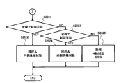
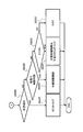
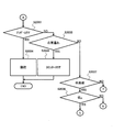
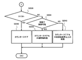
図8-図15は、第1姿勢制御部16-8による制動及び操舵の制御、つまり、ステップS2000での処理内容を示すフローチャートである。
第1姿勢制御部16-8は、まず、ステップS2001で、自車位置が目標の旋回軌跡の外側であるか内側であるかを判断する。
第1姿勢制御部16-8は、まず、ステップS2001で、自車位置が目標の旋回軌跡の外側であるか内側であるかを判断する。
そして、自車位置が目標の旋回軌跡の外側である場合、第1姿勢制御部16-8は、ステップS2002に進み、自車挙動がアンダーステア傾向であるか否かを判断する。
ここで、自車挙動がアンダーステア傾向であれば、第1姿勢制御部16-8は、ステップS2003に進み、操舵制御の応答遅れがあるか否かを判断する。
ここで、自車挙動がアンダーステア傾向であれば、第1姿勢制御部16-8は、ステップS2003に進み、操舵制御の応答遅れがあるか否かを判断する。
なお、操舵制御の応答遅れは目標舵角への実舵角の追従遅れで、第1姿勢制御部16-8は、例えば、目標舵角の変化に対して実舵角が追従するときの時定数などに基づき、操舵制御における応答遅れの有無を判断することができる。
例えば、第1姿勢制御部16-8は、目標舵角の変化に対して実舵角が追従するときの時定数が判定値よりも大きいときに、操舵制御の応答遅れがあると判断する。
例えば、第1姿勢制御部16-8は、目標舵角の変化に対して実舵角が追従するときの時定数が判定値よりも大きいときに、操舵制御の応答遅れがあると判断する。
操舵制御の応答遅れがある場合、第1姿勢制御部16-8は、ステップS2004に進み、操舵制御によって車両100の進行方向をより旋回内側に向けてアンダーステア傾向を抑制する。
なお、操舵制御の応答遅れに因るアンダーステア傾向であるため、第1姿勢制御部16-8は、ステップS2004で、操舵装置13の制御量を増やして舵角δの増大を促進させる。
なお、操舵制御の応答遅れに因るアンダーステア傾向であるため、第1姿勢制御部16-8は、ステップS2004で、操舵装置13の制御量を増やして舵角δの増大を促進させる。
一方、第1姿勢制御部16-8は、ステップS2003で操舵制御の応答遅れが充分に小さいと判断した場合、ステップS2005に進み、車速が所定速度(中速)又は所定速度(中速)より速いか否か、換言すれば、車両100が中高速で走行しているか否かを判断する。
車速が所定速度又は所定速度より速く、車両100が中高速で走行している場合、第1姿勢制御部16-8は、ステップS2006に進み、アンダーステア傾向の抑制に必要なヨーモーメントが、後輪への制動力配分で発生可能なヨーモーメントであるか否かを判断する。
なお、第1姿勢制御部16-8は、必要ヨーモーメントを、挙動修正モーメント、フィードフォワード操作量及びフィードバック操作量などから求める。
車速が所定速度又は所定速度より速く、車両100が中高速で走行している場合、第1姿勢制御部16-8は、ステップS2006に進み、アンダーステア傾向の抑制に必要なヨーモーメントが、後輪への制動力配分で発生可能なヨーモーメントであるか否かを判断する。
なお、第1姿勢制御部16-8は、必要ヨーモーメントを、挙動修正モーメント、フィードフォワード操作量及びフィードバック操作量などから求める。
そして、必要なヨーモーメントを後輪への制動力配分で発生させることができる場合、第1姿勢制御部16-8は、ステップS2007に進み、旋回内側の後輪に制動力を付与して、アンダーステア傾向を抑制する方向のヨーモーメントを発生させる。
車速が中速又は高速であればヨーモーメントを発生させるために制動力を付与しても制動感が出難いので、第1姿勢制御部16-8は、ステップS2007で、主に制動を制御することでアンダーステア傾向を抑制するためのヨーモーメントを発生させる。
車速が中速又は高速であればヨーモーメントを発生させるために制動力を付与しても制動感が出難いので、第1姿勢制御部16-8は、ステップS2007で、主に制動を制御することでアンダーステア傾向を抑制するためのヨーモーメントを発生させる。
一方、必要なヨーモーメントを後輪への制動力配分で発生させることができない場合、第1姿勢制御部16-8は、ステップS2008に進み、必要なヨーモーメントを前輪への制動力配分で発生させることができるか否かを判断する。
そして、必要なヨーモーメントを前輪への制動力配分で発生させることができる場合、第1姿勢制御部16-8は、ステップS2009へ進み、旋回内側の後輪及び前輪に制動力を付与して、アンダーステア傾向を抑制する方向のヨーモーメントを発生させる。
そして、必要なヨーモーメントを前輪への制動力配分で発生させることができる場合、第1姿勢制御部16-8は、ステップS2009へ進み、旋回内側の後輪及び前輪に制動力を付与して、アンダーステア傾向を抑制する方向のヨーモーメントを発生させる。
また、必要なヨーモーメントを前輪への制動力配分で発生させることができない場合、第1姿勢制御部16-8は、ステップS2010に進み、操舵によって発生可能な最大横力に余裕分を付加した横力相当の舵角である閾値δmと、実車の舵角δ(以下、実舵角δという)とを比較し、実舵角δが閾値δmに一致するか又は閾値δmより小さいかを判断する。
つまり、第1姿勢制御部16-8は、実舵角δが閾値δmに一致するか又は閾値δmより小さい場合、操舵制御によってアンダーステア傾向を抑制するためのヨーモーメントを与えることができると推定する。
一方、第1姿勢制御部16-8は、実舵角δが閾値δmを超えている場合、操舵制御ではアンダーステア傾向を抑制するためのヨーモーメントを充分に与えることができないと推定する。
つまり、第1姿勢制御部16-8は、実舵角δが閾値δmに一致するか又は閾値δmより小さい場合、操舵制御によってアンダーステア傾向を抑制するためのヨーモーメントを与えることができると推定する。
一方、第1姿勢制御部16-8は、実舵角δが閾値δmを超えている場合、操舵制御ではアンダーステア傾向を抑制するためのヨーモーメントを充分に与えることができないと推定する。
ここで、操舵制御によってアンダーステア傾向を抑制するためのヨーモーメントを与えることができる状態であれば、第1姿勢制御部16-8は、ステップS2011に進む。
ステップS2011で、第1姿勢制御部16-8は、旋回内側の後輪及び前輪に制動力を付与し、更に、実舵角δを増やして、車両100の進行方向をより旋回内側に向けるヨーモーメントを与え、アンダーステア傾向を抑制する。
ステップS2011で、第1姿勢制御部16-8は、旋回内側の後輪及び前輪に制動力を付与し、更に、実舵角δを増やして、車両100の進行方向をより旋回内側に向けるヨーモーメントを与え、アンダーステア傾向を抑制する。
一方、第1姿勢制御部16-8は、実舵角δが閾値δmを超えていて、操舵制御を行ってもアンダーステア傾向を抑制するためのヨーモーメントを充分に与えることができない場合、ステップS2012に進む。
ステップS2012で、第1姿勢制御部16-8は、実舵角δを増大させ、かつ、4輪に制動力を付与して減速させ、更に、ホイルシリンダ液圧制御装置11(横滑り防止装置)からの挙動修正モーメントに基づくホイルシリンダ5-8の液圧調整を行わせる。
なお、第1姿勢制御部16-8は、ステップS2012で、第2姿勢制御部16-9による制動及び駆動の制御への移行を実施することができる。
ステップS2012で、第1姿勢制御部16-8は、実舵角δを増大させ、かつ、4輪に制動力を付与して減速させ、更に、ホイルシリンダ液圧制御装置11(横滑り防止装置)からの挙動修正モーメントに基づくホイルシリンダ5-8の液圧調整を行わせる。
なお、第1姿勢制御部16-8は、ステップS2012で、第2姿勢制御部16-9による制動及び駆動の制御への移行を実施することができる。
また、第1姿勢制御部16-8は、ステップS2005で、車速が所定速度を下回る低速状態であると判断すると、ステップS2013(図9参照)に進む。
ステップS2013で、第1姿勢制御部16-8は、実舵角δが、操舵によって発生可能な最大横力に相当する閾値δmaに一致するか又は閾値δmaより小さいかを判断する。
ステップS2013で、第1姿勢制御部16-8は、実舵角δが、操舵によって発生可能な最大横力に相当する閾値δmaに一致するか又は閾値δmaより小さいかを判断する。
そして、実舵角δが閾値δmaに一致するか又は閾値δmaより小さい場合、第1姿勢制御部16-8は、操舵制御によってアンダーステア傾向を抑制するためのヨーモーメントを発生させ得る状態であると判断し、ステップS2014に進む。
ステップS2014で、第1姿勢制御部16-8は、実舵角δを増やして車両100の進行方向をより旋回内側に向けるヨーモーメントを与え、車両挙動のアンダーステア傾向を抑制する。
ステップS2014で、第1姿勢制御部16-8は、実舵角δを増やして車両100の進行方向をより旋回内側に向けるヨーモーメントを与え、車両挙動のアンダーステア傾向を抑制する。
一方、実舵角δが閾値δmaを超える場合、第1姿勢制御部16-8は、ステップS2015に進み、実舵角δが閾値δm(δm>δma)より小さいか否かを判断する。
ここで、実舵角δが閾値δmより小さい場合、第1姿勢制御部16-8は、ステップS2016に進み、アンダーステア傾向の抑制に必要なヨーモーメントが後輪への制動力配分で発生可能なヨーモーメントであるか否かを判断する。
そして、アンダーステア傾向の抑制に必要なヨーモーメントが後輪への制動力配分で発生可能なヨーモーメントである場合、第1姿勢制御部16-8は、ステップS2017に進み、実舵角δを増やすとともに旋回内側の後輪に制動力を付与して、アンダーステア傾向を抑制する方向のヨーモーメントを与える。
ここで、実舵角δが閾値δmより小さい場合、第1姿勢制御部16-8は、ステップS2016に進み、アンダーステア傾向の抑制に必要なヨーモーメントが後輪への制動力配分で発生可能なヨーモーメントであるか否かを判断する。
そして、アンダーステア傾向の抑制に必要なヨーモーメントが後輪への制動力配分で発生可能なヨーモーメントである場合、第1姿勢制御部16-8は、ステップS2017に進み、実舵角δを増やすとともに旋回内側の後輪に制動力を付与して、アンダーステア傾向を抑制する方向のヨーモーメントを与える。
また、第1姿勢制御部16-8は、ステップS2016で、アンダーステア傾向の抑制に必要なヨーモーメントが後輪への制動力配分で発生可能なヨーモーメントをよりも大きいと判断すると、ステップS2018に進む。
第1姿勢制御部16-8は、ステップS2018で、アンダーステア傾向の抑制に必要なヨーモーメントを前輪への制動力配分で発生させることができるか否かを判断する。
そして、アンダーステア傾向の抑制に必要なヨーモーメントを前輪への制動力配分で発生させることができる場合、第1姿勢制御部16-8は、ステップS2019に進み、実舵角δを増やすとともに旋回内側の後輪及び前輪に制動力を付与して、アンダーステア傾向を抑制する方向のヨーモーメントを与える。
第1姿勢制御部16-8は、ステップS2018で、アンダーステア傾向の抑制に必要なヨーモーメントを前輪への制動力配分で発生させることができるか否かを判断する。
そして、アンダーステア傾向の抑制に必要なヨーモーメントを前輪への制動力配分で発生させることができる場合、第1姿勢制御部16-8は、ステップS2019に進み、実舵角δを増やすとともに旋回内側の後輪及び前輪に制動力を付与して、アンダーステア傾向を抑制する方向のヨーモーメントを与える。
また、アンダーステア傾向の抑制に必要なヨーモーメントを前輪への制動力配分で発生させることができない場合、第1姿勢制御部16-8は、ステップS2020に進み、旋回内側の後輪及び前輪の制動力を所定の限界値まで増やした後、実舵角δを所定の限界値まで増やし、アンダーステア傾向の抑制を図る。
また、第1姿勢制御部16-8は、ステップS2015で、実舵角δが閾値δmに一致するか又は閾値δmより大きいと判断すると、ステップS2021(図10参照)に進み、アンダーステア傾向の抑制に必要なヨーモーメントが後輪への制動力配分で発生可能なヨーモーメントであるか否かを判断する。
そして、アンダーステア傾向の抑制に必要なヨーモーメントが後輪への制動力配分で発生可能なヨーモーメントであれば、第1姿勢制御部16-8は、ステップS2022に進んで、実舵角δが所定の限界値に達している状態で、ヨーモーメントの不足分を旋回内側の後輪に制動力を付与して発生させる。
また、第1姿勢制御部16-8は、ステップS2015で、実舵角δが閾値δmに一致するか又は閾値δmより大きいと判断すると、ステップS2021(図10参照)に進み、アンダーステア傾向の抑制に必要なヨーモーメントが後輪への制動力配分で発生可能なヨーモーメントであるか否かを判断する。
そして、アンダーステア傾向の抑制に必要なヨーモーメントが後輪への制動力配分で発生可能なヨーモーメントであれば、第1姿勢制御部16-8は、ステップS2022に進んで、実舵角δが所定の限界値に達している状態で、ヨーモーメントの不足分を旋回内側の後輪に制動力を付与して発生させる。
また、アンダーステア傾向の抑制に必要なヨーモーメントが後輪への制動力配分で発生可能なヨーモーメントを超えている場合、第1姿勢制御部16-8は、ステップS2023に進み、アンダーステア傾向の抑制に必要なヨーモーメントを前輪への制動力配分で発生させることができるか否かを判断する。
そして、アンダーステア傾向の抑制に必要なヨーモーメントを前輪への制動力配分で発生させることができる場合、第1姿勢制御部16-8は、ステップS2024に進み、実舵角δが所定の限界値に達している状態で、ヨーモーメントの不足分を旋回内側の後輪及び前輪に制動力を付与して発生させる。
そして、アンダーステア傾向の抑制に必要なヨーモーメントを前輪への制動力配分で発生させることができる場合、第1姿勢制御部16-8は、ステップS2024に進み、実舵角δが所定の限界値に達している状態で、ヨーモーメントの不足分を旋回内側の後輪及び前輪に制動力を付与して発生させる。
一方、アンダーステア傾向の抑制に必要なヨーモーメントを前輪への制動力配分で発生させることができない場合、第1姿勢制御部16-8は、ステップS2023からステップS2025に進み、実舵角δが所定の限界値に達している状態で、4輪に制動力を付与して減速させ、更に、ホイルシリンダ液圧制御装置11(横滑り防止装置)からの挙動修正モーメントに基づくホイルシリンダ5-8の液圧調整を行わせる。
なお、第1姿勢制御部16-8は、ステップS2025で、第2姿勢制御部16-9による車両z軸姿勢制御(制動及び駆動の制御)への移行を実施することができる。
なお、第1姿勢制御部16-8は、ステップS2025で、第2姿勢制御部16-9による車両z軸姿勢制御(制動及び駆動の制御)への移行を実施することができる。
また、第1姿勢制御部16-8は、ステップS2002で、自車挙動がアンダーステア傾向ではなくオーバーステア傾向であると判断すると、ステップS2026(図11参照)に進み、操舵制御の応答遅れがあるか否かを判断する。
そして、操舵制御の応答遅れがある場合、第1姿勢制御部16-8は、ステップS2027に進み、進行方向とは逆に操舵する操舵制御(カウンターステア)を実施してオーバーステア傾向を抑制する。
なお、操舵制御の応答遅れがあるので、第1姿勢制御部16-8は、ステップS2027で、操舵装置13の制御量を増やして舵角δの戻しを促進させる。
そして、操舵制御の応答遅れがある場合、第1姿勢制御部16-8は、ステップS2027に進み、進行方向とは逆に操舵する操舵制御(カウンターステア)を実施してオーバーステア傾向を抑制する。
なお、操舵制御の応答遅れがあるので、第1姿勢制御部16-8は、ステップS2027で、操舵装置13の制御量を増やして舵角δの戻しを促進させる。
一方、操舵制御の応答遅れが充分に小さい場合、第1姿勢制御部16-8は、ステップS2028に進み、目標軌跡の外側でのオーバーステア傾向を抑制するのに必要なヨーモーメントを前輪への制動力配分で発生させることができるか否かを判断する。
ここで、必要ヨーモーメントを前輪への制動力配分で発生させることができる場合、第1姿勢制御部16-8は、ステップS2029に進み、旋回外側の前輪に制動力を付与してオーバーステア傾向を抑制するヨーモーメントを与える。
ここで、必要ヨーモーメントを前輪への制動力配分で発生させることができる場合、第1姿勢制御部16-8は、ステップS2029に進み、旋回外側の前輪に制動力を付与してオーバーステア傾向を抑制するヨーモーメントを与える。
また、必要ヨーモーメントを前輪への制動力配分で発生させることができない場合、第1姿勢制御部16-8は、ステップS2030に進み、実舵角δが実車体滑り角βに所定角度Δθを加算した角度δth(δth=β+Δθ)より小さいか否かを判断する。
そして、実舵角δが角度δthより小さい場合、第1姿勢制御部16-8は、ステップS2031に進み、旋回外側の前輪に制動力を付与してオーバーステア傾向を抑制するヨーモーメントを与え、係る制動力制御で不足する分のヨーモーメントを、角度δthを限界とするカウンターステアで補う。
そして、実舵角δが角度δthより小さい場合、第1姿勢制御部16-8は、ステップS2031に進み、旋回外側の前輪に制動力を付与してオーバーステア傾向を抑制するヨーモーメントを与え、係る制動力制御で不足する分のヨーモーメントを、角度δthを限界とするカウンターステアで補う。
また、実舵角δが角度δthに一致するか又は角度δthより大きい場合、第1姿勢制御部16-8は、ステップS2032に進み、ホイルシリンダ液圧制御装置11(横滑り防止装置)からの挙動修正モーメントに基づくホイルシリンダ5-8の液圧調整を実施するか、又は、第2姿勢制御部16-9による車両z軸姿勢制御(制動及び駆動の制御)に移行する。
以上の処理は、第1姿勢制御部16-8が、ステップS2001で、自車位置が目標の旋回軌跡の外側であると判断した場合の処理になる。
以上の処理は、第1姿勢制御部16-8が、ステップS2001で、自車位置が目標の旋回軌跡の外側であると判断した場合の処理になる。
第1姿勢制御部16-8は、ステップS2001で、自車位置が目標の旋回軌跡の内側であると判断すると、ステップS2033(図12参照)に進む。
ステップS2033で、第1姿勢制御部16-8は、車両100の旋回挙動がアンダーステア傾向であるか否かを判断する。
そして、自車挙動がアンダーステア傾向である場合、第1姿勢制御部16-8は、ステップS2034に進み、実舵角δを増大させる操舵制御によってアンダーステア傾向を抑制する。
ステップS2033で、第1姿勢制御部16-8は、車両100の旋回挙動がアンダーステア傾向であるか否かを判断する。
そして、自車挙動がアンダーステア傾向である場合、第1姿勢制御部16-8は、ステップS2034に進み、実舵角δを増大させる操舵制御によってアンダーステア傾向を抑制する。
一方、自車位置が目標の旋回軌跡の内側で、かつ、車両100の旋回挙動がオーバーステア傾向である場合、第1姿勢制御部16-8は、ステップS2035に進み、操舵制御の応答遅れがあるか否かを判断する。
そして、操舵制御の応答遅れがある場合、第1姿勢制御部16-8は、ステップS2036に進み、操舵制御としてカウンターステアを行い、オーバーステア傾向を抑制する。
なお、操舵制御の応答遅れがあるので、第1姿勢制御部16-8は、ステップS2036で、操舵装置13の制御量を増やして実舵角δの戻しを促進させる。
そして、操舵制御の応答遅れがある場合、第1姿勢制御部16-8は、ステップS2036に進み、操舵制御としてカウンターステアを行い、オーバーステア傾向を抑制する。
なお、操舵制御の応答遅れがあるので、第1姿勢制御部16-8は、ステップS2036で、操舵装置13の制御量を増やして実舵角δの戻しを促進させる。
また、操舵制御の応答遅れが充分に小さい場合、第1姿勢制御部16-8は、ステップS2035からステップS2037に進んで、車速が所定速度(中速)又は所定速度より速い中高速状態であるか否かを判断する。
車速が中高速である場合、第1姿勢制御部16-8は、ステップS2038に進み、車両100が走行している路面の摩擦係数μが所定値又は所定値より小さいか否か、つまり、車両100が濡れた路面や雪道などの滑り易い路面を走行しているか否かを判断する。
第1姿勢制御部16-8は、路面の摩擦係数μの情報を、車輪1-4のスリップなどの走行状態から推定したり、車両100に搭載された他の電子制御装置から車両内ネットワークを介して取得したり、車両100の外部の装置から無線通信で取得したりすることができる。
車速が中高速である場合、第1姿勢制御部16-8は、ステップS2038に進み、車両100が走行している路面の摩擦係数μが所定値又は所定値より小さいか否か、つまり、車両100が濡れた路面や雪道などの滑り易い路面を走行しているか否かを判断する。
第1姿勢制御部16-8は、路面の摩擦係数μの情報を、車輪1-4のスリップなどの走行状態から推定したり、車両100に搭載された他の電子制御装置から車両内ネットワークを介して取得したり、車両100の外部の装置から無線通信で取得したりすることができる。
車両100の位置が目標の旋回軌跡の内側で、車両100の旋回挙動がオーバーステア傾向で、かつ、車両100が中高速で滑り易い路面を走行している場合、第1姿勢制御部16-8は、ステップS2038からステップS2039(図13参照)に進む。
ステップS2039で、第1姿勢制御部16-8は、実舵角δが、実車体滑り角βに所定角度Δθを加算した角度δthより小さいか否かを判断する。
そして、実舵角δが角度δthより小さい場合、第1姿勢制御部16-8は、ステップS2040に進み、操舵制御として角度δthを限界とするカウンターステアを行い、オーバーステア傾向を抑制する。
ステップS2039で、第1姿勢制御部16-8は、実舵角δが、実車体滑り角βに所定角度Δθを加算した角度δthより小さいか否かを判断する。
そして、実舵角δが角度δthより小さい場合、第1姿勢制御部16-8は、ステップS2040に進み、操舵制御として角度δthを限界とするカウンターステアを行い、オーバーステア傾向を抑制する。
一方、実舵角δが角度δth又は角度δthより大きい場合、第1姿勢制御部16-8は、ステップS2041に進み、目標軌跡の内側でのオーバーステア傾向を抑制するのに必要なヨーモーメントを前輪への制動力配分で発生させることができるか否かを判断する。
ここで、必要ヨーモーメントを前輪への制動力配分で発生させることができる場合、第1姿勢制御部16-8は、ステップS2042に進み、カウンターステアが限界である角度δthに達している状態で、旋回外側の前輪に制動力を付与する制動制御を行い、オーバーステア傾向を抑制する。
また、必要ヨーモーメントを前輪への制動力配分で発生させることができない場合、第1姿勢制御部16-8は、ステップS2043に進み、カウンターステアが限界である角度δthに達している状態で、旋回外側の前輪に限界以上の制動力を付与する制動制御を行い、オーバーステア傾向を抑制する。
ここで、必要ヨーモーメントを前輪への制動力配分で発生させることができる場合、第1姿勢制御部16-8は、ステップS2042に進み、カウンターステアが限界である角度δthに達している状態で、旋回外側の前輪に制動力を付与する制動制御を行い、オーバーステア傾向を抑制する。
また、必要ヨーモーメントを前輪への制動力配分で発生させることができない場合、第1姿勢制御部16-8は、ステップS2043に進み、カウンターステアが限界である角度δthに達している状態で、旋回外側の前輪に限界以上の制動力を付与する制動制御を行い、オーバーステア傾向を抑制する。
一方、目標軌跡の内側での車両挙動がオーバーステア傾向で、かつ、摩擦係数μが所定値を超えるドライ路面を車両100が中高速で走行している場合、第1姿勢制御部16-8は、ステップS2038からステップS2044(図14参照)に進む。
ステップS2044で、第1姿勢制御部16-8は、目標軌跡の内側でのオーバーステア傾向を抑制するのに必要なヨーモーメントを前輪への制動力配分で与えることができるか否かを判断する。
ステップS2044で、第1姿勢制御部16-8は、目標軌跡の内側でのオーバーステア傾向を抑制するのに必要なヨーモーメントを前輪への制動力配分で与えることができるか否かを判断する。
そして、必要ヨーモーメントを前輪への制動力配分で与えることができる場合、第1姿勢制御部16-8は、ステップS2045に進み、旋回外側の前輪に制動力を付与する制動制御を行い、オーバーステア傾向を抑制する。
ここで、車速が中高速であるときは、カウンターステア後に舵角δの戻し遅れや誤差に不安定挙動を誘発するのを極力避ける為、第1姿勢制御部16-8では、ステップS2045で、旋回用の舵角δに制御してカウンターステアは行わない。
ここで、車速が中高速であるときは、カウンターステア後に舵角δの戻し遅れや誤差に不安定挙動を誘発するのを極力避ける為、第1姿勢制御部16-8では、ステップS2045で、旋回用の舵角δに制御してカウンターステアは行わない。
また、第1姿勢制御部16-8は、ステップS2044で、必要ヨーモーメントを前輪への制動力配分で発生させることができないと判断すると、ステップS2046に進む。
ステップS2046で、第1姿勢制御部16-8は、実舵角δが車体滑り角βに所定角度Δθを加算した角度δthより小さいか否かを判断する。
そして、実舵角δが角度δthより小さい場合、第1姿勢制御部16-8は、ステップS2047に進み、旋回外側の前輪に制動力を付与し、係る制動制御で発生させることができるヨーモーメントではオーバーステア傾向の抑制に不十分である場合は、角度δthを限界とするカウンターステアを行って、オーバーステア傾向を抑制する。
ステップS2046で、第1姿勢制御部16-8は、実舵角δが車体滑り角βに所定角度Δθを加算した角度δthより小さいか否かを判断する。
そして、実舵角δが角度δthより小さい場合、第1姿勢制御部16-8は、ステップS2047に進み、旋回外側の前輪に制動力を付与し、係る制動制御で発生させることができるヨーモーメントではオーバーステア傾向の抑制に不十分である場合は、角度δthを限界とするカウンターステアを行って、オーバーステア傾向を抑制する。
一方、実舵角δが角度δth又は角度δthより大きい場合、第1姿勢制御部16-8は、ステップS2048に進み、角度δthを限界とするカウンターステアを行い、また、4輪に制動力を付与して減速させ、更に、ホイルシリンダ液圧制御装置11(横滑り防止装置)からの挙動修正モーメントに基づくホイルシリンダ5-8の液圧調整を行わせる。
なお、第1姿勢制御部16-8は、ステップS2048で、第2姿勢制御部16-9による車両z軸姿勢制御(制動及び駆動の制御)への移行を実施することができる。
なお、第1姿勢制御部16-8は、ステップS2048で、第2姿勢制御部16-9による車両z軸姿勢制御(制動及び駆動の制御)への移行を実施することができる。
また、目標軌跡の内側での車両挙動がオーバーステア傾向で、かつ、車両100が低速で走行している場合、第1姿勢制御部16-8は、ステップS2037からステップS2049(図15参照)に進む。
ステップS2049で、第1姿勢制御部16-8は、実舵角δが車体滑り角βに所定角度Δθを加算した角度δthより小さいか否かを判断する。
そして、実舵角δが角度δthより小さい場合、第1姿勢制御部16-8は、ステップS2050に進み、角度δthを限界とするカウンターステアを行ってオーバーステア傾向を抑制する。
ステップS2049で、第1姿勢制御部16-8は、実舵角δが車体滑り角βに所定角度Δθを加算した角度δthより小さいか否かを判断する。
そして、実舵角δが角度δthより小さい場合、第1姿勢制御部16-8は、ステップS2050に進み、角度δthを限界とするカウンターステアを行ってオーバーステア傾向を抑制する。
一方、実舵角δが角度δth又は角度δthより大きい場合、第1姿勢制御部16-8は、ステップS2051に進み、目標軌跡の内側でのオーバーステア傾向を抑制するのに必要なヨーモーメントを前輪への制動力配分で発生させることができるか否かを判断する。
ここで、必要ヨーモーメントを前輪への制動力配分で発生させることができる場合、第1姿勢制御部16-8は、ステップS2052に進み、角度δthを限界とするカウンターステアを行うとともに、旋回外側の前輪に制動力を付与する制動制御を行って、オーバーステア傾向を抑制する。
ここで、必要ヨーモーメントを前輪への制動力配分で発生させることができる場合、第1姿勢制御部16-8は、ステップS2052に進み、角度δthを限界とするカウンターステアを行うとともに、旋回外側の前輪に制動力を付与する制動制御を行って、オーバーステア傾向を抑制する。
また、必要ヨーモーメントを前輪への制動力配分で発生させることができない場合、第1姿勢制御部16-8は、ステップS2053に進み、角度δthを限界とするカウンターステアを行い、また、4輪に制動力を付与して減速させ、更に、ホイルシリンダ液圧制御装置11(横滑り防止装置)からの挙動修正モーメントに基づくホイルシリンダ5-8の液圧調整を行わせる。
なお、第1姿勢制御部16-8は、ステップS2053で、第2姿勢制御部16-9による車両z軸姿勢制御(制動及び駆動の制御)への移行を実施することができる。
なお、第1姿勢制御部16-8は、ステップS2053で、第2姿勢制御部16-9による車両z軸姿勢制御(制動及び駆動の制御)への移行を実施することができる。
上記実施形態で説明した各技術的思想は、矛盾が生じない限りにおいて、適宜組み合わせて使用することができる。
また、好ましい実施形態を参照して本発明の内容を具体的に説明したが、本発明の基本的技術思想及び教示に基づいて、当業者であれば、種々の変形態様を採り得ることは自明である。
また、好ましい実施形態を参照して本発明の内容を具体的に説明したが、本発明の基本的技術思想及び教示に基づいて、当業者であれば、種々の変形態様を採り得ることは自明である。
例えば、比較部16-6は、目標z軸姿勢値ZPOGと線形モデルz軸姿勢値ZPLMとの偏差の絶対値と比較する閾値ΔZPを、路面の摩擦係数や勾配、車速の条件などに応じて可変に設定することができる。つまり、第1姿勢制御部16-8、第2姿勢制御部16-9の選択条件は、目標z軸姿勢値ZPOGと線形モデルz軸姿勢値ZPLMとの偏差のみに限定されず、偏差に加えて、路面条件や走行条件を選択条件とすることができる。
また、姿勢制御部16-3は、第2姿勢制御部16-9によって姿勢制御を行っていることを、車両100の運転者にランプなどで通知することができる。
また、図6のフローチャートに示した第2姿勢制御部16-9による制動及び駆動の制御では、条件に応じて制動と駆動とのいずれか一方を主に制御するが、制動及び駆動を並行して制御して姿勢制御を行うことができる。
また、図6のフローチャートに示した第2姿勢制御部16-9による制動及び駆動の制御では、条件に応じて制動と駆動とのいずれか一方を主に制御するが、制動及び駆動を並行して制御して姿勢制御を行うことができる。
すなわち、本発明は上記した実施形態に限定されるものではなく、様々な変形例が含まれる。例えば、上記した実施形態は本発明を分かりやすく説明するために詳細に説明したものであり、必ずしも説明した全ての構成を備えるものに限定されるものではない。また、ある実施形態の構成の一部を他の実施形態の構成に置き換えることが可能であり、また、ある実施形態の構成に他の実施形態の構成を加えることも可能である。また、各実施形態の構成の一部について、他の構成の追加・削除・置換をすることが可能である。
本願は、2019年3月8日付出願の日本国特許出願第2019-042656号に基づく優先権を主張する。2019年3月8日付出願の日本国特許出願第2019-042656号の明細書、特許請求の範囲、図面、および要約書を含む全開示内容は、参照により本願に全体として組み込まれる。
10…制動力発生装置、13…操舵装置、14…自動運転制御装置、16…車両統合運動制御装置、16-1…FF操作量演算部、16-2…FB操作量演算部、16-3…姿勢制御部、16-4…目標z軸姿勢演算部、16-5…線形モデルz軸姿勢演算部、16-6…比較部、16-7…切換え部、16-8…第1姿勢制御部、16-9…第2姿勢制御部、100…車両
Claims (13)
- 車両運動制御装置であって、
入力された情報に基づいて演算を行い、演算した結果を出力するコントロール部を備え、
前記コントロール部は、
目標軌跡を含む走行目標に応じて走行するための車両の運動状態をモデル化した車両運動モデルに基づいて、前記車両の操作に必要な操作量である第1制御量を求め、
前記第1制御量と、前記車両の実運動状態を検出する車両運動状態検出センサから入力された前記実運動状態と、に基づき前記車両の操作量である第2制御量を求め、
前記第2制御量と、前記目標軌跡に基づく目標車両姿勢に関する物理量と、前記車両の線形モデルに基づく線形モデル車両姿勢に関する物理量と、に基づき前記車両の制動、駆動および操舵に関わる操作量の制御指令を求め、
前記制御指令を前記制動、駆動および操舵に関わるアクチュエータ部に出力する、
車両運動制御装置。 - 請求項1に記載の車両運動制御装置であって、
前記目標車両姿勢に関する物理量および前記線形モデル車両姿勢に関する物理量は前記車両のヨー方向の姿勢に関する物理量である、
車両運動制御装置。 - 請求項1に記載の車両運動制御装置であって、
前記コントロール部は、
前記目標車両姿勢に関する物理量と前記線形モデル車両姿勢に関する物理量との比較結果に基づき、前記車両の制動、駆動および操舵に関わる操作量から前記制御指令を選択する、
車両運動制御装置。 - 請求項3に記載の車両運動制御装置であって、
前記コントロール部は、
前記制御指令を、
前記目標車両姿勢に関する物理量と前記線形モデル車両姿勢に関する物理量との差が閾値を超えるときは、前記制動および前記駆動に関する操作量とし、
前記差が前記閾値に一致するか又は前記閾値より小さいときは、前記制動および前記操舵に関する操作量とする、
車両運動制御装置。 - 請求項4に記載の車両運動制御装置であって、
前記コントロール部は、
前記差が前記閾値を超えるとき、
前記制御指令を、
前記車両が加速中であるときは、前記駆動に関する操作量とし、
前記車両が加速中でないときは、前記制動に関する操作量とする、
車両運動制御装置。 - 請求項4に記載の車両運動制御装置であって、
前記コントロール部は、
前記差が前記閾値を超え、かつ、前記目標軌跡に対して前記車両が旋回外向きであるとき、
前記制御指令を、
車体滑り角が所定角に一致するか又は前記所定角を下回るとき、前記制動に関する操作量とし、
前記車体滑り角が前記所定角を超え、かつ、前記車両が加速中であるとき、前記駆動に関する操作量とし、
前記車体滑り角が前記所定角を超え、かつ、前記車両が加速中でないとき、前記制動に関する操作量とする、
車両運動制御装置。 - 請求項4に記載の車両運動制御装置であって、
前記コントロール部は、
前記差が前記閾値を超え、かつ、前記目標軌跡に対して前記車両が旋回内向きであるとき、
前記制御指令を、
車体滑り角が所定角に一致するか又は前記所定角を下回るとき、前記駆動に関する操作量とし、
前記車体滑り角が前記所定角を超え、かつ、前記車両が加速中であるとき、前記駆動に関する操作量とし、
前記車体滑り角が前記所定角を超え、かつ、前記車両が加速中でないとき、前記制動に関する操作量とする、
車両運動制御装置。 - 請求項1に記載の車両運動制御装置であって、
前記コントロール部は、
前記制御指令を、
前記車両の挙動の大きさを表す物理量が所定値を超えると、前記制動に関する操作量とする、
車両運動制御装置。 - 車両運動制御方法であって、
目標軌跡を含む走行目標に応じて走行するための車両の運動状態をモデル化した車両運動モデルに基づいて、前記車両の操作に必要な操作量である第1制御量を求めることと、
前記第1制御量と、前記車両の実運動状態を検出する車両運動状態検出センサで検出された前記実運動状態と、に基づき前記車両の操作量である第2制御量を求めることと、
前記第2制御量と、前記目標軌跡に基づく目標車両姿勢に関する物理量と、前記車両の線形モデルに基づく線形モデル車両姿勢に関する物理量と、に基づき前記車両の制動、駆動および操舵に関わる操作量の制御指令を求めることと、
前記制御指令を前記制動、駆動および操舵に関わるアクチュエータ部に出力することと、
を有する車両運動制御方法。 - 請求項9に記載の車両運動制御方法であって、
前記目標車両姿勢に関する物理量および前記線形モデル車両姿勢に関する物理量は前記車両のヨー方向の姿勢に関する物理量である、
車両運動制御方法。 - 請求項9に記載の車両運動制御方法であって、
前記制御指令を求めることにおいて、
前記目標車両姿勢に関する物理量と前記線形モデル車両姿勢に関する物理量との比較結果に基づき、前記車両の制動、駆動および操舵に関わる操作量から前記制御指令を選択する、
車両運動制御方法。 - 請求項11に記載の車両運動制御方法であって、
前記制御指令を求めることにおいて、
前記制御指令を、
前記目標車両姿勢に関する物理量と前記線形モデル車両姿勢に関する物理量との差が閾値を超えるときは、前記制動および前記駆動に関する操作量とし、
前記差が前記閾値に一致するか又は前記閾値より小さいときは、前記制動および前記操舵に関する操作量とする、
車両運動制御方法。 - 車両運動制御システムであって、
車両の実運動状態を検出する車両運動状態検出センサと、
コントロール部であって、
目標軌跡を含む走行目標に応じて走行するための前記車両の運動状態をモデル化した車両運動モデルに基づいて、前記車両の操作に必要な操作量である第1制御量を求め、
前記第1制御量と、前記車両運動状態検出センサから入力された前記実運動状態と、に基づき前記車両の操作量である第2制御量を求め、
前記第2制御量と、前記目標軌跡に基づく目標車両姿勢に関する物理量と、前記車両の線形モデルに基づく線形モデル車両姿勢に関する物理量と、に基づき前記車両の制動、駆動および操舵に関わる操作量の制御指令を求め、
前記制御指令を出力する、
コントロール部と、
前記コントロール部から出力された前記制御指令を取得する前記車両の制動、駆動および操舵に関わるアクチュエータ部と、
を備える車両運動制御システム。
Priority Applications (2)
| Application Number | Priority Date | Filing Date | Title |
|---|---|---|---|
| US17/436,778 US11745706B2 (en) | 2019-03-08 | 2020-01-30 | Vehicle motion control device, vehicle motion control method, and vehicle motion control system |
| DE112020001117.8T DE112020001117T5 (de) | 2019-03-08 | 2020-01-30 | Fahrzeugbewegungssteuervorrichtung, fahrzeugbewegungssteuerverfahrenund fahrzeugbewegungssteuersystem |
Applications Claiming Priority (2)
| Application Number | Priority Date | Filing Date | Title |
|---|---|---|---|
| JP2019042656A JP7216579B2 (ja) | 2019-03-08 | 2019-03-08 | 車両運動制御装置、車両運動制御方法、及び車両運動制御システム |
| JP2019-042656 | 2019-03-08 |
Publications (1)
| Publication Number | Publication Date |
|---|---|
| WO2020183963A1 true WO2020183963A1 (ja) | 2020-09-17 |
Family
ID=72353069
Family Applications (1)
| Application Number | Title | Priority Date | Filing Date |
|---|---|---|---|
| PCT/JP2020/003406 Ceased WO2020183963A1 (ja) | 2019-03-08 | 2020-01-30 | 車両運動制御装置、車両運動制御方法、及び車両運動制御システム |
Country Status (4)
| Country | Link |
|---|---|
| US (1) | US11745706B2 (ja) |
| JP (1) | JP7216579B2 (ja) |
| DE (1) | DE112020001117T5 (ja) |
| WO (1) | WO2020183963A1 (ja) |
Families Citing this family (9)
| Publication number | Priority date | Publication date | Assignee | Title |
|---|---|---|---|---|
| JP7216579B2 (ja) * | 2019-03-08 | 2023-02-01 | 日立Astemo株式会社 | 車両運動制御装置、車両運動制御方法、及び車両運動制御システム |
| JP7634155B2 (ja) * | 2021-01-25 | 2025-02-21 | マツダ株式会社 | 車両の制御システム |
| US20220297697A1 (en) * | 2021-03-18 | 2022-09-22 | Ford Global Technologies, Llc | Systems And Methods For Iced Road Conditions And Remediation |
| JP7306419B2 (ja) | 2021-03-26 | 2023-07-11 | いすゞ自動車株式会社 | 運転制御装置 |
| JP2022150605A (ja) * | 2021-03-26 | 2022-10-07 | いすゞ自動車株式会社 | 運転制御装置 |
| JP7731812B2 (ja) * | 2022-01-31 | 2025-09-01 | 株式会社アドヴィックス | 車両制御装置および車両制御プログラム |
| JP2023137764A (ja) * | 2022-03-18 | 2023-09-29 | 三菱ロジスネクスト株式会社 | 自動走行車両 |
| DE102023100750A1 (de) * | 2023-01-13 | 2024-07-18 | Zf Cv Systems Global Gmbh | Fahrzeugsteuerverfahren mit Lenkwinkelkorrektur |
| KR102683675B1 (ko) * | 2023-11-21 | 2024-07-10 | (주)카시비엠 | 차량용 자세 제어 장치 및 방법 |
Citations (3)
| Publication number | Priority date | Publication date | Assignee | Title |
|---|---|---|---|---|
| JP2003191774A (ja) * | 2001-12-27 | 2003-07-09 | Toyota Motor Corp | 統合型車両運動制御装置 |
| JP2008143269A (ja) * | 2006-12-07 | 2008-06-26 | Toyota Motor Corp | 車両用制御装置 |
| JP2010195325A (ja) * | 2009-02-26 | 2010-09-09 | Nissan Motor Co Ltd | 車両接地面摩擦状態推定装置及びその方法 |
Family Cites Families (25)
| Publication number | Priority date | Publication date | Assignee | Title |
|---|---|---|---|---|
| JP2005112007A (ja) * | 2003-10-02 | 2005-04-28 | Toyoda Mach Works Ltd | 車両の統合制御装置 |
| JP4720998B2 (ja) * | 2005-12-12 | 2011-07-13 | トヨタ自動車株式会社 | 車輌の操舵制御装置 |
| JP5200926B2 (ja) * | 2008-12-26 | 2013-06-05 | トヨタ自動車株式会社 | 運転支援装置 |
| EP2495156B1 (en) * | 2009-10-30 | 2015-10-21 | Toyota Jidosha Kabushiki Kaisha | Device for controlling vehicle travel |
| JP5585229B2 (ja) * | 2010-06-16 | 2014-09-10 | 富士通株式会社 | 車両の挙動推定装置、プログラム、及び、方法 |
| DE102013100447A1 (de) * | 2012-01-25 | 2013-08-22 | Denso Corporation | Spurhalte-Steuersystem |
| DE112013006493T5 (de) * | 2013-01-23 | 2015-11-19 | Toyota Jidosha Kabushiki Kaisha | Fahrzeugsteuereinrichtung |
| JP6082319B2 (ja) * | 2013-06-04 | 2017-02-15 | 富士重工業株式会社 | 車両のレーンキープ制御装置 |
| JP5802241B2 (ja) * | 2013-07-04 | 2015-10-28 | 富士重工業株式会社 | 車両の運転支援制御装置 |
| JP5920990B2 (ja) * | 2013-09-27 | 2016-05-24 | 富士重工業株式会社 | 車両のレーンキープ制御装置 |
| JP5988308B2 (ja) * | 2013-12-27 | 2016-09-07 | 富士重工業株式会社 | 車両のレーンキープ制御装置 |
| WO2016162902A1 (ja) * | 2015-04-09 | 2016-10-13 | 日産自動車株式会社 | 車線維持支援装置 |
| JP6376055B2 (ja) * | 2015-06-26 | 2018-08-22 | 株式会社デンソー | 車線逸脱抑制システム |
| JP6376352B2 (ja) * | 2015-08-07 | 2018-08-22 | トヨタ自動車株式会社 | 車両の走行制御装置 |
| JP6055525B1 (ja) * | 2015-09-02 | 2016-12-27 | 富士重工業株式会社 | 車両の走行制御装置 |
| JP6055528B1 (ja) * | 2015-09-25 | 2016-12-27 | 富士重工業株式会社 | 車両の操舵制御装置 |
| JP6352956B2 (ja) * | 2016-01-26 | 2018-07-04 | 株式会社Subaru | 車両の制御装置及び車両の制御方法 |
| JP6612708B2 (ja) * | 2016-10-05 | 2019-11-27 | 本田技研工業株式会社 | 車両制御装置 |
| JP6573643B2 (ja) * | 2017-03-27 | 2019-09-11 | 株式会社Subaru | 車両の走行制御装置 |
| JP6831734B2 (ja) * | 2017-03-30 | 2021-02-17 | 株式会社Subaru | 車両の走行制御装置 |
| WO2019003302A1 (ja) * | 2017-06-27 | 2019-01-03 | 本田技研工業株式会社 | 車両制御装置 |
| JP7083097B2 (ja) | 2017-08-31 | 2022-06-10 | 澁谷工業株式会社 | 洗浄装置 |
| JP6866867B2 (ja) * | 2018-03-27 | 2021-04-28 | トヨタ自動車株式会社 | 車両制御システム |
| JP7185511B2 (ja) * | 2018-12-06 | 2022-12-07 | 株式会社Subaru | 車両の走行制御装置 |
| JP7216579B2 (ja) * | 2019-03-08 | 2023-02-01 | 日立Astemo株式会社 | 車両運動制御装置、車両運動制御方法、及び車両運動制御システム |
-
2019
- 2019-03-08 JP JP2019042656A patent/JP7216579B2/ja active Active
-
2020
- 2020-01-30 DE DE112020001117.8T patent/DE112020001117T5/de active Pending
- 2020-01-30 WO PCT/JP2020/003406 patent/WO2020183963A1/ja not_active Ceased
- 2020-01-30 US US17/436,778 patent/US11745706B2/en active Active
Patent Citations (3)
| Publication number | Priority date | Publication date | Assignee | Title |
|---|---|---|---|---|
| JP2003191774A (ja) * | 2001-12-27 | 2003-07-09 | Toyota Motor Corp | 統合型車両運動制御装置 |
| JP2008143269A (ja) * | 2006-12-07 | 2008-06-26 | Toyota Motor Corp | 車両用制御装置 |
| JP2010195325A (ja) * | 2009-02-26 | 2010-09-09 | Nissan Motor Co Ltd | 車両接地面摩擦状態推定装置及びその方法 |
Also Published As
| Publication number | Publication date |
|---|---|
| JP2020142746A (ja) | 2020-09-10 |
| JP7216579B2 (ja) | 2023-02-01 |
| DE112020001117T5 (de) | 2021-12-16 |
| US11745706B2 (en) | 2023-09-05 |
| US20220185249A1 (en) | 2022-06-16 |
Similar Documents
| Publication | Publication Date | Title |
|---|---|---|
| JP7216579B2 (ja) | 車両運動制御装置、車両運動制御方法、及び車両運動制御システム | |
| JP6073941B2 (ja) | 車両用走行制御装置 | |
| CN101795908B (zh) | 车辆行为控制设备 | |
| US20100191423A1 (en) | Vehicle rollover prevention control apparatus and vehicle rollover prevention control method | |
| CN108137043B (zh) | 车辆的行驶辅助装置 | |
| JP4264503B2 (ja) | 車両の挙動制御装置 | |
| JP6928512B2 (ja) | 運転支援装置、運転支援方法および運転支援システム | |
| EP3741640B1 (en) | Driving assistance system and driving assistance method | |
| WO2007074716A1 (ja) | 車両の制御装置 | |
| JP7443785B2 (ja) | 車両の挙動制御装置 | |
| US11427172B2 (en) | Lateral dynamic control for regenerative and friction brake blending | |
| KR20120126071A (ko) | 브레이킹 및 드라이빙 동작들로 드라이빙 역학에 영향을 미치는 방법 및 브레이킹 시스템 | |
| JP2009107455A (ja) | 車両挙動制御装置 | |
| JP2023179979A5 (ja) | ||
| JP4297150B2 (ja) | Osまたはusを段階的に異なる手段で抑制する車輌 | |
| JP2677076B2 (ja) | 制動力制御装置 | |
| US20210261191A1 (en) | Adjustment of the steering feel subject to the steering speed | |
| JP7041704B2 (ja) | 挙動制御装置及び挙動制御方法 | |
| JP5298950B2 (ja) | 車両用操舵制御装置および車両用操舵制御方法 | |
| EP4368468A1 (en) | Methods and systems for calculating control variables of a vehicle | |
| JP7103080B2 (ja) | 車両制御装置 | |
| Karbalaei et al. | Integrated control of AFS and DYC in the vehicle yaw stability management system using fuzzy logic control | |
| JP4022345B2 (ja) | 車両の挙動制御装置 | |
| JP3896946B2 (ja) | 車両用舵角制御装置 | |
| Jing et al. | Automotive G vector control for comfort improvement and experimental verification |
Legal Events
| Date | Code | Title | Description |
|---|---|---|---|
| 121 | Ep: the epo has been informed by wipo that ep was designated in this application |
Ref document number: 20769925 Country of ref document: EP Kind code of ref document: A1 |
|
| 122 | Ep: pct application non-entry in european phase |
Ref document number: 20769925 Country of ref document: EP Kind code of ref document: A1 |