WO2020183883A1 - 切断方法 - Google Patents
切断方法 Download PDFInfo
- Publication number
- WO2020183883A1 WO2020183883A1 PCT/JP2020/000527 JP2020000527W WO2020183883A1 WO 2020183883 A1 WO2020183883 A1 WO 2020183883A1 JP 2020000527 W JP2020000527 W JP 2020000527W WO 2020183883 A1 WO2020183883 A1 WO 2020183883A1
- Authority
- WO
- WIPO (PCT)
- Prior art keywords
- cutting
- annular blade
- work material
- cutting edge
- tip
- Prior art date
- Legal status (The legal status is an assumption and is not a legal conclusion. Google has not performed a legal analysis and makes no representation as to the accuracy of the status listed.)
- Ceased
Links
Images






Classifications
-
- B—PERFORMING OPERATIONS; TRANSPORTING
- B23—MACHINE TOOLS; METAL-WORKING NOT OTHERWISE PROVIDED FOR
- B23D—PLANING; SLOTTING; SHEARING; BROACHING; SAWING; FILING; SCRAPING; LIKE OPERATIONS FOR WORKING METAL BY REMOVING MATERIAL, NOT OTHERWISE PROVIDED FOR
- B23D19/00—Shearing machines or shearing devices cutting by rotary discs
- B23D19/04—Shearing machines or shearing devices cutting by rotary discs having rotary shearing discs arranged in co-operating pairs
- B23D19/06—Shearing machines or shearing devices cutting by rotary discs having rotary shearing discs arranged in co-operating pairs with several spaced pairs of shearing discs working simultaneously, e.g. for trimming or making strips
-
- B—PERFORMING OPERATIONS; TRANSPORTING
- B23—MACHINE TOOLS; METAL-WORKING NOT OTHERWISE PROVIDED FOR
- B23D—PLANING; SLOTTING; SHEARING; BROACHING; SAWING; FILING; SCRAPING; LIKE OPERATIONS FOR WORKING METAL BY REMOVING MATERIAL, NOT OTHERWISE PROVIDED FOR
- B23D35/00—Tools for shearing machines or shearing devices; Holders or chucks for shearing tools
- B23D35/005—Adjusting the position of the cutting members
- B23D35/007—Adjusting the position of the cutting members for circular cutting members
-
- C—CHEMISTRY; METALLURGY
- C23—COATING METALLIC MATERIAL; COATING MATERIAL WITH METALLIC MATERIAL; CHEMICAL SURFACE TREATMENT; DIFFUSION TREATMENT OF METALLIC MATERIAL; COATING BY VACUUM EVAPORATION, BY SPUTTERING, BY ION IMPLANTATION OR BY CHEMICAL VAPOUR DEPOSITION, IN GENERAL; INHIBITING CORROSION OF METALLIC MATERIAL OR INCRUSTATION IN GENERAL
- C23C—COATING METALLIC MATERIAL; COATING MATERIAL WITH METALLIC MATERIAL; SURFACE TREATMENT OF METALLIC MATERIAL BY DIFFUSION INTO THE SURFACE, BY CHEMICAL CONVERSION OR SUBSTITUTION; COATING BY VACUUM EVAPORATION, BY SPUTTERING, BY ION IMPLANTATION OR BY CHEMICAL VAPOUR DEPOSITION, IN GENERAL
- C23C28/00—Coating for obtaining at least two superposed coatings either by methods not provided for in a single one of groups C23C2/00 - C23C26/00 or by combinations of methods provided for in subclasses C23C and C25C or C25D
Definitions
- the present invention relates to a method for cutting a work material.
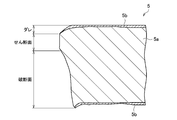
- the surface-treated work piece 5 cut using the shearing tool 10 as shown in FIG. 13 has a cut end face as shown in FIG.
- the cut end surface of the work material 5 is composed of a sagging surface, a sheared surface and a fracture surface.
- the sagging occurs when the punch 12 shown in FIG. 13 is pushed from the upper surface side to the lower surface side of the work material 5 against the work material 5 in which the surface of the metal material 5a which is the base material is coated with the coating layer 5b. , Deformation caused by the tensile force acting on the upper surface of the work piece 5.
- the sheared surface is a smooth surface formed by the movement of the punch 12 sunk into the work material 5, and the fracture surface is a surface at which the work material 5 is broken starting from a crack generated in the work material 5. is there.
- the coating layer 5b remains on the sagging portion, but hardly remains on the sheared surface, and the metal material 5a is exposed on the fracture surface.
- the corrosion resistance of the sheared surface and the fracture surface where the metal material 5a is almost exposed on the cut end surface of the work material 5 is low, and there is a concern that red rust may occur.
- a rust preventive measure for the cut end surface of a plated metal plate having a plated metal layer on the surface of a metal material sacrificial anticorrosion or chemical formation with a plated metal layer is common.
- the size of the sagging of the cut end face is within the range of 0.10 times or more of the plate thickness in the plate thickness direction and 0.45 times or more of the plate thickness in the plane direction. It is disclosed that the cutting process is performed.
- the tensile force and shearing force applied to the metal material are increased, the plated metal layer coated on the surface of the base metal material is made to wrap around the cut end face, and at least a part of the sheared surface of the cut end face is plated metal. Cover with a layer.
- the sacrificial anticorrosion action of the plated metal layer that wraps around the cut end face suppresses the occurrence of red rust on the cut end face.
- Patent Document 2 discloses a method of cutting a surface-treated steel sheet with a rotary blade shifted up and down and then treating the end face using a forming roll.
- Patent Document 3 describes a cutting method in which a V-shaped groove is formed in a steel sheet having a plating layer in the first step, and the steel sheet is cut by applying strain along the groove formed in the second step. It is disclosed.
- Patent Document 4 discloses an apparatus in which three sets of rotary blades having different heights and widths of cutting edges are arranged in a tandem shape and a strip-shaped material is gradually sheared.
- JP-A-2017-87294 Japanese Unexamined Patent Publication No. 2018-075600 Japanese Unexamined Patent Publication No. 2004-34183 JP-A-61-125718
- the plated metal layer on the surface of the base metal material only covers at least a part of the sheared surface of the cut end face, and the base metal material remains exposed in the fracture surface. Therefore, the corrosion resistance of the cut end face of the plated metal plate is not sufficient. Further, in general, when an attempt is made to impart excessive sacrificial corrosion resistance to the cut end face for the purpose of rust prevention, the plating on the surface of the plated metal plate is reduced, and the surface corrosion resistance (that is, flat corrosion resistance) on the surface of the plated metal plate is lowered. Resulting in.
- the plating coverage is increased by two processes, that is, the cutting process of the surface-treated steel sheet and the molding of the end face portion of the cut surface-treated steel sheet.
- the equipment cost increases.
- the construction method described in Patent Document 2 after cutting the surface-treated steel sheet with a rotary blade shifted up and down, the shape of the end face portion thereof is adjusted, so that stress is applied in different directions in each process. The plating layer is prone to cracking and peeling. Further, in the construction method described in Patent Document 2, it is necessary to pour more plating layers from the surface side in order to cover the end face of the steel plate which is the base material.
- Patent Document 4 a cutting device for the purpose of obtaining a strip-shaped body having a beautiful and neat side edge by cutting without causing burrs, sagging, debris peeling, etc. on the cut surface. Proposed.
- Patent Document 4 does not pay attention to the durability of the cutting edge of the annular blade. Further, in order to achieve the purpose, optimization of the cross-sectional tip radius of the cutting edge of the cutting device has not been studied.
- the cutting device includes a first annular blade portion and a second annular blade.
- the first cutting edge on the outer edge of the first annular cutting edge and the second cutting edge on the outer edge of the second annular cutting edge have a pair of cutting edges, and the radial cross-sectional shape is V-shaped.
- the work material may be a multi-layer material in which the surface of the base material is covered with a coating material.
- it may be gradually reduced tip angle theta 2 of the first cutting edge of the tip angles theta 1 and the second cutting edge in the cutting step.
- the distance S between the first blade edge and the second cutting edge in the first cutting process, the tip radius of the first cutting edge R 1, the second when the tip radius of the blade edge defined R 2, the thickness of the workpiece and t may satisfy the following equation (1). (R 1 + R 2 ) ⁇ S ⁇ ⁇ t- (R 1 + R 2 ) ⁇ ... (1)
- the shaving width of the work material is the distance between one end of the work material and the cutting position of the work material
- the shaving width D of the work material is the tip radius of the first annular blade portion R. 1
- the tip radius of the second annular edge portion R 2 when the thickness of the workpiece is defined as t, may be set so as to satisfy the following formula (2).
- R Min (R 1 , R 2 )
- Shift amount L D of the annular edge portion in the sheet passing direction is not less 1mm or more, in one cutting process, may be cut only one place workpiece.
- the distance W between adjacent blades in the plate width direction may be 200 mm or more.
- the diameter of the first annular blade portion and the second annular blade portion may be 50 mm or more.
- the present invention when cutting a work material, it is possible to suppress a decrease in the performance of the work material after cutting.
- the function can be exhibited on the cut end face while maintaining the function of the covering material on the flat surface of the base material.
- FIG. 4 It is a schematic diagram of the two roll portions of the upper rotating portion when the cutting device shown in FIG. 4 is viewed in a plan view.
- it is a front photograph of a cut end face of a plated metal material cut by a cutting device.
- it is a side sectional photograph of a cut end face of a plated metal material cut by a cutting device.
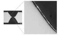
- It is an enlarged image of the cut end face of the work material of Example 3.
- It is explanatory drawing which shows an example of the conventional shearing tool. It is explanatory drawing which shows typically the cut end face of the work material cut by the shearing tool of FIG.
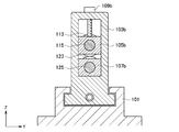
- FIG. 1 is an explanatory diagram showing an example of the cutting device 100 according to the present embodiment.
- FIG. 2 is a cross-sectional view taken along the line II of the cutting device 100 shown in FIG.
- FIG. 3 is a partially enlarged view of the upper rotating portion 110 and the lower rotating portion 120 of the cutting device 100 according to the present embodiment.
- the upper rotating portion 110 and the lower rotating portion 120 show only half of the rotation center.
- the plate width direction of the material to be processed is described as the X direction, the plate length direction as the Y direction, and the plate thickness direction as the Z direction.
- the Y direction is also the through plate direction of the work material.
- the cutting device 100 is a device that cuts the surface-treated work material 5 (see FIGS. 3 and 7) by a pair of rotating blades.
- a surface treatment material having a coating layer (coating layer 5b in FIG. 7) on the surface of a metal material (metal material 5a in FIG. 7) as a base material will be taken up.
- Examples of such a work material 5 include a plated metal plate in which the surface of the metal plate is plated, a coated metal plate in which the surface is coated on a metal material as a base material, and a film laminated on the metal plate. There are film-laminated metal plates and the like.
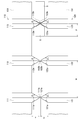
- the cutting device 100 may include a plurality of a pair of blade portions, and may include three pairs of blade portions 1, 2, and 3, as shown in FIG. 1, for example.
- the pair of blade portions 1, 2, and 3 are composed of a first annular blade portion 111, 112, 113 and a second annular blade portion 121, 122, 123, respectively.
- the paired first annular blade portion and the second annular blade portion are the tips 111b, 112b, 113b of the cutting edges 111a, 112a, 113a, 121a, 122a, 123a on the outer edge thereof.
- 121b, 122b, 123b are arranged so as to face each other.
- the radial cross-sectional shapes of the first annular blade portions 111, 112, 113 and the second annular blade portions 121, 122, 123 have a V-shape at the cutting edges 111a, 112a, 113a, 121a, 122a, 123a.
- the first annular blade portions 111, 112, 113 are supported by the first shaft portion 115 at the center of rotation.
- the second annular blade portions 121, 122, and 123 are supported by the second shaft portion 125 at the center of rotation.
- the first shaft portion 115 can be rotated via the chocks 105a and 105b
- the second shaft portion 125 can be rotated via the chocks 107a and 107b by a pair of support portions 103a and 103b at both ends, respectively. (Chock 105a and 107a are not shown).
- the pair of support portions 103a and 103b are provided on the gantry 101 in FIG.
- Sleeves 131, 133 may be provided between the support portions 103a and 103b together with the first annular blade portions 111, 112, 113 and the second annular blade portions 121, 122, 123.
- the sleeves 131 and 133 are members for adjusting the distance between the first annular blade portions 111, 112 and 113 and the distance between the second annular blade portions 121, 122 and 123.
- sleeves 131 and 133 having different widths are provided in FIG. 1, only sleeves having the same width are used, and the intervals between the first annular blade portions 111, 112, 113 and the second annular blade portions 121 are used. , 122, 123 may be adjusted.
- first annular blade portions 111, 112, 113 and the sleeves 131, 133 supported by the first shaft portion 115 are also referred to as an upper rotating portion 110.
- second annular blade portions 121, 122, 123 and the sleeves 131, 133 supported by the second shaft portion 125 are also referred to as a lower rotating portion 120.
- the upper rotating portion 110 rotates integrally with the first shaft portion 115.
- the lower rotating portion 120 rotates integrally with the second shaft portion 125.
- the pair of support portions 103a and 103b can be moved in the plate width direction (X direction) by the drive portions 104a and 104b, respectively.
- the pair of support portions 103a and 103b are screwed into the threaded portions 102a and 102b installed in parallel with the first shaft portion 115 and the second shaft portion 125.
- One end of the threaded portions 102a and 102b is connected to the driving portions 104a and 104b.
- the drive portions 104a and 104b By driving the drive portions 104a and 104b to rotate the screw portions 102a and 102b, the support portions 103a and 103b move.
- the reduction device 109a is used as an interval adjusting portion for adjusting the distance between the first annular blade portions 111, 112, 113 and the second annular blade portions 121, 122, 123, respectively.
- 109b are provided. By tightening the reduction devices 109a and 109b, the distance between the first annular blade portions 111, 112, 113 and the second annular blade portions 121, 122, 123 can be narrowed.
- the coating layer on the surface of the work material 5 penetrates into the cut end face, and the cut end face is covered with the coating layer. That is, the cutting edge 111a (112a, 113a) and the second annular blade of the first annular blade portion 111 (112, 113) with respect to the work material 5 when passing between the upper rotating portion 110 and the lower rotating portion 120.
- the coating layer on the surface of the work material 5 is made to follow the movement of the cutting edge 121a (122a, 123a) of the portion 121 (122, 123), and the coating layer is inserted into the cut end face. As a result, the cut end face of the work material 5 is covered with the coating layer.
- the cutting device according to the present embodiment is not limited to the configuration shown in FIG.
- the cutting device 100A may have a configuration in which the upper rotating portion 110A and the lower rotating portion 120A are separated into two roll portions supported by the supporting portions 103a and 103b, respectively. ..
- An annular blade portion 111 is provided on one roll portion of the upper rotating portion 110A, and an annular blade portion 113 is provided on the other roll portion.
- An annular blade portion 121 is provided on one roll portion of the lower rotating portion 120A, and an annular blade portion 123 is provided on the other roll portion. Similar to the cutting device 100 shown in FIG.
- such a cutting device 100A also causes the coating layer on the surface of the work material to follow the movements of the annular blade portions 111, 113, 121, 123 when cutting the work material. , Let the coating layer penetrate into the cut end face. As a result, the cut end face of the work material is covered with the coating layer.
- the annular blade portion 113 shown in FIG. 5 is adjusted in the installation position on the first shaft portion 115b by the sleeves 131 and 135 having different lengths in the axial direction (Y direction) of the first shaft portion 115b.
- the sleeve 131 has a longer axial length than the sleeve 135.
- the sleeve 131, the annular blade portion 113, and the sleeve 135 are provided with respect to the first shaft portion 115b in this order from the support portion 103b side.
- a stopper 137 is fastened to the tip of the first shaft portion 115b (the end opposite to the support portion 103b), and the sleeve 131, the annular blade portion 113, and the sleeve 135 are fixed to the first shaft portion 115b.
- the lower side of FIG. 5 shows the installation position of the annular blade portion 113 when the positions of the sleeve 131 and the sleeve 135 are exchanged from the state of the upper side of FIG. From FIG. 5, by adjusting the installation positions of the sleeves 131 and 135 having different lengths, the position of the annular blade portion 113 in the axial direction can be adjusted.
- a cutting device in which a plurality of annular blade portions are provided in one roll portion is a double-edged roll 1110 having two annular blade portions 1111 and 1112 at both ends in the axial direction of the shaft portion 1113, as shown in FIG. It can be configured by providing it in place of the annular blade portion 111 of the above.
- the double-edged roll 1110 is used, when one of the annular blades used for cutting the work material is worn, the double-edged roll 1110 is inverted so that the other annular blade cuts the work material. By re-installing, the work material can be continuously cut. This makes it possible to reduce the frequency of re-polishing the annular blade portion.
- FIG. 7 shows an example of the cut end face of the work piece 5 cut by the cutting device 100.
- FIG. 7 schematically shows a cross section of the side surface of the cut end surface of the work material 5 (that is, the surface viewed from the plate length direction (Y direction)).
- the cut end surface of the work piece 5 is composed of sagging s1 and s2, inclined surfaces s3 and s4, and fracture surface s5.
- the sagging s1 and the inclined surface s3 are formed by the first cutting edge of the first annular blade portion of the pair of blades, and the sagging s2 and the inclined surface s4 are formed by the second cutting edge of the second annular blade portion. Will be done.
- the fracture surface s5 is formed by breaking the work material 5 starting from a crack generated in the work material 5 by the first cutting edge and the second cutting edge.
- the work material 5 cut by the cutting device 100 according to the present embodiment is cut because the same coating layer 5b continuous at the same time as cutting covers the surface of the metal material 5a to the cut end face.
- the end face is hard to oxidize. Therefore, by cutting the work material 5 using the cutting device 100 according to the present embodiment, it is possible to provide the work material 5 having high corrosion resistance on the cut end face.
- the shape of the cut end face of the workpiece 5 cut by the cutting device 100 according to the present embodiment is due to the shapes of the first cutting edge and the second cutting edge. Since the first cutting edge and the second cutting edge have a V shape, the cut end surface of the work piece 5 has a V shape as shown in FIG. 7 instead of the vertical shear plane shown in FIG. It has a shape having inclined surfaces s3 and s4 along the slope of. Therefore, for example, the cut end face of the work piece 5 cut by the cutting device 100 of FIG. 1 has a shape that protrudes toward the center in the plate thickness direction.
- the fracture surface s5 is a surface formed by breaking the work material 5 due to cracks, it is difficult to allow the coating layer 5b to penetrate into the fracture surface s5.
- the workpiece 5 is cut along the slope until the cutting is performed in a state where the tip of the first cutting edge and the tip of the second cutting edge are substantially in contact with each other. Therefore, the fracture surface s5 has a small proportion of the fracture surface s5 in the cut end face. Therefore, even if the fracture surface s5 is not covered with the coating layer 5b, the corrosion resistance is not significantly reduced.
- the shape of the first cutting edge and the second cutting edge V-shaped like the cutting device 100 according to the present embodiment it is possible to cut a material having a tensile strength of 200 MPa or more, for example. ..
- a material having a tensile strength of 270 MPa or more and a material having a tensile strength of 590 MPa or more can be cut.
- the shift amount L D of the annular blade portion of the cutting distance W and sheet passing direction of the workpiece (Y direction) by appropriately setting, thick
- the material can also be cut, and for example, a work material having a plate thickness of 2.0 mm or more can be cut.
- the plate thickness of the material to be processed is preferably in the range of 2.0 mm or more and 9.0 mm or less, and more preferably in the range of 2.0 mm or more and 6.0 mm or less.
- the first cutting edge of the first annular blade portion and the second cutting edge of the second annular blade portion have the same V-shape as shown in FIG.
- the first cutting edge and the second cutting edge may be at least V-shaped, and preferably satisfy the following shapes, respectively.
- the shape of the cutting edge will be described focusing on the pair of blades including the first annular blade 111 and the second annular blade 121 in FIG. 3, but the other pair of blades (first). The same applies to the annular blade portion 112 and the second annular blade portion 122, the first annular blade portion 113 and the second annular blade portion 123).
- the tip angle of the cutting edge of the first annular blade portions 111, 112, 113 is ⁇ 1
- the tip radius is R 1
- the tip angle of the cutting edge of the second annular blade portions 121, 122, 123 is ⁇ 2, the tip.
- the radius will be described as R 2 .
- Tip angle theta 2 of the tip angles theta 1 and the second cutting edge 121a of the first cutting edge 111a is preferably set to 10 ° or more less than 120 °.
- the tip angles ⁇ 1 and ⁇ 2 are 10 ° or more, the inclination becomes large, so that the followability of the coating layer 5b is improved and the corrosion resistance of the cut end face is further improved. Further, the stress applied to the first cutting edge 111a and the second cutting edge 121a is reduced, damage to the cutting edge is suppressed, and the durability of the annular blade portions 111 and 112 is improved.
- the tip angle theta 2 of the tip angles theta 1 and the second cutting edge 121a of the first cutting edge 111a is set to 10 ° or more 120 ° or less, more preferably 30 ° to 90 °.
- Tip radius R 2 of the tip radius R 1 and a second cutting edge 121a of the first cutting edge 111a is preferably less 35.0% 0.5% or more the thickness t.
- the tip radii R 1 and R 2 are 0.5% or more of the plate thickness t, the stress applied to the first cutting edge 111a and the second cutting edge 121a does not become too large, and damage to the cutting edges 111a and 121a is suppressed. , Durability is improved. Further, when the tip radii R 1 and R 2 are 35.0% or less of the plate thickness t, the shape of the cut end face becomes good.
- tip radius R 2 of the tip radius R 1 and a second cutting edge 121a of the first cutting edge 111a is not more than 35.0% 0.5% or more of the plate thickness t, and more preferably a thickness of t 3 It shall be 0.0% or more and 10.0% or less.
- the first cutting edge 111a and the second cutting edge 121a may have different shapes. For example, if at least one of the tip radius R 1 and R 2 or the tip angles ⁇ 1 and ⁇ 2 is different, the first cutting edge 111a and the second cutting edge 121a have different shapes.
- the fracture surface ratio is the ratio of the fracture surface s5 to the plate thickness t of the work material 5.
- the ratio of the tip radius R 1 of the first cutting edge 111a and the tip radius R 2 of the second cutting edge 121a is preferably less than 100, more preferably It shall be less than 10.
- the most preferable case is when the tip radii R 1 and R 2 are equal.
- the ratio between the tip angle theta 2 of the tip angle theta 1 and the second cutting edge 121a of the first cutting edge 111a is preferably less than 4, more preferably 2 Less than.
- the most preferable case is when the tip angles ⁇ 1 and ⁇ 2 are equal.
- the position of the tip 111b of the first cutting edge 111a and the position of the tip 121b of the second cutting edge 121a are in the horizontal direction orthogonal to the direction in which the first annular blade portion 111 and the second annular blade portion 121 face each other. In the plate width direction (X direction), they may be matched as shown in FIG.
- the force applied to the cutting edges 111a and 121a in the X direction can be reduced and the durability is improved. ..
- cracks can be generated from the cutting edge at an appropriate timing to complete cutting.
- the position of the tip 111b of the first cutting edge 111a and the position of the tip 121b of the second cutting edge 121a may be displaced by the amount x in the horizontal direction.
- the deviation amount x of the tip position means the distance between the tip 111b of the first cutting edge 111a and the tip 121b of the second cutting edge 121a in the horizontal direction (plate width direction, X direction).
- the amount of deviation of the tip position is preferably 50% or less of the plate thickness t. When the amount of deviation of the tip position is 50% or less of the plate thickness t, the work piece 5 can be cut so as to surely obtain the desired end surface properties.
- first annular blade portion 111 and the second annular blade portion 121 of the pair of blade portions may be arranged symmetrically with respect to the work material.
- the cutting width D of the work material 5 refers to the length at which the work material 5 should be left in the plate length direction (X direction) from the cutting position at the time of cutting by the cutting device 100.
- the cutting width D of the work material 5 is represented by the length from the cutting position to one end of the work material 5, for example, as shown in FIG.
- the cutting width D of the work material 5 is, for example, the work material 5.
- the length may be the length from the end to the tip position of the blade on the side closer to the end.
- the cutting width D of the work material 5 is equal to or more than the tip radius R of the annular blade portion and is 5 times or less (R ⁇ D ⁇ 5 t) of the plate thickness t of the work material 5, especially the plate thickness t of the work material 5. It is preferably 3 times or less of (R ⁇ D ⁇ 3t). More preferably, the cutting width D of the work material 5 is three times or more the tip radius R of the annular blade portion and is not more than the plate thickness t of the work material 5 (3R ⁇ D ⁇ t).
- the tip radius R of the annular blade portion is a tip radius R 2 of the first annular edge 111, 112, 113 tip radius R 1 or second annular blade portion 121, 122 and 123.
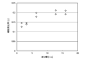
- FIG. 8 shows an example of the relationship between the cutting width D and the fracture surface ratio.
- a galvanized steel sheet having a plate thickness of 3.2 mm and a tensile strength of 460 MPa was used as the work material 5.
- the tip radius R of the cutting device 100 was 0.05 mm, and the tip angle ⁇ was 60 °.
- the two plots at the same cutting width D show the fracture surface ratios measured for the two pieces of work piece 5 cut by the cutting device 100.
- the shapes of the first annular blade portions 111, 112, 113 and the second annular blade portions 121, 122, 123, the first annular blade portions 111, 112, 113 and the second annular blade portions 121 By changing the amount of deviation of the tip positions from 122 and 123 or the cutting width D of the work material 5, the shape of the cut end face of the work material 5 cut by the cutting device 100 changes, and the shape of the cut end face of the cut end face changes.
- the coating state of the coating layer 5b changes.
- the shapes of the first annular blade portions 111, 112, 113 and the second annular blade portions 121, 122, 123, the first annular blade portions 111, 112, 113 and the second annular blade portions 121, 122, The amount of deviation of the tip position from 123 and the cutting width D of the work material 5 may be appropriately set according to the shape of the cut end face or the corrosion resistance required for the work material 5 after cutting.
- first annular blade portions 111, 112, 113 and the second annular blade portions 121, 122, 123 may have different V-shapes to improve the flatness of the cut end face.
- the roll diameters of the annular blade portion 111 of 1 and the second annular blade portion 121 are 50 mm or more, preferably 400 mm or more. The larger the roll diameter, the more difficult it is for the plating to be extruded in the plate-passing direction of the work material 5 during cutting, so that the amount of plating coating on the inclined surface can be increased.
- the upper limit of the roll system is not particularly limited, but may be 3000 mm in consideration of the size of the cutting device 100 or the work piece 5.
- the cutting distance W which is the distance between the blades adjacent to each other in the plate width direction (X direction), is preferably 200 mm or more. It shall be 500 mm or more. If the cutting distance W is 200 mm or more, even if two or more cut points are cut in one cutting step, the cut points of the work material 5 are sufficiently separated from each other, so that there is no escape place for the material. It is possible to eliminate the breakage defect due to.
- the upper limit of the cutting distance W is not particularly limited, but may be 10000 mm in consideration of the size of the cutting device 100 or the work piece 5.
- the workpiece 5 when the distance W between cuttings cannot be sufficiently secured, it is preferable to cut the workpiece 5 at only one place in one cutting step. If the material 5 to be processed is cut at two or more places in one cutting step, the material cannot escape due to the pushing of the cutting edge. That is, a pressure stress field is formed between the blades, and the work piece 5 is less likely to break. Therefore, by shifting the annular blade portion adjacent to the plate width direction (X direction) in the plate passing direction (Y direction), it is possible to prevent cutting at two or more locations in one cutting process. Therefore, the work piece 5 can be reliably cut.
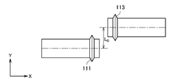
- FIG. 9 shows a schematic view of the two roll portions of the upper rotating portion 110A of the cutting device 100A shown in FIG. 4 in a plan view.
- the amount of deviation LD is preferably 1 mm or more, more preferably 4 mm or more.
- the height h 2 of the heights h 1 and the second cutting edge 121a of the first cutting edge 111a is at least the sum of these (h 1 + h 2) may be larger than the thickness t of the workpiece 5.
- the material 5 to be processed by the cutting device 100 may be cut by one cutting step or by a plurality of cutting steps.
- Cutting by a plurality of cutting steps means cutting the work piece 5 into two pieces by performing a cutting step of passing the work material 5 between a pair of blades a plurality of times.
- the pair of blades 1 performs the first cutting step
- the pair of blades 2 performs the second cutting step
- the pair of blades 3 performs the third cutting.
- a plurality of cutting steps may be carried out, such as carrying out the steps.
- a plurality of cutting devices may be installed in the plate-through direction of the material to be processed so that a plurality of cutting steps can be performed by one plate-passing. By installing the cutting device in a tandem shape in this way, a plurality of cutting steps can be efficiently performed.
- various cut end faces can be realized. For example, when cutting the workpiece 5 by a plurality of cutting process, so as to gradually reduce the tip angle theta 2 of the tip angles theta 1 and the second cutting edge 121a of the first cutting edge 111a at the cutting step May be good. As a result, the portion covered by the coating layer 5b on the cut end face can be increased, and a good end face shape can be obtained.
- the distance between the first annular blade portion 111 and the second annular blade portion 121 in each cutting process should be gradually reduced.
- the coating layer 5b can follow the movements of the first cutting edge 111a and the second cutting edge 121a. Increase.
- the distance S between the first annular blade portion 111 and the second annular blade portion 121 in the first cutting step is the following formula (1). It is preferable to satisfy the relational expression of. More preferably, the distance S between the first annular blade portion 111 and the second annular blade portion 121 in the first cutting step satisfies the following formula (1-2).
- the first step in each cutting step is performed. may be gradually increased tip angle theta 2 of the tip angles theta 1 and the second cutting edge 121a of the cutting edge 111a.
- FIG. 10 shows a front photograph of the cut end face of the plated metal material cut by the cutting device.
- FIG. 11 shows a side sectional photograph of the cut end face of the plated metal material cut by the cutting device.
- FIGS. 10 and 11 as Examples 1 to 3, a front photograph and a side cross-sectional photograph of the cut end face of the plated metal material when the plated metal material is cut by the cutting device 100 of the present invention shown in FIG. Is shown.
- Pieces A and B in FIG. 10 show two pieces of plated metal material separated by cutting with a cutting device.
- FIG. 11 is a frontal photograph of the piece A and the piece B shown in FIG. 10 at the center position in the longitudinal direction.
- the tip radii R 1 and R 2 of the cutting edge are different, but the cut end face is formed by sagging, an inclined surface and a fracture surface, and the inclined surface is formed.
- the ratio was large.
- Plating remained on the inclined surface, and the amount of plating covering the inclined surface decreased from the surface of the metal material toward the center of the plate thickness.
- the tip radii R 1 and R 2 of the cutting edge are larger than those in Example 1
- the reduction rate of the amount of plating from the surface of the metal material to the vicinity of the center of the plate thickness on the inclined surface is small and more.
- the plating of was following. For example, FIG.
- FIG. 12 shows an enlarged image of the cut end face of the work material of Example 3. As shown in FIG. 12, it can be seen that the inclined surface of the work material is coated with a coating layer on the surface of the metal material. In this way, by cutting the plated metal material using the cutting device of the present invention, it is possible to cover the cut end face by plating over a wide range.
- the material to be processed is a plated steel sheet, but the present invention is not limited to such an example.
- the work material may be formed by covering the surface of the base material with a coating material.
- a metal material such as a steel plate may be used as a base material, and a material made of Zn, Al or an alloy thereof, an oxide film, a coating material, a resin material or the like may be used as a coating material.
- the work material may be a coated steel sheet whose surface is coated on a metal material as a base material, or a film-laminated steel sheet in which a film is laminated on the steel sheet.
- the cut product can be produced from a clad material composed of a base material and a coating material.
- the clad material include a Ni clad copper material having a Cu plate as a base material and a Ni plate as a coating material.
- the material to be processed is not limited to only one layer, and may be coated with a plurality of layers.
- the surface of the above-mentioned plated steel sheet may be subjected to chemical conversion treatment, painting, laminating or the like.
- a processed material obtained by using a resin material such as plastic as a base material and a metal material such as Cu, Cr, Ag, Au, Pt as a coating material is also cut in the same manner. Can be formed.
- the purpose required when cutting is different depending on the combination with the material to be processed and the application.
- the corrosion resistance, chemical resistance, and the like of the base material of the cut end face can be improved.
- the electrical conductivity, thermal conductivity, magnetism, etc. of a part or the whole of the cut end face can be improved as compared with the conventional cutting method.
- the cutting method according to the present embodiment it is possible to prevent the performance of the work material from being deteriorated after cutting in the cutting of the work material. This applies not only to cutting the surface-treated work material, but also to cutting the bare material. For example, by using the cutting method according to the present embodiment, it is possible to suppress a decrease in the fatigue life of the cut work material regardless of the presence or absence of the covering material.
- the cutting device may cut the material to be processed in a curved shape, and may cut into an arbitrary shape such as a circular shape.
- a cutting method for cutting a work material that has been surface-treated using a cutting device has a pair of blades including a first annular blade and a second annular blade.
- the first cutting edge on the outer edge of the first annular blade and the second cutting edge on the outer edge of the second annular blade have a V-shaped radial cross section.
- the first annular blade portion and the second annular blade portion are arranged so that the tip position of the first cutting edge and the tip position of the second cutting edge coincide with each other (1).
- the cutting width of the work material is the distance between one end of the work material and the cutting position of the work material.
- the cutting width D of the work material is defined as R 1 for the tip radius of the first annular blade portion, R 2 for the tip radius of the second annular blade portion, and t for the plate thickness of the work material.
- the cutting method described in the section. (13) The cutting method according to (12) above, wherein when the cutting device is provided with a plurality of the pair of blades, the distance W between the blades adjacent to each other in the plate width direction is 500 mm or more. (14) The cutting method according to any one of (1) to (13) above, wherein the diameter of the first annular blade portion and the second annular blade portion is 50 mm or more. (15) The cutting method according to (14) above, wherein the diameter of the first annular blade portion and the second annular blade portion is 400 mm or more. (16) The above (1) to (15), wherein the rotation speed of the first annular blade portion and the rotation speed of the second annular blade portion are set to a speed different from the transfer speed of the work material.
- a support portion that rotatably supports both ends of the first shaft portion and the second shaft portion, and An interval adjusting portion for adjusting the distance between the first annular blade portion and the second annular blade portion, With The first cutting edge on the outer edge of the first annular blade and the second cutting edge on the outer edge of the second annular blade face each other and each has a V-shaped radial cross section.
- a cutting device in which the distance between the first annular blade portion and the second annular blade portion is adjusted by the spacing adjusting portion according to the plate thickness of the work material.
Landscapes
- Chemical & Material Sciences (AREA)
- Engineering & Computer Science (AREA)
- Mechanical Engineering (AREA)
- Chemical Kinetics & Catalysis (AREA)
- Materials Engineering (AREA)
- Metallurgy (AREA)
- Organic Chemistry (AREA)
- Finish Polishing, Edge Sharpening, And Grinding By Specific Grinding Devices (AREA)
- Shearing Machines (AREA)
- Milling Processes (AREA)
Abstract
Description
(R1+R2)≦S≦{t-(R1+R2)} ・・・(1)
R≦D≦3t ・・・(2)
R=Min(R1,R2)
まず、図1~図3に基づいて、本発明の一実施形態に係る切断装置100の概略構成について説明する。なお、図1は、本実施形態に係る切断装置100の一例を示す説明図である。図2は、図1に示す切断装置100のI-I切断線における断面図である。図3は、本実施形態に係る切断装置100の上回転部110及び下回転部120の部分拡大図である。図3では、上回転部110及び下回転部120は、回転中心から半分のみをそれぞれ示している。図1~図3では、被加工材の板幅方向をX方向、板長方向をY方向、板厚方向をZ方向として説明する。Y方向は、被加工材の通板方向でもある。
切断装置100により切断された被加工材5の切断端面の一例を図7に示す。図7では、被加工材5の切断端面の側面(すなわち、板長方向(Y方向)から見た面)の断面を模式的に示している。図7に示すように、被加工材5の切断端面は、ダレs1、s2と、傾斜面s3、s4と、破断面s5とからなる。ダレs1及び傾斜面s3は、一対の刃部のうち第1の環状刃部の第1の刃先により形成され、ダレs2及び傾斜面s4は、第2の環状刃部の第2の刃先により形成される。破断面s5は、第1の刃先及び第2の刃先によって被加工材5に生じたクラックが起点となって被加工材5が破断して形成される。
本実施形態に係る切断装置100において、第1の環状刃部の第1の刃先と第2の環状刃部の第2の刃先とは、図3に示すように同一のV字形状を有する。しかし、第1の刃先及び第2の刃先は、少なくともV字形状であればよく、それぞれ以下の形状を満たしていることが好ましい。以下では、図3の第1の環状刃部111と第2の環状刃部121とからなる一対の刃部に着目して刃先の形状を説明するが、他の一対の刃部(第1の環状刃部112と第2の環状刃部122、第1の環状刃部113と第2の環状刃部123)も同様とする。また、第1の環状刃部111、112、113の刃先の先端角度をθ1、先端半径をR1とし、第2の環状刃部121、122、123の刃先の先端角度をθ2、先端半径をR2として説明する。
第1の刃先111aの先端角度θ1及び第2の刃先121aの先端角度θ2は、10°以上120°以下とすることが好ましい。先端角度θ1、θ2が10°以上であると、傾斜が大きくなるため、被膜層5bの追従性が向上し、切断端面の耐食性がより向上する。また、第1の刃先111a及び第2の刃先121aにかかる応力が小さくなり、刃先の損傷が抑制され、環状刃部111、112の耐久性が向上する。また、先端角度θ1、θ2が120°以下であると、被加工材5を切断するために必要な荷重が大きくなり過ぎず、かつ、刃先111a、121aを押し込んだ場合に被加工材5に亀裂が生じやすくなるので、被加工材5の切断が容易になる。このため、第1の刃先111aの先端角度θ1及び第2の刃先121aの先端角度θ2は、10°以上120°以下とし、より好ましくは30°以上90°以下とする。
第1の刃先111aの先端半径R1及び第2の刃先121aの先端半径R2は、板厚tの0.5%以上35.0%以下とすることが好ましい。先端半径R1、R2が板厚tの0.5%以上であると、第1の刃先111a及び第2の刃先121aにかかる応力が大きくなり過ぎず、刃先111a、121aの損傷が抑制され、耐久性が向上する。また、先端半径R1、R2が板厚tの35.0%以下であると、切断端面の形状が良好となる。また、刃先111a、121aを押し込んだ場合に被加工材5に亀裂が生じやすくなるので、被加工材5の切断がより容易になる。このため、第1の刃先111aの先端半径R1及び第2の刃先121aの先端半径R2は、板厚tの0.5%以上35.0%以下とし、より好ましくは板厚tの3.0%以上10.0%以下とする。
第1の刃先111aの先端111bの位置と第2の刃先121aの先端121bの位置とは、第1の環状刃部111と第2の環状刃部121とが対向する方向に直交する水平方向(板幅方向、X方向)において、図3に示すように一致させてもよい。第1の刃先111aの先端111bの位置と第2の刃先121aの先端121bの位置とを一致させることで、刃先111a、121aにかかるX方向の力を低減させることができ、耐久性が向上する。また、適切なタイミングで刃先から亀裂を発生させ、切断を完了させることができる。
被加工材5の削り幅Dは、切断装置100による切断時に切断位置から板長方向(X方向)に被加工材5を残しておくべき長さをいう。被加工材5の削り幅Dは、例えば図3に示すように、切断位置から被加工材5の一方の端部までの長さで表される。第1の環状刃部113の刃先113aの位置と第2の環状刃部123の刃先123aの位置とがずれている場合には、被加工材5の削り幅Dは、例えば被加工材5の端部から当該端部に近い側の刃部の先端位置までの長さとすればよい。
第1の環状刃部111と第2の環状刃部121とは、それぞれロール径(直径)が大きいほど、被加工材5の切断端面を被膜層5bにより被覆させることができる。1の環状刃部111及び第2の環状刃部121のロール径は、50mm以上であり、好ましくは400mm以上である。ロール径が大きいほど切断の際にめっきが被加工材5の通板方向に押し出されにくくなるため、傾斜面のめっき被覆量を増加させることができる。なお、ロール系の上限は特に限定されないが、切断装置100または被加工材5の大きさを勘案すると、3000mmであってもよい。
図3に示すように、切断装置100に一対の刃部が複数設けられている場合、板幅方向(X方向)に隣接する刃部の間隔である切断間距離Wは200mm以上とし、好ましくは500mm以上とする。切断間距離Wを200mm以上とすれば、1回の切断工程で2箇所以上切断された場合にも、被加工材5の切断箇所の間隔が十分に離れているため、材料の逃げ場がなくなることによる破断不良を解消することができる。なお、切断間距離Wの上限は特に限定されないが、切断装置100または被加工材5の大きさを勘案すると、10000mmであってもよい。
第1の刃先111aの高さh1及び第2の刃先121aの高さh2は、少なくともこれらの和(h1+h2)が被加工材5の板厚tよりも大きくすればよい。
(R1+R2)×2≦S≦{t-(R1+R2)×2} ・・・(1-2)
(1) 切断装置を用いて表面処理が施された被加工材を切断する切断方法であって、
前記切断装置は、
第1の環状刃部と第2の環状刃部とからなる一対の刃部を有し、
前記第1の環状刃部の外縁にある第1の刃先及び前記第2の環状刃部の外縁にある第2の刃先は、径方向断面形状がV字形状であり、
対向する前記第1の刃先と前記第2の刃先との間に前記被加工材を通板させて、前記被加工材に刃先を押し込み、前記被加工材を切断する、切断方法。
(2) 前記第1の環状刃部と前記第2の環状刃部とは、前記第1の刃先の先端位置と前記第2の刃先の先端位置とが一致して配置される、上記(1)に記載の切断方法。
(3) 前記第1の環状刃部の前記第1の刃先と前記第2の環状刃部の前記第2の刃先とを対向させたとき、前記第1の刃先の先端位置と前記第2の刃先の先端位置とのずれ量を板厚の50%以下とする、上記(1)に記載の切断方法。
(4) 前記第1の環状刃部の前記第1の刃先及び前記第2の環状刃部の前記第2の刃先は、同一形状であり、前記被加工材に対して対称に配置される、上記(1)~(3)のいずれか1項に記載の切断方法。
(5) 前記被加工材の切断は、複数の切断工程で行われる、上記(1)~(4)のいずれか1項に記載の切断方法。
(6) 前記複数の切断工程による前記被加工材の切断では、各切断工程での前記第1の刃先の先端角度θ1及び前記第2の刃先の先端角度θ2を徐々に小さくする、上記(5)に記載の切断方法。
(7) 前記被加工材が2回の切断工程により切断されるとき、1回目の切断工程における前記第1の刃先と前記第2の刃先との間隔Sは、前記第1の刃先の先端半径をR1、前記第2の刃先の先端半径をR2、前記被加工材の板厚をtと定義したとき、下記式(a)を満たす、上記(5)または(6)に記載の切断方法。
(R1+R2)≦S≦{t-(R1+R2)} ・・・(a)
(8) 前記被加工材が2回の切断工程により切断されるとき、1回目の切断工程における前記第1の刃先と前記第2の刃先との間隔Sは、下記式(b)を満たす、上記(7)に記載の切断方法。
(R1+R2)×2≦S≦{t-(R1+R2)×2} ・・・(b)
(9) 前記被加工材の削り幅は、前記被加工材の一方の端部と当該被加工材の切断位置との距離であり、
前記被加工材の削り幅Dは、前記第1の環状刃部の先端半径をR1、前記第2の環状刃部の先端半径をR2、前記被加工材の板厚をtと定義したとき、下記式(c)を満たす、上記(1)~(8)のいずれか1項に記載の切断方法。
R≦D≦5t ・・・(c)
R=Min(R1,R2)
(10) 前記被加工材の削り幅Dは、下記式(d)を満たす、上記(9)に記載の切断方法。
3R≦D≦t ・・・(d)
(11) 1回の切断工程では、前記被加工材を1箇所のみ切断する、上記(1)~(10)のいずれか1項に記載の切断方法。
(12) 前記切断装置に前記一対の刃部が複数設けられている場合、板幅方向に隣接する前記刃部の間隔Wは200mm以上とする、上記(1)~(11)のいずれか1項に記載の切断方法。
(13) 前記切断装置に前記一対の刃部が複数設けられている場合、板幅方向に隣接する前記刃部の間隔Wは500mm以上とする、上記(12)に記載の切断方法。
(14) 前記第1の環状刃部及び前記第2の環状刃部の直径は、50mm以上である、上記(1)~(13)のいずれか1項に記載の切断方法。
(15) 前記第1の環状刃部及び前記第2の環状刃部の直径は、400mm以上である、上記(14)に記載の切断方法。
(16) 前記第1の環状刃部の回転速度及び前記第2の環状刃部の回転速度は、前記被加工材の搬送速度と異なる速度に設定される、上記(1)~(15)のいずれか1項に記載の切断方法。
(17) 前記被加工材は、引張強度270MPa以上の材料である、上記(1)~(16)のいずれか1項に記載の切断方法。
(18) 前記被加工材は、引張強度590MPa以上の材料である、上記(17)に記載の切断方法。
(19) 前記被加工材は、めっき金属板である、上記(1)~(18)のいずれか1項に記載の切断方法。
(20) 第1の環状刃部と第2の環状刃部とからなる一対の刃部と、
前記第1の環状刃部を支持する第1の軸部、及び、前記第2の環状刃部を支持する第2の軸部と、
前記第1の軸部及び前記第2の軸部の両端をそれぞれ回転可能に支持する支持部と、
前記第1の環状刃部と前記第2の環状刃部との間隔を調整する間隔調整部と、
を備え、
前記第1の環状刃部の外縁にある第1の刃先及び前記第2の環状刃部の外縁にある第2の刃先は、対向し、それぞれ径方向断面形状がV字形状であり、
被加工材の板厚に応じて、前記間隔調整部により前記第1の環状刃部と前記第2の環状刃部との間隔が調整される、切断装置。
5 被加工材
5a 金属材
5b 被膜層
100 切断装置
101 架台
103a、103b 支持部
104a、104b 駆動部
105a、105b、107a、107b チョック
109a、109b 圧下装置
110 上回転部
111、112、113 第1の環状刃部
111a、112a、113a 第1の刃先
111b、112b、113b 先端
115 第1の軸部
120 下回転部
121、122、123 第2の環状刃部
121a、122a、123a 第2の刃先
121b、122b、123b 先端
125 第2の軸部
131、133 スリーブ
1110 両刃ロール
Claims (9)
- 切断装置を用いて被加工材を切断する切断方法であって、
前記切断装置は、
第1の環状刃部と第2の環状刃部とからなる一対の刃部を有し、
前記第1の環状刃部の外縁にある第1の刃先及び前記第2の環状刃部の外縁にある第2の刃先は、径方向断面形状がV字形状であり、
前記第1の刃先の先端角度θ1及び前記第2の刃先の先端角度θ2は、10°以上120°以下であり、
前記第1の刃先の先端半径R1及び前記第2の刃先の先端半径R2は、板厚の0.5%以上35.0%以下であり、
対向する前記第1の刃先と前記第2の刃先との間に前記被加工材を通板させて、前記被加工材に刃先を押し込み、前記被加工材を切断する、切断方法。 - 前記被加工材は、母材の表面を被覆材により被覆してなる複層材である、請求項1に記載の切断方法。
- 前記被加工材の切断は、複数の切断工程で行われる、請求項1または2に記載の切断方法。
- 前記複数の切断工程による前記被加工材の切断では、各切断工程での前記第1の刃先の先端角度θ1及び前記第2の刃先の先端角度θ2を徐々に小さくする、請求項3に記載の切断方法。
- 前記被加工材が2回の切断工程により切断されるとき、1回目の切断工程における前記第1の刃先と前記第2の刃先との間隔Sは、前記第1の刃先の先端半径をR1、前記第2の刃先の先端半径をR2、前記被加工材の板厚をtと定義したとき、下記式(1)を満たす、請求項3または4に記載の切断方法。
(R1+R2)≦S≦{t-(R1+R2)} ・・・(1) - 前記被加工材の削り幅は、前記被加工材の一方の端部と当該被加工材の切断位置との距離であり、
前記被加工材の削り幅Dは、前記第1の環状刃部の先端半径をR1、前記第2の環状刃部の先端半径をR2、前記被加工材の板厚をtと定義したとき、下記式(2)を満たす、請求項1~5のいずれか1項に記載の切断方法。
R≦D≦3t ・・・(2)
R=Min(R1,R2) - 通板方向における環状刃部のずれ量LDが1mm以上であり、
1回の切断工程では、前記被加工材を1箇所のみ切断する、請求項1~6のいずれか1項に記載の切断方法。 - 前記切断装置に前記一対の刃部が複数設けられている場合、板幅方向に隣接する前記刃部の間隔Wは200mm以上とする、請求項1~7のいずれか1項に記載の切断方法。
- 前記第1の環状刃部及び前記第2の環状刃部の直径は、50mm以上である、請求項1~8のいずれか1項に記載の切断方法。
Priority Applications (5)
| Application Number | Priority Date | Filing Date | Title |
|---|---|---|---|
| SG11202109802T SG11202109802TA (en) | 2019-03-12 | 2020-01-09 | Cutting method |
| KR1020217032058A KR102758451B1 (ko) | 2019-03-12 | 2020-01-09 | 절단 방법 |
| CN202080020242.0A CN113557099B (zh) | 2019-03-12 | 2020-01-09 | 切断方法 |
| PH1/2021/552127A PH12021552127A1 (en) | 2019-03-12 | 2020-01-09 | Cutting method |
| JP2021505542A JP7299524B2 (ja) | 2019-03-12 | 2020-01-09 | 切断方法 |
Applications Claiming Priority (2)
| Application Number | Priority Date | Filing Date | Title |
|---|---|---|---|
| JP2019-044630 | 2019-03-12 | ||
| JP2019044630 | 2019-03-12 |
Publications (1)
| Publication Number | Publication Date |
|---|---|
| WO2020183883A1 true WO2020183883A1 (ja) | 2020-09-17 |
Family
ID=72427016
Family Applications (1)
| Application Number | Title | Priority Date | Filing Date |
|---|---|---|---|
| PCT/JP2020/000527 Ceased WO2020183883A1 (ja) | 2019-03-12 | 2020-01-09 | 切断方法 |
Country Status (6)
| Country | Link |
|---|---|
| JP (1) | JP7299524B2 (ja) |
| KR (1) | KR102758451B1 (ja) |
| CN (1) | CN113557099B (ja) |
| PH (1) | PH12021552127A1 (ja) |
| SG (1) | SG11202109802TA (ja) |
| WO (1) | WO2020183883A1 (ja) |
Cited By (1)
| Publication number | Priority date | Publication date | Assignee | Title |
|---|---|---|---|---|
| WO2024189948A1 (ja) | 2023-03-16 | 2024-09-19 | 日本製鉄株式会社 | 電縫鋼管の製造方法及び電縫鋼管 |
Families Citing this family (1)
| Publication number | Priority date | Publication date | Assignee | Title |
|---|---|---|---|---|
| KR20250098400A (ko) | 2023-12-22 | 2025-07-01 | 양영수 | 스프링을 활용한 충격완화 드론공 |
Citations (5)
| Publication number | Priority date | Publication date | Assignee | Title |
|---|---|---|---|---|
| JPS55120459A (en) * | 1979-03-12 | 1980-09-16 | Nippon Steel Corp | Longitudinal cutting method of slab and device thereof |
| JPS5722857A (en) * | 1980-07-15 | 1982-02-05 | Kawasaki Steel Corp | Hot cutting method for continuously cast ingot |
| JPS57106459A (en) * | 1980-12-22 | 1982-07-02 | Kawasaki Steel Corp | Cutter for ingot |
| JPS61125719A (ja) * | 1984-11-22 | 1986-06-13 | Oiles Ind Co Ltd | 軸受の基礎材となる巾の狭い小帯状材を製造する方法 |
| JP2004034183A (ja) * | 2002-07-01 | 2004-02-05 | Denki Shizai Kk | 鋼板の切断方法及び切断した鋼板 |
Family Cites Families (10)
| Publication number | Priority date | Publication date | Assignee | Title |
|---|---|---|---|---|
| JPS61125718A (ja) * | 1984-11-22 | 1986-06-13 | Oiles Ind Co Ltd | 帯状材の切断方法及び装置 |
| JP3980248B2 (ja) | 2000-05-17 | 2007-09-26 | 富士フイルム株式会社 | 金属板加工装置及び金属板加工方法 |
| JP4704546B2 (ja) | 2000-05-29 | 2011-06-15 | パナソニック株式会社 | 電池電極板用スリッター装置 |
| US20050217447A1 (en) | 2004-03-31 | 2005-10-06 | R. J. Reynolds Tobacco Company | Slitter device with adjustable blade |
| CN102712046B (zh) * | 2010-01-29 | 2014-05-21 | 京瓷株式会社 | 切削镶刀及切削工具、以及使用该切削工具的被切削件的切削方法 |
| JP5595815B2 (ja) | 2010-07-13 | 2014-09-24 | 東洋刃物株式会社 | スリッタ装置 |
| JP2015085430A (ja) * | 2013-10-30 | 2015-05-07 | 京セラ株式会社 | スリッティング工具用切断刃およびスリッティング工具 |
| JP6237894B2 (ja) * | 2014-05-08 | 2017-11-29 | 新日鐵住金株式会社 | せん断加工部品の製造方法及び製造装置 |
| JP6073025B1 (ja) | 2015-11-04 | 2017-02-01 | 日新製鋼株式会社 | 切断端面を有する表面処理鋼板の部品およびその切断加工方法 |
| JP2018075600A (ja) | 2016-11-09 | 2018-05-17 | 日新製鋼株式会社 | 表面処理鋼板の端面の構成、表面処理鋼板の部材、および表面処理鋼板の部材の製造方法 |
-
2020
- 2020-01-09 SG SG11202109802T patent/SG11202109802TA/en unknown
- 2020-01-09 KR KR1020217032058A patent/KR102758451B1/ko active Active
- 2020-01-09 CN CN202080020242.0A patent/CN113557099B/zh active Active
- 2020-01-09 WO PCT/JP2020/000527 patent/WO2020183883A1/ja not_active Ceased
- 2020-01-09 PH PH1/2021/552127A patent/PH12021552127A1/en unknown
- 2020-01-09 JP JP2021505542A patent/JP7299524B2/ja active Active
Patent Citations (5)
| Publication number | Priority date | Publication date | Assignee | Title |
|---|---|---|---|---|
| JPS55120459A (en) * | 1979-03-12 | 1980-09-16 | Nippon Steel Corp | Longitudinal cutting method of slab and device thereof |
| JPS5722857A (en) * | 1980-07-15 | 1982-02-05 | Kawasaki Steel Corp | Hot cutting method for continuously cast ingot |
| JPS57106459A (en) * | 1980-12-22 | 1982-07-02 | Kawasaki Steel Corp | Cutter for ingot |
| JPS61125719A (ja) * | 1984-11-22 | 1986-06-13 | Oiles Ind Co Ltd | 軸受の基礎材となる巾の狭い小帯状材を製造する方法 |
| JP2004034183A (ja) * | 2002-07-01 | 2004-02-05 | Denki Shizai Kk | 鋼板の切断方法及び切断した鋼板 |
Cited By (2)
| Publication number | Priority date | Publication date | Assignee | Title |
|---|---|---|---|---|
| WO2024189948A1 (ja) | 2023-03-16 | 2024-09-19 | 日本製鉄株式会社 | 電縫鋼管の製造方法及び電縫鋼管 |
| KR20250156763A (ko) | 2023-03-16 | 2025-11-03 | 닛폰세이테츠 가부시키가이샤 | 전봉 강관의 제조 방법 및 전봉 강관 |
Also Published As
| Publication number | Publication date |
|---|---|
| CN113557099B (zh) | 2024-10-29 |
| SG11202109802TA (en) | 2021-10-28 |
| JPWO2020183883A1 (ja) | 2020-09-17 |
| CN113557099A (zh) | 2021-10-26 |
| JP7299524B2 (ja) | 2023-06-28 |
| KR102758451B1 (ko) | 2025-01-23 |
| KR20210136073A (ko) | 2021-11-16 |
| PH12021552127A1 (en) | 2022-08-15 |
Similar Documents
| Publication | Publication Date | Title |
|---|---|---|
| JP7328576B2 (ja) | 切断方法及び切断加工品 | |
| JP7596060B2 (ja) | 切断加工品 | |
| JP2018075600A (ja) | 表面処理鋼板の端面の構成、表面処理鋼板の部材、および表面処理鋼板の部材の製造方法 | |
| US5152047A (en) | Method of producing laminated metal belt | |
| WO2020183883A1 (ja) | 切断方法 | |
| JP7801555B2 (ja) | せん断加工装置及びせん断加工装置を用いた加工材の製造方法 | |
| CN102615334B (zh) | 一种钢板切边的前处理方法及装置 | |
| JPH09277113A (ja) | 金属帯板の条切り装置および条切り方法 | |
| JP7248890B2 (ja) | 表面処理金属部材の製造方法 | |
| JP7155784B2 (ja) | 表面処理鋼板の切断方法 | |
| JP7135767B2 (ja) | 表面処理鋼板の切断方法 | |
| CN108672526A (zh) | 一种卷板设备及自动化卷板工艺 | |
| JP7248891B2 (ja) | 表面処理金属部材の製造方法 | |
| EP4414111A1 (en) | Cutting device and multi-layer material | |
| WO2025099960A1 (ja) | 切断装置、切断方法及び複層材 | |
| WO2023127479A1 (ja) | 加工装置、金属製部材の製造方法、及び金属製部材 | |
| TWI921203B (zh) | 切斷裝置及多層材 | |
| WO2023148899A1 (ja) | 鋼材、自動車部品、せん断加工装置及び鋼材の製造方法 | |
| JP5764192B2 (ja) | 電着ドラム | |
| HK40105792A (zh) | 切割装置和多层材料 | |
| JP4692350B2 (ja) | 鋼板の端面機械加工方法及び装置 | |
| CN114559088A (zh) | 一种钢塑复合打包带加工的圆盘剪刀及其使用方法 |
Legal Events
| Date | Code | Title | Description |
|---|---|---|---|
| 121 | Ep: the epo has been informed by wipo that ep was designated in this application |
Ref document number: 20768955 Country of ref document: EP Kind code of ref document: A1 |
|
| ENP | Entry into the national phase |
Ref document number: 2021505542 Country of ref document: JP Kind code of ref document: A |
|
| NENP | Non-entry into the national phase |
Ref country code: DE |
|
| ENP | Entry into the national phase |
Ref document number: 20217032058 Country of ref document: KR Kind code of ref document: A |
|
| 122 | Ep: pct application non-entry in european phase |
Ref document number: 20768955 Country of ref document: EP Kind code of ref document: A1 |