WO2020179936A1 - 導光板の製造方法、導光板および車両用灯具 - Google Patents
導光板の製造方法、導光板および車両用灯具 Download PDFInfo
- Publication number
- WO2020179936A1 WO2020179936A1 PCT/JP2020/010107 JP2020010107W WO2020179936A1 WO 2020179936 A1 WO2020179936 A1 WO 2020179936A1 JP 2020010107 W JP2020010107 W JP 2020010107W WO 2020179936 A1 WO2020179936 A1 WO 2020179936A1
- Authority
- WO
- WIPO (PCT)
- Prior art keywords
- guide plate
- light guide
- optical path
- light
- region
- Prior art date
- Legal status (The legal status is an assumption and is not a legal conclusion. Google has not performed a legal analysis and makes no representation as to the accuracy of the status listed.)
- Ceased
Links
Images



Classifications
-
- F—MECHANICAL ENGINEERING; LIGHTING; HEATING; WEAPONS; BLASTING
- F21—LIGHTING
- F21S—NON-PORTABLE LIGHTING DEVICES; SYSTEMS THEREOF; VEHICLE LIGHTING DEVICES SPECIALLY ADAPTED FOR VEHICLE EXTERIORS
- F21S43/00—Signalling devices specially adapted for vehicle exteriors, e.g. brake lamps, direction indicator lights or reversing lights
- F21S43/20—Signalling devices specially adapted for vehicle exteriors, e.g. brake lamps, direction indicator lights or reversing lights characterised by refractors, transparent cover plates, light guides or filters
- F21S43/235—Light guides
- F21S43/242—Light guides characterised by the emission area
- F21S43/246—Light guides characterised by the emission area having two or more output branches
-
- F—MECHANICAL ENGINEERING; LIGHTING; HEATING; WEAPONS; BLASTING
- F21—LIGHTING
- F21S—NON-PORTABLE LIGHTING DEVICES; SYSTEMS THEREOF; VEHICLE LIGHTING DEVICES SPECIALLY ADAPTED FOR VEHICLE EXTERIORS
- F21S43/00—Signalling devices specially adapted for vehicle exteriors, e.g. brake lamps, direction indicator lights or reversing lights
- F21S43/20—Signalling devices specially adapted for vehicle exteriors, e.g. brake lamps, direction indicator lights or reversing lights characterised by refractors, transparent cover plates, light guides or filters
- F21S43/235—Light guides
- F21S43/236—Light guides characterised by the shape of the light guide
- F21S43/239—Light guides characterised by the shape of the light guide plate-shaped
-
- B—PERFORMING OPERATIONS; TRANSPORTING
- B29—WORKING OF PLASTICS; WORKING OF SUBSTANCES IN A PLASTIC STATE IN GENERAL
- B29C—SHAPING OR JOINING OF PLASTICS; SHAPING OF MATERIAL IN A PLASTIC STATE, NOT OTHERWISE PROVIDED FOR; AFTER-TREATMENT OF THE SHAPED PRODUCTS, e.g. REPAIRING
- B29C33/00—Moulds or cores; Details thereof or accessories therefor
- B29C33/38—Moulds or cores; Details thereof or accessories therefor characterised by the material or the manufacturing process
-
- B—PERFORMING OPERATIONS; TRANSPORTING
- B29—WORKING OF PLASTICS; WORKING OF SUBSTANCES IN A PLASTIC STATE IN GENERAL
- B29C—SHAPING OR JOINING OF PLASTICS; SHAPING OF MATERIAL IN A PLASTIC STATE, NOT OTHERWISE PROVIDED FOR; AFTER-TREATMENT OF THE SHAPED PRODUCTS, e.g. REPAIRING
- B29C45/00—Injection moulding, i.e. forcing the required volume of moulding material through a nozzle into a closed mould; Apparatus therefor
- B29C45/17—Component parts, details or accessories; Auxiliary operations
- B29C45/26—Moulds
-
- B—PERFORMING OPERATIONS; TRANSPORTING
- B60—VEHICLES IN GENERAL
- B60Q—ARRANGEMENT OF SIGNALLING OR LIGHTING DEVICES, THE MOUNTING OR SUPPORTING THEREOF OR CIRCUITS THEREFOR, FOR VEHICLES IN GENERAL
- B60Q1/00—Arrangement of optical signalling or lighting devices, the mounting or supporting thereof or circuits therefor
- B60Q1/0011—Arrangement of optical signalling or lighting devices, the mounting or supporting thereof or circuits therefor with light guides for distributing the light between several lighting or signalling devices
-
- F—MECHANICAL ENGINEERING; LIGHTING; HEATING; WEAPONS; BLASTING
- F21—LIGHTING
- F21S—NON-PORTABLE LIGHTING DEVICES; SYSTEMS THEREOF; VEHICLE LIGHTING DEVICES SPECIALLY ADAPTED FOR VEHICLE EXTERIORS
- F21S2/00—Systems of lighting devices, not provided for in main groups F21S4/00 - F21S10/00 or F21S19/00, e.g. of modular construction
-
- F—MECHANICAL ENGINEERING; LIGHTING; HEATING; WEAPONS; BLASTING
- F21—LIGHTING
- F21S—NON-PORTABLE LIGHTING DEVICES; SYSTEMS THEREOF; VEHICLE LIGHTING DEVICES SPECIALLY ADAPTED FOR VEHICLE EXTERIORS
- F21S43/00—Signalling devices specially adapted for vehicle exteriors, e.g. brake lamps, direction indicator lights or reversing lights
- F21S43/20—Signalling devices specially adapted for vehicle exteriors, e.g. brake lamps, direction indicator lights or reversing lights characterised by refractors, transparent cover plates, light guides or filters
- F21S43/235—Light guides
- F21S43/242—Light guides characterised by the emission area
- F21S43/245—Light guides characterised by the emission area emitting light from one or more of its major surfaces
-
- F—MECHANICAL ENGINEERING; LIGHTING; HEATING; WEAPONS; BLASTING
- F21—LIGHTING
- F21S—NON-PORTABLE LIGHTING DEVICES; SYSTEMS THEREOF; VEHICLE LIGHTING DEVICES SPECIALLY ADAPTED FOR VEHICLE EXTERIORS
- F21S43/00—Signalling devices specially adapted for vehicle exteriors, e.g. brake lamps, direction indicator lights or reversing lights
- F21S43/20—Signalling devices specially adapted for vehicle exteriors, e.g. brake lamps, direction indicator lights or reversing lights characterised by refractors, transparent cover plates, light guides or filters
- F21S43/235—Light guides
- F21S43/252—Two or more successive light guides
-
- F—MECHANICAL ENGINEERING; LIGHTING; HEATING; WEAPONS; BLASTING
- F21—LIGHTING
- F21S—NON-PORTABLE LIGHTING DEVICES; SYSTEMS THEREOF; VEHICLE LIGHTING DEVICES SPECIALLY ADAPTED FOR VEHICLE EXTERIORS
- F21S43/00—Signalling devices specially adapted for vehicle exteriors, e.g. brake lamps, direction indicator lights or reversing lights
- F21S43/20—Signalling devices specially adapted for vehicle exteriors, e.g. brake lamps, direction indicator lights or reversing lights characterised by refractors, transparent cover plates, light guides or filters
- F21S43/26—Refractors, transparent cover plates, light guides or filters not provided in groups F21S43/235 - F21S43/255
-
- F—MECHANICAL ENGINEERING; LIGHTING; HEATING; WEAPONS; BLASTING
- F21—LIGHTING
- F21S—NON-PORTABLE LIGHTING DEVICES; SYSTEMS THEREOF; VEHICLE LIGHTING DEVICES SPECIALLY ADAPTED FOR VEHICLE EXTERIORS
- F21S43/00—Signalling devices specially adapted for vehicle exteriors, e.g. brake lamps, direction indicator lights or reversing lights
- F21S43/20—Signalling devices specially adapted for vehicle exteriors, e.g. brake lamps, direction indicator lights or reversing lights characterised by refractors, transparent cover plates, light guides or filters
- F21S43/2605—Refractors
-
- G—PHYSICS
- G02—OPTICS
- G02B—OPTICAL ELEMENTS, SYSTEMS OR APPARATUS
- G02B6/00—Light guides; Structural details of arrangements comprising light guides and other optical elements, e.g. couplings
- G02B6/0001—Light guides; Structural details of arrangements comprising light guides and other optical elements, e.g. couplings specially adapted for lighting devices or systems
- G02B6/0011—Light guides; Structural details of arrangements comprising light guides and other optical elements, e.g. couplings specially adapted for lighting devices or systems the light guides being planar or of plate-like form
- G02B6/0033—Means for improving the coupling-out of light from the light guide
- G02B6/0035—Means for improving the coupling-out of light from the light guide provided on the surface of the light guide or in the bulk of it
- G02B6/0045—Means for improving the coupling-out of light from the light guide provided on the surface of the light guide or in the bulk of it by shaping at least a portion of the light guide
-
- G—PHYSICS
- G02—OPTICS
- G02B—OPTICAL ELEMENTS, SYSTEMS OR APPARATUS
- G02B6/00—Light guides; Structural details of arrangements comprising light guides and other optical elements, e.g. couplings
- G02B6/0001—Light guides; Structural details of arrangements comprising light guides and other optical elements, e.g. couplings specially adapted for lighting devices or systems
- G02B6/0011—Light guides; Structural details of arrangements comprising light guides and other optical elements, e.g. couplings specially adapted for lighting devices or systems the light guides being planar or of plate-like form
- G02B6/0065—Manufacturing aspects; Material aspects
-
- F—MECHANICAL ENGINEERING; LIGHTING; HEATING; WEAPONS; BLASTING
- F21—LIGHTING
- F21S—NON-PORTABLE LIGHTING DEVICES; SYSTEMS THEREOF; VEHICLE LIGHTING DEVICES SPECIALLY ADAPTED FOR VEHICLE EXTERIORS
- F21S43/00—Signalling devices specially adapted for vehicle exteriors, e.g. brake lamps, direction indicator lights or reversing lights
- F21S43/30—Signalling devices specially adapted for vehicle exteriors, e.g. brake lamps, direction indicator lights or reversing lights characterised by reflectors
- F21S43/31—Optical layout thereof
- F21S43/315—Optical layout thereof using total internal reflection
-
- F—MECHANICAL ENGINEERING; LIGHTING; HEATING; WEAPONS; BLASTING
- F21—LIGHTING
- F21W—INDEXING SCHEME ASSOCIATED WITH SUBCLASSES F21K, F21L, F21S and F21V, RELATING TO USES OR APPLICATIONS OF LIGHTING DEVICES OR SYSTEMS
- F21W2103/00—Exterior vehicle lighting devices for signalling purposes
- F21W2103/35—Brake lights
-
- F—MECHANICAL ENGINEERING; LIGHTING; HEATING; WEAPONS; BLASTING
- F21—LIGHTING
- F21Y—INDEXING SCHEME ASSOCIATED WITH SUBCLASSES F21K, F21L, F21S and F21V, RELATING TO THE FORM OR THE KIND OF THE LIGHT SOURCES OR OF THE COLOUR OF THE LIGHT EMITTED
- F21Y2115/00—Light-generating elements of semiconductor light sources
- F21Y2115/10—Light-emitting diodes [LED]
Definitions
- the present invention relates to a method for manufacturing a light guide plate having a free curved surface on an end face.
- a light guide plate is used to guide light to lighting devices and stereoscopic image display devices.
- a method for manufacturing such a light guide plate is known as a prior art.
- Patent Document 1 discloses a method for manufacturing a light guide plate curved to a predetermined radius of curvature.
- heat is applied to the light guide plate substrate to bend it to a predetermined radius of curvature.
- a three-dimensional display device provided with a light guide plate may be used as the tail lamp unit of the vehicle.
- a tail lamp unit includes the light guide plate and a cover that protects the light guide plate.
- the tail lamp unit preferably has a curvature in the two axial directions of the vertical direction and the horizontal direction in order to match the shape of the housing of the vehicle for improving the design.
- the cover it is easy for the cover to have a shape having curvature in the two axial directions of the vertical direction and the horizontal direction.
- the light guide plate needs to form an optical path changing portion that changes the optical path of the light emitted from the light source.
- the substrate for the light guide plate is bent to have a predetermined radius of curvature by applying heat, it is possible to give the curvature only in the uniaxial direction.
- One aspect of the present invention is to realize a method for manufacturing a light guide plate capable of manufacturing a light guide plate having a predetermined curved surface in a part of a region.
- the method for manufacturing a light guide plate (1) has a curvature in the first direction and guides light emitted from a light source and incident from an incident surface.
- a light guide plate having a first region in which the guided light is emitted from an exit surface by changing the light path by an optical path changing portion to form an image in space, and (2) a second region having a predetermined curved surface.
- the first member includes two members, and the first member is manufactured by bending a first electrocast stamper having a predetermined structure formed by an electrocasting method in a direction corresponding to the first direction.
- the two members are manufactured so as to form the predetermined curved surface, and the light guide plate is manufactured by injection molding using the mold in which the first member and the second member are connected.
- a light guide plate having a predetermined curved surface in the area of a part.
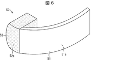
- FIG. 6 is a perspective view of the mold 50.
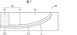
- FIG. 3 is a diagram showing a configuration of an injection molding apparatus 100 for performing injection molding for manufacturing the light guide plate 10. It is a figure which shows the structure of the injection molding apparatus 100 for performing injection molding for manufacture of a light-guide plate.
- a light guide plate is connected by connecting a first region having a curvature in the first direction (horizontal direction, a direction having an axis in the vertical direction) and a second region having a free curved surface in which the axis of curvature is not defined. It is a method of manufacturing a light guide plate manufactured by injection molding using a mold.
- the mold 50 includes a first member 51 and a second member 52.
- the first member 51 is an electroformed stamper used to form a region corresponding to a stereoscopic image forming portion of the light guide plate.
- the first member 51 is formed so as to have a predetermined curvature in the uniaxial direction (horizontal direction).
- the second member 52 is formed by using a mold part so as to have a free curved surface.
- the first member 51 and the second member 52 attached to the base 54 are connected so that the curved surface 51a and the curved surface 52a are on the same surface.
- a region A for molding the light guide plate 10 is formed in front of the surface formed by the curved surface 51a and the curved surface 52a.
- the light guide plate 10 is manufactured by injection molding using a mold having a first member 51 having a curvature in the first direction and a second member 52 having a free curved surface which is a predetermined curved surface. It As a result, in the light guide plate to be manufactured, (1) a stereoscopic image forming portion including an optical path changing portion group requiring high-precision molding can be formed in a region corresponding to the first member 51, and (2) a second. In the region corresponding to the member 52, a region having a free curved surface can be formed.
- FIG. 1 is a top view of the vehicle C in which the tail lamp unit 1A according to the present embodiment is installed.
- the + X direction in FIG. 1 will be referred to as the rear direction
- the ⁇ X direction as the forward direction
- the + Y direction as the upward direction
- the ⁇ Y direction as the downward direction
- the + Z direction as the right direction
- the ⁇ Z direction as the left direction. May be done.
- the tail lamp units 1A are provided on the left and right sides of the rear portion of the vehicle C, respectively.
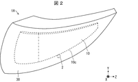
- FIG. 2 is a diagram showing the configuration of the tail lamp unit 1A on the right side of the vehicle C.
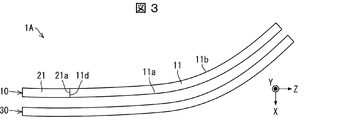
- FIG. 3 is a view of the tail lamp unit 1A as viewed from above.
- the configuration of the left tail lamp unit 1A of the vehicle C is the same as that of the right tail lamp unit 1A of the vehicle C, except that it is symmetrical.
- the tail lamp unit 1A includes a light source 2, a light guide plate 10, and a cover 30.
- the light source 2 and the light guide plate 10 form a stereoscopic image showing a tail lamp (also referred to as a tail light) and a brake lamp (also referred to as a braking light) of the vehicle C.
- a tail lamp also referred to as a tail light
- a brake lamp also referred to as a braking light
- the light source 2 emits light to the light guide plate 10.
- the light source 2 is, for example, an LED (Light Emitting diode) light source.
- the light source 2 is installed on the end surface 10c, which is the lower surface of the light guide plate 10.
- the light guide plate 10 guides the light emitted from the light source 2 and changes the optical path of the guided light by an optical path changing unit described later to form a stereoscopic image in space.
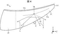
- FIG. 4 is a diagram showing the configuration of the light guide plate 10.
- the light guide plate 10 includes a stereoscopic image forming unit 11 (first region) and an auxiliary member 21 (second region).
- the light guide plate 10 is made of a resin material having transparency and a relatively high refractive index.
- the material forming the light guide plate 10 may be, for example, a polycarbonate resin, a polymethyl methacrylate resin, glass, or the like.
- the stereoscopic image forming unit 11 is a region in which an optical path changing unit for forming a stereoscopic image is formed, and is a member that constitutes the right side of the light guide plate 10.
- the three-dimensional image forming unit 11 has a curvature in the left-right direction, but does not have a curvature in the up-down direction.
- the three-dimensional image forming unit 11 has an emitting surface 11a that emits light, a back surface 11b opposite to the emitting surface 11a, and a surface that connects the emitting surface 11a and the back surface 11b.
- the end surface 11c is an incident surface on which the light emitted from the light source 2 is incident on the stereoscopic image forming unit 11.
- the stereoscopic image forming unit 11 guides the light from the light source 2 while spreading it in the Z-axis direction between the exit surface 11a and the back surface 11b.
- a plurality of optical path changing unit groups 13 are formed on the back surface 11b of the three-dimensional image forming unit 11.
- the optical path changing unit group 13 is formed substantially continuously in the horizontal direction.
- the optical path changing unit group 13 is formed by a part of the Fresnel lens. In FIG. 4, for simplification, only one optical path changing unit group 13 is shown.
- Light emitted from the light source 2 and guided by the stereoscopic image forming unit 11 is incident on each position in the Z-axis direction of the optical path changing unit group 13.
- the optical path changing unit group 13 substantially diverges the optical path of the light incident on each position of the optical path changing unit group 13 from a fixed point (hereinafter referred to as a convergence point PA) corresponding to each optical path changing unit group 13. Change to the direction.
- a convergence point PA a fixed point
- the light reflected at a certain point of the optical path changing unit group 13 travels in a direction along a straight line connecting the point and the convergence point PA.
- the divergent light L whose optical path has been changed by the optical path changing unit group 13 is emitted from the exit surface 11a of the stereoscopic image forming unit 11 toward the outside of the vehicle C.
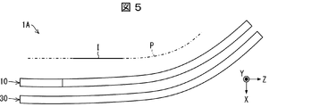
- FIG. 5 is a diagram showing a stereoscopic image I imaged by the stereoscopic image forming unit 11.
- the plurality of optical path changing unit groups 13 are formed in the three-dimensional image forming unit 11, and the convergence points of the plurality of optical path changing unit groups 13 are different from each other.
- a virtual image as a stereoscopic image I is formed on the stereoscopic image forming surface P by a collection of a plurality of convergence points corresponding to each optical path changing unit group 13. .
- the stereoscopic image I formed by the light emitted from the stereoscopic image forming unit 11 functions as the tail lamp and the brake lamp of the vehicle C.
- the auxiliary member 21 is a member for improving the design of the tail lamp unit 1A. As shown in FIGS. 3 and 4, the auxiliary member 21 is a member constituting the left side of the light guide plate 10. The auxiliary member 21 and the three-dimensional image forming unit 11 have a free curved surface. The left end of the auxiliary member 21 is curved so as to match the shape of the housing B of the vehicle C. As shown in FIG. 5, the light guide plate 10 is formed so that the auxiliary member 21, the right side surface 21 a, and the end surface 11 d of the three-dimensional image forming unit 11 are connected to each other.
- the cover 30 is a member that protects the light source 2 and the light guide plate 10, and is installed outside the light source 2 and the light guide plate 10 in the vehicle C.
- the left end of the cover 30 is curved so as to match the shape of the housing B of the vehicle C.
- the cover 30 is made of a transparent material.
- the cover 30 is composed of a smooth curved surface (in other words, a continuous curved surface). In other words, the cover 30 does not have protrusions or bends that cause discontinuous curved surfaces. As a result, the light emitted from the stereoscopic image forming unit 11 is not deflected in an unintended direction, so that it is possible to prevent the stereoscopic image I to be imaged from becoming unclear.
- the connecting surface between the housing B of the vehicle C and the cover is curved, while the connecting surface between the housing B of the vehicle C and the light guide plate is flat. Therefore, there is a problem that the appearance of the vehicle C is not good.
- the left ends of the light guide plate 10 and the cover 30 are curved so as to match the shape of the housing B of the vehicle C.
- both the connecting surface between the housing B of the vehicle C and the cover and the connecting surface between the housing B of the vehicle C and the light guide plate become curved surfaces.
- the design of the vehicle C can be enhanced.
- the light guide plate 10 of the present invention is manufactured by injection molding using a mold formed into a predetermined shape.
- FIG. 6 is a perspective view of the mold 50 used in the present embodiment. As shown in FIG. 6, the mold 50 includes a first member 51 and a second member 52.
- the first member 51 is an electroformed stamper (first electroformed stamper) used to form a region corresponding to the three-dimensional image forming unit 11 of the light guide plate 10.
- the manufacturing method of the first member 51 is as follows. First, an electroformed stamper in which a structure for forming the optical path changing unit group 13 included in the three-dimensional image forming unit 11 is formed on a metal flat plate is manufactured by an electroforming method. Next, by applying heat to the produced electroformed stamper, it is formed so as to have a predetermined curvature in the first direction (the direction corresponding to the left-right direction in the vehicle C). As a result, the first member 51 having the curved surface 51a on which the structure is formed is manufactured.
- the second member 52 is a member used to form a region corresponding to the stereoscopic image forming portion 11 of the light guide plate 10.
- the second member 52 does not need a structure for forming the optical path changing portion group 13, which is required to be formed with high accuracy. Therefore, the second member 52 can be molded by a method other than the electroforming method. Therefore, the second member 52 can be easily formed using a mold part so as to have a free curved surface.
- the curved surface 52a which is a surface used for injection molding of the second member 52, is mirror-finished.
- FIG. 7 is a diagram showing a configuration of an injection molding device 100 for performing injection molding for manufacturing the light guide plate 10.
- the first member 51 and the second member 52 attached to the base 54 are connected so that the curved surface 51a and the curved surface 52a are flush with each other.
- a region A for molding the light guide plate 10 is formed in front of the surface formed by the curved surface 51a and the curved surface 52a.
- the light guide plate 10 can be formed by using the conventional injection molding technique using the injection molding apparatus 100.
- the light guide plate 10 is manufactured by injection molding using a mold including the first member 51 having a horizontal curvature and the second member 52 having a free curved surface.
- the three-dimensional image forming unit 11 including the optical path changing unit group 13 that requires highly accurate molding can be formed, and (2) the second By forming the free curved surface in the region corresponding to the member 52, the auxiliary member 21 that conforms to the shape of the housing B of the vehicle C can be formed.
- the first member 51 on which the structure for forming the optical path changing portion group 13 is formed need only have a curvature in the horizontal direction. .. Therefore, the manufacturing cost of the first member 51 (and by extension, the light guide plate 10) can be suppressed.
- the light guide plate 10 in the present embodiment has a configuration in which only one side in the left-right direction has a free curved surface, but the light guide plate 10 of the present invention is not limited to this.
- the light guide plate 10 of one aspect of the present invention may have a configuration in which both sides in the left-right direction have free curved surfaces.
- Such a light guide plate can be manufactured by using a mold in which the second member 52 is arranged on both sides of the first member 51.
- the auxiliary member 21 in the present embodiment has a structure having a free curved surface, but may have a structure having a curvature in the vertical direction and the horizontal direction, or has a curvature in a direction other than the vertical direction and the horizontal direction. It may have a configuration.
- the second member 52 can be manufactured without performing high-precision control such as forming a structure for forming the optical path changing portion group 13. Therefore, the second member 52 can have an arbitrary curved surface.
- the light guide plate 10 in the present embodiment is a light guide plate that guides the light incident from the light source 2 and emits it from the emission surface 11a.
- the light guide plate 10 has a curvature in the first direction, guides the light emitted from the light source 2 and incident from the incident surface 11 a, and changes the optical path of the guided light by the optical path changing unit group 13.
- the three-dimensional image forming unit 11 that emits light from the exit surface 11a to form an image in space and one end of the three-dimensional image forming unit 11 in a direction having a curvature (that is, the first direction) are connected to a predetermined value.
- an auxiliary member 21 having a curved surface.
- the left end of the light guide plate 10 is curved so as to match the shape of the housing B of the vehicle C.
- both the connecting surface between the housing B of the vehicle C and the cover and the connecting surface between the housing B of the vehicle C and the light guide plate 10 are curved surfaces.
- the design of the vehicle C can be enhanced.
- the manufacturing method of the light guide plate 10 in the present embodiment is the same as the manufacturing method in the first embodiment except that the mold 60 is used instead of the mold 50 in the first embodiment.
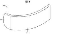
- FIG. 8 is a diagram showing the configuration of the mold 60 in this modified example. As shown in FIG. 8, the mold 60 includes a second member 53 instead of the second member 52 in the first embodiment.
- the second member 53 is an electroformed stamper (second electroformed stamper) used to form a region corresponding to the three-dimensional image forming unit 11 of the light guide plate 10.
- the second member 53 does not require a structure for forming the optical path changing portion group 13, which is required to be formed with high accuracy. Therefore, the second member 53 is manufactured by bending the electroformed stamper produced by the electroforming method in the biaxial direction by applying heat.
- the biaxial direction is a direction different from the first direction and the first direction.
- the biaxial directions may be the vertical direction and the horizontal direction, or may be other directions. Further, the two axes may be at any angle that is not perpendicular to each other.
- the radius of curvature in the vertical direction of the vehicle C may be 500 mm or more, and the radius of curvature in the horizontal direction of the vehicle C may be 200 mm or more.
- the second member 53 used for forming the region corresponding to the auxiliary member 21 of the light guide plate 10 is an electroformed stamper.
- the first member 51 and the second member 53 can be manufactured by the electroformed stamper without the need for a mold part having a free curved surface, so that the manufacturing cost of the light guide plate can be suppressed.
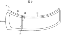
- FIG. 9 is a diagram showing a configuration of a tail lamp unit 1B as a modification of the tail lamp unit 1A in the first embodiment.
- FIG. 10 is a view of the tail lamp unit 1B viewed from above.
- the tail lamp unit 1B includes a cover 30A instead of the cover 30 in the first embodiment.
- the cover 30A includes a bent portion 31 in addition to the configuration of the cover 30 of the first embodiment.
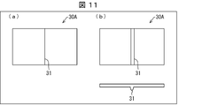
- FIG. 11A and (b) of FIG. 11 are diagrams showing specific examples of the bent portion 31.
- the bent portion 31 may be a line for dividing the cover 30A into two.
- the bent portion 31 may have a structure in which it is continuously bent.
- the bent portion 31 may have a convex structure protruding toward the outside of the vehicle C, or may have a concave structure concave toward the inside of the small amount C.
- the bent portion 31 is provided at a position overlapping the ridge line 15 formed on the light guide plate 10 when the tail lamp unit 1B is viewed from the rear direction.
- the ridge line 15 can be made inconspicuous.
- FIG. 12 is a diagram showing a configuration of a tail lamp unit 1C as a modification of the tail lamp unit 1A in the first embodiment.
- the tail lamp unit 1C includes a cover 30B instead of the cover 30 in the first embodiment.
- the cover 30B includes a reflective surface 32 in the configuration of the cover 30 of the first embodiment.
- the reflective surface 32 is formed on the outer surface 30Ba of the cover 30B.
- the reflection surface 32 is a surface that reflects the traveling direction of the light emitted from the emission surface 11a of the light guide plate 10 so as to be deflected at a larger angle with respect to the front-back direction of the vehicle C.
- the light emitted from the emission surface 11a of the light guide plate 10 can be deflected in a direction forming a larger angle with respect to the front-rear direction of the vehicle C.
- the stereoscopic image I can be visually recognized in a wider viewing angle range.
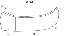
- FIG. 13 is a diagram showing a configuration of a light guide plate 10A as a modification of the light guide plate 10 in the first embodiment.
- the light guide plate 10A includes a stereoscopic image forming portion 11 (first region), an auxiliary member 21 (second region), and an auxiliary member 22 (second region).
- the auxiliary member 21 is connected only to one end of the stereoscopic image forming portion 11 (first region). More specifically, the auxiliary member 21 is connected only to one end of the stereoscopic image forming portion 11 in the direction having the curvature.
- the auxiliary member 21 and the auxiliary member 22 are formed at both ends of the three-dimensional image forming unit 11 in the direction having the curvature.
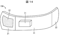
- FIG. 14 is a diagram showing how an image is formed by the light guide plate 10A.
- the auxiliary member 21 also has an optical path changing portion.
- the image I1 imaged by the stereoscopic image forming unit 11 in addition to the image I1 imaged by the stereoscopic image forming unit 11, the light emitted from the light source 2, passing through the stereoscopic image forming unit 11 and incident on the auxiliary member 21 is formed on the auxiliary member 21.
- the image I2 is formed by changing the optical path by the optical path changing unit. In this modification, the image I2 is imaged on the exit surface 21A of the auxiliary member 21, but the image I2 may be imaged in a space other than that.
- the auxiliary member 21 is formed by using the mold parts, the formation accuracy of the optical path changing portion formed on the auxiliary member 21 is higher than that when the optical path changing portion is formed on the stereoscopic image forming portion 11. Can not be raised. Therefore, the density of the optical path changing portion included in the auxiliary member 21 is smaller than the density of the optical path changing portion included in the stereoscopic image forming portion 11. In the light guide plate 10A in this modification, the density of the optical path changing portion included in the auxiliary member 21 is 50% or less of the density of the optical path changing portion included in the stereoscopic image forming portion 11. In the light guide plate 10A in this modification, the pattern shape of the optical path changing portion included in the stereoscopic image forming portion 11 and the pattern shape of the optical path changing portion included in the auxiliary member 21 are different.
- the auxiliary member 22 can be formed in the same manner as the method for forming the auxiliary member 21 described in the first embodiment.
- a method of manufacturing a light guide plate includes (1) a light having a curvature in a first direction, guiding light emitted from a light source and incident from an incident surface, and changing the optical path of the guided light.
- a light guide plate having a first region for forming an image in space by emitting light from an exit surface by changing the optical path depending on a portion and (2) a second region having a predetermined curved surface is injection-molded using a mold.
- the first member is manufactured by bending a first electrocast stamper on which a predetermined structure is formed by an electrocasting method in a direction corresponding to the first direction, and the second member has the predetermined curved surface.
- the light guide plate is manufactured by injection molding using the mold in which the first member and the second member are connected to each other.
- the first region bent in the uniaxial direction formed by the region corresponding to the first member of the mold and the predetermined curved surface formed by the region corresponding to the second member of the mold are formed. It is possible to manufacture a light guide plate that includes the second region that has.
- the second member is manufactured by a mold part including a surface for forming the predetermined curved surface.
- the second member can be manufactured to have an arbitrary free-form surface.
- the second member bends a second electroformed stamper formed by an electroforming method in a direction different from the first direction and the first direction. Manufactured by.
- the light guide plate according to one aspect of the present invention is manufactured by any of the above manufacturing methods.
- the light guide plate can be adapted to the shape of the device having the light guide plate or the like.
- the vehicle lamp according to one aspect of the present invention includes the light guide plate, a light source that emits light to the light guide plate, and a cover that protects the light guide plate and the light source.
- both the shape of the connecting surface between the light guide plate and the vehicle housing and the shape of the connecting surface between the cover and the vehicle housing can be curved.
- the design of the vehicle can be enhanced.
- the light guide plate is a light guide plate that guides light incident from a light source and emits it from an exit surface, has a curvature in the first direction, is emitted from the light source, and is incident from the incident surface. It has a first region in which the light is guided and the guided light is changed in the optical path by an optical path changing portion to be emitted from the exit surface to form an image in space, and the curvature of the first region. A second region connected to at least one end in the direction and having a predetermined curved surface.
- the second region is an optical path in which light emitted from the light source and incident from the incident surface is emitted from the exit surface by changing the optical path to form an image in space.
- the density of the optical path changing unit that includes the changing unit and that is included in the second region is 50% or less of the density of the optical path changing unit that is included in the first region.
- an image is formed on the emission surface of the second area by the light whose optical path is changed by the optical path changing unit included in the second area.
Landscapes
- Engineering & Computer Science (AREA)
- Physics & Mathematics (AREA)
- General Engineering & Computer Science (AREA)
- General Physics & Mathematics (AREA)
- Optics & Photonics (AREA)
- Manufacturing & Machinery (AREA)
- Mechanical Engineering (AREA)
- Non-Portable Lighting Devices Or Systems Thereof (AREA)
- Planar Illumination Modules (AREA)
- Light Guides In General And Applications Therefor (AREA)
- Moulds For Moulding Plastics Or The Like (AREA)
- Injection Moulding Of Plastics Or The Like (AREA)
Abstract
一部の領域において自由曲面を有する導光板を製造することを目的とする。第1方向に曲率を有する第1領域と、所定の曲面を有する第2領域とが接続された導光板を、金型(50)を用いた射出成型によって製造する導光板の製造方法であって、金型(50)は、第1領域を形成するための第1部材(51)と、第2領域を形成するための第2部材(52)とを備えている。第1部材(51)は、電鋳法によって所定の構造体が形成された第1電鋳スタンパを第1方向に対応する方向に屈曲させることにより製造される。
Description
本発明は、端面に自由曲面を有する導光板の製造方法などに関する。
照明装置や立体画像表示装置などに光を導光するための導光板が用いられている。このような導光板の製造方法が従来技術として知られている。
例えば、特許文献1には、所定の曲率半径に湾曲した導光板の製造方法が開示されている。特許文献1の技術では、導光板用基板に熱を加えることにより、所定の曲率半径に湾曲させている。
ここで、車両のテールランプユニットとして、導光板を備える立体表示装置を用いる場合がある。このようなテールランプユニットは、上記導光板と、当該導光板を保護するカバーとを備えている。テールランプユニットは、意匠性向上のため車両の筐体の形状に合わせるため、上下方向および左右方向の2軸方向において曲率を有することが好ましい。
導光板とカバーのうちカバーは、上下方向および左右方向の2軸方向において曲率を有する形状とすることは容易である。一方で、導光板は、光源から出射された光の光路を変更する光路変更部を形成する必要がある。しかしながら、特許文献1の技術では、導光板用基板に熱を加えることにより所定の曲率半径に湾曲させているため、1軸方向にしか曲率を持たせることができない。
本発明の一態様は、一部の領域において所定の曲面を有する導光板を製造することができる導光板の製造方法を実現することを目的とする。
上記の課題を解決するために、本発明の一態様に係る導光板の製造方法は、(1)第1方向に曲率を有し、光源から出射され入射面から入射された光を導光し、導光された光を光路変更部により光路変更させることにより出射面から出射させて空間に画像を結像させる第1領域と、(2)所定の曲面を有する第2領域とを有する導光板を、金型を用いた射出成型によって製造する導光板の製造方法であって、前記金型は、前記第1領域を形成するための第1部材と、前記第2領域を形成するための第2部材とを備えており、前記第1部材は、電鋳法によって所定の構造体が形成された第1電鋳スタンパを前記第1方向に対応する方向に屈曲させることにより製造され、前記第2部材は、前記所定の曲面を形成するように製造されており、前記第1部材と前記第2部材とが接続された前記金型を用いた射出成型によって前記導光板を製造する。
本発明の一態様によれば、部の領域において所定の曲面を有する導光板を製造することができる。
〔実施形態1〕
以下、本発明の一側面に係る実施の形態(以下、「本実施形態」とも表記する)を、図面に基づいて説明する。
以下、本発明の一側面に係る実施の形態(以下、「本実施形態」とも表記する)を、図面に基づいて説明する。
§1 適用例
まず、図6および図7を用いて、本発明の導光板の製造方法の一例について説明する。
まず、図6および図7を用いて、本発明の導光板の製造方法の一例について説明する。
図6は、金型50の斜視図である。導光板10の製造のための射出成型を行うための射出成型装置100の構成を示す図である。導光板の製造のための射出成型を行うための射出成型装置100の構成を示す図である。
本例は、第1方向(水平方向、上下方向に軸を有する方向)に曲率を有する第1領域と、曲率の軸が規定されない自由曲面を有する第2領域とが接続された導光板を、金型を用いた射出成型によって製造する導光板の製造方法である。
図6に示すように、金型50は、第1部材51と、第2部材52とを備えている。第1部材51は、導光板の立体画像形成部に対応する領域を形成するために用いられる電鋳スタンパである。第1部材51は、1軸方向(水平方向)に所定の曲率を有するように形成されている。一方、第2部材52は、自由曲面を有するように金型パーツを用いて形成されている。
図7に示すように、金型50は、ベース54に貼り付けられた第1部材51と、第2部材52とを、曲面51aと、曲面52aとが同一面になるように接続される。射出成型装置100には、曲面51aと曲面52aとによって構成される面の前方に、導光板10を成形するための領域Aが形成されている。
本例における導光板10の製造方法では、第1方向に曲率を有する第1部材51と、所定の曲面である自由曲面を有する第2部材52とを有する金型を用いて射出成型により製造される。これにより、製造する導光板において、(1)第1部材51に対応する領域において、高精度な成形が要求される光路変更部群を備える立体画像形成部を形成できるとともに、(2)第2部材52に対応する領域において、自由曲面を有する領域を形成することができる。
§2 構成例
以下、本発明のテールランプユニット1A(車両用灯具)の構成およびテールランプユニット1Aが備える導光板10の製造方法を、図面を参照して説明する。
以下、本発明のテールランプユニット1A(車両用灯具)の構成およびテールランプユニット1Aが備える導光板10の製造方法を、図面を参照して説明する。
(テールランプユニット1Aの構成)
図1は、本実施形態におけるテールランプユニット1Aが設置された車両Cの上面図である。以降では、説明の便宜上、図1における+X方向を後方向、-X方向を前方向、+Y方向を上方向、-Y方向を下方向、+Z方向を右方向、-Z方向を左方向として説明する場合がある。図1に示すように、テールランプユニット1Aは、車両Cの後部の左右にそれぞれ備え付けられている。
図1は、本実施形態におけるテールランプユニット1Aが設置された車両Cの上面図である。以降では、説明の便宜上、図1における+X方向を後方向、-X方向を前方向、+Y方向を上方向、-Y方向を下方向、+Z方向を右方向、-Z方向を左方向として説明する場合がある。図1に示すように、テールランプユニット1Aは、車両Cの後部の左右にそれぞれ備え付けられている。
図2は、車両Cの右側のテールランプユニット1Aの構成を示す図である。図3は、テールランプユニット1Aを上方向から見た図である。なお、車両Cの左側のテールランプユニット1Aの構成は、車両Cの右側のテールランプユニット1Aと左右対称になっている点を除いて同一の構成である。
図2および図3に示すように、テールランプユニット1Aは、光源2と、導光板10と、カバー30とを備えている。光源2および導光板10は、車両Cのテールランプ(尾灯とも呼ばれる)およびブレーキランプ(制動灯とも呼ばれる)を示す立体画像を結像させる。
光源2は、導光板10に光を出射する。光源2は、例えばLED(Light Emitting diode)光源である。光源2は、導光板10の下面である端面10cに設置されている。
導光板10は、光源2から出射された光を導光し、導光された光を後述する光路変更部により光路変更させることにより空間に立体画像を結像させる。
図4は、導光板10の構成を示す図である。導光板10は、図3および図4に示すように、立体画像形成部11(第1領域)と、補助部材21(第2領域)とからなっている。導光板10は、透明性および比較的高い屈折率を有する樹脂材料で成形されている。導光板10を形成する材料は、例えばポリカーボネイト樹脂、ポリメチルメタクリレート樹脂、ガラスなどであってよい。
立体画像形成部11は、立体画像を結像するための光路変更部が形成されている領域であり、導光板10の右側を構成する部材である。立体画像形成部11は、左右方向に曲率を有する一方で、上下方向には曲率を有していない。
立体画像形成部11は、光を出射する出射面11aと、出射面11aとは反対側の背面11bと、出射面11aと背面11bとを接続する面である、端面11c、端面11d、端面11eおよび端面11fとを備えている。端面11cは、光源2から出射された光が立体画像形成部11に入射する入射面である。立体画像形成部11は、光源2からの光を出射面11aと背面11bとの間においてZ軸方向に広げながら導光させる。
立体画像形成部11の背面11bには、複数の光路変更部群13が形成されている。光路変更部群13は、水平方向に実質的に連続して形成されている。光路変更部群13は、フレネルレンズの一部により形成されている。図4では、簡略化のため、1つの光路変更部群13のみを図示している。光路変更部群13のZ軸方向の各位置には、光源2から出射され立体画像形成部11によって導光された光が入射する。光路変更部群13は、光路変更部群13の各位置に入射した光の光路を、各光路変更部群13にそれぞれ対応する定点(以降では、収束点PAと呼称する)から実質的に発散する方向に変更する。光路変更部群13のある点で反射された光は、当該点と収束点PAとを結ぶ直線に沿った方向に進む。光路変更部群13により光路変更された発散光Lは、立体画像形成部11の出射面11aから車両Cの外部に向けて出射される。
図5は、立体画像形成部11により結像された立体画像Iを示す図である。立体画像形成部11には、上述したように複数の光路変更部群13が形成されており、複数の光路変更部群13の収束点が互い異なっている。これにより、立体画像形成部11では、図5に示すように、各光路変更部群13に対応する複数の収束点の集まりによって立体画像結像面Pに立体画像Iとしての虚像が形成される。すなわち、立体画像形成部11から出射された光によって結像された立体画像Iが車両Cのテールランプおよびブレーキランプとして機能する。
補助部材21は、テールランプユニット1Aの意匠性を向上させるための部材である。補助部材21は、図3および図4に示すように、導光板10の左側を構成する部材である。補助部材21は、立体画像形成部11は、自由曲面を有している。補助部材21は、左端が車両Cの筐体Bの形状に合うように曲面となっている。導光板10は、図5に示すように、補助部材21と右側の面21aと立体画像形成部11の端面11dとが接続するように形成されている。
カバー30は、光源2および導光板10を保護する部材であり、車両Cにおいて、光源2および導光板10に対して外側に設置されている。カバー30は、左端が車両Cの筐体Bの形状に合うように曲面となっている。カバー30は、透明性を有する材料で形成されている。
カバー30は、滑らかな曲面(換言すれば、連続的な曲面)で構成されている。換言すれば、カバー30は、不連続な曲面の原因となる突起や屈曲部などを有していない。これにより、立体画像形成部11から出射された光が意図しない方向に偏向されないため、結像する立体画像Iが不明瞭になることを防止することができる。
ここで、例えば、導光板の左端が曲面ではなく平面である場合について説明する。この場合、車両Cの筐体Bとカバーとの接続面は曲面となる一方で、車両Cの筐体Bと導光板との接続面は平面となる。そのため、車両Cの見栄えが良くないという問題がある。
これに対して、テールランプユニット1Aでは、導光板10およびカバー30の左端が車両Cの筐体Bの形状に合うように曲面となっている。これにより、車両Cの筐体Bとカバーとの接続面、および、車両Cの筐体Bと導光板との接続面はともに曲面となる。これにより、車両Cの意匠性を高くすることができる。
(導光板10の製造方法)
本発明の導光板10は、所定の形状に成形された金型を用いた射出成型により製造する。
本発明の導光板10は、所定の形状に成形された金型を用いた射出成型により製造する。
図6は、本実施形態で使用する金型50の斜視図である。図6に示すように、金型50は、第1部材51と、第2部材52とを備えている。
第1部材51は、導光板10の立体画像形成部11に対応する領域を形成するために用いられる電鋳スタンパ(第1電鋳スタンパ)である。第1部材51の製造方法は、以下のとおりである。まず、電鋳法によって金属の平板に立体画像形成部11が備える光路変更部群13を形成するための構造体が形成された電鋳スタンパを作製する。次に、作製した電鋳スタンパに対して熱を加えることにより第1方向(車両Cにおける左右方向に対応する方向)に所定の曲率を有するように形成する。これにより、上記構造体が形成された曲面51aを有する第1部材51を製造する。
第2部材52は、導光板10の立体画像形成部11に対応する領域を形成するために用いられる部材である。第2部材52は、高精度な形成が要求される、光路変更部群13を形成するための構造体が必要ではない。そのため、第2部材52は、電鋳法以外の方法で成形することができる。したがって、第2部材52は、自由曲面を有するように金型パーツを用いて容易に形成することができる。第2部材52の射出成型に用いられる面である曲面52aは、鏡面加工されている。
図7は、導光板10の製造のための射出成型を行うための射出成型装置100の構成を示す図である。図7に示すように、金型50は、ベース54に貼り付けられた第1部材51と、第2部材52とを、曲面51aと、曲面52aとが同一面になるように接続される。射出成型装置100には、曲面51aと曲面52aとによって構成される面の前方に、導光板10を成形するための領域Aが形成されている。導光板10は、射出成型装置100を用いて従来の射出成型技術を用いることにより形成することができる。
上記のように、本実施形態における導光板10の製造方法では、水平方向に曲率を有する第1部材51と、自由曲面を有する第2部材52とを有する金型を用いて射出成型により製造される。上記の構成によれば、(1)第1部材51に対応する領域において、高精度な成形が要求される光路変更部群13を備える立体画像形成部11を形成できるとともに、(2)第2部材52に対応する領域において、自由曲面を有することにより車両Cの筐体Bの形状に適合する補助部材21を形成することができる。
ここで、自由曲面を有し、かつ、光路変更部群13を形成するための構造体が形成された電鋳スタンパを作製することは技術的には可能である。しかしながら、このような電鋳スタンパを作製するためには、電鋳の複製が困難であり、製造コストが高くなってしまうという問題がある。
これに対して、本実施形態における導光板10の製造方法では、光路変更部群13を形成するための構造体が形成された第1部材51は水平方向にのみ曲率を有していればよい。そのため、第1部材51(ひいては、導光板10)の製造コストを抑えることができる。
本実施形態における導光板10では、左右方向の一方の側のみが自由曲面を有する構成であったが、本発明の導光板10はこれに限られない。本発明の一態様の導光板10では、左右方向の両側が自由曲面を有する構成であってもよい。このような導光板は、第1部材51の両側に第2部材52を配置させた金型を用いることによって製造することができる。
本実施形態における補助部材21は、自由曲面を有している構成であったが、上下方向および水平方向に曲率を有する構成であってもよいし、上下方向および水平方向以外の方向に曲率を有する構成であってもよい。第2部材52は、光路変更部群13を形成するための構造体を形成するような高精度な制御を行うことなく作製することができる。そのため、第2部材52は、任意の曲面にすることができる。
本実施形態における導光板10は、光源2から入射した光を導光して出射面11aから出射させる導光板である。導光板10は、上記の第1方向に曲率を有し、光源2から出射され入射面11aから入射された光を導光し、導光された光を光路変更部群13により光路変更させることにより出射面11aから出射させて空間に画像を結像させる立体画像形成部11と、立体画像形成部11の曲率を有する方向(すなわち、第1方向)の一方の端部に接続され、所定の曲面を有する補助部材21と、を有する。
上記の構成によれば、導光板10の左端が車両Cの筐体Bの形状に合うように曲面となっている。これにより、車両Cの筐体Bとカバーとの接続面、および、車両Cの筐体Bと導光板10との接続面はともに曲面となる。これにより、車両Cの意匠性を高くすることができる。
§3 変形例
以上、本発明の実施の形態を詳細に説明してきたが、前述までの説明はあらゆる点において本発明の例示に過ぎない。本発明の範囲を逸脱することなく種々の改良や変形を行うことができることは言うまでもない。例えば、以下のような変更が可能である。なお、以下では、上記実施形態と同様の構成要素に関しては同様の符号を用い、上記実施形態と同様の点については、適宜説明を省略した。以下の変形例は適宜組み合わせ可能である。
以上、本発明の実施の形態を詳細に説明してきたが、前述までの説明はあらゆる点において本発明の例示に過ぎない。本発明の範囲を逸脱することなく種々の改良や変形を行うことができることは言うまでもない。例えば、以下のような変更が可能である。なお、以下では、上記実施形態と同様の構成要素に関しては同様の符号を用い、上記実施形態と同様の点については、適宜説明を省略した。以下の変形例は適宜組み合わせ可能である。
<4.1>
本実施形態における導光板10の製造方法は、実施形態1における金型50に代えて金型60を用いる点を除いて実施形態1における製造方法と同様である。
本実施形態における導光板10の製造方法は、実施形態1における金型50に代えて金型60を用いる点を除いて実施形態1における製造方法と同様である。
図8は、本変形例における金型60の構成を示す図である。図8に示すように、金型60は、実施形態1における第2部材52に代えて第2部材53を備えている。
第2部材53は、導光板10の立体画像形成部11に対応する領域を形成するために用いられる電鋳スタンパ(第2電鋳スタンパ)である。第2部材53は、高精度な形成が要求される、光路変更部群13を形成するための構造体が必要ではない。そのため、第2部材53は、電鋳法によって作製された電鋳スタンパに対して熱を加えることにより2軸方向に屈曲させて製造される。2軸方向は、前記第1方向および前記第1方向と異なる方向である。例えば、2軸方向が上下方向および左右方向であってもよいし、それ以外の方向であってもよい。また、2軸が互いに垂直ではない任意の角度であってもよい。
上記のように導光板10をテールランプユニット1Aに適用する場合には、車両Cにおける上下方向には曲率半径が500mm以上、車両Cにおける左右方向には曲率半径が200mm以上とすればよい。
以上のように、本変形例の導光板10の製造方法では、導光板10の補助部材21に対応する領域を形成するために用いられる第2部材53が電鋳スタンパとなっている。これにより、自由曲面を有する金型パーツを必要とせず、電鋳スタンパによって第1部材51および第2部材53を製造することができるので、導光板の製造コストを抑制することができる。
<4.2>
実施形態1における製造方法で導光板10を製造した場合、導光板10における曲面51aと曲面52aとによって構成される面に、金型50における第1部材51と第2部材52との稜線に起因する稜線15が形成されることがある。そこで、本変形例では、稜線15を目立たなくすることができるテールランプユニットについて説明する。
実施形態1における製造方法で導光板10を製造した場合、導光板10における曲面51aと曲面52aとによって構成される面に、金型50における第1部材51と第2部材52との稜線に起因する稜線15が形成されることがある。そこで、本変形例では、稜線15を目立たなくすることができるテールランプユニットについて説明する。
図9は、実施形態1におけるテールランプユニット1Aの変形例としてのテールランプユニット1Bの構成を示す図である。図10は、テールランプユニット1Bを上方から見た図である。図9および図10に示すように、テールランプユニット1Bは、実施形態1におけるカバー30に代えてカバー30Aを備えている。カバー30Aは、実施形態1のカバー30の構成に加えて屈曲部31を備えている。
図11の(a)および(b)は、屈曲部31の具体例を示す図である。図11の(a)に示すように、屈曲部31は、カバー30Aを2つに分割するための線であってもよい。また、図11の(b)に示すように、屈曲部31は、連続的に屈曲した構造であってもよい。この場合、屈曲部31は、車両Cの外側に向けて突出した凸部構造であってもよいし、少量Cの内側に向けて凹んだ凹部構造であってもよい。
屈曲部31は、図10に示すように、テールランプユニット1Bを後方向から見たときに、導光板10に形成された稜線15と重なる位置に設けられている。これにより、導光板10に稜線15が形成された場合において、稜線15を目立たなくすることができる。
<4.2>
図12は、実施形態1におけるテールランプユニット1Aの変形例としてのテールランプユニット1Cの構成を示す図である。図12に示すように、テールランプユニット1Cは、実施形態1におけるカバー30に代えてカバー30Bを備えている。カバー30Bは、実施形態1のカバー30の構成に反射面32を備えている。
図12は、実施形態1におけるテールランプユニット1Aの変形例としてのテールランプユニット1Cの構成を示す図である。図12に示すように、テールランプユニット1Cは、実施形態1におけるカバー30に代えてカバー30Bを備えている。カバー30Bは、実施形態1のカバー30の構成に反射面32を備えている。
反射面32は、カバー30Bの外面30Baに形成されている。反射面32は、導光板10の出射面11aから出射された光の進行方向を車両Cの前後方向に対してより大きな角度に偏向するように反射する面である。
上記の構成によれば、導光板10の出射面11aから出射された光を車両Cの前後方向に対してより大きな角度をなす方向へ偏向させることができる。これにより、より広い視野角度範囲において立体画像Iを視認させることができる。
<4.3>
図13は、実施形態1における導光板10の変形例としての導光板10Aの構成を示す図である。図13に示すように、導光板10Aは、立体画像形成部11(第1領域)と、補助部材21(第2領域)と、補助部材22(第2領域)とからなっている。実施形態1における導光板10では、立体画像形成部11(第1領域)の一方の端部のみに補助部材21が接続されていた。より具体的には、立体画像形成部11の曲率を有する方向の一方の端部のみに補助部材21が接続されていた。これに対して、本変形例における導光板10Aでは、立体画像形成部11の曲率を有する方向の両端部に補助部材21および補助部材22がそれぞれ形成されている。
図13は、実施形態1における導光板10の変形例としての導光板10Aの構成を示す図である。図13に示すように、導光板10Aは、立体画像形成部11(第1領域)と、補助部材21(第2領域)と、補助部材22(第2領域)とからなっている。実施形態1における導光板10では、立体画像形成部11(第1領域)の一方の端部のみに補助部材21が接続されていた。より具体的には、立体画像形成部11の曲率を有する方向の一方の端部のみに補助部材21が接続されていた。これに対して、本変形例における導光板10Aでは、立体画像形成部11の曲率を有する方向の両端部に補助部材21および補助部材22がそれぞれ形成されている。
図14は、導光板10Aによって画像が形成されている様子を示す図である。図14に示すように、導光板10Aでは、補助部材21にも光路変更部が形成されている。また、導光板10Aでは、立体画像形成部11によって結像される画像I1に加えて、光源2から出射され立体画像形成部11を通り補助部材21に入射した光を補助部材21に形成された光路変更部によって光路変更することにより画像I2が結像される。本変形例では、画像I2は、補助部材21の出射面21Aに結像されるが、それ以外の空間に画像I2が結像されてもよい。
上述したように、補助部材21は、金型パーツを用いて形成されるため、立体画像形成部11に光路変更部を形成するときに比べて、補助部材21に形成する光路変更部の形成精度を高くすることができない。そのため、補助部材21が備える光路変更部の密度は、立体画像形成部11が備える光路変更部の密度よりも小さくなっている。本変形例における導光板10Aでは、補助部材21が備える光路変更部の密度は、立体画像形成部11が備える光路変更部の密度の50%以下となっている。本変形例における導光板10Aでは、立体画像形成部11が備える光路変更部のパターン形状と、補助部材21が備える光路変更部のパターン形状とが異なっている。
なお、補助部材22は、実施形態1にて説明した、補助部材21の形成方法と同様に形成することができる。
〔まとめ〕
本発明の一態様に係る導光板の製造方法は、(1)第1方向に曲率を有し、光源から出射され入射面から入射された光を導光し、導光された光を光路変更部により光路変更させることにより出射面から出射させて空間に画像を結像させる第1領域と、(2)所定の曲面を有する第2領域とを有する導光板を、金型を用いた射出成型によって製造する導光板の製造方法であって、前記金型は、前記第1領域を形成するための第1部材と、前記第2領域を形成するための第2部材とを備えており、前記第1部材は、電鋳法によって所定の構造体が形成された第1電鋳スタンパを前記第1方向に対応する方向に屈曲させることにより製造され、前記第2部材は、前記所定の曲面を形成するように製造されており、前記第1部材と前記第2部材とが接続された前記金型を用いた射出成型によって前記導光板を製造する。
本発明の一態様に係る導光板の製造方法は、(1)第1方向に曲率を有し、光源から出射され入射面から入射された光を導光し、導光された光を光路変更部により光路変更させることにより出射面から出射させて空間に画像を結像させる第1領域と、(2)所定の曲面を有する第2領域とを有する導光板を、金型を用いた射出成型によって製造する導光板の製造方法であって、前記金型は、前記第1領域を形成するための第1部材と、前記第2領域を形成するための第2部材とを備えており、前記第1部材は、電鋳法によって所定の構造体が形成された第1電鋳スタンパを前記第1方向に対応する方向に屈曲させることにより製造され、前記第2部材は、前記所定の曲面を形成するように製造されており、前記第1部材と前記第2部材とが接続された前記金型を用いた射出成型によって前記導光板を製造する。
上記の構成によれば、金型の第1部材に対応する領域によって形成される1軸方向に屈曲した第1領域と、金型の第2部材に対応する領域によって形成される所定の曲面を有する第2領域とを備える導光板を製造することができる。
本発明の一態様に係る導光板の製造方法において、前記第2部材は、前記所定の曲面を形成するための面を含む金型パーツにより製造される。
上記の構成によれば、第2部材を任意の自由曲面を有するように製造することができる。
本発明の一態様に係る導光板の製造方法において、前記第2部材は、電鋳法によって形成された第2電鋳スタンパを、前記第1方向および前記第1方向と異なる方向に屈曲させることにより製造される。
上記の構成によれば、任意の曲面を形成するための金型パーツを必要としないため、導光板の製造コストを抑制することができる。
本発明の一態様に係る導光板は、上記のいずれかの製造方法によって製造される。
上記の構成によれば、所定の曲面を有する第2領域を備えるため、当該導光板を有する装置などの形状に適応した導光板とすることができる。
本発明の一態様に係る車両用灯具は、上記の導光板と、前記導光板に光を出射する光源と、前記導光板および前記光源を保護するカバーと、を備える。
上記の構成によれば、導光板と車両の筐体との接続面の形状、およびカバーと車両の筐体との接続面の形状をともに曲面とすることができる。これにより、車両の意匠性を高くすることができる。
本発明の一態様に係る導光板は、光源から入射した光を導光して出射面から出射させる導光板であって、第1方向に曲率を有し、前記光源から出射され入射面から入射された光を導光し、導光された光を光路変更部により光路変更させることにより前記出射面から出射させて空間に画像を結像させる第1領域と、前記第1領域の曲率を有する方向の少なくとも一方の端部に接続され、所定の曲面を有する第2領域と、を有する。
本発明の一態様に係る導光板において、前記第2領域は、前記光源から出射され入射面から入射された光を光路変更させることにより前記出射面から出射させて空間に画像を結像させる光路変更部を備え、前記第2領域が備える前記光路変更部の密度は、前記第1領域が備える前記光路変更部の密度の50%以下である。
本発明の一態様に係る導光板において、前記第2領域が備える光路変更部によって光路変更された光によって前記第2領域の出射面に像が形成される。
本発明は上述した各実施形態に限定されるものではなく、請求項に示した範囲で種々の変更が可能であり、異なる実施形態にそれぞれ開示された技術的手段を適宜組み合わせて得られる実施形態についても本発明の技術的範囲に含まれる。
1A、1B、1C テールランプユニット(車両用灯具)
2 光源
10、10A 導光板
11 立体画像形成部(第1領域)
11a 出射面
13 光路変更部群
21 補助部材(第2領域)
30、30A、30B カバー
50、60 金型
51 第1部材
52、53 第2部材
2 光源
10、10A 導光板
11 立体画像形成部(第1領域)
11a 出射面
13 光路変更部群
21 補助部材(第2領域)
30、30A、30B カバー
50、60 金型
51 第1部材
52、53 第2部材
Claims (10)
- (1)第1方向に曲率を有し、光源から出射され入射面から入射された光を導光し、導光された光を光路変更部により光路変更させることにより出射面から出射させて空間に画像を結像させる第1領域と、(2)所定の曲面を有する第2領域とを有する導光板を、金型を用いた射出成型によって製造する導光板の製造方法であって、
前記金型は、前記第1領域を形成するための第1部材と、前記第2領域を形成するための第2部材とを備えており、
前記第1部材は、電鋳法によって所定の構造体が形成された第1電鋳スタンパを前記第1方向に対応する方向に屈曲させることにより製造され、
前記第2部材は、前記所定の曲面を形成するように製造されており、
前記第1部材と前記第2部材とが接続された前記金型を用いた射出成型によって前記導光板を製造する導光板の製造方法。 - 前記第2部材は、前記所定の曲面を形成するための面を含む金型パーツにより製造される請求項1に記載の導光板の製造方法。
- 前記第2部材は、電鋳法によって形成された第2電鋳スタンパを、前記第1方向および前記第1方向と異なる方向に屈曲させることにより製造される請求項1に記載の導光板の製造方法。
- 請求項1から3のいずれか1項に記載の製造方法によって製造された導光板。
- 請求項4に記載の導光板と、
前記導光板に光を出射する光源と、
前記導光板および前記光源を保護するカバーと、を備える車両用灯具。 - 光源から入射した光を導光して出射面から出射させる導光板であって、
第1方向に曲率を有し、前記光源から出射され入射面から入射された光を導光し、導光された光を光路変更部により光路変更させることにより前記出射面から出射させて空間に画像を結像させる第1領域と、
前記第1領域の曲率を有する方向の少なくとも一方の端部に接続され、所定の曲面を有する第2領域と、を有する導光板。 - 前記第2領域は、前記光源から出射され入射面から入射された光を光路変更させることにより前記出射面から出射させて空間に画像を結像させる光路変更部を備え、
前記第2領域が備える前記光路変更部の密度は、前記第1領域が備える前記光路変更部の密度よりも小さい請求項6に記載の導光板。 - 前記第2領域が備える前記光路変更部の密度は、前記第1領域が備える前記光路変更部の密度の50%以下である請求項6または7に記載の導光板。
- 前記第1領域が備える前記光路変更部のパターン形状と、前記第2領域が備える前記光路変更部のパターン形状とが異なっている、請求項7または8に記載の導光板。
- 前記第2領域が備える光路変更部によって光路変更された光によって前記第2領域の出射面に像が形成される請求項6~9のいずれか1項に記載の導光板。
Priority Applications (4)
| Application Number | Priority Date | Filing Date | Title |
|---|---|---|---|
| US17/431,342 US11674661B2 (en) | 2019-03-07 | 2020-03-09 | Method for manufacturing light guiding plate, light guiding plate, and lighting tool for vehicle |
| JP2021503680A JP7143932B2 (ja) | 2019-03-07 | 2020-03-09 | 導光板の製造方法、導光板、車両用灯具、および金型 |
| DE112020001104.6T DE112020001104T5 (de) | 2019-03-07 | 2020-03-09 | Verfahren zur herstellung einer lichtleiterplatte, eine lichterleitplatte und eine beleuchtungseinrichtung für fahrzeuge |
| CN202080013048.XA CN113412180B (zh) | 2019-03-07 | 2020-03-09 | 导光板的制造方法、导光板及车辆用灯具 |
Applications Claiming Priority (2)
| Application Number | Priority Date | Filing Date | Title |
|---|---|---|---|
| JP2019041962 | 2019-03-07 | ||
| JP2019-041962 | 2019-03-07 |
Publications (1)
| Publication Number | Publication Date |
|---|---|
| WO2020179936A1 true WO2020179936A1 (ja) | 2020-09-10 |
Family
ID=72337790
Family Applications (1)
| Application Number | Title | Priority Date | Filing Date |
|---|---|---|---|
| PCT/JP2020/010107 Ceased WO2020179936A1 (ja) | 2019-03-07 | 2020-03-09 | 導光板の製造方法、導光板および車両用灯具 |
Country Status (5)
| Country | Link |
|---|---|
| US (1) | US11674661B2 (ja) |
| JP (1) | JP7143932B2 (ja) |
| CN (1) | CN113412180B (ja) |
| DE (1) | DE112020001104T5 (ja) |
| WO (1) | WO2020179936A1 (ja) |
Cited By (1)
| Publication number | Priority date | Publication date | Assignee | Title |
|---|---|---|---|---|
| US20220291521A1 (en) * | 2021-03-12 | 2022-09-15 | Omron Corporation | Light guide, illuminator, and stereoscopic display |
Families Citing this family (1)
| Publication number | Priority date | Publication date | Assignee | Title |
|---|---|---|---|---|
| JP7860796B2 (ja) * | 2022-04-11 | 2026-05-18 | スタンレー電気株式会社 | 車両用灯具 |
Citations (4)
| Publication number | Priority date | Publication date | Assignee | Title |
|---|---|---|---|---|
| JP2000153543A (ja) * | 1998-09-16 | 2000-06-06 | Kuraray Co Ltd | 光学部品の成形方法 |
| JP2003123513A (ja) * | 2001-10-11 | 2003-04-25 | Three M Innovative Properties Co | 調光フィルム、ランプカバー及びランプ構造体 |
| JP2009155710A (ja) * | 2007-12-27 | 2009-07-16 | Tokai Rika Co Ltd | 微細構造体の製造方法 |
| JP2013125685A (ja) * | 2011-12-15 | 2013-06-24 | Hayamizu Denki Kogyo Kk | 導光板、照明装置、導光板の製造方法、および、照明装置の製造方法 |
Family Cites Families (25)
| Publication number | Priority date | Publication date | Assignee | Title |
|---|---|---|---|---|
| CA2060703C (en) * | 1992-02-05 | 1995-10-17 | Italo Caroli | Lens and method of making same |
| DE19757836C1 (de) * | 1997-12-24 | 1999-10-07 | Merten Gmbh & Co Kg Geb | Verfahren zur Herstellung eines doppelt-konvexen Linsenschirmes und Formkern zur Herstellung dieses Linsenschirmes |
| JP4544710B2 (ja) * | 1999-08-27 | 2010-09-15 | 株式会社メニコン | 眼用レンズ物品の成形型及び眼用レンズ物品の製造方法 |
| JP2002205321A (ja) * | 2001-01-11 | 2002-07-23 | Olympus Optical Co Ltd | 回転非対称光学面を有する光学素子の金型装置 |
| CN100437268C (zh) | 2004-07-09 | 2008-11-26 | 鸿富锦精密工业(深圳)有限公司 | 导光板模具及其制备方法 |
| TW200641416A (en) * | 2005-05-31 | 2006-12-01 | Bright View Electronics Co Ltd | A lighting device providing longitudinal illumination |
| JP5133081B2 (ja) * | 2007-02-14 | 2013-01-30 | パナソニック株式会社 | 面状照明装置及び液晶表示装置 |
| DE202007018495U1 (de) | 2007-02-26 | 2008-09-18 | Foliotec Gmbh | Verbundformteil |
| CN102414000A (zh) * | 2009-02-27 | 2012-04-11 | Hoya株式会社 | 透镜用铸模的制造方法及眼镜透镜的制造方法 |
| JP4530428B1 (ja) | 2009-04-27 | 2010-08-25 | 株式会社エス・ケー・ジー | 導光板の製造方法、導光板、バックライト装置、及び照明装置。 |
| FR2954457B1 (fr) * | 2009-12-21 | 2014-08-22 | Valeo Vision | Dispositif de signalisation pour vehicule avec effet optique 3d |
| EP2407292B1 (en) | 2010-07-14 | 2013-11-13 | Siemens Aktiengesellschaft | Negative mold comprising predefined foam blocks for casting a component and method for producing the negative mold |
| EP2548769B1 (en) * | 2011-07-18 | 2020-04-15 | Marelli Automotive Lighting Italy S.p.A. | Automotive rear light |
| JP5475169B2 (ja) * | 2013-05-29 | 2014-04-16 | 株式会社エス・ケー・ジー | 導光板及び照明装置 |
| JP2015052495A (ja) * | 2013-09-06 | 2015-03-19 | 株式会社リコー | 導光体、物体検出装置 |
| JP6247078B2 (ja) * | 2013-11-11 | 2017-12-13 | 株式会社小糸製作所 | 車両用灯具 |
| EP2965947B1 (de) | 2014-07-11 | 2019-12-25 | SMR Patents S.à.r.l. | Fahrtrichtungsanzeigemodul und Außenrückspiegelanordnung |
| CN104297999B (zh) * | 2014-09-26 | 2017-07-04 | 京东方科技集团股份有限公司 | 液晶模组和曲面显示装置 |
| WO2016059928A1 (ja) * | 2014-10-16 | 2016-04-21 | 株式会社 日立ハイテクノロジーズ | 曲面回折格子の型の製造方法、曲面回折格子の製造方法、曲面回折格子、および光学装置 |
| JP6531583B2 (ja) * | 2015-01-13 | 2019-06-19 | オムロン株式会社 | 光デバイス、光システム及び改札機 |
| EP3095642A1 (de) | 2015-05-19 | 2016-11-23 | Illinois Tool Works Inc. | Lichtleitvorrichtung mit verbesserter lichtabdeckung |
| JP6868974B2 (ja) | 2016-06-09 | 2021-05-12 | 株式会社小糸製作所 | 車輌用灯具 |
| JP6939577B2 (ja) | 2017-06-22 | 2021-09-22 | オムロン株式会社 | 車両用発光装置 |
| CN113375119B (zh) | 2017-06-22 | 2024-02-06 | 欧姆龙株式会社 | 车辆用发光装置 |
| CN108954214A (zh) * | 2018-05-31 | 2018-12-07 | 丽清汽车科技(上海)有限公司 | 一种轻薄型尾灯 |
-
2020
- 2020-03-09 CN CN202080013048.XA patent/CN113412180B/zh active Active
- 2020-03-09 DE DE112020001104.6T patent/DE112020001104T5/de active Pending
- 2020-03-09 WO PCT/JP2020/010107 patent/WO2020179936A1/ja not_active Ceased
- 2020-03-09 JP JP2021503680A patent/JP7143932B2/ja active Active
- 2020-03-09 US US17/431,342 patent/US11674661B2/en active Active
Patent Citations (4)
| Publication number | Priority date | Publication date | Assignee | Title |
|---|---|---|---|---|
| JP2000153543A (ja) * | 1998-09-16 | 2000-06-06 | Kuraray Co Ltd | 光学部品の成形方法 |
| JP2003123513A (ja) * | 2001-10-11 | 2003-04-25 | Three M Innovative Properties Co | 調光フィルム、ランプカバー及びランプ構造体 |
| JP2009155710A (ja) * | 2007-12-27 | 2009-07-16 | Tokai Rika Co Ltd | 微細構造体の製造方法 |
| JP2013125685A (ja) * | 2011-12-15 | 2013-06-24 | Hayamizu Denki Kogyo Kk | 導光板、照明装置、導光板の製造方法、および、照明装置の製造方法 |
Cited By (1)
| Publication number | Priority date | Publication date | Assignee | Title |
|---|---|---|---|---|
| US20220291521A1 (en) * | 2021-03-12 | 2022-09-15 | Omron Corporation | Light guide, illuminator, and stereoscopic display |
Also Published As
| Publication number | Publication date |
|---|---|
| CN113412180A (zh) | 2021-09-17 |
| DE112020001104T5 (de) | 2021-12-30 |
| JP7143932B2 (ja) | 2022-09-29 |
| US11674661B2 (en) | 2023-06-13 |
| US20220154908A1 (en) | 2022-05-19 |
| JPWO2020179936A1 (ja) | 2020-09-10 |
| CN113412180B (zh) | 2023-08-18 |
Similar Documents
| Publication | Publication Date | Title |
|---|---|---|
| US9400089B2 (en) | Vehicle lighting unit | |
| JP5165352B2 (ja) | 車両用信号灯 | |
| US8820990B2 (en) | Vehicle lamp and method for manufacturing a transparent element for a vehicle lamp | |
| CN104364579B (zh) | 车辆用灯具 | |
| JPH0668702A (ja) | 車両用灯具装置 | |
| CN103256564A (zh) | 用于机动车灯的光导体装置 | |
| EP3894743B1 (en) | Precollimator for a lighting device | |
| JP2016178024A (ja) | 車両用灯具 | |
| KR20130006072U (ko) | 차량용 하이 마운트 스톱 램프 | |
| JP2022515178A (ja) | 自動車前照灯用照明装置及び自動車前照灯 | |
| JP2017212070A (ja) | 車両用灯具 | |
| CN105393049B (zh) | 用于传播光束的具有反射图案的光波导管 | |
| JP7143932B2 (ja) | 導光板の製造方法、導光板、車両用灯具、および金型 | |
| JP7555282B2 (ja) | 車両用ランプ | |
| JP6531583B2 (ja) | 光デバイス、光システム及び改札機 | |
| US20190360659A1 (en) | Arranged light pipes for automotive lighting systems | |
| CN220355221U (zh) | 光导构件、照明或信号指示装置和机动车辆 | |
| CN107676732B (zh) | 光图案化装置与照明和/或信号指示设备 | |
| JP3985651B2 (ja) | 光束反射プリズム及び光束反射プリズムを用いた車両用灯具 | |
| JP7579744B2 (ja) | 車両用灯具 | |
| JP7707585B2 (ja) | 導光板デバイス | |
| JP2019179648A (ja) | 車両用灯具 | |
| JP2025001920A (ja) | 導光板、表示装置、移動体および金型 | |
| WO2026032437A1 (zh) | 光学组件、光学系统及车辆 | |
| JP2025139132A (ja) | 車両用灯具 |
Legal Events
| Date | Code | Title | Description |
|---|---|---|---|
| 121 | Ep: the epo has been informed by wipo that ep was designated in this application |
Ref document number: 20767260 Country of ref document: EP Kind code of ref document: A1 |
|
| ENP | Entry into the national phase |
Ref document number: 2021503680 Country of ref document: JP Kind code of ref document: A |
|
| 122 | Ep: pct application non-entry in european phase |
Ref document number: 20767260 Country of ref document: EP Kind code of ref document: A1 |