EP3095642A1 - Lichtleitvorrichtung mit verbesserter lichtabdeckung - Google Patents
Lichtleitvorrichtung mit verbesserter lichtabdeckung Download PDFInfo
- Publication number
- EP3095642A1 EP3095642A1 EP15168202.8A EP15168202A EP3095642A1 EP 3095642 A1 EP3095642 A1 EP 3095642A1 EP 15168202 A EP15168202 A EP 15168202A EP 3095642 A1 EP3095642 A1 EP 3095642A1
- Authority
- EP
- European Patent Office
- Prior art keywords
- light
- light guide
- guide body
- injection molding
- motor vehicle
- Prior art date
- Legal status (The legal status is an assumption and is not a legal conclusion. Google has not performed a legal analysis and makes no representation as to the accuracy of the status listed.)
- Withdrawn
Links
Images
Classifications
-
- B—PERFORMING OPERATIONS; TRANSPORTING
- B60—VEHICLES IN GENERAL
- B60Q—ARRANGEMENT OF SIGNALLING OR LIGHTING DEVICES, THE MOUNTING OR SUPPORTING THEREOF OR CIRCUITS THEREFOR, FOR VEHICLES IN GENERAL
- B60Q3/00—Arrangement of lighting devices for vehicle interiors; Lighting devices specially adapted for vehicle interiors
- B60Q3/60—Arrangement of lighting devices for vehicle interiors; Lighting devices specially adapted for vehicle interiors characterised by optical aspects
- B60Q3/62—Arrangement of lighting devices for vehicle interiors; Lighting devices specially adapted for vehicle interiors characterised by optical aspects using light guides
- B60Q3/64—Arrangement of lighting devices for vehicle interiors; Lighting devices specially adapted for vehicle interiors characterised by optical aspects using light guides for a single lighting device
-
- B—PERFORMING OPERATIONS; TRANSPORTING
- B29—WORKING OF PLASTICS; WORKING OF SUBSTANCES IN A PLASTIC STATE IN GENERAL
- B29C—SHAPING OR JOINING OF PLASTICS; SHAPING OF MATERIAL IN A PLASTIC STATE, NOT OTHERWISE PROVIDED FOR; AFTER-TREATMENT OF THE SHAPED PRODUCTS, e.g. REPAIRING
- B29C45/00—Injection moulding, i.e. forcing the required volume of moulding material through a nozzle into a closed mould; Apparatus therefor
- B29C45/03—Injection moulding apparatus
-
- B—PERFORMING OPERATIONS; TRANSPORTING
- B29—WORKING OF PLASTICS; WORKING OF SUBSTANCES IN A PLASTIC STATE IN GENERAL
- B29C—SHAPING OR JOINING OF PLASTICS; SHAPING OF MATERIAL IN A PLASTIC STATE, NOT OTHERWISE PROVIDED FOR; AFTER-TREATMENT OF THE SHAPED PRODUCTS, e.g. REPAIRING
- B29C45/00—Injection moulding, i.e. forcing the required volume of moulding material through a nozzle into a closed mould; Apparatus therefor
- B29C45/16—Making multilayered or multicoloured articles
-
- B—PERFORMING OPERATIONS; TRANSPORTING
- B60—VEHICLES IN GENERAL
- B60Q—ARRANGEMENT OF SIGNALLING OR LIGHTING DEVICES, THE MOUNTING OR SUPPORTING THEREOF OR CIRCUITS THEREFOR, FOR VEHICLES IN GENERAL
- B60Q3/00—Arrangement of lighting devices for vehicle interiors; Lighting devices specially adapted for vehicle interiors
- B60Q3/20—Arrangement of lighting devices for vehicle interiors; Lighting devices specially adapted for vehicle interiors for lighting specific fittings of passenger or driving compartments; mounted on specific fittings of passenger or driving compartments
- B60Q3/217—Doors, e.g. door sills; Steps
-
- F—MECHANICAL ENGINEERING; LIGHTING; HEATING; WEAPONS; BLASTING
- F21—LIGHTING
- F21S—NON-PORTABLE LIGHTING DEVICES; SYSTEMS THEREOF; VEHICLE LIGHTING DEVICES SPECIALLY ADAPTED FOR VEHICLE EXTERIORS
- F21S43/00—Signalling devices specially adapted for vehicle exteriors, e.g. brake lamps, direction indicator lights or reversing lights
- F21S43/20—Signalling devices specially adapted for vehicle exteriors, e.g. brake lamps, direction indicator lights or reversing lights characterised by refractors, transparent cover plates, light guides or filters
- F21S43/235—Light guides
- F21S43/236—Light guides characterised by the shape of the light guide
-
- F—MECHANICAL ENGINEERING; LIGHTING; HEATING; WEAPONS; BLASTING
- F21—LIGHTING
- F21S—NON-PORTABLE LIGHTING DEVICES; SYSTEMS THEREOF; VEHICLE LIGHTING DEVICES SPECIALLY ADAPTED FOR VEHICLE EXTERIORS
- F21S43/00—Signalling devices specially adapted for vehicle exteriors, e.g. brake lamps, direction indicator lights or reversing lights
- F21S43/20—Signalling devices specially adapted for vehicle exteriors, e.g. brake lamps, direction indicator lights or reversing lights characterised by refractors, transparent cover plates, light guides or filters
- F21S43/235—Light guides
- F21S43/242—Light guides characterised by the emission area
-
- G—PHYSICS
- G02—OPTICS
- G02B—OPTICAL ELEMENTS, SYSTEMS OR APPARATUS
- G02B1/00—Optical elements characterised by the material of which they are made; Optical coatings for optical elements
- G02B1/04—Optical elements characterised by the material of which they are made; Optical coatings for optical elements made of organic materials, e.g. plastics
- G02B1/045—Light guides
-
- G—PHYSICS
- G02—OPTICS
- G02B—OPTICAL ELEMENTS, SYSTEMS OR APPARATUS
- G02B6/00—Light guides; Structural details of arrangements comprising light guides and other optical elements, e.g. couplings
-
- G—PHYSICS
- G02—OPTICS
- G02B—OPTICAL ELEMENTS, SYSTEMS OR APPARATUS
- G02B6/00—Light guides; Structural details of arrangements comprising light guides and other optical elements, e.g. couplings
- G02B6/0001—Light guides; Structural details of arrangements comprising light guides and other optical elements, e.g. couplings specially adapted for lighting devices or systems
- G02B6/0011—Light guides; Structural details of arrangements comprising light guides and other optical elements, e.g. couplings specially adapted for lighting devices or systems the light guides being planar or of plate-like form
- G02B6/0033—Means for improving the coupling-out of light from the light guide
- G02B6/0035—Means for improving the coupling-out of light from the light guide provided on the surface of the light guide or in the bulk of it
- G02B6/0045—Means for improving the coupling-out of light from the light guide provided on the surface of the light guide or in the bulk of it by shaping at least a portion of the light guide
- G02B6/0046—Tapered light guide, e.g. wedge-shaped light guide
-
- G—PHYSICS
- G02—OPTICS
- G02B—OPTICAL ELEMENTS, SYSTEMS OR APPARATUS
- G02B6/00—Light guides; Structural details of arrangements comprising light guides and other optical elements, e.g. couplings
- G02B6/0001—Light guides; Structural details of arrangements comprising light guides and other optical elements, e.g. couplings specially adapted for lighting devices or systems
- G02B6/0011—Light guides; Structural details of arrangements comprising light guides and other optical elements, e.g. couplings specially adapted for lighting devices or systems the light guides being planar or of plate-like form
- G02B6/0081—Mechanical or electrical aspects of the light guide and light source in the lighting device peculiar to the adaptation to planar light guides, e.g. concerning packaging
- G02B6/0086—Positioning aspects
- G02B6/0091—Positioning aspects of the light source relative to the light guide
Definitions
- the invention relates to light-guiding devices for motor vehicles, in particular for decorative purposes and / or purposes of interior lighting or, for example, door threshold lighting of the motor vehicle.
- the object of the present invention is to improve the disadvantages of the prior art.
- the object is solved by the independent claims.
- Advantageous developments are defined in the subclaims.
- the object is achieved by a light-guiding device for a motor vehicle, wherein the light-guiding device has a light-guiding body of transparent plastic material, wherein the light-guiding body has at least one light-entry surface and at least one light-emitting surface, and wherein the light-guiding body is covered in one region by means of a substantially opaque cover material, wherein the cover material is applied to the area by means of an injection molding process.
- a light-guiding device according to the invention in a motor vehicle, preferably in an interior trim panel, particularly preferably in a door interior lining of the motor vehicle.
- Transparent plastic material is preferably understood as meaning a material with a transmittance of more than 50%, particularly preferably more than 70%, very particularly preferably more than 90%.
- the material is colorless and preferably clear.
- the light guide body is preferably formed in one piece.
- a light entry surface is preferably understood to mean an area of the light guide body via which, in the installed state of the light guide element, light from a light source, preferably an active light source (for example LED of the vehicle), is intentionally coupled into the light guide body.
- a light source preferably an active light source (for example LED of the vehicle)
- a light exit surface is preferably understood to be an area of the light guide body via which light is intentionally decoupled from the light guide body in the installed state, such that illumination of the vehicle interior or of an element in the vehicle interior (directly or indirectly) takes place through the light.
- the light exit surface is a visible surface, i. an area visible by a vehicle operator during normal use of the vehicle and its functions (i.e., without destroying the vehicle and removing panels).
- a substantially opaque cover material is preferably a material (at the layer thickness used in each case) with a transmittance of less than 50%, preferably less than 30%, more preferably less than 10% Understood.
- the cover material is dark or black, whereby a particularly effective light absorption and thus minimizes stray light.
- the material is light or white, whereby the light within the light guide can propagate more efficiently to the existing light exit surfaces.
- the layer thickness is so high that the unwanted scattered light is weak enough.
- the cover material has a light or white inner layer and a dark or black outer layer, which with efficient use of light and overall thin layer thickness of the two Abdeckmaterial füren a very good scattered light shielding is achieved.
- the two layers are preferably applied in the multi-component injection molding process.
- Bright are next to white, e.g. also the following colors according to Pantone® color system (lightest last): 692 C, 524 C, 243 C, 420 C, 707 C, 1895 C, 7520 C, Cool Gray 3 C, 250 C, 579 C, 671 C, 353 C , 5523 C, 7406 C, 5035 C, 7471 C, 2708 C, 565 C, 5595 C, 7501 C, 473 C, 1555 C, 382 C, 318 C, 2975 C, 516 C, 3375 C, 510 C, 2365 C, 4545 C, 136 C, 344 C, 4685 C, 5455 C, 605 C, 495 C, 217 C, 3245 C, 482 C, 459 C, 571 C, 713 C, 5875 C, 7534 C, 7632 C, 263 C, 489 C, 5175 C, 615 C, 182 C, 141 C, 468 C, 358 C, 538 C, 324 C, 5
- the following colors are also dark according to the Pantone® color system (darkest first): Black 6 C, 296 C, 5395 C, 7547 C, 5255 C, 2765 C, 282 C, 275 C, 2768 C, 532 C, 2766 C, 276 C, 274 C, 2755 C, 289 C, Neutral Black C, 273 C, 419 C, 5463 C, 539 C, 2757 C, 2745 C, 2965 C, 2748 C, 281 C, 2758 C, 433 C, 2695 C, 662 C, 2747 C, 2738 C, Black 3 C, 655 C, 303 C, 546 C, 280 C, 2685 C, 2627 C, Reflex Blue C, 426 C, 2756 C, 295 C, 2767 C, Black 4 C, 7463 C, 4975 C, Black C, 533 C, Blue 072 C, 2735 C, 5535 C, 547 C, 627 C, 2617 C, 648 C, 2746 C, 5467
- the covering material is fused to the light guide body, and particularly preferred that the cover material has been applied in the molten state to the light guide body.
- a plug-in device in particular connection socket, one of the existing light entry surfaces for a light source, e.g. LED, or a light guide, e.g. a glass fiber, formed.
- a corresponding plug-in device is formed during the injection molding of the cover material.
- the plug-in device is a connection socket, which has a central recess whose preferably collar-shaped edges consist of the cover material and at the bottom of which there is a light entry surface of the light guide body.
- one of the existing light entry surfaces has a concave entrance contour.
- a light entry surface is provided with a concave entry contour.
- the concave inlet contour is limited in a circle, wherein the circle diameter substantially corresponds to the diameter of an LED or glass fiber.
- the light guide device is installed in the motor vehicle and an LED or a glass fiber end (or other light guide) is at most 20 mm, preferably not more than 10 mm, more preferably not more than 3 mm from the concave inlet contour of this opposite arranged or preferably with this in contact and
- the diameter of this LED or glass fiber is equal to the diameter of the concave entrance contour, which is approximately circular.
- the region of the optical waveguide on which the covering material is applied makes up at least 60% of the surface of the optical waveguide which is not the light entry surface and not the light exit surface.
- the region makes up at least 70%, more preferably at least 90%, most preferably at least 99% of said surface, i. that in the last two cases, the light guide body, with the exception of the existing light entry surfaces and light exit surfaces is substantially encased by the cover material.
- the light-guiding device is a light-guiding device of an interior lining of a motor vehicle, in particular a door inner lining of a motor vehicle.
- the light-guiding device is installed in an interior lining of a motor vehicle, in particular a door inner lining of a motor vehicle.
- the light guide is installed so that the light exit surfaces are directed into the passenger compartment, so that the exiting light mainly radiates into the passenger compartment.
- the light guide body is produced by means of an injection molding process in the same injection molding machine, with which the masking occurs, and the light guiding device is thus produced in a multi-component injection molding process.
- the multi-component injection molding process is preferably a two-component injection molding process.
- the light guide body or a cavity-containing tool is rotated in its position.
- a cavity is preferably understood to mean a depression which has a negative contour of the component to be sprayed.
- the rotation takes place by means of a turntable tool, wherein the light guide is injected in a cavity in a turntable and then the turntable is rotated (eg by 180 °), the light guide is then introduced into another cavity (which has a contour for the cover material) , in which finally the covering material is injected onto the light guide body.
- the turntable on at least two cavities, and in a rotational position of the turntable at least two Lichtleitvoriquesen be injected, wherein in one light guide the light guide is injected and in the other light guide already the cover material is injected.
- the turntable method results in efficient production and is particularly preferred.
- the rotation takes place by means of an indexing tool, wherein after the first injection process (light-guiding body), plug-in inserts for contours are extended and rotated into another position.
- the sockets are e.g. held on pillars.
- a transfer takes place by means of a transfer method in which the light guide body is removed from the cavity after the first injection (eg by means of an automatic gripper) and into another cavity for the cover material is used and fixed there and then the cover material is injected to the light guide.
- a core-back method can be used, the contour being withdrawn after the first injection process, so that a free space is created between the light-conducting body and the contour, into which the covering material is subsequently injected.
- this method is suitable in particular for simple components without undercuts.
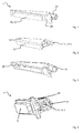
- FIG. 1 shows an example of a light guide device 1 according to the invention for a motor vehicle. It has a light guide body 10 made of transparent plastic material, the light guide body 10 having a light entry surface 11 and a light exit surface 12.
- the light guide body 10 is covered in a range of more than 90% of the surface, which is not light entrance surface 11 or light exit surface 12, by means of a substantially opaque cover material 20, which is applied to the area by means of an injection molding process.
- it is a light-guiding device 1 of a door inner lining of a motor vehicle.
- the surfaces around the light exit surface 12 are also not encapsulated here - these are later covered by another housing part of the door inner lining.
- FIG. 2 shows the light guide 10 of the light guide 1 from Fig. 1 ,
- the light guide body 10 is manufactured by means of an injection molding process in the same injection molding machine, with which the covering takes place.
- the light guide device 1 is thus produced in a two-component injection molding process.
- the light guide 10 is, after it has been sprayed and before the covering material 20 is sprayed onto the light guide body 10, rotated in its position by means of a turntable.
- FIG. 3 shows a separate view of the molded cover material 20 of the light guide 1 from Fig. 1 ,
- the cover material 20 is a plug-in device 21, here socket, the light entry surface 11 is formed for an LED.
- FIG. 4 shows one opposite Fig. 1 slightly rotated view of the light guide 1 from Fig. 1 in which, in particular, the entry contour 11.1 of the light entry surface 11 can be clearly seen.
Landscapes
- Engineering & Computer Science (AREA)
- Mechanical Engineering (AREA)
- Physics & Mathematics (AREA)
- General Physics & Mathematics (AREA)
- Optics & Photonics (AREA)
- Manufacturing & Machinery (AREA)
- General Engineering & Computer Science (AREA)
- Injection Moulding Of Plastics Or The Like (AREA)
- Non-Portable Lighting Devices Or Systems Thereof (AREA)
- Vehicle Interior And Exterior Ornaments, Soundproofing, And Insulation (AREA)
Abstract
Lichtleitvorrichtung (1) für ein Kraftfahrzeug, wobei die Lichtleitvorrichtung (1) einen Lichtleitkörper (10) aus durchsichtigem Kunststoffmaterial aufweist, wobei der Lichtleitkörper (10) mindestens eine Lichteintrittsfläche (11) und mindestens eine Lichtaustrittsfläche (12) aufweist und wobei der Lichtleitkörper (10) in einem Bereich mittels eines im Wesentlichen lichtundurchlässigen Abdeckmaterials (20) abgedeckt ist, wobei das Abdeckmaterial (20) mittels eines Spritzgussverfahrens auf den Bereich aufgebracht ist. Verwendung einer solchen Lichtleitvorrichtung (1) in einem Kraftfahrzeug und Verfahren zum Herstellen einer solchen Lichtleitvorrichtung (1).
Description
- Die Erfindung betrifft Lichtleitvorrichtungen für Kraftfahrzeuge, insbesondere zu dekorativen Zwecken und/oder Zwecken der Innenraumbeleuchtung oder bspw. Türschwellenbeleuchtung des Kraftfahrzeugs.
- Im Stand der Technik existieren derartige Lichtleitvorrichtungen, die nach dem Einbau an den Stellen, an denen kein Licht (Streulicht) austreten soll, mit einem Abdeckmaterial z.B. Klebeband/Klebefilz verdeckt werden. Die Erfinder befanden den Stand der Technik insofern als nachteilig, als dies zu aufwendigen Montagearbeiten und je nach aufgewendeter Abdeckung ungenügender Lichtabschottung führt.
- Aufgabe der vorliegenden Erfindung ist es, die Nachteile des Stands der Technik zu verbessern. Die Aufgabe wird durch die unabhängigen Ansprüche gelöst. Vorteilhafte Weiterbildungen sind in den Unteransprüchen definiert.
- Insbesondere wird die Aufgabe gelöst durch eine Lichtleitvorrichtung für ein Kraftfahrzeug, wobei die Lichtleitvorrichtung einen Lichtleitkörper aus durchsichtigem Kunststoffmaterial aufweist, wobei der Lichtleitkörper mindestens eine Lichteintrittsfläche und mindestens eine Lichtaustrittsfläche aufweist und wobei der Lichtleitkörper in einem Bereich mittels eines im Wesentlichen lichtundurchlässigen Abdeckmaterials abgedeckt ist, wobei das Abdeckmaterial mittels eines Spritzgussverfahrens auf den Bereich aufgebracht ist.
- Die Aufgabe wird weiterhin insbesondere gelöst durch die Verwendung einer erfindungsgemäßen Lichtleitvorrichtung in einem Kraftfahrzeug, bevorzugt in einer Innenraumverkleidung, besonders bevorzugt in einer Türinnenverkleidung des Kraftfahrzeugs.
- Die Aufgabe wird weiterhin insbesondere gelöst durch ein Verfahren zur Herstellung einer Lichtleitvorrichtung für ein Kraftfahrzeug, mit zumindest den folgenden Schritten:
- Herstellen eines Lichtleitkörpers aus durchsichtigem Kunststoffmaterial, wobei mindestens eine Lichteintrittsfläche und mindestens eine Lichtaustrittsfläche vorgesehen wird;
- Abdecken eines Bereichs des Lichtleitkörpers mittels eines im Wesentlichen undurchsichtigen Abdeckmaterials, wobei das Abdecken mittels eines Spritzgussverfahrens durchgeführt wird.
- Hierdurch wird eine sehr präzise Lichtabschottung erreicht und es können verschiedenste Abstrahlgeometrien bzw. Abschattungsgeometrien erreicht werden, da aufgrund des Aufspritzens des Abdeckmaterials der Gestaltung eine große Flexibilität gegeben ist, was z.B. bei Abdeckfilzen oder Abdeckbändern nicht möglich ist. Zudem ist das Verfahren in der Montage weniger aufwendig, da der Lichtleiter bereits das gewünschte Abstrahlverhalten aufweist. Die etwas komplexere Herstellung der Lichtleitvorrichtung fällt aufgrund des gut automatisierbaren Spritzgussverfahrens nicht ins Gewicht. Es müssen keine extra Bauteile zur Abdeckung vorgesehen werden, was auch Kosten spart. Zuletzt benötigt das Bauteil aufgrund der maßangepassten Abdeckung im Vergleich zu der bisherigen Abdecklösung weniger Bauraum.
- Unter durchsichtigem Kunststoffmaterial wird bevorzugt ein Material mit einem Transmissionsgrad von mehr als 50 %, besonders bevorzugt mehr als 70 %, ganz besonders bevorzugt mehr als 90 % verstanden. Bevorzugt ist das Material farblos und bevorzugt klar. Der Lichtleitkörper ist bevorzugt einstückig ausgebildet.
- Unter einer Lichteintrittsfläche wird bevorzugt eine Fläche des Lichtleitkörpers verstanden, über welche im eingebauten Zustand des Lichtleitelements Licht aus einer Lichtquelle, bevorzugt einer aktiven Lichtquelle (z.B. LED des Fahrzeugs), in den Lichtleitkörper willentlich eingekoppelt wird.
- Unter einer Lichtaustrittsfläche wird bevorzugt eine Fläche des Lichtleitkörpers verstanden, über welche im eingebauten Zustand Licht aus dem Lichtleitkörper willentlich ausgekoppelt wird, bevorzugt so, dass durch das Licht eine Beleuchtung des Fahrzeuginnenraums oder eines Elements im Fahrzeuginnenraum (direkt oder indirekt) stattfindet. Besonders bevorzugt ist die Lichtaustrittsfläche eine Sichtfläche, d.h. eine Fläche, welche von einem Fahrzeugführer bei normalem Gebrauch des Fahrzeugs und dessen Funktionen (d.h. ohne das Fahrzeug zu zerstören und Blenden abzunehmen) sichtbar ist.
- Unter einem im Wesentlichen lichtundurchlässigen Abdeckmaterial wird bevorzugt ein Material (bei der jeweils verwendeten Schichtdicke) mit einem Transmissionsgrad von weniger als 50 %, bevorzugt weniger als 30 %, besonders bevorzugt weniger als 10 % verstanden. Bevorzugt ist das Abdeckmaterial dunkel oder schwarz, wodurch eine besonders effektive Lichtabsorption und somit Streulichtminimierung erfolgt. Besonders bevorzugt ist das Material hell oder weiß, wodurch das Licht innerhalb des Lichtleitkörpers effizienter zu den vorhandenen Lichtaustrittsflächen propagieren kann. Bevorzugt ist dabei die Schichtdicke so hoch, dass das unerwünschte Streulicht schwach genug ist. Ganz besonders bevorzugt weist das Abdeckmaterial eine helle bzw. weiße innere Schicht und eine dunkle bzw. schwarze äußere Schicht auf, womit bei effizienter Lichtausnutzung und insgesamt dünner Schichtdicke der beiden Abdeckmaterialschichten eine sehr gute Streulichtabschirmung erzielt wird. Die beiden Schichten werden dabei bevorzugt im Mehrkomponentenspritzgussverfahren aufgebracht.
- Hell sind neben weiß z.B. auch die folgenden Farben nach Pantone® Farbsystem (hellste zuletzt): 692 C, 524 C, 243 C, 420 C, 707 C, 1895 C, 7520 C, Cool Gray 3 C, 250 C, 579 C, 671 C, 353 C, 5523 C, 7406 C, 5035 C, 7471 C, 2708 C, 565 C, 5595 C, 7501 C, 473 C, 1555 C, 382 C, 318 C, 2975 C, 516 C, 3375 C, 510 C, 2365 C, 4545 C, 136 C, 344 C, 4685 C, 5455 C, 605 C, 495 C, 217 C, 3245 C, 482 C, 459 C, 571 C, 713 C, 5875 C, 7534 C, 7632 C, 263 C, 489 C, 5175 C, 615 C, 182 C, 141 C, 468 C, 358 C, 538 C, 324 C, 552 C, 503 C, 352 C, 162 C, 304 C, 5807 C, 684 C, 149 C, 580 C, 7548 C, 366 C, 332 C, 719 C, 474 C, 584 C, 7405 C, 123 C, Cool Gray 2 C, 678 C, 531 C, 635 C, 135 C, 1355 C, 699 C, 5245 C, 1225 C, 196 C, 381 C, 517 C, 544 C, 7478 C, 572 C, 610 C, 7500 C, 496 C, 7527 C, 427 C, 129 C, Warm Gray 1 C, 2706 C, 290 C, 351 C, 712 C, 643 C, 614 C, 566 C, 116 C, 389 C, 2707 C, 7486 C, 691 C, 677 C, 365 C, 148 C, 628 C, 460 C, 657 C, 155 C, 7457 C, 109 C, 7403 C, 545 C, Green 0921 C, 128 C, 475 C, 122 C, 604 C, 650 C, 331 C, 7422 C, 585 C, 1345 C, 5315 C, 573 C, 134 C, 7485 C, 396 C, 7604 C, 317 C, Cool Gray 1 C, 3965 C, 706 C, 7402 C, 374 C, 7507 C, 670 C, 7404 C, Yellow 012 C, 609 C, 380 C, 642 C, 121 C, 3955 C, Medium Yellow C, 7443 C, 1215 C, 698 C, 621 C, 115 C, 586 C, 603 C, 108 C, 664 C, 127 C, 461 C, 120 C, 388 C, 7506 C, 373 C, 114 C, 608 C, Yellow C, 587 C, 7541 C, 387 C, 113 C, 7436 C, 379 C, 107 C, 372 C, 3945 C, 649 C, 395 C, 705 C, 607 C, 1205 C, 102 C, 663 C, 394 C, 7401 C, 106 C, 656 C, 602 C, 386 C, 3935 C, 7499 C, 601 C, 101 C, 803 C, 393 C, 100 C, 600 C, Yellow 0131 C.
- Dunkel sind neben schwarz z.B. auch die folgenden Farben nach Pantone® Farbsystem (dunkelste zuerst): Black 6 C, 296 C, 5395 C, 7547 C, 5255 C, 2765 C, 282 C, 275 C, 2768 C, 532 C, 2766 C, 276 C, 274 C, 2755 C, 289 C, Neutral Black C, 273 C, 419 C, 5463 C, 539 C, 2757 C, 2745 C, 2965 C, 2748 C, 281 C, 2758 C, 433 C, 2695 C, 662 C, 2747 C, 2738 C, Black 3 C, 655 C, 303 C, 546 C, 280 C, 2685 C, 2627 C, Reflex Blue C, 426 C, 2756 C, 295 C, 2767 C, Black 4 C, 7463 C, 4975 C, Black C, 533 C, Blue 072 C, 2735 C, 5535 C, 547 C, 627 C, 2617 C, 648 C, 2746 C, 5467 C, 540 C, Black 2 C, 288 C, 7449 C, 294 C, Black 5 C, 440 C, 412 C, 5605 C, Dark Blue C, 2607 C, 669 C, Violet C, 7546 C, 309 C, 534 C, 287 C, Medium Purple C, 2955 C, 560 C, 4625 C, 548 C, 2736 C, 302 C, 7645 C, 567 C, 3035 C, 262 C, 5115 C, 504 C, 654 C, 5185 C, 7421 C, 497 C, 447 C, 439 C, 518 C, 690 C, Black 7 C, 541 C, 7631 C, 2597 C, 7533 C, 661 C, 490 C, 286 C, 7644 C, 476 C, 3308 C, 7652 C, 229 C, 2623 C, 222 C, 432 C, 3435 C, 7694 C, 525 C, 269 C, 261 C, 7448 C, 5265 C, 4695 C, 316 C, 7554 C, 511 C, 553 C, 2613 C, 260 C, 483 C, 5747 C, 519 C, 732 C, 209 C, 7630 C, 7680 C, 7428 C, 3302 C, 7643 C, 188 C, 448 C, 268 C, 1817 C, 293 C, 7650 C, 446 C, 7651 C.
- Mittels eines Spritzgussverfahrens auf den Bereich aufgebracht bedeutet bevorzugt, dass das Abdeckmaterial an den Lichtleitkörper angeschmolzen ist, und besonders bevorzugt, dass das Abdeckmaterial im geschmolzenen Zustand auf den Lichtleitkörper aufgebracht worden ist.
- In einem weiter bevorzugten Ausführungsbeispiel der vorliegenden Erfindung ist mittels des Abdeckmaterials eine Steckeinrichtung, insbesondere Anschlussbuchse, einer der vorhandenen Lichteintrittsflächen für eine Lichtquelle, z.B. LED, oder einen Lichtleiter, z.B. eine Glasfaser, ausgebildet. In einem weiter bevorzugten Verfahren wird eine entsprechende Steckeinrichtung während des Spritzgießens des Abdeckmaterials ausgebildet.
- Hierdurch ist eine einfache Verbindungsmöglichkeit mit der Lichtquelle gegeben, wobei die Verbindungsmöglichkeit bereits per se lichtdicht ausgestaltet sein kann. Bevorzugt ist die Steckeinrichtung eine Anschlussbuchse, welche eine zentrale Ausnehmung aufweist, deren bevorzugt kragenförmige Ränder aus dem Abdeckmaterial bestehen und an deren Boden sich eine Lichteintrittsfläche des Lichtleitkörpers befindet.
- In einem weiter bevorzugten Ausführungsbeispiel der vorliegenden Erfindung weist eine der vorhandenen Lichteintrittsflächen eine konkave Eintrittskontur auf. In einem weiter bevorzugten Verfahren wird eine Lichteintrittsfläche mit einer konkaven Eintrittskontur versehen.
- Hierdurch ist eine effektive Lichteinkopplung aus einer LED oder Glasfaser gegeben. Bevorzugt ist die konkave Eintrittskontur kreisförmig begrenzt, wobei der Kreisdurchmesser dem Durchmesser einer LED oder Glasfaser im Wesentlichen entspricht. Bevorzugt ist die Lichtleitvorrichtung in dem Kraftfahrzeug eingebaut und eine LED oder ein Glasfaserende (oder ein anderer Lichtleitkörper) ist maximal 20 mm, bevorzugt maximal 10 mm besonders bevorzugt maximal 3 mm von der konkaven Eintrittskontur entfernt von dieser gegenüberliegend angeordnet oder bevorzugt mit dieser in Kontakt und bevorzugt ist der Durchmesser dieser LED oder Glasfaser gleich dem Durchmesser der konkaven Eintrittskontur, die annähernd kreisförmig ist.
- In einem weiter bevorzugten Ausführungsbeispiel der vorliegenden Erfindung macht der Bereich des Lichtleitkörpers, auf den das Abdeckmaterial aufgebracht ist, mindestens 60% der Oberfläche des Lichtleitkörpers, die nicht Lichteintrittsfläche und nicht Lichtaustrittsfläche ist, aus.
- Hierdurch wird eine sehr großflächige Lichtabschottung erreicht, so dass Licht nur dorthin gelangt, wo es austreten soll. Bevorzugt macht der Bereich mindestens 70 %, besonders bevorzugt mindestens 90 %, ganz besonders bevorzugt mindestens 99 % der besagten Oberfläche aus, d.h. dass in den letzten beiden Fällen, der Lichtleitkörper mit Ausnahme der vorhandenen Lichteintrittsflächen und Lichtaustrittsflächen im Wesentlichen durch das Abdeckmaterial ummantelt ist.
- In einem weiter bevorzugten Ausführungsbeispiel der vorliegenden Erfindung ist die Lichtleitvorrichtung eine Lichtleitvorrichtung einer Innenraumverkleidung eines Kraftfahrzeugs, insbesondere einer Türinnenverkleidung eines Kraftfahrzeugs. In einem weiter bevorzugten Verfahren wird die Lichtleitvorrichtung in eine Innenraumverkleidung eines Kraftfahrzeugs, insbesondere eine Türinnenverkleidung eines Kraftfahrzeugs eingebaut.
- Bevorzugt ist die Lichtleitvorrichtung so verbaut, dass die Lichtaustrittsflächen in den Fahrgastinnenraum gerichtet sind, so dass das austretende Licht hauptsächlich in den Fahrgastinnenraum strahlt.
- In einem weiter bevorzugten Verfahren der vorliegenden Erfindung wird der Lichtleitkörper mittels eines Spritzgussverfahrens in derselben Spritzgussmaschine hergestellt, mit welcher das Abdecken erfolgt, und die Lichtleitvorrichtung wird somit in einem Mehrkomponentenspritzgussverfahren hergestellt.
- Hierdurch ist eine sehr effiziente Herstellung der Lichtleitvorrichtung gegeben. Das Mehrkomponentenspritzgussverfahren ist bevorzugt ein Zweikomponentenspritzgussverfahren.
- In einem weiter bevorzugten Verfahren der vorliegenden Erfindung wird, nachdem der Lichtleitkörper gespritzt wurde und bevor das Abdeckmaterial an den Lichtleitkörper angespritzt wird, der Lichtleitkörper oder ein eine Kavität enthaltendes Werkzeug in seiner Position verdreht.
- Hierdurch wird der Spritzvorgang effizient durchgeführt. Unter einer Kavität wird bevorzugt eine Mulde verstanden, welche eine Negativkontur des zu spritzenden Bauteils aufweist.
- Bevorzugt erfolgt das Verdrehen mittels eines Drehtellerwerkzeugs, wobei der Lichtleitkörper in einer Kavität in einem Drehteller gespritzt wird und dann der Drehteller gedreht wird (z.B. um 180°), der Lichtleitkörper anschließend in eine andere Kavität eingeführt wird (welche eine Kontur für das Abdeckmaterial aufweist), in welcher schließlich das Abdeckmaterial an den Lichtleitkörper gespritzt wird. Bevorzugt weist der Drehteller mindestens zwei Kavitäten auf, und in einer Drehposition des Drehtellers werden mindestens zwei Lichtleitvorrichtungen gespritzt, wobei bei der einen Lichtleitvorrichtung der Lichtleitkörper gespritzt wird und bei der anderen Lichtleitvorrichtung bereits das Abdeckmaterial gespritzt wird. Das Drehtellerverfahren führt zu einer effizienten Produktion und ist besonders bevorzugt.
- Alternativ zum Verdrehen mittels des Drehtellerwerkzeugs erfolgt das Verdrehen mittels eines Indexwerkzeugs, wobei nach dem ersten Spritzvorgang (Lichtleitkörper) Steckeinsätze für Konturen ausfahren und in eine andere Position verdreht werden. Die Steckeinsätze sind z.B. an Säulen gehalten.
- Alternativ zum Verdrehen mittels Drehtellerwerkzeug oder Indexwerkzeug erfolgt ein Umsetzen, bevorzugt mit Verdrehen, mittels eines Umsetzverfahrens, bei welchem der Lichtleitkörper nach dem ersten Spritzen aus der Kavität herausgenommen wird (z.B. mittels eines automatischen Greifers), und in einen andere Kavität für das Abdeckmaterial eingesetzt und dort fixiert wird und sodann das Abdeckmaterial an den Lichtleitkörper gespritzt wird.
- Alternativ zu einem Verdrehen kann ein Core Back Verfahren angewendet werden, wobei nach dem ersten Spritzvorgang die Kontur zurückgezogen wird, so dass ein Freiraum zwischen dem Lichtleitkörper und der Kontur entsteht, in welchen dann anschließend das Abdeckmaterial gespritzt wird. Dieses Verfahren eignet sich je nach Geometrie der Lichtleitvorrichtung insbesondere bei einfachen Bauteilen ohne Hinterschneidungen.
- Die Erfindung soll nun anhand von Zeichnungen beispielhaft weiter veranschaulicht werden. Hierbei zeigen:
-
Figur 1 ein Beispiel einer erfindungsgemäßen Lichtleitvorrichtung, -
Figur 2 den Lichtleitkörper der Lichtleitvorrichtung ausFig. 1 -
Figur 3 eine separate Ansicht des um den Lichtleitkörper umspritzten Abdeckmaterials der Lichtleitvorrichtung ausFig. 1 -
Figur 4 eine gegenüberFig. 1 etwas gedrehte Ansicht der Lichtleitvorrichtung ausFig. 1 , in welcher insbesondere die Eintrittskontur gut zu erkennen ist. -
Figur 1 zeigt ein Beispiel einer erfindungsgemäßen Lichtleitvorrichtung 1 für ein Kraftfahrzeug. Sie weist einen Lichtleitkörper 10 aus durchsichtigem Kunststoffmaterial auf, wobei der Lichtleitkörper 10 eine Lichteintrittsfläche 11 und eine Lichtaustrittsfläche 12 aufweist. Der Lichtleitkörper 10 ist in einem Bereich von mehr als 90 % der Oberfläche, die nicht Lichteintrittsfläche 11 oder Lichtaustrittsfläche 12 ist, mittels eines im Wesentlichen lichtundurchlässigen Abdeckmaterials 20 abgedeckt, welches mittels eines Spritzgussverfahrens auf den Bereich aufgebracht ist. Ferner handelt es sich um eine Lichtleitvorrichtung 1 einer Türinnenverkleidung eines Kraftfahrzeugs. Die Flächen rings um die Lichtaustrittsfläche 12 sind hier ebenfalls nicht umspritzt - diese werden später durch ein anderes Gehäuseteil der Türinnenverkleidung abgedeckt. - Die Herstellung beinhaltet die folgenden Schritte:
- Herstellen des Lichtleitkörpers 10 aus durchsichtigem Kunststoffmaterial, wobei hierbei die Lichteintrittsfläche 11 und die Lichtaustrittsfläche 12 ausgeformt werden;
- Abdecken des Bereichs des Lichtleitkörpers 10 mittels des im Wesentlichen undurchsichtigen Abdeckmaterials 20, wobei das Abdecken mittels eines Spritzgussverfahrens durchgeführt wird.
-
Figur 2 zeigt den Lichtleitkörper 10 der Lichtleitvorrichtung 1 ausFig. 1 . In diesem Beispiel wird der Lichtleitkörper 10 mittels eines Spritzgussverfahrens in derselben Spritzgussmaschine hergestellt, mit welcher das Abdecken erfolgt. Die Lichtleitvorrichtung 1 wird somit in einem Zweikomponentenspritzgussverfahren hergestellt. Der Lichtleitkörper 10 wird, nachdem er gespritzt wurde und bevor das Abdeckmaterial 20 an den Lichtleitkörper 10 angespritzt wird, in seiner Position mittels eines Drehtellers verdreht. -
Figur 3 zeigt eine separate Ansicht des angespritzten Abdeckmaterials 20 der Lichtleitvorrichtung 1 ausFig. 1 . Mittels des Abdeckmaterials 20 ist eine Steckeinrichtung 21, hier Anschlussbuchse, der Lichteintrittsfläche 11 für eine LED ausgebildet. -
Figur 4 zeigt eine gegenüberFig. 1 etwas gedrehte Ansicht der Lichtleitvorrichtung 1 ausFig. 1 , in welcher insbesondere die Eintrittskontur 11.1 der Lichteintrittsfläche 11 gut zu erkennen ist. -
- 1
- Lichtleitvorrichtung
- 10
- Lichtleitkörper
- 11.1
- Eintrittskontur
- 11
- Lichteintrittsfläche
- 12
- Lichtaustrittsfläche
- 20
- Abdeckmaterial
- 21
- Steckeinrichtung
Claims (9)
- Lichtleitvorrichtung (1) für ein Kraftfahrzeug, wobei die Lichtleitvorrichtung (1) einen Lichtleitkörper (10) aus durchsichtigem Kunststoffmaterial aufweist, wobei der Lichtleitkörper (10) mindestens eine Lichteintrittsfläche (11) und mindestens eine Lichtaustrittsfläche (12) aufweist und wobei der Lichtleitkörper (10) in einem Bereich mittels eines im Wesentlichen lichtundurchlässigen Abdeckmaterials (20) abgedeckt ist,
dadurch gekennzeichnet, dass das Abdeckmaterial (20) mittels eines Spritzgussverfahrens auf den Bereich aufgebracht ist. - Lichtleitvorrichtung (1) gemäß Anspruch 1, wobei mittels des Abdeckmaterials (20) eine Steckeinrichtung (21), insbesondere Anschlussbuchse, einer der vorhandenen Lichteintrittsflächen (11) für eine Lichtquelle oder einen Lichtleiter ausgebildet ist.
- Lichtleitvorrichtung (1) gemäß einem der vorhergehenden Ansprüche, wobei eine der vorhandenen Lichteintrittsflächen (11) eine konkave Eintrittskontur (11.1) aufweist.
- Lichtleitvorrichtung (1) gemäß einem der vorhergehenden Ansprüche, wobei der Bereich des Lichtleitkörpers (10), auf den das Abdeckmaterial (20) aufgebracht ist, mindestens 60% der Oberfläche des Lichtleitkörpers (10), die nicht Lichteintrittsfläche (11) und nicht Lichtaustrittsfläche (12) ist, ausmacht.
- Lichtleitvorrichtung (1) gemäß einem der vorhergehenden Ansprüche, wobei die Lichtleitvorrichtung (1) eine Lichtleitvorrichtung (1) einer Innenraumverkleidung eines Kraftfahrzeugs ist.
- Verwendung einer Lichtleitvorrichtung (1) gemäß einem der vorhergehenden Ansprüche in einem Kraftfahrzeug, bevorzugt in einer Innenraumverkleidung, besonders bevorzugt in einer Türinnenverkleidung des Kraftfahrzeugs.
- Verfahren zur Herstellung einer Lichtleitvorrichtung (1) für ein Kraftfahrzeug, mit zumindest den folgenden Schritten:- Herstellen eines Lichtleitkörpers (10) aus durchsichtigem Kunststoffmaterial, wobei mindestens eine Lichteintrittsfläche (11) und mindestens eine Lichtaustrittsfläche (12) vorgesehen wird;- Abdecken eines Bereichs des Lichtleitkörpers (10) mittels eines im Wesentlichen undurchsichtigen Abdeckmaterials (20);dadurch gekennzeichnet, dass das Abdecken mittels eines Spritzgussverfahrens durchgeführt wird.
- Verfahren gemäß Anspruch 7, wobei der Lichtleitkörper (10) mittels eines Spritzgussverfahrens in derselben Spritzgussmaschine hergestellt wird, mit welcher das Abdecken erfolgt, und die Lichtleitvorrichtung somit in einem Mehrkomponentenspritzgussverfahren hergestellt wird.
- Verfahren gemäß Anspruch 8, wobei, nachdem der Lichtleitkörper (10) gespritzt wurde und bevor das Abdeckmaterial (20) an den Lichtleitkörper (10) angespritzt wird, der Lichtleitkörper (10) oder ein eine Kavität enthaltenes Werkzeug in seiner Position verdreht wird.
Priority Applications (5)
| Application Number | Priority Date | Filing Date | Title |
|---|---|---|---|
| EP15168202.8A EP3095642A1 (de) | 2015-05-19 | 2015-05-19 | Lichtleitvorrichtung mit verbesserter lichtabdeckung |
| EP16725013.3A EP3297869B1 (de) | 2015-05-19 | 2016-05-11 | Lichtleiter mit verbesserter lichtabdeckung |
| EP23182192.7A EP4242059A3 (de) | 2015-05-19 | 2016-05-11 | Lichtleiter mit verbesserter lichtabdeckung |
| US15/573,664 US10286841B2 (en) | 2015-05-19 | 2016-05-11 | Light guide with opaque light cover applied by injection molding |
| PCT/US2016/031732 WO2016186911A1 (en) | 2015-05-19 | 2016-05-11 | Light guide with improved light cover |
Applications Claiming Priority (1)
| Application Number | Priority Date | Filing Date | Title |
|---|---|---|---|
| EP15168202.8A EP3095642A1 (de) | 2015-05-19 | 2015-05-19 | Lichtleitvorrichtung mit verbesserter lichtabdeckung |
Publications (1)
| Publication Number | Publication Date |
|---|---|
| EP3095642A1 true EP3095642A1 (de) | 2016-11-23 |
Family
ID=53188929
Family Applications (3)
| Application Number | Title | Priority Date | Filing Date |
|---|---|---|---|
| EP15168202.8A Withdrawn EP3095642A1 (de) | 2015-05-19 | 2015-05-19 | Lichtleitvorrichtung mit verbesserter lichtabdeckung |
| EP16725013.3A Active EP3297869B1 (de) | 2015-05-19 | 2016-05-11 | Lichtleiter mit verbesserter lichtabdeckung |
| EP23182192.7A Pending EP4242059A3 (de) | 2015-05-19 | 2016-05-11 | Lichtleiter mit verbesserter lichtabdeckung |
Family Applications After (2)
| Application Number | Title | Priority Date | Filing Date |
|---|---|---|---|
| EP16725013.3A Active EP3297869B1 (de) | 2015-05-19 | 2016-05-11 | Lichtleiter mit verbesserter lichtabdeckung |
| EP23182192.7A Pending EP4242059A3 (de) | 2015-05-19 | 2016-05-11 | Lichtleiter mit verbesserter lichtabdeckung |
Country Status (3)
| Country | Link |
|---|---|
| US (1) | US10286841B2 (de) |
| EP (3) | EP3095642A1 (de) |
| WO (1) | WO2016186911A1 (de) |
Cited By (1)
| Publication number | Priority date | Publication date | Assignee | Title |
|---|---|---|---|---|
| CN113412180A (zh) * | 2019-03-07 | 2021-09-17 | 欧姆龙株式会社 | 导光板的制造方法、导光板及车辆用灯具 |
Families Citing this family (2)
| Publication number | Priority date | Publication date | Assignee | Title |
|---|---|---|---|---|
| US10259387B1 (en) * | 2017-10-16 | 2019-04-16 | Jvis-Usa, Llc | Illuminated vehicle interior assembly such as a safety belt buckle assembly |
| US11067243B2 (en) | 2019-12-17 | 2021-07-20 | GM Global Technology Operations LLC | Opaque outer lens with integrated light element |
Citations (5)
| Publication number | Priority date | Publication date | Assignee | Title |
|---|---|---|---|---|
| JP2001100671A (ja) * | 1999-09-29 | 2001-04-13 | Matsushita Electric Ind Co Ltd | 表示照明装置 |
| CN2756950Y (zh) * | 2004-11-06 | 2006-02-08 | 鸿富锦精密工业(深圳)有限公司 | 导光管 |
| US20110228553A1 (en) * | 2010-03-22 | 2011-09-22 | Denis Patrick Igoe | Luminous decorative vehicle trim insert |
| DE102012104529A1 (de) * | 2012-05-25 | 2013-11-28 | SMR Patents S.à.r.l. | Lichtleiteinheit |
| CN104111492A (zh) * | 2014-05-16 | 2014-10-22 | 京东方光科技有限公司 | 导光板及成型模具、制作方法和背光模组、显示装置 |
Family Cites Families (13)
| Publication number | Priority date | Publication date | Assignee | Title |
|---|---|---|---|---|
| US5772304A (en) * | 1996-10-02 | 1998-06-30 | Raytheon Company | Optical fiber-to-planar lightpipe grooved optical coupler |
| US6095673A (en) * | 1998-01-20 | 2000-08-01 | The Whitaker Corporation | Co-extruded light pipe |
| JP3629377B2 (ja) * | 1998-12-17 | 2005-03-16 | 株式会社オートネットワーク技術研究所 | サンバイザの照明構造 |
| DE19935019A1 (de) * | 1999-07-26 | 2001-02-01 | Mannesmann Vdo Ag | Verfahren zum Herstellen eines Mehrkomponenten-Kunststoffspritzgußteils |
| US6499868B1 (en) * | 2000-01-18 | 2002-12-31 | Prestolite Wire Corporation | Vanity mirror lamp assembly with replaceable battery |
| DE102005041198A1 (de) * | 2005-08-31 | 2007-03-01 | Itw Automotive Products Gmbh & Co. Kg | Türgriff für die Betätigung einer Verriegelung einer Tür eines Automobils von der Innenseite |
| CN101765525A (zh) | 2007-06-07 | 2010-06-30 | 约翰逊控制技术公司 | 用于车辆的发光构件 |
| JP2012204122A (ja) * | 2011-03-25 | 2012-10-22 | Mitsubishi Electric Corp | 多層成形釦、多層成形釦の製造方法、多層成形釦用金型、および射出成形装置 |
| JP5986430B2 (ja) * | 2012-05-31 | 2016-09-06 | 矢崎総業株式会社 | 照光表示スイッチ装置 |
| DE102013100941A1 (de) * | 2013-01-30 | 2014-07-31 | International Automotive Components Group Gmbh | Innenverkleidungsteil für ein Kraftfahrzeug |
| US9254785B2 (en) * | 2013-02-14 | 2016-02-09 | Ford Global Technologies, Llc | Extruded light pipe carrier |
| CZ306764B6 (cs) * | 2013-09-30 | 2017-06-21 | Varroc Lighting Systems, s.r.o. | Světelné zařízení |
| GB2522400B (en) * | 2013-10-29 | 2020-06-10 | Calsonic Kansei Uk Ltd | A light conduit for an illumination apparatus |
-
2015
- 2015-05-19 EP EP15168202.8A patent/EP3095642A1/de not_active Withdrawn
-
2016
- 2016-05-11 EP EP16725013.3A patent/EP3297869B1/de active Active
- 2016-05-11 US US15/573,664 patent/US10286841B2/en active Active
- 2016-05-11 WO PCT/US2016/031732 patent/WO2016186911A1/en active Application Filing
- 2016-05-11 EP EP23182192.7A patent/EP4242059A3/de active Pending
Patent Citations (5)
| Publication number | Priority date | Publication date | Assignee | Title |
|---|---|---|---|---|
| JP2001100671A (ja) * | 1999-09-29 | 2001-04-13 | Matsushita Electric Ind Co Ltd | 表示照明装置 |
| CN2756950Y (zh) * | 2004-11-06 | 2006-02-08 | 鸿富锦精密工业(深圳)有限公司 | 导光管 |
| US20110228553A1 (en) * | 2010-03-22 | 2011-09-22 | Denis Patrick Igoe | Luminous decorative vehicle trim insert |
| DE102012104529A1 (de) * | 2012-05-25 | 2013-11-28 | SMR Patents S.à.r.l. | Lichtleiteinheit |
| CN104111492A (zh) * | 2014-05-16 | 2014-10-22 | 京东方光科技有限公司 | 导光板及成型模具、制作方法和背光模组、显示装置 |
Cited By (3)
| Publication number | Priority date | Publication date | Assignee | Title |
|---|---|---|---|---|
| CN113412180A (zh) * | 2019-03-07 | 2021-09-17 | 欧姆龙株式会社 | 导光板的制造方法、导光板及车辆用灯具 |
| US11674661B2 (en) | 2019-03-07 | 2023-06-13 | Omron Corporation | Method for manufacturing light guiding plate, light guiding plate, and lighting tool for vehicle |
| CN113412180B (zh) * | 2019-03-07 | 2023-08-18 | 欧姆龙株式会社 | 导光板的制造方法、导光板及车辆用灯具 |
Also Published As
| Publication number | Publication date |
|---|---|
| US10286841B2 (en) | 2019-05-14 |
| EP3297869B1 (de) | 2024-02-07 |
| WO2016186911A1 (en) | 2016-11-24 |
| EP4242059A3 (de) | 2023-11-22 |
| EP4242059A2 (de) | 2023-09-13 |
| EP3297869A1 (de) | 2018-03-28 |
| US20180065548A1 (en) | 2018-03-08 |
Similar Documents
| Publication | Publication Date | Title |
|---|---|---|
| EP2947378B1 (de) | Lichtleiter für eine Fahrzeugbeleuchtungseinheit | |
| EP2825416B1 (de) | Beleuchtungseinrichtung, insbesondere eine konturbeleuchtung für ein kraftfahrzeug | |
| DE102011103200A1 (de) | Lichtfenster | |
| DE102009039556A1 (de) | Beleuchtungssystem sowie Verfahren zu dessen Herstellung | |
| EP3095642A1 (de) | Lichtleitvorrichtung mit verbesserter lichtabdeckung | |
| WO2017016763A1 (de) | Durchleuchtbares dekorelement und verfahren zu dessen herstellung | |
| DE102013021600A1 (de) | Flächenleuchte | |
| DE102013015907A1 (de) | Lichtleiter im entkoppelten Vergussstrang | |
| DE102012211821A1 (de) | Leuchteneinheit für ein Kraftfahrzeug und Verfahren zum Herstellen eines Gehäuseelementes einer Leuchteneinheit für ein Kraftfahrzeug | |
| EP3061587A1 (de) | Verfahren zum Herstellen einer Leuchte für Fahrzeuge und Außenspiegelanordnung eines Fahrzeuges mit einer so hergestellten Leuchte | |
| DE102009058788A1 (de) | Scheibe für ein Kraftfahrzeug und Verfahren zum Herstellen dieser Scheibe | |
| DE102011018511A1 (de) | Fahrzeugaußenspiegel mit integrierter Signalleuchteneinheit, sowie Verfahren zum Herstellen eines Fahrzeugaußenspiegels | |
| DE102012215801A1 (de) | Künstliche Formhaut mit integriertem Lichtleiter | |
| DE102011122615A1 (de) | Bauteil sowie Verfahren zu seiner Herstellung | |
| DE102021003476A1 (de) | Verfahren zum Herstellen eines Außenverkleidungselements für ein Kraftfahrzeug sowie Außenverkleidungselement | |
| DE102016214805A1 (de) | Verfahren zum Herstellen eines Bauteils zur Verwendung in einem Fahrzeuginnenraum und Bauteil | |
| DE102010048923A1 (de) | Verfahren zum Herstellen eines bereichsweise galvanisierten Kunststoffteils | |
| DE102010043947A1 (de) | Verfahren zur Herstellung eines Reflektionsspiegels | |
| DE102019129952A1 (de) | Verfahren zur Herstellung eines Bauteils mit einer Oberfläche und einer auf einem begrenzten Bereich der Oberfläche angeordneten galvanisch erzeugten Metallschicht | |
| DE102018219853A1 (de) | Beleuchtetes Dekorformteil für den Innenraum eines Kraftfahrzeugs und Herstellungsverfahren | |
| DE102014226529A1 (de) | CFK-verstärktes teiltransparentes Flachbauteil, sowie ein Verfahren zu dessen Herstellung | |
| DE102019125832A1 (de) | Spritzgussbauteil mit wenigstens einem Lichtleiter | |
| DE102012022277B4 (de) | Beleuchtungsvorrichtung mit einer Lichtscheibe und Verfahren zur Herstellung einer Lichtscheibe für eine Beleuchtungsvorrichtung | |
| DE102017209951A1 (de) | Zweifarbiger Formgegenstand | |
| EP3412505A1 (de) | Verfahren zur herstellung eines leuchtenbauteils mit abstandshalter, entsprechend hergestelltes leuchtenbauteil, sowie mit einem solchen leuchtenbauteil ausgestattete fahrzeugleuchte |
Legal Events
| Date | Code | Title | Description |
|---|---|---|---|
| PUAI | Public reference made under article 153(3) epc to a published international application that has entered the european phase |
Free format text: ORIGINAL CODE: 0009012 |
|
| AK | Designated contracting states |
Kind code of ref document: A1 Designated state(s): AL AT BE BG CH CY CZ DE DK EE ES FI FR GB GR HR HU IE IS IT LI LT LU LV MC MK MT NL NO PL PT RO RS SE SI SK SM TR |
|
| AX | Request for extension of the european patent |
Extension state: BA ME |
|
| STAA | Information on the status of an ep patent application or granted ep patent |
Free format text: STATUS: THE APPLICATION IS DEEMED TO BE WITHDRAWN |
|
| 18D | Application deemed to be withdrawn |
Effective date: 20170524 |