WO2020179652A1 - 圧縮機 - Google Patents
圧縮機 Download PDFInfo
- Publication number
- WO2020179652A1 WO2020179652A1 PCT/JP2020/008231 JP2020008231W WO2020179652A1 WO 2020179652 A1 WO2020179652 A1 WO 2020179652A1 JP 2020008231 W JP2020008231 W JP 2020008231W WO 2020179652 A1 WO2020179652 A1 WO 2020179652A1
- Authority
- WO
- WIPO (PCT)
- Prior art keywords
- rotating body
- oil
- fixed body
- axial direction
- vane
- Prior art date
- Legal status (The legal status is an assumption and is not a legal conclusion. Google has not performed a legal analysis and makes no representation as to the accuracy of the status listed.)
- Ceased
Links
Images







Classifications
-
- F—MECHANICAL ENGINEERING; LIGHTING; HEATING; WEAPONS; BLASTING
- F04—POSITIVE - DISPLACEMENT MACHINES FOR LIQUIDS; PUMPS FOR LIQUIDS OR ELASTIC FLUIDS
- F04C—ROTARY-PISTON, OR OSCILLATING-PISTON, POSITIVE-DISPLACEMENT MACHINES FOR LIQUIDS; ROTARY-PISTON, OR OSCILLATING-PISTON, POSITIVE-DISPLACEMENT PUMPS
- F04C18/00—Rotary-piston pumps specially adapted for elastic fluids
- F04C18/30—Rotary-piston pumps specially adapted for elastic fluids having the characteristics covered by two or more of groups F04C18/02, F04C18/08, F04C18/22, F04C18/24, F04C18/48, or having the characteristics covered by one of these groups together with some other type of movement between co-operating members
- F04C18/34—Rotary-piston pumps specially adapted for elastic fluids having the characteristics covered by two or more of groups F04C18/02, F04C18/08, F04C18/22, F04C18/24, F04C18/48, or having the characteristics covered by one of these groups together with some other type of movement between co-operating members having the movement defined in group F04C18/08 or F04C18/22 and relative reciprocation between the co-operating members
- F04C18/344—Rotary-piston pumps specially adapted for elastic fluids having the characteristics covered by two or more of groups F04C18/02, F04C18/08, F04C18/22, F04C18/24, F04C18/48, or having the characteristics covered by one of these groups together with some other type of movement between co-operating members having the movement defined in group F04C18/08 or F04C18/22 and relative reciprocation between the co-operating members with vanes reciprocating with respect to the inner member
- F04C18/3448—Rotary-piston pumps specially adapted for elastic fluids having the characteristics covered by two or more of groups F04C18/02, F04C18/08, F04C18/22, F04C18/24, F04C18/48, or having the characteristics covered by one of these groups together with some other type of movement between co-operating members having the movement defined in group F04C18/08 or F04C18/22 and relative reciprocation between the co-operating members with vanes reciprocating with respect to the inner member with axially movable vanes
-
- F—MECHANICAL ENGINEERING; LIGHTING; HEATING; WEAPONS; BLASTING
- F04—POSITIVE - DISPLACEMENT MACHINES FOR LIQUIDS; PUMPS FOR LIQUIDS OR ELASTIC FLUIDS
- F04C—ROTARY-PISTON, OR OSCILLATING-PISTON, POSITIVE-DISPLACEMENT MACHINES FOR LIQUIDS; ROTARY-PISTON, OR OSCILLATING-PISTON, POSITIVE-DISPLACEMENT PUMPS
- F04C23/00—Combinations of two or more pumps, each being of rotary-piston or oscillating-piston type, specially adapted for elastic fluids; Pumping installations specially adapted for elastic fluids; Multi-stage pumps specially adapted for elastic fluids
- F04C23/001—Combinations of two or more pumps, each being of rotary-piston or oscillating-piston type, specially adapted for elastic fluids; Pumping installations specially adapted for elastic fluids; Multi-stage pumps specially adapted for elastic fluids of similar working principle
-
- F—MECHANICAL ENGINEERING; LIGHTING; HEATING; WEAPONS; BLASTING
- F04—POSITIVE - DISPLACEMENT MACHINES FOR LIQUIDS; PUMPS FOR LIQUIDS OR ELASTIC FLUIDS
- F04C—ROTARY-PISTON, OR OSCILLATING-PISTON, POSITIVE-DISPLACEMENT MACHINES FOR LIQUIDS; ROTARY-PISTON, OR OSCILLATING-PISTON, POSITIVE-DISPLACEMENT PUMPS
- F04C29/00—Component parts, details or accessories of pumps or pumping installations, not provided for in groups F04C18/00 - F04C28/00
- F04C29/0021—Systems for the equilibration of forces acting on the pump
- F04C29/0028—Internal leakage control
Definitions
- the present disclosure relates to a compressor.
- Patent Document 1 discloses a rotating shaft, a cylindrical rotor having a plurality of slit grooves formed therein, a plurality of vanes slidably fitted in the plurality of slit grooves, and a side plate having a cam surface.
- Axial vane type compressors equipped with, are described.
- a plurality of vanes rotate while moving in the axial direction of the rotating shaft as the rotating shaft and the rotor rotate.
- the fluid is sucked and compressed in the compression chamber defined by the axial end surface of the rotor and the cam surface.
- Patent Document 1 describes that the refrigerant discharge passage is provided in the flat surface portion on the top side of the cam surface.
- the compression chamber includes a suction space where fluid is sucked and a compression space where fluid is compressed. Loss occurs when the compressed fluid in the compression space leaks into the suction space.
- An object of the present disclosure is to provide a compressor capable of suppressing leakage of a compressed fluid in a compressed space into a suction space.
- a compressor is a rotating shaft and a rotating body configured to rotate with rotation of the rotating shaft, the rotating body intersecting an axial direction of the rotating shaft.
- a rotating body having a body surface and a vane groove, and a fixed body configured not to rotate with the rotation of the rotating shaft, and having a fixed body surface facing the rotating body surface in the axial direction.
- the vane is inserted into the vane groove and is configured to rotate while moving in the axial direction with the rotation of the rotating body, and is partitioned by the rotating body surface and the fixed body surface, and the vane is partitioned in the axial direction. It is provided with a compression chamber in which fluid is sucked and compressed by rotating while moving to.
- the fixed body surface is a fixed body contact surface that comes into contact with the rotary body surface, and two curved surfaces that are provided on both sides of the fixed body contact surface in the circumferential direction of the rotating shaft, and are separated from the rotary body surface. Includes two curved surfaces curved in the axial direction.
- the compression chamber is provided on the leading side in the rotation direction of the rotating body with respect to the contact portion between the rotating body surface and the fixed body contact surface, and a suction space for sucking fluid and the contact portion. Including a compressed space provided on the trailing side in the direction of rotation and where the fluid is compressed.
- the compressor further includes an oil supply passage that supplies oil to the contact point.
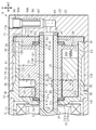
- FIG. 4 is a cross-sectional view taken along the line 6-6 of FIG.
- FIG. 4 is a cross-sectional view taken along the line 7-7 of FIG.
- FIG. 2 is an enlarged cross-sectional view around a front boundary portion and a front chamfered portion in the compressor shown in FIG. FIG.
- FIG. 2 is an enlarged cross-sectional view around a rear boundary portion and a rear chamfered portion in the compressor shown in FIG.
- FIG. 11 is a cross-sectional view taken along the line 12-12 of FIG.
- FIG. 14 is a development view schematically showing a rotating body, both fixed bodies, and vanes in a different phase from FIG. 13.
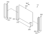
- Perspective view of a rotating body and another vane An exploded perspective view of the vane of FIG. Sectional drawing which shows typically the contact aspect of the vane of FIG. 15 and both fixed body surfaces.
- FIG. 5 is a cross-sectional view schematically showing another example compressor.
- the compressor of the present embodiment is for a vehicle, for example, and is mounted in a vehicle for use.
- the compressor is used, for example, in a vehicle air conditioner, and the fluid to be compressed by the present compressor is a refrigerant containing oil.
- the rotating shaft 12, the rotating body 60, and both fixed bodies 90 and 110 are shown in a side view in FIG.
- a plurality of vanes 131 are schematically shown in a cross-sectional view.
- the compressor 10 includes a housing 11, a rotary shaft 12, an electric motor 13, an inverter 14, a front cylinder 30 that is a cylinder portion, a rear plate 40, a rotating body 60, and a front body.
- a fixed body 90 and a rear fixed body 110 are provided.
- the housing 11 is, for example, tubular as a whole, and has a suction port 11a for sucking a suction fluid from the outside and a discharge port 11b for discharging a compressed fluid.
- the rotating shaft 12, the electric motor 13, the inverter 14, the front cylinder 30, the rear plate 40, the rotating body 60, and both the fixed bodies 90 and 110 are housed in the housing 11.
- the housing 11 includes a front housing member 21, a rear housing member 22, and an inverter cover 25.
- the front housing member 21 has a peripheral wall and an end wall arranged at one end of the peripheral wall in the axial direction, and also has an open end that opens toward the rear housing member 22.
- the suction port 11a is provided, for example, at a position closer to the end wall than the opening end of the peripheral wall of the front housing member 21. However, the position of the suction port 11a is arbitrary.
- the tubular rear housing member 22 has a rear housing end wall 23 and a rear housing peripheral wall 24 extending from the rear housing end wall 23 toward the front housing member 21.
- the front housing member 21 and the rear housing member 22 are united by being joined with their open ends facing each other.
- the discharge port 11b is provided on the peripheral wall 24 of the rear housing. However, the position of the discharge port 11b is arbitrary.
- the inverter cover 25 is arranged on the side opposite to the rear housing member 22 with respect to the front housing member 21.
- the inverter cover 25 is fixed to the front housing member 21 in a state of abutting against the end wall of the front housing member 21.
- the inverter 14 is housed in the inverter cover 25.
- the inverter 14 drives the electric motor 13.
- the front cylinder 30 cooperates with the rear plate 40 to accommodate both the fixed bodies 90 and 110 and the rotating body 60.
- the front cylinder 30 is a tubular body having a diameter smaller than that of the rear housing member 22, and is open toward the rear housing end wall 23.
- the front cylinder 30 has a front cylinder end wall 31 and a front cylinder peripheral wall 32 extending from the front cylinder end wall 31 toward the rear housing end wall 23.
- the front cylinder end wall 31 has a stepped shape in the axial direction Z of the rotary shaft 12, and the first end wall 31 a disposed on the center side and the rotary shaft 12 are arranged. It has a second end wall 31b which is located outside the first end wall 31a in the radial direction R and which is located at a position biased toward the rear housing end wall 23 with respect to the first end wall 31a. ..
- a front insertion hole 31c through which the rotary shaft 12 can be inserted is formed in the first end wall 31a, and the rotary shaft 12 is inserted into the front insertion hole 31c.
- the front cylinder peripheral wall 32 extends inside the rear housing member 22.
- the front cylinder peripheral wall 32 has a front cylinder inner peripheral surface 33 and a front cylinder outer peripheral surface 34 arranged on the side opposite to the front cylinder inner peripheral surface 33.
- the front cylinder inner peripheral surface 33 and the front cylinder outer peripheral surface 34 are, for example, cylindrical surfaces having an axis extending in the axial direction Z of the rotary shaft 12.
- the outer peripheral surface 34 of the front cylinder is in contact with the inner peripheral surface of the peripheral wall 24 of the rear housing in the radial direction R.
- a discharge recess 35 for partitioning the discharge chamber A1 is formed on the outer peripheral surface 34 of the front cylinder.
- the discharge recess 35 is formed between both ends in the axial direction of the outer peripheral surface 34 of the front cylinder, and is recessed inward in the radial direction.
- the discharge recess 35 and the rear housing peripheral wall 24 define a discharge chamber A1 in which the compressed fluid exists.
- the discharge chamber A1 is a cylindrical space having an axis extending in the axial direction Z of the rotary shaft 12.
- the discharge chamber A1 communicates with the discharge port 11b.
- the compressed fluid in the discharge chamber A1 is discharged from the discharge port 11b.
- the front cylinder 30 has a bulging portion 36 that projects radially outward.
- the bulging portion 36 is provided at a position straddling both the front cylinder end wall 31 and the front cylinder peripheral wall 32.
- the bulging portion 36 bulges radially outward from the outer peripheral surface 34 of the front cylinder.
- the front housing member 21 and the rear housing member 22 are connected to each other with the bulging portion 36 interposed therebetween. Both housing members 21 and 22 regulate the displacement of the front cylinder 30 in the axial direction Z.
- a motor chamber A2 partitioned by a front housing member 21 and a front cylinder end wall 31 is provided in the housing 11, and the electric motor 13 is housed in the motor chamber A2.
- the electric motor 13 is supplied with drive power from the inverter 14 to rotate the rotary shaft 12 in a direction indicated by an arrow M, specifically, in a clockwise direction when the two fixed bodies 90 and 110 are viewed from the electric motor 13. Let me.
- the motor chamber A2 is a suction chamber into which the fluid is sucked.
- the inverter 14, the electric motor 13, the front fixed body 90, the rotating body 60, and the rear fixed body 110 are arranged in this order in the axial direction Z.
- the positions of these components are arbitrary, and for example, the inverter 14 may be arranged radially outside the electric motor 13.
- the rear plate 40 has a plate shape (a disk shape in this embodiment), and is housed in the rear housing member 22 so that the plate thickness direction thereof coincides with the axial direction Z.
- the outer diameter of the rear plate 40 is the same as the diameter of the front cylinder outer peripheral surface 34 (or the inner peripheral surface of the rear housing peripheral wall 24), for example.
- the rear plate 40 is fitted in the rear housing member 22 and is supported by the rear housing member 22.
- the rear plate 40 is separate from the front cylinder end wall 31 of the front cylinder 30.
- the front cylinder 30 and the rear plate 40 are assembled so that the tip end (opening end) of the front cylinder peripheral wall 32 abuts against the rear plate 40, and the rear plate 40 closes the opening portion of the front cylinder 30. ing.
- a plate recess 42 is formed in the rear plate 40 at a position facing the front end portion of the front cylinder peripheral wall 32 in the axial direction Z.
- the plate recess 42 is formed over the entire circumference.
- the front cylinder 30 and the rear plate 40 are attached to each other with the tip of the front cylinder peripheral wall 32 fitted in the plate recess 42.
- the rear plate 40 is supported by the housing 11. More specifically, the rear plate 40 is sandwiched between the front cylinder 30 supported by the housing 11 and the rear housing end wall 23 which is a part of the housing 11.
- the rear plate 40 may be supported by the housing 11, and the specific support mode thereof is arbitrary.
- the rear plate 40 has a first plate surface 43 and a second plate surface 44, which are plate surfaces orthogonal to the axial direction Z.
- the first plate surface 43 faces the side opposite to the rear housing end wall 23.
- the second plate surface 44 faces the rear housing end wall 23 in the axial direction Z.
- the first plate surface 43 is smaller than the second plate surface 44.
- opposite means a mode in which two members face each other through a gap and a mode in which the two members are in contact with each other, as long as there is no special description, within a technically consistent range. Including.
- the second plate surface 44 and the rear housing end wall 23 may be separated from each other or may be in contact with each other.
- opposing includes a mode in which two surfaces facing each other are in contact with each other at one part and are apart from each other at the other part.
- the compressor 10 includes shaft bearings 51 and 53 that rotatably support the rotating shaft 12.
- the front shaft bearing 51 is attached to a boss portion 52 provided on the end wall of the front housing member 21.
- the boss portion 52 has a ring shape protruding from the end wall of the front housing member 21.
- the front shaft bearing 51 is arranged radially inward of the boss portion 52, and rotatably supports the front shaft end portion 12a of both shaft end portions 12a and 12b which are both axial end portions of the rotary shaft 12. doing.
- a rear insertion hole 41 through which the rotary shaft 12 is inserted is formed in the center of the rear plate 40.
- the diameter of the rear insertion hole 41 is the same as or larger than the diameter of the rear shaft end portion 12b.
- the rear shaft end portion 12b is inserted into the rear insertion hole 41.
- the rear shaft bearing 53 is provided on the inner wall surface of the rear insertion hole 41 and rotatably supports the rear shaft end 12b.
- the rear shaft bearing 53 is, for example, a coating bearing composed of a coating layer formed on the inner wall surface of the rear insertion hole 41.
- the coating layer is arbitrary, and may be, for example, a layer containing a thermosetting resin or a lubricant.
- the rear shaft bearing 53 is not limited to the coated bearing formed from the coating layer, and may be any, for example, another sliding bearing or a rolling bearing. Note that, in FIG. 1 and the like, the rear shaft bearing 53 is shown thicker than it actually is.
- both shaft ends 12a and 12b are rotatably supported by both shaft bearings 51 and 53.
- the front shaft bearing 51 is attached to the boss portion 52 of the front housing member 21 and that the rear plate 40 having the rear shaft bearing 53 is supported by the rear housing member 22, It can be said that the shaft 12 is rotatably supported by the housing 11 by the both shaft bearings 51 and 53.
- the rotating shaft 12 is cylindrical.
- the rear housing end wall 23 has a housing recess 54 at a position facing the rotating shaft 12 in the axial direction Z.
- the housing recess 54 is, for example, a circular recess that is slightly larger than the rear shaft end 12b. A part of the rear shaft end portion 12b enters into the housing recess 54.
- the compressor 10 includes a ring plate 55 provided in the housing recess 54, and the ring plate 55 regulates the displacement of the rotating shaft 12 in the axial direction Z.
- the ring plate 55 is, for example, a flat plate ring having the same outer diameter as the inner diameter of the housing recess 54, and is fitted in the housing recess 54.
- the ring plate 55 is provided between the rear shaft end portion 12b and the bottom surface of the housing recess 54.
- a portion of the rotary shaft 12 excluding the front shaft end 12 a is sandwiched by the front shaft bearing 51 and the ring plate 55 in the axial direction Z.
- a slight gap may be formed between the ring plate 55 and the rear shaft end portion 12b.
- a housing chamber A3 defined by a front cylinder 30 and a rear plate 40 is formed in the housing 11, and the rotating body 60 and both fixed bodies 90 and 110 are housed in the housing chamber A3. It is contained.
- the motor chamber A2 and the accommodation chamber A3 are arranged in the housing 11 in the axial direction Z.
- the motor chamber A2 and the accommodation chamber A3 are partitioned by the front cylinder end wall 31 so that the fluid in the motor chamber A2 does not flow into the accommodation chamber A3.
- the front cylinder end wall 31 is a partition wall portion that partitions the motor chamber A2 and the storage chamber A3 so that the fluid in the motor chamber A2 does not easily flow into the storage chamber A3.
- the rotating shaft 12 is arranged over both the motor chamber A2 and the accommodating chamber A3 by penetrating the front cylinder end wall 31 which is a partition wall portion.
- the rear plate 40 is a compartment used to partition the containment chamber A3.
- the rotating body 60 will be described in detail with reference to FIGS. 2 to 5.
- the rotating body 60 shown in FIG. 5 is shown in a state in which it is arranged at a rotation position different from that in FIG. 4, that is, in a different phase.
- the rotating body 60 rotates in the rotation direction M with the rotation of the rotating shaft 12.
- the rotating body 60 is arranged in the housing 11 so that its rotation center axis coincides with the center axis of the rotation shaft 12. That is, the rotating body 60 is arranged so as to be coaxial with the rotating shaft 12. Therefore, the compressor 10 has a structure that performs axial movement instead of eccentric movement.
- the rotating body 60 includes a rotating body tubular portion 61 having the rotary shaft 12 inserted therethrough, and a rotating body ring portion 70 extending radially outward from the rotating body tubular portion 61.
- the rotary body cylinder portion 61 is attached to the rotary shaft 12 so as to rotate integrally with the rotary shaft 12. As a result, the rotary body 60 rotates as the rotary shaft 12 rotates.
- the mounting mode of the rotating body cylinder 61 with respect to the rotating shaft 12 is arbitrary.
- the rotating body cylinder 61 may be fixed to the rotating shaft 12 by press fitting, or straddles the rotating shaft 12 and the rotating body 61.
- the rotating body cylinder portion 61 may be fixed to the rotating shaft 12 by a fixing pin that is inserted as a result.
- the rotating body cylinder portion 61 and the rotating shaft 12 may be connected by a connecting member such as a key, or the rotating body cylinder portion 61 and the rotating shaft 12 may be provided in the recess provided in one of the other portions.
- the protrusions may be joined by engaging.
- the rotating body cylinder portion 61 is, for example, a cylindrical body having an axis extending in the axial direction Z.
- the rotating body cylinder portion 61 has an inner diameter that is the same as or larger than the diameter of the rotating shaft 12, for example.
- the inner peripheral surface of the rotating body tubular portion 61 and the outer peripheral surface of the rotating shaft 12 face each other in the radial direction R.
- the rotating body cylinder portion 61 has a cylinder portion outer peripheral surface 62 having an axis extending in the axial direction Z.
- the cylindrical outer peripheral surface 62 is curved so as to be convex outward in the radial direction, and is a cylindrical surface in the present embodiment.
- the rotary body ring portion 70 has a predetermined position between the rotary body end portions 61a and 61b, which are axially opposite ends of the rotary body cylinder portion 61 (near the central portion in the present embodiment). It is provided in.
- the rotating body ring portion 70 is an annular plate-shaped member having a plate thickness in the axial direction Z, and has both axial end surfaces, that is, a front rotating body surface 71 and a rear rotating body surface 72. Both rotating body surfaces 71 and 72 have a ring shape. Both rotating body surfaces 71 and 72 intersect with respect to the axial direction Z, and in the present embodiment, they are flat surfaces orthogonal to the axial direction Z. Therefore, the inner peripheral edge and the outer peripheral edge of each of the rotating body surfaces 71, 72 are linear when viewed from the radial direction R, and the position in the axial direction Z is constant over the entire circumferential direction.
- the ring outer peripheral surface 73 which is the outer peripheral surface of the rotating body ring portion 70, is a surface that intersects the radial direction R and faces the front cylinder inner peripheral surface 33 in the radial direction R.
- the ring outer peripheral surface 73 and the front cylinder inner peripheral surface 33 may be in contact with each other, or may be separated from each other via a minute gap.
- the compressor 10 includes thrust bearings 81 and 82 that support the rotating body 60 in the axial direction Z. Both thrust bearings 81 and 82 are arranged on both sides of the rotating body cylinder portion 61 in the axial direction, and sandwich the rotating body cylinder portion 61 from the axial direction Z.
- the front thrust bearing 81 is arranged in the space created by the step-like formation of the front cylinder end wall 31.
- the front thrust bearing 81 supports the rotating body cylinder portion 61 (specifically, the front rotating body end portion 61a) in the axial direction Z while being supported by the front cylinder end wall 31.
- the rear thrust bearing 82 is arranged in a thrust accommodating recess 83 formed in the rear plate 40.
- the thrust accommodating recess 83 is formed in a portion of the inner wall surface of the rear insertion hole 41 close to the first plate surface 43.
- the rear thrust bearing 82 supports the rotating body cylinder portion 61 (specifically, the rear rotating body end portion 61b) in the axial direction Z while being supported by the rear plate 40.
- Both thrust bearings 81 and 82 are disk-shaped, and the rotary shaft 12 is inserted into both thrust bearings 81 and 82.
- the inner peripheral surfaces of the thrust bearings 81 and 82 and the outer peripheral surface of the rotary shaft 12 are in contact with each other. Therefore, both thrust bearings 81 and 82 support the rotating shaft 12 by abutting the rotating shaft 12 in the radial direction R.
- both thrust bearings 81 and 82 may be separated from the rotating shaft 12 in the radial direction R.
- Both fixed bodies 90 and 110 are arranged on both sides of the rotating body ring portion 70 in the axial direction.
- the two fixed bodies 90 and 110 are arranged so as to be separated from each other in the axial direction Z with the rotating body ring portion 70 being arranged therebetween, or the rotating body ring portion 70 is arranged to be the both fixed bodies. It is arranged between 90 and 110.
- Both fixed bodies 90 and 110 are fixed to the front cylinder 30 (in other words, the housing 11) so as not to rotate with the rotation of the rotating shaft 12.
- the fixed bodies 90 and 110 are fixed to the front cylinder 30 by fastening the front cylinder peripheral wall 32 and the fixed bodies 90 and 110 using a fastener (not shown) that penetrates the front cylinder peripheral wall 32.
- the present invention is not limited to this, and the fixing mode of both fixed bodies 90 and 110 to the front cylinder 30 is arbitrary, and the fixing mode may be, for example, press fitting or fitting. Further, one or a plurality of fastening portions for fastening the front fixed body 90 and the front cylinder end wall 31 may be provided, and one or a plurality of fastening portions for fastening the rear fixed body 110 and the rear plate 40 may be provided. It may be provided.
- both fixed bodies 90 and 110 have the same shape.
- the front fixing body 90 arranged at a position close to the front cylinder end wall 31 of both fixing bodies 90 and 110, in other words, a position close to the motor chamber A2 is, for example, a ring. It has a shape (annular shape in this embodiment) and has a front fixed body insertion hole 91 into which the rotary shaft 12 is inserted.
- the front fixed body insertion hole 91 is a through hole that penetrates the front fixed body 90 in the axial direction Z.
- the front fixed body 90 is arranged in the front cylinder 30 with the rotating shaft 12 inserted into the front fixed body insertion hole 91.
- the front fixed body 90 has a front cylinder inner peripheral surface 33 and a front fixed body outer peripheral surface 92 facing the radial direction R.
- the outer peripheral surface 92 of the front fixed body and the inner peripheral surface 33 of the front cylinder are in contact with each other.
- the present invention is not limited to this, and the inner peripheral surface 33 of the front cylinder and the outer peripheral surface 92 of the front fixed body may be separated from each other.
- the front fixed body 90 includes a front cylinder end wall 31 and a front rear surface 93 that faces the axial direction Z.
- the front back surface 93 and the inner bottom surface 31d of the front cylinder end wall 31 may be separated from each other or may be in contact with each other.
- the rear fixing body 110 arranged at a position close to the rear plate 40, which is a partition of the two fixing bodies 90 and 110, in other words, at a position distant from the motor chamber A2, Like the front fixed body 90, it has a ring shape (annular shape in this embodiment) and has a rear fixed body insertion hole 111 into which the rotating shaft 12 is inserted.
- the rear fixed body insertion hole 111 is a through hole that penetrates the rear fixed body 110 in the axial direction Z.
- the rear fixed body 110 is arranged in the front cylinder 30 with the rotating shaft 12 inserted into the rear fixed body insertion hole 111. That is, in this embodiment, the rotary shaft 12 penetrates both the fixed bodies 90 and 110 in the axial direction Z.
- the rear fixed body 110 has a front cylinder inner peripheral surface 33 and a rear fixed body outer peripheral surface 112 facing the radial direction R.
- the outer peripheral surface 112 of the rear fixed body and the inner peripheral surface 33 of the front cylinder are in contact with each other.
- the present invention is not limited to this, and the inner peripheral surface 33 of the front cylinder and the outer peripheral surface 112 of the rear fixed body may be separated from each other.
- the rear fixed body 110 includes a first plate surface 43 of the rear plate 40 and a rear back surface 113 facing the axial direction Z.
- the rear back surface 113 and the first plate surface 43 may be separated from each other or may be in contact with each other.
- the rotating body 60 is supported by the fixed bodies 90 and 110 by inserting the rotating body cylinder portion 61 into the fixed body insertion holes 91 and 111.
- the front rotating body end 61a of the rotating body cylinder 61 is inserted into the front fixing body insertion hole 91 and penetrates the front fixing body 90.
- the front fixed body insertion hole 91 has a shape and size corresponding to the rotary body tubular portion 61 (specifically, the tubular portion outer peripheral surface 62).
- the front fixed body insertion hole 91 corresponds to the cylindrical rotating body tubular portion 61 and is circular when viewed from the axial direction Z.
- the diameter of the front fixed body insertion hole 91 is the same as or slightly larger than the diameter of the outer peripheral surface 62 of the tubular portion.
- the front rotating body end 61a is rotatably supported by the front fixing body 90 by the front rotating body bearing 94 formed on the inner wall surface of the front fixing body insertion hole 91.
- the rear rotary body end portion 61b is inserted into the rear fixed body insertion hole 111 and penetrates the rear fixed body 110.
- the rear fixed body insertion hole 111 has a shape and size corresponding to the rotary body tubular portion 61 (specifically, the tubular portion outer peripheral surface 62).
- the rear fixed body insertion hole 111 has a circular shape when viewed in the axial direction Z, corresponding to the cylindrical rotating body tubular portion 61.
- the diameter of the rear fixed body insertion hole 111 is the same as or slightly larger than the diameter of the cylindrical outer peripheral surface 62.
- the rear rotating body end portion 61b is rotatably supported by the rear fixed body 110 by the rear rotating body bearing 114 formed on the inner wall surface of the rear fixed body insertion hole 111.
- both rotary body end portions 61a, 61b are supported by the both fixed bodies 90, 110 via the both rotary body bearings 94, 114.
- the rotating body 60 is supported by both the fixed bodies 90 and 110, and the positional deviation of the rotating body 60 with respect to the both fixed bodies 90 and 110 can be suppressed.
- both rotary body end portions 61a and 61b constitute both axial end portions of the rotary body 60. Therefore, both end portions of the rotating body 60 in the axial direction are supported by the rotating body bearings 94 and 114. As a result, the rotating body 60 is stably held.
- the fixed body insertion holes 91 and 111 are formed so as to correspond to the rotary body cylinder portion 61, a gap formed between the inner wall surface of the fixed body insertion holes 91 and 111 and the cylindrical portion outer peripheral surface 62. Is small or such a gap is unlikely to occur.
- the rotary body bearings 94 and 114 are coated bearings formed of a coating layer formed on the inner wall surfaces of the fixed body insertion holes 91 and 111, for example. In FIG. 4 etc., the rotor bearings 94 and 114 are shown thicker than they actually are.
- the specific configurations of the rotating body bearings 94 and 114 are not limited to the coated bearings, and may be arbitrary, for example, other sliding bearings or rolling bearings.
- the front fixed body 90 has a front fixed body surface 100 which is a fixed body surface facing the front rotary body surface 71 in the axial direction Z.
- the front fixed body surface 100 is a plate surface opposite to the front rear surface 93.
- the front fixed body surface 100 has a ring shape, and in the present embodiment, has an annular shape when viewed in the axial direction Z.
- the front fixed body surface 100 connects the first front flat surface 101 and the second front flat surface 102 that intersect the axial direction Z (orthogonal in the present embodiment) and both front flat surfaces 101 and 102. It includes two front curved surfaces 103, which are curved surfaces.
- both front flat surfaces 101 and 102 are displaced in the axial direction Z.
- the second front flat surface 102 which is the fixed body contact surface, is arranged at a position closer to the front rotary body surface 71 than the first front flat surface 101, and contacts the front rotary body surface 71.
- a portion of the front fixed body surface 100 other than the second front flat surface 102 is separated from the front rotary body surface 71.
- Both front flat surfaces 101 and 102 are arranged apart from each other in the circumferential direction of the front fixed body 90, and are displaced from each other by, for example, 180 °.
- both front flat surfaces 101 and 102 are fan-shaped.
- the circumferential positions of both fixed bodies 90 and 110 are also referred to as angular positions.
- the two front curved surfaces 103 are each fan-shaped. As shown in FIG. 3, the two front curved surfaces 103 are arranged so as to face each other in the radial direction when viewed from the axial direction Z. Both front curved surfaces 103 have the same shape.
- Each front curved surface 103 and both front flat surfaces 101 and 102 are connected. More specifically, one of the front curved surfaces 103 connects the first end portions of the front flat surfaces 101 and 102 in the circumferential direction to each other, and the other one of the front flat surfaces 101 and 102 extends in the second direction of the circumferential direction of the front flat surfaces 101 and 102. It connects the ends.
- the angular position of the boundary portion between each front curved surface 103 and the first front flat surface 101 is set as the first angular position ⁇ 1, and the angular position of the boundary portion between each front curved surface 103 and the second front flat surface 102 is the second angle.
- the position is ⁇ 2.
- the respective angular positions ⁇ 1 and ⁇ 2 are shown by broken lines, but in reality, the front curved surface 103 and the front flat surfaces 101 and 102 are smoothly continuous at the boundary portion.
- Each front curved surface 103 is a curved surface in which the position in the axial direction Z changes according to the circumferential position, in other words, the angular position of the front fixed body 90. Specifically, each front curved surface 103 is curved in the axial direction Z so as to gradually approach the front rotary body surface 71 from the first angular position ⁇ 1 toward the second angular position ⁇ 2. In other words, the two front curved surfaces 103 are provided on both sides in the circumferential direction with respect to the second front flat surface 102, and are gradually separated from the front rotary body surface 71 as they are separated from the second front flat surface 102 in the circumferential direction. It is curved in the axial direction Z.
- Each front curved surface 103 is curved in the axial direction Z so as to be concave with respect to the front rotary body surface 71, and is curved in the axial direction Z so as to be convex toward the front rotary body surface 71. It has a front convex surface 103b and the like.
- the front concave surface 103a is arranged closer to the first front flat surface 101 than the second front flat surface 102, and the front convex surface 103b is arranged closer to the second front flat surface 102 than the first front flat surface 101.
- the front concave surface 103a and the front convex surface 103b are connected. That is, the front curved surface 103 is a curved surface having an inflection point.
- the angle range of the front convex surface 103b and the front concave surface 103a may be the same or different. Moreover, the position of the inflection point is arbitrary. Further, since the front curved surface 103 can be said to be a curved surface that is curved in a wavy shape, the front fixed body surface 100 can be said to be a front wave surface that includes a portion that is curved in a wavy shape.
- the rear fixed body 110 has a rear fixed body surface 120 which is a fixed body surface facing the rear rotary body surface 72 in the axial direction Z.
- the rear fixed body surface 120 is a plate surface opposite to the rear rear surface 113.
- the rear fixed body surface 120 has a ring shape when viewed in the axial direction Z, and has an annular shape in the present embodiment.
- the rear fixed body surface 120 has the same shape as the front fixed body surface 100. As shown in FIG. 2, the rear fixed body surface 120 connects the first rear flat surface 121 and the second rear flat surface 122 which intersect with the axial direction Z (orthogonal in the present embodiment) and both rear flat surfaces 121 and 122. It includes two rear curved surfaces 123, which are curved surfaces.
- the rear flat surfaces 121 and 122 are displaced from each other in the axial direction Z.
- the second rear flat surface 122 which is the fixed body contact surface, is arranged at a position closer to the rear rotary body surface 72 than the first rear flat surface 121, and contacts the rear rotary body surface 72. There is. The portion of the rear fixed body surface 120 other than the second rear flat surface 122 is separated from the rear rotary body surface 72.
- Both rear flat surfaces 121, 122 are arranged apart from each other in the circumferential direction of the rear fixed body 110, and are displaced from each other by 180°, for example.
- both rear flat surfaces 121 and 122 are fan-shaped.
- the two rear curved surfaces 123 are each fan-shaped.
- the two rear curved surfaces 123 are arranged so as to face each other in the radial direction when viewed from the axial direction Z.
- One of the rear curved surfaces 123 connects the first end portions of the rear flat surfaces 121 and 122 in the circumferential direction, and the other connects the second end portions of the rear flat surfaces 121 and 122 in the circumferential direction. Are connected.
- the two rear curved surfaces 123 are provided on both sides in the circumferential direction with respect to the second rear flat surface 122, and gradually move away from the rear rotary body surface 72 as they move away from the second rear flat surface 122 in the circumferential direction. It is curved to.
- Both fixed body surfaces 100 and 120 are arranged in a state in which the rotating body ring portion 70 is arranged between them so as to face each other while being separated in the axial direction Z, and the angular positions thereof are deviated from each other by 180°.
- the distance in the axial direction Z between the fixed body surfaces 100 and 120 is constant regardless of its angular position (in other words, circumferential position).
- the first front flat surface 101 and the second rear flat surface 122 are opposed to each other in the axial direction Z, and the second front flat surface 102 and the first rear flat surface 121 are formed. It faces the axial direction Z.
- the amount of deviation in the axial direction Z between the two front flat surfaces 101 and 102 is the same as the amount of deviation in the axial direction Z between the two rear flat surfaces 121 and 122.
- shift amount Z1 the amount of deviation in the axial direction Z between the front flat surfaces 101 and 102 and the amount of deviation in the axial direction Z between the two rear flat surfaces 121 and 122.
- the curved condition of the front curved surface 103 and the curved condition of the rear curved surface 123 are the same. That is, the front curved surface 103 and the rear curved surface 123 are curved in the same manner so that the distance in the axial direction Z does not change according to their angular positions. As a result, the distance in the axial direction Z between the fixed body surfaces 100 and 120 is constant at any angular position.
- the rear curved surface 123 can be said to be a wavy curved surface, and therefore the rear fixed body surface 120 can also be called a rear wavy surface including a wavy portion.
- the circumferential directions of both the fixed bodies 90, 110 and the rotary body 60 coincide with the circumferential direction of the rotary shaft 12, and the radial directions of the fixed bodies 90, 110 and the rotary body 60 coincide with the radial direction R of the rotary shaft 12.
- the axial directions of the fixed bodies 90 and 110 and the rotary body 60 coincide with the axial direction Z of the rotary shaft 12. Therefore, the circumferential direction, radial direction R, and axial direction Z of the rotating shaft 12 may be appropriately read as the circumferential direction, radial direction, and axial direction of the rotating body 60, and the circumferential direction and diameter of both fixed bodies 90 and 110. It may be read as a direction and an axial direction.
- the contact point between the front rotating body surface 71 and the second front flat surface 102 is also referred to as a front contact point Pf.
- the front contact point Pf is fan-shaped like the second front flat surface 102.
- the contact point between the rear rotary body surface 72 and the second rear flat surface 122 is also referred to as a rear contact point Pr.
- the rear contact portion Pr is fan-shaped like the second rear flat surface 122.
- the compressor 10 includes compression chambers A4 and A5 in which fluid is sucked and compressed. Both compression chambers A4 and A5 are provided in the accommodation chamber A3, and are specifically arranged on both sides of the rotating body ring portion 70 in the axial direction Z.
- the front compression chamber A4 is partitioned by a front rotating body surface 71 and a front fixed body surface 100, and more specifically, a front rotating body surface 71, a front fixed body surface 100, a cylinder outer peripheral surface 62, and a front cylinder inner peripheral surface 33. It is partitioned by and.
- the rear compression chamber A5 is partitioned by a rear rotating body surface 72 and a rear fixed body surface 120, and more specifically, a rear rotating body surface 72, a rear fixed body surface 120, a cylinder outer peripheral surface 62, and a front cylinder inner peripheral surface 33. It is partitioned by and. In the present embodiment, the front compression chamber A4 and the rear compression chamber A5 have the same size.
- the front cylinder inner peripheral surface 33 is a cylinder inner peripheral surface that divides the compression chambers A4 and A5 in cooperation with the rotating body surfaces 71 and 72 and the fixed body surfaces 100 and 120.
- the compression chambers A4 and A5 and the discharge chamber A1 are opposed to each other in the radial direction R with the front cylinder peripheral wall 32 arranged between them. That is, the discharge chamber A1 is arranged outside both the compression chambers A4 and A5 in the radial direction R.
- the discharge chamber A1 faces a part of the front compression chamber A4 in the radial direction R, and faces the entire rear compression chamber A5 in the radial direction R, but is not limited to this. ..
- the discharge chamber A1 may extend in the axial direction Z so as to face at least a part of the front compression chamber A4 in the radial direction R and at least a portion of the rear compression chamber A5 in the radial direction R. ..
- the compressor 10 includes a plurality of (three) vane grooves 130 formed in the rotating body 60 and a plurality (three) vanes 131 inserted into the vane grooves 130, respectively. , Is equipped.
- the vane groove 130 is formed in the rotating body ring portion 70.
- the vane groove 130 penetrates the rotating body ring portion 70 in the axial direction Z and opens toward both rotating body surfaces 71 and 72.
- the vane groove 130 has a width in a direction orthogonal to both the axial direction Z and the radial direction R and extends in the radial direction R, and opens outward in the radial direction.
- the vane groove 130 is not formed in the rotating body tubular portion 61.
- the vane groove 130 has a pair of side surfaces facing each other while being spaced apart from each other in the circumferential direction.
- the rotating body ring portion 70 is a portion located on the outer side in the radial direction with respect to the rotating body cylinder portion 61. Therefore, the rotating body cylinder portion 61 exists inside the rotating body ring portion 70 in the radial direction. That is, the rotating body ring portion 70 is a portion that is provided on the outer peripheral surface 62 of the tubular portion and that projects radially outward from the outer peripheral surface 62 of the tubular portion.
- the vane 131 has a rectangular plate shape as a whole, and has a plate surface intersecting (orthogonal) with respect to the circumferential direction of the rotation axis 12.
- the vane 131 is arranged between the two fixed bodies 90 and 110, in other words, between the two fixed body surfaces 100 and 120.
- the vane 131 is a plate-like body having a thickness in the width direction of the vane groove 130, in other words, in a direction orthogonal to both the axial direction Z and the radial direction R.
- Both plate surfaces of the vane 131 and both side surfaces of the vane groove 130 face each other in the circumferential direction (in other words, the width direction of the vane groove 130).
- the width of the vane groove 130 (in other words, the distance between both side surfaces of the vane groove 130) is the same as or slightly wider than the plate thickness of the vane 131.
- the vane 131 inserted into the vane groove 130 is sandwiched by both side surfaces of the vane groove 130.
- the vane 131 is allowed to move axially Z along the vane groove 130.
- the vane 131 specifically, both ends of the vane 131 in the axial direction are in contact with both the fixed body surfaces 100 and 120.
- the plurality of vane grooves 130 are arranged at equal intervals in the circumferential direction, and in detail, they are arranged at positions displaced from each other by 120°.
- a plurality of vanes 131 are arranged at equal intervals in the circumferential direction.
- the vane 131 rotates in the rotation direction M as the rotating body 60 rotates. Then, the vane 131 that is in contact with both the fixed body surfaces 100 and 120 moves (swings) in the axial direction Z along the curved fixed body surfaces 100 and 120. That is, the vane 131 rotates while moving in the axial direction Z. As a result, the vanes 131 enter the front compression chamber A4 and the rear compression chamber A5. That is, the vane groove 130 causes the vane 131 to be arranged in both the compression chambers A4 and A5 while rotating the vane 131 as the rotating body 60 rotates.
- the movement distance (in other words, the swing distance) of the vane 131 in the axial direction Z is the displacement amount in the axial direction Z between the front flat surfaces 101 and 102 (or between the rear flat surfaces 121 and 122), that is, the displacement amount Z1. is there. Further, the vane 131 is continuously in contact with both the fixed body surfaces 100 and 120 during the rotation of the rotating body 60, and intermittent contact, in particular, separation and contact are not likely to be repeated.
- the front compression chamber A4 is divided into three parts chambers, that is, a first front compression chamber A4a, a second front compression chamber A4b, and a third front compression chamber A4c by three vanes 131. ..
- the part chamber located on the leading side with respect to the front contact point Pf (in other words, the second front flat surface 102) in the rotation direction M is the first front compression chamber A4a.
- the parts chamber arranged on the trailing side of the first front compression chamber A4a in the rotation direction M is referred to as the second front compression chamber A4b. At least a part of the second front compression chamber A4b is arranged on the trailing side with respect to the front contact point Pf in the rotation direction M.
- the parts chamber located between the first front compression chamber A4a and the second front compression chamber A4b in the circumferential direction is referred to as the third front compression chamber A4c.
- the third front compression chamber A4c is arranged on the leading side of the first front compression chamber A4a and on the trailing side of the second front compression chamber A4b in the rotation direction M.
- the "leading side in the rotation direction M” and the “successor side in the rotation direction M” may be simply referred to as the “leading side” and the “successor side”, respectively.
- Each front compression chamber A4a to A4c is formed over an angle range of 120 °. That is, each of the front compression chambers A4a to A4c extends in the circumferential direction, and the length in the circumferential direction corresponds to an angle range of 120 °.
- the vanes 131 when one of the plurality of vanes 131 is in contact with the second front flat surface 102, the vanes 131 have not entered the front compression chamber A4. In this case, the spaces on both sides of the vane 131 in contact with the second front flat surface 102 in the circumferential direction are partitioned by the front contact points Pf to block mutual communication. Therefore, even when one of the plurality of vanes 131 is in contact with the second front flat surface 102, the front compression chamber A4 is divided into three parts chambers.
- the front compression chamber A4 is formed by the three vanes 131 in the front compression chambers A4a to A4a. It is assumed to be partitioned into A4c.
- the rear compression chamber A5 is arranged on the trailing side with respect to the first rear compression chamber A5a and the first rear compression chamber A5a by the three vanes 131. It is partitioned into a second rear compression chamber A5b and a third rear compression chamber A5c arranged on the leading side with respect to the first rear compression chamber A5a.
- the first rear compression chamber A5a, the second rear compression chamber A5b, and the third rear compression chamber A5c are similar to the first front compression chamber A4a, the second front compression chamber A4b, and the third front compression chamber A4c. The description is omitted.
- the compressor 10 includes a front suction port 141 through which a fluid sucked into the front compression chamber A4 passes.
- the front intake port 141 is formed in, for example, the front cylinder 30, and specifically, extends in the axial direction Z over both the front cylinder end wall 31 and the front cylinder peripheral wall 32.
- the front suction port 141 extends in the circumferential direction along the peripheral wall 32 of the front cylinder, and is formed in an arc shape when viewed from the axial direction Z. At least a part of the front suction port 141 is arranged radially outward with respect to the first front compression chamber A4a. In other words, the first front compression chamber A4a includes a part or all of the space inside the front suction port 141 in the radial direction.
- the front intake port 141 is open to the motor chamber A2 and the front compression chamber A4.
- the motor chamber A2 and the front compression chamber A4 are communicated with each other by the front suction port 141.
- the front intake port 141 has a front intake opening 141a that is open at a position communicating with the first front compression chamber A4a.
- the front intake opening 141a extends in the rotational direction M from a position corresponding to the circumferential center of the second front flat surface 102 of the front cylinder inner circumferential surface 33.
- the extended length of the front suction opening 141a may be substantially the same as, for example, the circumferential length of each of the front compression chambers A4a to A4c.
- the front suction opening 141a extends in the circumferential direction from a position corresponding to the central portion in the circumferential direction of the second front flat surface 102 of the inner peripheral surface 33 of the front cylinder by substantially the same length as the circumferential interval of the vane 131. May be.
- the angular position of the central portion in the circumferential direction of the second front flat surface 102 is set to 0°, and the angle increases from the angular position of 0° in the rotation direction M.
- the front intake opening 141a is preferably formed, for example, at least over a range from the leading end of the second front flat surface 102 in the rotation direction M to an angular position of 120°.
- the compressor 10 has a plurality of front discharge ports 151 which are discharge passages for discharging the fluid compressed in the front compression chamber A4, and a front valve 152 for opening and closing the front discharge port 151. And a front retainer 153 that defines the maximum opening degree of the front valve 152.
- the front discharge port 151 is provided in the front cylinder 30, for example. Specifically, the front discharge port 151 is provided in the front cylinder peripheral wall 32 at a position on the radial outer side of the front compression chamber A4 and on the trailing side with respect to the front contact portion Pf.
- the curved front cylinder outer peripheral surface 34 has a front seating surface 154 recessed from the front cylinder outer peripheral surface 34.
- the front seat surface 154 is formed in a portion of the outer peripheral surface 34 of the front cylinder between the front compression chamber A4 and the discharge chamber A1 and on the side following the front contact portion Pf.
- the front seat surface 154 is a flat surface orthogonal to the radial direction R.
- the front discharge port 151 is provided on the front seat surface 154.
- the front discharge port 151 communicates the second front compression chamber A4b with the discharge chamber A1 by penetrating the peripheral wall 32 of the front cylinder.
- the multiple front discharge ports 151 are arranged in the circumferential direction.
- Each of the plurality of front discharge ports 151 has a circular shape.
- the number and shape of the front discharge ports 151 are arbitrary.
- the number of front discharge ports 151 may be one.
- the front discharge port 151 may have an oval shape or the like.
- the sizes of the front discharge ports 151 may be the same or different.
- At least a part of the front discharge port 151 is arranged radially outside of the second front compression chamber A4b.
- the second front compression chamber A4b includes a part or all of the space inside the front discharge port 151 in the radial direction.
- the front suction port 141 and the front discharge port 151 are separated from each other in the circumferential direction in a state where the radial outer portion of the front contact portion Pf of the front cylinder peripheral wall 32 is arranged between them.
- the first front compression chamber A4a is configured so as to communicate with the front intake port 141 but not with the front discharge port 151.
- the second front compression chamber A4b communicates with the front discharge port 151.
- the second front compression chamber A4b may move in the radial direction of the front suction port 141 depending on the angular position of the vane 131. It may be arranged so as to straddle both the inside and the radial inside of the front discharge port 151.
- the front contact point Pf exists between the space radially inside the front suction port 141 and the space radially inside the front discharge port 151.
- the front contact point Pf blocks the communication between the two spaces from each other. Therefore, the communication between the front suction port 141 and the front discharge port 151 is restricted. That is, the second front compression chamber A4b may be further partitioned into a space where suction is performed and a space where compression is performed by the front contact portion Pf.
- the third front compression chamber A4c shifts from the state in which it does not communicate with the front discharge port 151 to the state in which it communicates with the front discharge port 151 as the rotor 60 rotates.
- the front valve 152 and the front retainer 153 are provided on the front seat surface 154.
- the front bearing surface 154 has a screw hole 154a.
- the front valve 152 and the front retainer 153 are fixed to the front seat surface 154 by screwing bolts B penetrating both the front valve 152 and the front retainer 153 into the screw holes 154a.
- the front valve 152 normally closes the front discharge port 151.
- the pressure of the front compression chamber A4 (specifically, the second front compression chamber A4b) exceeds the threshold value, the front valve 152 shifts from the state of closing the front discharge port 151 to the state of opening the front discharge port 151.
- the opening angle of the front valve 152 is regulated by the front retainer 153.
- the compressor 10 includes a rear suction port 142 through which a fluid sucked into the rear compression chamber A5 passes.
- the rear suction port 142 is formed in, for example, the front cylinder 30, and specifically, extends in the axial direction Z over both the front cylinder end wall 31 and the front cylinder peripheral wall 32.
- the rear suction port 142 extends in the circumferential direction along the peripheral wall 32 of the front cylinder, and is formed in an arc shape when viewed from the axial direction Z. At least a part of the rear intake port 142 is arranged radially outside of the first rear compression chamber A5a. In other words, the first rear compression chamber A5a includes a part or all of the space radially inside the rear suction port 142.
- the rear suction port 142 is open to the motor chamber A2 and also to the rear compression chamber A5.
- the motor chamber A2 and the rear compression chamber A5 are communicated with each other by the rear suction port 142.
- the rear suction port 142 has a rear suction opening 142a opened at a position communicating with the first rear compression chamber A5a.
- the rear suction opening 142a extends in the rotational direction M from a position corresponding to the circumferential center of the second rear flat surface 122 of the front cylinder inner circumferential surface 33.
- the rear suction port 142 and the rear suction opening 142a are rotated in the rotation direction within a range that does not interfere with the front discharge port 151, the front valve 152, and the front retainer 153 from the position corresponding to the circumferential center of the second rear flat surface 122. It extends to M.
- the circumferential lengths of the rear suction port 142 and the rear suction opening 142a may be the same as the circumferential lengths of the front suction port 141 and the front suction opening 141a.
- the axial length of the front valve 152 or the like is shortened or the position of the front discharge port 151 is shifted so that the rear suction port 142 and the rear suction opening 142a do not interfere with the front discharge port 151 or the like.
- the angle range of the second front flat surface 102 may be narrowed.
- two suction ports 141, 142 are provided corresponding to the two compression chambers A4, A5.
- the front suction port 141 and the rear suction port 142 are arranged so as to be displaced from each other in the circumferential direction so as not to communicate with each other, and in detail, they are arranged at positions shifted from each other by 180 °.
- the suction amount of the fluid into one of the compression chambers A4 and A5 reduces the suction amount of the fluid into the other compression chamber, so that the suction ports 141 and 142 communicate with each other. It is possible to suppress the inconvenience caused by the presence of
- the compressor 10 includes a plurality of rear discharge ports 161 which are discharge passages for discharging the fluid compressed in the rear compression chamber A5, a rear valve 162 for opening and closing the rear discharge port 161 and a rear. And a rear retainer 163 that regulates the maximum opening of the valve 162.
- the rear discharge port 161 is provided, for example, in the front cylinder 30. Specifically, the rear discharge port 161 is provided in the front cylinder peripheral wall 32 at a position on the radial outer side of the rear compression chamber A5 and on the trailing side with respect to the second rear flat surface 122.
- the rear discharge port 161 is formed at a position shifted by 180° in the circumferential direction with respect to the front discharge port 151. Has been done. Further, the rear discharge port 161 is displaced from the front discharge port 151 in the axial direction Z in correspondence with the front compression chamber A4 and the rear compression chamber A5 being arranged to be displaced from each other in the axial direction Z. ..
- the specific configurations of the rear discharge port 161, the rear valve 162, and the rear retainer 163 are basically the same as the front discharge port 151, the front valve 152, and the front retainer 153, except that the positions where they are provided are different. Therefore, detailed description is omitted. Further, "front” in the description of the front discharge port 151, the front valve 152 and the front retainer 153 described above may be read as "rear”.
- the fluid is always sucked in the space on the leading side of the front contact point Pf.
- the fluid is always compressed in the space following the front contact portion Pf. That is, the front compression chamber A4 is provided on the front side of the front contact point Pf, is provided on the suction space Sf1 in which the fluid is sucked, and is provided on the rear side of the front contact point Pf, and compresses the fluid. And a compression space Sf2 in which is performed.
- the suction space Sf1 is composed of the first front compression chamber A4a when the vane 131 is in contact with the second front flat surface 102, and the vane 131 is in contact with the second front flat surface 102.
- the second front compression chamber A4b is constituted by a space on the leading side of the front contact portion Pf.
- the suction space Sf1 communicates with the front suction port 141, and the volume of the suction space Sf1 increases as the vane 131 rotates.
- the suctioned fluid exists in the suction space Sf1.
- the compression space Sf2 is composed of the second front compression chamber A4b, and more specifically, is the space of the second front compression chamber A4b on the subsequent side of the front contact point Pf.
- the compression space Sf2 is a space surrounded by the vanes 131 partitioning the second front compression chamber A4b and the third front compression chamber A4c from each other and the front contact point Pf.
- the volume of the compression space Sf2 decreases as the vane 131 rotates.
- the front discharge port 151 discharges the compressed fluid in the compression space Sf2 by communicating with the compression space Sf2.
- the compression space Sf2 and the suction space Sf1 are blocked from mutual communication by the front contact portion Pf.
- the front contact portion Pf functions as a sealing portion that regulates the movement of the fluid from the compression space Sf2 to the suction space Sf1.
- the second front flat surface 102 is arranged at both ends in the circumferential direction in the compression space Sf2. It can be said that it has one contact surface end portion 102a and a second contact surface end portion 102b arranged in the suction space Sf1.
- the first contact surface end portion 102 a is a trailing end portion of both ends in the circumferential direction of the second front flat surface 102
- the second contact surface end portion 102 b is in the circumferential direction of the second front flat surface 102. It is the leading end of both ends.
- the rear compression chamber A5 is provided on the front side with respect to the rear contact point Pr, and the suction space Sr1 for sucking fluid and the rear side with respect to the rear contact point Pr.
- a compression space Sr2 which is provided for the compression of the fluid.
- the rear contact point Pr regulates leakage of the compressed fluid from the compression space Sr2 to the suction space Sr1. Since the specific configurations of the suction space Sr1 and the compression space Sr2 are the same as those of the suction space Sf1 and the compression space Sf2, detailed description thereof will be omitted.
- the compressor 10 includes an oil separator 166.
- the compressed fluid is introduced into the oil separator 166 from the discharge chamber A1 through the passage 165 formed in the housing 11.
- the oil separator 166 separates oil contained in the compressed fluid.
- the oil separator 166 is provided on the rear housing member 22, specifically, the rear housing end wall 23.
- the oil separator 166 extends in one direction orthogonal to the axial direction Z, for example, in the vertical direction.
- the oil separator 166 is not limited to the structure extending in the vertical direction, and may be inclined with respect to the vertical direction.
- the oil separator 166 includes an oil separation chamber 167 and an oil separation cylinder 168 arranged in the oil separation chamber 167.
- the oil separation chamber 167 is a cylindrical space extending in the direction orthogonal to the axial direction Z.
- the oil separation chamber 167 extends in the radial direction R and opens upward.
- the opening of the oil separation chamber 167 constitutes the discharge port 11b.
- the oil separation cylinder 168 has a large-diameter cylinder portion 168a and a small-diameter cylinder portion 168b having a smaller diameter than the large-diameter cylinder portion 168a.
- the small-diameter cylindrical portion 168b is provided at a position facing the passage 165 in the axial direction Z.
- the compressed fluid in the discharge chamber A1 flows out to the oil separation chamber 167 via the passage 165.
- the compressed fluid that has flown into the oil separation chamber 167 is sprayed onto the outer peripheral surface of the small diameter cylindrical portion 168b of the oil separation cylinder 168, and is guided below the oil separation chamber 167 while swirling around the small diameter cylindrical portion 168b.
- the centrifugal force acting on the compressed fluid separates the oil from the compressed fluid.
- the oil separated from the compressed fluid flows down below the oil separation chamber 167.
- the compressed fluid from which the oil has been separated by swirling around the small diameter cylinder portion 168b flows into the oil separation cylinder 168 from the lower opening of the oil separation cylinder 168 (small diameter cylinder portion 168b).
- the compressed fluid that has flowed into the oil separation cylinder 168 is discharged from the discharge port 11b.
- the compressor 10 includes an oil storage chamber A6 that stores the oil separated by the oil separator 166.
- the oil storage chamber A6 is provided in the rear housing end wall 23 at a portion radially inward of the oil separator 166.
- the oil storage chamber A6 faces the rotating shaft 12 in the axial direction Z.
- the oil separated by the oil separator 166 flows down toward the oil storage chamber A6 and is stored in the oil storage chamber A6.
- the specific shape and arrangement of the passage 165 and the oil storage chamber A6 are arbitrary. Further, the discharge chamber A1 may be extended in the axial direction Z so that the discharge chamber A1 directly communicates with the oil separator 166 without passing through the passage 165.
- the boundary portion between the rotating body tubular portion 61 and the rotating body ring portion 70 is formed in a non-rectangular shape, for example, curved.
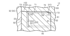
- the front boundary portion 171 that is a boundary portion between the outer peripheral surface 62 of the cylinder portion and the front surface 71 of the rotating body is formed in a non-rectangular shape, and is curved, for example.
- the front boundary portion 171 is curved in an arc shape in cross section.
- the front boundary portion 171 curved in an arcuate cross section is formed over the entire circumferential direction.
- a corner portion between the front fixed body surface 100 including the second front flat surface 102 and the inner wall surface of the front fixed body insertion hole 91 is chamfered. More specifically, a front chamfered portion 172 is formed in a corner portion between the front fixed body surface 100 including the second front flat surface 102 and the inner wall surface of the front fixed body insertion hole 91.
- the front chamfered portion 172 faces the front boundary portion 171. As shown in FIG. 6, the front chamfered portion 172 is formed over the entire circumferential direction, and has an annular shape when viewed from the axial direction Z.
- the front chamfer 172 forms a front chamfer space Sf3 between the front boundary 171 and the front chamfer 172 so that the front boundary 171 and the front fixed body 90 do not interfere with each other. That is, the front chamfered portion 172 is a relief portion that avoids interference with the front boundary portion 171.
- the rear boundary portion 173 which is the boundary portion between the outer peripheral surface 62 of the tubular portion and the rear rotating body surface 72, is curved in a circular arc shape, for example.
- a rear chamfer 174 is formed at a position facing the rear boundary 173 of the rear fixed body 110.
- a rear chamfered space Sr3 is formed between the rear boundary portion 173 and the rear chamfered portion 174.
- the compressor 10 has a configuration for improving the sealing performance of both contact points Pf and Pr.
- the configuration will be described in detail below. Since the structure for improving the sealing property of the front contact point Pf and the structure for improving the sealing property of the rear contact point Pr are basically the same, basically the sealing property of the front contact point Pf is A configuration for increasing the sealing property of the rear contact portion Pr will be described, and a detailed description thereof will be omitted.
- the compressor 10 includes an oil supply passage 180 that supplies oil to the front contact point Pf.
- the oil supply passage 180 includes, for example, an in-shaft passage 181 formed on the rotating shaft 12, an oil recess 190 formed on the second front flat surface 102 which is a fixed body contact surface, and an oil recess 181 in the shaft passage 181. It is provided with a communication passage 200 for supplying oil to the oil recess 190 by communicating with the 190.
- At least a part of the rotating shaft 12 is formed in a hollow shape, whereby an in-axis passage 181 is formed in the rotating shaft 12.
- the in-shaft passage 181 extends in the axial direction Z so as to be arranged inside the fixed bodies 90 and 110 in the radial direction.
- the in-shaft passage 181 is open at an end surface of the rotary shaft 12 on the side facing the oil storage chamber A6, and through the inner space of the ring plate 55 and the communication hole 182 provided in the rear housing end wall 23. And communicates with the oil storage chamber A6.
- the communication hole 182 allows the inner space of the ring plate 55 to communicate with the oil storage chamber A6.
- the oil recess 190 having a groove shape extends in a direction inclined with respect to the radial direction R, for example. That is, in this embodiment, the entire oil recess 190 is inclined with respect to the radial direction R.
- the oil recess 190 is inclined with respect to the radial direction R so as to be located on the leading side in the rotation direction M from the outer side in the radial direction to the inner side in the radial direction.
- the oil recess 190 is inclined with respect to the radial direction R so as to approach the second contact surface end portion 102b (in other words, the suction space Sf1) from the outer side in the radial direction to the inner side in the radial direction.
- the oil concave portion 190 is formed from a midway position in the radial direction R of the second front flat surface 102 to an inner peripheral end of the second front flat surface 102, and It opens toward the inside. As a result, the oil recess 190 communicates with the front chamfered space Sf3.
- the oil recess 190 does not open radially outward. That is, the oil recess 190 has a recess outer peripheral end surface 191 that is an outer end surface in the radial direction.
- the recess outer peripheral end surface 191 is an end surface of the oil recess 190 in the extending direction and intersects the radial direction R.
- the oil supplied into the oil recess 190 is restricted by the recess outer peripheral end surface 191 from flowing radially outward. However, part of the oil permeates into the portion of the front contact point Pf on the radially outer side of the outer peripheral end surface 191 of the recess due to centrifugal force.
- the oil recess 190 is arranged on the second front flat surface 102 so as to be offset toward the subsequent side in the rotation direction M.
- the oil recessed portion 190 is arranged on the side of the second front flat surface 102 closer to the first contact surface end 102a than to the second contact surface end 102b.
- the oil concave portion 190 includes a first portion existing between the first contact surface end portion 102a and a circumferential center portion of the second front flat surface 102, a second contact surface end portion 102b, and a first portion. 2 Includes a second portion existing between the front flat surface 102 and the central portion in the circumferential direction.
- the area of the first portion of the oil recess 190 is larger than the area of the second portion of the oil recess 190.
- the oil recessed portion 190 is eccentrically arranged on the second front flat surface 102 on the subsequent side in the rotation direction M.
- An inflow port 192 through which oil flows is formed at the radially outer end of the oil recess 190. That is, in the present embodiment, the oil is supplied from the radially outer side of the oil recess 190.
- the oil recess 190 is closed by the front rotor surface 71.
- the front rotator surface 71 and the second front flat surface 102 are in contact with each other except where the oil recess 190 is formed. That is, the front contact point Pf exists around the oil recess 190.
- the cross-sectional area of the oil recess 190 when cut in a direction orthogonal to the extending direction of the oil recess 190 corresponds to the flow path cross-sectional area of the oil recess 190.
- the communication passage 200 supplies the oil from the inflow port 192 into the oil recess 190 by connecting the in-shaft passage 181 to the oil recess 190.
- the communication passage 200 penetrates the rotating shaft 12 and the rotating body 60 (specifically, the rotating body cylinder portion 61) in the radial direction R and extends in the front fixed body 90.
- the communication passage 200 includes a first part communication passage 201 extending in the radial direction R and a second parts communication passage 202 extending in the axial direction Z.
- the first part communication passage 201 extends from the in-shaft passage 181 to a position overlapping the inflow port 192 when viewed in the axial direction Z.
- the second part communication passage 202 communicates the radial outer end of the first parts communication passage 201 with the inflow port 192.
- the first part communication passage 201 extends in the radial direction R, while the oil recess 190 is inclined with respect to the radial direction R. Therefore, the oil recess 190 and the first part communication passage 201 intersect with each other at a position corresponding to the inflow port 192 when viewed from the axial direction Z.
- the compressor 10 has an oil recess 210 and a communication passage 211 on the rear side.
- the detailed configurations of the rear oil recess 210 and the communication passage 211 are the same as those of the front oil recess 190 and the communication passage 200.
- the oil in the oil storage chamber A6 is supplied into the oil recess 190 from the inflow port 192 via the in-shaft passage 181 and the communication passage 200 (first part communication passage 201 and second part communication passage 202).
- the oil flows through the oil recess 190 toward the inner peripheral side of the front fixed body 90 (in other words, the radially inner side).
- the oil in the oil recess 190 permeates the front contact portion Pf around the oil recess 190.
- oil is supplied to the front contact portion Pf, and the sealing property of the front contact portion Pf is improved.
- the oil in the oil recess 190 flows into the front chamfering space Sf3.
- the front chamfering space Sf3 is filled with oil, so that oil is restricted from leaking through the front chamfering space Sf3.
- the oil in the oil storage chamber A6 is separated from the compressed fluid by the oil separator 166, and therefore has a higher pressure than the oil contained in the fluid drawn into the compressor 10. ing. Therefore, the high pressure oil is filled in the front contact portion Pf and the front chamfered space Sf3.
- FIGS. 13 and 14 are developed views schematically showing the rotating body 60, the fixed bodies 90 and 110, and the vanes 131, and the phases of the rotating body 60 and the vanes 131 are different in both figures. 13 and 14, each port 141, 142, 151, 161 is schematically shown.
- the rotating body 60 is rotated accordingly.
- the plurality of vanes 131 rotate while moving in the axial direction Z along the fixed body surfaces 100 and 120 while maintaining the mutual positional relationship in the circumferential direction.
- the plurality of vanes 131 move downward while moving in the left-right direction of the paper surface.
- volume changes occur in the front compression chambers A4a to A4c and the rear compression chambers A5a to A5c, and the fluid is sucked, compressed, or expanded.
- the vane 131 rotates while moving in the axial direction Z to cause the fluid to be sucked and compressed in the compression chambers A4 and A5.
- the volume increases and fluid is sucked from the front suction port 141. Done.
- the volume decreases as the rotating body 60 rotates, and the suction fluid is compressed. Specifically, the suction fluid is compressed in the third front compression chamber A4c, and the fluid compressed in the third front compression chamber A4c is further compressed in the compression space Sf2.
- each of the compression chambers A4 and A5 the suction and compression cycle operations with 480 ° as one cycle are repeatedly performed in the three parts chambers. Specifically, in each of the compression chambers A4 and A5, the fluid is sucked or expanded in the phase of 0° to 240°, and the fluid is compressed in the phase of 240° to 480°.
- the angular position of the central portion in the circumferential direction of the second front flat surface 102 is 0° and the first vane 131 is arranged in the central portion in the circumferential direction. Further, it is assumed that the angle increases in the rotation direction M from this angular position of 0°. In this case, until the first vane 131 reaches the angular position of 240° from the angular position of 0°, the fluid is sucked in the parts chamber located on the rear side with respect to the first vane 131.
- the front suction opening 141a is formed over a range from at least the leading end of the second front flat surface 102 to an angle position of 120 °, the first vane 131 has an angle of 240 °. Inhalation of fluid is performed until the position is reached. As a result, the expansion of the fluid in the parts chamber can be avoided, and the efficiency can be improved.
- the three front compression chambers A4a to A4c are compression chambers whose phases are different from each other. That is, the space partitioned by the front rotating body surface 71, the front fixed body surface 100, the outer peripheral surface of the cylinder portion 62, and the inner peripheral surface 33 of the front cylinder is partitioned by a plurality of vanes 131 into three compression chambers having different phases. .. In the present embodiment, while the rotating body 60 rotates by 480 °, the fluid is sucked and compressed in each of the three compression chambers on the front side and the three compression chambers on the rear side.
- the three front compression chambers A4a to A4c are defined by the plurality of vanes 131, and the positional relationship between the front suction port 141 and the front discharge port 151 is defined.
- the present invention is not limited to this. I can't. For example, the following is a description, focusing on one cycle of one compression chamber.
- a compression chamber communicating with the front suction port 141 is formed on the rear side of the first vane 131.
- the compression chamber increases in volume while maintaining a state of communicating with the front suction port 141. As a result, the fluid is sucked in the compression chamber.
- the second vane 131 moves to the front side with respect to the front contact point Pf, so that the compression chamber is partitioned by the first vane 131 and the second vane 131. Fluid is sucked in the compression chamber until the second vane 131 reaches the leading end of the front suction opening 141a.
- the compression chamber does not communicate with the front suction port 141, and when the rotating body 60 further rotates, the compression chamber opens. It communicates with the front discharge port 151. Further, at this stage, the volume of the compression chamber decreases with the rotation of the rotating body 60, so that the fluid is compressed in the compression chamber. Then, when the second vane 131 reaches the position where it abuts against the second front flat surface 102, the volume of the compression chamber becomes “0”, and one cycle of suction and compression in the compression chamber ends.
- the vane 131 passes through the oil recesses 190 and 210 when passing through the second front flat surface 102 and the second rear flat surface 122. As a result, oil adheres to the vanes 131. The oil attached to the vanes 131 is applied to the areas of the contact points Pf and Pr that are ahead of the oil recesses 190 and 210.
- the compressor 10 is formed on a rotating shaft 12, a rotating body 60 that rotates with the rotation of the rotating shaft 12, a front fixed body 90 that does not rotate with the rotation of the rotating shaft 12, and a rotating body 60. And a vane 131 which is inserted into the vane groove 130 and rotates while moving in the axial direction Z as the rotating body 60 rotates.
- the rotary body 60 has a front rotary body surface 71 that intersects the axial direction Z
- the front fixed body 90 has a front fixed body surface 100 that faces the front rotary body surface 71 in the axial direction Z.
- the compressor 10 includes a front compression chamber A4 partitioned by the front rotating body surface 71 and the front fixed body surface 100.
- the front fixed body surface 100 includes a second front flat surface 102 that is a fixed body contact surface that contacts the front rotating body surface 71, and a pair of front curved surfaces provided on both sides in the circumferential direction with respect to the second front flat surface 102. And 103.
- the pair of front curved surfaces 103 are curved in the axial direction Z so as to be separated from the front rotating body surface 71 as the distance from the second front flat surface 102 in the circumferential direction increases.
- the front compression chamber A4 is provided on the front side with respect to the front contact portion Pf, which is the contact portion between the front rotating body surface 71 and the second front flat surface 102, and has a suction space Sf1 for sucking fluid and a front. It includes a compression space Sf2 that is provided on the subsequent side of the contact point Pf and that compresses the fluid.
- the compressor 10 includes an oil supply passage 180 for supplying oil to the front contact portion Pf.
- the suction space Sf1 and the compression space Sf2 are arranged on both sides in the circumferential direction of the front contact point Pf, respectively, so that the suction space Sf1 and the compression space Sf2 are mutually independent regardless of the phase of the vane 131. Communication can be cut off. This can prevent the compressed fluid in the compression space Sf2 from leaking into the suction space Sf1.
- the compressed fluid When the compressed fluid flows toward the front contact point Pf, the compressed fluid presses the front rotor surface 71 and the front fixed body surface 100 in a direction away from each other, which may deteriorate the sealing property of the front contact point Pf. obtain. If the sealing property of the front contact portion Pf deteriorates, the compressed fluid may leak from the compression space Sf2 to the suction space Sf1 through the space between the front rotary body surface 71 and the second front flat surface 102.
- the front contact portion Pf since the oil is supplied to the front contact portion Pf by the oil supply passage 180, the front contact portion Pf is sealed by the oil. As a result, the sealing property of the front contact portion Pf can be improved, and the compressed fluid in the compressed space Sf2 leaks to the suction space Sf1 via between the front rotating body surface 71 and the second front flat surface 102. Can be suppressed.
- the oil supply passage 180 includes an oil recess 190 formed in the second front flat surface 102 and supplied with oil.
- the oil concave portion 190 is formed on the second front flat surface 102, the oil can be supplied from the inside of the front contact point Pf, and the oil can be suitably supplied to the front contact point Pf. Can be penetrated.
- the oil concave portion 190 to which oil is supplied is formed on the second front flat surface 102, so that the oil permeates from the inside of the front contact portion Pf to the outside. As a result, oil easily spreads over the entire front contact portion Pf. As a result, it is possible to further improve the sealing property of the front contact portion Pf.
- the oil concave portion 190 is formed on the second front flat surface 102 of the front fixed body surface 100 instead of the front rotary body surface 71, so that the above-mentioned inconvenience does not occur, and the front contact portion is suitable. Oil can be supplied to Pf.
- the oil recess 190 is inclined with respect to the radial direction R. According to this configuration, the entire oil recess 190 does not face the vane 131 at the same time, but a part of the oil recess 190 faces the vane 131, and then the facing portion gradually shifts as the vane 131 rotates. Becomes As a result, the area of the portion where the oil concave portion 190 and the vane 131 simultaneously face can be reduced, so that the vane 131 does not easily enter the oil concave portion 190. Therefore, it is possible to prevent the vane 131 from rattling when it passes through the oil recess 190.
- the oil recess 190 is inclined with respect to the radial direction R so as to be arranged on the leading side from the outer side in the radial direction toward the inner side in the radial direction.
- An inflow port 192 through which oil flows is formed at the radial outer end of the oil recess 190.
- the oil supplied from the inflow port 192 into the oil recess 190 easily flows inward in the radial direction.
- the oil can be supplied to a wide range of the front contact point Pf.
- the oil flows outward in the radial direction due to the influence of the rotating body 60 and the vane 131, the oil tends to be depleted in the radial inner portion of the oil recess 190, and the oil is likely to be depleted in the radial direction at the front contact portion Pf. It becomes difficult to supply oil to the inner part. For this reason, the range in which the oil is supplied at the front contact point Pf becomes narrow.
- the oil recess 190 is inclined with respect to the radial direction R and the inflow port 192 is provided radially outside so that the oil flows radially inward.
- the oil easily flows inward in the radial direction against the influence of the rotating body 60 and the vanes 131, so that the inconvenience can be suppressed. Therefore, the oil can be supplied to the radial inner portion of the front contact portion Pf, and the oil can be supplied to a wide range of the front contact portion Pf through the oil.
- the compressor 10 includes an oil separator 166 that separates oil contained in the fluid compressed by the front compression chamber A4. The oil separated by the oil separator 166 is supplied to the oil recess 190.
- the oil separated from the compressed fluid by the oil separator 166 tends to have a high pressure.
- the oil supplied into the oil recess 190 easily flows inward in the radial direction against the radial outward force transmitted from the rotating body 60 and the vanes 131, that is, the centrifugal force.
- the effect of the above (5) can be obtained more preferably.
- the oil recess 190 does not open outward in the radial direction, and has a concave outer peripheral end surface 191 which is a radial outer end surface.
- the oil supplied into the oil recess 190 is restricted from flowing outward in the radial direction by the concave outer peripheral end surface 191.
- the oil recess 190 is arranged so as to be offset toward the rear side of the second front flat surface 102.
- the region on the front side with respect to the oil recess 190 is wider than the region on the trailing side with respect to the oil recess 190.
- the oil adhering to the vane 131 is supplied to this wide leading region by passing through the oil recess 190.
- the vanes 131 can be used to supply the oil over a wide range of the front contact portion Pf.
- the rotating body 60 includes the rotating body tubular portion 61 into which the rotating shaft 12 is inserted and which has the tubular portion outer peripheral surface 62, and the rotating body ring portion 70 which projects radially outward from the tubular portion outer peripheral surface 62. ing.
- the rotating body ring portion 70 has a front rotating body surface 71 and a vane groove 130.
- the rotating body 60 is supported by the front fixing body 90 by inserting the rotating body cylinder portion 61 into the front fixing body insertion hole 91 formed in the front fixing body 90.
- the rotating body 60 having the front rotating body surface 71 is supported by the front fixed body 90 having the front fixed body surface 100. Accordingly, since the front fixed body 90 directly supports the rotating body 60, it is possible to suppress the positional deviation of the rotary body 60 with respect to the front fixed body 90. Therefore, it is possible to preferably suppress the positional deviation between the front rotating body surface 71 and the front fixed body surface 100 that face each other in the axial direction Z. Therefore, it is possible to prevent the front rotating body surface 71 from being caught on the front fixed body surface 100 due to the misalignment of the front rotating body surface 71 with respect to the front fixed body surface 100.
- the second front flat surface 102 of the front fixed body surface 100 is in contact with the front rotary body surface 71. Therefore, when the positional deviation of the front rotating body surface 71 with respect to the front fixed body surface 100 becomes large, the frictional force generated due to the sliding between the second front flat surface 102 and the front rotating body surface 71 becomes large, and the power of the compressor 10 is increased. There is concern about the inconvenience of increase.
- the rotating body 60 is supported with respect to the front fixed body 90, so that the relative position of the rotating body 60 with respect to the front fixed body 90 can be defined. Accordingly, it is possible to suppress the positional deviation of the front rotating body surface 71 with respect to the front fixed body surface 100, and it is possible to suppress the increase in power due to the positional deviation.
- the tilt of the rotating body 60 is regulated by the support by the front fixed body 90. As a result, it is possible to suppress the formation of a gap that allows fluid leakage due to tilting of the rotating body 60.
- the front boundary 171 that is a boundary between the outer peripheral surface 62 of the cylindrical portion and the front surface 71 of the rotating body is curved.
- a front chamfered portion 172 is formed at a corner portion between the front fixed body surface 100 including the second front flat surface 102 and the inner wall surface of the front fixed body insertion hole 91 in order to avoid interference with the front boundary portion 171. ..
- the oil recessed portion 190 opens inward in the radial direction and communicates with the front chamfered space Sf3 formed between the front boundary portion 171 and the front chamfered portion 172.
- the rotating body 60 has the rotating body tubular portion 61 and the rotating body ring portion 70
- the front boundary portion corresponding to the boundary between the rotating body tubular portion 61 and the rotating body ring portion 70.
- stress will be concentrated on 171.
- the stress in the front boundary portion 171 can be dispersed as compared with the case where the front boundary portion 171 is formed at a right angle. Therefore, it is possible to suppress the local stress concentration on the rotating body 60.
- the front boundary portion 171 and the front fixed body 90 do not interfere with each other. Accordingly, it is possible to prevent the rotation of the rotating body 60 from being hindered and the power from increasing due to the contact between the front boundary portion 171 and the front fixed body 90.
- a front chamfer space Sf3 is formed between the front chamfer 172 and the front boundary 171. Therefore, there is a concern that the compressed fluid in the compression space Sf2 may leak into the suction space Sf1 via the front chamfered space Sf3.
- the oil recess 190 and the front chamfer space Sf3 are in communication, oil can be supplied to the front chamfer space Sf3.
- the front chamfered space Sf3 can be filled with oil, so that the inconvenience can be suppressed.
- the compressor 10 includes a front cylinder 30 that houses the rotating body 60 and the front fixed body 90.
- the front cylinder 30 has a front cylinder inner peripheral surface 33 for partitioning the front compression chamber A4 in cooperation with the front rotating body surface 71 and the front fixed body surface 100.
- the compressor 10 includes a front discharge port 151 provided in the front cylinder 30 (specifically, the front cylinder peripheral wall 32).
- the front discharge port 151 which is a discharge passage, allows discharge of the compressed fluid from the compression space Sf2 by communicating with the compression space Sf2.
- the front discharge port 151 is provided in the front cylinder 30, it is not necessary to provide the front discharge port 151 on the second front flat surface 102. As a result, it is possible to avoid the inconvenience caused by providing the front discharge port 151 on the second front flat surface 102 that is in contact with the front rotating body surface 71, that is, the front discharge port 151 being blocked by the front rotating body surface 71.
- the above embodiment may be modified as follows.
- the above-described embodiment and the following alternative examples may be combined with each other within a technically consistent range.
- the corresponding configuration on the rear side can be changed in the same manner.
- the oil recess 190 and the communication passage 200 the oil recess 210 and the communication passage 211 can be similarly changed.
- the shape of the second front flat surface 102 is not limited to a fan shape and may be arbitrary, for example, a rectangular shape extending in the radial direction R with a constant width. That is, the shape of the front contact portion Pf is not limited to the fan shape and may be any shape.
- the oil recess 190 may be formed on the front rotary body surface 71 instead of the second front flat surface 102.
- the angle range in which the oil recess 190 is formed may be smaller than the angle range of the second front flat surface 102 so that the compression space Sf2 and the suction space Sf1 do not communicate with each other via the oil recess 190.
- the oil recess 190 may be inclined with respect to the radial direction R so as to be located on the subsequent side as it goes from the radial outside to the radial inside. Further, the oil recess 190 may extend in the radial direction R.
- the oil recess 190 may be inclined with respect to the radial direction R. That is, the oil recess 190 may be configured to include a portion extending in the radial direction R and a portion inclined with respect to the radial direction R. The point is that at least a part of the oil recess 190 may be inclined with respect to the radial direction R. Further, the oil recess 190 may have, for example, a zigzag shape in which parts inclined in opposite directions are alternately arranged.
- the oil recess 190 may be open outward in the radial direction. That is, the outer peripheral edge surface 191 of the recess may be omitted.
- the oil recess 190 does not have to open inward in the radial direction. That is, the oil recess 190 and the front chamfer space Sf3 do not have to communicate with each other. In this case, the oil tends to stay at the front contact portion Pf.
- a plurality of oil recesses 190 may be provided.
- the cross-sectional shape of the oil concave portion 190 is arbitrary, and may be, for example, a rectangular shape, a semicircular shape, or a mortar shape. Further, the shape of the outer peripheral end surface 191 of the recess is arbitrary, and may be a flat surface or a curved surface.
- the flow passage cross-sectional area of the oil recess 190 and the flow passage cross-sectional area of the communication passage 200 may be the same or different.
- the flow path cross-sectional area of the communication passage 200 may be larger than the flow path cross-sectional area of the oil recess 190.
- the flow path cross-sectional area of the first part communication passage 201 and the flow path cross-sectional area of the second part communication passage 202 may be the same or different.
- the flow passage cross-sectional area of the second part communication passage 202 may be larger than the flow passage cross-sectional area of the first part communication passage 201.
- the communication passage 200 may connect the in-shaft passage 181 and the front chamfered space Sf3 to each other.
- the oil in the shaft passage 181 is supplied to the oil recess 190 via the communication passage 200 and the front chamfered space Sf3. That is, oil may be supplied to the oil recess 190 from the inside in the radial direction.
- the communication passage 200 may be configured to connect the opening on the radial outer side of the oil recess 190 to the in-axis passage 181.
- the entire oil recess 190 may be formed in a region of the second front flat surface 102 between the end portion 102a of the first contact surface and the central portion in the circumferential direction of the second front flat surface 102. Further, the oil recess 190 may be arranged unevenly on the leading side, or may be arranged at the central portion in the circumferential direction of the second front flat surface 102. The position of the oil recess 190 in the second front flat surface 102 is arbitrary.
- the position and number of inlets 192 are arbitrary.
- the front chamfered portion 172 is not limited to the configuration formed over the entire circumferential direction, but is formed only at the corner portion between the second front flat surface 102 and the inner wall surface of the front fixed body insertion hole 91. You may. In short, the front chamfered portion 172 may be formed at least in the corner portion between the second front flat surface 102 and the inner wall surface of the front fixed body insertion hole 91. The same applies to the rear chamfer 174.
- Boundaries 171 and 173 may be formed at right angles. In this case, the chamfered portions 172 and 174 may be omitted. Further, the boundary portions 171 and 173 may be recesses recessed inward with respect to the outer peripheral surface 62 of the tubular portion and the rotating body surfaces 71 and 72. In this case, the chamfers 172 and 174 may be provided or may be omitted.
- the position and shape of the oil storage chamber A6 are arbitrary. Further, paying attention to the point that oil is stored in the in-shaft passage 181, it can be said that the in-shaft passage 181 constitutes a part or all of the oil storage chamber A6.
- the oil storage chamber A6 may be omitted, and the oil separated by the oil separator 166 may be directly introduced into the shaft passage 181.
- the vane 131 may be composed of a plurality of parts.
- the vane 131 has a vane body 240 inserted into the vane groove 130 regardless of the movement of the vane 131 in the axial direction Z, and tip seals 250 and 260 provided on both sides of the vane body 240 in the axial direction. You may be doing it.
- the vane 131 is convex toward the fixed body surfaces 100 and 120 by combining the vane body 240 and both tip seals 250 and 260. Both tip seals 250 and 260 constitute both axial end portions of the vane 131 and are in contact with the fixed body surfaces 100 and 120.
- the plate-shaped vane body 240 is inserted into the vane groove 130 in a state where the thickness direction coincides with the width direction of the vane groove 130.
- the vane body 240 has both end faces 241 and 243 in the axial direction Z.
- the vane body 240 is made of metal, for example.
- the tip seals 250 and 260 are made of resin, for example, and have seal body portions 251 and 261 that come into contact with the fixed body surfaces 100 and 120.
- the seal main bodies 251,261 are curved so as to be convex toward the fixed body surfaces 100 and 120.
- the tip seals 250 and 260 have mounting protrusions 252 and 262 protruding from the seal body 251,261 toward the vane body 240, and the end faces 241,243 of the vane body 240 have mounting protrusions 2522.
- Mounting grooves 242 and 244 into which 262 can be inserted are formed. By inserting the mounting protrusions 252 and 262 into the mounting grooves 242 and 244, the tip seals 250 and 260 are attached to the vane body 240 in a movable state with respect to the vane body 240.
- back pressure spaces 253 and 263 in which fluid enters are formed between both tip seals 250 and 260 and the vane body 240.
- the tip seals 250 and 260 are pressed toward the fixed body surfaces 100 and 120 by the fluid in the back pressure spaces 253 and 263.
- the tip seals 250 and 260 come into contact with the fixed body surfaces 100 and 120. Thereby, the seal between the vane 131 and the fixed body surfaces 100 and 120 can be secured.
- either one of both chip seals 250 and 260 may be omitted. That is, the chip seal may be provided only on either the front side or the rear side. In this case, the end portion of the vane body 240 on the side where the tip seal is not provided may contact the surface of the fixed body. That is, the vane 131 may be composed of two parts including a vane body and one chip seal.
- the rotating body surfaces 71, 72 may be inclined with respect to the axial direction Z.
- both front flat surfaces 101, 102 and both rear flat surfaces 121, 122 may be flat surfaces orthogonal to the axial direction Z, or the rotating body surfaces 71, so as to make surface contact with the rotating body surfaces 71, 72. It may be tilted at the same angle as 72.
- a part of the rotating body cylinder portion 61 may be cut out or protruded.
- the rotating body tubular portion 61 has a cylindrical shape, that is, a circular cross-section, it is not limited to this and may have a non-circular cross-section.
- the fixed body insertion holes 91 and 111 may be formed so as to correspond to the shape of the rotating body cylinder portion 61 so that the gap between the inner wall surface thereof and the rotating body cylinder portion 61 becomes small, and are not limited to the circular shape. ..
- another member may be fitted in the notch part.
- the rotating body may have a disk shape having no portion protruding in the axial direction Z from the rotating body surfaces 71 and 72, and may not be supported by both the fixed bodies 90 and 110.
- the front compression chamber A4 may be partitioned by the outer peripheral surface of the rotating shaft 12. That is, the front compression chamber A4 is not limited to the configuration defined by the outer peripheral surface 62 of the tubular portion. The same applies to the rear compression chamber A5.
- the number of shaft bearings 51 and 53 is not limited to two, and may be one.
- the rear shaft bearing 53 may be omitted. Further, three or more shaft bearings may be provided.
- the accommodation chamber A3 is partitioned by the front cylinder 30 and the rear plate 40, but the present invention is not limited to this, and the specific configuration for partitioning the accommodation chamber A3 is arbitrary.
- the compressor 10 may be configured to include a plate-shaped front plate instead of the front cylinder 30 and a rear cylinder having a peripheral wall and an end wall instead of the rear plate 40.
- the accommodation chamber A3 is partitioned by abutting the rear cylinder and the front plate.
- the compressor 10 may be provided with two cylindrical cylinders, and the storage chamber A3 may be partitioned by both cylinders. Further, the accommodation chamber A3 may be partitioned by the front cylinder 30 and the rear housing end wall 23, omitting the rear plate 40.
- the compression chambers A4 and A5 may be partitioned by the rotating body surfaces 71 and 72 and the fixed body surfaces 100 and 120, and the other surfaces used for partitioning the compression chambers A4 and A5 are arbitrary.
- the compression chambers A4 and A5 are located on the inner peripheral surface 33 of the front cylinder. Instead, it may be partitioned by the inner peripheral surface of the rear housing member 22.
- the rear housing member 22 or the housing 11 corresponds to the "cylinder portion”
- the inner peripheral surface of the rear housing member 22 corresponds to the "cylinder inner peripheral surface”.
- the compression chambers A4 and A5 may be configured to be partitioned by the outer peripheral surface of the rotating shaft 12 instead of the cylindrical outer peripheral surface 62.
- the front fixed body 90 and the front cylinder 30 may be integrally formed, or the rear fixed body 110 and the rear plate 40 may be integrally formed.
- the front cylinder end wall 31 and the front cylinder peripheral wall 32 may be separate bodies. Further, the front cylinder end wall 31 may be omitted. In this case, the front cylinder peripheral wall 32 corresponds to the "cylinder portion".
- the configuration for introducing the fluid into the compression chambers A4 and A5 and the configuration for discharging the fluid compressed in the compression chambers A4 and A5 are not limited to the configurations illustrated in the embodiment and are arbitrary.
- at least one of the suction port and the discharge port may be provided in the fixed body 90, 110.
- Both fixed bodies 90 and 110 have the same shape, but the shape is not limited to this, and for example, the front fixed body 90 may have a larger diameter than the rear fixed body 110, or vice versa.
- the inner peripheral surface 33 of the front cylinder may have a stepped shape according to the shapes of both the fixed bodies 90 and 110, and the front cylinder accommodating the front fixed body 90 and the rear accommodating the rear fixed body 110 may be formed.
- the cylinder may be provided separately. That is, the volumes of the compression chambers A4 and A5 may be the same or different.
- the compressor 10 of the embodiment is provided with two compression chambers A4 and A5, but the present invention is not limited to this.
- the rear fixed body 110, the rear compression chamber A5, the rear suction port 142, and the rear discharge port 161 may be omitted.
- the first front flat surface 101 may be omitted from the front fixed body surface 100.
- a biasing portion 300 that biases the vane 131 toward the front fixed body 90 may be provided.
- the urging portion 300 may be supported by, for example, an urging support portion 301 provided on the rotating body cylinder portion 61 so that the urging portion 300 can rotate with the rotation of the rotating body 60.
- the urging support portion 301 is provided at, for example, the rear rotating body end portion 61b of the rotating body cylinder portion 61, and has a plate shape protruding outward in the radial direction.
- the vane 131 rotates while moving in the axial direction Z while maintaining the state of being in contact with the front fixed body surface 100 as the rotating body 60 rotates.
- the front side configuration may be omitted. In other words, the number of fixed bodies may be one.
- the fixed body insertion holes 91 and 111 do not have to be through holes as long as the rotating shaft 12 is inserted, and may be non-penetrating.
- At least one of the thrust bearings 81 and 82 may be omitted. That is, the thrust bearings 81 and 82 are not essential.
- At least one of the both rotary body bearings 94, 114 may be omitted.
- the discharge chamber A1 does not have to be in the shape of a cylinder having an axis extending in the axial direction Z.
- the discharge chamber A1 may have a C-shape when viewed from the axial direction Z, or the two discharge chambers A1 may be arranged so as to face each other.
- the discharge chamber A1 may be formed over at least a part of the circumferential direction.
- the number of vanes 131 is arbitrary and may be one, two, or four or more.
- the front compression chamber A4 is divided into a suction chamber where suction is performed and a compression chamber where compression is performed by the front contact portion Pf and the vane 131.
- the portion of the front fixed body surface 100 that comes into contact with the front rotating body surface 71 (fixed body contact surface) does not have to be a flat surface like the second front flat surface 102.
- a flat surface is preferable.
- the front curved surface 103 was curved so as to gradually move away from the front rotating body surface 71 as the distance from the second front flat surface 102 in the circumferential direction was increased, but the present invention is not limited to this.
- the front curved surface 103 may have a portion where the distance from the front rotating body surface 71 is constant at a position in the middle of the circumferential direction. The same applies to the rear curved surface 123.
- the fixed body contact surface is not essential.
- the second front flat surface 102 may be separated from the front rotating body surface 71 through a minute gap.
- the specific shape of the housing 11 is arbitrary.
- the specific shape of the rotating shaft 12 is arbitrary.
- at least a part of the rotating shaft 12 may be formed in a hollow shape, or may be prismatic.
- the electric motor 13 and the inverter 14 may be omitted. That is, the electric motor 13 and the inverter 14 are not essential in the compressor 10. In this case, for example, the rotating shaft 12 may be rotated by driving a belt or the like.
- the compressor 10 may be used for other than the air conditioner.
- the compressor 10 may be used to supply compressed air to a fuel cell mounted on a fuel cell vehicle. That is, the fluid to be compressed by the compressor 10 is not limited to the refrigerant containing oil, and is arbitrary.
- the target for mounting the compressor 10 is not limited to the vehicle, but is arbitrary.
Landscapes
- Engineering & Computer Science (AREA)
- Mechanical Engineering (AREA)
- General Engineering & Computer Science (AREA)
- Applications Or Details Of Rotary Compressors (AREA)
- Rotary Pumps (AREA)
Abstract
圧縮機は、回転軸(12)と、回転軸の回転に伴って回転する回転体(160)と、回転軸の回転に伴って回転しない固定体(90、110)と、回転体に形成されたベーン溝に挿入されたベーン(131)と、を備えている。回転体は回転軸の軸方向に対して交差している回転体面を有し、固定体は回転体面と軸方向に対向する固定体面を有する。ベーンは回転体の回転に伴って軸方向に移動しながら回転する。回転体面及び固定体面は圧縮室を区画する。フロント固定体面(100)は、フロント回転体面(71)と当接する固定体当接面(102)を含む。圧縮機はさらに、回転体面と固定体当接面との当接箇所に対してオイルを供給するオイル供給通路(180)を備えている。
Description
本開示は、圧縮機に関する。
特許文献1には、回転軸と、複数のスリット溝が形成された円柱状のロータと、複数のスリット溝に揺動可能に嵌め込まれた複数のベーンと、カム面が形成されたサイドプレートと、を備えたアキシャルベーン型圧縮機について記載されている。特許文献1に記載のアキシャルベーン型圧縮機では、回転軸及びロータの回転に伴い複数のベーンが回転軸の軸方向に移動しながら回転する。これにより、ロータの軸方向端面とカム面とによって区画された圧縮室にて流体の吸入及び圧縮が行われる。また、特許文献1には、カム面の頂部側平面部に冷媒吐出通路を設けることが記載されている。
圧縮室内には、流体の吸入が行われる吸入空間と、流体の圧縮が行われる圧縮空間とが含まれている。圧縮空間内の圧縮流体が吸入空間内に漏れると損失が生じる。
本開示の目的は圧縮空間内の圧縮流体が吸入空間内に漏れることを抑制できる圧縮機を提供することである。
本開示の一態様では、圧縮機は、回転軸と、前記回転軸の回転に伴って回転するように構成された回転体であって、前記回転軸の軸方向に対して交差している回転体面、及び、ベーン溝を有する回転体と、前記回転軸の回転に伴って回転しないように構成された固定体であって、前記回転体面と前記軸方向に対向する固定体面を有する固定体と、前記ベーン溝に挿入され、前記回転体の回転に伴って前記軸方向に移動しながら回転するように構成されたベーンと、前記回転体面及び前記固定体面によって区画され、前記ベーンが前記軸方向に移動しながら回転することによって流体の吸入及び圧縮が行われる圧縮室と、を備える。前記固定体面は、前記回転体面と当接する固定体当接面と、前記回転軸の周方向において前記固定体当接面の両側に設けられる2つの湾曲面であって、前記回転体面から離れるように前記軸方向に湾曲した2つの湾曲面と、を含む。前記圧縮室は、前記回転体面と前記固定体当接面との当接箇所に対して前記回転体の回転方向における先行側に設けられ、流体の吸入が行われる吸入空間と、前記当接箇所に対して前記回転方向における後続側に設けられ、流体の圧縮が行われる圧縮空間と、を含む。前記圧縮機はさらに、前記当接箇所に対してオイルを供給するオイル供給通路を備えている。
以下、圧縮機の一実施形態について図面を用いて説明する。なお、本実施形態の圧縮機は、例えば車両用であり、詳細には車両に搭載されて使用される。圧縮機は、例えば車両用空調装置に用いられるものであり、本圧縮機の圧縮対象の流体はオイルを含む冷媒である。なお、図示の都合上、図1については回転軸12、回転体60、両固定体90,110を側面図で示す。また、図6及び図7においては、複数のベーン131を模式的に断面図で示す。
図1に示すように、圧縮機10は、ハウジング11と、回転軸12と、電動モータ13と、インバータ14と、シリンダ部であるフロントシリンダ30と、リアプレート40と、回転体60と、フロント固定体90と、リア固定体110と、を備えている。
ハウジング11は、例えば全体として筒状であり、外部からの吸入流体が吸入される吸入口11a及び圧縮流体が吐出される吐出口11bを有している。回転軸12、電動モータ13、インバータ14、フロントシリンダ30、リアプレート40、回転体60、両固定体90,110は、ハウジング11内に収容されている。
ハウジング11は、フロントハウジング部材21と、リアハウジング部材22と、インバータカバー25とを備えている。
フロントハウジング部材21は、周壁と周壁の軸方向一端に配置された端壁とを有するとともに、リアハウジング部材22に向けて開口する開口端を有している。吸入口11aは、例えば、フロントハウジング部材21の周壁のうち開口端よりも端壁に近い位置に設けられている。但し、吸入口11aの位置は任意である。
筒状のリアハウジング部材22は、リアハウジング端壁23と、リアハウジング端壁23からフロントハウジング部材21に向けて延びるリアハウジング周壁24とを有する。フロントハウジング部材21とリアハウジング部材22とは、互いに開口端同士が向き合う状態で結合されてユニット化されている。吐出口11bは、リアハウジング周壁24に設けられている。但し、吐出口11bの位置は任意である。
インバータカバー25は、フロントハウジング部材21に対してリアハウジング部材22とは反対側に配置されている。インバータカバー25は、フロントハウジング部材21の端壁に突き合せられた状態でフロントハウジング部材21に固定されている。インバータカバー25内には、インバータ14が収容されている。インバータ14は、電動モータ13を駆動させる。
図1に示すように、フロントシリンダ30は、リアプレート40と協働して両固定体90,110及び回転体60を収容する。フロントシリンダ30は、リアハウジング部材22よりも小径の筒状体であり、リアハウジング端壁23に向けて開口している。
フロントシリンダ30は、フロントシリンダ端壁31と、フロントシリンダ端壁31からリアハウジング端壁23に向けて延びるフロントシリンダ周壁32と、を有している。
図1及び図2に示すように、フロントシリンダ端壁31は、回転軸12の軸方向Zに段差状となっており、中央側に配置されている第1端壁31aと、回転軸12の径方向Rにおいて第1端壁31aの外側であって且つ第1端壁31aに対してリアハウジング端壁23に向かって偏倚した位置に配置されている第2端壁31bとを有している。第1端壁31aには、回転軸12が挿通可能なフロント挿通孔31cが形成されており、回転軸12は、フロント挿通孔31cに挿通されている。
図1に示すように、フロントシリンダ周壁32は、リアハウジング部材22の内側に入り込んでいる。フロントシリンダ周壁32は、フロントシリンダ内周面33と、フロントシリンダ内周面33とは反対側に配置されたフロントシリンダ外周面34と、を有している。
フロントシリンダ内周面33及びフロントシリンダ外周面34は、例えば回転軸12の軸方向Zに延びる軸線を有する円筒面である。フロントシリンダ外周面34は、リアハウジング周壁24の内周面と径方向Rに当接している。
フロントシリンダ外周面34には、吐出室A1を区画するための吐出凹部35が形成されている。吐出凹部35は、フロントシリンダ外周面34の軸方向両端部の間に形成されており、径方向内側に向けて凹んでいる。吐出凹部35とリアハウジング周壁24とによって、圧縮流体が存在する吐出室A1が区画されている。吐出室A1は、回転軸12の軸方向Zに延びる軸線を有する円筒状の空間である。吐出室A1は、吐出口11bと連通している。吐出室A1内の圧縮流体は、吐出口11bから吐出される。
フロントシリンダ30は、径方向外側に張り出した膨出部36を有する。膨出部36は、フロントシリンダ端壁31及びフロントシリンダ周壁32の双方に跨る位置に設けられている。膨出部36は、フロントシリンダ外周面34から径方向外側に膨出している。フロントハウジング部材21とリアハウジング部材22とは、膨出部36を挟んだ状態で互いに結合されている。両ハウジング部材21,22によってフロントシリンダ30の軸方向Zの位置ずれが規制されている。
図1に示すように、ハウジング11内には、フロントハウジング部材21及びフロントシリンダ端壁31によって区画されたモータ室A2が設けられており、モータ室A2に電動モータ13が収容されている。電動モータ13は、インバータ14から駆動電力を供給されることにより、回転軸12を、矢印Mで示す方向、詳細には電動モータ13から両固定体90,110を見て時計回りの方向に回転させる。
吸入口11aはモータ室A2を区画するフロントハウジング部材21に設けられているため、吸入口11aから吸入された流体はハウジング11内のモータ室A2に吸入される。つまり、モータ室A2内には吸入口11aから吸入された流体が存在する。モータ室A2は、流体が吸入される吸入室である。
本実施形態の圧縮機10では、インバータ14、電動モータ13、フロント固定体90、回転体60、リア固定体110が軸方向Zに順に並んでいる。但し、これら部品の位置は任意であり、例えばインバータ14が電動モータ13に対して径方向外側に配置されていてもよい。
リアプレート40は板状(本実施形態では円板状)であり、その板厚方向が軸方向Zに一致するようにリアハウジング部材22内に収容されている。リアプレート40の外径は、例えばフロントシリンダ外周面34(又はリアハウジング周壁24の内周面)の径と同一である。リアプレート40は、リアハウジング部材22に嵌まっており、リアハウジング部材22に支持されている。
リアプレート40は、フロントシリンダ30のフロントシリンダ端壁31とは別体である。フロントシリンダ30とリアプレート40とは、フロントシリンダ周壁32の先端部(開口端)がリアプレート40に突き合わせられるようにして組み付けられており、リアプレート40によってフロントシリンダ30の開口部分が塞がれている。
詳細には、リアプレート40のうちフロントシリンダ周壁32の先端部と軸方向Zに対向する箇所にはプレート窪み42が形成されている。プレート窪み42は、全周に亘って形成されている。フロントシリンダ30とリアプレート40とは、フロントシリンダ周壁32の先端部がプレート窪み42に嵌合した状態で互いに取り付けられている。
リアプレート40は、ハウジング11に支持されている。より詳細には、リアプレート40は、ハウジング11に支持されているフロントシリンダ30と、ハウジング11の一部であるリアハウジング端壁23とによって挟持されている。なお、リアプレート40はハウジング11に支持されていればよく、その具体的な支持態様は任意である。
リアプレート40は、軸方向Zに直交する板面である第1プレート面43及び第2プレート面44を有している。第1プレート面43は、リアハウジング端壁23とは反対側を向いている。第2プレート面44は、リアハウジング端壁23と軸方向Zに対向している。なお、本実施形態では、プレート窪み42が形成されているので、第1プレート面43は第2プレート面44よりも小さい。
本明細書において「対向」とは、特に説明がない限り、技術的に矛盾しない範囲内において、2つの部材が隙間を介して互いに向き合う態様と、2つの部材が互いに当接している態様とを含む。例えば、第2プレート面44とリアハウジング端壁23とは、互いから離間していてもよいし、互いに当接していてもよい。また、「対向」とは、互いに向き合う2つの面が一部において互いに当接して、その他の部分において互いから離間している態様を含む。
図1に示すように、圧縮機10は、回転軸12を回転可能に支持するシャフト軸受51,53を備えている。
フロントシャフト軸受51は、フロントハウジング部材21の端壁に設けられたボス部52に取り付けられている。ボス部52は、フロントハウジング部材21の端壁から突出したリング形状である。フロントシャフト軸受51は、ボス部52に対して径方向内側に配置されており、回転軸12の軸方向両端部である両シャフト端部12a,12bのうちフロントシャフト端部12aを回転可能に支持している。
リアプレート40の中央部には、回転軸12が挿通されたリア挿通孔41が形成されている。リア挿通孔41の径は、リアシャフト端部12bの径と同一またはそれよりも大きい。リアシャフト端部12bがリア挿通孔41に挿通されている。
リアシャフト軸受53は、リア挿通孔41の内壁面に設けられ、リアシャフト端部12bを回転可能に支持している。リアシャフト軸受53は、例えばリア挿通孔41の内壁面に形成されたコーティング層から構成されたコーティング軸受である。
コーティング層については任意であり、例えば熱硬化性樹脂や潤滑剤を含む層でもよい。また、リアシャフト軸受53は、コーティング層から形成されたコーティング軸受に限られず任意であり、例えば他の滑り軸受、或いは転がり軸受などでもよい。なお、図1等においては、リアシャフト軸受53を実際よりも厚く示す。
以上のとおり、本実施形態では、両シャフト端部12a,12bが両シャフト軸受51,53によって回転可能に支持されている。フロントシャフト軸受51がフロントハウジング部材21のボス部52に取り付けられている点、及び、リアシャフト軸受53が形成されているリアプレート40がリアハウジング部材22に支持されている点を鑑みれば、回転軸12は、両シャフト軸受51,53によって、ハウジング11に対して回転可能に支持されているといえる。なお、本実施形態では、回転軸12は円柱状である。
図1に示すように、リアハウジング端壁23は、回転軸12と軸方向Zに対向する位置に、ハウジング凹部54を有する。ハウジング凹部54は、例えばリアシャフト端部12bよりも一回り大きく形成された円形の凹部である。リアシャフト端部12bの一部は、ハウジング凹部54内に入り込んでいる。
圧縮機10は、ハウジング凹部54内に設けられたリングプレート55を備え、リングプレート55は回転軸12の軸方向Zの位置ずれを規制する。リングプレート55は、例えばハウジング凹部54の内径と同一の外径を有する平板リングであり、ハウジング凹部54に嵌合している。リングプレート55は、リアシャフト端部12bとハウジング凹部54の底面との間に設けられている。回転軸12のうちフロントシャフト端部12aを除いた部分は、フロントシャフト軸受51とリングプレート55とによって軸方向Zに挟まれている。これにより、回転軸12の軸方向Zの移動が規制されている。但し、寸法誤差に対処すべく、リングプレート55とリアシャフト端部12bとの間に若干の隙間が形成されていてもよい。
図1に示すように、ハウジング11内には、フロントシリンダ30とリアプレート40とによって区画された収容室A3が形成されており、収容室A3内に回転体60及び両固定体90,110が収容されている。
モータ室A2と収容室A3とは、ハウジング11内において軸方向Zに並んでいる。そして、モータ室A2と収容室A3とは、フロントシリンダ端壁31によって仕切られており、モータ室A2内の流体が収容室A3に流れ込まないようになっている。フロントシリンダ端壁31は、モータ室A2内の流体が収容室A3に流れ込みにくくなるようにモータ室A2と収容室A3とを仕切る仕切壁部である。回転軸12は、仕切壁部であるフロントシリンダ端壁31を貫通することによって、モータ室A2と収容室A3との双方に亘って配置されている。リアプレート40は、収容室A3を区画するのに用いられている区画部である。
次に、図2~図5などを用いて回転体60について詳細に説明する。なお、図示の都合上、図5に示す回転体60は、図4とは異なる回転位置に配置されている状態、すなわち異なる位相で示す。
回転体60は、回転軸12の回転に伴って回転方向Mに回転する。回転体60は、その回転中心軸線が回転軸12の中心軸線と一致するようにハウジング11内に配置されている。つまり、回転体60は、回転軸12と同軸となるように配置されている。このため、本圧縮機10は、偏芯運動ではなく、軸心運動を行う構造を有する。
回転体60は、回転軸12が挿通された回転体筒部61と、回転体筒部61から径方向外側に向けて延びる回転体リング部70と、を備えている。
回転体筒部61は、回転軸12と一体回転するように回転軸12に取り付けられている。これにより、回転軸12の回転に伴って、回転体60が回転する。なお、回転軸12に対する回転体筒部61の取付態様は任意であり、例えば圧入によって回転体筒部61が回転軸12に固定されてもよいし、回転軸12及び回転体筒部61に跨って挿入される固定ピンによって回転体筒部61が回転軸12に固定されてもよい。また、キー等の連結部材によって回転体筒部61と回転軸12とが連結される構成でもよいし、回転体筒部61と回転軸12とが、一方に設けられた凹部に他方に設けられた凸部が係合することによって結合されてもよい。
回転体筒部61は、例えば軸方向Zに延びる軸線を有する円筒体である。回転体筒部61は、例えば回転軸12の径と同一又はそれよりも大きい内径を有している。回転体筒部61の内周面と回転軸12の外周面とが径方向Rに対向している。
回転体筒部61は、軸方向Zに延びる軸線を有する筒部外周面62を有している。筒部外周面62は、径方向外側に凸となるように湾曲しており、本実施形態では円筒面である。
図2~図4に示すように、回転体リング部70は、回転体筒部61の軸方向両端部である両回転体端部61a,61b間の所定位置(本実施形態では中央部付近)に設けられている。
回転体リング部70は、軸方向Zに板厚を有する円環板状の部材であり、軸方向両端面、すなわちフロント回転体面71及びリア回転体面72を有している。両回転体面71,72はリング状である。両回転体面71,72は、軸方向Zに対して交差しており、本実施形態では軸方向Zに直交する平坦面である。このため、各回転体面71,72の内周縁及び外周縁は、それぞれ、径方向Rから見て直線状であり、周方向全体に亘って軸方向Zの位置が一定となっている。
回転体リング部70の外周面であるリング外周面73は、径方向Rに対して交差する面であり、フロントシリンダ内周面33と径方向Rに対向している。リング外周面73とフロントシリンダ内周面33とは互いに当接していてもよいし、微小な隙間を介して互いから離間していてもよい。
図4に示すように、圧縮機10は、回転体60を軸方向Zから支持するスラスト軸受81,82を備えている。両スラスト軸受81,82は、回転体筒部61の軸方向両側に配置されており、回転体筒部61を軸方向Zから挟んでいる。
詳細には、フロントスラスト軸受81は、フロントシリンダ端壁31が段差状に形成されていることによって生じたスペースに配置されている。フロントスラスト軸受81は、フロントシリンダ端壁31に支持された状態で、回転体筒部61(詳細にはフロント回転体端部61a)を軸方向Zから支持している。
リアスラスト軸受82は、リアプレート40に形成されたスラスト収容凹部83内に配置されている。スラスト収容凹部83は、リア挿通孔41の内壁面のうち第1プレート面43に近接した部分に形成されている。リアスラスト軸受82は、リアプレート40に支持された状態で、回転体筒部61(詳細にはリア回転体端部61b)を軸方向Zから支持している。
両スラスト軸受81,82は円板状であり、両スラスト軸受81,82には回転軸12が挿通されている。本実施形態では、両スラスト軸受81,82の内周面と回転軸12の外周面とは互いに当接している。よって、両スラスト軸受81,82は、回転軸12と径方向Rに当接することによって回転軸12を支持している。ただし、両スラスト軸受81,82は回転軸12から径方向Rに離間していてもよい。
両固定体90,110は、回転体リング部70の軸方向両側に配置されている。換言すれば、両固定体90,110は、回転体リング部70をそれらの間に配置した状態で軸方向Zに離間して配置されている、或いは、回転体リング部70は、両固定体90,110の間に配置されている。
両固定体90,110は、回転軸12の回転に伴って回転しないようにフロントシリンダ30(換言すればハウジング11)に固定されている。例えば、フロントシリンダ周壁32を貫通する締結具(図示略)を用いてフロントシリンダ周壁32と固定体90,110とを締結することによって、固定体90,110がフロントシリンダ30に固定されている。
ただし、これに限られず、フロントシリンダ30に対する両固定体90,110の固定態様は任意であり、固定態様は例えば圧入又は嵌合でもよい。また、フロント固定体90とフロントシリンダ端壁31とを締結する締結部が1つ又は複数設けられていてもよいし、リア固定体110とリアプレート40とを締結する締結部が1つ又は複数設けられていてもよい。
両固定体90,110の構成について詳細に説明する。なお、本実施形態では、両固定体90,110は同一形状である。
図1~図4に示すように、両固定体90,110のうちフロントシリンダ端壁31に近い位置、換言すればモータ室A2に近い位置、に配置されているフロント固定体90は、例えばリング状(本実施形態では円環状)であり、回転軸12が挿入されたフロント固定体挿入孔91を有している。本実施形態では、フロント固定体挿入孔91は、フロント固定体90を軸方向Zに貫通した貫通孔である。フロント固定体90は、回転軸12がフロント固定体挿入孔91に挿入された状態でフロントシリンダ30内に配置されている。
フロント固定体90は、フロントシリンダ内周面33と径方向Rに対向するフロント固定体外周面92を有している。本実施形態では、フロント固定体外周面92とフロントシリンダ内周面33とは互いに当接している。ただし、これに限られず、フロントシリンダ内周面33とフロント固定体外周面92とは互いから離間していてもよい。
フロント固定体90は、フロントシリンダ端壁31と軸方向Zに対向するフロント背面93を備えている。フロント背面93とフロントシリンダ端壁31の内側底面31dとは、互いから離間していてもよいし、互いに当接していてもよい。
図1~図4に示すように、両固定体90,110のうち区画部であるリアプレート40に近い位置、換言すればモータ室A2から離れた位置に配置されているリア固定体110は、フロント固定体90と同様に、リング状(本実施形態では円環状)であり、回転軸12が挿入されたリア固定体挿入孔111を有している。本実施形態では、リア固定体挿入孔111は、リア固定体110を軸方向Zに貫通した貫通孔である。リア固定体110は、回転軸12がリア固定体挿入孔111に挿入された状態でフロントシリンダ30内に配置されている。つまり、本実施形態では、回転軸12は両固定体90,110を軸方向Zに貫通している。
リア固定体110は、フロントシリンダ内周面33と径方向Rに対向するリア固定体外周面112を有している。本実施形態では、リア固定体外周面112とフロントシリンダ内周面33とは互いに当接している。ただし、これに限られず、フロントシリンダ内周面33とリア固定体外周面112とは互いから離間していてもよい。
リア固定体110は、リアプレート40の第1プレート面43と軸方向Zに対向するリア背面113を備えている。リア背面113と第1プレート面43とは互いから離間していてもよいし、互いに当接していてもよい。
図4に示すように、回転体60は、回転体筒部61が固定体挿入孔91,111に挿入されることによって固定体90,110に支持されている。
詳細には、回転体筒部61のフロント回転体端部61aは、フロント固定体挿入孔91に挿入されており、フロント固定体90を貫通している。
フロント固定体挿入孔91は、回転体筒部61(詳細には筒部外周面62)に対応する形状及び大きさを有する。本実施形態ではフロント固定体挿入孔91は、円筒状の回転体筒部61に対応して、軸方向Zから見て円形である。フロント固定体挿入孔91の直径は筒部外周面62の直径と同一又はそれよりも若干大きい。フロント回転体端部61aは、フロント固定体挿入孔91の内壁面に形成されたフロント回転体軸受94によって、フロント固定体90に回転可能に支持されている。
同様に、リア回転体端部61bは、リア固定体挿入孔111に挿入されており、リア固定体110を貫通している。
リア固定体挿入孔111は、回転体筒部61(詳細には筒部外周面62)に対応する形状及び大きさを有する。本実施形態ではリア固定体挿入孔111は、円筒状の回転体筒部61に対応して、軸方向Zから見て円形である。リア固定体挿入孔111の直径は筒部外周面62の直径と同一又はそれよりも若干大きい。リア回転体端部61bは、リア固定体挿入孔111の内壁面に形成されたリア回転体軸受114によって、リア固定体110に回転可能に支持されている。
つまり、両回転体端部61a,61bは、両回転体軸受94,114を介して両固定体90,110に支持されている。これにより、回転体60が両固定体90,110に対して支持され、両固定体90,110に対する回転体60の位置ずれを抑制できる。
また、両回転体端部61a,61bは、回転体60の軸方向両端部を構成している。このため、両回転体軸受94,114によって、回転体60の軸方向両端部が支持されている。これにより、回転体60が安定して保持されている。
更に、固定体挿入孔91,111が回転体筒部61に対応するように形成されているため、固定体挿入孔91,111の内壁面と筒部外周面62との間に形成される隙間が小さい又はそのような隙間が生じにくい。
回転体軸受94,114は、例えば固定体挿入孔91,111の内壁面に形成されたコーティング層により構成されたコーティング軸受である。図4等においては、回転体軸受94,114を実際よりも厚く示す。なお、回転体軸受94,114の具体的な構成は、コーティング軸受に限られず任意であり、例えば他の滑り軸受、或いは転がり軸受などでもよい。
フロント固定体90は、フロント回転体面71と軸方向Zに対向している固定体面であるフロント固定体面100を有している。フロント固定体面100は、フロント背面93とは反対側の板面である。フロント固定体面100は、リング状であり、本実施形態では軸方向Zから見て円環状である。
図3に示すように、フロント固定体面100は、軸方向Zと交差(本実施形態では直交)する第1フロント平坦面101及び第2フロント平坦面102と、両フロント平坦面101,102を繋ぐ湾曲面である2つのフロント湾曲面103と、を備えている。
図4に示すように、両フロント平坦面101,102は、軸方向Zにずれている。詳細には、固定体当接面である第2フロント平坦面102は、第1フロント平坦面101よりもフロント回転体面71に近い位置に配置されており、フロント回転体面71に対して当接している。なお、フロント固定体面100のうち第2フロント平坦面102以外の部分は、フロント回転体面71から離間している。
両フロント平坦面101,102は、フロント固定体90の周方向に離間して配置されており、例えば180°互いにずれている。本実施形態では、両フロント平坦面101,102は扇状である。なお、以降の説明において、両固定体90,110の周方向位置を角度位置ともいう。
2つのフロント湾曲面103はそれぞれ扇状である。図3に示すように、2つのフロント湾曲面103は、軸方向Zからみて径方向に対向するように配置されている。両フロント湾曲面103は同一形状である。
各フロント湾曲面103、両フロント平坦面101,102を繋いでいる。詳細には、両フロント湾曲面103のうち一方は、両フロント平坦面101,102の周方向の第端部同士を繋いでおり、他方は、両フロント平坦面101,102の周方向の第2端部同士を繋いでいる。
各フロント湾曲面103と第1フロント平坦面101との境界部分の角度位置を第1角度位置θ1とし、各フロント湾曲面103と第2フロント平坦面102との境界部分の角度位置を第2角度位置θ2とする。図3においては、各角度位置θ1,θ2を破線で示すが、実際には境界部分ではフロント湾曲面103とフロント平坦面101,102とは滑らかに連続している。
各フロント湾曲面103は、周方向位置、換言すればフロント固定体90の角度位置、に応じて軸方向Zの位置が変化する湾曲面である。詳細には、各フロント湾曲面103は、第1角度位置θ1から第2角度位置θ2に近づくにしたがって徐々にフロント回転体面71に近づくように軸方向Zに湾曲している。換言すれば、2つのフロント湾曲面103は、第2フロント平坦面102に対して周方向の両側に設けられ、第2フロント平坦面102から周方向に離れるに従って徐々にフロント回転体面71から離れるように軸方向Zに湾曲している。
各フロント湾曲面103は、フロント回転体面71に対して凹となるように軸方向Zに湾曲しているフロント凹面103aと、フロント回転体面71に向けて凸となるように軸方向Zに湾曲しているフロント凸面103bと、を有している。
フロント凹面103aは、第2フロント平坦面102よりも第1フロント平坦面101の近くに配置されており、フロント凸面103bは、第1フロント平坦面101よりも第2フロント平坦面102の近くに配置されている。フロント凹面103aとフロント凸面103bとは繋がっている。つまり、フロント湾曲面103は、変曲点を有する湾曲面である。
なお、フロント凸面103bの角度範囲とフロント凹面103aの角度範囲とは同一であってもよいし、異なっていてもよい。また、変曲点の位置は任意である。また、フロント湾曲面103は波状に湾曲している湾曲面ともいえるため、フロント固定体面100は波状に湾曲している部分を含むフロントウェーブ面ともいえる。
リア固定体110は、リア回転体面72と軸方向Zに対向している固定体面であるリア固定体面120を有している。リア固定体面120は、リア背面113とは反対側の板面である。リア固定体面120は、軸方向Zから見てリング状であり、本実施形態では円環状である。
本実施形態では、リア固定体面120は、フロント固定体面100と同一形状である。図2に示すように、リア固定体面120は、軸方向Zと交差(本実施形態では直交)する第1リア平坦面121及び第2リア平坦面122と、両リア平坦面121,122を繋ぐ湾曲面である2つのリア湾曲面123と、を備えている。
図4に示すように、両リア平坦面121,122は、軸方向Zに互いに対してずれている。詳細には、固定体当接面である第2リア平坦面122は、第1リア平坦面121よりもリア回転体面72に近い位置に配置されており、リア回転体面72に対して当接している。なお、リア固定体面120のうち第2リア平坦面122以外の部分は、リア回転体面72から離間している。
両リア平坦面121,122は、リア固定体110の周方向に互いから離間して配置されており、例えば180°互いにずれている。本実施形態では、両リア平坦面121,122は扇状である。
2つのリア湾曲面123はそれぞれ扇状である。2つのリア湾曲面123は、軸方向Zからみて径方向に対向するように配置されている。両リア湾曲面123のうち一方は、両リア平坦面121,122の周方向の第1端部同士を繋いでおり、他方は、両リア平坦面121,122の周方向の第2端部同士を繋いでいる。
2つのリア湾曲面123は、第2リア平坦面122に対して周方向の両側に設けられ、第2リア平坦面122から周方向に離れるに従って徐々にリア回転体面72から離れるように軸方向Zに湾曲している。
両固定体面100,120は、回転体リング部70をそれらの間に配置した状態で、軸方向Zに離間して向き合っているとともに、互いに角度位置が180°ずれた状態で配置されている。
両固定体面100,120間の軸方向Zの距離は、その角度位置(換言すれば周方向位置)に関わらず一定となっている。詳細には、図4に示すように、第1フロント平坦面101と第2リア平坦面122とが軸方向Zに対向しており、第2フロント平坦面102と第1リア平坦面121とが軸方向Zに対向している。そして、両フロント平坦面101,102間の軸方向Zのずれ量と、両リア平坦面121,122間の軸方向Zのずれ量とは同一となっている。以降、両フロント平坦面101,102間の軸方向Zのずれ量及び両リア平坦面121,122間の軸方向Zのずれ量を単に「ずれ量Z1」という。
また、フロント湾曲面103の湾曲具合と、リア湾曲面123の湾曲具合とは同一となっている。つまり、フロント湾曲面103とリア湾曲面123とは、その角度位置に応じて軸方向Zの距離が変動しないように同じ態様で湾曲している。これにより、両固定体面100,120間の軸方向Zの距離は、いずれの角度位置であっても一定となっている。
なお、第1リア平坦面121、第2リア平坦面122、及び両リア湾曲面123の具体的な形状については、第1フロント平坦面101、第2フロント平坦面102、及び両フロント湾曲面103と同様であるため、詳細な説明を省略する。また、フロント湾曲面103と同様に、リア湾曲面123は波状に湾曲している湾曲面ともいえるため、リア固定体面120は波状に湾曲している部分を含むリアウェーブ面ともいえる。
両固定体90,110及び回転体60の周方向は回転軸12の周方向と一致しており、両固定体90,110及び回転体60の径方向は回転軸12の径方向Rと一致しており、両固定体90,110及び回転体60の軸方向は回転軸12の軸方向Zと一致している。このため、回転軸12の周方向、径方向R及び軸方向Zは、適宜、回転体60の周方向、径方向及び軸方向と読み替えてよいし、両固定体90,110の周方向、径方向及び軸方向と読み替えてもよい。
以降の説明において、フロント回転体面71と第2フロント平坦面102との当接箇所をフロント当接箇所Pfともいう。フロント当接箇所Pfは第2フロント平坦面102と同様に扇状である。リア回転体面72と第2リア平坦面122との当接箇所をリア当接箇所Prともいう。リア当接箇所Prは第2リア平坦面122と同様に扇状である。
図4に示すように、圧縮機10は、流体の吸入及び圧縮が行われる圧縮室A4,A5を備えている。両圧縮室A4,A5は、収容室A3内に設けられており、詳細には軸方向Zにおいて回転体リング部70の両側に配置されている。
フロント圧縮室A4は、フロント回転体面71及びフロント固定体面100によって区画されており、より詳細にはフロント回転体面71と、フロント固定体面100と、筒部外周面62と、フロントシリンダ内周面33とによって区画されている。
リア圧縮室A5は、リア回転体面72及びリア固定体面120によって区画されており、より詳細にはリア回転体面72と、リア固定体面120と、筒部外周面62と、フロントシリンダ内周面33とによって区画されている。本実施形態では、フロント圧縮室A4とリア圧縮室A5とは同じ大きさである。
フロントシリンダ内周面33は、回転体面71,72及び固定体面100,120と協働して圧縮室A4,A5を区画しているシリンダ内周面である。
両圧縮室A4,A5と吐出室A1とは、フロントシリンダ周壁32をそれらの間に配置した状態で径方向Rに対向している。すなわち、吐出室A1は、径方向Rにおいて両圧縮室A4,A5の外側に配置されている。
本実施形態では、吐出室A1は、フロント圧縮室A4の一部と径方向Rに対向している一方、リア圧縮室A5の全体と径方向Rに対向しているが、これに限られない。要は、吐出室A1は、フロント圧縮室A4の少なくとも一部と径方向Rに対向し且つリア圧縮室A5の少なくとも一部と径方向Rに対向するように軸方向Zに延びていればよい。
図2~図5に示すように、圧縮機10は、回転体60に形成された複数(3つ)のベーン溝130と、ベーン溝130にそれぞれ挿入された複数(3つ)のベーン131と、を備えている。
ベーン溝130は、回転体リング部70に形成されている。ベーン溝130は、回転体リング部70を軸方向Zに貫通しており、両回転体面71,72に向かって開口している。ベーン溝130は、軸方向Z及び径方向Rの双方と直交する方向に幅を有して径方向Rに延びており、径方向外側に向けて開口している。一方、ベーン溝130は、回転体筒部61には形成されていない。ベーン溝130は、周方向に互いに離間して対向する一対の側面を有している。
回転体リング部70は、回転体筒部61に対して径方向外側に位置する部分である。このため、回転体リング部70の径方向内側には回転体筒部61が存在する。すなわち、回転体リング部70は、筒部外周面62に設けられ、筒部外周面62から径方向外側に突出している部分である。
ベーン131は、全体として矩形板状であり、回転軸12の周方向に対して交差(直交)した板面を有する。ベーン131は、両固定体90,110の間、換言すれば両固定体面100,120の間に配置されている。ベーン131は、ベーン溝130の幅方向、換言すれば軸方向Z及び径方向Rの双方と直交する方向に厚さを有する板状体である。
ベーン131の両板面とベーン溝130の両側面とは、周方向(換言すればベーン溝130の幅方向)に互いに対向している。ベーン溝130の幅(換言すればベーン溝130の両側面間の距離)は、ベーン131の板厚と同一又はそれよりも若干広い。ベーン溝130に挿入されているベーン131は、ベーン溝130の両側面によって挟まれている。ベーン131は、ベーン溝130に沿って軸方向Zに移動することが許容されている。本実施形態では、ベーン131、詳細にはベーン131の軸方向両端部が両固定体面100,120と当接している。
複数のベーン溝130は、周方向に等間隔に配置されており、詳細には互いに120°ずれた位置に配置されている。これに対応させて、複数のベーン131が周方向に等間隔に配置されている。
回転体60が回転することに伴ってベーン131が回転方向Mに回転する。すると、両固定体面100,120に当接しているベーン131は、湾曲している両固定体面100,120に沿って軸方向Zに移動する(揺動する)。つまり、ベーン131は、軸方向Zに移動しながら回転する。これにより、ベーン131が、フロント圧縮室A4に入り込んだり、リア圧縮室A5に入り込んだりする。すなわち、ベーン溝130は、回転体60の回転に伴ってベーン131を回転させつつ、ベーン131を両圧縮室A4,A5に配置させる。
ベーン131の軸方向Zの移動距離(換言すれば揺動距離)は両フロント平坦面101,102間(又は両リア平坦面121,122間)の軸方向Zの変位量、すなわちずれ量Z1である。また、ベーン131は、回転体60の回転中、両固定体面100,120と継続して当接しており、断続的な当接、詳細には離間と当接との繰り返しが生じにくい。
図6に示すように、フロント圧縮室A4は、3つのベーン131によって3つのパーツ室、すなわち第1フロント圧縮室A4a、第2フロント圧縮室A4b、及び第3フロント圧縮室A4cに仕切られている。
説明の便宜上、3つのパーツ室のうち、回転方向Mにおいてフロント当接箇所Pf(換言すれば第2フロント平坦面102)に対して先行側に配置されているパーツ室を第1フロント圧縮室A4aとする。
また、3つのパーツ室のうち、回転方向Mにおいて第1フロント圧縮室A4aに対して後続側に配置されているパーツ室を第2フロント圧縮室A4bとする。第2フロント圧縮室A4bの少なくとも一部は、回転方向Mにおいてフロント当接箇所Pfに対して後続側に配置されている。
また、3つのパーツ室のうち、周方向において第1フロント圧縮室A4a及び第2フロント圧縮室A4bの間に配置されているパーツ室を第3フロント圧縮室A4cとする。第3フロント圧縮室A4cは、回転方向Mにおいて、第1フロント圧縮室A4aに対して先行側であって且つ第2フロント圧縮室A4bに対して後続側に配置されている。
なお、以降の説明において、「回転方向Mにおける先行側」及び「回転方向Mにおける後続側」をそれぞれ、単に「先行側」及び「後続側」という場合がある。
各フロント圧縮室A4a~A4cは、120°の角度範囲に亘って形成されている。つまり、各フロント圧縮室A4a~A4cは、周方向に延びており、その周方向長さは、120°の角度範囲に対応する。
なお、厳密には、複数のベーン131のうち1つが第2フロント平坦面102に当接している場合、そのベーン131はフロント圧縮室A4に入り込んでいない。この場合、第2フロント平坦面102に当接しているベーン131の周方向両側にある空間は、フロント当接箇所Pfによって仕切られて、相互連通を遮断されている。このため、複数のベーン131のうち1つが第2フロント平坦面102に当接している場合であっても、フロント圧縮室A4は、3つのパーツ室に仕切られている。本実施形態では、説明の便宜上、複数のベーン131のうち1つが第2フロント平坦面102に当接している場合であっても、フロント圧縮室A4は、3つのベーン131によってフロント圧縮室A4a~A4cに仕切られているものとする。
図7に示すように、フロント圧縮室A4と同様に、リア圧縮室A5は、3つのベーン131によって、第1リア圧縮室A5aと、第1リア圧縮室A5aに対して後続側に配置されている第2リア圧縮室A5bと、第1リア圧縮室A5aに対して先行側に配置されている第3リア圧縮室A5cと、に仕切られている。第1リア圧縮室A5a、第2リア圧縮室A5b、第3リア圧縮室A5cは、第1フロント圧縮室A4a、第2フロント圧縮室A4b、第3フロント圧縮室A4cと同様であるため、詳細な説明を省略する。
次に、圧縮室A4,A5への流体の吸入と圧縮された流体の吐出とに係る構成について説明する。なお、図4においてはフロント吸入ポート141及びリア吸入ポート142を模式的に示す。
図2~図4及び図6に示すように、圧縮機10は、フロント圧縮室A4に吸入される流体が通るフロント吸入ポート141を備えている。フロント吸入ポート141は、例えばフロントシリンダ30に形成されており、詳細にはフロントシリンダ端壁31及びフロントシリンダ周壁32の双方に亘って軸方向Zに延びている。
また、フロント吸入ポート141は、フロントシリンダ周壁32に沿って周方向に延びており、軸方向Zから見て円弧状に形成されている。フロント吸入ポート141の少なくとも一部は、第1フロント圧縮室A4aに対して径方向外側に配置されている。換言すれば、第1フロント圧縮室A4aは、フロント吸入ポート141の径方向内側にある空間の一部又は全部を含む。
フロント吸入ポート141は、モータ室A2に開口しているとともにフロント圧縮室A4に開口している。フロント吸入ポート141によって、モータ室A2とフロント圧縮室A4とが連通されている。
詳細には、図6に示すように、フロント吸入ポート141は、第1フロント圧縮室A4aと連通する位置に開口したフロント吸入開口部141aを有している。フロント吸入開口部141aは、フロントシリンダ内周面33のうち第2フロント平坦面102の周方向中央部に対応する位置から回転方向Mに延設されている。フロント吸入開口部141aの延設長さは、例えば各フロント圧縮室A4a~A4cの周方向長さとほぼ同一でもよい。つまり、フロント吸入開口部141aは、フロントシリンダ内周面33のうち第2フロント平坦面102の周方向中央部に対応する位置からベーン131の周方向間隔とほぼ同一長さだけ周方向に延びていてもよい。
また、第2フロント平坦面102の周方向中央部の角度位置を0°とし、その0°の角度位置から回転方向Mに角度が増えるものとする。この場合、フロント吸入開口部141aは、例えば少なくとも、第2フロント平坦面102の回転方向Mにおける先行側の端部から120°の角度位置までの範囲に亘って形成されているとよい。
図6及び図8に示すように、圧縮機10は、フロント圧縮室A4にて圧縮された流体を吐出する吐出通路である複数のフロント吐出ポート151と、フロント吐出ポート151を開閉させるフロント弁152と、フロント弁152の最大開度を規定するフロントリテーナ153と、を備えている。
図6に示すように、フロント吐出ポート151は、例えばフロントシリンダ30に設けられている。詳細には、フロント吐出ポート151は、フロントシリンダ周壁32のうち、フロント圧縮室A4の径方向外側であって且つフロント当接箇所Pfに対して後続側の位置に設けられている。
詳細には、湾曲しているフロントシリンダ外周面34には、フロントシリンダ外周面34から凹んだフロント座面154が形成されている。フロント座面154は、フロントシリンダ外周面34のうち、フロント圧縮室A4と吐出室A1との間であって且つフロント当接箇所Pfに対して後続側の部分に形成されている。フロント座面154は、径方向Rに対して直交する平坦面である。
図6に示すように、フロント吐出ポート151は、フロント座面154に設けられている。フロント吐出ポート151は、フロントシリンダ周壁32を貫通することによって第2フロント圧縮室A4bと吐出室A1とを連通させている。
複数のフロント吐出ポート151は、周方向に配列されている。複数のフロント吐出ポート151はそれぞれ円形である。但し、フロント吐出ポート151の数及び形状は任意である。例えば、フロント吐出ポート151は1つでもよい。また、フロント吐出ポート151はオーバル形状等でもよい。複数のフロント吐出ポート151が設けられている構成において、フロント吐出ポート151の大きさは互いに同じであってもよいし異なっていてもよい。
フロント吐出ポート151の少なくとも一部は、第2フロント圧縮室A4bに対して径方向外側に配置されている。換言すれば、第2フロント圧縮室A4bは、フロント吐出ポート151の径方向内側にある空間の一部又は全部を含む。
フロント吸入ポート141とフロント吐出ポート151とは、フロントシリンダ周壁32のうちフロント当接箇所Pfの径方向外側の部分をそれらの間に配置した状態で、周方向に互いから離間している。
すなわち、第1フロント圧縮室A4aは、フロント吸入ポート141と連通する一方、フロント吐出ポート151とは連通しないように構成されている。
第2フロント圧縮室A4bは、フロント吐出ポート151と連通する。ただし、第2フロント圧縮室A4bの周方向長さが第2フロント平坦面102の周方向長さよりも長いため、ベーン131の角度位置によっては第2フロント圧縮室A4bがフロント吸入ポート141の径方向内側とフロント吐出ポート151の径方向内側との双方に跨って配置される場合がある。この点、本実施形態では、フロント吸入ポート141の径方向内側にある空間と、フロント吐出ポート151の径方向内側にある空間との間には、フロント当接箇所Pfが存在する。これにより、複数のベーン131の角度位置にかかわらず、上記両空間の連通はフロント当接箇所Pfによって互いから遮断されている。したがって、フロント吸入ポート141とフロント吐出ポート151との連通が規制されている。つまり、第2フロント圧縮室A4bは、フロント当接箇所Pfによって、吸入が行われる空間と、圧縮が行われる空間とに更に仕切られる場合がある。
第3フロント圧縮室A4cは、回転体60の回転に伴って、フロント吐出ポート151と連通しない状態からフロント吐出ポート151と連通する状態に移行する。
図8に示すように、フロント弁152及びフロントリテーナ153は、フロント座面154に設けられている。フロント座面154はネジ穴154aを有する。フロント弁152及びフロントリテーナ153は、フロント弁152及びフロントリテーナ153の双方を貫通したボルトBがネジ穴154aに螺合していることによって、フロント座面154に固定されている。
フロント弁152は、通常はフロント吐出ポート151を塞いでいる。フロント圧縮室A4(詳細には第2フロント圧縮室A4b)の圧力が閾値を超えると、フロント弁152は、フロント吐出ポート151を塞いでいる状態からフロント吐出ポート151を開放する状態に移行する。これにより、フロント圧縮室A4にて圧縮された流体が吐出室A1に吐出される。フロント弁152の開く角度はフロントリテーナ153によって規制される。
図2~図4及び図7に示すように、圧縮機10は、リア圧縮室A5に吸入される流体が通るリア吸入ポート142を備えている。リア吸入ポート142は、例えばフロントシリンダ30に形成されており、詳細にはフロントシリンダ端壁31及びフロントシリンダ周壁32の双方に亘って軸方向Zに延びている。
また、リア吸入ポート142は、フロントシリンダ周壁32に沿って周方向に延びており、軸方向Zから見て円弧状に形成されている。リア吸入ポート142の少なくとも一部は、第1リア圧縮室A5aに対して径方向外側に配置されている。換言すれば、第1リア圧縮室A5aは、リア吸入ポート142の径方向内側にある空間の一部又は全部を含む。
リア吸入ポート142は、モータ室A2に開口しているとともにリア圧縮室A5に開口している。リア吸入ポート142によって、モータ室A2とリア圧縮室A5とが連通されている。
詳細には、図7に示すように、リア吸入ポート142は、第1リア圧縮室A5aと連通する位置に開口したリア吸入開口部142aを有している。リア吸入開口部142aは、フロントシリンダ内周面33のうち第2リア平坦面122の周方向中央部に対応する位置から回転方向Mに延設されている。
リア吸入ポート142及びリア吸入開口部142aは、第2リア平坦面122の周方向中央部に対応する位置から、フロント吐出ポート151、フロント弁152及びフロントリテーナ153と干渉しない範囲内で、回転方向Mに延びている。
ただし、これに限られず、リア吸入ポート142及びリア吸入開口部142aの周方向長さを、フロント吸入ポート141及びフロント吸入開口部141aの周方向長さと同一にしてもよい。この場合、リア吸入ポート142及びリア吸入開口部142aが、フロント吐出ポート151等と干渉しないように、フロント弁152等の軸方向長さを短くしたり、フロント吐出ポート151の位置をずらして配置したり、第2フロント平坦面102の角度範囲を狭くしたりしてもよい。
本実施形態では、2つの圧縮室A4,A5に対応させて、2つの吸入ポート141,142が設けられている。フロント吸入ポート141とリア吸入ポート142とは、互いに連通しないように周方向に互いにずれて配置されており、詳細には両者は180°互いにずれた位置に配置されている。これにより、例えば両圧縮室A4,A5のうち一方の圧縮室への流体の吸入に起因して他方の圧縮室への流体の吸入量が減少するといった、両吸入ポート141,142が連通していることに起因する不都合を抑制できる。
図7に示すように、圧縮機10は、リア圧縮室A5にて圧縮された流体を吐出する吐出通路である複数のリア吐出ポート161と、リア吐出ポート161を開閉させるリア弁162と、リア弁162の最大開度を規定するリアリテーナ163と、を備えている。
リア吐出ポート161は、例えばフロントシリンダ30に設けられている。詳細には、リア吐出ポート161は、フロントシリンダ周壁32のうち、リア圧縮室A5の径方向外側であって且つ第2リア平坦面122に対して後続側の位置に設けられている。
第2フロント平坦面102と第2リア平坦面122とが180°互いにずれていることに対応させて、リア吐出ポート161は、フロント吐出ポート151に対して周方向に180°ずれた位置に形成されている。また、フロント圧縮室A4とリア圧縮室A5とが軸方向Zに互いにずれて配置されていることに対応させて、リア吐出ポート161は、フロント吐出ポート151に対して軸方向Zにずれている。
リア吐出ポート161、リア弁162及びリアリテーナ163の具体的な構成は、設けられている位置等が異なる点を除き、基本的にはフロント吐出ポート151、フロント弁152及びフロントリテーナ153と同様であるため、詳細な説明を省略する。また、上述したフロント吐出ポート151、フロント弁152及びフロントリテーナ153の説明における「フロント」を「リア」に読み替えてもよい。
ここで、フロント圧縮室A4における流体の吸入/圧縮と、フロント当接箇所Pfとの関係について着目すると、フロント当接箇所Pfに対して先行側の空間では、常に流体の吸入が行われている一方、フロント当接箇所Pfに対して後続側の空間では、常に流体の圧縮が行われている。つまり、フロント圧縮室A4は、フロント当接箇所Pfに対して先行側に設けられ、流体の吸入が行われる吸入空間Sf1と、フロント当接箇所Pfに対して後続側に設けられ、流体の圧縮が行われる圧縮空間Sf2と、を含む。
本実施形態では、吸入空間Sf1は、ベーン131が第2フロント平坦面102に当接している場合には第1フロント圧縮室A4aで構成され、ベーン131が第2フロント平坦面102に当接していない場合には、第2フロント圧縮室A4bのうちフロント当接箇所Pfよりも先行側の空間で構成される。吸入空間Sf1は、フロント吸入ポート141と連通しており、ベーン131の回転に伴って吸入空間Sf1の容積は増加する。吸入空間Sf1には吸入された流体が存在する。
圧縮空間Sf2は、第2フロント圧縮室A4bで構成されており、詳細には第2フロント圧縮室A4bのうちフロント当接箇所Pfよりも後続側の空間である。換言すれば、圧縮空間Sf2は、第2フロント圧縮室A4bと第3フロント圧縮室A4cとを互いから仕切るベーン131と、フロント当接箇所Pfとによって囲まれた空間である。圧縮空間Sf2の容積は、ベーン131の回転に伴って減少する。圧縮空間Sf2には、吸入後に圧縮された流体が存在している。このため、圧縮空間Sf2内の圧力は、吸入空間Sf1内の圧力よりも高い。フロント吐出ポート151は、圧縮空間Sf2と連通することにより、圧縮空間Sf2内の圧縮流体を吐出させる。
ベーン131の位置に関わらず、圧縮空間Sf2と吸入空間Sf1とのは、フロント当接箇所Pfによって相互連通を遮断されている。これにより、圧縮空間Sf2から吸入空間Sf1への圧縮流体の漏れが規制されている。つまり、フロント当接箇所Pfは、圧縮空間Sf2から吸入空間Sf1への流体の移動を規制するシール部として機能している。
図6に示すように、第2フロント平坦面102と両空間Sf1,Sf2との位置関係に着目すれば、第2フロント平坦面102は、周方向両端部として、圧縮空間Sf2に配置された第1当接面端部102aと、吸入空間Sf1に配置された第2当接面端部102bと、を有しているといえる。第1当接面端部102aは、第2フロント平坦面102の周方向両端部のうち後続側の端部であり、第2当接面端部102bは、第2フロント平坦面102の周方向両端部のうち先行側の端部である。
リア当接箇所Prについても同様である。すなわち、図7に示すように、リア圧縮室A5は、リア当接箇所Prに対して先行側に設けられ、流体の吸入が行われる吸入空間Sr1と、リア当接箇所Prに対して後続側に設けられ、流体の圧縮が行われる圧縮空間Sr2と、を含む。リア当接箇所Prによって、圧縮空間Sr2から吸入空間Sr1への圧縮流体の漏れが規制されている。吸入空間Sr1及び圧縮空間Sr2の具体的な構成は、吸入空間Sf1及び圧縮空間Sf2と同様であるため、詳細な説明を省略する。
図4に示すように、圧縮機10はオイルセパレータ166を備えている。圧縮流体が吐出室A1からハウジング11に形成された通路165を介してオイルセパレータ166に導入される。オイルセパレータ166は圧縮流体に含まれるオイルを分離する。
オイルセパレータ166は、リアハウジング部材22、詳細にはリアハウジング端壁23に設けられている。オイルセパレータ166は、軸方向Zと直交する一方向、例えば鉛直方向に延びている。なお、オイルセパレータ166は、鉛直方向に延びている構成に限られず、鉛直方向に対して傾斜していてもよい。
オイルセパレータ166は、油分離室167と、油分離室167内に配置された油分離筒168と、を備えている。
油分離室167は、軸方向Zと直交する方向に延びた円柱状空間である。油分離室167は、径方向Rに延びており、上方に向けて開口している。油分離室167の開口が吐出口11bを構成している。
油分離筒168は、大径筒部168aと、大径筒部168aよりも小径である小径筒部168bとを有する。小径筒部168bは、軸方向Zにおいて通路165と対向する位置に設けられている。
吐出室A1内の圧縮流体は、通路165を介して油分離室167へ流出する。油分離室167へ流出した圧縮流体は、油分離筒168の小径筒部168bの外周面に吹き付けられるとともに、小径筒部168bの周囲を旋回しながら油分離室167の下方へ導かれる。このとき、圧縮流体に作用する遠心力によって、圧縮流体からオイルが分離される。圧縮流体から分離されたオイルは、油分離室167の下方へ流下する。一方、小径筒部168bの周囲を旋回して、オイルが分離された圧縮流体は、油分離筒168(小径筒部168b)の下部開口から油分離筒168内に流入する。油分離筒168内に流入した圧縮流体は吐出口11bから吐出される。
圧縮機10は、オイルセパレータ166によって分離されたオイルを貯留する貯油室A6を備えている。貯油室A6は、リアハウジング端壁23において、オイルセパレータ166に対して径方向内側の部分に設けられている。貯油室A6は、回転軸12と軸方向Zに対向している。オイルセパレータ166によって分離されたオイルは貯油室A6に向けて流下し、貯油室A6に貯留される。
なお、通路165及び貯油室A6の具体的な形状及び配置などは任意である。また、吐出室A1を軸方向Zに延設して、通路165を介することなく、吐出室A1がオイルセパレータ166に直接連通してもよい。
図9及び図10に示すように、本実施形態では、回転体筒部61と回転体リング部70との境界部分は非直角形状に形成されており、例えば湾曲している。詳細には、図9に示すように、筒部外周面62とフロント回転体面71との境界部分であるフロント境界部171は、非直角形状に形成されており、例えば湾曲している。本実施形態では、フロント境界部171は断面円弧状に湾曲している。断面円弧状に湾曲したフロント境界部171は、周方向全体に亘って形成されている。
フロント境界部171に対応して、第2フロント平坦面102を含むフロント固定体面100とフロント固定体挿入孔91の内壁面との間のコーナ部分は面取りされている。詳細には、第2フロント平坦面102を含むフロント固定体面100と、フロント固定体挿入孔91の内壁面との間のコーナ部分には、フロント面取り部172が形成されている。フロント面取り部172は、フロント境界部171と対向している。図6に示すように、フロント面取り部172は、周方向の全体に亘って形成されており、軸方向Zから見て円環状となっている。フロント面取り部172によって、フロント境界部171とフロント面取り部172との間にはフロント面取り空間Sf3が形成されており、フロント境界部171とフロント固定体90とが互いに干渉しないようになっている。つまり、フロント面取り部172は、フロント境界部171との干渉を避ける逃がし部である。
同様に、図10に示すように、筒部外周面62とリア回転体面72との境界部分であるリア境界部173は、例えば断面円弧状に湾曲している。リア固定体110におけるリア境界部173と対向する位置にはリア面取り部174が形成されている。リア境界部173とリア面取り部174との間にはリア面取り空間Sr3が形成されている。
圧縮機10は、両当接箇所Pf,Prのシール性を高めるための構成を備えている。当該構成について以下に詳細に説明する。なお、フロント当接箇所Pfのシール性を高めるための構成と、リア当接箇所Prのシール性を高めるための構成とは同一であるため、基本的にはフロント当接箇所Pfのシール性を高める構成について説明し、リア当接箇所Prのシール性を高めるための構成については詳細な説明を省略する。
図4に示すように、圧縮機10は、フロント当接箇所Pfに対してオイルを供給するオイル供給通路180を備えている。オイル供給通路180は、例えば、回転軸12に形成された軸内通路181と、固定体当接面である第2フロント平坦面102に形成されたオイル凹部190と、軸内通路181をオイル凹部190に連通させることによりオイル凹部190にオイルを供給する連通路200と、を備えている。
本実施形態では、回転軸12の少なくとも一部が中空状に形成されており、それによって回転軸12内に軸内通路181が形成されている。軸内通路181は、両固定体90,110の径方向内側に配置されるように、軸方向Zに延びている。軸内通路181は、回転軸12における貯油室A6と対向している側の端面に開口しており、リングプレート55の内側空間、及び、リアハウジング端壁23に設けられた連通孔182を介して、貯油室A6と連通している。連通孔182は、リングプレート55の内側空間を貯油室A6に連通させる。
図11に示すように、溝形状を有するオイル凹部190は、例えば径方向Rに対して傾斜する方向に延びる。つまり、本実施形態では、オイル凹部190の全部が径方向Rに対して傾斜している。
詳細には、オイル凹部190は、径方向外側から径方向内側に向かうに従って回転方向Mにおける先行側に位置するように径方向Rに対して傾斜している。換言すれば、オイル凹部190は、径方向外側から径方向内側に向かうに従って第2当接面端部102b(換言すれば吸入空間Sf1)に近づくように径方向Rに対して傾斜している。
図11及び図12に示すように、オイル凹部190は、第2フロント平坦面102の径方向Rにおける途中位置から第2フロント平坦面102の内周端までに亘って形成されており、径方向内側に向かって開口している。これにより、オイル凹部190はフロント面取り空間Sf3に連通している。
一方、オイル凹部190は、径方向外側には開口していない。すなわち、オイル凹部190は、径方向外側端面である凹部外周端面191を有している。凹部外周端面191は、オイル凹部190における延設方向の端面であり、径方向Rに対して交差している。オイル凹部190内に供給されたオイルは、凹部外周端面191によって径方向外側に向けて流れることが規制されている。ただし、オイルの一部は、遠心力によって凹部外周端面191の径方向外側にあるフロント当接箇所Pfの部分に浸透する。
オイル凹部190は、第2フロント平坦面102において、回転方向Mの後続側に偏倚して配置されている。換言すれば、オイル凹部190は、第2フロント平坦面102のうち第2当接面端部102bよりも第1当接面端部102aに近い側に偏倚して配置されている。
詳細には、オイル凹部190は、第1当接面端部102aと第2フロント平坦面102の周方向中央部との間に存在する第1部分と、第2当接面端部102bと第2フロント平坦面102の周方向中央部との間に存在する第2部分と、を含む。軸方向Zから見て、オイル凹部190の第1部分の面積は、オイル凹部190の第2部分の面積よりも大きい。つまり、第1部分の面積が第2部分の面積よりも大きければ、オイル凹部190は第2フロント平坦面102において回転方向Mの後続側に偏倚して配置されているといえる。
オイル凹部190の径方向外側の端部には、オイルが流入する流入口192が形成されている。つまり、本実施形態では、オイルは、オイル凹部190の径方向外側から供給される。
図12に示すように、オイル凹部190は、フロント回転体面71によって塞がれている。フロント回転体面71と第2フロント平坦面102とは、オイル凹部190が形成されている箇所以外で互いに当接している。すなわち、オイル凹部190の周囲にはフロント当接箇所Pfが存在している。なお、オイル凹部190の延設方向とは直交する方向に切断した場合のオイル凹部190の断面積がオイル凹部190の流路断面積に相当する。
図11及び図12に示すように、連通路200は、軸内通路181をオイル凹部190に連通させることにより、流入口192からオイル凹部190内にオイルを供給する。連通路200は、回転軸12及び回転体60(詳細には回転体筒部61)を径方向Rに貫通しているとともにフロント固定体90内を延びている。
連通路200は、径方向Rに延びた第1パーツ連通路201と、軸方向Zに延びた第2パーツ連通路202と、を備えている。
図11に示すように、第1パーツ連通路201は、軸内通路181から、軸方向Zから見て流入口192と重なる位置まで延びている。図12に示すように、第2パーツ連通路202は、第1パーツ連通路201の径方向外側の端部を流入口192に連通させている。
図11に示すように、第1パーツ連通路201は径方向Rに延びている一方、オイル凹部190は径方向Rに対して傾斜している。そのため、オイル凹部190と第1パーツ連通路201とは、軸方向Zから見て流入口192に対応する箇所にて互いに交差している。
フロント側と同様に、圧縮機10はリア側に、オイル凹部210と連通路211とを有している。リア側のオイル凹部210及び連通路211の詳細な構成は、フロント側のオイル凹部190及び連通路200と同様である。
次に本実施形態の作用について説明する。
貯油室A6内のオイルは、軸内通路181、連通路200(第1パーツ連通路201及び第2パーツ連通路202)を介して、流入口192からオイル凹部190内に供給される。オイルはオイル凹部190内を通ってフロント固定体90の内周側(換言すれば径方向内側)に向けて流れる。この場合、オイル凹部190内のオイルは、オイル凹部190の周囲であるフロント当接箇所Pfに浸透する。これにより、フロント当接箇所Pfにオイルが供給され、フロント当接箇所Pfのシール性が向上する。
また、オイル凹部190内のオイルは、フロント面取り空間Sf3に流れ込む。これにより、フロント面取り空間Sf3にオイルが充填されるため、フロント面取り空間Sf3を介してオイルが漏れることが規制されている。
特に、本実施形態では、貯油室A6内のオイルは、オイルセパレータ166によって圧縮流体から分離されたものであるため、圧縮機10に吸入される流体に含まれるオイルと比較して、高圧となっている。このため、フロント当接箇所Pf及びフロント面取り空間Sf3には、高圧のオイルが充填される。
次に、図13及び図14を用いて、圧縮機10の一連の動作について説明する。図13及び図14は、回転体60、固定体90,110、及びベーン131を模式的に示す展開図であり、両図では回転体60及びベーン131の位相が異なっている。図13及び図14では、各ポート141,142,151,161を模式的に示す。
図13及び図14に示すように、電動モータ13によって回転軸12が回転すると、それに伴って回転体60が回転する。これにより、複数のベーン131は、周方向における互いの位置関係を維持した状態で、両固定体面100,120に沿って軸方向Zに移動しながら回転する。図13及び図14では、複数のベーン131は、紙面左右方向に移動しながら下方に移動する。これにより、各フロント圧縮室A4a~A4c及び各リア圧縮室A5a~A5cにおいて容積変化が生じて、流体の吸入、圧縮又は膨張が行われる。つまり、ベーン131は、軸方向Zに移動しながら回転することによって、圧縮室A4,A5において流体の吸入及び圧縮を行わせる。
詳細には、第2フロント圧縮室A4bのうちフロント当接箇所Pfよりも先行側に位置する空間と、第1フロント圧縮室A4aとでは、容積が増加してフロント吸入ポート141から流体の吸入が行われる。
一方、圧縮空間Sf2と第3フロント圧縮室A4cとでは、回転体60の回転に伴って容積が減少して、吸入流体の圧縮が行われる。詳細には、第3フロント圧縮室A4cにて吸入流体が圧縮され、第3フロント圧縮室A4cにて圧縮された流体は、圧縮空間Sf2にて更に圧縮される。
そして、圧縮空間Sf2内の圧力が閾値を超えると、フロント弁152が開放して、第2フロント圧縮室A4bにて圧縮された流体がフロント吐出ポート151を介して吐出室A1に流れる。リア圧縮室A5についても同様である。
以上のとおり、回転体60及びベーン131が回転することによって、各圧縮室A4,A5では、3つのパーツ室において480°を1周期とする吸入及び圧縮のサイクル動作が繰り返し行われる。詳細には、各圧縮室A4,A5では、0°~240°の位相に亘って流体の吸入又は膨張が行われ、240°~480°の位相に亘って流体の圧縮が行われる。
例えば、第2フロント平坦面102の周方向中央部の角度位置を0°とし、当該周方向中央部に第1のベーン131が配置されているとする。また、この0°の角度位置から回転方向Mに角度が増えるものとする。この場合、第1のベーン131が0°の角度位置から240°の角度位置に到達するまでは、第1のベーン131に対して後続側に位置するパーツ室において流体の吸入が行われる。
特に、フロント吸入開口部141aは、少なくとも第2フロント平坦面102の先行側の端部から120°の角度位置までの範囲に亘って形成されているため、第1のベーン131が240°の角度位置に到達するまで、流体の吸入が行われる。これにより、パーツ室にて流体の膨張が行われることを回避でき、効率の向上を図ることができる。
そして、上記第1のベーン131よりも後続側にある第2のベーン131が120°の角度位置から360°の角度位置に到達するまでは、第2のベーン131に対して先行側に位置するパーツ室において吸入流体の圧縮が行われる。
3つのフロント圧縮室A4a~A4cは、位相が互いに異なる圧縮室である。つまり、フロント回転体面71、フロント固定体面100、筒部外周面62及びフロントシリンダ内周面33によって区画された空間は、複数のベーン131によって、位相が互いに異なる3つの圧縮室に仕切られている。本実施形態では、回転体60が480°回転する間に、フロント側の3つの圧縮室、及び、リア側の3つの圧縮室のそれぞれにおいて流体の吸入及び圧縮が行われる。
なお、上記では、3つのフロント圧縮室A4a~A4cを、複数のベーン131によって仕切られるものとするとともにフロント吸入ポート141及びフロント吐出ポート151との位置関係で規定して説明したが、これに限られない。例えば、仮に1つの圧縮室の1周期について着目して説明すると以下のとおりである。
第1のベーン131がフロント当接箇所Pfに対して先行側に移動することによって、第1のベーン131に対して後続側に、フロント吸入ポート141と連通する圧縮室が形成される。当該圧縮室は、ベーン131が回転するに従って、フロント吸入ポート141と連通している状態を維持しつつ容積を増加させる。これにより、圧縮室にて流体の吸入が行われる。
その後、第2のベーン131がフロント当接箇所Pfに対して先行側に移動することによって、圧縮室が第1のベーン131と第2のベーン131とによって区画される。第2のベーン131がフロント吸入開口部141aの先行側端部に到達するまで、圧縮室にて流体の吸入が行われる。
その後、第2のベーン131がフロント吸入開口部141aの先行側端部を超えてさらに先行側に移動すると、圧縮室はフロント吸入ポート141と連通しなくなり、更に回転体60が回転すると圧縮室がフロント吐出ポート151と連通する。また、この段階において圧縮室の容積は回転体60の回転に伴って減少するため、圧縮室では流体の圧縮が行われる。そして、第2のベーン131が第2フロント平坦面102に当接する位置に到達することによって、圧縮室の容積が「0」となり、圧縮室での吸入及び圧縮の1周期が終了する。
図13及び図14に示すように、本実施形態では、ベーン131は、第2フロント平坦面102及び第2リア平坦面122を通過する際に、オイル凹部190,210を通過する。これにより、ベーン131には、オイルが付着する。ベーン131に付着されたオイルは、当接箇所Pf,Prのうちオイル凹部190,210よりも先行側の領域に塗布される。
以上詳述した本実施形態によれば以下の効果を奏する。なお、以下の説明では、基本的にはフロント側の構成について説明するが、リア側の構成についても同様の効果を奏する。
(1)圧縮機10は、回転軸12と、回転軸12の回転に伴って回転する回転体60と、回転軸12の回転に伴って回転しないフロント固定体90と、回転体60に形成されたベーン溝130に挿入され、回転体60の回転に伴って軸方向Zに移動しながら回転するベーン131と、を備えている。回転体60は、軸方向Zに対して交差しているフロント回転体面71を有し、フロント固定体90は、フロント回転体面71と軸方向Zに対向するフロント固定体面100を有している。圧縮機10は、フロント回転体面71及びフロント固定体面100によって区画されたフロント圧縮室A4を備えている。ベーン131が軸方向Zに移動しながら回転することによって、流体の吸入及び圧縮がフロント圧縮室A4で行われる。
フロント固定体面100は、フロント回転体面71と当接する固定体当接面である第2フロント平坦面102と、第2フロント平坦面102に対して周方向の両側に設けられた一対のフロント湾曲面103と、を含む。一対のフロント湾曲面103は、第2フロント平坦面102から周方向に離れるに従ってフロント回転体面71から離れるように軸方向Zに湾曲している。
フロント圧縮室A4は、フロント回転体面71と第2フロント平坦面102との当接箇所であるフロント当接箇所Pfに対して先行側に設けられ、流体の吸入が行われる吸入空間Sf1と、フロント当接箇所Pfに対して後続側に設けられ、流体の圧縮が行われる圧縮空間Sf2と、を含む。圧縮機10は、フロント当接箇所Pfにオイルを供給するオイル供給通路180を備えている。
かかる構成によれば、フロント当接箇所Pfの周方向両側に吸入空間Sf1と圧縮空間Sf2とがそれぞれ配置されることにより、ベーン131の位相に関わらず、吸入空間Sf1と圧縮空間Sf2との相互連通を遮断することができる。これにより、圧縮空間Sf2内の圧縮流体が吸入空間Sf1内に漏れることを抑制できる。
フロント当接箇所Pfに向けて圧縮流体が流れ込むと、当該圧縮流体によってフロント回転体面71とフロント固定体面100とが互いに離れる方向に押圧され、フロント当接箇所Pfのシール性が低下する場合があり得る。フロント当接箇所Pfのシール性が低下すると、フロント回転体面71と第2フロント平坦面102との間を介して、圧縮空間Sf2から吸入空間Sf1に圧縮流体が漏れ得る。
この点、本実施形態では、オイル供給通路180によってフロント当接箇所Pfにオイルが供給されるため、オイルによってフロント当接箇所Pfがシールされる。これにより、フロント当接箇所Pfのシール性を向上させることができ、フロント回転体面71と第2フロント平坦面102との間を介して圧縮空間Sf2内の圧縮流体が吸入空間Sf1に漏れることを抑制できる。
(2)オイル供給通路180は、第2フロント平坦面102に形成されてオイルが供給されるオイル凹部190を備えている。
かかる構成によれば、第2フロント平坦面102にオイル凹部190が形成されているため、フロント当接箇所Pfの内側からオイルを供給することができ、それを通じて好適にフロント当接箇所Pfにオイルを浸透させることができる。
詳述すると、仮にフロント当接箇所Pfの周囲からフロント当接箇所Pfに向けてオイルを供給した場合、オイルはフロント当接箇所Pfの内部にまで浸透しにくい。一方、本実施形態では、第2フロント平坦面102に、オイルが供給されるオイル凹部190が形成されているため、オイルはフロント当接箇所Pfの内部から外部に向けて浸透される。これにより、オイルがフロント当接箇所Pfの全体に広がりやすい。これにより、フロント当接箇所Pfのシール性の更なる向上を図ることができる。
(3)また、フロント回転体面71は回転体60の回転に伴って回転するため、仮にフロント回転体面71の一部の角度範囲に亘ってオイル凹部を形成した場合、当該オイル凹部は断続的に第2フロント平坦面102に対向する。このため、フロント当接箇所Pfには断続的にオイルが供給されることとなり、継続的にオイルを供給することができない。かといって、フロント回転体面71の全周に亘って延びるようにオイル凹部を形成した場合、オイル凹部を介して圧縮空間Sf2が吸入空間Sf1に連通し、圧縮流体が漏れるという不都合が懸念される。
この点、本実施形態では、フロント回転体面71ではなく、フロント固定体面100の第2フロント平坦面102にオイル凹部190が形成されているため、上記不都合が生じることなく、好適にフロント当接箇所Pfにオイルを供給できる。
(4)オイル凹部190は、径方向Rに対して傾斜している。かかる構成によれば、オイル凹部190の全体が同時にベーン131と対向するのではなく、オイル凹部190の一部がベーン131と対向し、その後ベーン131の回転に伴って対向箇所が徐々にずれることとなる。これにより、オイル凹部190とベーン131とが同時に対向する箇所の面積を小さくできるため、ベーン131がオイル凹部190に入り込みにくい。したがって、ベーン131がオイル凹部190を通過する際にベーン131がガタつくことを抑制できる。
(5)オイル凹部190は、径方向外側から径方向内側に向かうに従って先行側に配置されるように径方向Rに対して傾斜している。オイル凹部190における径方向外側の端部には、オイルが流入する流入口192が形成されている。
かかる構成によれば、流入口192からオイル凹部190内に供給されたオイルは、径方向内側に向けて流れ易い。これにより、遠心力が付与されている回転体60及びベーン131の影響によってオイルが径方向外側に向けて流れることを抑制でき、それを通じてフロント当接箇所Pfの広い範囲にオイルを供給できる。
詳述すると、仮に回転体60及びベーン131の影響によってオイルが径方向外側に向けて流れると、オイル凹部190における径方向内側の部分においてオイルが枯渇し易くなり、フロント当接箇所Pfにおける径方向内側の部分にオイルが供給されにくくなる。このため、フロント当接箇所Pfにおいてオイルが供給される範囲が狭くなる。
この点、本実施形態では、オイルが径方向内側に向けて流れるように、オイル凹部190を径方向Rに対して傾斜させるとともに流入口192を径方向外側に設けた。これにより、回転体60及びベーン131の影響に抗してオイルが径方向内側に向けて流れ易いため、上記不都合を抑制できる。したがって、フロント当接箇所Pfの径方向内側の部分にオイルを供給でき、それを通じてフロント当接箇所Pfの広い範囲にオイルを供給できる。
(6)フロント圧縮室A4では、オイルを含む流体の吸入及び圧縮が行われる。圧縮機10は、フロント圧縮室A4によって圧縮された流体に含まれるオイルを分離するオイルセパレータ166を備えている。オイル凹部190には、オイルセパレータ166によって分離されたオイルが供給される。
かかる構成によれば、オイルセパレータ166によって圧縮流体から分離されたオイルは高圧となり易い。これにより、オイル凹部190内に供給されたオイルは、回転体60及びベーン131から伝達される径方向外側へ向かう力、すなわち遠心力に抗して、径方向内側に向けて流れ易い。これにより、より好適に上記(5)の効果を得ることができる。
(7)オイル凹部190は、径方向外側に向かって開口しておらず、径方向外側端面である凹部外周端面191を有している。
かかる構成によれば、オイル凹部190内に供給されたオイルは、凹部外周端面191によって径方向外側に向けて流れることが規制されている。これにより、オイルがオイル凹部190内からフロント固定体90の径方向外側に流出することを抑制できる。
(8)オイル凹部190は、第2フロント平坦面102において後続側に偏倚して配置されている。
かかる構成によれば、フロント当接箇所Pfにおいて、オイル凹部190に対して先行側の領域がオイル凹部190に対して後続側の領域よりも広くなっている。この広い先行側の領域には、オイル凹部190を通過することによってベーン131に付着したオイルが供給される。これにより、ベーン131を用いて、フロント当接箇所Pfの広い範囲に亘ってオイルを供給できる。
(9)回転体60は、回転軸12が挿入され、筒部外周面62を有する回転体筒部61と、筒部外周面62から径方向外側に突出する回転体リング部70と、を備えている。回転体リング部70が、フロント回転体面71及びベーン溝130を有している。回転体筒部61がフロント固定体90に形成されたフロント固定体挿入孔91に挿入されることによって、回転体60がフロント固定体90に支持されている。
かかる構成によれば、フロント回転体面71を有する回転体60が、フロント固定体面100を有するフロント固定体90に支持されている。これにより、フロント固定体90が回転体60を直接支持しているため、フロント固定体90に対する回転体60の位置ずれを抑制できる。したがって、軸方向Zに対向しているフロント回転体面71とフロント固定体面100との位置ずれを好適に抑制できる。よって、フロント固定体面100に対するフロント回転体面71の位置ずれに起因してフロント回転体面71がフロント固定体面100に引っ掛かるといった不都合が生じることを抑制できる。
特に、本実施形態では、フロント固定体面100の第2フロント平坦面102がフロント回転体面71と当接している。このため、フロント固定体面100に対するフロント回転体面71の位置ずれが大きくなると、第2フロント平坦面102とフロント回転体面71との摺動に起因して生じる摩擦力が大きくなり、圧縮機10の動力増大という不都合が懸念される。この点、本実施形態では、上記のとおり、フロント固定体90に対して回転体60が支持されることによって、フロント固定体90に対する回転体60の相対位置を規定することができる。これにより、フロント固定体面100に対するフロント回転体面71の位置ずれを抑制でき、当該位置ずれに起因する動力増加を抑制できる。
また、フロント固定体90による支持によって、回転体60の傾きが規制されている。これにより、回転体60が傾くことに起因して流体の漏れを許容する隙間が形成されることを抑制できる。
(10)筒部外周面62とフロント回転体面71との境界部であるフロント境界部171は湾曲している。第2フロント平坦面102を含むフロント固定体面100とフロント固定体挿入孔91の内壁面との間のコーナ部分には、フロント境界部171との干渉を避けるべくフロント面取り部172が形成されている。オイル凹部190は、径方向内側に向かって開口しており、フロント境界部171とフロント面取り部172との間に形成されたフロント面取り空間Sf3に連通している。
上記のように、回転体60が回転体筒部61と回転体リング部70とを有している構成においては、回転体筒部61と回転体リング部70との境界に対応するフロント境界部171に、応力が集中するおそれがある。
この点、本実施形態では、フロント境界部171が湾曲していることにより、フロント境界部171が直角に形成されている場合と比較して、フロント境界部171における応力の分散化を図ることができ、それを通じて回転体60に局所的な応力集中が生じることを抑制できる。
また、フロント面取り部172が形成されていることにより、フロント境界部171とフロント固定体90とが互いに干渉しないようになっている。これにより、フロント境界部171とフロント固定体90との当接に起因して、回転体60の回転に支障が生じたり、動力が増加したりすることを抑制できる。
フロント面取り部172が形成されることによって、フロント面取り部172とフロント境界部171との間にはフロント面取り空間Sf3が形成される。このため、フロント面取り空間Sf3を介して、圧縮空間Sf2内の圧縮流体が吸入空間Sf1内に漏れる不都合が懸念される。
この点、本実施形態では、オイル凹部190とフロント面取り空間Sf3とが連通しているため、フロント面取り空間Sf3にオイルを供給できる。これにより、フロント面取り空間Sf3にオイルを充填させることができるため、上記不都合を抑制できる。
(11)圧縮機10は、回転体60及びフロント固定体90を収容するフロントシリンダ30を備えている。フロントシリンダ30は、フロント回転体面71及びフロント固定体面100と協働してフロント圧縮室A4を区画するフロントシリンダ内周面33を有している。圧縮機10は、フロントシリンダ30(詳細にはフロントシリンダ周壁32)に設けられたフロント吐出ポート151を備えている。吐出通路であるフロント吐出ポート151は、圧縮空間Sf2と連通することにより、圧縮空間Sf2内からの圧縮流体の吐出を許容する。
かかる構成によれば、フロント吐出ポート151がフロントシリンダ30に設けられているため、第2フロント平坦面102にフロント吐出ポート151を設ける必要がない。これにより、フロント回転体面71と当接している第2フロント平坦面102にフロント吐出ポート151を設けることによる不都合、すなわちフロント吐出ポート151がフロント回転体面71によって塞がれることを回避できる。
上記実施形態は以下のように変更してもよい。なお、上記実施形態及び以下の各別例は、技術的に矛盾しない範囲で互いに組み合わせてもよい。また、フロント側の構成に関する別例については、対応するリア側の構成についても同様に変更可能である。例えば、オイル凹部190及び連通路200に関する別例については、オイル凹部210及び連通路211についても同様に変更可能である。
○ 第2フロント平坦面102の形状は扇状に限られず任意であり、例えば一定幅で径方向Rに延びた矩形状であってもよい。つまり、フロント当接箇所Pfの形状は扇状に限られず任意である。
○ オイル凹部190は、第2フロント平坦面102ではなく、フロント回転体面71に形成されていてもよい。この場合、オイル凹部190を介して圧縮空間Sf2と吸入空間Sf1とが連通しないように、オイル凹部190が形成される角度範囲を、第2フロント平坦面102の角度範囲よりも小さくするとよい。
○ オイル凹部190は、径方向外側から径方向内側に向かうに従って後続側に位置するように径方向Rに対して傾斜してもよい。また、オイル凹部190は径方向Rに延びていてもよい。
○ オイル凹部190の一部のみが径方向Rに対して傾斜している構成でもよい。つまり、オイル凹部190は、径方向Rに延びた部分と、径方向Rに対して傾斜している部分とを含む構成でもよい。要は、オイル凹部190の少なくとも一部が径方向Rに対して傾斜していればよい。また、オイル凹部190は、例えば互いに逆方向に傾斜した部分が交互に配列されたジグザグ形状でもよい。
○ オイル凹部190は、径方向外側に向かって開口していてもよい。つまり、凹部外周端面191はなくてもよい。
○ オイル凹部190は径方向内側に向かって開口していなくてもよい。つまり、オイル凹部190とフロント面取り空間Sf3とは連通していなくてもよい。この場合、フロント当接箇所Pfにオイルが留まり易くなる。
○ オイル凹部190が複数設けられていてもよい。
○ オイル凹部190の断面形状は、任意であり、例えば長方形でもよいし、半円形状でもよいし、すり鉢形状でもよい。また、凹部外周端面191の形状は任意であり、平坦面でもよいし、湾曲面でもよい。
○ オイル凹部190の流路断面積と、連通路200の流路断面積とは同一でもよいし、異なっていてもよい。例えば、連通路200の流路断面積がオイル凹部190の流路断面積よりも大きくてもよい。
○ 第1パーツ連通路201の流路断面積と第2パーツ連通路202の流路断面積とは同一でもよいし、異なっていてもよい。例えば、第2パーツ連通路202の流路断面積が第1パーツ連通路201の流路断面積よりも大きくてもよい。この場合であっても、遠心力によってオイルが第1パーツ連通路201を流れ易いため、オイル凹部190にオイルを供給できる。
○ 連通路200の具体的な構成は任意である。
例えば、連通路200は、軸内通路181とフロント面取り空間Sf3とを互いにつなぐものであってもよい。この場合、軸内通路181内のオイルは、連通路200及びフロント面取り空間Sf3を介して、オイル凹部190に供給される。つまり、オイル凹部190には、径方向内側からオイルが供給されてもよい。
また、オイル凹部190が径方向外側に向かって開口している場合には、連通路200は、オイル凹部190における径方向外側の開口を軸内通路181につなぐように構成されてもよい。
○ オイル凹部190の全体が第2フロント平坦面102のうち第1当接面端部102aと第2フロント平坦面102の周方向中央部との間の領域に形成されていてもよい。また、オイル凹部190は、先行側に偏倚して配置されていてもよいし、第2フロント平坦面102の周方向中央部に配置されていてもよい。第2フロント平坦面102内におけるオイル凹部190の位置は任意である。
○ 流入口192の位置及び数は任意である。
○ フロント面取り部172は、周方向の全体に亘って形成されている構成に限られず、第2フロント平坦面102とフロント固定体挿入孔91の内壁面との間のコーナ部分のみに形成されていてもよい。要は、フロント面取り部172は、少なくとも第2フロント平坦面102とフロント固定体挿入孔91の内壁面との間のコーナ部分に形成されていればよい。リア面取り部174についても同様である。
○ 境界部171,173は直角に形成されていてもよい。この場合、面取り部172,174を省略してもよい。また、境界部171,173は、筒部外周面62及び回転体面71,72に対して内側に凹んだ凹部であってもよい。この場合、面取り部172,174は設けられていてもよいし、省略されてもよい。
○ 貯油室A6の位置や形状は任意である。また、軸内通路181内にオイルが貯留される点に着目すれば、軸内通路181は貯油室A6の一部又は全部を構成しているといえる。
○ 貯油室A6を省略して、オイルセパレータ166によって分離されたオイルが直接軸内通路181に導入される構成でもよい。
○ 図15~図17に示すように、ベーン131は、複数の部品で構成されていてもよい。例えば、ベーン131は、ベーン131の軸方向Zの移動に関わらずベーン溝130に挿入されているベーン本体240と、ベーン本体240の軸方向両側に設けられたチップシール250,260と、を有していてもよい。ベーン131は、ベーン本体240と両チップシール250,260とが組み合わせられることによって、固定体面100,120に向けて凸となっている。両チップシール250,260はベーン131の軸方向両端部を構成しており、固定体面100,120と当接する。
板状のベーン本体240は、その厚さ方向がベーン溝130の幅方向と一致した状態でベーン溝130に挿入されている。ベーン本体240は、軸方向Zにおいて両端面241,243を有している。ベーン本体240は例えば金属製である。
チップシール250,260は、例えば樹脂製であり、固定体面100,120に当接するシール本体部251,261を有している。シール本体部251,261は、固定体面100,120に向けて凸となるように湾曲している。
チップシール250,260は、シール本体部251,261からベーン本体240に向けて突出した取付凸部252,262を有しており、ベーン本体240の端面241,243には、取付凸部252,262が挿入可能な取付溝242,244が形成されている。取付凸部252,262が取付溝242,244に挿入されることによって、チップシール250,260はベーン本体240に対して移動可能な状態でベーン本体240に取り付けられている。
また、図17に示すように、両チップシール250,260とベーン本体240との間には、流体が入り込む背圧空間253,263が形成されている。チップシール250,260は、背圧空間253,263内の流体によって固定体面100,120に向けて押圧される。これにより、チップシール250,260が固定体面100,120に当接する。これにより、ベーン131と固定体面100,120との間のシールを確保することができる。
なお、上記別例において、両チップシール250,260のいずれか一方を省略してもよい。つまり、フロント側又はリア側のいずれか一方のみにチップシールが設けられていてもよい。この場合、ベーン本体240におけるチップシールが設けられていない側の端部が、固定体面と当接してもよい。つまり、ベーン131は、ベーン本体と1つのチップシールとを含む2部品で構成されていてもよい。
○ 回転体面71,72は軸方向Zに対して傾斜していてもよい。この場合、両フロント平坦面101,102及び両リア平坦面121,122は、軸方向Zに直交する平坦面であってもよいし、回転体面71,72と面接触するように回転体面71,72と同一角度で傾斜していてもよい。
○ 回転体筒部61の一部が切り欠かれたり突出していたりする構成でもよい。また、回転体筒部61は、円筒形状、つまり断面円形状であったが、これに限られず、断面非円形状であってもよい。固定体挿入孔91,111は、その内壁面と回転体筒部61との隙間が小さくなるように回転体筒部61の形状に対応させて形成されていればよく、円形状に限られない。なお、回転体筒部61が切り欠き部を有する場合には、別部材が切り欠き部分に嵌め込まれていてもよい。
○ 回転体は、回転体面71,72から軸方向Zにはみ出した部分を有さない円板状であって、両固定体90,110によって支持されていない構成でもよい。この場合、フロント圧縮室A4は、回転軸12の外周面によって区画されるとよい。すなわち、フロント圧縮室A4は、筒部外周面62によって区画される構成に限られない。リア圧縮室A5についても同様である。
○ シャフト軸受51,53の数は2つに限られず、1つでもよい。例えば、リアシャフト軸受53を省略してもよい。また、シャフト軸受を3つ以上設けてもよい。
○ 本実施形態では、収容室A3が、フロントシリンダ30及びリアプレート40によって区画されていたが、これに限られず、収容室A3を区画する具体的な構成は任意である。
例えば、圧縮機10は、フロントシリンダ30に代えて板状のフロントプレートを備え、リアプレート40に代えて周壁及び端壁を有するリアシリンダを備える構成でもよい。この場合、リアシリンダとフロントプレートとが突き合わせられることによって収容室A3が区画される。
また、圧縮機10は、筒状の2つのシリンダを備え、両者によって収容室A3が区画される構成でもよい。また、リアプレート40を省略して、フロントシリンダ30とリアハウジング端壁23とによって収容室A3が区画されてもよい。
○ 圧縮室A4,A5は、回転体面71,72及び固定体面100,120によって区画されていればよく、圧縮室A4,A5を区画するのに用いられる他の面については任意である。例えば、フロントシリンダ30を省略して、リアハウジング部材22(又はハウジング11)が回転体60及び両固定体90,110を収容する構成では、圧縮室A4,A5は、フロントシリンダ内周面33に代えて、リアハウジング部材22の内周面によって区画されてもよい。この場合、リアハウジング部材22又はハウジング11が「シリンダ部」に対応し、リアハウジング部材22の内周面が「シリンダ内周面」に対応する。また、圧縮室A4,A5は、筒部外周面62に代えて、回転軸12の外周面によって区画される構成でもよい。
○ フロント固定体90とフロントシリンダ30とが一体形成されていてもよいし、リア固定体110とリアプレート40とが一体形成されていてもよい。
○ フロントシリンダ端壁31とフロントシリンダ周壁32とが別体であってもよい。また、フロントシリンダ端壁31を省略してもよい。この場合、フロントシリンダ周壁32が「シリンダ部」に対応する。
○ 圧縮室A4,A5に流体を導入させるための構成、及び、圧縮室A4,A5にて圧縮された流体を吐出させる構成は、実施形態にて例示した構成に限られず任意である。例えば、吸入ポート及び吐出ポートの少なくとも一方を固定体90,110に設けてもよい。
○ 両固定体90,110は同一形状であったが、これに限られず、例えばフロント固定体90がリア固定体110に対して大径であってもよいし、その逆でもよい。この場合、両固定体90,110の形状に合わせて、フロントシリンダ内周面33が段差状となってもよいし、フロント固定体90を収容するフロントシリンダと、リア固定体110を収容するリアシリンダとを別々に設けてもよい。つまり、両圧縮室A4,A5の容積は同一でもよいし、異なってもよい。
○ 実施形態の圧縮機10には2つの圧縮室A4,A5が設けられていたが、これに限られない。
例えば、図18に示すように、リア固定体110、リア圧縮室A5、リア吸入ポート142及びリア吐出ポート161を省略してもよい。この場合、フロント固定体面100から第1フロント平坦面101を省略してもよい。
かかる構成においては、例えばベーン131をフロント固定体90に向けて付勢する付勢部300を設けるとよい。付勢部300は、回転体60の回転に伴って回転できるように、例えば回転体筒部61に設けられた付勢支持部301によって支持されているとよい。付勢支持部301は、例えば回転体筒部61のリア回転体端部61bに設けられ、径方向外側に突出した板状である。これにより、ベーン131は、回転体60の回転に伴って、フロント固定体面100と当接した状態を維持しつつ軸方向Zに移動しながら回転する。なお、リア側の構成を省略するのに代えて、フロント側の構成を省略してもよい。換言すれば、固定体は1つでもよい。
○ 固定体挿入孔91,111は、回転軸12が挿入されていれば貫通孔である必要はなく、非貫通でもよい。
○ 両スラスト軸受81,82の少なくとも一方を省略してもよい。すなわち、スラスト軸受81,82は必須ではない。
○ 両回転体軸受94,114の少なくとも一方を省略してもよい。
○ 吐出室A1は、軸方向Zに延びる軸線を有する円筒の形状である必要はない。例えば、吐出室A1は軸方向Zから見てC字形状であってもよいし、2つの吐出室A1が対向配置される構成でもよい。換言すれば、吐出室A1は、周方向の少なくとも一部の範囲に亘って形成される構成でもよい。
○ ベーン131の数は任意であり、1枚でもよいし、2枚でもよいし、4枚以上でもよい。なお、ベーン131が1枚の場合、フロント圧縮室A4は、フロント当接箇所Pf、及び、ベーン131によって、吸入が行われる吸入室と、圧縮が行われる圧縮室とに仕切られる。
○ フロント固定体面100のうちフロント回転体面71と当接する部分(固定体当接面)は、第2フロント平坦面102のように平坦面でなくてもよい。リア固定体面120についても同様である。但し、シール性の観点に着目すれば、平坦面であるほうが好ましい。
○ フロント湾曲面103は、第2フロント平坦面102から周方向に離れるに従って徐々にフロント回転体面71から離れるように湾曲していたが、これに限られない。例えば、フロント湾曲面103は、その周方向途中位置において、フロント回転体面71との距離が一定となる部分を有していてもよい。リア湾曲面123についても同様である。
○ 固定体当接面は必須ではない。例えば第2フロント平坦面102は、微小な隙間を介してフロント回転体面71に対して離間していてもよい。
○ ハウジング11の具体的な形状については任意である。
○ 回転軸12の具体的な形状は任意である。例えば、回転軸12の少なくとも一部が中空状に形成されていてもよいし、角柱状であってもよい。
○ 電動モータ13及びインバータ14を省略してもよい。つまり、電動モータ13及びインバータ14は圧縮機10において必須ではない。この場合、例えばベルト駆動等によって回転軸12が回転するとよい。
○ 圧縮機10は、空調装置以外に用いられてもよい。例えば、圧縮機10は、燃料電池車両に搭載された燃料電池に対して圧縮空気を供給するのに用いられてもよい。つまり、圧縮機10の圧縮対象の流体は、オイルを含む冷媒に限られず、任意である。
○ 圧縮機10の搭載対象は、車両に限られず任意である。
Claims (8)
- 回転軸と、
前記回転軸の回転に伴って回転するように構成された回転体であって、前記回転軸の軸方向に対して交差している回転体面、及び、ベーン溝を有する回転体と、
前記回転軸の回転に伴って回転しないように構成された固定体であって、前記回転体面と前記軸方向に対向する固定体面を有する固定体と、
前記ベーン溝に挿入され、前記回転体の回転に伴って前記軸方向に移動しながら回転するように構成されたベーンと、
前記回転体面及び前記固定体面によって区画され、前記ベーンが前記軸方向に移動しながら回転することによって流体の吸入及び圧縮が行われる圧縮室と、
を備えた圧縮機であって、
前記固定体面は、
前記回転体面と当接する固定体当接面と、
前記回転軸の周方向において前記固定体当接面の両側に設けられる2つの湾曲面であって、前記回転体面から離れるように前記軸方向に湾曲した2つの湾曲面と、
を含み、
前記圧縮室は、
前記回転体面と前記固定体当接面との当接箇所に対して前記回転体の回転方向における先行側に設けられ、流体の吸入が行われる吸入空間と、
前記当接箇所に対して前記回転方向における後続側に設けられ、流体の圧縮が行われる圧縮空間と、
を含み、
前記圧縮機はさらに、前記当接箇所に対してオイルを供給するオイル供給通路を備えている、圧縮機。 - 前記オイル供給通路は、前記固定体当接面に形成されてオイルが供給されるオイル凹部を備えている、請求項1に記載の圧縮機。
- 前記オイル凹部の少なくとも一部は、前記回転軸の径方向に対して傾斜している、請求項2に記載の圧縮機。
- 前記オイル凹部の少なくとも一部は、前記回転軸の径方向における外側から内側に向かうに従って前記回転方向における先行側に配置されるように前記径方向に対して傾斜しており、
前記オイル凹部は径方向外側端部を有し、該径方向外側端部にはオイルが流入する流入口が形成されている、請求項3に記載の圧縮機。 - 前記オイル凹部は、前記回転軸の径方向における外側に向かって開口しないように、径方向外側端面を有している、請求項2~4のうちいずれか一項に記載の圧縮機。
- 前記オイル凹部は、前記固定体当接面において、前記回転方向における後続側に偏倚して配置されている、請求項2~5のうちいずれか一項に記載の圧縮機。
- 前記回転体は、
前記回転軸が挿入されている回転体筒部であって、筒部外周面を有する回転体筒部と、
前記筒部外周面から前記回転軸の径方向における外側に突出する回転体リング部であって、前記回転体面及び前記ベーン溝を有する回転体リング部と、
を備え、
前記回転体筒部が前記固定体に形成された固定体挿入孔に挿入されることによって、前記回転体は前記固定体に支持されており、
前記筒部外周面と前記回転体面との間の境界部は湾曲しており、
少なくとも前記固定体当接面と前記固定体挿入孔の内壁面との間のコーナ部分には、前記境界部との干渉を避けるべく面取り部が形成されており、
前記境界部と前記面取り部との間には面取り空間が形成されており、
前記オイル凹部は、前記回転軸の径方向における内側に向かって開口しており、前記面取り空間に連通している、請求項2~6のうちいずれか一項に記載の圧縮機。 - 前記回転体面及び前記固定体面と協働して前記圧縮室を区画するシリンダ内周面を有し、前記回転体及び前記固定体を収容するシリンダ部と、
前記シリンダ部に設けられ、前記圧縮空間と連通することにより前記圧縮空間にて圧縮された流体の吐出を許容する吐出通路と、
をさらに備えている、請求項1~7のうちいずれか一項に記載の圧縮機。
Priority Applications (1)
| Application Number | Priority Date | Filing Date | Title |
|---|---|---|---|
| DE112020001067.8T DE112020001067T5 (de) | 2019-03-06 | 2020-02-28 | Kompressor |
Applications Claiming Priority (2)
| Application Number | Priority Date | Filing Date | Title |
|---|---|---|---|
| JP2019-040522 | 2019-03-06 | ||
| JP2019040522A JP2020143624A (ja) | 2019-03-06 | 2019-03-06 | 圧縮機 |
Publications (1)
| Publication Number | Publication Date |
|---|---|
| WO2020179652A1 true WO2020179652A1 (ja) | 2020-09-10 |
Family
ID=72338673
Family Applications (1)
| Application Number | Title | Priority Date | Filing Date |
|---|---|---|---|
| PCT/JP2020/008231 Ceased WO2020179652A1 (ja) | 2019-03-06 | 2020-02-28 | 圧縮機 |
Country Status (3)
| Country | Link |
|---|---|
| JP (1) | JP2020143624A (ja) |
| DE (1) | DE112020001067T5 (ja) |
| WO (1) | WO2020179652A1 (ja) |
Citations (4)
| Publication number | Priority date | Publication date | Assignee | Title |
|---|---|---|---|---|
| JPS6345486A (ja) * | 1986-04-29 | 1988-02-26 | Nippon Denso Co Ltd | 圧縮機 |
| JP2006104949A (ja) * | 2004-09-30 | 2006-04-20 | Sanyo Electric Co Ltd | 圧縮機 |
| JP2015014250A (ja) * | 2013-07-05 | 2015-01-22 | 株式会社日本自動車部品総合研究所 | アキシャルベーン型圧縮機 |
| JP2018105228A (ja) * | 2016-12-27 | 2018-07-05 | 株式会社ヴァレオジャパン | ベーン型圧縮機の給油構造 |
-
2019
- 2019-03-06 JP JP2019040522A patent/JP2020143624A/ja active Pending
-
2020
- 2020-02-28 DE DE112020001067.8T patent/DE112020001067T5/de not_active Withdrawn
- 2020-02-28 WO PCT/JP2020/008231 patent/WO2020179652A1/ja not_active Ceased
Patent Citations (4)
| Publication number | Priority date | Publication date | Assignee | Title |
|---|---|---|---|---|
| JPS6345486A (ja) * | 1986-04-29 | 1988-02-26 | Nippon Denso Co Ltd | 圧縮機 |
| JP2006104949A (ja) * | 2004-09-30 | 2006-04-20 | Sanyo Electric Co Ltd | 圧縮機 |
| JP2015014250A (ja) * | 2013-07-05 | 2015-01-22 | 株式会社日本自動車部品総合研究所 | アキシャルベーン型圧縮機 |
| JP2018105228A (ja) * | 2016-12-27 | 2018-07-05 | 株式会社ヴァレオジャパン | ベーン型圧縮機の給油構造 |
Also Published As
| Publication number | Publication date |
|---|---|
| DE112020001067T5 (de) | 2021-12-09 |
| JP2020143624A (ja) | 2020-09-10 |
Similar Documents
| Publication | Publication Date | Title |
|---|---|---|
| JP2020122450A (ja) | 圧縮機 | |
| JP5774134B2 (ja) | ベーン型圧縮機 | |
| JP6083408B2 (ja) | ベーン型圧縮機 | |
| KR20200096868A (ko) | 압축기 | |
| WO2020179652A1 (ja) | 圧縮機 | |
| JP7047792B2 (ja) | 圧縮機 | |
| WO2020166290A1 (ja) | 圧縮機 | |
| JP2021161959A (ja) | 圧縮機 | |
| JP5786907B2 (ja) | ベーン型圧縮機 | |
| JP2021161953A (ja) | 圧縮機 | |
| JP2021161960A (ja) | 圧縮機 | |
| JP2020105983A (ja) | 圧縮機 | |
| JP2020105982A (ja) | 圧縮機 | |
| CN116006475A (zh) | 旋转式压缩机 | |
| JP2020139462A (ja) | 圧縮機 | |
| JP2020139431A (ja) | 圧縮機 | |
| JP2020122451A (ja) | 圧縮機 | |
| KR20200081272A (ko) | 압축기 | |
| JP2020148172A (ja) | 圧縮機 | |
| JP2020133610A (ja) | 圧縮機 | |
| US12098718B2 (en) | Rotary compressor | |
| JP2020133573A (ja) | 圧縮機 | |
| CN114941625B (zh) | 涡旋式压缩机 | |
| JP2020133485A (ja) | 圧縮機 | |
| JP2021161954A (ja) | 圧縮機 |
Legal Events
| Date | Code | Title | Description |
|---|---|---|---|
| 121 | Ep: the epo has been informed by wipo that ep was designated in this application |
Ref document number: 20767005 Country of ref document: EP Kind code of ref document: A1 |
|
| 122 | Ep: pct application non-entry in european phase |
Ref document number: 20767005 Country of ref document: EP Kind code of ref document: A1 |