WO2020174825A1 - 燃料電池モジュール、発電システム及び燃料電池モジュールの運転方法 - Google Patents
燃料電池モジュール、発電システム及び燃料電池モジュールの運転方法 Download PDFInfo
- Publication number
- WO2020174825A1 WO2020174825A1 PCT/JP2019/049369 JP2019049369W WO2020174825A1 WO 2020174825 A1 WO2020174825 A1 WO 2020174825A1 JP 2019049369 W JP2019049369 W JP 2019049369W WO 2020174825 A1 WO2020174825 A1 WO 2020174825A1
- Authority
- WO
- WIPO (PCT)
- Prior art keywords
- fuel
- fuel cell
- cell module
- gas supply
- fuel gas
- Prior art date
- Legal status (The legal status is an assumption and is not a legal conclusion. Google has not performed a legal analysis and makes no representation as to the accuracy of the status listed.)
- Ceased
Links
Images








Classifications
-
- H—ELECTRICITY
- H01—ELECTRIC ELEMENTS
- H01M—PROCESSES OR MEANS, e.g. BATTERIES, FOR THE DIRECT CONVERSION OF CHEMICAL ENERGY INTO ELECTRICAL ENERGY
- H01M8/00—Fuel cells; Manufacture thereof
- H01M8/04—Auxiliary arrangements, e.g. for control of pressure or for circulation of fluids
- H01M8/04082—Arrangements for control of reactant parameters, e.g. pressure or concentration
- H01M8/04201—Reactant storage and supply, e.g. means for feeding, pipes
-
- H—ELECTRICITY
- H01—ELECTRIC ELEMENTS
- H01M—PROCESSES OR MEANS, e.g. BATTERIES, FOR THE DIRECT CONVERSION OF CHEMICAL ENERGY INTO ELECTRICAL ENERGY
- H01M8/00—Fuel cells; Manufacture thereof
- H01M8/04—Auxiliary arrangements, e.g. for control of pressure or for circulation of fluids
- H01M8/04082—Arrangements for control of reactant parameters, e.g. pressure or concentration
- H01M8/04089—Arrangements for control of reactant parameters, e.g. pressure or concentration of gaseous reactants
- H01M8/04111—Arrangements for control of reactant parameters, e.g. pressure or concentration of gaseous reactants using a compressor turbine assembly
-
- H—ELECTRICITY
- H01—ELECTRIC ELEMENTS
- H01M—PROCESSES OR MEANS, e.g. BATTERIES, FOR THE DIRECT CONVERSION OF CHEMICAL ENERGY INTO ELECTRICAL ENERGY
- H01M8/00—Fuel cells; Manufacture thereof
- H01M8/24—Grouping of fuel cells, e.g. stacking of fuel cells
- H01M8/241—Grouping of fuel cells, e.g. stacking of fuel cells with solid or matrix-supported electrolytes
- H01M8/2425—High-temperature cells with solid electrolytes
- H01M8/2432—Grouping of unit cells of planar configuration
-
- H—ELECTRICITY
- H01—ELECTRIC ELEMENTS
- H01M—PROCESSES OR MEANS, e.g. BATTERIES, FOR THE DIRECT CONVERSION OF CHEMICAL ENERGY INTO ELECTRICAL ENERGY
- H01M8/00—Fuel cells; Manufacture thereof
- H01M8/04—Auxiliary arrangements, e.g. for control of pressure or for circulation of fluids
- H01M8/04007—Auxiliary arrangements, e.g. for control of pressure or for circulation of fluids related to heat exchange
- H01M8/04014—Heat exchange using gaseous fluids; Heat exchange by combustion of reactants
-
- H—ELECTRICITY
- H01—ELECTRIC ELEMENTS
- H01M—PROCESSES OR MEANS, e.g. BATTERIES, FOR THE DIRECT CONVERSION OF CHEMICAL ENERGY INTO ELECTRICAL ENERGY
- H01M8/00—Fuel cells; Manufacture thereof
- H01M8/04—Auxiliary arrangements, e.g. for control of pressure or for circulation of fluids
- H01M8/04082—Arrangements for control of reactant parameters, e.g. pressure or concentration
- H01M8/04089—Arrangements for control of reactant parameters, e.g. pressure or concentration of gaseous reactants
-
- H—ELECTRICITY
- H01—ELECTRIC ELEMENTS
- H01M—PROCESSES OR MEANS, e.g. BATTERIES, FOR THE DIRECT CONVERSION OF CHEMICAL ENERGY INTO ELECTRICAL ENERGY
- H01M8/00—Fuel cells; Manufacture thereof
- H01M8/04—Auxiliary arrangements, e.g. for control of pressure or for circulation of fluids
- H01M8/04082—Arrangements for control of reactant parameters, e.g. pressure or concentration
- H01M8/04089—Arrangements for control of reactant parameters, e.g. pressure or concentration of gaseous reactants
- H01M8/04097—Arrangements for control of reactant parameters, e.g. pressure or concentration of gaseous reactants with recycling of the reactants
-
- H—ELECTRICITY
- H01—ELECTRIC ELEMENTS
- H01M—PROCESSES OR MEANS, e.g. BATTERIES, FOR THE DIRECT CONVERSION OF CHEMICAL ENERGY INTO ELECTRICAL ENERGY
- H01M8/00—Fuel cells; Manufacture thereof
- H01M8/04—Auxiliary arrangements, e.g. for control of pressure or for circulation of fluids
- H01M8/04082—Arrangements for control of reactant parameters, e.g. pressure or concentration
- H01M8/04201—Reactant storage and supply, e.g. means for feeding, pipes
- H01M8/04208—Cartridges, cryogenic media or cryogenic reservoirs
-
- H—ELECTRICITY
- H01—ELECTRIC ELEMENTS
- H01M—PROCESSES OR MEANS, e.g. BATTERIES, FOR THE DIRECT CONVERSION OF CHEMICAL ENERGY INTO ELECTRICAL ENERGY
- H01M8/00—Fuel cells; Manufacture thereof
- H01M8/04—Auxiliary arrangements, e.g. for control of pressure or for circulation of fluids
- H01M8/04223—Auxiliary arrangements, e.g. for control of pressure or for circulation of fluids during start-up or shut-down; Depolarisation or activation, e.g. purging; Means for short-circuiting defective fuel cells
- H01M8/04268—Heating of fuel cells during the start-up of the fuel cells
-
- H—ELECTRICITY
- H01—ELECTRIC ELEMENTS
- H01M—PROCESSES OR MEANS, e.g. BATTERIES, FOR THE DIRECT CONVERSION OF CHEMICAL ENERGY INTO ELECTRICAL ENERGY
- H01M8/00—Fuel cells; Manufacture thereof
- H01M8/04—Auxiliary arrangements, e.g. for control of pressure or for circulation of fluids
- H01M8/04298—Processes for controlling fuel cells or fuel cell systems
- H01M8/04313—Processes for controlling fuel cells or fuel cell systems characterised by the detection or assessment of variables; characterised by the detection or assessment of failure or abnormal function
- H01M8/0432—Temperature; Ambient temperature
-
- H—ELECTRICITY
- H01—ELECTRIC ELEMENTS
- H01M—PROCESSES OR MEANS, e.g. BATTERIES, FOR THE DIRECT CONVERSION OF CHEMICAL ENERGY INTO ELECTRICAL ENERGY
- H01M8/00—Fuel cells; Manufacture thereof
- H01M8/04—Auxiliary arrangements, e.g. for control of pressure or for circulation of fluids
- H01M8/04298—Processes for controlling fuel cells or fuel cell systems
- H01M8/04694—Processes for controlling fuel cells or fuel cell systems characterised by variables to be controlled
- H01M8/04701—Temperature
- H01M8/04708—Temperature of fuel cell reactants
-
- H—ELECTRICITY
- H01—ELECTRIC ELEMENTS
- H01M—PROCESSES OR MEANS, e.g. BATTERIES, FOR THE DIRECT CONVERSION OF CHEMICAL ENERGY INTO ELECTRICAL ENERGY
- H01M8/00—Fuel cells; Manufacture thereof
- H01M8/24—Grouping of fuel cells, e.g. stacking of fuel cells
- H01M8/241—Grouping of fuel cells, e.g. stacking of fuel cells with solid or matrix-supported electrolytes
- H01M8/2425—High-temperature cells with solid electrolytes
-
- H—ELECTRICITY
- H01—ELECTRIC ELEMENTS
- H01M—PROCESSES OR MEANS, e.g. BATTERIES, FOR THE DIRECT CONVERSION OF CHEMICAL ENERGY INTO ELECTRICAL ENERGY
- H01M8/00—Fuel cells; Manufacture thereof
- H01M8/24—Grouping of fuel cells, e.g. stacking of fuel cells
- H01M8/2465—Details of groupings of fuel cells
- H01M8/247—Arrangements for tightening a stack, for accommodation of a stack in a tank or for assembling different tanks
- H01M8/2475—Enclosures, casings or containers of fuel cell stacks
-
- H—ELECTRICITY
- H01—ELECTRIC ELEMENTS
- H01M—PROCESSES OR MEANS, e.g. BATTERIES, FOR THE DIRECT CONVERSION OF CHEMICAL ENERGY INTO ELECTRICAL ENERGY
- H01M8/00—Fuel cells; Manufacture thereof
- H01M8/24—Grouping of fuel cells, e.g. stacking of fuel cells
- H01M8/2465—Details of groupings of fuel cells
- H01M8/2484—Details of groupings of fuel cells characterised by external manifolds
-
- H—ELECTRICITY
- H01—ELECTRIC ELEMENTS
- H01M—PROCESSES OR MEANS, e.g. BATTERIES, FOR THE DIRECT CONVERSION OF CHEMICAL ENERGY INTO ELECTRICAL ENERGY
- H01M8/00—Fuel cells; Manufacture thereof
- H01M8/10—Fuel cells with solid electrolytes
- H01M8/12—Fuel cells with solid electrolytes operating at high temperature, e.g. with stabilised ZrO2 electrolyte
- H01M2008/1293—Fuel cells with solid oxide electrolytes
-
- H—ELECTRICITY
- H01—ELECTRIC ELEMENTS
- H01M—PROCESSES OR MEANS, e.g. BATTERIES, FOR THE DIRECT CONVERSION OF CHEMICAL ENERGY INTO ELECTRICAL ENERGY
- H01M8/00—Fuel cells; Manufacture thereof
- H01M8/14—Fuel cells with fused electrolytes
- H01M2008/147—Fuel cells with molten carbonates
-
- Y—GENERAL TAGGING OF NEW TECHNOLOGICAL DEVELOPMENTS; GENERAL TAGGING OF CROSS-SECTIONAL TECHNOLOGIES SPANNING OVER SEVERAL SECTIONS OF THE IPC; TECHNICAL SUBJECTS COVERED BY FORMER USPC CROSS-REFERENCE ART COLLECTIONS [XRACs] AND DIGESTS
- Y02—TECHNOLOGIES OR APPLICATIONS FOR MITIGATION OR ADAPTATION AGAINST CLIMATE CHANGE
- Y02E—REDUCTION OF GREENHOUSE GAS [GHG] EMISSIONS, RELATED TO ENERGY GENERATION, TRANSMISSION OR DISTRIBUTION
- Y02E60/00—Enabling technologies; Technologies with a potential or indirect contribution to GHG emissions mitigation
- Y02E60/30—Hydrogen technology
- Y02E60/50—Fuel cells
Definitions
- the present disclosure relates to a fuel cell module, a power generation system including the fuel cell module, and an operating method of the fuel cell module.
- a fuel cell having a fuel-side electrode, an electrolyte, and an oxygen-side electrode as a minimum unit, and a fuel gas that is supplied to the fuel-side electrode and an oxidizing gas that is supplied to the oxygen-side electrode are chemically reacted to generate electricity.
- Batteries are known.
- a solid oxide fuel cell uses a solid oxide such as ceramics as an electrolyte, and uses, for example, city gas or natural gas as a fuel gas and is oxidizable.
- the gas for example, air containing oxygen is used.
- Such an SOFC is known as a high-efficiency high-temperature fuel cell having a wide operating range and a high operating temperature of about 700 to 1000° C. in order to increase ionic conductivity.
- SOFC enables higher-efficiency power generation by increasing operating pressure by combining with a rotating device such as a gas turbine, a micro gas turbine, and a turbocharger. Further, in such a pressurized power generation system, the compressed air discharged from the compressor is supplied to the oxygen side electrode of the SOFC as an oxidizing gas, and the high temperature exhaust fuel gas discharged from the SOFC is supplied to a gas turbine or the like. Power can be recovered by supplying the combustor at the inlet of the rotating device to burn it and rotating the rotating device with the high-temperature combustion gas generated in the combustor.
- a fuel cell is configured as a fuel cell module including a plurality of cartridges or cell stacks each accommodating a plurality of fuel cells.
- Patent Documents 1 to 3 an oxidation catalyst is supported on an oxygen-side electrode to add a catalytic function, and when the oxygen-side electrode has a temperature at which catalytic combustion is possible, the oxidizing gas has a flammability limit or less.
- a means for adding the fuel gas of (1) to perform catalytic combustion to raise the temperature of the fuel cell unit is disclosed.
- An embodiment according to the present disclosure aims to suppress variations in temperature distribution of a plurality of fuel battery cells housed in a module.
- the fuel cell module is A plurality of fuel cells each including a fuel side electrode, an electrolyte and an oxygen side electrode, A fuel gas supply pipe for supplying a fuel gas to the fuel side electrode; A first line; and a plurality of second lines that branch from a branch point located at the downstream end of the first line and are connected to one or more of the fuel cells, respectively.
- the “downstream end” means the downstream end in the flow direction of the oxidizing gas
- the “downstream side” means the downstream side in the flow direction of the oxidizing gas.
- the oxidizing gas is a gas containing approximately 15% to 30% of oxygen, and air is typically suitable. However, in addition to air, a mixed gas of combustion exhaust gas and air or a mixture of oxygen and air is used. Gas etc. can be used.
- fuel gas is added to the second line from the temperature rising fuel gas supply pipe during operation, and the fuel gas is introduced to the oxygen side electrode of the fuel cell provided in the module,
- the temperature of the fuel cell is raised by the combustion of the fuel gas.
- the plurality of second lines are connected to one or more fuel cells, respectively, the temperature rising fuel gas is supplied to the plurality of fuel cells in a well-balanced manner. As a result, it is possible to suppress variations in the temperature distribution of the plurality of fuel cells provided in the module. Therefore, it is possible to improve the power generation performance by suppressing variations in the power generation performance of the plurality of fuel cells.
- An exhaust fuel gas exhaust pipe for exhausting exhaust fuel gas from the fuel cell An upstream end of the temperature raising fuel gas supply pipe is connected to the exhaust fuel gas exhaust pipe, and at least a part of the exhaust fuel gas discharged to the exhaust fuel gas exhaust pipe is the temperature increasing fuel gas supply pipe and It is configured to be supplied to the fuel cell unit through the second line.
- the unburned fuel gas discharged from the exhausted fuel gas discharge pipe is supplied to the fuel battery cell, whereby the unburned fuel gas once discharged from the fuel battery cell can be reused. Further, by supplying the diluted unburned fuel gas to the temperature-raising fuel gas supply pipe, the concentration of the fuel gas in the plurality of temperature-raising fuel gas supply pipes arranged at each place can be adjusted.
- Each second line is connected to the one or more cartridges.
- the oxidizing gas can be supplied to the plurality of fuel cells housed in one cartridge from one or a few pipes forming the second line.
- the second line can be simplified.
- the second line includes at least one branch pipe arranged along the arrangement direction of the plurality of cartridges, and a branch pipe branched from the branch pipe and connected to each of the plurality of cartridges.
- the at least one temperature-raising fuel gas supply pipe includes a temperature-raising fuel gas supply pipe connected to the one branch pipe provided at the central portion in the arrangement direction of the plurality of cartridges.
- the second line includes at least one branch pipe arranged along the arrangement direction of the plurality of cartridges, and a branch pipe branched from the branch pipe and connected to each of the plurality of cartridges.
- the at least one temperature raising fuel gas supply pipe is connected to the branch pipe connected to the cartridge provided on at least one side of both ends of the plurality of cartridges in the arrangement direction. including.
- Each of the second lines includes a straight piping portion arranged laterally of the cartridge row, and the straight piping portions of each of the plurality of second lines are located on both sides of the cartridge row with the cartridge row interposed therebetween.
- the second line can be made compact. Further, when a common oxidizing gas flow path is formed for a plurality of fuel cells accommodated in one cartridge, since the temperature rising fuel gas can be supplied from both sides of each cartridge, it is accommodated in each cartridge. The flow rate of the temperature rising fuel gas supplied to the plurality of fuel cells thus prepared can be adjusted.
- a valve provided in the temperature rising fuel gas supply pipe is provided. According to the configuration of (7), since the flow rate of the fuel gas supplied from the temperature increasing fuel gas supply pipe to the second line can be controlled by the valve, variation in temperature distribution of the fuel battery cells in the module can be further reduced. Can be suppressed.
- One or more temperature sensors for detecting the temperature of the fuel cells are provided. According to the configuration of (8), the operator adjusts the opening degree of the valve based on the detection value of the temperature sensor, whereby the variation in the temperature distribution of the fuel cells in the module can be further suppressed. The opening of the valve can be automatically adjusted based on the detected value of the temperature sensor.
- a pressure vessel accommodating the plurality of fuel cells The temperature rising fuel gas supply pipe is provided so as to penetrate the pressure container, and includes an external pipe portion located outside the pressure container and an internal pipe portion located inside the pressure container. According to the configuration of the above (9), the pressure vessel can be downsized by disposing a part of the temperature rising fuel gas supply pipe outside the pressure vessel.
- valve provided on the temperature rising fuel gas supply pipe, The valve is provided outside the pressure vessel. According to the configuration of (10) above, even when the pressure vessel is provided, the valve can be provided outside the pressure vessel so that the operator can directly operate the valve.
- the power generation system is A fuel cell module having any one of the configurations (1) to (10), A rotary device that generates rotary power using exhaust fuel gas and exhaust oxidizing gas exhausted from the fuel cell module, Equipped with The oxidizing gas compressed using the rotational power is supplied to the fuel cell module, and the fuel cell module generates electric power using the fuel gas and the compressed oxidizing gas.
- the configuration of (11) above since the compressed oxidizing gas can be supplied to the fuel cell module while achieving the above object of the present disclosure, the power generation efficiency can be improved and the fuel cell module can be exhausted. Since the rotational power is generated by using the exhaust fuel gas and the exhaust oxidizing gas, the power generation efficiency can be improved and the required power of the power generation system can be reduced.
- the rotating device is composed of a gas turbine or a turbocharger. According to the configuration of (12) above, in addition to improving power generation efficiency and reducing the required power of the power generation system, since the rotating device is a gas turbine, combined power generation can be performed by the fuel cell module and the gas turbine.
- a method of operating a fuel cell module comprising: A temperature raising step is included in which the fuel gas is added to the oxidizing gas flowing through the second line from the at least one temperature increasing fuel gas supply pipe to raise the temperature of the oxidizing gas.
- a temperature raising step is included in which the fuel gas is added to the oxidizing gas flowing through the second line from the at least one temperature increasing fuel gas supply pipe to raise the temperature of the oxidizing gas.
- the temperature raising step At least a part of the fuel gas discharged from the fuel cell unit is added to the oxidizing gas flowing through the second line.
- the exhaust fuel gas discharged from the fuel cell unit can be reused as the temperature increasing fuel gas, and the diluted exhaust fuel gas can be supplied to the temperature increasing fuel gas supply pipe.
- the temperature raising step is performed when the fuel cell module is started up, at the time of rated power generation or at the time of partial load. According to the above method (15), by performing the temperature raising step at the time of starting the fuel cell module, at the time of rated power generation or at the time of partial load, it is possible to suppress variations in temperature distribution in the plurality of fuel cell units in the module.
- FIG. 4 is a process diagram of a method for operating a fuel cell module according to an embodiment.
- FIG. 4 is a process diagram of a method for operating a fuel cell module according to an embodiment. It is a systematic diagram of the power generation system which concerns on one Embodiment. It is a systematic diagram of the power generation system which concerns on one Embodiment.
- expressions such as “identical”, “equal”, and “homogeneous” that indicate that they are in the same state not only represent a state of being exactly equal, but also have a tolerance or a difference to the extent that the same function can be obtained. It also indicates the existing state.
- the representation of a shape such as a quadrangle or a cylinder does not only represent a shape such as a quadrangle or a cylinder in a geometrically strict sense, but also an uneven portion or a chamfer within a range in which the same effect can be obtained.
- the shape including parts and the like is also shown.
- the expressions “comprising”, “comprising”, “comprising”, “including”, or “having” one element are not exclusive expressions excluding the existence of other elements.
- 1 to 4 show a fuel cell module 10 (10A, 10B) and its components according to some embodiments.
- a plurality of fuel battery cells including a fuel side electrode, an electrolyte, an oxygen side electrode and the like are housed inside a module 10 (10A, 10B).
- the power generation capacity of the module 10 is large, the number of fuel cells becomes enormous, so that the enormous number of fuel cells are accommodated in one or more cartridges 11.
- a cell stack having a plurality of fuel cells is formed, and the plurality of cell stacks are housed in one or more cartridges 11, respectively.
- the fuel gas f is supplied from the fuel gas supply pipe 30 to the fuel side electrode forming the fuel cell, and the oxidizing gas a is supplied from the oxidizing gas supply system 20 to the oxygen side electrode.
- the fuel gas f is supplied from the fuel gas supply pipe 30 to the fuel side electrode forming the fuel cell
- the oxidizing gas a is supplied from the oxidizing gas supply system 20 to the oxygen side electrode.
- the oxidizing gas supply system 20 is located at the oxidizing gas supply main pipe 21 (first line) provided on the upstream side in the flow direction of the oxidizing gas a and the downstream end of the oxidizing gas supply main pipe 21.
- at least one temperature raising fuel gas supply pipe 42 (42a, 42b) or 43 (43a, 43b) is connected to the oxidizing gas supply branch pipe 23 or the oxidizing gas supply branch pipe 24.
- the fuel gas f is added from the temperature increasing fuel gas supply pipe 42 or 43 to the oxidizing gas supply branch pipe 23 or the oxidizing gas supply branch pipe 24 during operation such as when the module 10 is started. Since the added fuel gas f burns at the oxygen-side electrode of the fuel cell to raise the temperature of the fuel cell, the start-up time can be shortened.
- an oxidation catalyst is carried on the oxygen side electrode, and when the oxidizing gas reaches a temperature at which catalytic combustion is possible (for example, 400° C. or higher), the fuel gas is produced by the catalytic action of the oxygen side electrode. Try to burn f.
- the temperature raising fuel gas f is supplied to the plurality of cartridges 11 in good balance.
- variations in the temperature distribution of the plurality of cartridges 11 provided in the module 10 can be suppressed, so that variations in the power generation performance of the plurality of fuel cells can be suppressed and the power generation performance can be improved.
- FIG. 5 is a cross-sectional view of the module 10, in which a plurality of cell stacks 12 are housed inside the cartridge 11 to form a power generation chamber 55.
- Heat insulating materials 56, 57, 58, and 59 are provided so as to surround the power generating chamber 55 formed by the plurality of cell stacks 12, and these heat insulating materials insulate the power generating chamber 55 from the outside and generate in the power generating chamber 55. The heat is not released to the outside.
- FIG. 6 is a vertical cross-sectional view of the cell stack 12 housed inside the cartridge 11, and the cell stack 12 includes a plurality of fuel battery cells 14.
- the fuel cell unit 14 includes a fuel side electrode 15, an electrolyte 16 and an oxygen side electrode 17.
- the cell stack 12 has a plurality of fuel battery cells 14 formed on a substrate, and the plurality of fuel battery cells 14 generate electric power.
- the cylindrical cell stack 12 will be described as an example, but other than the cylindrical shape, for example, a flat cylindrical type or flat plate type cell stack may be used.
- the cell stack 12 is formed between a cylindrical base tube 13, a plurality of fuel cells 14 formed on the outer peripheral surface of the base tube 13, and adjacent fuel cells 14.
- the interconnector 18 is included.
- the fuel cell 14 is formed by stacking a fuel side electrode 15, an electrolyte 16 and an oxygen side electrode 17. Further, a lead film 19 electrically connected to an oxygen-side electrode 17 of the fuel battery cell 14 formed at one axial end of the base tube 13 among the plurality of fuel battery cells 14 via an interconnector 18, and a base member.
- a lead film (not shown) electrically connected to the fuel-side electrode 15 of the fuel cell 14 formed at the other axial end of the tube 13.
- the interconnector 18 has conductivity, and electrically connects the oxygen side electrode 17 of one fuel battery cell 14 and the fuel side electrode 15 of the other fuel battery cell 14 between adjacent fuel side electrodes 15. Adjacent fuel cells are connected in series.
- the lead film 19 has conductivity and guides the DC power generated by the plurality of fuel cells 14 connected in series by the interconnector 18 to the vicinity of the end of the cell stack 12.
- the fuel gas supply pipe 30 is installed above the plurality of cartridges 11 and connected to each cartridge 11 via the plurality of fuel gas supply branch pipes 31.
- the fuel gas f is supplied from the fuel gas supply pipe 30 in each cartridge 11 to the fuel gas supply chamber 32 provided inside the heat insulating material 57.
- the fuel gas f supplied to the fuel gas supply chamber 32 passes through the inside of the base pipe 13 forming the cell stack 12, and is used for power generation of the fuel cell unit 14.
- the exhaust fuel gas f′ after being used for power generation flows into the exhaust fuel gas exhaust chamber 33 formed below the power generation chamber 55, and from the exhaust fuel gas exhaust chamber 33, the exhaust fuel gas exhaust branch pipe 34 and the exhaust fuel gas It is discharged to the outside of the module 10 through the discharge pipe 35. ..
- the oxidizing gas supply chamber 25 is provided inside the cartridge 11 below the power generation chamber 55, and the oxidizing gas a is supplied to the oxidizing gas supply branch pipes 23 (23a, 23b) and the oxidizing gas supply branch branch. It is supplied to the oxidizing gas supply chamber 25 via the pipes 24 (24a, 24b).
- the oxidizing gas a supplied to the oxidizing gas supply chamber 25 flows into the power generation chamber 55 through a gap (not shown) formed between the cell stack 12 and the heat insulating material 56, and is used for power generation of the fuel cell unit 14. Be served.
- the exhausted oxidizing gas a′ that has been used for power generation flows into the exhausted oxidizing gas exhaust chamber 26 formed above the power generation chamber 55 through the gap, and is further exhausted from the exhausted oxidizing gas exhaust chamber 26. It is discharged to the exhausted oxidizing gas exhaust pipe 28 via the exhaust branch pipe 27. 2 and 4, the illustration of the exhaust system of the exhausted oxidizing gas a'is omitted.
- a connection pipe 40 is connected between the fuel gas supply pipe 30 and the oxidizing gas supply main pipe 21.
- a valve 50 is provided in the connection pipe 40, and a part of the fuel gas f flowing through the fuel gas supply pipe 30 is used as a temperature-increasing fuel gas f at a desired time as an oxidizing gas supply main pipe 21 and an oxidizing gas supply branch pipe 23.
- the oxidizing gas supply branch pipe 24 to the cartridge 11.
- the temperature rising fuel gas supply main pipe 41 connecting the connection pipe 40 and the temperature rising fuel gas supply pipe 42 (42a, 42b) or 43 (43a, 43b) is used.
- the temperature-increasing fuel gas f is supplied from the connecting pipe 40 to the temperature-increasing fuel gas supply pipe 42 or 43 through the temperature-increasing fuel gas supply main pipe 41.
- each cartridge 11 houses a plurality of fuel battery cells 14.
- the plurality of fuel cells 14 are housed as a cell stack 12.
- the oxidizing gas supply branch pipes 23 are connected to one or more cartridges 11 via the oxidizing gas supply branch pipes 24, respectively. Therefore, with respect to the plurality of fuel cells 14 accommodated in one cartridge 11, the oxidizing gas supply branch pipe 23 and the oxidizing gas supply branch pipe 24 constitute one or a small number of pipes for oxidizing gas. By configuring a to be able to supply a, the number of oxidizing gas supply branch pipes 23 and oxidizing gas supply branch pipes 24 can be reduced, and these pipes can be simplified.
- a valve 51 is provided in the temperature increasing fuel gas supply pipe 42 or 43. Since the flow rate of the fuel gas f supplied from the temperature raising fuel gas supply pipes 42 and 43 to the oxidizing gas supply branch pipe 23 and the oxidizing gas supply branch pipe 24 can be adjusted by the valve 51, a plurality of fuels in the module 10 can be adjusted. It is possible to further suppress the variation in the temperature distribution of the battery cells 14.
- the valve 51 may be an open/close valve capable of only opening/closing operation, or may be a flow rate adjusting valve capable of adjusting the flow rate.
- a temperature sensor 53 for detecting the temperature of the fuel cell unit 14 is provided.
- the operator operates the opening and closing of the valve 51 based on the detection value of the temperature sensor 53, whereby the variation in the temperature distribution of the plurality of fuel battery cells 14 in the module 10 can be further suppressed.
- a plurality of temperature sensors 53 may be provided for each cartridge 11. Further, the opening degree of the valve 51 may be automatically adjusted based on the detection value of the temperature sensor 53.
- a pressure container 54 is provided and a plurality of fuel cells 14 are housed inside the pressure container 54.
- the valve 51 is arranged outside the pressure vessel 54. According to this embodiment, by providing the valve 51 outside the pressure vessel 54, the operator can directly operate the valve 51. Further, by accommodating the fuel cells 14 inside the pressure vessel 54, it is safe to supply the pressurized fuel gas f and the oxidizing gas a to the fuel cells 14, and the pressurized fuel gas f and The power generation performance of the module 10 can be improved by supplying the oxidizing gas a.
- the heat insulating material 60 is provided on the inner surface of the pressure vessel 54. As a result, heat inside the pressure vessel 54 can be suppressed from escaping to the outside of the pressure vessel 54.
- the temperature raising fuel gas supply pipes 42 and 43 are provided so as to penetrate the pressure vessel 54, and an external piping portion 44a located outside the pressure vessel 54, And an internal piping portion 44b located inside the pressure vessel 54.
- the pressure vessel 54 can be downsized by disposing a part of the temperature raising fuel gas supply pipes 42 and 43 outside the pressure vessel 54.
- a recirculation pipe 45 that branches from the exhaust fuel gas exhaust pipe 35 and is connected to the fuel gas supply pipe 30 is provided.
- the recirculation blower 52 provided in the recirculation pipe 45 causes at least a part of the exhaust fuel gas f′ discharged to the exhaust fuel gas discharge pipe 35 after being used for power generation of the fuel battery cell 14 again. Is configured to be supplied to.
- the upstream end of the temperature rising fuel gas supply main pipe 41 (41 a, 41 b) is connected to the recirculation pipe 45. At least a part of the exhausted fuel gas f′ is supplied to the oxidizing gas supply branch pipe 23 (23a, 23b) and the oxidizing gas via the temperature increasing fuel gas supply pipe 42 (42a, 42b) or 43 (43a, 43b). It is configured to be added to the supply branch pipe 24 (24a, 24b) and supplied to the air side of the fuel cell unit 14.
- the exhaust fuel gas f′ once discharged from the fuel cell unit 14 can be reused as the temperature increasing fuel gas f, and the diluted exhaust fuel gas f′ can be supplied to the temperature increasing fuel gas supply pipe 42 or 43.
- the concentration of the fuel gas f in the plurality of temperature increasing fuel gas supply pipes arranged at each place can be adjusted.
- the plurality of cartridges 11 are arranged in rows. In the embodiment shown in FIGS. 1 to 4, they are arranged in a line.
- the oxidizing gas supply branch pipe 23 and the oxidizing gas supply branch pipe 24 include at least one branch pipe 23 (23a, 23b) arranged along the arrangement direction of the plurality of cartridges 11, and the branch pipe 23. And branching branch pipes 24 (24a, 24b) that branch from and are connected to each cartridge 11. Further, one or a plurality of temperature rising fuel gas supply pipes 42 are connected to the branch pipe 23 provided at the central portion in the cartridge arrangement direction.
- the temperature rising fuel gas f is supplied to the branch pipe 23 (23a, 23b) provided in the central portion in the cartridge arrangement direction, the temperature rising fuel gas is supplied to the plurality of cartridges 11 on the downstream side. f can be supplied in good balance.
- the plurality of cartridges 11 are arranged in rows.
- the oxidizing gas supply branch pipe 23 includes at least one branch pipe 23 arranged along the arrangement direction of the plurality of cartridges 11, and a branch branch pipe 24 branched from the branch pipe 23 and connected to each cartridge 11. , And are included. Further, one or a plurality of individual cartridge temperature raising fuel gas supply pipes 43 (43a, 43b) are connected to one or a plurality of branch branch pipes 24 provided on at least one side of both ends in the cartridge arrangement direction. It When the oxidizing gas a is supplied to the plurality of cartridges 11 arranged in a row from one or a few conduits, the temperature of the cartridges 11 on the end side in the arrangement direction tends to be low. On the other hand, according to this embodiment, the temperature rising fuel gas f can be directly supplied to the individual cartridges 11 on the end side in the arrangement direction without any shortage.
- a plurality of oxidizing gas supply branch pipes 23 branch from the oxidizing gas supply main pipe 21 at a branch point 22, and each oxidizing gas supply branch pipe 23.
- the pipe 23 (23a, 23b) includes a straight pipe portion arranged laterally of the cartridge row.
- the linear piping portion is located along the cartridge row on both sides of the cartridge row with the cartridge row sandwiched therebetween. According to this embodiment, since the straight piping portions are arranged on both sides of the plurality of cartridges 11 arranged in a row, the oxidizing gas supply branch pipe 23 and the oxidizing gas supply branch pipe 24 can be made compact. ..
- the temperature rising fuel gas f can be supplied from both sides of each cartridge 11, The flow rate of the temperature rising fuel gas f supplied to the plurality of fuel cells 14 housed in each cartridge 11 can be adjusted in the left-right direction with respect to the cartridge arrangement direction.
- the fuel cell module shown in FIG. 7 includes one cartridge 11 that houses a plurality of fuel cells 14.
- the oxidizing gas supply system 20 has one oxidizing gas supply main pipe 21 provided on the upstream side in the flow direction of the oxidizing gas a and an oxidizing gas at a branch point 22 located at the downstream end of the oxidizing gas supply main pipe 21. It is composed of two oxidizing gas supply branch pipes 23 (23a, 23b) branched from the gas supply main pipe 21.
- the two oxidizing gas supply branch pipes 23 are connected to both ends of the cartridge 11, and the oxidizing gas a is supplied from the both ends of the cartridge 11 to the plurality of fuel battery cells 14 accommodated in the cartridge 11.
- the fuel cell module shown in FIG. 8 includes a plurality of cartridges 11 arranged in a line.
- the oxidizing gas supply system 20 includes one oxidizing gas supply main pipe 21 provided on the upstream side in the flow direction of the oxidizing gas a, an oxidizing gas supply branch pipe 23 (23a) branched at a branch point 22, An oxidizing gas supply branch pipe 24 (24a) that branches from the oxidizing gas supply branch pipe 23 (23a) on the downstream side of the branch point 22.
- the oxidizing gas supply branch pipe 24 (24a) is connected to one end of each cartridge 11 and is configured by a branch pipe that supplies the oxidizing gas a to each cartridge 11.
- the fuel cell module shown in FIG. 9 includes a plurality of cartridges 11 arranged in a line.
- the oxidizing gas supply system 20 includes one oxidizing gas supply main pipe 21 provided on the upstream side in the flow direction of the oxidizing gas a, and a branch point 22 and an oxidizing gas supply branch branching on the downstream side of the branch point 22.
- the oxidizing gas supply branch pipes 24 (24a, 24b) are constituted by branch pipes branched from the oxidizing gas supply branch pipe 23 (23a) in each cartridge 11.
- the oxidizing gas supply branch pipes 24 (24a, 24b) are connected to both ends of each cartridge 11 and supply the oxidizing gas a to each cartridge 11.
- the operation method of the fuel cell module 10 is performed when the module 10 is started.
- the fuel gas f is added to the oxidizing gas a flowing from the at least one temperature increasing fuel gas supply pipe 42 or 43 through the oxidizing gas supply branch pipe 23 and the oxidizing gas supply branch pipe 24. Yes (step S10).
- This fuel gas f burns at the oxygen side electrode 17 to raise the temperature of the fuel cell unit 14 (temperature raising step S12).
- the combustion means of the fuel gas f for example, when the temperature of the oxygen side electrode 17 is catalytically combustible (for example, 400° C.
- step S10 the temperature rising fuel gas f can be added to the oxidizing gas a in the cartridges 11 in a plurality of regions provided in the fuel cell module 10, so that the plurality of fuel battery cells 14 provided in the module 10 are desired.
- the temperature distribution can be adjusted. As a result, variations in the temperature distribution of the fuel cells 14 of the module 10 can be suppressed (step S14). Further, the added fuel gas f burns at the oxygen-side electrode 17 of the fuel cell unit 14 to raise the temperature of the fuel cell unit 14, so that the startup time can be shortened.
- step S10 at least a part of the fuel gas f discharged from the plurality of fuel cells 14 is added to the oxidizing gas a flowing through the oxidizing gas supply branch pipe 23 (reuse step S10a).
- the exhaust fuel gas f′ discharged from the fuel cell unit 14 can be reused as the temperature increasing fuel gas f, and the diluted exhaust fuel gas f′ can be supplied to the plurality of temperature increasing fuel gases.
- the operation method of the fuel cell module 10 is performed during rated power generation or partial load.
- the fuel gas f is added to the oxidizing gas a flowing from the at least one temperature increasing fuel gas supply pipe 42 or 43 through the oxidizing gas supply branch pipe 23 and the oxidizing gas supply branch pipe 24. Yes (step S20).
- This fuel gas f burns at the oxygen side electrode 17 to raise the temperature of the fuel cell unit 14 (temperature uniforming step S22).
- step S24 it is possible to suppress variations in temperature distribution among the plurality of cartridges 11 in the module 10 during power generation or partial load of the module 10 (step S24).
- the temperature of the fuel cell unit 14 tends to fall below the set temperature, but the operating range of partial load is expanded by heating the cartridge in which it is difficult to maintain the temperature by power generation in step S20 and temperature uniform step S22. can do.
- step S20 at least a part of the fuel gas f discharged from the plurality of fuel cells 14 is added to the oxidizing gas a flowing through the oxidizing gas supply branch pipe 23 (reuse step S20a).
- the operating methods according to some of the above-described embodiments can be applied when the module 10 is started up, at the time of rated power generation, or at an operation other than partial load, for example, when the load changes.
- the fuel cell unit 14 has a high temperature, and is suitable for, for example, SOFC and molten carbonate fuel cell (MCFC) (Molten Carbonate Fuel Cell).
- SOFC SOFC
- MCFC molten carbonate Fuel Cell
- These fuel cells have a problem that it is necessary to heat the fuel cells to a high temperature at which they can be operated, and it takes a long time to start power generation.However, by applying the above-described embodiment, the time to start power generation is shortened. it can.
- the fuel cell module 10 may be applied to a combined power generation system used in combination with a GTCC (Gas Turbined Cycle: gas turbine combined cycle power generation), an MGT (Micro Gas Turbine: micro gas turbine), or a turbocharger. is there.
- GTCC Gas Turbined Cycle: gas turbine combined cycle power generation
- MGT Micro Gas Turbine: micro gas turbine
- turbocharger a turbocharger
- FIG. 12 is a system diagram showing a power generation system 70 (70A) according to one embodiment.
- the power generation system 70 (70A) includes the fuel cell module 10 according to some embodiments of the above configuration, and a gas turbine 72 (rotating device).
- the oxidizing gas a is supplied to the compressor 74 constituting the gas turbine 72, and the oxidizing gas a is compressed by the compressor 74 and then supplied to the fuel cell module 10 via the oxidizing gas supply system 20.
- the exhaust oxidizing gas a′ and the exhaust fuel gas f′ that have been used in the chemical reaction for power generation in the fuel cell module 10 are exhausted through the exhaust oxidizing gas exhaust pipe 28 and the exhaust fuel gas exhaust pipe 35, and then the gas turbine.
- combustor 78 which comprises 72, and a combustor 78 produces
- Rotational power generated by adiabatically expanding the combustion gas in the turbine 76 causes electric power to be generated in the generator 80 and also drives the compressor 74 to generate compressed gas.
- This compressed gas is supplied to the oxidizing gas supply system 20 of the fuel cell module 10 as the oxidizing gas a.
- the fuel cell module 10 uses the compressed oxidizing gas a and the fuel gas f to generate electricity.
- the fuel cell module 10 by including the fuel cell module 10 according to some of the above-described embodiments, it is possible to suppress variations in the temperature distribution of the plurality of fuel battery cells 14 provided in the module 10, and thereby the plurality of fuel cell units 14 are provided.
- the power generation performance can be improved by suppressing variations in the power generation performance of the fuel cells 14.
- the compressed oxidizing gas a can be supplied to the fuel cell module 10, the power generation efficiency can be improved.
- the combustor 78 is driven by the exhausted oxidizing gas a'exhausted from the fuel cell module 10 and the exhausted fuel gas f'to generate the rotational power, the power required for the power generation system 70 (70A) can be reduced.
- both the fuel cell module 10 and the gas turbine 72 can perform combined power generation, the amount of power generation can be increased.
- FIG. 13 is a system diagram showing a power generation system 70 (70B) according to one embodiment.
- a turbocharger 82 is used as a rotating device in the power generation system 70 (70B).
- the oxidizing gas a is supplied to the compressor 84 of the turbocharger 82 for compression, and the compressed oxidizing gas a is supplied to the fuel cell module 10.
- the exhausted oxidizing gas a′ and the exhausted fuel gas f′ which have been used in the chemical reaction for power generation in the fuel cell module 10, pass through the exhausted oxidizing gas exhaust pipe 28 and the exhaust fuel gas exhaust pipe 35, and then the turbocharger is discharged. It is sent to the turbine 86 that constitutes 82, and the turbine 86 is rotated to generate rotational power.
- the temperature distribution of the plurality of cartridges and the power generation cells housed in the fuel cell module can be adjusted to a desired temperature distribution, and thus the power generation performance of the module can be improved.
Landscapes
- Life Sciences & Earth Sciences (AREA)
- Sustainable Development (AREA)
- Engineering & Computer Science (AREA)
- Chemical & Material Sciences (AREA)
- Manufacturing & Machinery (AREA)
- Sustainable Energy (AREA)
- Chemical Kinetics & Catalysis (AREA)
- Electrochemistry (AREA)
- General Chemical & Material Sciences (AREA)
- Fuel Cell (AREA)
- Combustion & Propulsion (AREA)
Abstract
一実施形態に係る燃料電池モジュールは、燃料側電極、電解質及び酸素側電極を夫々含む複数の燃料電池セルと、前記燃料側電極に燃料ガスを供給する燃料ガス供給管と、第1ライン、及び、前記第1ラインの下流端に位置する分岐点から分岐して1以上の前記燃料電池セルに夫々接続される複数の第2ラインを含み、前記複数の燃料電池セルの前記酸素側電極に酸化性ガスを供給する酸化性ガス供給管と、前記分岐点より下流側の前記第2ラインに接続された少なくとも1本の昇温用燃料ガス供給管と、を備える。
Description
本開示は、燃料電池モジュール、該燃料電池モジュールを備えた発電システム及び該燃料電池モジュールの運転方法に関する。
燃料側電極、電解質及び酸素側電極で構成される燃料電池セルを最小単位とし、燃料側電極に供給される燃料ガスと酸素側電極に供給される酸化性ガスとを化学反応させて発電する燃料電池が知られている。このうち、固体酸化物形燃料電池(Solid Oxide Fuel Cell(SOFC))は、電解質としてセラミックスなどの固体酸化物が用いられ、燃料ガスとして、例えば、都市ガス、天然ガス等が用いられ、酸化性ガスとして、例えば、酸素を含む空気などが用いられる。このようなSOFCは、イオン伝導率を高めるために作動温度が約700~1000℃程度と高く、用途の広い高効率な高温型燃料電池として知られている。SOFCは、例えばガスタービンやマイクロガスタービンおよびターボチャージャ等の回転機器と組み合わせ運転圧力を高めることでより高効率の発電が可能となる。また、このような加圧発電システムにおいては圧縮機から吐出される圧縮空気を酸化性ガスとしてSOFCの酸素側電極に供給すると共に、SOFCから排出される高温の排燃料ガスを、ガスタービンなどの回転機器入口の燃焼器に供給して燃焼させ、燃焼器で発生した高温の燃焼ガスで回転機器を回転させることで、動力の回収を図ることができる。
通常、燃料電池は複数の燃料電池セルが収容されたカートリッジやセルスタックを複数備える燃料電池モジュールとして構成される。
通常、燃料電池は複数の燃料電池セルが収容されたカートリッジやセルスタックを複数備える燃料電池モジュールとして構成される。
SOFCは、起動時に燃料電池セルを高温まで昇温させる必要がある。この昇温手段として、特許文献1~3には、酸素側電極に酸化触媒を担持させて触媒機能を付加し、酸素側電極が触媒燃焼可能な温度の時、酸化性ガスに可燃限界濃度以下の燃料ガスを添加して触媒燃焼させ、燃料電池セルを昇温させる手段が開示されている。
最近、大容量化の傾向のため、モジュール内のカートリッジやセルスタックの数が増加しつつある。従って、カートリッジやセルスタック間で温度のバラツキが増大する懸念がある。温度のばらつきが起ると、一部の燃料電池セルで発電量が低下するため、この温度バラツキを改善する必要がある。特許文献1~3に開示された燃料電池セルの昇温手段では、燃料電池モジュールの外部で燃料電池モジュールに酸化性ガスを供給する上流側に設けられた元管に燃料ガスを添加している。従って、モジュール内に設けられた複数のカートリッジ毎に燃料ガスの流量や濃度の調整はできない。従って、カートリッジ毎の温度調整はできない。
本開示に係る一実施形態は、モジュール内に収容された複数の燃料電池セルの温度分布のばらつきを抑制することを目的とする。
(1)一実施形態に係る燃料電池モジュールは、
燃料側電極、電解質及び酸素側電極を夫々含む複数の燃料電池セルと、
前記燃料側電極に燃料ガスを供給する燃料ガス供給管と、
第1ライン、及び、前記第1ラインの下流端に位置する分岐点から分岐して1以上の前記燃料電池セルに夫々接続される複数の第2ラインを含み、前記複数の燃料電池セルの前記酸素側電極に酸化性ガスを供給する酸化性ガス供給管と、
前記分岐点より下流側の前記第2ラインに接続された少なくとも1本の昇温用燃料ガス供給管と、
を備える。
ここで、「下流端」とは酸化性ガスの流れ方向下流端を意味し、「下流側」とは酸化性ガスの流れ方向下流側を意味する。また、酸化性ガスとは、酸素を略15%~30%含むガスであり、代表的には空気が好適であるが、空気以外にも燃焼排ガスと空気の混合ガスや、酸素と空気の混合ガスなどが使用できる。
燃料側電極、電解質及び酸素側電極を夫々含む複数の燃料電池セルと、
前記燃料側電極に燃料ガスを供給する燃料ガス供給管と、
第1ライン、及び、前記第1ラインの下流端に位置する分岐点から分岐して1以上の前記燃料電池セルに夫々接続される複数の第2ラインを含み、前記複数の燃料電池セルの前記酸素側電極に酸化性ガスを供給する酸化性ガス供給管と、
前記分岐点より下流側の前記第2ラインに接続された少なくとも1本の昇温用燃料ガス供給管と、
を備える。
ここで、「下流端」とは酸化性ガスの流れ方向下流端を意味し、「下流側」とは酸化性ガスの流れ方向下流側を意味する。また、酸化性ガスとは、酸素を略15%~30%含むガスであり、代表的には空気が好適であるが、空気以外にも燃焼排ガスと空気の混合ガスや、酸素と空気の混合ガスなどが使用できる。
上記(1)の構成において、運転中に上記昇温用燃料ガス供給管から第2ラインに燃料ガスを添加し、モジュール内に設けられた燃料電池セルの酸素側電極に燃料ガスを導入し、燃料ガスの燃焼により燃料電池セルを昇温させる。複数の第2ラインは夫々1以上の燃料電池セルに夫々接続されるため、昇温用燃料ガスは複数の燃料電池セルにバランス良く供給される。これによって、モジュール内に設けられた複数の燃料電池セルの温度分布のばらつきを抑制できる。従って、複数の燃料電池セルの発電性能のばらつきを抑制して発電性能を向上できる。
(2)一実施形態では、前記(1)の構成において、
前記燃料電池セルから排燃料ガスを排出する排燃料ガス排出管を備え、
前記昇温用燃料ガス供給管の上流端は前記排燃料ガス排出管に接続され、前記排燃料ガス排出管に排出された前記排燃料ガスの少なくとも一部は前記昇温用燃料ガス供給管及び前記第2ラインを介して前記燃料電池セルに供給されるように構成される。
上記(2)の構成によれば、排燃料ガス排出管から排出された未燃燃料ガスを燃料電池セルに供給することで、燃料電池セルから一旦排出された未燃燃料ガスを再利用できる。また、希釈された未燃燃料ガスを昇温用燃料ガス供給管に供給させることで、各場所に配置された複数の昇温用燃料ガス供給管内の燃料ガスの濃度を調整できる。
前記燃料電池セルから排燃料ガスを排出する排燃料ガス排出管を備え、
前記昇温用燃料ガス供給管の上流端は前記排燃料ガス排出管に接続され、前記排燃料ガス排出管に排出された前記排燃料ガスの少なくとも一部は前記昇温用燃料ガス供給管及び前記第2ラインを介して前記燃料電池セルに供給されるように構成される。
上記(2)の構成によれば、排燃料ガス排出管から排出された未燃燃料ガスを燃料電池セルに供給することで、燃料電池セルから一旦排出された未燃燃料ガスを再利用できる。また、希釈された未燃燃料ガスを昇温用燃料ガス供給管に供給させることで、各場所に配置された複数の昇温用燃料ガス供給管内の燃料ガスの濃度を調整できる。
(3)一実施形態では、前記(1)又は(2)の何れかの構成において、
2以上の前記燃料電池セルが各々に収容された1以上のカートリッジを備え、
各々の前記第2ラインは、前記1以上のカートリッジに接続される。
上記(3)の構成によれば、1個のカートリッジに収容された複数の燃料電池セルに対しては、第2ラインを構成する1本又は少数の配管から酸化性ガスを供給可能に構成することで、第2ラインを簡素化できる。
2以上の前記燃料電池セルが各々に収容された1以上のカートリッジを備え、
各々の前記第2ラインは、前記1以上のカートリッジに接続される。
上記(3)の構成によれば、1個のカートリッジに収容された複数の燃料電池セルに対しては、第2ラインを構成する1本又は少数の配管から酸化性ガスを供給可能に構成することで、第2ラインを簡素化できる。
(4)一実施形態では、前記(3)の構成において、
複数の前記カートリッジが列状に配置され、
前記第2ラインは、前記複数のカートリッジの配列方向に沿って配置された少なくとも1本の分岐管と、該分岐管から分岐して前記複数のカートリッジの各々に接続される枝管と、を含み、
前記少なくとも1本の昇温用燃料ガス供給管は、前記複数のカートリッジの配列方向中央部に設けられた前記1本の分岐管に接続された昇温用燃料ガス供給管を含む。
上記(4)の構成によれば、カートリッジ配列方向中央部に設けられた上記1本の分岐管に昇温用燃料ガスが供給されるため、下流側の複数のカートリッジに昇温用燃料ガスをバランス良く分配できる。
複数の前記カートリッジが列状に配置され、
前記第2ラインは、前記複数のカートリッジの配列方向に沿って配置された少なくとも1本の分岐管と、該分岐管から分岐して前記複数のカートリッジの各々に接続される枝管と、を含み、
前記少なくとも1本の昇温用燃料ガス供給管は、前記複数のカートリッジの配列方向中央部に設けられた前記1本の分岐管に接続された昇温用燃料ガス供給管を含む。
上記(4)の構成によれば、カートリッジ配列方向中央部に設けられた上記1本の分岐管に昇温用燃料ガスが供給されるため、下流側の複数のカートリッジに昇温用燃料ガスをバランス良く分配できる。
(5)一実施形態では、前記(3)又は(4)の構成において、
複数の前記カートリッジが列状に配置され、
前記第2ラインは、前記複数のカートリッジの配列方向に沿って配置された少なくとも1本の分岐管と、該分岐管から分岐して前記複数のカートリッジの各々に接続される枝管と、を含み、
前記少なくとも1本の昇温用燃料ガス供給管は、前記複数のカートリッジの配列方向両端の少なくとも一方側に設けられた前記カートリッジに接続される前記枝管に接続される昇温用燃料ガス供給管を含む。
列状に配置された複数のカートリッジに1本又は少数本の第2ラインから酸化性ガスを供給する場合、配列方向端側のカートリッジの温度は低くなりがちである。これに対し、上記(5)の構成によれば、配列方向端側の個別カートリッジに直接昇温用燃料ガスを不足なく供給できる。
複数の前記カートリッジが列状に配置され、
前記第2ラインは、前記複数のカートリッジの配列方向に沿って配置された少なくとも1本の分岐管と、該分岐管から分岐して前記複数のカートリッジの各々に接続される枝管と、を含み、
前記少なくとも1本の昇温用燃料ガス供給管は、前記複数のカートリッジの配列方向両端の少なくとも一方側に設けられた前記カートリッジに接続される前記枝管に接続される昇温用燃料ガス供給管を含む。
列状に配置された複数のカートリッジに1本又は少数本の第2ラインから酸化性ガスを供給する場合、配列方向端側のカートリッジの温度は低くなりがちである。これに対し、上記(5)の構成によれば、配列方向端側の個別カートリッジに直接昇温用燃料ガスを不足なく供給できる。
(6)一実施形態では、前記(4)又は(5)の構成において、
各々の前記第2ラインが、カートリッジ列の側方に配置された直線配管部を含み、前記複数の第2ラインの各々の前記直線配管部が前記カートリッジ列を挟んで前記カートリッジ列の両側に位置する。
上記(6)の構成によれば、列状に配置された複数のカートリッジの両側に第2ラインの直線配管部が配置されるため、第2ラインをコンパクト化できる。また、1個のカートリッジに収容された複数の燃料電池セルに対して共通の酸化性ガス流路が形成される場合、各カートリッジの両側から昇温用燃料ガスを供給できるため、各カートリッジに収容された複数の燃料電池セルに供給される昇温用燃料ガスの流量を調整できる。
各々の前記第2ラインが、カートリッジ列の側方に配置された直線配管部を含み、前記複数の第2ラインの各々の前記直線配管部が前記カートリッジ列を挟んで前記カートリッジ列の両側に位置する。
上記(6)の構成によれば、列状に配置された複数のカートリッジの両側に第2ラインの直線配管部が配置されるため、第2ラインをコンパクト化できる。また、1個のカートリッジに収容された複数の燃料電池セルに対して共通の酸化性ガス流路が形成される場合、各カートリッジの両側から昇温用燃料ガスを供給できるため、各カートリッジに収容された複数の燃料電池セルに供給される昇温用燃料ガスの流量を調整できる。
(7)一実施形態では、前記(1)~(6)の何れかの構成において、
前記昇温用燃料ガス供給管に設けられたバルブを備える。
上記(7)の構成によれば、上記バルブによって昇温用燃料ガス供給管から第2ラインに供給される燃料ガスの流量を制御できるので、モジュール内の燃料電池セルの温度分布のばらつきをさらに抑制できる。
前記昇温用燃料ガス供給管に設けられたバルブを備える。
上記(7)の構成によれば、上記バルブによって昇温用燃料ガス供給管から第2ラインに供給される燃料ガスの流量を制御できるので、モジュール内の燃料電池セルの温度分布のばらつきをさらに抑制できる。
(8)一実施形態では、前記(7)の構成において、
前記燃料電池セルの温度を検出するための1個以上の温度センサを備える。
上記(8)の構成によれば、上記温度センサの検出値に基づいてオペレータが上記バルブの開度を調整することで、モジュール内の燃料電池セルの温度分布のばらつきをさらに抑制できる。なお、温度センサの検出値に基づいてバルブの開度を自動調整することもできる。
前記燃料電池セルの温度を検出するための1個以上の温度センサを備える。
上記(8)の構成によれば、上記温度センサの検出値に基づいてオペレータが上記バルブの開度を調整することで、モジュール内の燃料電池セルの温度分布のばらつきをさらに抑制できる。なお、温度センサの検出値に基づいてバルブの開度を自動調整することもできる。
(9)一実施形態では、前記(1)~(8)の何れかの構成において、
前記複数の燃料電池セルを収容する圧力容器を備え、
前記昇温用燃料ガス供給管は、前記圧力容器を貫通して設けられ、前記圧力容器の外部に位置する外部配管部と、前記圧力容器内部の内部に位置する内部配管部と、を含む。
上記(9)の構成によれば、昇温用燃料ガス供給管の一部を圧力容器の外部に配置することで、圧力容器を小型化できる。
前記複数の燃料電池セルを収容する圧力容器を備え、
前記昇温用燃料ガス供給管は、前記圧力容器を貫通して設けられ、前記圧力容器の外部に位置する外部配管部と、前記圧力容器内部の内部に位置する内部配管部と、を含む。
上記(9)の構成によれば、昇温用燃料ガス供給管の一部を圧力容器の外部に配置することで、圧力容器を小型化できる。
(10)一実施形態では、前記(9)の構成において、
前記昇温用燃料ガス供給管に設けられたバルブを備え、
前記バルブは前記圧力容器の外部に設けられる。
上記(10)の構成によれば、圧力容器を備える場合でも、上記バルブを圧力容器の外部に設けることで、オペレータがバルブを直接操作できる。
前記昇温用燃料ガス供給管に設けられたバルブを備え、
前記バルブは前記圧力容器の外部に設けられる。
上記(10)の構成によれば、圧力容器を備える場合でも、上記バルブを圧力容器の外部に設けることで、オペレータがバルブを直接操作できる。
(11)一実施形態に係る発電システムは、
前記(1)~(10)の何れかの構成を有する燃料電池モジュールと、
前記燃料電池モジュールから排気される排燃料ガスと排酸化性ガスとを用いて回転動力を発生させる回転機器と、
を備え、
前記燃料電池モジュールには、前記回転動力を用いて圧縮された前記酸化性ガスが供給され、前記燃料電池モジュールは、前記燃料ガスと前記圧縮された酸化性ガスを用いて発電する。
上記(11)の構成によれば、本開示に係る上記目的を達成しつつ、燃料電池モジュールに圧縮された酸化性ガスを供給できるので、発電効率を向上できると共に、燃料電池モジュールから排気される排燃料ガスと排酸化性ガスとを用いて回転動力を発生させるため、発電効率を向上できると共に、発電システムの所要動力を低減できる。
前記(1)~(10)の何れかの構成を有する燃料電池モジュールと、
前記燃料電池モジュールから排気される排燃料ガスと排酸化性ガスとを用いて回転動力を発生させる回転機器と、
を備え、
前記燃料電池モジュールには、前記回転動力を用いて圧縮された前記酸化性ガスが供給され、前記燃料電池モジュールは、前記燃料ガスと前記圧縮された酸化性ガスを用いて発電する。
上記(11)の構成によれば、本開示に係る上記目的を達成しつつ、燃料電池モジュールに圧縮された酸化性ガスを供給できるので、発電効率を向上できると共に、燃料電池モジュールから排気される排燃料ガスと排酸化性ガスとを用いて回転動力を発生させるため、発電効率を向上できると共に、発電システムの所要動力を低減できる。
(12)一実施形態では、前記(11)の構成において、
前記回転機器は、ガスタービン又はターボチャージャで構成される。
上記(12)の構成によれば、発電効率の向上及び発電システムの所要動力低減に加えて、回転機器がガスタービンであるため、燃料電池モジュールとガスタービンとで複合発電が可能になる。
前記回転機器は、ガスタービン又はターボチャージャで構成される。
上記(12)の構成によれば、発電効率の向上及び発電システムの所要動力低減に加えて、回転機器がガスタービンであるため、燃料電池モジュールとガスタービンとで複合発電が可能になる。
(13)一実施形態に係る燃料電池モジュールの運転方法は、
前記(1)~(10)の何れかの構成を備える燃料電池モジュールの運転方法であって、
前記少なくとも1本の昇温用燃料ガス供給管から前記第2ラインを流れる前記酸化性ガスに前記燃料ガスを添加し、前記酸化性ガスを昇温させる昇温ステップを備える。
上記(13)の方法によれば、第2ラインは1以上の燃料電池セルに夫々接続されるため、上記昇温ステップを行うことで、モジュール内に設けられた複数の燃料電池セルの温度分布のばらつきを抑制できる。これによって、燃料電池セルの発電性能のばらつきを抑制して発電性能を向上できる。
前記(1)~(10)の何れかの構成を備える燃料電池モジュールの運転方法であって、
前記少なくとも1本の昇温用燃料ガス供給管から前記第2ラインを流れる前記酸化性ガスに前記燃料ガスを添加し、前記酸化性ガスを昇温させる昇温ステップを備える。
上記(13)の方法によれば、第2ラインは1以上の燃料電池セルに夫々接続されるため、上記昇温ステップを行うことで、モジュール内に設けられた複数の燃料電池セルの温度分布のばらつきを抑制できる。これによって、燃料電池セルの発電性能のばらつきを抑制して発電性能を向上できる。
(14)一実施形態では、前記(13)の方法において、
前記昇温ステップにおいて、
前記燃料電池セルから排出される前記燃料ガスの少なくとも一部を前記第2ラインを流れる前記酸化性ガスに添加する。
上記(14)の方法によれば、燃料電池セルから排出される排燃料ガスを昇温用燃料ガスとして再利用できると共に、希釈された排燃料ガスを昇温用燃料ガス供給管に供給することで、各場所に配置された複数の昇温用燃料ガス供給管内の燃料ガスの濃度を調整できる。
前記昇温ステップにおいて、
前記燃料電池セルから排出される前記燃料ガスの少なくとも一部を前記第2ラインを流れる前記酸化性ガスに添加する。
上記(14)の方法によれば、燃料電池セルから排出される排燃料ガスを昇温用燃料ガスとして再利用できると共に、希釈された排燃料ガスを昇温用燃料ガス供給管に供給することで、各場所に配置された複数の昇温用燃料ガス供給管内の燃料ガスの濃度を調整できる。
(15)一実施形態では、前記(13)又は(14)の方法において、
前記昇温ステップを前記燃料電池モジュールの起動時、定格発電時又は部分負荷時に行う。
上記(15)の方法によれば、上記昇温ステップを燃料電池モジュールの起動時、定格発電時又は部分負荷時に行うことで、モジュール内の複数の燃料電池セルにおける温度分布のばらつきを抑制できる。
前記昇温ステップを前記燃料電池モジュールの起動時、定格発電時又は部分負荷時に行う。
上記(15)の方法によれば、上記昇温ステップを燃料電池モジュールの起動時、定格発電時又は部分負荷時に行うことで、モジュール内の複数の燃料電池セルにおける温度分布のばらつきを抑制できる。
幾つかの実施形態によれば、運転中に燃料電池モジュール内の複数の燃料電池セルの温度分布のばらつきを抑制でき、これによって、複数の燃料電池セルの発電性能のばらつきを抑制して発電性能を向上できる。
以下、添付図面を参照して、本発明の幾つかの実施形態について説明する。ただし、これらの実施形態に記載されている又は図面に示されている構成部品の寸法、材質、形状及びその相対的配置等は、本発明の範囲をこれに限定する趣旨ではなく、単なる説明例にすぎない。
例えば、「ある方向に」、「ある方向に沿って」、「平行」、「直交」、「中心」、「同心」或いは「同軸」等の相対的或いは絶対的な配置を表す表現は、厳密にそのような配置を表すのみならず、公差、若しくは、同じ機能が得られる程度の角度や距離をもって相対的に変位している状態も表すものとする。
例えば、「同一」、「等しい」及び「均質」等の物事が等しい状態であることを表す表現は、厳密に等しい状態を表すのみならず、公差、若しくは、同じ機能が得られる程度の差が存在している状態も表すものとする。
例えば、四角形状や円筒形状等の形状を表す表現は、幾何学的に厳密な意味での四角形状や円筒形状等の形状を表すのみならず、同じ効果が得られる範囲で、凹凸部や面取り部等を含む形状も表すものとする。
一方、一つの構成要素を「備える」、「具える」、「具備する」、「含む」、又は「有する」という表現は、他の構成要素の存在を除外する排他的な表現ではない。
例えば、「ある方向に」、「ある方向に沿って」、「平行」、「直交」、「中心」、「同心」或いは「同軸」等の相対的或いは絶対的な配置を表す表現は、厳密にそのような配置を表すのみならず、公差、若しくは、同じ機能が得られる程度の角度や距離をもって相対的に変位している状態も表すものとする。
例えば、「同一」、「等しい」及び「均質」等の物事が等しい状態であることを表す表現は、厳密に等しい状態を表すのみならず、公差、若しくは、同じ機能が得られる程度の差が存在している状態も表すものとする。
例えば、四角形状や円筒形状等の形状を表す表現は、幾何学的に厳密な意味での四角形状や円筒形状等の形状を表すのみならず、同じ効果が得られる範囲で、凹凸部や面取り部等を含む形状も表すものとする。
一方、一つの構成要素を「備える」、「具える」、「具備する」、「含む」、又は「有する」という表現は、他の構成要素の存在を除外する排他的な表現ではない。
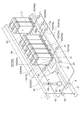
図1~図4は、幾つかの実施形態に係る燃料電池モジュール10(10A、10B)及びその構成部品を示す。図1~図4において、モジュール10(10A、10B)の内部には、燃料側電極、電解質及び酸素側電極等を夫々含む複数の燃料電池セルが収容されている。モジュール10の発電容量が大きい場合、燃料電池セルの数は膨大となるので、膨大な数の燃料電池セルは1個以上のカートリッジ11に収容される。あるいは、複数の燃料電池セルを有するセルスタックを形成させ、複数のセルスタックを1個以上のカートリッジ11に夫々収容する。また、燃料ガス供給管30から燃料電池セルを構成する燃料側電極に燃料ガスfが供給され、酸化性ガス供給系統20から酸素側電極に酸化性ガスaが供給される。これによって、複数の燃料電池セルで発電が起る。
本実施形態では、酸化性ガス供給系統20は、酸化性ガスaの流れ方向上流側に設けられた酸化性ガス供給主管21(第1ライン)及び酸化性ガス供給主管21の下流端に位置する分岐点22から分岐して複数のカートリッジ11毎に夫々接続される複数の酸化性ガス供給分岐管23(23a、23b)及び酸化性ガス供給分岐枝管24(24a、24b)(第2ライン)を含む。そして、酸化性ガス供給分岐管23又は酸化性ガス供給分岐枝管24に少なくとも1本の昇温用燃料ガス供給管42(42a、42b)又は43(43a、43b)が接続される。
上記構成において、モジュール10の起動時などの運転中において、昇温用燃料ガス供給管42又は43から酸化性ガス供給分岐管23又は酸化性ガス供給分岐枝管24に燃料ガスfを添加する。添加された燃料ガスfは燃料電池セルの酸素側電極で燃焼して燃料電池セルを昇温するため、起動時間を短縮することができる。燃料ガスfを燃焼させる手段として、例えば、酸素側電極に酸化触媒を担持させ、酸化性ガスが触媒燃焼可能な温度(例えば400℃以上)になったとき、酸素側電極の触媒作用によって燃料ガスfを燃焼させるようにする。複数の酸化性ガス供給分岐管23又は酸化性ガス供給分岐枝管24は夫々1個以上のカートリッジ11に接続されるため、昇温用燃料ガスfは複数のカートリッジ11にバランス良く供給される。これによって、モジュール10内に設けられた複数のカートリッジ11の温度分布のばらつきを抑制できるため、複数の燃料電池セルの発電性能のばらつきを抑制して発電性能を向上できる。
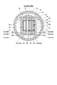
図5は、モジュール10の横断面図であり、カートリッジ11の内部に複数のセルスタック12が収容され、発電室55を形成する。複数のセルスタック12によって形成された発電室55を囲うように断熱材56、57、58及び59が設けられ、これら断熱材によって発電室55をその外側に対して断熱し、発電室55で発生する熱を外側へ逃がさないようにしている。
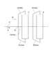
図6は、カートリッジ11の内部に収容されたセルスタック12の縦断面図であり、セルスタック12は複数の燃料電池セル14を含む。燃料電池セル14は、燃料側電極15、電解質16及び酸素側電極17を含んで構成される。セルスタック12は基体上に複数の燃料電池セル14が形成され、これら複数の燃料電池セル14によって発電が行われる。以下において、円筒形のセルスタック12を例として説明するが、円筒形以外に、例えば扁平円筒型や平板形のセルスタックとしてもよい。
図6は、カートリッジ11の内部に収容されたセルスタック12の縦断面図であり、セルスタック12は複数の燃料電池セル14を含む。燃料電池セル14は、燃料側電極15、電解質16及び酸素側電極17を含んで構成される。セルスタック12は基体上に複数の燃料電池セル14が形成され、これら複数の燃料電池セル14によって発電が行われる。以下において、円筒形のセルスタック12を例として説明するが、円筒形以外に、例えば扁平円筒型や平板形のセルスタックとしてもよい。
図6に示すように、セルスタック12は、円筒形状の基体管13と、基体管13の外周面に形成された複数の燃料電池セル14と、隣り合う燃料電池セル14の間に形成されたインタコネクタ18と、を含んで構成される。燃料電池セル14は、燃料側電極15と電解質16と酸素側電極17とが積層して形成されている。また、複数の燃料電池セル14のうち基体管13の軸方向一端に形成された燃料電池セル14の酸素側電極17に、インタコネクタ18を介して電気的に接続されたリード膜19と、基体管13の軸方向他端に形成された燃料電池セル14の燃料側電極15に電気的に接続されたリード膜(不図示)と、を備える。
インタコネクタ18は導電性を有し、隣り合う燃料側電極15の間で一方の燃料電池セル14の酸素側電極17と他方の燃料電池セル14の燃料側電極15とを電気的に接続し、隣り合う燃料電池セル同士を直列に接続する。リード膜19は導電性を有し、インタコネクタ18によって直列に接続された複数の燃料電池セル14で発電された直流電力をセルスタック12の端部付近まで導出する。
一実施形態では、図5に示すように、燃料ガス供給管30は、複数のカートリッジ11の上方に導設され、複数の燃料ガス供給枝管31を介して各カートリッジ11に接続される。燃料ガスfは、各カートリッジ11において燃料ガス供給管30から断熱材57の内側に設けられた燃料ガス供給室32に供給される。燃料ガス供給室32に供給された燃料ガスfは、セルスタック12を構成する基体管13の内部を通り、燃料電池セル14の発電に供される。発電に供された後の排燃料ガスf’は発電室55の下方に形成された排燃料ガス排出室33に流入し、排燃料ガス排出室33から排燃料ガス排出枝管34及び排燃料ガス排出管35を介してモジュール10外へ排出される。
一実施形態では、カートリッジ11の内部で発電室55の下方に酸化性ガス供給室25が設けられ、酸化性ガスaは酸化性ガス供給分岐管23(23a、23b)及び酸化性ガス供給分岐枝管24(24a、24b)を介して酸化性ガス供給室25に供給される。酸化性ガス供給室25に供給された酸化性ガスaは、セルスタック12と断熱材56との間に形成された隙間(不図示)から発電室55に流入し、燃料電池セル14の発電に供される。発電に用いられた後の排酸化性ガスa’は該隙間から発電室55の上方に形成された排酸化性ガス排出室26に流入し、さらに排酸化性ガス排出室26から排酸化性ガス排出枝管27を経て排酸化性ガス排出管28に排出される。
なお、図2及び図4には、排酸化性ガスa’の排出系統の図示は省略されている。
なお、図2及び図4には、排酸化性ガスa’の排出系統の図示は省略されている。
一実施形態では、図1~図4に示すように、燃料ガス供給管30と酸化性ガス供給主管21との間に接続管40が接続される。接続管40にはバルブ50が設けられ、燃料ガス供給管30を流れる燃料ガスfの一部は、所望の時に昇温用燃料ガスfとして酸化性ガス供給主管21、酸化性ガス供給分岐管23及び酸化性ガス供給分岐枝管24を介してカートリッジ11に供給される。しかし、この供給系統を用いて昇温用燃料ガスをカートリッジ11に供給する場合、カートリッジ11毎に供給する燃料ガスfの流量や濃度を調整できない。従って、カートリッジ11毎の温度調整はできない。
そこで、図1及び図2に示す実施形態では、接続管40と昇温用燃料ガス供給管42(42a、42b)又は43(43a、43b)とを接続する昇温用燃料ガス供給主管41を設け、昇温用燃料ガスfを接続管40から昇温用燃料ガス供給主管41を介して昇温用燃料ガス供給管42又は43に供給するようにする。これによって、昇温用燃料ガスを複数のカートリッジ11にバランス良く供給でき、複数のカートリッジ11の温度分布のばらつきを抑制できる。
そこで、図1及び図2に示す実施形態では、接続管40と昇温用燃料ガス供給管42(42a、42b)又は43(43a、43b)とを接続する昇温用燃料ガス供給主管41を設け、昇温用燃料ガスfを接続管40から昇温用燃料ガス供給主管41を介して昇温用燃料ガス供給管42又は43に供給するようにする。これによって、昇温用燃料ガスを複数のカートリッジ11にバランス良く供給でき、複数のカートリッジ11の温度分布のばらつきを抑制できる。
一実施形態では、図1~図4に示すように、1個以上のカートリッジ11を備え、各カートリッジ11には複数の燃料電池セル14が収容されている。例えば、図5及び図6に示すように、複数の燃料電池セル14はセルスタック12として収容される。酸化性ガス供給分岐管23は酸化性ガス供給分岐枝管24を介して夫々1個以上のカートリッジ11に接続される。従って、1個のカートリッジ11に収容された複数の燃料電池セル14に対して、酸化性ガス供給分岐管23及び酸化性ガス供給分岐枝管24を構成する1本又は少数の配管から酸化性ガスaを供給可能に構成することで、酸化性ガス供給分岐管23及び酸化性ガス供給分岐枝管24の本数を低減でき、これら配管を簡素化できる。
一実施形態では、図1及び図2に示すように、昇温用燃料ガス供給管42又は43にバルブ51が設けられる。バルブ51によって昇温用燃料ガス供給管42及び43から酸化性ガス供給分岐管23及び酸化性ガス供給分岐枝管24に供給される燃料ガスfの流量を調整できるので、モジュール10の複数の燃料電池セル14の温度分布のばらつきをさらに抑制できる。
なお、バルブ51は開閉動作のみが可能な開閉弁であってもよく、あるいは流量が調整可能な流量調整弁で構成されていてもよい。
なお、バルブ51は開閉動作のみが可能な開閉弁であってもよく、あるいは流量が調整可能な流量調整弁で構成されていてもよい。
一実施形態では、図2及び図4に示すように、燃料電池セル14の温度を検出するための温度センサ53を備える。この実施形態によれば、温度センサ53の検出値に基づいてオペレータがバルブ51の開閉を操作することで、モジュール10内の複数の燃料電池セル14の温度分布のばらつきをさらに抑制できる。
この実施形態において、カートリッジ11毎に複数の温度センサ53を設けてもよい。また、温度センサ53の検出値に基づいてバルブ51の開度を自動調整するように構成してもよい。
この実施形態において、カートリッジ11毎に複数の温度センサ53を設けてもよい。また、温度センサ53の検出値に基づいてバルブ51の開度を自動調整するように構成してもよい。
一実施形態では、図1~図4に示すように、圧力容器54を設け、圧力容器54の内部に複数の燃料電池セル14を収容するようにする。他方、バルブ51は圧力容器54の外部に配置される。この実施形態によれば、バルブ51を圧力容器54の外部に設けることで、オペレータが直接バルブ51を操作できる。また、圧力容器54の内部に燃料電池セル14を収容することで、燃料電池セル14に加圧した燃料ガスf及び酸化性ガスaを供給しても安全であり、加圧した燃料ガスf及び酸化性ガスaを供給することで、モジュール10の発電性能を向上できる。
図5に示す実施形態では、圧力容器54の内面に断熱材60が設けられる。これによって、圧力容器54内の熱が圧力容器54外に逃げるのを抑制できる。
図5に示す実施形態では、圧力容器54の内面に断熱材60が設けられる。これによって、圧力容器54内の熱が圧力容器54外に逃げるのを抑制できる。
一実施形態では、図1~図5に示すように、昇温用燃料ガス供給管42及び43は圧力容器54を貫通して設けられ、圧力容器54の外部に位置する外部配管部44aと、圧力容器54の内部に位置する内部配管部44bと、で構成される。この実施形態によれば、昇温用燃料ガス供給管42及び43の一部を圧力容器54の外部に配置することで、圧力容器54を小型化できる。
一実施形態では、図3及び図4に示すように、排燃料ガス排出管35から分岐して燃料ガス供給管30に接続される再循環管45が設けられる。燃料電池セル14の発電に供された後排燃料ガス排出管35に排出された排燃料ガスf’の少なくとも一部が再循環管45に設けられた再循環ブロワ52によって、再度燃料電池セル14に供給されるように構成される。
一実施形態では、図3及び図4に示すように、昇温用燃料ガス供給主管41(41a、41b)の上流端は再循環管45に接続される。排燃料ガスf’の少なくとも一部は、昇温用燃料ガス供給管42(42a、42b)又は43(43a、43b)を介して酸化性ガス供給分岐管23(23a、23b)及び酸化性ガス供給分岐枝管24(24a、24b)に添加され、燃料電池セル14の空気側に供給されるように構成される。これによって、燃料電池セル14から一旦排出された排燃料ガスf’を昇温用燃料ガスfとして再利用できると共に、希釈された排燃料ガスf’を昇温用燃料ガス供給管42又は43に供給することで、各場所に配置された複数の昇温用燃料ガス供給管内の燃料ガスfの濃度を調整できる。
一実施形態では、複数のカートリッジ11は列状に配置される。図1~図4に示す実施形態では一列に配置されている。そして、酸化性ガス供給分岐管23及び酸化性ガス供給分岐枝管24は、複数のカートリッジ11の配列方向に沿って配置された少なくとも1本の分岐管23(23a、23b)と、分岐管23から分岐して各カートリッジ11に接続される分岐枝管24(24a、24b)と、を含んで構成される。また、1本又は複数本の昇温用燃料ガス供給管42は、カートリッジ配列方向中央部に設けられた分岐管23に接続される。
この実施形態によれば、カートリッジ配列方向中央部に設けられた分岐管23(23a、23b)に昇温用燃料ガスfが供給されるため、下流側の複数のカートリッジ11に昇温用燃料ガスfをバランス良く供給できる。
この実施形態によれば、カートリッジ配列方向中央部に設けられた分岐管23(23a、23b)に昇温用燃料ガスfが供給されるため、下流側の複数のカートリッジ11に昇温用燃料ガスfをバランス良く供給できる。
一実施形態では、図1及び図2に示すように、複数のカートリッジ11は列状に配置される。酸化性ガス供給分岐管23は、複数のカートリッジ11の配列方向に沿って配置された少なくとも1本の分岐管23と、分岐管23から分岐して各カートリッジ11に接続される分岐枝管24と、を含んで構成される。また、1本又は複数本の個別カートリッジ昇温用燃料ガス供給管43(43a、43b)は、カートリッジ配列方向両端の少なくとも一方側に設けられた1本又は複数本の分岐枝管24に接続される。
列状に配置された複数のカートリッジ11に1本又は少数本の管路から酸化性ガスaを供給する場合、配列方向端側のカートリッジ11の温度は低くなりがちである。これに対し、この実施形態によれば、配列方向端側の個別カートリッジ11に直接昇温用燃料ガスfを不足なく供給できる。
列状に配置された複数のカートリッジ11に1本又は少数本の管路から酸化性ガスaを供給する場合、配列方向端側のカートリッジ11の温度は低くなりがちである。これに対し、この実施形態によれば、配列方向端側の個別カートリッジ11に直接昇温用燃料ガスfを不足なく供給できる。
一実施形態では、図2及び図4に示すように、複数の酸化性ガス供給分岐管23(23a、23b)が分岐点22で酸化性ガス供給主管21から分岐し、各酸化性ガス供給分岐管23(23a、23b)はカートリッジ列の側方に配置された直線配管部を含む。この直線配管部はカートリッジ列を挟みカートリッジ列の両側にカートリッジ列に沿って位置する。この実施形態によれば、列状に配置された複数のカートリッジ11の両側に上記直線配管部が配置されるため、酸化性ガス供給分岐管23及び酸化性ガス供給分岐枝管24をコンパクト化できる。また、1個のカートリッジ11に収容された複数の燃料電池セル14に対して共通の酸化性ガス流路が形成される場合、各カートリッジ11の両側から昇温用燃料ガスfを供給できるため、各カートリッジ11に収容された複数の燃料電池セル14に供給される昇温用燃料ガスfの流量をカートリッジの配列方向に対し左右方向の調整ができる。
図7~図9は酸化性ガス供給系統20の他の幾つかの実施形態を示す。図7に示す燃料電池モジュールは、複数の燃料電池セル14を収容する1個のカートリッジ11を備える。酸化性ガス供給系統20は、酸化性ガスaの流れ方向上流側に設けられた1本の酸化性ガス供給主管21と、酸化性ガス供給主管21の下流端に位置する分岐点22で酸化性ガス供給主管21から分岐した2本の酸化性ガス供給分岐管23(23a、23b)で構成される。2本の酸化性ガス供給分岐管23はカートリッジ11の両端側に接続され、カートリッジ11の両端側からカートリッジ11に収容された複数の燃料電池セル14に酸化性ガスaが供給される。
図8に示す燃料電池モジュールは、一列に配置された複数のカートリッジ11を備える。酸化性ガス供給系統20は、酸化性ガスaの流れ方向上流側に設けられた1本の酸化性ガス供給主管21と、分岐点22で分岐する酸化性ガス供給分岐管23(23a)と、分岐点22より下流側で酸化性ガス供給分岐管23(23a)から分岐する酸化性ガス供給分岐枝管24(24a)と、で構成される。酸化性ガス供給分岐枝管24(24a)は各カートリッジ11の一端側に接続され、各カートリッジ11に酸化性ガスaを供給する枝管で構成される。
図9に示す燃料電池モジュールは、一列に配置された複数のカートリッジ11を備える。酸化性ガス供給系統20は、酸化性ガスaの流れ方向上流側に設けられた1本の酸化性ガス供給主管21と、分岐点22及び分岐点22の下流側で分岐する酸化性ガス供給分岐管23(23a)及び酸化性ガス供給分岐枝管24(24a、24b)と、で構成される。酸化性ガス供給分岐枝管24(24a、24b)は各カートリッジ11において酸化性ガス供給分岐管23(23a)から分岐する枝管で構成される。酸化性ガス供給分岐枝管24(24a、24b)は各カートリッジ11の両端側に接続され、各カートリッジ11に酸化性ガスaを供給する。
一実施形態に係る燃料電池モジュール10の運転方法は、モジュール10の起動時に行う。図10に示すように、少なくとも1本の昇温用燃料ガス供給管42又は43から酸化性ガス供給分岐管23及び酸化性ガス供給分岐枝管24を流れる酸化性ガスaに燃料ガスfを添加する(ステップS10)。この燃料ガスfが酸素側電極17で燃焼して燃料電池セル14を昇温させる(昇温ステップS12)。燃料ガスfの燃焼手段として、例えば、酸素側電極17に担持された酸化触媒によって、酸素側電極17が触媒燃焼可能な温度(例えば400℃以上)のとき、燃料ガスfが可燃限界濃度以下でも燃料ガスfを燃焼できる。ステップS10では、燃料電池モジュール10内に設けられた複数の領域のカートリッジ11に酸化性ガスaに昇温用燃料ガスfを添加できるので、モジュール10の設けられた複数の燃料電池セル14を所望の温度分布に調整できる。これによって、モジュール10の燃料電池セル14の温度分布のばらつきを抑制できる(ステップS14)。また、添加された燃料ガスfは燃料電池セル14の酸素側電極17で燃焼して燃料電池セル14を昇温するため、起動時間を短縮できる。
一実施形態では、ステップS10において、複数の燃料電池セル14から排出される燃料ガスfの少なくとも一部を酸化性ガス供給分岐管23を流れる酸化性ガスaに添加する(再利用ステップS10a)。この実施形態によれば、燃料電池セル14から排出される排燃料ガスf’を昇温用燃料ガスfとして再利用できると共に、希釈された排燃料ガスf’を複数の昇温用燃料ガス供給管42又は43内に供給することで、各場所に配置された複数の昇温用燃料ガス供給管42又は43内の燃料ガスfの濃度の調整が容易になる。
一実施形態に係る燃料電池モジュール10の運転方法は、定格発電時又は部分負荷時に行う。図11に示すように、少なくとも1本の昇温用燃料ガス供給管42又は43から酸化性ガス供給分岐管23及び酸化性ガス供給分岐枝管24を流れる酸化性ガスaに燃料ガスfを添加する(ステップS20)。この燃料ガスfが酸素側電極17で燃焼して燃料電池セル14を昇温させる(温度均一ステップS22)。これによって、モジュール10の発電時又は部分負荷時において、モジュール10内の複数のカートリッジ11における温度分布のばらつきを抑制できる(ステップS24)。例えば、定格発電時には複数のカートリッジ11の温度の不均一を緩和することができ、発電性能を高めることができる。部分負荷時には、燃料電池セル14の温度が設定温度より下がり過ぎる傾向にあるが、ステップS20及び温度均一ステップS22によって、発電による温度維持が困難なカートリッジを加熱することで部分負荷の運用範囲を拡大することができる。
一実施形態では、ステップS20において、複数の燃料電池セル14から排出される燃料ガスfの少なくとも一部を酸化性ガス供給分岐管23を流れる酸化性ガスaに添加する(再利用ステップS20a)。
なお、上記幾つかの実施形態に係る運転方法は、モジュール10の起動時又は定格発電時、部分負荷時以外の運転時、例えば負荷変動時にも適用できる。
なお、上記幾つかの実施形態に係る運転方法は、モジュール10の起動時又は定格発電時、部分負荷時以外の運転時、例えば負荷変動時にも適用できる。
一実施形態では、燃料電池セル14が高温となる、例えば、SOFC、及び溶融炭酸形燃料電池(MCFC)(Molten Carbonate Fuel Cell)等に好適である。これらの燃料電池は運転可能な高温まで燃料電池セルを加熱する必要があり、発電開始までの時間が長いという問題があったが、上記実施形態を適用することで、発電開始までの時間を短縮できる。
燃料電池モジュール10は、GTCC(Gas Turbine Combined Cycle:ガスタービンコンバインドサイクル発電)、MGT(Micro Gas Turbine:マイクロガスタービン)、又はターボチャージャと組み合わされて利用される複合発電システムに適用されることがある。
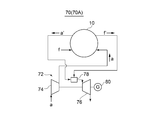
図12は、一実施形態に係る発電システム70(70A)を示す系統図である。図12において、発電システム70(70A)は、上記構成の幾つかの実施形態に係る燃料電池モジュール10と、ガスタービン72(回転機器)とを備える。ガスタービン72を構成する圧縮機74に酸化性ガスaが供給され、酸化性ガスaは圧縮機74で圧縮された後、酸化性ガス供給系統20を介して燃料電池モジュール10に供給される。燃料電池モジュール10で発電のための化学反応に用いられた後の排酸化性ガスa’及び排燃料ガスf’は、排酸化性ガス排出管28及び排燃料ガス排出管35を介してガスタービン72を構成する燃焼器78に送られ、燃焼器78で高温の燃焼ガスを生成する。この燃焼ガスをタービン76で断熱膨張させることにより発生する回転動力により、発電機80で電力が生成されると共に、圧縮機74を駆動することで、圧縮ガスが発生する。この圧縮ガスを酸化性ガスaとして燃料電池モジュール10の酸化性ガス供給系統20に供給する。燃料電池モジュール10は、圧縮された酸化性ガスaと燃料ガスfを用いて発電する。
上記構成によれば、上記幾つかの実施形態に係る燃料電池モジュール10を備えることで、モジュール10内に設けられた複数の燃料電池セル14の温度分布のばらつきを抑制でき、これによって、複数の燃料電池セル14の発電性能のばらつきを抑制して発電性能を向上できる。また、燃料電池モジュール10に圧縮された酸化性ガスaを供給できるので、発電効率を向上できる。また、燃料電池モジュール10から排気される排酸化性ガスa’と排燃料ガスf’で燃焼器78を駆動させて回転動力を発生させるため、発電システム70(70A)の所要動力を低減できる。さらに、燃料電池モジュール10とガスタービン72の両方で複合的に発電できるので、発電量を増加できる。
図13は、一実施形態に係る発電システム70(70B)を示す系統図である。発電システム70(70B)は、回転機器としてターボチャージャ82が用いられる。図13において、ターボチャージャ82を構成する圧縮機84に酸化性ガスaを供給して圧縮し、圧縮された酸化性ガスaを燃料電池モジュール10に供給する。燃料電池モジュール10で発電のための化学反応に用いられた後の排酸化性ガスa’及び排燃料ガスf’は、排酸化性ガス排出管28及び排燃料ガス排出管35を介してターボチャージャ82を構成するタービン86に送られ、タービン86を回転させて回転動力が発生する。この回転動力で圧縮機84を駆動することで、圧縮ガスが発生する。
この実施形態によれば、モジュール10内に設けられた複数の燃料電池セル14の温度分布のばらつきを抑制でき、これによって、複数の燃料電池セル14の発電性能のばらつきを抑制して発電性能を向上できる。従って、発電システム70(70B)の発電効率を向上でき、かつ所要動力を低減できる。
この実施形態によれば、モジュール10内に設けられた複数の燃料電池セル14の温度分布のばらつきを抑制でき、これによって、複数の燃料電池セル14の発電性能のばらつきを抑制して発電性能を向上できる。従って、発電システム70(70B)の発電効率を向上でき、かつ所要動力を低減できる。
幾つかの実施形態によれば、燃料電池モジュールに収容された複数のカートリッジ及び発電セルの温度分布を所望の温度分布に調整でき、これによって、モジュールの発電性能を向上できる。
10 燃料電池モジュール
11 カートリッジ
12 セルスタック
13 基体管
14 燃料電池セル
15 燃料側電極
16 電解質
17 酸素側電極
18 インタコネクタ
19 リード膜
20 酸化性ガス供給系統
21 酸化性ガス供給主管(第1ライン)
22 分岐点
23(23a、23b) 酸化性ガス供給分岐管(第2ライン)
24(24a、24b) 酸化性ガス供給分岐枝管(第2ライン)
25 酸化性ガス供給室
26 排酸化性ガス排出室
27 排酸化性ガス排出枝管
28 排酸化性ガス排出管
30 燃料ガス供給管
31 燃料ガス供給枝管
32 燃料ガス供給室
33 排燃料ガス排出室
34 排燃料ガス排出枝管
35 排燃料ガス排出管
40 接続管
41(41a、41b) 昇温用燃料ガス供給主管
42(42a、42b) 昇温用燃料ガス供給管
43(43a、43b) 個別カートリッジ昇温用燃料ガス供給管
44a 外部配管部
44b 内部配管部
45 再循環管
50、51 バルブ
52 再循環ブロワ
53 温度センサ
54 圧力容器
55 発電室
56、57、58、59、60 断熱材
70(70A、70B) 発電システム
72 ガスタービン
74、84 圧縮機
76、86 タービン
82 ターボチャージャ
78 燃焼器
80 発電機
a 酸化性ガス
a’ 排酸化性ガス
f 燃料ガス
f’ 排燃料ガス
11 カートリッジ
12 セルスタック
13 基体管
14 燃料電池セル
15 燃料側電極
16 電解質
17 酸素側電極
18 インタコネクタ
19 リード膜
20 酸化性ガス供給系統
21 酸化性ガス供給主管(第1ライン)
22 分岐点
23(23a、23b) 酸化性ガス供給分岐管(第2ライン)
24(24a、24b) 酸化性ガス供給分岐枝管(第2ライン)
25 酸化性ガス供給室
26 排酸化性ガス排出室
27 排酸化性ガス排出枝管
28 排酸化性ガス排出管
30 燃料ガス供給管
31 燃料ガス供給枝管
32 燃料ガス供給室
33 排燃料ガス排出室
34 排燃料ガス排出枝管
35 排燃料ガス排出管
40 接続管
41(41a、41b) 昇温用燃料ガス供給主管
42(42a、42b) 昇温用燃料ガス供給管
43(43a、43b) 個別カートリッジ昇温用燃料ガス供給管
44a 外部配管部
44b 内部配管部
45 再循環管
50、51 バルブ
52 再循環ブロワ
53 温度センサ
54 圧力容器
55 発電室
56、57、58、59、60 断熱材
70(70A、70B) 発電システム
72 ガスタービン
74、84 圧縮機
76、86 タービン
82 ターボチャージャ
78 燃焼器
80 発電機
a 酸化性ガス
a’ 排酸化性ガス
f 燃料ガス
f’ 排燃料ガス
Claims (15)
- 燃料側電極、電解質及び酸素側電極を夫々含む複数の燃料電池セルと、
前記燃料側電極に燃料ガスを供給する燃料ガス供給管と、
第1ライン、及び、前記第1ラインの下流端に位置する分岐点から分岐して1以上の前記燃料電池セルに夫々接続される複数の第2ラインを含み、前記複数の燃料電池セルの前記酸素側電極に酸化性ガスを供給する酸化性ガス供給管と、
前記分岐点より下流側の前記第2ラインに接続された少なくとも1本の昇温用燃料ガス供給管と、
を備えることを特徴とする燃料電池モジュール。 - 前記燃料電池セルから排燃料ガスを排出する排燃料ガス排出管を備え、
前記昇温用燃料ガス供給管の上流端は前記排燃料ガス排出管に接続され、前記排燃料ガス排出管に排出された前記排燃料ガスの少なくとも一部は前記昇温用燃料ガス供給管及び前記第2ラインを介して前記燃料電池セルに供給されるように構成されることを特徴とする請求項1に記載の燃料電池モジュール。 - 2以上の前記燃料電池セルが各々に収容された1以上のカートリッジを備え、
各々の前記第2ラインは、前記1以上のカートリッジに接続されることを特徴とする請求項1又は2に記載の燃料電池モジュール。 - 複数の前記カートリッジが列状に配置され、
前記第2ラインは、前記複数のカートリッジの配列方向に沿って配置された少なくとも1本の分岐管と、該分岐管から分岐して前記複数のカートリッジの各々に接続される枝管と、を含み、
前記少なくとも1本の昇温用燃料ガス供給管は、前記複数のカートリッジの配列方向中央部に設けられた前記1本の分岐管に接続された昇温用燃料ガス供給管を含むことを特徴とする請求項3に記載の燃料電池モジュール。 - 複数の前記カートリッジが列状に配置され、
前記第2ラインは、前記複数のカートリッジの配列方向に沿って配置された少なくとも1本の分岐管と、該分岐管から分岐して前記複数のカートリッジの各々に接続される枝管と、を含み、
前記少なくとも1本の昇温用燃料ガス供給管は、前記複数のカートリッジの配列方向両端の少なくとも一方側に設けられた前記カートリッジに接続される前記枝管に接続される昇温用燃料ガス供給管を含むことを特徴とする請求項3又は4に記載の燃料電池モジュール。 - 各々の前記第2ラインが、カートリッジ列の側方に位置する直線配管部を含み、前記複数の第2ラインの各々の前記直線配管部が前記カートリッジ列を挟んで前記カートリッジ列の両側に位置することを特徴とする請求項4又は5に記載の燃料電池モジュール。
- 前記昇温用燃料ガス供給管に設けられたバルブを備えることを特徴とする請求項1乃至6の何れか一項に記載の燃料電池モジュール。
- 前記燃料電池セルの温度を検出するための1個以上の温度センサを備えることを特徴とする請求項7に記載の燃料電池モジュール。
- 前記複数の燃料電池セルを収容する圧力容器を備え、
前記昇温用燃料ガス供給管は、前記圧力容器を貫通して設けられ、前記圧力容器の外部に位置する外部配管部と、前記圧力容器内部の内部に位置する内部配管部と、を含むことを特徴とする請求項1乃至8の何れか一項に記載の燃料電池モジュール。 - 前記昇温用燃料ガス供給管に設けられたバルブを備え、
前記バルブは前記圧力容器の外部に設けられることを特徴とする請求項9に記載の燃料電池モジュール。 - 請求項1乃至10の何れか一項に記載の燃料電池モジュールと、
前記燃料電池モジュールから排気される排燃料ガスと排酸化性ガスとを用いて回転動力を発生させる回転機器と、
を備え、
前記燃料電池モジュールには、前記回転動力を用いて圧縮された前記酸化性ガスが供給され、前記燃料電池モジュールは、前記燃料ガスと前記圧縮された酸化性ガスを用いて発電することを特徴とする発電システム。 - 前記回転機器は、ガスタービン又はターボチャージャで構成されることを特徴とする請求項11に記載の発電システム。
- 請求項1乃至10の何れか一項に記載の燃料電池モジュールの運転方法であって、
前記少なくとも1本の昇温用燃料ガス供給管から前記第2ラインを流れる前記酸化性ガスに前記燃料ガスを添加し、前記酸化性ガスを昇温させる昇温ステップを備えることを特徴とする燃料電池モジュールの運転方法。 - 前記昇温ステップにおいて、
前記燃料電池セルから排出される前記燃料ガスの少なくとも一部を前記第2ラインを流れる前記酸化性ガスに添加することを特徴とする請求項13に記載の燃料電池モジュールの運転方法。 - 前記昇温ステップを前記燃料電池モジュールの起動時、定格発電時又は部分負荷時に行うことを特徴とする請求項13又は14に記載の燃料電池モジュールの運転方法。
Priority Applications (4)
| Application Number | Priority Date | Filing Date | Title |
|---|---|---|---|
| CN201980091935.6A CN113424345A (zh) | 2019-02-25 | 2019-12-17 | 燃料电池模块、发电系统以及燃料电池模块的运转方法 |
| DE112019006687.0T DE112019006687T5 (de) | 2019-02-25 | 2019-12-17 | Brennstoffzellenmodul, Stromerzeugungssystem und Verfahren zum Betreiben von Brennstoffzellenmodul |
| US17/430,441 US20220123333A1 (en) | 2019-02-25 | 2019-12-17 | Fuel cell module, power generation system, and method of operating fuel cell module |
| KR1020217025770A KR20210114035A (ko) | 2019-02-25 | 2019-12-17 | 연료 전지 모듈, 발전 시스템 및 연료 전지 모듈의 운전 방법 |
Applications Claiming Priority (2)
| Application Number | Priority Date | Filing Date | Title |
|---|---|---|---|
| JP2019-032125 | 2019-02-25 | ||
| JP2019032125A JP6943904B2 (ja) | 2019-02-25 | 2019-02-25 | 燃料電池モジュール、発電システム及び燃料電池モジュールの運転方法 |
Publications (1)
| Publication Number | Publication Date |
|---|---|
| WO2020174825A1 true WO2020174825A1 (ja) | 2020-09-03 |
Family
ID=72239201
Family Applications (1)
| Application Number | Title | Priority Date | Filing Date |
|---|---|---|---|
| PCT/JP2019/049369 Ceased WO2020174825A1 (ja) | 2019-02-25 | 2019-12-17 | 燃料電池モジュール、発電システム及び燃料電池モジュールの運転方法 |
Country Status (6)
| Country | Link |
|---|---|
| US (1) | US20220123333A1 (ja) |
| JP (1) | JP6943904B2 (ja) |
| KR (1) | KR20210114035A (ja) |
| CN (1) | CN113424345A (ja) |
| DE (1) | DE112019006687T5 (ja) |
| WO (1) | WO2020174825A1 (ja) |
Families Citing this family (2)
| Publication number | Priority date | Publication date | Assignee | Title |
|---|---|---|---|---|
| JP6980045B2 (ja) | 2020-01-31 | 2021-12-15 | 三菱パワー株式会社 | 燃料電池発電システム |
| DE102022207969A1 (de) * | 2022-08-02 | 2024-02-08 | Robert Bosch Gesellschaft mit beschränkter Haftung | Brennstoffzellensystem und Verfahren zum Betreiben eines Brennstoffzellensystems |
Citations (5)
| Publication number | Priority date | Publication date | Assignee | Title |
|---|---|---|---|---|
| JPH0660896A (ja) * | 1992-08-04 | 1994-03-04 | Mitsubishi Electric Corp | 燃料電池式発電装置およびその運転方法 |
| JP2005183309A (ja) * | 2003-12-22 | 2005-07-07 | Mitsubishi Electric Corp | 燃料電池 |
| JP2009266588A (ja) * | 2008-04-24 | 2009-11-12 | Mitsubishi Heavy Ind Ltd | 燃料電池モジュール |
| JP2011086398A (ja) * | 2009-10-13 | 2011-04-28 | Panasonic Corp | 燃料電池システム及び燃料電池システムの運転方法 |
| JP2017147124A (ja) * | 2016-02-17 | 2017-08-24 | 三菱日立パワーシステムズ株式会社 | 燃料電池発電システムの制御装置、発電システム及び燃料電池発電システム制御方法 |
Family Cites Families (9)
| Publication number | Priority date | Publication date | Assignee | Title |
|---|---|---|---|---|
| JPS54119542A (en) | 1978-03-10 | 1979-09-17 | Honda Motor Co Ltd | Method and apparatus for coating |
| JP5244292B2 (ja) * | 2005-10-17 | 2013-07-24 | 三菱重工業株式会社 | 燃料電池モジュールおよび燃料電池システム |
| JP4949743B2 (ja) * | 2006-06-07 | 2012-06-13 | 株式会社日立製作所 | 固体酸化物形燃料電池システムおよびその起動方法 |
| US9874158B2 (en) | 2009-09-04 | 2018-01-23 | Lg Fuel Cell Systems, Inc | Engine systems and methods of operating an engine |
| EP2485310B1 (en) * | 2009-09-28 | 2017-07-19 | Kyocera Corporation | Fuel cell device |
| JP6125221B2 (ja) * | 2012-12-20 | 2017-05-10 | 三菱日立パワーシステムズ株式会社 | 発電システム及び発電システムの運転方法 |
| US20170288240A1 (en) * | 2016-03-31 | 2017-10-05 | Szu-Han Wu | Fuel cell power generation module |
| JP6700105B2 (ja) * | 2016-05-31 | 2020-05-27 | 日立造船株式会社 | 燃料電池システム |
| JP6817729B2 (ja) | 2016-06-27 | 2021-01-20 | 三菱パワー株式会社 | 燃料電池の制御装置及び制御方法並びに発電システム |
-
2019
- 2019-02-25 JP JP2019032125A patent/JP6943904B2/ja active Active
- 2019-12-17 CN CN201980091935.6A patent/CN113424345A/zh active Pending
- 2019-12-17 WO PCT/JP2019/049369 patent/WO2020174825A1/ja not_active Ceased
- 2019-12-17 US US17/430,441 patent/US20220123333A1/en not_active Abandoned
- 2019-12-17 KR KR1020217025770A patent/KR20210114035A/ko not_active Ceased
- 2019-12-17 DE DE112019006687.0T patent/DE112019006687T5/de not_active Withdrawn
Patent Citations (5)
| Publication number | Priority date | Publication date | Assignee | Title |
|---|---|---|---|---|
| JPH0660896A (ja) * | 1992-08-04 | 1994-03-04 | Mitsubishi Electric Corp | 燃料電池式発電装置およびその運転方法 |
| JP2005183309A (ja) * | 2003-12-22 | 2005-07-07 | Mitsubishi Electric Corp | 燃料電池 |
| JP2009266588A (ja) * | 2008-04-24 | 2009-11-12 | Mitsubishi Heavy Ind Ltd | 燃料電池モジュール |
| JP2011086398A (ja) * | 2009-10-13 | 2011-04-28 | Panasonic Corp | 燃料電池システム及び燃料電池システムの運転方法 |
| JP2017147124A (ja) * | 2016-02-17 | 2017-08-24 | 三菱日立パワーシステムズ株式会社 | 燃料電池発電システムの制御装置、発電システム及び燃料電池発電システム制御方法 |
Also Published As
| Publication number | Publication date |
|---|---|
| CN113424345A (zh) | 2021-09-21 |
| KR20210114035A (ko) | 2021-09-17 |
| US20220123333A1 (en) | 2022-04-21 |
| JP2020136229A (ja) | 2020-08-31 |
| JP6943904B2 (ja) | 2021-10-06 |
| DE112019006687T5 (de) | 2021-11-04 |
Similar Documents
| Publication | Publication Date | Title |
|---|---|---|
| WO2006090685A1 (ja) | 固体酸化物形燃料電池およびその運転方法 | |
| JP5779371B2 (ja) | 燃料電池およびその運転方法 | |
| JPH09259910A (ja) | 溶融炭酸塩型燃料電池とこれを用いた発電装置 | |
| US20090148733A1 (en) | Fuel cell system | |
| JP2008198423A (ja) | 燃料電池発電システム及びその運転方法 | |
| JP2015076399A (ja) | 燃料電池加熱装置および加熱方法とこれを含む燃料電池装置 | |
| JP2014163318A (ja) | 発電システム、発電システムの運転方法、及び制御装置 | |
| JP2006269419A (ja) | 固体酸化物形燃料電池および運転方法 | |
| JP6943904B2 (ja) | 燃料電池モジュール、発電システム及び燃料電池モジュールの運転方法 | |
| JP2004119299A (ja) | 燃料電池システム | |
| JP2007128717A (ja) | 燃料電池の運転方法 | |
| JP6749799B2 (ja) | 燃料電池の制御装置及び制御方法並びに発電システム | |
| KR20220120626A (ko) | 연료 전지 발전 시스템 | |
| US20140202167A1 (en) | Power generation system | |
| JP5248194B2 (ja) | 固体酸化物形燃料電池およびその起動方法 | |
| JP2018006003A (ja) | 燃料電池の制御装置及び制御方法並びに発電システム | |
| US20080160364A1 (en) | Solid oxide fuel cell module | |
| JP6029436B2 (ja) | 発電システム及び発電システムの運転方法 | |
| JP2006086019A (ja) | 固体酸化物形燃料電池および運転開始時の予熱方法 | |
| JP5000867B2 (ja) | 燃料電池発電システム | |
| KR102457726B1 (ko) | 연료전지의 오프가스 연소 시스템 | |
| KR20060095222A (ko) | 개질기용 연료 공급장치 및 연료 전지 시스템 | |
| JP6684021B2 (ja) | 燃料電池スタック | |
| JP7065415B2 (ja) | 燃料電池モジュールおよび燃料電池システム。 | |
| JP7033016B2 (ja) | 燃料電池モジュール |
Legal Events
| Date | Code | Title | Description |
|---|---|---|---|
| 121 | Ep: the epo has been informed by wipo that ep was designated in this application |
Ref document number: 19917409 Country of ref document: EP Kind code of ref document: A1 |
|
| ENP | Entry into the national phase |
Ref document number: 20217025770 Country of ref document: KR Kind code of ref document: A |
|
| 122 | Ep: pct application non-entry in european phase |
Ref document number: 19917409 Country of ref document: EP Kind code of ref document: A1 |