WO2020170996A1 - ワイヤレス給電システムおよび円形・球形・多面形状を有する受電器 - Google Patents
ワイヤレス給電システムおよび円形・球形・多面形状を有する受電器 Download PDFInfo
- Publication number
- WO2020170996A1 WO2020170996A1 PCT/JP2020/005953 JP2020005953W WO2020170996A1 WO 2020170996 A1 WO2020170996 A1 WO 2020170996A1 JP 2020005953 W JP2020005953 W JP 2020005953W WO 2020170996 A1 WO2020170996 A1 WO 2020170996A1
- Authority
- WO
- WIPO (PCT)
- Prior art keywords
- power
- coil
- receiver
- circuit
- resonance
- Prior art date
- Legal status (The legal status is an assumption and is not a legal conclusion. Google has not performed a legal analysis and makes no representation as to the accuracy of the status listed.)
- Ceased
Links
Images





Classifications
-
- H—ELECTRICITY
- H04—ELECTRIC COMMUNICATION TECHNIQUE
- H04B—TRANSMISSION
- H04B5/00—Near-field transmission systems, e.g. inductive or capacitive transmission systems
- H04B5/20—Near-field transmission systems, e.g. inductive or capacitive transmission systems characterised by the transmission technique; characterised by the transmission medium
- H04B5/24—Inductive coupling
- H04B5/26—Inductive coupling using coils
-
- H—ELECTRICITY
- H02—GENERATION; CONVERSION OR DISTRIBUTION OF ELECTRIC POWER
- H02J—ELECTRIC POWER NETWORKS; CIRCUIT ARRANGEMENTS OR SYSTEMS FOR SUPPLYING OR DISTRIBUTING ELECTRIC POWER; SYSTEMS FOR STORING ELECTRIC ENERGY
- H02J50/00—Circuit arrangements or systems for wireless supply or distribution of electric power
- H02J50/10—Circuit arrangements or systems for wireless supply or distribution of electric power using inductive coupling
- H02J50/12—Circuit arrangements or systems for wireless supply or distribution of electric power using inductive coupling of the resonant type
-
- H—ELECTRICITY
- H02—GENERATION; CONVERSION OR DISTRIBUTION OF ELECTRIC POWER
- H02J—ELECTRIC POWER NETWORKS; CIRCUIT ARRANGEMENTS OR SYSTEMS FOR SUPPLYING OR DISTRIBUTING ELECTRIC POWER; SYSTEMS FOR STORING ELECTRIC ENERGY
- H02J50/00—Circuit arrangements or systems for wireless supply or distribution of electric power
- H02J50/005—Mechanical details of housing or structure aiming to accommodate the power transfer means, e.g. mechanical integration of coils, antennas or transducers into emitting or receiving devices
-
- H—ELECTRICITY
- H02—GENERATION; CONVERSION OR DISTRIBUTION OF ELECTRIC POWER
- H02J—ELECTRIC POWER NETWORKS; CIRCUIT ARRANGEMENTS OR SYSTEMS FOR SUPPLYING OR DISTRIBUTING ELECTRIC POWER; SYSTEMS FOR STORING ELECTRIC ENERGY
- H02J50/00—Circuit arrangements or systems for wireless supply or distribution of electric power
- H02J50/40—Circuit arrangements or systems for wireless supply or distribution of electric power using two or more transmitting or receiving devices
-
- H—ELECTRICITY
- H02—GENERATION; CONVERSION OR DISTRIBUTION OF ELECTRIC POWER
- H02J—ELECTRIC POWER NETWORKS; CIRCUIT ARRANGEMENTS OR SYSTEMS FOR SUPPLYING OR DISTRIBUTING ELECTRIC POWER; SYSTEMS FOR STORING ELECTRIC ENERGY
- H02J7/00—Circuit arrangements for charging or discharging batteries or for supplying loads from batteries
-
- H—ELECTRICITY
- H02—GENERATION; CONVERSION OR DISTRIBUTION OF ELECTRIC POWER
- H02J—ELECTRIC POWER NETWORKS; CIRCUIT ARRANGEMENTS OR SYSTEMS FOR SUPPLYING OR DISTRIBUTING ELECTRIC POWER; SYSTEMS FOR STORING ELECTRIC ENERGY
- H02J7/00—Circuit arrangements for charging or discharging batteries or for supplying loads from batteries
- H02J7/855—Circuit arrangements for charging or discharging batteries or for supplying loads from batteries with circuits adapted for supplying loads from the battery
-
- H—ELECTRICITY
- H02—GENERATION; CONVERSION OR DISTRIBUTION OF ELECTRIC POWER
- H02J—ELECTRIC POWER NETWORKS; CIRCUIT ARRANGEMENTS OR SYSTEMS FOR SUPPLYING OR DISTRIBUTING ELECTRIC POWER; SYSTEMS FOR STORING ELECTRIC ENERGY
- H02J7/00—Circuit arrangements for charging or discharging batteries or for supplying loads from batteries
- H02J7/865—Battery or charger load switching, e.g. concurrent charging and load supply
-
- Y—GENERAL TAGGING OF NEW TECHNOLOGICAL DEVELOPMENTS; GENERAL TAGGING OF CROSS-SECTIONAL TECHNOLOGIES SPANNING OVER SEVERAL SECTIONS OF THE IPC; TECHNICAL SUBJECTS COVERED BY FORMER USPC CROSS-REFERENCE ART COLLECTIONS [XRACs] AND DIGESTS
- Y02—TECHNOLOGIES OR APPLICATIONS FOR MITIGATION OR ADAPTATION AGAINST CLIMATE CHANGE
- Y02E—REDUCTION OF GREENHOUSE GAS [GHG] EMISSIONS, RELATED TO ENERGY GENERATION, TRANSMISSION OR DISTRIBUTION
- Y02E60/00—Enabling technologies; Technologies with a potential or indirect contribution to GHG emissions mitigation
- Y02E60/10—Energy storage using batteries
Definitions
- the present invention relates to a wireless power feeding system, particularly a system using magnetic coupling of an LC resonance circuit.
- Patent Document 1 discloses a wireless power feeding method and a power feeding system capable of expanding the use of a wider range of frequencies in wireless power feeding capable of feeding power to a relatively long distance by coupling by electromagnetic field resonance.
- the electromagnetic field resonance wireless power feeding method is for wireless power feeding in which a power transmission circuit of a power transmission device and a power reception circuit of a power reception device are coupled by electromagnetic field resonance, and the power transmission device is configured to supply two different frequency components f1 and f2 to a power source 2.
- the resonance frequency of the power transmission circuit as f1 and/or f2
- the conditions of the power transmission circuit are periodically changed to an electric transient state in which the current and/or voltage is not stable, and the power receiving device is set to the resonance frequency of the power receiving circuit. It is characterized in that (f2-f1) or (f1+f2) due to the beat phenomenon is set, and electric power at the frequency of (f2-f1) or (f1+f2) is supplied to the load.
- Patent Document 2 discloses a very simple wireless power feeder using a loop coil as a power transmission device.
- the power transmission loop coil provided in the power transmission device extracts electric energy from the DC power supply and generates periodically changing electromagnetic field resonance energy in the space.
- the power receiving loop coil provided in the power receiver extracts the periodically changing electromagnetic field resonance energy from the space as electric energy and supplies electric power to the load.
- the power transmitting loop coil and the power receiving loop coil are electromagnetically resonantly coupled, and power is wirelessly supplied from the power transmitting device to the power receiver.
- Patent Document 3 discloses a wireless power supply system that includes a plurality of relay devices and that suppresses a reduction in power transmission efficiency due to the relay devices.
- a power transmission device that transmits the power to be fed, a plurality of relay devices that relay the power transmitted from the power transmission device, a power receiver that receives the power relayed by the relay device, and a relay device via the relay device.
- a control device that controls the relay device so that power is transmitted through the transmission path that maximizes the transmission efficiency of the power in a plurality of transmission paths that transmit the power from the power transmission device to the power receiver. It is a thing.
- Patent Document 4 discloses a technique for increasing the power transmission efficiency of a magnetic resonance type wireless power feeding system.
- the magnetic resonance type wireless power supply system is connected to an AC power supply, a voltage conversion coil connected to the AC power supply, a power transmission side LC circuit, a power reception side LC circuit, an impedance conversion coil, and an impedance conversion coil.
- a load and a transmission efficiency adjustment capacitor connected in parallel to the load are provided.
- the power transmission side LC circuit is arranged in the vicinity of the voltage conversion coil and has a power transmission side coil and a power transmission side capacitor that are excited by electromagnetic induction with the voltage conversion coil.
- the power reception side LC circuit has a power reception side coil and a power reception side capacitor that resonate with the power transmission side coil.
- the impedance conversion coil is arranged in the vicinity of the power receiving side LC circuit and is excited by electromagnetic induction with the power receiving side coil.
- the transmission efficiency adjusting capacitor has a capacitance that increases the transmission efficiency of electric power from the AC power source to the load
- Patent Document 5 discloses a wireless power supply system that is versatile and highly applicable to all power receiving devices.
- a wireless power feeding system is a wireless power feeding system that wirelessly feeds electric power from a power feeding stand having a power feeding section to a power receiving apparatus equipped with a power receiving section, and an intermediate member is provided between the power feeding stand and the power receiving apparatus. Characterize. Even when the power receiving device is different, power can be supplied by a single power feeder. Further, since the power receiving device can change the arrangement of the power receiving device during power feeding, it is possible to provide a wireless power feeding system having high versatility and high applicability.
- Patent Document 6 discloses a device that enables power to be supplied from a power feeder to a power receiver even when there is a mismatch in the method, size, or shape of the power feeder and the power receiver in the wireless power feeder.
- the range of power receivers that can be fed by the power feeder can be widened.
- a detachable converter is provided between the power feeder and the power receiver. The converter functions by using a magnetic circuit, an electric passive element, re-feeding, or the like so that the apparent method, size, and shape of the power receiver from the power feeder match.
- Patent Document 7 discloses a wireless power feeding technology that performs highly efficient power transmission even when the degree of coupling between the transmitting coil and the receiving coil changes.
- the wireless power feeder includes a resonant circuit and a multi-tone power source, and transmits a power signal including an electric field, a magnetic field, or an electromagnetic field.
- the resonance circuit includes a transmission coil and a resonance capacitor that are connected in series.
- the multi-tone power supply outputs a multi-tone signal obtained by superimposing sinusoidal signals having a plurality of frequencies to a resonance circuit.
- Patent Document 8 discloses a technique for improving power transmission efficiency in magnetic resonance type wireless power feeding.
- the wireless power feeder magnetically resonates the power feeding coil and the power receiving coil by resonating the capacitor and the power feeding coil.
- the resonance frequency at this time is f.
- the wireless power feeder supplies alternating current power having the resonance frequency f to the power feeding coil by alternately turning on and off the switching transistor and the switching transistor.
- Patent Document 9 discloses a technique for efficiently controlling power supply in magnetic field resonance type wireless power supply.
- the wireless power feeder is a device for wirelessly feeding power from the power feeding coil to the power receiving coil based on the magnetic field resonance phenomenon between the power feeding coil and the power receiving coil.
- the power transmission control circuit supplies AC power to the power feeding coil at a driving frequency. As a result, AC power is supplied from the power feeding coil to the power receiving coil.
- the phase detection circuit detects the phase difference between the voltage phase and the current phase of the AC power. Specifically, the phase difference is detected by comparing the first detection period in which the signal T2 is at a high level and the second detection period in which the signal S2 is at a high level, and detecting the length of the overlapping period.
- Patent Document 10 discloses a power feeder, a power receiver, and a wireless power feeding system capable of suppressing an increase in circuit scale and cost, reducing power loss, and capable of adjusting impedances on both the power feeding side and the power receiving side.
- the power feeder includes a power generation unit that generates power to be fed, a power feeding element formed by a coil to which the power generated by the power generation unit is fed, a resonance element that is coupled by electromagnetic induction, and an impedance on the power feeding side.
- An impedance detection unit that detects the impedance, a variable matching unit that includes an impedance matching function at the feeding point of the power feeding element according to the control signal, a storage unit that stores the impedance characteristic estimation information as a reference table, and at least the detected impedance And a control unit that obtains a state to be adjusted of the variable matching unit from the information and a reference table of the storage unit and outputs a control signal to the variable matching unit so as to be in the obtained state.
- Patent Document 11 discloses a technique for stabilizing a load voltage in magnetic field resonance type wireless power feeding. Electric power is transmitted from the power feeding coil to the power receiving coil by magnetic resonance.
- the VCO alternately turns on and off the switching transistor Q1 and the switching transistor Q2 at the drive frequency fo, supplies AC power to the power feeding coil, and supplies AC power from the power feeding coil to the power receiving coil.
- the phase detection circuit detects the phase difference between the current phase and the voltage phase, and the VCO adjusts the drive frequency fo so that the phase difference becomes zero.
- the load voltage changes, the detected value of the voltage phase is adjusted, and as a result, the drive frequency fo is adjusted.
- Patent Document 12 discloses a power receiving circuit capable of realizing a high Q value.
- the wireless power receiver receives a power signal S1 including any one of an electric field, a magnetic field, and an electromagnetic field transmitted from the wireless power feeder.
- the receiving coil L2 is for receiving the power signal S1.
- the electric potential of the first terminal of the power storage capacitor C3 is fixed.
- the first switch SW1 and the second switch SW2 are sequentially connected in series so as to form a closed loop with the receiving coil L2, and their connection point N1 is connected to the second terminal of the power storage capacitor C3.
- the third switch SW3 and the fourth switch SW4 are sequentially provided in series in a path parallel to the first switch SW1 and the second switch SW2, and the potential of the connection point N2 thereof is fixed.
- Patent Document 13 discloses a power feeder, a power receiver, and a wireless power feeding system capable of obtaining a wider frequency characteristic in the magnetic field resonance type.
- the power feeder includes a power generation unit that generates power to be fed, a power feeding element to which the power generated by the power generation unit is fed, and a plurality of resonant elements that are arranged in multiple stages and are coupled to each other in a magnetic field resonance relationship. Then, one resonance element of the plurality of resonance elements is coupled by electromagnetic induction by the feeding element.
- Fig. 11 shows a basic circuit diagram of a conventional wireless power feeding system.
- a series resonance circuit composed of a power supply coil and a resonance capacitor periodically controls ON/OFF of SW1, SW2, SW3, and SW4 provided on the power supply side, so that the phase detection circuit shifts the resonance frequency. Is detected as the phase of the frequency. To do so, try to periodically stop the electromagnetic induction from the power feeding coil, and immediately after stopping, at the predetermined timing (with SW1 and SW4 on and SW2 and SW3 off), the power receiving coil of the power receiver. Also, it can be determined by detecting that the electric energy stored in the capacitor is emitted as an electromagnetic wave at the same resonance frequency as a phase shift.
- the feeder may be provided with a dedicated receiving coil for detecting the resonance frequency in addition to the feeding coil.
- a dedicated receiving coil for detecting the resonance frequency in addition to the feeding coil.
- Some electronic devices use a built-in secondary battery. When such a secondary battery is discharged and consumed, it is generally removed from the electronic device for charging and attached to a dedicated charger for charging. Further, in order to support wireless power feeding of a product using a battery, a dedicated feeding coil and an electric circuit had to be provided, and the manufacturer had to redevelop a new version of the device.
- ⁇ Resonance circuit may be used for wireless power supply.
- the resonance circuit on the feeder side is selected to be a series resonance circuit or a parallel resonance circuit.
- the series resonance circuit easily sends a large amount of energy, but has a large loss.
- the parallel resonant circuit is the opposite, and is used to send a relatively small amount of energy, and has a characteristic that it is easy to create a stable resonant state.
- a series resonance circuit is adopted on the feeder side (see FIG. 11).
- the resonance state is detected and the frequency is adjusted, but on the power supply side, the resonance state of the resonance state is detected by using a receiving coil for detection or switching between feeding and receiving. It realizes detection and frequency adjustment.
- the power receiver side also detects the resonance state and sends the information to the power feeder side by some communication method (Qi standard, etc.). There are many factors that increase costs in such a system.
- An object of the present invention is to provide a power supply device that performs appropriate control in combination with a power receiver that is as simple as possible, and a wireless power supply system including a combination thereof.
- the present invention aims to provide a system that enables wireless charging using existing electronic equipment.
- the inventor of the present invention employs a parallel resonance circuit on the power feeder side.
- the power receiver has an extremely simple structure. I knew if I could provide an easy-to-use wireless power supply system based on this policy, so I was able to finally arrive at an appropriate system by repeating trial and error. Also, when wirelessly feeding power to a cylindrical receiver such as a dry battery, the ferrite coil shape and directivity to the magnetic flux from the feeder are high, so place it in one direction with respect to the feeder. Although it must be done, we proposed a method of receiving coil that can receive power from any direction by making the ferrite coil movable. At that time, by providing the movable part, it was possible to deal with the deterioration of the movable part. That is, a parallel resonance circuit is adopted on the power feeder side, and a ferrite coil capable of receiving power from any direction is used for the power receiver. The ferrite coil is a winding coil wound around one ferrite in two or three directions.
- the wireless power supply system A power supply coil that generates an electromagnetic wave; and a power supply device that has a power supply circuit unit that supplies power to the power supply coil to generate the electromagnetic wave, A receiver having a power receiving coil that receives electromagnetic waves emitted from the power feeding coil by electromagnetic induction, a power receiving circuit unit that recovers energy generated in the power receiving coil, and an internal secondary battery that stores the energy recovered by the power receiving circuit unit.
- the power receiver is A power receiver housing having the same outer shape as an existing battery and housing the power receiving coil, the power receiving circuit section, and the internal secondary battery, It further has two electrodes arranged at the same position as the existing battery,
- the power feeder is Further comprising a power supply table on which the power receiver can be placed,
- the power receiver is mounted on a battery holder built in another electronic device, and by mounting the electronic device together with the electronic device on the power supply stand in the mounted state, the power receiver wirelessly supplies power to the power receiver.
- the internal secondary battery is charged, and at the same time, electric power is supplied to the other electronic device by discharging.
- the power receiver can be treated like a battery and built into the electronic device, and charging can be performed while the power receiver is built-in.
- the power receiver discharges (powers Supply).
- the power feeding circuit unit of the power feeder is A resonance capacitor adjusted to a resonance frequency so as to form a parallel resonance circuit in combination with the feeding coil, A switch circuit that periodically repeats ON (driving state) and OFF (resonant state) of power supply to the power feeding coil; A frequency adjustment circuit for changing the frequency of the power supply to the power supply coil, A control circuit that controls both the switch circuit and the frequency adjustment circuit, and a resonance state sensor that detects a resonance state of the power feeding coil and outputs a detection signal to the frequency adjustment circuit and the control circuit.
- the control circuit is According to the information from the resonance state sensor, in order to have a stable resonance state with an optimum resonance frequency, the frequency and drive time of power supply are determined, and the switch circuit and the frequency adjustment circuit are controlled accordingly, When it is determined that the resonance state is abnormal, power supply is stopped. As a result, power supply according to the power receiver can be realized.
- the power receiver is Further having an external secondary battery connection terminal for connecting an external secondary battery, By connecting an external secondary battery to the connection terminal, a large capacity power receiver can be realized. As a result, it becomes possible to charge the secondary battery that is not placed on the power supply table.
- the power receiving coil built in the power receiver is a cylindrical or polygonal coil, It is characterized in that it is an air-core coil or a ferrite coil obtained by winding a coil around a columnar or polygonal ferrite.
- a power receiving coil having a shape to be incorporated in a power receiver housing or the like having the same shape as the dry battery, and to enhance the variety.
- the power receiver housing has the same shape as an existing dry battery, When the power receiver is placed on the power supply base, the power receiver further includes a power receiving coil support mechanism that is rotatable so as to face a predetermined direction. This allows the power receiving coil to face the power feeder, thereby improving the directivity of the power receiving coil.
- the power supply stand is It has a shape, pattern, or color that indicates the range in which power can be supplied, and also has one or more grooves,
- the groove can be placed without rolling when the power receiver housing has a columnar shape even when it is laid sideways, and it is also possible to mount an electronic device having a built-in power receiver. It is characterized by Accordingly, it is possible to easily mount the power receiver on the power supply table.
- the wireless power supply system A power supply coil that generates an electromagnetic wave; and a power supply device that has a power supply circuit unit that supplies power to the power supply coil to generate the electromagnetic wave, A receiver having a power receiving coil that receives electromagnetic waves emitted from the power feeding coil by electromagnetic induction, a power receiving circuit unit that recovers energy generated in the power receiving coil, and an internal secondary battery that stores the energy recovered by the power receiving circuit unit.
- the power receiver is A power receiver housing having the same outer shape as an existing battery and housing the power receiving coil, the power receiving circuit section, and the internal secondary battery, It further has two electrodes arranged at the same position as the existing battery,
- the power feeder is Further comprising a power supply table on which the power receiver can be placed,
- the power receiving coil of the power receiver is a ferrite coil in which one ferrite is wound in a plurality of winding directions, and each winding is a power receiving coil connected in series.
- the power receiver is a power receiving coil in which magnetic flux passes even in the direction and an electromotive force is generated by electromagnetic induction.
- the power receiver may be in the shape of a cylinder or in any rotation direction, and on that premise, the power receiver is treated like a battery, built into an electronic device, and charged with the built-in power receiver.
- the power receiver can discharge (supply power) to the electronic device during charging.
- the power feeding circuit unit of the power feeder is A resonance capacitor adjusted to a resonance frequency so as to form a parallel resonance circuit in combination with the feeding coil, A switch circuit that periodically repeats ON (driving state) and OFF (resonant state) of power supply to the power feeding coil; A frequency adjustment circuit for changing the frequency of the power supply to the power supply coil, A control circuit that controls both the switch circuit and the frequency adjustment circuit, and a resonance state sensor that detects a resonance state of the power feeding coil and outputs a detection signal to the frequency adjustment circuit and the control circuit.
- the control circuit is According to the information from the resonance state sensor, in order to have a stable resonance state with an optimum resonance frequency, the frequency and drive time of power supply are determined, and the switch circuit and the frequency adjustment circuit are controlled accordingly, When it is determined that the resonance state is abnormal, power supply is stopped. As a result, power supply according to the power receiver can be realized.
- the power receiver housing has the same shape as an existing dry battery, is mounted on a battery holder incorporated in another electronic device, and by mounting the electronic device together with the electronic device in the mounted state on the power supply table, The internal secondary battery is charged by wireless power feeding from the power feeder to the power receiver, and at the same time, electric power is supplied to the other electronic device by discharging.
- the power receiver having an internal secondary battery built in
- the winding of the ferrite coil of the power receiving coil of the power receiver is a ferrite coil wound in at least one ferrite in three directions or in three or more directions, and each winding is a power receiving coil connected in series.
- the internal secondary battery is charged by the wireless power supply, and at the same time, the other electronic device is discharged. It is characterized by supplying electric power.
- the power receiver since the power receiver has a simple structure, it is possible to discharge the electronic device (output as a battery) while charging the internal secondary battery in the power receiver. Therefore, by incorporating the power receiving coil, the circuit section, and the battery in the form of a commercially available battery, the device that used the battery can be replaced with the battery, and the power receiver of the present invention can be attached to the device, leaving the device attached. Since it can be charged wirelessly, there is no need to remove the battery for charging as in the conventional case, and it is possible to make a device capable of wireless power feeding without improving the device. It is possible to solve the environmentally problem of disposable batteries and propose more convenient secondary batteries.
- the power receiver since the power receiver is configured to use the ferrite coil capable of receiving power from any direction, even if the power receiver is oriented in any direction, the internal secondary inside the power receiver While charging the battery, it was possible to discharge to the electronic device (output as a battery). Therefore, by installing a power receiving coil, which is a ferrite coil that can receive power from any direction, a circuit section, and a battery into a cylindrical shape such as a commercially available dry battery, it is possible to replace the device that used the battery with the battery. Since the battery can be charged wirelessly with the power receiver of the invention attached to the device, it is not necessary to remove the battery for charging as in the conventional case, and the device can be wirelessly powered without improvement of the device. You can It is possible to solve the environmentally problem of disposable batteries and propose more convenient secondary batteries.
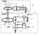
- FIG. 1 is a diagram showing a basic circuit configuration diagram of a wireless power feeding system according to the present invention.
- the wireless power feeding system according to the present invention is configured by a combination of a power feeder 10 and a power receiver 30. Electrical energy is supplied from the power feeder 10 to the power receiver 30.
- the power receiver 30 includes a power receiving coil 31, a capacitor 33, a rectifying circuit 34, and an internal secondary battery 37.
- the capacitor 33 may be connected to the power receiving coil 31 in series or in parallel. In the present invention, it is ideal to connect them in parallel.
- the internal secondary battery 37 is mounted inside the power receiver 30.
- the power receiving coil 31 provided in the power receiving device 30 allows the power feeding coil 11 of the power feeding device 10 to be greatly different in size, material, and electrical specifications.
- the power receiver 30 is housed in an existing dry battery or button battery type case, and substitutes for the battery by producing an electric output equivalent to that of the battery.
- the power supply device 10 adjusts the power supply coil 11, a resonance capacitor 13 that forms a resonance circuit together with the power supply coil 11, a switch circuit 14 for turning on and off power to the power supply coil 11, and a frequency supplied to the power supply coil 11. It includes a frequency adjusting circuit 15 (for example, a circuit including a PLL circuit), a resonance state sensor 16 for detecting a resonance state, and a power supply 18.
- a frequency adjusting circuit 15 for example, a circuit including a PLL circuit
- a resonance state sensor 16 for detecting a resonance state
- a power supply 18 for detecting a resonance state
- the characteristics of the power feeder 10 will be described.
- the power feeding coil 11 and the resonance capacitor 13 form a parallel resonance circuit.
- there is one switch the prior art depicted in FIG. 11 has two switches.
- the control circuit 17 controls the frequency adjusting circuit 15 and the switch circuit 14 to control the frequency and the power supply time.
- the resonance state sensor 16 for detecting the resonance state (mainly the frequency shift) is provided, and
- Figure 1 shows the basic circuit diagram (close to the block diagram).
- the basic circuit is provided with a power feeding coil 11 to generate electromagnetic waves and induce electromagnetic induction.
- At least the electric circuit of the power feeder 10 is provided with the resonance capacitor 13 and the power source 18, and creates a resonance relationship at a constant frequency with the power receiving coil 31 of the power receiver 30.
- the frequency at this time is called a resonance frequency, and generally, a frequency from 100 kHz to 500 kHz is used.
- the resonance frequency used in the present invention is not particularly limited.
- a slight deviation occurs in the resonance frequency due to the positional relationship and state of the power receiver 30.
- the situation changes depending on the position and inclination of the power receiving coil 31 of the power receiver 30. Therefore, if the power receiving coil 31 enters the range of the electromagnetic waves transmitted from the power feeding coil 11 (in the magnetic flux lines shown in FIG. 1), energy can be supplied.
- the inclusion of the power receiving coil 31 in the magnetic flux lines affects the power feeder side in the form of deviation of the resonance frequency. If the resonance frequency shifts, the efficiency of energy supply decreases.
- the shifted frequency or phase is detected by the resonance state sensor 16 (for example, a circuit including a phase detection circuit using a current sensor and a voltage sensor), and the frequency adjustment circuit 15 is used according to the frequency or phase, The frequency of the power feeding coil 11 is adjusted.
- the frequency adjustment circuit 15 is, for example, a circuit that adjusts the capacitance of the capacitor.
- control circuit 17 for controlling by a program using a microcontroller (an integrated circuit including a processor, a memory, a peripheral circuit) or a programmable logic device (an integrated circuit that can define and change an internal logic circuit). ..
- the control circuit 17 is connected to the resonance state sensor 16 (phase detection circuit).
- the resonance state sensor 16 detects a frequency shift or a phase shift and transmits the signal to the control circuit 17.
- the resonance state sensor 16 detects an abnormal frequency or phase, transmits the signal to the control circuit 17, and the control circuit 17 stops power supply. It becomes possible.
- the configuration of the basic circuit diagram described so far is the same as that of the conventional basic circuit depicted in FIG.
- a capacitor is connected in series to the power feeding coil, and the reference of the resonance frequency can be adjusted by the specifications of the capacitor.
- the conventional connection method of this circuit is generally called a series resonance circuit.
- the circuit of the power feeder 10 of the wireless power feeding system according to the present invention shown in FIG. 1 employs a parallel resonant circuit.
- resonance from the feeding coil is periodically stopped and detection is performed to detect a frequency shift.
- the circuit of FIG. 1 uses a method of detecting the resonance state without stopping the power supply to the power supply coil 11.
- the wireless power feeding system of the present invention is composed of the basic circuit shown in FIG.
- the difference from the conventional example of FIG. 11 is that the position of the resonance capacitor 13 of the power feeder 10 is connected in parallel with the power feeding coil 11.
- the circuit in which the resonance capacitor 13 is arranged is generally called a parallel resonance circuit.
- this parallel resonance circuit when SW1 is turned on to enter a stable resonance state and then SW1 is turned off, resonance with the power receiver 30 occurs while the energy stored in the power receiving coil 31 and the capacitor 33 is released.
- the feature is that the power feeder 10 continues the state.
- the on/off timing of the SW1 is controlled using a PLL (phase locked loop) circuit.
- the resonance state sensor 16 is a sensor that detects a resonance state, and detects transition of voltage/current, phase detection of resonance frequency, and the like.
- FIG. 2 is a schematic diagram of signal waveforms of the basic circuit of the power feeder 10 of FIG.
- FIG. 2A shows the waveform of the switch circuit 14 in FIG. 1, which is switched on when the waveform is high. That is, when the switch is turned on, the power supply 18 is supplied, so that the drive state, that is, the drive time is reached. The time when the switch is turned off and is not driven is the resonance state, that is, the resonance time.
- the power feeding device 10 may be in a resonance state with the power receiving device 30 regardless of whether it is in a driving state or a resonance state. If so, continue to supply energy.
- FIG. 2(B) shows the drive signal.
- the power supply 18 is turned on when the switch circuit 14 is turned on.
- FIG. 2C shows a sampling signal detected by the resonance state sensor 16 of FIG. 1, and the signal is turned on a plurality of times during the sampling time to perform detection (sampling).
- FIG. 2D is a received signal input to the resonance state sensor 16 of FIG. This signal indicates the state of the power feeding coil 11 in the resonance state. Although this signal waveform is simply shown, it is a signal having frequency characteristics, and the frequency component can be measured. Mainly, the voltage is converted into a digital value by an AD conversion circuit or the like, and the information is sent to the control circuit 17 in FIG.
- the control circuit 17 cooperates with the frequency adjusting circuit 15 to adjust the frequency at the time of power supply. At times, the frequency is intentionally shifted back and forth to examine the change in the state of FIG. 2(D). In the case where the power receiver 30 is in resonance with the power receiver 30, the control circuit 17 also adjusts the driving time in consideration of how the voltage in FIG.
- the resonance state sensor 16 in FIG. 2C also involves the loss of energy as the power feeder 10. Therefore, it is possible to suppress energy loss by performing sampling intermittently, for example, once a second, without performing each time.
- the specifications of the power supply 18, the power feeding coil 11 and the resonance frequency are determined according to the magnitude of energy to be sent and the width and height of the area to be fed with power.
- the resonance capacitor 13 is mainly determined according to the specifications of the reference resonance frequency.
- the circuit of the power receiver 30 includes a predetermined power receiving coil 31, and at least a capacitor 33 and a rectifying circuit 34.
- An internal secondary battery 37 is built in the power receiver 30.
- the internal secondary battery 37 is a rechargeable secondary battery.
- a super capacitor electric double layer capacitor
- the specifications and volume of the power receiving coil 31 and the resonance frequency at this time are set according to the magnitude of the energy to be received, but it is also possible to design so that the volume to be stored as the power receiver 30 has priority.
- the power receiver 30 side is often provided with a frequency detection circuit and a communication means for indicating to the power receiver 30 what state the power receiver 30 is in. ..
- the power is transmitted to the power feeder 10 by the communication means, and the power feeder 10 has a mechanism for appropriately adjusting the resonance frequency. In that case, the power receiver 10 needs a predetermined IC circuit.
- the circuit of the power receiver 30 is configured by a mechanism that simplifies to the utmost limit. With this simplified configuration, it is possible to discharge while charging, so you can charge the wireless power supply system with the charger inside the electronic device, and at the same time discharge the electronic device to generate power. Can be supplied.
- This mechanism applies the mechanism of the stylus pen that uses electromagnetic induction of Patent 5714194. That is, the stylus pen is composed of a simple power receiving coil and a capacitor. With this simple configuration, pen pressure information and switch on/off can be detected by a change in resonance frequency. If this principle is applied, it is possible to judge whether it is normal or abnormal and whether adjustment is necessary by looking at the state of the resonance frequency.
- FIG. 3 is a product image in one embodiment of the power receiver of the present invention.
- the power receiver of FIG. 1 may be composed of a housing having the same shape as a dry battery or a coin battery and an electrode terminal.
- FIG. 3 shows an embodiment of a power receiver having the same shape as the coin battery. This power receiver can be directly attached to the battery holder of the electronic device using the battery. The electric energy from the power feeder is received, and the built-in secondary battery built in the power receiver is charged. Therefore, it is possible to use the electronic device while supplying power without replacing or removing the battery.
- FIG. 4 is a configuration diagram of a power receiver having the same shape as a dry battery that is another embodiment of the power receiver of the present invention.
- the power receiver having the same shape as the dry battery is housed in a dry battery type case having electrode terminals of the dry battery.
- a power receiving coil 31, an internal secondary battery 37, and a power receiving circuit board (a condenser, a rectifying circuit, etc.) are housed inside a dry battery type case.
- a shield plate 36 that serves as an electromagnetic shield is attached to the power receiving coil 31.
- the power receiving circuit 35 substrate is placed in the gap between the power receiving coils 31.
- the electrode terminals 40A and 40B are attached from the power receiving circuit board 35 to the electrode terminals 39A and 39B provided in the power receiver housing 38 having the same shape as the dry battery.
- the electrode of the internal secondary battery 37 may be used as it is, instead of wiring connection.
- FIG. 5 is a diagram showing an internal configuration of a power receiver having the same shape as a coin battery (button battery).
- the power receiver of this embodiment has the same shape as a coin battery, and is housed in a power receiver housing 41 having the same shape as a coin battery having the same electrode terminal. It has an internal secondary battery 37, a shield plate 36, a power receiving coil 31, and a power receiving circuit board 35.
- a shield plate 36 serving as an electromagnetic shield is provided between the power receiving coil 31 and the internal secondary battery 37.
- the power receiving circuit board 35 and the internal secondary battery 37 are placed in the space between the power receiving coils.
- the electrode terminal 40 is attached from the power receiving circuit board 35 to the electrode terminal 39 of the power receiver housing 41 having the same shape as the coin battery.
- the electrode of the internal secondary battery 37 may be used as it is as one of the two electrode terminals.
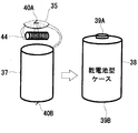
- FIG. 6 shows an example in which a power receiving coil with high directivity is used in a dry battery type power receiver (power receiver having a power receiver housing having the same shape as the dry battery).
- the power receiving coil 31 is a coil having high directivity (a cylindrical coil, an air core coil, a ferrite coil 44, etc.).
- a power receiving coil support mechanism is provided, and the coil is supported by the support mechanism. Shall be movable so that it faces the proper direction.
- the shape is not a circular ring shape, but a shape like a coil wound in a column shape.
- This coil may be an air-core coil, but if a ferrite coil, which is a columnar ferrite, is used, the characteristics will be improved.
- the ferrite coil 44 is selected.
- This power receiver is incorporated in a dry battery type case 38 having dry battery electrode terminals. It has an internal secondary battery 37, a ferrite coil 44, and a power receiving circuit board 35.
- the electrode terminals 40A and 40B on the power receiving circuit board 35 side are connected by wiring to the electrode terminals 39A and 39B of the power receiver housing having the same shape as the dry battery.
- the internal secondary battery 37 may be directly connected, or the electrode itself of the internal secondary battery 37 may be exposed to the outside and used.
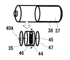
- FIG. 7 is an explanatory diagram of a support mechanism that supports a power receiving coil having high directivity.
- the ferrite coil 44 shown in FIG. 7 is provided with a mechanism (power receiving coil support mechanism 45) that rotates while being supported by the rotating shaft.
- the ferrite coil 44 is arranged between the power receiving circuit board 35 and the fixed plate 47 by a rotating shaft.
- a weight 46 is attached to the portion to which the ferrite coil 44 is fixed so that the ferrite coil faces the power feeder.
- the ferrite coil 44 is designed to always face downward according to the gravity of the earth by the functions of the power receiving coil support mechanism 45 and the weight 46.
- the ferrite coil 44 is aligned with the direction in which the magnetic flux from the power supply coil is received. Note that connection from the ferrite coil 44 to the power receiving circuit board 35 by an electric wire must be considered.
- the rotating shaft of the power receiving coil support mechanism 45 may be rotatable up to 360 degrees at the maximum.
- FIG. 8 shows an example of connection of the external secondary battery secondary battery 50.
- the button battery type power receiver 30 is shown here, a similar function can be added to a dry battery type power receiver. If a super capacitor is used instead of the internal secondary battery built in the power receiver 30, the battery becomes a temporary battery in a short time. Also, quick charging is possible. Then, the external secondary battery connecting terminals 51A and 51B depicted in FIG. 8 are provided so that the external secondary battery 50 can be attached. Then, even a small-capacity type such as a button battery can be used as a large-capacity battery. At this time, the built-in super capacitor acts as a power stabilization. In the case of the configuration of FIG. 8, since the button battery holder of the device equipped with the battery can be used as it is, a high-capacity secondary battery capable of wireless power feeding can be used as long as there is space for an external secondary battery without mechanical change of the device. Batteries can be constructed.
- FIG. 9 shows an embodiment of a power feeder for a dry battery type power receiver.
- the power feeder shown in FIG. 9(1) can wirelessly charge a plurality of dry battery type power receivers at the same time.
- a mechanism having four grooves 22 is presented so that a maximum of four power receivers can be wirelessly charged at the same time. Since the dry battery has a columnar shape, it rolls, so the mechanism having a slight groove 22 is used.
- the groove 22 may be a curved groove having a size larger than that of the dry battery as shown in FIG. 9 or may be a groove smaller than the dry battery.
- the dry battery type power receiver is effectively used in such a manner that it can be wirelessly fed while being attached to a device having a built-in power receiver. Therefore, the groove of the power feeder in FIG. 9 is characterized in that it does not interfere with the placement of the device with the built-in power receiver. This is shown in the diagram of FIG. 9(2).
- the power feeder has at least an indicator that indicates charging, a power switch, a power cable, and an AC power source. It is also possible to incorporate a power source in this power feeder. Further, a means for supplying power from a USB of a computer or the like is also possible.
- FIG. 10 shows an embodiment of a power supply for a coin battery type power receiver.
- This power feeder can simultaneously wirelessly charge a plurality of dry battery type power receivers.
- FIG. 10 shows a mechanism capable of wirelessly charging two power receivers at the same time, one of which is a device with a built-in power receiver.
- a rubber is attached to indicate a range 21 in which power can be supplied (effective area for power supply) and to prevent slippage.
- the power feeder has at least an indicator that indicates charging, a power switch, a power cable, and an AC power source.
- a power supply may be built in or a means for supplying power from a USB or the like may be used.
- FIG. 12 is a diagram showing a basic circuit configuration diagram of the wireless power supply system according to the present invention.
- the wireless power feeding system according to the present invention is configured by a combination of a power feeder 110 and a power receiver 130. Electrical energy is supplied from the power feeder 110 to the power receiver 130.
- the power receiver 130 includes a power receiving coil 131, a capacitor 133, a diode 132, a rectifier circuit 134, and an internal secondary battery 137.
- the internal secondary battery 137 is mounted inside the power receiver 130.
- the power receiving coil 131 provided in the power receiving device 130 allows the power feeding coil 111 of the power feeding device 110 to be greatly different in size, material, and electrical specifications.
- the shape of the power receiving coil 131 is characteristic, and the power receiving coil 131 has a coil shape capable of receiving power from any direction.
- the power receiver 130 is housed in an existing dry battery or button battery type case, and substitutes for the battery by producing an electric output equivalent to that of the battery.
- the power supply device 110 adjusts the power supply coil 111, a resonance capacitor 113 that forms a resonance circuit together with the power supply coil 111, a switch circuit 114 for turning on and off power to the power supply coil 111, and a frequency supplied to the power supply coil 111. It includes a frequency adjusting circuit 115 (for example, a circuit including a PLL circuit), a resonance state sensor 116 that detects a resonance state, and a power supply 118.
- the characteristics of the power feeder 110 side will be given. First, the power feeding coil 111 and the resonance capacitor 113 form a parallel resonance circuit. Second, there is one switch in FIG. 17 (the prior art depicted in FIG. 11 has two switches).
- control circuit 117 controls the frequency adjustment circuit 115 and the switch circuit 114 to control the frequency and the power supply time.
- the resonance state sensor 116 that detects the resonance state (mainly the frequency shift) is provided, and the control circuit 117 stops the power supply in addition to the control based on the detection result of the resonance state sensor 116. Take control.
- FIG. 12 shows a basic circuit diagram (close to the block diagram).
- the basic circuit is provided with a feeding coil 111, which generates electromagnetic waves and causes electromagnetic induction.
- At least the electric circuit of the power feeder 110 is provided with a resonance capacitor 113 and a power source 118, and creates a resonance relationship at a constant frequency with the power receiving coil 131 of the power receiver 130.
- the frequency at this time is called a resonance frequency, and generally, a frequency from 100 kHz to 500 kHz is used.
- the resonance frequency used in the present invention is not particularly limited.
- ⁇ Some deviation in the resonance frequency occurs due to the positional relationship and state of the power receiver 130. For example, the situation changes depending on the position and inclination of the power receiving coil 131 of the power receiver 130. Therefore, if the power receiving coil 131 enters the range of the electromagnetic waves transmitted from the power feeding coil 111 (in the magnetic flux lines shown in FIG. 12), energy can be supplied. The inclusion of the power receiving coil 131 in the magnetic flux lines affects the power feeder side in the form of deviation of the resonance frequency. If the resonance frequency shifts, the efficiency of energy supply decreases.
- the shifted frequency or phase is detected by the resonance state sensor 116 (for example, a circuit including a phase detection circuit), and the frequency of the power feeding coil 111 is adjusted using the frequency adjustment circuit 115 according to the frequency or phase.
- the frequency adjusting circuit 115 can be configured by, for example, a circuit having a built-in PLL (Phase Locked Loop) circuit.
- a control circuit 117 that controls by a program using a microcontroller (an integrated circuit including a processor, a memory, a peripheral circuit) or a programmable logic device (an integrated circuit that can define and change an internal logic circuit). ..
- the control circuit 117 is connected to the resonance state sensor 116 (phase detection circuit).
- the resonance state sensor 116 detects a frequency shift or a phase shift and transmits the signal to the control circuit 117. Thereby, when an object other than the predetermined power receiver 130 approaches, the resonance state sensor 116 detects an abnormal frequency or phase, transmits the signal to the control circuit 117, and the control circuit 117 stops power supply. It becomes possible.
- the present invention is characterized in that the circuit of the power feeder 110 shown in FIG. 12 employs a parallel resonant circuit. Further, in the conventional example shown in FIG. 11, two switches, that is, a switch 1 and a switch 2 are used to periodically stop the resonance from the feeding coil and detect it to detect a frequency shift. On the other hand, the circuit of FIG. 12 uses a method of detecting the resonance state without stopping the power supply to the power supply coil 111.
- the wireless power supply system of the present invention is composed of the basic circuit shown in FIG.
- the position of the resonance capacitor 113 of the power feeder 110 is connected in parallel with the power feeding coil 111.
- the circuit in which the resonance capacitor 113 is arranged is generally called a parallel resonance circuit.
- a series resonance circuit is formed, and the position of this resonance capacitor is arranged in series with the coil.
- this parallel resonance circuit when SW1 is turned on to enter a stable resonance state and then SW1 is turned off, resonance with the power receiver 130 occurs while the energy stored in the power receiving coil 131 and the capacitor 133 is released.
- the feature is that the power supply 110 continues the state.
- the frequency adjustment circuit (PLL circuit) 115 and the control circuit 117 realize power supply at an appropriate frequency based on the transition of the resonance state detected by the resonance state sensor 116 connected in parallel with the power feeding coil 111.
- the resonance state sensor 116 is a sensor that detects a resonance state, and detects transition of voltage/current, phase detection of resonance frequency, and the like.
- the power receiving coil 131 in FIG. 12 is a characteristic ferrite coil in which one ferrite has two kinds of winding coils in two directions. Drawing a circuit diagram, two coils are connected in series. Here, the diode 132 is installed so that the reverse current does not flow.
- FIG. 13 is a schematic diagram of signal waveforms of the basic circuit of the power feeder 110 of FIG.
- FIG. 13A shows the waveform of the switch circuit 14 in FIG. 12, which is switched on when the waveform is high. That is, when the switch is turned on, the power supply 118 is supplied, so that the driving state, that is, the driving time is reached. The time when the switch is turned off and is not driven is the resonance state, that is, the resonance time.
- the power feeding coil 111 and the resonance capacitor 113 constitute a parallel resonance circuit
- the power feeding device 110 and the power receiving device 130 may be in a resonance state regardless of whether they are in a driving state or a resonance state. If so, continue to supply energy.
- FIG. 13B shows a drive signal.
- the power supply 118 is turned on when the switch circuit 114 is turned on.
- FIG. 13C shows a sampling signal detected by the resonance state sensor 116 of FIG. 12, and the signal is turned on a plurality of times during the sampling time to perform detection (sampling).
- FIG. 13D is the received signal input to the resonance state sensor 116 of FIG. This signal indicates the state of the power feeding coil 111 in the resonance state. Although this signal waveform is simply shown, it is a signal having frequency characteristics, and the frequency component can be measured. Mainly, the voltage is converted into a digital value by an AD conversion circuit or the like, and the information is sent to the control circuit 117 in FIG.
- the control circuit 117 cooperates with the frequency adjustment circuit 115 to make a composite determination of these, and adjusts the frequency at the time of power supply. At times, the frequency is intentionally shifted back and forth, and the change in the state of FIG. 13D is also examined. In the case where the power receiver 130 is in resonance with the power receiver 130, the control circuit 117 also adjusts the driving time in consideration of how the voltage in FIG.
- the resonance state sensor 116 of FIG. 13(C) also involves the loss of energy as the power feeder 110. Therefore, it is possible to suppress the energy loss by sampling intermittently, for example, once a second, without performing each time.
- the specifications of the power supply 118, the power feeding coil 111, and the resonance frequency are determined according to the amount of energy to be sent and the area and height of the area to be fed with power.
- the resonance capacitor 113 is mainly determined according to the specifications of the reference resonance frequency.
- the circuit of the power receiver 30 includes a predetermined power receiving coil 131, and at least a diode 132, a capacitor 133, and a rectifying circuit 134.
- An internal secondary battery 137 is built in the power receiver 130.
- the internal secondary battery 137 is a rechargeable secondary battery.
- a super capacitor (electric double layer capacitor) may be used instead of the secondary battery.
- the specifications and volume of the power receiving coil 131 and the resonance frequency at this time are set according to the magnitude of energy to be received, but it is also possible to design so that the volume to be stored as the power receiver 130 has priority.
- the power receiving coil that can receive power from any direction according to the present invention is a special ferrite coil in which the winding of the ferrite coil is wound around one ferrite in two or three directions. As a result, an electromotive force due to electromagnetic induction is generated in the coil according to the winding direction in any magnetic flux direction.
- the power receiver 130 side is often provided with a frequency detection circuit and a communication means to the power feeder 110, which indicates the state of the power receiver 130. .. It transmits to the electric power feeder 110 by a communication means, and the electric power feeder 110 has the structure which adjusts a resonance frequency suitably. In that case, the power receiver 110 needs a predetermined IC circuit.
- the circuit of the power receiver 130 is configured by a mechanism that simplifies the circuit to the utmost limit. With this simplified structure, it is possible to discharge while charging, so you can charge the wireless power supply system with the charger installed inside the electronic device, and at the same time discharge the electronic device to generate power. Can be supplied.
- the power receiving coil that can receive power from any direction of the present invention is a special ferrite coil in which the winding of the ferrite coil is wound around one ferrite in two or three directions. As a result, an electromotive force due to electromagnetic induction is generated in the coil according to the winding direction in any magnetic flux direction.
- FIG. 15 is a configuration diagram of a power receiver having the same shape as a dry battery which is another embodiment of the power receiver of the present invention.
- the power receiver having the same shape as the dry battery is housed in a dry battery type case having electrode terminals of the dry battery.
- a power receiving coil 131, an internal secondary battery 137, and a power receiving circuit board (a condenser, a rectifying circuit, etc.) are housed inside a dry battery type case.
- a shield plate 136 that serves as an electromagnetic shield is attached to the power receiving coil 131.
- the power receiving circuit 135 is placed in the gap between the power receiving coils 131 in order to be built in a small storage volume.
- the electrode terminals 140A and 140B are attached from the power receiving circuit board 135 to the electrode terminals 139A and 139B provided on the power receiver housing 138 having the same shape as the dry battery. Regarding the connection between the electrode terminal 139B and the electrode terminal 140B, the electrode of the internal secondary battery 137 may be used as it is instead of the wiring connection.
- FIG. 16 shows an example in which a dry battery type power receiver (a power receiver having a power receiver housing having the same shape as the dry battery) is provided with a power receiving coil capable of receiving power from any direction.
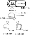
- the power receiving coil 131 is a ferrite coil that can receive power from any direction. In the case of a power receiving coil with high directivity, it was necessary to set the direction to match the direction of the magnetic flux from the power feeder, but if it is a ferrite coil power receiving coil that can receive power from any direction, that is Can be solved.
- the dry battery Since the dry battery has a cylindrical shape, there is a problem that the directivity is high when the dry battery has a general ferrite coil shape when rotated with respect to the cylindrical shape. However, according to the present invention, it is possible to receive power in the same way no matter how it rotates.
- two types of coil winding A and coil winding B are wound on one ferrite in the form that they intersect in the vertical direction.
- it is possible to use three types of windings for one ferrite because it is assumed to be a cylinder like a dry battery. In that case, it can be used as a spherical power receiving device instead of a cylinder, and can be rotated 360 degrees in any rotation direction.
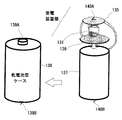
- FIG. 17 shows an embodiment of a power feeder for a dry battery type power receiver.
- the power feeder of FIG. 17(1) can wirelessly charge a plurality of dry battery type power receivers at the same time.
- FIG. 17 presents a mechanism having four grooves 122 so that a maximum of four power receivers can be wirelessly charged at the same time. Since the dry battery has a columnar shape, the dry battery rolls, so a mechanism having a slight groove 122 is used.
- the groove 122 may be a curved groove having a size larger than that of the dry battery as shown in FIG. 17, or may be a groove smaller than the dry battery.
- the effective use of the dry battery type power receiver is that it can be wirelessly fed while it is installed in a device with a built-in power receiver.
- a device with a built-in power receiving device As shown in the image of a device with a built-in power receiving device as shown in FIG. 14, there is a battery holder on the back surface of the device, and two dry battery type power receiving devices are contained therein. Even when the battery 122 is placed on the dry battery type power receiver 130, the groove 122 is a groove that does not interfere, so that the secondary battery of the power receiving device can be charged without care.
- the power feeder has at least an indicator that indicates charging, a power switch, a power cable, and an AC power source. It is also possible to incorporate a power source in this power feeder. Further, a means for supplying power from a USB of a computer or the like is also possible.
- the wireless power supply system of the present invention can provide a battery that replaces the battery in a device that uses a battery and replaces the battery when the battery cannot be used, by using the product of the present invention.
- a dry battery if the battery is exhausted, the battery will be replaced from the device and the battery will be discarded. Battery waste is a social problem.
- a rechargeable battery has to be taken out of the device and charged with a charger.
- a secondary battery having a built-in power receiving unit that receives power from wireless power supply can be used in the same manner as a general button battery or dry battery, so the device can be modified. Without making it, it can be a device that can be wirelessly charged.
- the side providing the product can replace it with a wirelessly rechargeable device without any special design change. Further, it is not necessary to provide a lid for replacing the battery on the housing of the electronic device. Therefore, the product design can be made more beautiful. Further, it can be used for manufacturing earth-friendly electronic devices without the need for battery replacement. Further, according to the present invention, in the case of a dry battery type power receiving device, wireless charging is possible in the same rotation direction as the dry battery with respect to the cylinder.
- Power receiver housing of the same shape as the dry battery 139 Electrode terminal (housing side) 139A (+ side of dry battery type case) Electrode terminal 139B (-side of dry battery type case) 140 Electrode terminal (inside) 140A (+ side) Electrode terminal (inside) 140B (- side) Electrode terminal (inside)
Landscapes
- Engineering & Computer Science (AREA)
- Power Engineering (AREA)
- Computer Networks & Wireless Communication (AREA)
- Signal Processing (AREA)
- Charge And Discharge Circuits For Batteries Or The Like (AREA)
- Secondary Cells (AREA)
Priority Applications (4)
| Application Number | Priority Date | Filing Date | Title |
|---|---|---|---|
| US17/432,765 US12212152B2 (en) | 2019-02-21 | 2020-02-17 | Wireless power feeding system, and power receiver having circular, spherical, or polyhedral shape |
| CN202080030396.8A CN113711466B (zh) | 2019-02-21 | 2020-02-17 | 具有圆形、球形或多面体形状的无线电力馈送系统和电力接收器 |
| JP2021501964A JP7261506B2 (ja) | 2019-02-21 | 2020-02-17 | ワイヤレス給電システムおよび円形・球形・多面形状を有する受電器 |
| KR1020207018513A KR102822700B1 (ko) | 2019-02-21 | 2020-02-17 | 무선급전시스템 및 원형 구형 다면형상을 갖는 수전기 |
Applications Claiming Priority (2)
| Application Number | Priority Date | Filing Date | Title |
|---|---|---|---|
| JP2019-029479 | 2019-02-21 | ||
| JP2019029479 | 2019-02-21 |
Publications (1)
| Publication Number | Publication Date |
|---|---|
| WO2020170996A1 true WO2020170996A1 (ja) | 2020-08-27 |
Family
ID=72144902
Family Applications (1)
| Application Number | Title | Priority Date | Filing Date |
|---|---|---|---|
| PCT/JP2020/005953 Ceased WO2020170996A1 (ja) | 2019-02-21 | 2020-02-17 | ワイヤレス給電システムおよび円形・球形・多面形状を有する受電器 |
Country Status (5)
| Country | Link |
|---|---|
| US (1) | US12212152B2 (https=) |
| JP (1) | JP7261506B2 (https=) |
| KR (1) | KR102822700B1 (https=) |
| CN (1) | CN113711466B (https=) |
| WO (1) | WO2020170996A1 (https=) |
Cited By (2)
| Publication number | Priority date | Publication date | Assignee | Title |
|---|---|---|---|---|
| WO2024177144A1 (ja) * | 2023-02-26 | 2024-08-29 | 作政 斉山 | 無線電力移送システムの受信装置および無線電力移送システム |
| WO2025248652A1 (ja) * | 2024-05-29 | 2025-12-04 | Ntt株式会社 | 電池モジュール |
Citations (4)
| Publication number | Priority date | Publication date | Assignee | Title |
|---|---|---|---|---|
| CN2852415Y (zh) * | 2005-07-27 | 2006-12-27 | 张定港 | 隔离式充电装置及电池充电装置 |
| JP2011045236A (ja) * | 2009-07-21 | 2011-03-03 | Sanyo Electric Co Ltd | 非接触式充電器 |
| WO2013021801A1 (ja) * | 2011-08-09 | 2013-02-14 | Fdk株式会社 | 非接触充電対応型二次電池、非接触充電器 |
| JP2015088376A (ja) * | 2013-10-31 | 2015-05-07 | 日立マクセル株式会社 | 電池ユニット及び充電システム |
Family Cites Families (40)
| Publication number | Priority date | Publication date | Assignee | Title |
|---|---|---|---|---|
| AU3046297A (en) * | 1997-06-16 | 1999-01-04 | Yehuda Binder | Battery substitute pack |
| GB0210886D0 (en) * | 2002-05-13 | 2002-06-19 | Zap Wireless Technologies Ltd | Improvements relating to contact-less power transfer |
| US7388350B1 (en) * | 2003-05-06 | 2008-06-17 | Cypress Semiconductor Corporation | Battery with electronic compartment |
| US8310201B1 (en) * | 2003-05-06 | 2012-11-13 | Cypress Semiconductor Corporation | Battery with electronic compartment |
| JP4540723B2 (ja) * | 2008-04-24 | 2010-09-08 | 三洋電機株式会社 | パック電池 |
| US8810194B2 (en) * | 2008-11-20 | 2014-08-19 | Qualcomm Incorporated | Retrofitting wireless power and near-field communication in electronic devices |
| US8159181B2 (en) * | 2009-02-05 | 2012-04-17 | Infineon Technologies Ag | Combining two or more DC to DC converters to limit external coils |
| JP5069726B2 (ja) | 2009-07-24 | 2012-11-07 | Tdk株式会社 | ワイヤレス給電装置およびワイヤレス電力伝送システム |
| US20110049997A1 (en) * | 2009-09-03 | 2011-03-03 | Tdk Corporation | Wireless power feeder and wireless power transmission system |
| JP5573190B2 (ja) | 2010-01-21 | 2014-08-20 | ソニー株式会社 | ワイヤレス給電システム |
| JP5640782B2 (ja) | 2010-03-19 | 2014-12-17 | Tdk株式会社 | ワイヤレス給電装置、ワイヤレス受電装置およびワイヤレス電力伝送システム |
| US8791601B2 (en) | 2010-04-02 | 2014-07-29 | Advantest Corporation | Wireless power receiving apparatus and wireless power supply system |
| JP2011223739A (ja) | 2010-04-09 | 2011-11-04 | Sony Corp | 給電装置、受電装置、およびワイヤレス給電システム |
| CN103329398B (zh) | 2011-01-26 | 2015-07-01 | 株式会社村田制作所 | 电力输送系统 |
| US8742627B2 (en) | 2011-03-01 | 2014-06-03 | Tdk Corporation | Wireless power feeder |
| JP2012221854A (ja) * | 2011-04-12 | 2012-11-12 | Sanyo Electric Co Ltd | 出力コネクタを備えるバッテリパック |
| JP2012253944A (ja) | 2011-06-03 | 2012-12-20 | Advantest Corp | ワイヤレス給電装置およびワイヤレス給電システム |
| US9641027B2 (en) * | 2011-09-21 | 2017-05-02 | Nec Corporation | Wireless power feeding system and wireless power feeding method |
| JP2013162611A (ja) | 2012-02-03 | 2013-08-19 | Seiko Instruments Inc | ワイヤレス給電装置 |
| CN106887883B (zh) | 2012-02-29 | 2019-08-23 | 松下知识产权经营株式会社 | 充电装置 |
| JP5794203B2 (ja) | 2012-05-22 | 2015-10-14 | トヨタ自動車株式会社 | 送電装置、受電装置、車両、および非接触給電システム |
| JP2014068507A (ja) | 2012-09-27 | 2014-04-17 | Tdk Corp | ワイヤレス給電システム |
| CN106961164A (zh) | 2012-10-11 | 2017-07-18 | 株式会社村田制作所 | 无线供电装置 |
| US9768643B2 (en) | 2012-11-02 | 2017-09-19 | Panasonic Intellectual Property Management Co., Ltd. | Wireless power transmission system capable of continuing power transmission while suppressing heatup of foreign objects |
| KR101427747B1 (ko) | 2012-11-28 | 2014-08-07 | (주)유비쿼터스통신 | 맥박 시계를 이용한 응급조치 시스템 |
| JP2014176122A (ja) | 2013-03-06 | 2014-09-22 | Osaka City Univ | 磁気共振型ワイヤレス給電システム |
| JP2015053751A (ja) | 2013-09-05 | 2015-03-19 | Tdk株式会社 | 非接触電力伝送装置 |
| JP2015159664A (ja) * | 2014-02-24 | 2015-09-03 | 日東電工株式会社 | 携帯機器用電源装置及びその充電装置 |
| EP3195444B1 (en) | 2014-09-16 | 2018-04-04 | Koninklijke Philips N.V. | Wireless inductive power transfer |
| CN104382547A (zh) * | 2014-11-18 | 2015-03-04 | 上海交通大学 | 用于胶囊内窥镜的穿戴式无线能量传输设备 |
| KR20160078186A (ko) * | 2014-12-24 | 2016-07-04 | 삼성전기주식회사 | 코일 구조체 및 그를 이용한 무선 전력 송신 장치 |
| US10559971B2 (en) * | 2015-04-10 | 2020-02-11 | Ossia Inc. | Wirelessly chargeable battery apparatus |
| JP6555517B2 (ja) | 2015-07-16 | 2019-08-07 | 清水建設株式会社 | ワイヤレス給電システム |
| CA3041583A1 (en) * | 2015-10-29 | 2017-05-04 | PogoTec, Inc. | Hearing aid adapted for wireless power reception |
| CN105361841B (zh) * | 2015-11-30 | 2018-10-16 | 青岛大学附属医院 | 用于胃肠道诊疗的无线胶囊内窥镜系统 |
| JP2017163647A (ja) | 2016-03-08 | 2017-09-14 | 達也 土井 | 電磁界共振ワイヤレス給電方法及び給電システム |
| WO2017174359A1 (de) * | 2016-04-04 | 2017-10-12 | Tecflower Ag | Drahtlos wiederaufladbarer energiespeicher |
| WO2018037758A1 (ja) | 2016-08-23 | 2018-03-01 | 株式会社村田製作所 | 受電装置および送電装置 |
| CN207946922U (zh) * | 2018-03-15 | 2018-10-09 | 杭州水豚科技有限公司 | 一种无线充电游泳智能预警救援器 |
| KR102898613B1 (ko) | 2019-12-20 | 2025-12-10 | 레존테크 인크. | 튜닝조정회로를 갖는 무선급전시스템 |
-
2020
- 2020-02-17 US US17/432,765 patent/US12212152B2/en active Active
- 2020-02-17 WO PCT/JP2020/005953 patent/WO2020170996A1/ja not_active Ceased
- 2020-02-17 CN CN202080030396.8A patent/CN113711466B/zh active Active
- 2020-02-17 JP JP2021501964A patent/JP7261506B2/ja active Active
- 2020-02-17 KR KR1020207018513A patent/KR102822700B1/ko active Active
Patent Citations (4)
| Publication number | Priority date | Publication date | Assignee | Title |
|---|---|---|---|---|
| CN2852415Y (zh) * | 2005-07-27 | 2006-12-27 | 张定港 | 隔离式充电装置及电池充电装置 |
| JP2011045236A (ja) * | 2009-07-21 | 2011-03-03 | Sanyo Electric Co Ltd | 非接触式充電器 |
| WO2013021801A1 (ja) * | 2011-08-09 | 2013-02-14 | Fdk株式会社 | 非接触充電対応型二次電池、非接触充電器 |
| JP2015088376A (ja) * | 2013-10-31 | 2015-05-07 | 日立マクセル株式会社 | 電池ユニット及び充電システム |
Cited By (2)
| Publication number | Priority date | Publication date | Assignee | Title |
|---|---|---|---|---|
| WO2024177144A1 (ja) * | 2023-02-26 | 2024-08-29 | 作政 斉山 | 無線電力移送システムの受信装置および無線電力移送システム |
| WO2025248652A1 (ja) * | 2024-05-29 | 2025-12-04 | Ntt株式会社 | 電池モジュール |
Also Published As
| Publication number | Publication date |
|---|---|
| US20230013502A1 (en) | 2023-01-19 |
| JP7261506B2 (ja) | 2023-04-20 |
| CN113711466B (zh) | 2025-04-29 |
| US12212152B2 (en) | 2025-01-28 |
| CN113711466A (zh) | 2021-11-26 |
| JPWO2020170996A1 (https=) | 2020-08-27 |
| KR20210124885A (ko) | 2021-10-15 |
| KR102822700B1 (ko) | 2025-06-19 |
Similar Documents
| Publication | Publication Date | Title |
|---|---|---|
| EP3093958B1 (en) | Foreign object detecting device, wireless power transmitting apparatus, and wireless power transfer system | |
| EP2693601B1 (en) | Power supply device, power supply system, and electronic device | |
| KR101140181B1 (ko) | 공명형 비접촉 전력 전송 장치 | |
| JP5177187B2 (ja) | 電力伝送システム | |
| US10069340B2 (en) | Wireless power receiver for adjusting magnitude of wireless power | |
| EP2745412B1 (en) | Wireless power receiver with multiple receiver coils | |
| KR101893104B1 (ko) | 스위치를 이용하여 무선 전력을 조정하는 무선 전력 수신기 | |
| US9461476B2 (en) | Power transmission device and wireless power transmission system including the same | |
| EP2278654B1 (en) | Contactless cell apparatus | |
| US9270124B2 (en) | Contactless power supply device | |
| EP3093957A1 (en) | Foreign object detecting device, wireless power transmitting apparatus, and wireless power transfer system | |
| US20140080409A1 (en) | Static tuning of wireless transmitters | |
| WO2014163874A2 (en) | Systems and methods for extending the power capability of a wireless charger | |
| CN105814772A (zh) | 混合式无线电力传输系统及其方法 | |
| JPWO2012090701A1 (ja) | ワイヤレス給電装置、ワイヤレス受電装置、ワイヤレス電力伝送システム | |
| JP2013017254A (ja) | 電力伝送システム | |
| EP2867976A1 (en) | Miniature low-power remote battery charging systems and methods | |
| US20250079903A1 (en) | Wireless power transmission device | |
| JP2011259534A (ja) | 電池内蔵機器と充電台 | |
| JP6981480B2 (ja) | 受電器、電力伝送システム、及び受電方法 | |
| CN115152125A (zh) | 具有调谐调整电路的无线功率馈送系统 | |
| WO2020170996A1 (ja) | ワイヤレス給電システムおよび円形・球形・多面形状を有する受電器 | |
| CN108604826A (zh) | 供电装置以及受电供电装置 | |
| KR20150039809A (ko) | 무선 전력 전송 장치 및 무선 전력 전송 장치의 전력 공급 방법 | |
| CN106208288A (zh) | 功率馈送器和功率馈送系统 |
Legal Events
| Date | Code | Title | Description |
|---|---|---|---|
| 121 | Ep: the epo has been informed by wipo that ep was designated in this application |
Ref document number: 20759215 Country of ref document: EP Kind code of ref document: A1 |
|
| ENP | Entry into the national phase |
Ref document number: 2021501964 Country of ref document: JP Kind code of ref document: A |
|
| NENP | Non-entry into the national phase |
Ref country code: DE |
|
| 122 | Ep: pct application non-entry in european phase |
Ref document number: 20759215 Country of ref document: EP Kind code of ref document: A1 |
|
| WWG | Wipo information: grant in national office |
Ref document number: 202080030396.8 Country of ref document: CN |